JP6367001B2 - Display device and liquid crystal display device - Google Patents
Display device and liquid crystal display device Download PDFInfo
- Publication number
- JP6367001B2 JP6367001B2 JP2014108205A JP2014108205A JP6367001B2 JP 6367001 B2 JP6367001 B2 JP 6367001B2 JP 2014108205 A JP2014108205 A JP 2014108205A JP 2014108205 A JP2014108205 A JP 2014108205A JP 6367001 B2 JP6367001 B2 JP 6367001B2
- Authority
- JP
- Japan
- Prior art keywords
- layer
- light
- wavelength conversion
- conversion layer
- backlight
- Prior art date
- Legal status (The legal status is an assumption and is not a legal conclusion. Google has not performed a legal analysis and makes no representation as to the accuracy of the status listed.)
- Active
Links
Images


Classifications
-
- G—PHYSICS
- G02—OPTICS
- G02F—OPTICAL DEVICES OR ARRANGEMENTS FOR THE CONTROL OF LIGHT BY MODIFICATION OF THE OPTICAL PROPERTIES OF THE MEDIA OF THE ELEMENTS INVOLVED THEREIN; NON-LINEAR OPTICS; FREQUENCY-CHANGING OF LIGHT; OPTICAL LOGIC ELEMENTS; OPTICAL ANALOGUE/DIGITAL CONVERTERS
- G02F1/00—Devices or arrangements for the control of the intensity, colour, phase, polarisation or direction of light arriving from an independent light source, e.g. switching, gating or modulating; Non-linear optics
- G02F1/01—Devices or arrangements for the control of the intensity, colour, phase, polarisation or direction of light arriving from an independent light source, e.g. switching, gating or modulating; Non-linear optics for the control of the intensity, phase, polarisation or colour
- G02F1/13—Devices or arrangements for the control of the intensity, colour, phase, polarisation or direction of light arriving from an independent light source, e.g. switching, gating or modulating; Non-linear optics for the control of the intensity, phase, polarisation or colour based on liquid crystals, e.g. single liquid crystal display cells
- G02F1/133—Constructional arrangements; Operation of liquid crystal cells; Circuit arrangements
- G02F1/1333—Constructional arrangements; Manufacturing methods
- G02F1/1343—Electrodes
- G02F1/134309—Electrodes characterised by their geometrical arrangement
- G02F1/134363—Electrodes characterised by their geometrical arrangement for applying an electric field parallel to the substrate, i.e. in-plane switching [IPS]
-
- F—MECHANICAL ENGINEERING; LIGHTING; HEATING; WEAPONS; BLASTING
- F21—LIGHTING
- F21V—FUNCTIONAL FEATURES OR DETAILS OF LIGHTING DEVICES OR SYSTEMS THEREOF; STRUCTURAL COMBINATIONS OF LIGHTING DEVICES WITH OTHER ARTICLES, NOT OTHERWISE PROVIDED FOR
- F21V9/00—Elements for modifying spectral properties, polarisation or intensity of the light emitted, e.g. filters
- F21V9/30—Elements containing photoluminescent material distinct from or spaced from the light source
-
- G—PHYSICS
- G02—OPTICS
- G02F—OPTICAL DEVICES OR ARRANGEMENTS FOR THE CONTROL OF LIGHT BY MODIFICATION OF THE OPTICAL PROPERTIES OF THE MEDIA OF THE ELEMENTS INVOLVED THEREIN; NON-LINEAR OPTICS; FREQUENCY-CHANGING OF LIGHT; OPTICAL LOGIC ELEMENTS; OPTICAL ANALOGUE/DIGITAL CONVERTERS
- G02F1/00—Devices or arrangements for the control of the intensity, colour, phase, polarisation or direction of light arriving from an independent light source, e.g. switching, gating or modulating; Non-linear optics
- G02F1/01—Devices or arrangements for the control of the intensity, colour, phase, polarisation or direction of light arriving from an independent light source, e.g. switching, gating or modulating; Non-linear optics for the control of the intensity, phase, polarisation or colour
- G02F1/13—Devices or arrangements for the control of the intensity, colour, phase, polarisation or direction of light arriving from an independent light source, e.g. switching, gating or modulating; Non-linear optics for the control of the intensity, phase, polarisation or colour based on liquid crystals, e.g. single liquid crystal display cells
- G02F1/133—Constructional arrangements; Operation of liquid crystal cells; Circuit arrangements
- G02F1/1333—Constructional arrangements; Manufacturing methods
- G02F1/1335—Structural association of cells with optical devices, e.g. polarisers or reflectors
- G02F1/1336—Illuminating devices
- G02F1/133602—Direct backlight
- G02F1/133605—Direct backlight including specially adapted reflectors
-
- G—PHYSICS
- G02—OPTICS
- G02F—OPTICAL DEVICES OR ARRANGEMENTS FOR THE CONTROL OF LIGHT BY MODIFICATION OF THE OPTICAL PROPERTIES OF THE MEDIA OF THE ELEMENTS INVOLVED THEREIN; NON-LINEAR OPTICS; FREQUENCY-CHANGING OF LIGHT; OPTICAL LOGIC ELEMENTS; OPTICAL ANALOGUE/DIGITAL CONVERTERS
- G02F1/00—Devices or arrangements for the control of the intensity, colour, phase, polarisation or direction of light arriving from an independent light source, e.g. switching, gating or modulating; Non-linear optics
- G02F1/01—Devices or arrangements for the control of the intensity, colour, phase, polarisation or direction of light arriving from an independent light source, e.g. switching, gating or modulating; Non-linear optics for the control of the intensity, phase, polarisation or colour
- G02F1/13—Devices or arrangements for the control of the intensity, colour, phase, polarisation or direction of light arriving from an independent light source, e.g. switching, gating or modulating; Non-linear optics for the control of the intensity, phase, polarisation or colour based on liquid crystals, e.g. single liquid crystal display cells
- G02F1/133—Constructional arrangements; Operation of liquid crystal cells; Circuit arrangements
- G02F1/1333—Constructional arrangements; Manufacturing methods
- G02F1/1335—Structural association of cells with optical devices, e.g. polarisers or reflectors
- G02F1/1336—Illuminating devices
- G02F1/133602—Direct backlight
- G02F1/133606—Direct backlight including a specially adapted diffusing, scattering or light controlling members
-
- G—PHYSICS
- G02—OPTICS
- G02F—OPTICAL DEVICES OR ARRANGEMENTS FOR THE CONTROL OF LIGHT BY MODIFICATION OF THE OPTICAL PROPERTIES OF THE MEDIA OF THE ELEMENTS INVOLVED THEREIN; NON-LINEAR OPTICS; FREQUENCY-CHANGING OF LIGHT; OPTICAL LOGIC ELEMENTS; OPTICAL ANALOGUE/DIGITAL CONVERTERS
- G02F1/00—Devices or arrangements for the control of the intensity, colour, phase, polarisation or direction of light arriving from an independent light source, e.g. switching, gating or modulating; Non-linear optics
- G02F1/01—Devices or arrangements for the control of the intensity, colour, phase, polarisation or direction of light arriving from an independent light source, e.g. switching, gating or modulating; Non-linear optics for the control of the intensity, phase, polarisation or colour
- G02F1/13—Devices or arrangements for the control of the intensity, colour, phase, polarisation or direction of light arriving from an independent light source, e.g. switching, gating or modulating; Non-linear optics for the control of the intensity, phase, polarisation or colour based on liquid crystals, e.g. single liquid crystal display cells
- G02F1/133—Constructional arrangements; Operation of liquid crystal cells; Circuit arrangements
- G02F1/136—Liquid crystal cells structurally associated with a semi-conducting layer or substrate, e.g. cells forming part of an integrated circuit
- G02F1/1362—Active matrix addressed cells
- G02F1/136286—Wiring, e.g. gate line, drain line
-
- G—PHYSICS
- G02—OPTICS
- G02F—OPTICAL DEVICES OR ARRANGEMENTS FOR THE CONTROL OF LIGHT BY MODIFICATION OF THE OPTICAL PROPERTIES OF THE MEDIA OF THE ELEMENTS INVOLVED THEREIN; NON-LINEAR OPTICS; FREQUENCY-CHANGING OF LIGHT; OPTICAL LOGIC ELEMENTS; OPTICAL ANALOGUE/DIGITAL CONVERTERS
- G02F1/00—Devices or arrangements for the control of the intensity, colour, phase, polarisation or direction of light arriving from an independent light source, e.g. switching, gating or modulating; Non-linear optics
- G02F1/01—Devices or arrangements for the control of the intensity, colour, phase, polarisation or direction of light arriving from an independent light source, e.g. switching, gating or modulating; Non-linear optics for the control of the intensity, phase, polarisation or colour
- G02F1/13—Devices or arrangements for the control of the intensity, colour, phase, polarisation or direction of light arriving from an independent light source, e.g. switching, gating or modulating; Non-linear optics for the control of the intensity, phase, polarisation or colour based on liquid crystals, e.g. single liquid crystal display cells
- G02F1/133—Constructional arrangements; Operation of liquid crystal cells; Circuit arrangements
- G02F1/136—Liquid crystal cells structurally associated with a semi-conducting layer or substrate, e.g. cells forming part of an integrated circuit
- G02F1/1362—Active matrix addressed cells
- G02F1/1368—Active matrix addressed cells in which the switching element is a three-electrode device
-
- G—PHYSICS
- G02—OPTICS
- G02F—OPTICAL DEVICES OR ARRANGEMENTS FOR THE CONTROL OF LIGHT BY MODIFICATION OF THE OPTICAL PROPERTIES OF THE MEDIA OF THE ELEMENTS INVOLVED THEREIN; NON-LINEAR OPTICS; FREQUENCY-CHANGING OF LIGHT; OPTICAL LOGIC ELEMENTS; OPTICAL ANALOGUE/DIGITAL CONVERTERS
- G02F1/00—Devices or arrangements for the control of the intensity, colour, phase, polarisation or direction of light arriving from an independent light source, e.g. switching, gating or modulating; Non-linear optics
- G02F1/01—Devices or arrangements for the control of the intensity, colour, phase, polarisation or direction of light arriving from an independent light source, e.g. switching, gating or modulating; Non-linear optics for the control of the intensity, phase, polarisation or colour
- G02F1/13—Devices or arrangements for the control of the intensity, colour, phase, polarisation or direction of light arriving from an independent light source, e.g. switching, gating or modulating; Non-linear optics for the control of the intensity, phase, polarisation or colour based on liquid crystals, e.g. single liquid crystal display cells
- G02F1/133—Constructional arrangements; Operation of liquid crystal cells; Circuit arrangements
- G02F1/1333—Constructional arrangements; Manufacturing methods
- G02F1/1335—Structural association of cells with optical devices, e.g. polarisers or reflectors
- G02F1/1336—Illuminating devices
- G02F1/133614—Illuminating devices using photoluminescence, e.g. phosphors illuminated by UV or blue light
Description
本発明は表示装置に係り、特に蛍光体を用いたバックライトを有する液晶表示装置に関する。 The present invention relates to a display device, and more particularly to a liquid crystal display device having a backlight using a phosphor.
液晶表示装置に使用される液晶表示パネルは、画素電極および薄膜トランジスタ(TFT)等を有する画素がマトリクス状に形成されたTFT基板と、TFT基板に対向して、対向基板が配置され、TFT基板と対向基板の間に液晶が挟持されている。そして液晶分子による光の透過率を画素毎に制御することによって画像を形成している。 A liquid crystal display panel used in a liquid crystal display device includes a TFT substrate in which pixels having pixel electrodes, thin film transistors (TFTs), and the like are formed in a matrix, and a counter substrate disposed opposite the TFT substrate. Liquid crystal is sandwiched between the counter substrates. An image is formed by controlling the light transmittance of the liquid crystal molecules for each pixel.
現在市販されている液晶表示装置にはフィールドシーケンシャル方式も一部含まれるが、大多数は白色光源からの白色光をカラーフィルタで吸収してカラー表示を行うカラーフィルタ方式である。色再現範囲の拡大と共にカラーフィルタの透過率が低減する傾向にあり、カラーフィルタはカラーフィルタ方式の液晶表示装置におけるエンルギー変換効率低下の主要因である。 Currently marketed liquid crystal display devices include a part of the field sequential method, but the majority are color filter methods that perform color display by absorbing white light from a white light source with a color filter. The transmittance of the color filter tends to decrease as the color reproduction range expands, and the color filter is a main factor in reducing the energy conversion efficiency in the color filter type liquid crystal display device.
カラーフィルタ方式以外のカラー表示方法として、前述のフィールドシーケンシャル方式の他にも蛍光体による波長変換を利用した方式がある。すなわち、光源に青色光源もしくは近紫外光源を用い、波長変換層で光源光を吸収し、蛍光を発光して光源光をより長波長の光に変換する。波長変換層には蛍光体を用いることから、蛍光体による波長変換を用いた表示装置をこの明細書では蛍光体表示装置と呼ぶこともある。 As a color display method other than the color filter method, there is a method using wavelength conversion by a phosphor other than the above-described field sequential method. That is, a blue light source or a near ultraviolet light source is used as the light source, the light source light is absorbed by the wavelength conversion layer, and fluorescence is emitted to convert the light source light into light having a longer wavelength. Since a phosphor is used for the wavelength conversion layer, a display device using wavelength conversion by the phosphor may be referred to as a phosphor display device in this specification.
このような表示装置を記載したものとして、特許文献1が挙げられる。特許文献1には、画素毎に蛍光体を含む単色層が形成され、蛍光体を含む単色層と蛍光体を含む単色層の間に光吸収層が形成され、蛍光体を含む単色層と光吸収層の間に反射膜が形成されている構成が記載されている。
蛍光体を用いてカラ表示を行う表示装置において、蛍光体は高い内部量子効率持つことが特長であるが、その活用には外部量子効率の向上が課題である。即ち蛍光は等方的に伝播するので、何も工夫しなければ使用者の観察する前方に出射する割合は極めて低い。層内や後方に向かう蛍光の方向を前方に変えて外部量子効率を向上するための構造は光取出し構造と呼ばれるが、光取出し構造によっては波長変換層の開口率が低下することがある。また、波長変換層を励起するバックライト光源に高いコリメート性が求められることがあるが、コリメート性の高いバックライト光源は効率が低いので好ましくない。 In a display device that performs color display using a phosphor, the phosphor is characterized by a high internal quantum efficiency. However, the improvement of the external quantum efficiency is a problem for its utilization. That is, since the fluorescence propagates isotropically, the ratio of the emission to the front observed by the user is extremely low unless anything is devised. A structure for improving the external quantum efficiency by changing the direction of fluorescence in the layer or toward the rear to the front is called a light extraction structure, but the aperture ratio of the wavelength conversion layer may decrease depending on the light extraction structure. Further, a high collimating property may be required for the backlight source that excites the wavelength conversion layer, but a backlight source having a high collimating property is not preferable because of its low efficiency.
コリメートバックライトを使わずに蛍光体表示装置の外部量子効率を向上するには、光取出し構造に工夫が必要であり、更には蛍光体表示装置全体の構成を最適化する必要がある。本発明の課題はこの様な蛍光体表示装置における外部量子効率を向上する構造を実現することである。 In order to improve the external quantum efficiency of the phosphor display device without using a collimated backlight, it is necessary to devise a light extraction structure, and further, it is necessary to optimize the configuration of the entire phosphor display device. An object of the present invention is to realize a structure that improves the external quantum efficiency in such a phosphor display device.
本発明は以上に述べた課題を解決するものであり、主な具体的な手段は次のとおりである。 The present invention solves the problems described above, and the main specific means are as follows.
(1)表示面を有する表示パネルとバックライトを有する表示装置であって、
前記表示パネルは、前記表示面と平行な面において、画素毎に波長変換層を有し、前記波長変換層と波長変換層の間に光散乱層を有し、前記波長変換層は蛍光体を有し、前記光散乱層は微粒子を有し、前記波長変換層の前記バックライト側は反射層を有し、前記光散乱層の前記表示面側は反射層を有することを特徴とする表示装置。
(1) A display device having a display panel having a display surface and a backlight,
The display panel has a wavelength conversion layer for each pixel in a plane parallel to the display surface, and has a light scattering layer between the wavelength conversion layer and the wavelength conversion layer, and the wavelength conversion layer includes a phosphor. And the light scattering layer has fine particles, the backlight side of the wavelength conversion layer has a reflective layer, and the display surface side of the light scattering layer has a reflective layer. .
(2)前記波長変換層の断面は、前記表示面側の幅が前記バックライト側の幅よりも大きい、台形であることを特徴とする(1)に記載の表示装置。 (2) The display device according to (1), wherein a cross section of the wavelength conversion layer is a trapezoid in which a width on the display surface side is larger than a width on the backlight side.
(3)前記光散乱層は、前記表示面側で光散乱が大きく、前記バックライト側で光散乱が小さいことを特徴とする(1)に記載の表示装置。 (3) The display device according to (1), wherein the light scattering layer has a large light scattering on the display surface side and a small light scattering on the backlight side.
(4)前記光散乱層における前記微粒子の濃度は、前記表示面側で大きく、前記バックライト側で小さいことを特徴とする(3)に記載の表示装置。 (4) The display device according to (3), wherein the concentration of the fine particles in the light scattering layer is large on the display surface side and small on the backlight side.
(5)前記光散乱層には、レジストに第1の微粒子を分散させた第1の光散乱層が前記表示面側に形成され、前記レジストに第2の微粒子を分散させた第2の光散乱層が前記バックライト側に形成されており、前記レジストの屈折率と前記第1の微粒子の屈折率の差は、前記レジストの屈折率と前記第2の微粒子の屈折率の差よりも大きいことを特徴とする(3)に記載の表示装置。 (5) In the light scattering layer, a first light scattering layer in which first fine particles are dispersed in a resist is formed on the display surface side, and second light in which second fine particles are dispersed in the resist. A scattering layer is formed on the backlight side, and the difference between the refractive index of the resist and the refractive index of the first fine particles is larger than the difference between the refractive index of the resist and the refractive indexes of the second fine particles. The display device according to (3), characterized in that:
(6)前記光散乱層の前記表示面側の前記反射層は、画素を区画するように、格子状に形成されていることを特徴とする(1)に記載の表示装置。 (6) The display device according to (1), wherein the reflective layer on the display surface side of the light scattering layer is formed in a lattice shape so as to partition pixels.
(7)表示面を有する表示パネルとバックライトを有する表示装置であって、前記表示パネルは、前記表示面と平行な面において、赤色を発光する波長変換層と、緑色を発光する波長変換層と、光透過層を有し、前記赤色を発光する波長変換層と、前記緑色を発光する波長変換層と、前記光透過層の間には光散乱層が形成され、前記赤色を発光する波長変換層と、前記緑色を発光する波長変換層と、前記光透過層の前記バックライト側は反射層を有し、前記光散乱層は前記表示面側に反射層を有し、前記バックライトの光源は青色発光LEDであることを特徴とする表示装置。 (7) A display device having a display surface and a backlight, the display panel having a wavelength conversion layer that emits red light and a wavelength conversion layer that emits green light on a surface parallel to the display surface. And a wavelength conversion layer that emits red light, a wavelength conversion layer that emits green light, and a light scattering layer that is formed between the light transmission layers and emits red light. A conversion layer; a wavelength conversion layer emitting green light; and the backlight side of the light transmission layer has a reflection layer, the light scattering layer has a reflection layer on the display surface side, and A display device, wherein the light source is a blue light emitting LED.
(8)表示面を有する表示パネルとバックライトを有する表示装置であって、前記表示パネルは、前記表示面と平行な面において、赤色を発光する波長変換層と、緑色を発光する波長変換層と、青色を発光する波長変換層を有し、前記赤色を発光する波長変換層と、前記緑色を発光する波長変換層と、前記青色を発光する波長変換層の間には光散乱層が形成され、前記赤色を発光する波長変換層と、前記緑色を発光する波長変換層と、前記青色を発光する波長変換層の前記バックライト側は反射層を有し、前記光散乱層は前記表示面側に反射層を有し、前記バックライトの光源は紫外線発光LEDであることを特徴とする表示装置。 (8) A display device having a display surface and a backlight, wherein the display panel has a wavelength conversion layer that emits red light and a wavelength conversion layer that emits green light on a surface parallel to the display surface. And a wavelength conversion layer that emits blue light, and a light scattering layer is formed between the wavelength conversion layer that emits red light, the wavelength conversion layer that emits green light, and the wavelength conversion layer that emits blue light The wavelength conversion layer emitting red light, the wavelength conversion layer emitting green light, and the backlight side of the wavelength conversion layer emitting blue light has a reflective layer, and the light scattering layer is the display surface A display device comprising a reflective layer on the side, and the light source of the backlight is an ultraviolet light emitting LED.
(9)第1の基板と第2の基板の間に液晶層が挟持された液晶表示パネルとバックライトを有する液晶表示装置であって、前記第1の基板には走査配線と信号配線に囲まれた領域に画素が形成され、前記画素にはTFTと接続した画素電極が形成され、前記第2の基板には前記画素に対応して波長変換層が形成され、前記波長変換層と前記波長変換層の間には光散乱層が形成され、前記波長変換層は蛍光体を有し、前記波長変換層の前記バックライト側には反射層が形成され、前記光散乱層の前記液晶層側には反射層が形成されていることを特徴とする液晶表示装置。 (9) A liquid crystal display device having a liquid crystal display panel and a backlight in which a liquid crystal layer is sandwiched between a first substrate and a second substrate, wherein the first substrate is surrounded by scanning lines and signal lines. A pixel is formed in the region, a pixel electrode connected to the TFT is formed on the pixel, a wavelength conversion layer is formed on the second substrate corresponding to the pixel, the wavelength conversion layer and the wavelength A light scattering layer is formed between the conversion layers, the wavelength conversion layer has a phosphor, a reflection layer is formed on the backlight side of the wavelength conversion layer, and the liquid crystal layer side of the light scattering layer A liquid crystal display device, wherein a reflective layer is formed on the liquid crystal display device.
(10)第1の基板と第2の基板の間に液晶層が挟持された液晶表示パネルとバックライトを有する液晶表示装置であって、前記第1の基板には走査配線と信号配線に囲まれた領域毎に赤画素、緑画素、青画素が形成され、前記赤画素、前記緑画素、前記青画素にはTFTと接続した画素電極が形成され、前記第2の基板には前記赤画素、前記緑画素、前記青画素に対応して赤色を発光する波長変換層、緑色を発光する波長変換層、光透過層が形成され、前記赤色を発光する波長変換層、前記緑色を発光する波長変換層、前記光透過層の前記バックライト側には光反射層が形成され、前記赤色を発光する波長変換層、前記緑色を発光する波長変換層、前記光透過層の間には光散乱層が形成され、前記光散乱層の前記液晶層側には反射層が形成され、前記バックライトの光源は青色を発光するLEDであることを特徴とする液晶表示装置。 (10) A liquid crystal display device having a liquid crystal display panel having a liquid crystal layer sandwiched between a first substrate and a second substrate and a backlight, wherein the first substrate is surrounded by scanning lines and signal lines. A red pixel, a green pixel, and a blue pixel are formed for each region, a pixel electrode connected to a TFT is formed on the red pixel, the green pixel, and the blue pixel, and the red pixel is formed on the second substrate. , A wavelength conversion layer that emits red corresponding to the green pixel, a wavelength conversion layer that emits green, a wavelength transmission layer that transmits light, and a wavelength conversion layer that emits red, and a wavelength that emits green A light reflection layer is formed on the backlight side of the conversion layer and the light transmission layer, the wavelength conversion layer emitting red light, the wavelength conversion layer emitting green light, and a light scattering layer between the light transmission layers And a reflective layer is formed on the liquid crystal layer side of the light scattering layer. Is the light source of the backlight liquid crystal display device, characterized in that the LED that emits blue.
(11)前記赤色を発光する波長変換層の前記液晶層側には赤カラーフィルタが配置し、前記緑色を発光する波長変換層には黄色カラーフィルタが配置していることを特徴とする(10)に記載の液晶表示装置。 (11) A red color filter is disposed on the liquid crystal layer side of the wavelength conversion layer emitting red light, and a yellow color filter is disposed on the wavelength conversion layer emitting green light (10 ) Liquid crystal display device.
(12)第1の基板と第2の基板の間に液晶層が挟持された液晶表示パネルとバックライトを有する液晶表示装置であって、前記第1の基板には走査配線と信号配線に囲まれた領域毎に赤画素、緑画素、青画素が形成され、前記赤画素、前記緑画素、前記青画素にはTFTと接続した画素電極が形成され、前記第2の基板には前記赤画素、前記緑画素、前記青画素に対応して赤色を発光する波長変換層、緑色を発光する波長変換層、青色を発光する波長変換層が形成され、前記赤色を発光する波長変換層、前記緑色を発光する波長変換層、前記青色を発光する波長変換層の前記バックライト側には光反射層が形成され、前記赤色を発光する波長変換層、前記緑色を発光する波長変換層、前記青色を発光する波長変換層の間には光散乱層が形成され、前記光散乱層の前記液晶層側には反射層が形成され、前記バックライトの光源は紫外線を発光するLEDであることを特徴とする液晶表示装置。 (12) A liquid crystal display device having a liquid crystal display panel having a liquid crystal layer sandwiched between a first substrate and a second substrate and a backlight, wherein the first substrate is surrounded by scanning lines and signal lines. A red pixel, a green pixel, and a blue pixel are formed for each region, a pixel electrode connected to a TFT is formed on the red pixel, the green pixel, and the blue pixel, and the red pixel is formed on the second substrate. A wavelength conversion layer that emits red corresponding to the green pixel, a wavelength conversion layer that emits green, a wavelength conversion layer that emits blue, and a wavelength conversion layer that emits red, and the green A wavelength conversion layer for emitting blue light, a light reflecting layer is formed on the backlight side of the wavelength conversion layer for emitting blue light, a wavelength conversion layer for emitting red light, a wavelength conversion layer for emitting green light, A light scattering layer is formed between the wavelength conversion layers that emit light Is, in the liquid crystal layer side of the light scattering layer is formed reflecting layer, the light source of a backlight liquid crystal display device, characterized in that the LED that emits ultraviolet rays.
(13)前記第1の基板の前記走査配線、前記信号配線、前記TFTとオーバーラップして反射防止膜が形成されていることを特徴とする請求項9乃至12のいずれかに記載の液晶表示装置。 (13) The liquid crystal display according to any one of claims 9 to 12, wherein an antireflection film is formed so as to overlap the scanning wiring, the signal wiring, and the TFT of the first substrate. apparatus.
(14)前記液晶表示パネルは、IPS方式液晶表示装置であることを特徴とする(9)乃至(13)のいずれかに記載の液晶表示装置。 (14) The liquid crystal display device according to any one of (9) to (13) , wherein the liquid crystal display panel is an IPS liquid crystal display device.
本発明によれば、エネルギー効率の高い表示装置を実現することができる。エネルギー効率が高いことにより、高精細の画面としても、画面輝度を確保することが出来る。また、エネルギー効率が高いことによって、表示装置の電池駆動時間を長くすることができる。 According to the present invention, a display device with high energy efficiency can be realized. Due to the high energy efficiency, the screen brightness can be secured even for a high-definition screen. In addition, since the energy efficiency is high, the battery driving time of the display device can be extended.
以下に実施例を用いて本発明の内容を詳細に説明する。 The contents of the present invention will be described in detail below using examples.
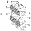
本発明の波長変換構造の斜視図を図1に示す。基板SU上に光散乱層SCと波長変換層WCが近接して交互に形成され、光散乱層SCと光変換層WCの断面は方形である。光散乱層SCは頂部に頂部反射層RUを備え、光変換層WCは底部に底部反射層RDを備える。以下に図1の構造を実現するプロセスを示す。 A perspective view of the wavelength conversion structure of the present invention is shown in FIG. The light scattering layers SC and the wavelength conversion layers WC are alternately formed adjacent to each other on the substrate SU, and the light scattering layers SC and the light conversion layers WC have a square cross section. The light scattering layer SC includes a top reflective layer RU at the top, and the light conversion layer WC includes a bottom reflective layer RD at the bottom. The process for realizing the structure of FIG. 1 is shown below.
平均径が約2μmの微粒子SPをネガレジストに20重量%混合し、これを基板SU上に厚さ20μmで塗布した。微粒子にはアルミナ、酸化チタン等の高屈折率の透明金属酸化物が適用可能である。これを露光、現像して図1に示したようにストライプ状にパターンニングして光散乱層SCとした。光散乱層SCの幅と間隙はいずれも25μmにし、光散乱層SCの高さは50μmにした。これにアルミニウムを蒸着すると、該アルミニウムは、光散乱層SCの頂部と間隙は平坦なため200nmの厚さで製膜され、光散乱層SCの側面はほぼ垂直なため前者よりも薄い100nmの厚さで成膜される。 Fine particles SP having an average diameter of about 2 μm were mixed with a negative resist in an amount of 20% by weight, and this was coated on the substrate SU with a thickness of 20 μm. A transparent metal oxide having a high refractive index such as alumina or titanium oxide can be applied to the fine particles. This was exposed and developed, and patterned into stripes as shown in FIG. 1 to obtain a light scattering layer SC. The width and gap of the light scattering layer SC were both 25 μm, and the height of the light scattering layer SC was 50 μm. When aluminum is vapor-deposited on this, the aluminum is formed with a thickness of 200 nm because the top and the gap of the light scattering layer SC are flat, and the side surface of the light scattering layer SC is almost vertical, so the thickness is 100 nm, which is thinner than the former. The film is formed.
これをウエットエッチングすると、光散乱層SCの頂部、間隙、側面のいずれのアルミニウム膜もほぼ同じ速度でエッチングされる。光散乱層SCの側面のアルミニウム膜が完全に消失するまでエッチングすると、光散乱層SCの頂部と間隙にはいずれも100nm程度の厚さのアルミニウム膜を残すことができる。100nm程度の厚さのアルミニウム膜は約85%の反射率を示し、これを反射層RLとした。反射層RLには高反射率の金属膜が好ましく、アルミニウムの外にも銀などが適用可能である。 When this is wet-etched, the aluminum film on the top, gap, and side surfaces of the light scattering layer SC is etched at substantially the same rate. When etching is performed until the aluminum film on the side surface of the light scattering layer SC completely disappears, an aluminum film having a thickness of about 100 nm can be left at the top and the gap of the light scattering layer SC. An aluminum film having a thickness of about 100 nm showed a reflectance of about 85%, and this was used as a reflective layer RL. The reflective layer RL is preferably a metal film having a high reflectance, and silver or the like can be applied in addition to aluminum.
スクリーン印刷用の透明インキに蛍光体FMを混合し、これを光散乱層SCの間隙に塗布して波長変換層WCとした。蛍光体FMにはクマリン6を用い、スクリーン印刷用の透明インキに0.3重量%混合した。クマリン6は有機低分子であり、透明インキ中に溶解して単分子分散するため、透明インキとクマリン6の混合物は透明である。即ち近接して交互に配置された光散乱層SCと波長変換層WCは、前者は光散乱性であるのに対し後者は透明である。 The phosphor FM was mixed with the transparent ink for screen printing, and this was applied to the gap between the light scattering layers SC to form the wavelength conversion layer WC. Coumarin 6 was used as phosphor FM, and 0.3% by weight was mixed with transparent ink for screen printing. Coumarin 6 is a low molecular organic molecule, and is dissolved in a transparent ink and monomolecularly dispersed. Therefore, the mixture of transparent ink and coumarin 6 is transparent. That is, the light scattering layer SC and the wavelength conversion layer WC that are alternately arranged in close proximity to each other are light scattering while the latter is transparent.
波長変換層WCに用いる蛍光体FMは、透明インキ等の透明媒体と蛍光体の混合物を透明にするために有機低分子若しくは量子ドットが適している。量子ドットとは、半導体の微粒子のことで、粒子の大きさを変えることによって発光の波長を変えることができる。尚ここで透明とは、光散乱性がなく光の直進性が良好なことを意味している。 As the phosphor FM used for the wavelength conversion layer WC, an organic low molecule or quantum dot is suitable for making a mixture of a transparent medium such as transparent ink and the phosphor transparent. Quantum dots are semiconductor fine particles, and the wavelength of light emission can be changed by changing the size of the particles. Here, the term “transparent” means that there is no light scattering property and the straightness of light is good.
波長変換層WCは蛍光体FMを含んでおり、蛍光体FMは可視波長の特定波長において吸収を示すため波長変換層WCは透明であっても無色透明ではない。有機低分子若しくは量子ドットは透明インキ中で集合体を形成してもその大きさが可視波長よりも十分に小さければ波長変換層WCは透明になるが、濃度消光による内部量子効率の低下を防ぐためには単一の分子に分かれた状態で分散している方が好ましい。ここで、濃度消光とは、粒子の濃度が高すぎた場合に、発光効率が低下する現象である。また、内部量子効率とは、蛍光体内部における発光効率をいう。 Since the wavelength conversion layer WC contains the phosphor FM, and the phosphor FM exhibits absorption at a specific wavelength of visible wavelengths, the wavelength conversion layer WC is transparent and not transparent. Although small organic molecules or even its size and quantum dots forms aggregates in a transparent ink in becomes sufficiently small when the wavelength conversion layer WC is more transparent than the visible wavelengths, the drop in the internal volume child efficiency due to concentration quenching In order to prevent this, it is preferable that the particles are dispersed in a single molecule state. Here, concentration quenching is a phenomenon in which the light emission efficiency decreases when the concentration of particles is too high. The internal quantum efficiency refers to the light emission efficiency inside the phosphor.
図2に示したように青色LED(Light Emitting Diode)BLEDを側面に備えたバックライトBLの上に本発明の波長変換構造を配置し、バックライトBLを点灯したところ緑色の蛍光が得られた。本発明の波長変換構造を上面に向けて発した蛍光の全光束量と、バックライトBLを前方に向けて発した光源光の全光束量を計測して比較したところ、前者は後者に対して約70%であった。 As shown in FIG. 2, when the wavelength conversion structure of the present invention is arranged on the backlight BL having a blue LED (Light Emitting Diode) BLED on the side surface and the backlight BL is turned on, green fluorescence is obtained. . When the total luminous flux of the fluorescence emitted toward the upper surface of the wavelength conversion structure of the present invention was measured and compared with the total luminous flux of the light source light emitted toward the front, the former was compared with the latter About 70%.
図2において、バックライトBLは、青色LED(BLED)が側面に配置された導光板LGの上にプリズムシートPRが載置されている。この他に拡散シート等も配置されるが、図2では省略されている。導光板の下に反射シートが配置している。 In FIG. 2, in the backlight BL, a prism sheet PR is placed on a light guide plate LG on which blue LEDs (BLEDs) are arranged on the side surfaces. In addition, a diffusion sheet or the like is also arranged, but is omitted in FIG. A reflective sheet is disposed under the light guide plate.
図2に示すように、導光板から出た光の一部EX1は底部反射層RDで反射するが、プリズムシートで再び反射され、光散乱層SCに入射し、その後光変換層WCに入射する。他の光EX2は光散乱層SCで一度後方散乱を受けるが、導光板LGの下の反射シートで反射し、再び光散乱層SCに入射し、その後光変換層WCに入射する。なお、反射はプリズムシートPR、反射シートのみでなく、導光板LG、拡散シート等の界面においても生ずる。 As shown in FIG. 2, a part of the light EX1 emitted from the light guide plate is reflected by the bottom reflective layer RD, but is reflected again by the prism sheet, enters the light scattering layer SC, and then enters the light conversion layer WC. . The other light EX2 is once backscattered by the light scattering layer SC, but is reflected by the reflection sheet below the light guide plate LG, enters the light scattering layer SC again, and then enters the light conversion layer WC. The reflection occurs not only at the prism sheet PR and the reflection sheet, but also at the interface of the light guide plate LG and the diffusion sheet.
図3は、光散乱層SCに入射した光EX3、EX4が散乱を受けながら波長変換層に入射する様子を示す断面模式図である。図4は、波長変換層WCにおいて、蛍光体FMによって波長変換を受けた光が表示面方向に出射する状態を示す断面模式図である。蛍光体FMからは色々な方向に光が放射される。FL1は、蛍光体FMからバックライト側に放射される光が底部反射層RDにおいて反射し、表示面方向に出て行く様子を示している。FL2は、蛍光体FMから光散乱層SC側に放射された光が光散乱層SCで散乱され、表示面方向に出射する様子を示している。FL3は、蛍光体FMから直接、表示面方向に光が出射する様子を示している。 FIG. 3 is a schematic cross-sectional view showing a state in which the light EX3 and EX4 incident on the light scattering layer SC are incident on the wavelength conversion layer while being scattered. FIG. 4 is a schematic cross-sectional view showing a state in which light subjected to wavelength conversion by the phosphor FM is emitted in the display surface direction in the wavelength conversion layer WC. Light is emitted from the phosphor FM in various directions. FL1 shows a state in which light emitted from the phosphor FM toward the backlight is reflected by the bottom reflective layer RD and exits in the display surface direction. FL2 shows a state in which light emitted from the phosphor FM toward the light scattering layer SC is scattered by the light scattering layer SC and emitted in the display surface direction. FL3 indicates a state in which light is emitted directly from the phosphor FM in the display surface direction.
実施例1の波長変換構造において、微粒子SPを混合したネガレジストの露光量を2倍に増大して光散乱層SCの断面形状を図5に示したように台形にした。光散乱層SCと波長変換層WCは断面がそれぞれ順テーパ、逆テーパとなり光散乱層SCと波長変換層WCの界面に傾斜を付与した。波長変換層WC内で生じた蛍光成分で側面に向かった成分は光散乱層SCに入射するが、光散乱層SCと波長変換層WCの界面が傾斜していることにより、平均的な出射方向が法線方向に偏る効果が得られる。 In the wavelength conversion structure of Example 1, the exposure amount of the negative resist mixed with the fine particles SP was doubled to make the cross-sectional shape of the light scattering layer SC trapezoidal as shown in FIG. The light scattering layer SC and the wavelength conversion layer WC have a forward taper and a reverse taper in cross section, respectively, and an inclination is given to the interface between the light scattering layer SC and the wavelength conversion layer WC. The fluorescent component generated in the wavelength conversion layer WC and directed toward the side surface is incident on the light scattering layer SC. However, since the interface between the light scattering layer SC and the wavelength conversion layer WC is inclined, an average emission direction is obtained. Can be obtained with an effect of biasing in the normal direction.
本発明の波長変換構造を用いる際、保護のため上面に透明媒体を積層して用いる場合がある。透明媒体と空気の界面では屈折が生じるが、例えば透明媒体の屈折率を1.5程度とすると、透明媒体の外側に出射するためには空気界面に対する入射角が45度以下であればよい。ここで入射角は、空気界面の法線を0度として定義した。本実施例では光散乱層SCと波長変換層WCを出る光の平均的な出射方向が法線方向に偏るので、透明媒体の外側に出射する割合が高まり効率が向上する。 When using the wavelength conversion structure of the present invention, a transparent medium may be laminated on the upper surface for protection. Refraction occurs at the interface between the transparent medium and the air. For example, when the refractive index of the transparent medium is about 1.5, the incident angle with respect to the air interface may be 45 degrees or less in order to emit light to the outside of the transparent medium. Here, the incident angle was defined with the normal of the air interface as 0 degree. In this embodiment, the average emission direction of the light exiting the light scattering layer SC and the wavelength conversion layer WC is biased in the normal direction, so that the ratio of emission to the outside of the transparent medium is increased and the efficiency is improved.
実施例1の波長変換構造において、図6に示したように光散乱層を第一の光散乱層SC1と第二の光散乱層SC2の積層体とし、第二の光散乱層SC2を基板SUから離れた側に配置し、第一の光散乱層SC1を基板SUに近接する側に配置した。光散乱層を第一の光散乱層SC1と第二の光散乱層SC2の積層体とするには、微粒子SPの混合比の異なるネガレジストを複数用意し、初めに混合比の低いネガレジストを塗布し、その上に混合比の高いネガを塗布し、その後一括して露光現像する。例えば微粒子SPの混合比が15重量%と30重量%のネガレジストを用意し、これを順次塗布しても良い。 In the wavelength conversion structure of Example 1, as shown in FIG. 6, the light scattering layer is a laminate of the first light scattering layer SC1 and the second light scattering layer SC2, and the second light scattering layer SC2 is used as the substrate SU. The first light scattering layer SC1 is disposed on the side close to the substrate SU. In order to make the light scattering layer a laminate of the first light scattering layer SC1 and the second light scattering layer SC2, a plurality of negative resists having different mixing ratios of the fine particles SP are prepared, and first a negative resist having a low mixing ratio is prepared. Apply, apply a negative with a high mixing ratio on it, and then expose and develop all at once. For example, a negative resist having a mixing ratio of the fine particles SP of 15% by weight and 30% by weight may be prepared and sequentially applied.
ネガレジスト中の微粒子SPの混合比が高いほど光拡散性が増大するが、これと共に後方散乱も増大する傾向にある。後方散乱とは光が入射側に散乱される現象であり、本発明の場合光は基板SU側から光散乱層SCに入射するため後方散乱により再び基板SU側に戻されることになる。本発明の波長変換構造には光リサイクル効果があるが、一回で光散乱層SC中に入射できればより効率が向上する。本実施例では入射側に相当する基板SU側の光散乱性を低くしたことにより一回で光散乱層SC中に入射し易くし、光散乱層SC中の奥まで入射した後に光散乱性のより高い層で散乱されて光変換層WCに向かう。以上により基板SUから光散乱層SCに光が入射する段階での入射効率が向上することにより、波長変換効率が向上する。 The light diffusibility increases as the mixing ratio of the fine particles SP in the negative resist increases, but the backscattering tends to increase along with this. Backscattering is a phenomenon in which light is scattered to the incident side, and in the case of the present invention, light is incident on the light scattering layer SC from the substrate SU side, and is therefore returned to the substrate SU side again by backscattering. Although the wavelength conversion structure of the present invention has a light recycling effect, if the light can be incident on the light scattering layer SC at one time, the efficiency is further improved. In this embodiment, the light scattering property on the substrate SU side corresponding to the incident side is lowered, so that it is easy to enter the light scattering layer SC at one time. Scattered by a higher layer and headed toward the light conversion layer WC. Thus, the wavelength conversion efficiency is improved by improving the incident efficiency at the stage where light is incident on the light scattering layer SC from the substrate SU.
あるいはまた、光散乱層を第一の光散乱層SC1と第二の光散乱層SC2と第三の光散乱層SC3の3層としても良い。これは、例えば微粒子SPの混合比が10重量%と20重量%と30重量%のネガレジストを用意し、これを順次塗布して露光することにより作成できる。 Alternatively, the light scattering layer may be three layers of the first light scattering layer SC1, the second light scattering layer SC2, and the third light scattering layer SC3. This can be created, for example, by preparing a negative resist having a mixing ratio of fine particles SP of 10% by weight, 20% by weight, and 30% by weight, and sequentially applying and applying the negative resist.
実施例1の波長変換構造において、図7に示したように光散乱層を第一の光散乱層SC1と第二の光散乱層SC2の積層体とした。具体的には、第一の光散乱層SC1にはネガレジストとの屈折率差が大きい第一の微粒子SP1を混合し、その第二の光散乱層SC2にはネガレジストとの屈折率差が小さい第二の微粒子SP2を混合した。 In the wavelength conversion structure of Example 1, as shown in FIG. 7, the light scattering layer was a laminate of the first light scattering layer SC1 and the second light scattering layer SC2. Specifically, the first light scattering layer SC1 is mixed with the first fine particles SP1 having a large refractive index difference from the negative resist, and the second light scattering layer SC2 has a refractive index difference from the negative resist. Small second fine particles SP2 were mixed.
第一の微粒子SP1と第二の微粒子SP2の組合せは、例えばシリカとアルミナでもよく、あるいはまたシリカと酸化チタンであっても良い。このような光散乱層を作成するには、初めに微粒子SP2を混合したネガレジストを塗布し、その上に第一の微粒子SP1を混合したネガレジストを塗布し、その後一括して露光現像する。 The combination of the first particle SP1 and the second particle SP2, for example, even silica and alumina rather good, Oh Rui may also be a silica and titanium oxide. In order to form such a light scattering layer, first, a negative resist mixed with the fine particles SP2 is applied, and then a negative resist mixed with the first fine particles SP1 is applied thereon, and then exposure and development are collectively performed.
微粒子とネガレジストとの屈折率差が大きいほど光拡散性が増大するが、これと共に後方散乱も増大する傾向にある。本実施例では入射側に相当する基板SU側の光散乱性を低くしたことにより一回で光散乱層SC中に入射し易くし、光散乱層SC中の奥まで入射した後に光散乱性のより高い層で散乱されて光変換層WCに向かう。 The light diffusibility increases as the refractive index difference between the fine particles and the negative resist increases, but the backscattering tends to increase along with this. In this embodiment, the light scattering property on the substrate SU side corresponding to the incident side is lowered, so that it is easy to enter the light scattering layer SC at one time. Scattered by a higher layer and headed toward the light conversion layer WC.
以上により基板SUから光散乱層に光が入射する段階での入射効率が向上することにより、波長変換効率が向上する。また、実施例3と異なり微粒子の混合比は一定でもよいので、微粒子を含有する複数のネガレジストの粘度はほぼ一定であり、塗布条件を変えることなく複数のネガレジストを塗布できるため光散乱層の作成が容易である。 As described above, the wavelength conversion efficiency is improved by improving the incident efficiency at the stage where light enters the light scattering layer from the substrate SU. In addition, since the mixing ratio of the fine particles may be constant unlike Example 3, the viscosity of the plurality of negative resists containing the fine particles is substantially constant, and a plurality of negative resists can be applied without changing the application conditions, so that the light scattering layer Is easy to create.
本実施例は、複数の層におけるネガレジストと微粒子の屈折率の差を利用するものであるから、レジストを第1層と第2層とで必ずしも同一にする必要は無く、レジストを第1層と第2層とで別な材料を使用してもよい。例えば、第1のレジストの屈折率と第1の微粒子の屈折率の差を第2のレジストと第2の微粒子の屈折率の差よりも大きくすることによって、以上で説明した本実施例と同様な効果を得ることができる。 Since this embodiment uses the difference in refractive index between the negative resist and the fine particles in a plurality of layers, the resist does not necessarily have to be the same between the first layer and the second layer. Different materials may be used for the second layer. For example, the difference between the refractive index of the first resist and the refractive index of the first fine particles is made larger than the difference of the refractive index of the second resist and the second fine particles, so that it is similar to the present embodiment described above. Effects can be obtained.
実施例2の波長変換構造において、図8に示したように波長変換層を赤色波長変換層RWC、緑色波長変換層GWCで構成した。また、赤色波長変換層RWCと緑色波長変換層GWCの他に光透過層TRを新たに配置し、赤色波長変換層RWCと緑色波長変換層GWCと光透過層TRを繰り返し配列した。赤色波長変換層RWCと緑色波長変換層GWCと光透過層TRは、スクリーン印刷により所定の光散乱層間の間隙のみに分布するように形成した。この他にも、ホトレジスト中に蛍光体を混合したものを塗布し、マスク露光を用いて所定の部分にのみ残るように露光して、その後現像してパターンニングしても良い。 In the wavelength conversion structure of Example 2, as shown in FIG. 8, the wavelength conversion layer was composed of a red wavelength conversion layer RWC and a green wavelength conversion layer GWC. In addition to the red wavelength conversion layer RWC and the green wavelength conversion layer GWC, a light transmission layer TR is newly disposed, and the red wavelength conversion layer RWC, the green wavelength conversion layer GWC, and the light transmission layer TR are repeatedly arranged. The red wavelength conversion layer RWC, the green wavelength conversion layer GWC, and the light transmission layer TR were formed by screen printing so as to be distributed only in gaps between predetermined light scattering layers. In addition to this, a mixture of a phosphor in a photoresist may be applied, exposed so as to remain only in a predetermined portion using mask exposure, and then developed and patterned.
緑色波長変換層GWCには実施例1の波長変換層WCと同様に蛍光体GFMとして、クマリン6を0.3重量%混合し、赤色波長変換層RWCには赤蛍光体RFMとして、DCMを0.3重量%混合した。また、光透過層TRには透明インキをそのまま用いた。光透過層TRは赤色波長変換層RWC、緑色波長変換層GWCと同様に光散乱層SCに近接しているが、光散乱層SC内から光透過層TRに移った時点で青色光は拡散光になっているため、赤色波長変換層RWCの赤色蛍光、緑色波長変換層GWCの緑色蛍光と同様の角度分布を有する。尚且つ、光透過層TRでは波長変換されないためバックライトの青色光がそのままの色相で出射される。赤色波長変換層RWCと緑色波長変換層GWCと光透過層TRからそれぞれ赤色、緑色、青色の光を出射することにより、青色のバックライト光
を白色光に変換することができた。尚且つ、各色ともほぼ同様の角度分布を有するため広い視野角の白色光が得られた。
Similarly to the wavelength conversion layer WC of Example 1, the green wavelength conversion layer GWC is mixed with 0.3% by weight of coumarin 6 as the phosphor GFM, and the red wavelength conversion layer RWC is DCM with 0% DCM as the red phosphor RFM. 3% by weight mixed. Further, transparent ink was used as it was for the light transmission layer TR. The light transmission layer TR is close to the light scattering layer SC in the same manner as the red wavelength conversion layer RWC and the green wavelength conversion layer GWC, but blue light is diffused when moving from the light scattering layer SC to the light transmission layer TR. Therefore, it has the same angle distribution as the red fluorescence of the red wavelength conversion layer RWC and the green fluorescence of the green wavelength conversion layer GWC. Further, since the wavelength is not converted in the light transmission layer TR, the blue light of the backlight is emitted in the same hue. By emitting red, green, and blue light from the red wavelength conversion layer RWC, the green wavelength conversion layer GWC, and the light transmission layer TR, respectively, the blue backlight light could be converted into white light. Moreover, since each color has almost the same angular distribution, white light with a wide viewing angle was obtained.
ここで、青色光は波長変換しないため蛍光体の内部量子効率による損失がなく、青色光が他の色の光よりも強くなる場合があり、白色光が青みを帯びる。その場合には例えば光透過層TRの占める面積を赤色波長変換層RWC、緑色波長変換層GWCよりも小さくすれば、白色光をより無彩色にすることができる。 Here, since the wavelength of blue light is not converted, there is no loss due to the internal quantum efficiency of the phosphor, the blue light may be stronger than the light of other colors, and the white light is bluish. In that case, for example, if the area occupied by the light transmission layer TR is smaller than the red wavelength conversion layer RWC and the green wavelength conversion layer GWC, the white light can be made more achromatic.
実施例5の波長変換構造において、光散乱層SCの平面分布を図9に示したように格子状とし、格子の中に赤色波長変換層RWCと緑色波長変換層GWCと光透過層TRを繰り返し配列した。実施例5において赤色波長変換層RWCと緑色波長変換層GWCと光透過層TRはストライプ状の配置であり、ストライプの伸長方向を含む方位とその垂直方向を含む方位では蛍光の極角分布に若干の違いが見られた。即ちこれは、ストライプの伸長方向の垂直方向では図2中にFL2で示した光散乱層SCによる後方散乱効果があるが、ストライプの伸長方向では光散乱層SCによる後方散乱効果がないために生じる。 In the wavelength conversion structure of the fifth embodiment, the planar distribution of the light scattering layer SC is a lattice as shown in FIG. 9, and the red wavelength conversion layer RWC, the green wavelength conversion layer GWC, and the light transmission layer TR are repeated in the lattice. Arranged. In Example 5, the red wavelength conversion layer RWC, the green wavelength conversion layer GWC, and the light transmission layer TR are arranged in a stripe shape, and the polar angle distribution of fluorescence is slightly in the orientation including the extension direction of the stripe and the orientation including the vertical direction. The difference was seen. That is, this occurs because there is a backscattering effect by the light scattering layer SC indicated by FL2 in FIG. 2 in the vertical direction of the stripe extension direction, but there is no backscattering effect by the light scattering layer SC in the stripe extension direction. .
本実施例では光散乱層SCの平面分布を格子状にしたことにより、いずれの方位でも光散乱層SCによる後方散乱効果が生じるようにした。これにより、ストライプの伸長方向を含む方位とその垂直方向を含む方位の蛍光の極角分布蛍光をほぼ同一にすることができた。 In this embodiment, the planar distribution of the light scattering layer SC is formed in a lattice shape, so that the back scattering effect by the light scattering layer SC occurs in any direction. As a result, it was possible to make the polar angle distribution fluorescence of the fluorescence of the orientation including the extension direction of the stripe and the orientation including the vertical direction substantially the same.
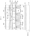
本実施例では、実施例6の波長変換構造を液晶表示装置に適用した。本実施例の液晶表示装置は図10に示したように主に第一の基板SU1と第二の基板SU2が液晶層LCを挟持して成り、第一の基板の周囲には周辺回路を有し、更にSU1には駆動用の回路が接続されている。本実施例の液晶表示装置の一画素の平面図を図11に示す。図11中に記載したBB’における断面図を図12に示す。 In this example, the wavelength conversion structure of Example 6 was applied to a liquid crystal display device. As shown in FIG. 10, the liquid crystal display device of this embodiment is mainly composed of a first substrate SU1 and a second substrate SU2 sandwiching a liquid crystal layer LC, and a peripheral circuit is provided around the first substrate. Further, a driving circuit is connected to SU1. A plan view of one pixel of the liquid crystal display device of this embodiment is shown in FIG. FIG. 12 is a cross-sectional view taken along the line BB ′ shown in FIG.
図12はアクティブ素子を含む断面であり、図10は図11中のAA’断面図である。図10および図12において、第一の基板SU1上には液晶層LCに近接する側より第一の配向膜AL1、ソース電極SE、第一の絶縁膜IL1、コモン電極CE、平坦化膜を兼ねた有機パッシベーション膜PAS、第二の絶縁膜IL2、信号配線SL、第三の絶縁膜IL3、走査配線GL、第四の絶縁膜IL4、ポリシリコン層PS、第一のアンダーコート膜UC1、第二のアンダーコート膜UC2を有する。第二の絶縁膜IL2は省略される場合もある。 FIG. 12 is a cross-section including an active element, and FIG. 10 is a cross-sectional view along AA ′ in FIG. 11. 10 and 12, the first alignment film AL1, the source electrode SE, the first insulating film IL1, the common electrode CE, and the planarizing film are also provided on the first substrate SU1 from the side close to the liquid crystal layer LC. Organic passivation film PAS, second insulating film IL2, signal wiring SL, third insulating film IL3, scanning wiring GL, fourth insulating film IL4, polysilicon layer PS, first undercoat film UC1, second Undercoat film UC2. The second insulating film IL2 may be omitted.
第二の基板SU2上には液晶層LCに近接する側より第二の配向膜AL2、第一の平坦化膜OC1、偏光層WGP、第二の平坦化膜OC2、波長変換構造が順次形成されている。波長変換構造は実施例6と同様の構成である。 On the second substrate SU2, a second alignment film AL2, a first planarizing film OC1, a polarizing layer WGP, a second planarizing film OC2, and a wavelength conversion structure are sequentially formed from the side close to the liquid crystal layer LC. ing. The wavelength conversion structure is the same as that of the sixth embodiment.
ソース電極SEとコモン電極CEは何れもITO(Indium Tin Oxide)から成り、両者は窒化珪素膜である第一の絶縁膜IL1を介して積層されており、ソース電極SEとコモン電極CEの重畳部は保持期間中において液晶層LCの電位を一定に保つ保持容量を形成する。ソース電極SEは一画素内に2本の櫛歯状構造を有し、コモン電極CEはべた平面状で、両者は窒化珪素膜である第一の絶縁膜IL1で隔てられており、ソース電極SEとコモン電極CEの間にはフリンジ電界が形成される。 The source electrode SE and the common electrode CE are both made of ITO (Indium Tin Oxide), and both are stacked via the first insulating film IL1 that is a silicon nitride film, and the overlapping portion of the source electrode SE and the common electrode CE Forms a storage capacitor that keeps the potential of the liquid crystal layer LC constant during the storage period. The source electrode SE has two comb-like structures in one pixel, the common electrode CE has a solid planar shape, and both are separated by a first insulating film IL1 that is a silicon nitride film. And a common electrode CE forms a fringe electric field.
このような方式の液晶表示装置はFFS(Fringe Field Switching)方式と呼ばれているが、FFSも液晶層LCの層平面に平行な方向に電界を印加する点で、IPS(In Plane Swiching)方式の一種である。IPS方式では、液晶層を駆動するための電極は第一の基板SU1上にのみ形成し、波長変換構造を備えた第二の基板SU2の構造をより簡略化できる。ソース電極SEはポリシリコン層PS、台座膜CAL、コンタクトホールCHを介して信号配線SLに接続されており、画像信号に応じた電位を液晶層LCに印加する。尚、台座膜CALは信号配線SLと同層である。 Such a liquid crystal display device is called an FFS (Fringe Field Switching) method, but the FFS also applies an IPS (In Plane Switching) method in that an electric field is applied in a direction parallel to the layer plane of the liquid crystal layer LC. It is a kind of. In the IPS system, an electrode for driving the liquid crystal layer is formed only on the first substrate SU1, and the structure of the second substrate SU2 having the wavelength conversion structure can be further simplified. The source electrode SE is connected to the signal wiring SL through the polysilicon layer PS, the pedestal film CAL, and the contact hole CH, and applies a potential corresponding to the image signal to the liquid crystal layer LC. The base film CAL is in the same layer as the signal wiring SL.
図11において、走査配線GLが第1の方向に延在して第2の方向に配列している。また、信号配線SLが第2の方向に延在して第1の方向に配列している。走査配線GLと信号配線SLで囲まれた領域に画素が形成されている。信号配線SLと走査配線GLは交差しており、その交差部近傍にポリシリコン層PSが形成されアクティブ素子として機能する。尚、第一の絶縁膜IL1とコモン電極CEは画素内においてコンタクトホールの近傍を除く全域に分布するため、図11において第一の絶縁膜IL1とコモン電極CEはコンタクトホールの周囲の空孔部をそれぞれ実線SINと一点鎖線CEで記載してある。 In FIG. 11, the scanning lines GL extend in the first direction and are arranged in the second direction. Further, the signal lines SL extend in the second direction and are arranged in the first direction. Pixels are formed in a region surrounded by the scanning wiring GL and the signal wiring SL. The signal wiring SL and the scanning wiring GL intersect each other, and a polysilicon layer PS is formed in the vicinity of the intersection to function as an active element. Since the first insulating film IL1 and the common electrode CE are distributed throughout the pixel except the vicinity of the contact hole, the first insulating film IL1 and the common electrode CE in FIG. Are indicated by a solid line SIN and a one-dot chain line CE, respectively.
液晶層LCは配向方向の誘電率がその垂直方向よりも大きい正の誘電率異方性を有し、高抵抗で尚且つ室温を含む広い温度範囲でネマチック相を示す。液晶層LCの電圧無印加時における配向状態はホモジニアス配向であり、図10中にその電圧無印加時における配向方向を円筒状の液晶分子LCMを用いて模式的に示してある。コモン電極CEとソース電極SEによるフリンジ電界が印加されると、液晶層LCの配向状態は方位が回転するように変化する。第一の配向膜AL1と第二の配向膜AL2は、ラビング法もしくは光配向法で配向処理する。液晶層LCには配向方向の誘電率がその垂直方向よりも小さい負の誘電率異方性の液晶も適用可能で、この場合は配向処理方向を図10中に記載した方向から90度ずらすべきである。 The liquid crystal layer LC has a positive dielectric anisotropy whose dielectric constant in the alignment direction is larger than that in the vertical direction, has high resistance, and exhibits a nematic phase in a wide temperature range including room temperature. The alignment state of the liquid crystal layer LC when no voltage is applied is homogeneous alignment, and the alignment direction when no voltage is applied is schematically shown in FIG. 10 using cylindrical liquid crystal molecules LCM. When a fringe electric field is applied by the common electrode CE and the source electrode SE, the alignment state of the liquid crystal layer LC changes so that the orientation rotates. The first alignment film AL1 and the second alignment film AL2 are subjected to an alignment process by a rubbing method or an optical alignment method. For the liquid crystal layer LC, a liquid crystal having negative dielectric anisotropy whose dielectric constant in the alignment direction is smaller than that in the vertical direction can also be applied. In this case, the alignment treatment direction should be shifted by 90 degrees from the direction described in FIG. It is.
第一の基板SU1の上層には偏光板PLが配置され、偏光板PLと偏光層WGPの透過軸は液晶パネルの法線方向から観察して直交するように設定されている。尚且つ、偏光層WGPの透過軸は液晶層LCの配向方向に平行である。以上のような偏光板PLと偏光層WGPと液晶層LCの軸配置により、電圧無印加時に暗表示が、電圧印加時に明表示が得られる。偏光板PLは異方性配向した色素を含み、偏光層WGPは50μmピッチの金属細線からなるワイヤーグリット型の偏光子である。 The polarizing plate PL is disposed on the upper layer of the first substrate SU1, and the transmission axes of the polarizing plate PL and the polarizing layer WGP are set so as to be orthogonal to each other when observed from the normal direction of the liquid crystal panel. In addition, the transmission axis of the polarizing layer WGP is parallel to the alignment direction of the liquid crystal layer LC. Due to the axial arrangement of the polarizing plate PL, the polarizing layer WGP, and the liquid crystal layer LC as described above, a dark display is obtained when no voltage is applied, and a bright display is obtained when a voltage is applied. The polarizing plate PL includes an anisotropically oriented dye, and the polarizing layer WGP is a wire grit type polarizer made of fine metal wires with a pitch of 50 μm.
第二の基板SU2上の波長変換構造は第一の基板SU1の画素と整合配置されている。図10の破線は画素境界を示しており、この破線上に光散乱層SCと信号配線SLが位置している。即ち波長変換構造中で光を発しない光散乱層SCは第一の基板SU1上の信号配線SLの直下に位置しており、赤色波長変換層RWCと緑色波長変換層GWCと光透過層TRはそれぞれ赤色画素RPXと緑色画素GPXと青色画素GPXのソース電極SEの直下に位置している。尚ここで赤色画素RPX、緑色画素GPX、青色画素GPXとは、それぞれ赤色、緑色、青色の画像信号に対応する電圧が印加される画素である。 The wavelength conversion structure on the second substrate SU2 is aligned with the pixels on the first substrate SU1. A broken line in FIG. 10 indicates a pixel boundary, and the light scattering layer SC and the signal wiring SL are located on the broken line. That is, the light scattering layer SC that does not emit light in the wavelength conversion structure is located immediately below the signal wiring SL on the first substrate SU1, and the red wavelength conversion layer RWC, the green wavelength conversion layer GWC, and the light transmission layer TR are The red pixel RPX, the green pixel GPX, and the blue pixel GPX are located immediately below the source electrode SE, respectively. Here, the red pixel RPX, the green pixel GPX, and the blue pixel GPX are pixels to which voltages corresponding to red, green, and blue image signals are applied, respectively.
第二の基板SU2の下方には青色LED(Light Emitting Diode)BLEDを側面に備えたバックライトBLを配置しており、赤色波長変換層RWCと緑色波長変換層GWCはこれを赤色光と緑色光に変換し、光透過層TRは波長を変換しないで青色光のまま透過する。第一の基板SU1上の画素の横幅と縦幅はそれぞれ17μm、51μmであるが、第二の基板SU2上の波長変換構造も繰返し周期もこれと同様にしており、図10に示したように両者が整合するように第一の基板SU1と第二の基板SU2を配置する。図10では整合する画素と赤色波長変換層RWC、緑色波長変換層GWC、光透過層TRを各一例ずつ破線で結んで示してある。これにより、赤色波長変換層RWC、緑色波長変換層GWC、光透過層TRを発した光は対応する画素に選択的に照射される。 A backlight BL having a blue LED (Light Emitting Diode) BLED on its side surface is disposed below the second substrate SU2, and the red wavelength conversion layer RWC and the green wavelength conversion layer GWC represent the red light and the green light. The light transmission layer TR transmits blue light as it is without converting the wavelength. The horizontal and vertical widths of the pixels on the first substrate SU1 are 17 μm and 51 μm, respectively, but the wavelength conversion structure and the repetition period on the second substrate SU2 are the same as shown in FIG. The first substrate SU1 and the second substrate SU2 are arranged so that they match. In FIG. 10, matching pixels, a red wavelength conversion layer RWC, a green wavelength conversion layer GWC, and a light transmission layer TR are shown by connecting each example with a broken line. Thereby, the light emitted from the red wavelength conversion layer RWC, the green wavelength conversion layer GWC, and the light transmission layer TR is selectively irradiated to the corresponding pixels.
このように本実施例の液晶表示装置は青色の光源光を波長変換して色表示するため、カラーフィルタを用いて白色光を着色する液晶表示装置に比較して高い効率が得られる。また、本実施例の波長変換構造は光リサイクル効果を有しており、光源光の角度分布にも特段の制限がなくコリメート性も必要としない。 As described above, since the liquid crystal display device of this embodiment performs color display by converting the wavelength of the blue light source light, higher efficiency can be obtained as compared with a liquid crystal display device that colors white light using a color filter. Further, the wavelength conversion structure of the present embodiment has a light recycling effect, and there is no particular limitation on the angular distribution of the light source light, and no collimating property is required.
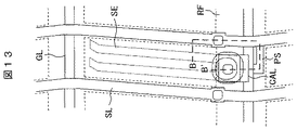
実施例7の液晶表示装置において、第一の基板SU1の信号配線SL、ゲート配線GLに反射防止層RFを形成した。実施例7の液晶表示装置では信号配線SLや走査配線GLで外光が反射されてコントラスト比が低下する場合がある。またポリシリコン層PSに外光が入射すると光電流が発生する場合があり、本来黒表示であるはずの画素に電圧が印加されるため、この場合にもコントラスト比が低下する。 In the liquid crystal display device of Example 7, the antireflection layer RF was formed on the signal wiring SL and the gate wiring GL of the first substrate SU1. In the liquid crystal display device according to the seventh embodiment, external light may be reflected by the signal lines SL and the scanning lines GL, and the contrast ratio may be reduced. Further, when external light is incident on the polysilicon layer PS, a photocurrent may be generated, and a voltage is applied to a pixel that should originally display black, so that the contrast ratio also decreases in this case.
本実施例の液晶表示装置の一画素の平面図を図13に示す。図13中に破線で示したように、反射防止層RFは信号配線SLと走査配線GLとポリシリコン層PSを覆うように分布する。反射防止層RFは例えば図16の断面図に示したように信号配線SLと走査配線GLとポリシリコン層PSよりも第一の基板SU1に近接する側に配置した酸化クロム層を有するクロム膜であっても良く、あるいはまた炭素粒子を分散しても良い。これにより、晴天時の屋外などの明るい環境での視認性が向上する効果が得られる。この他にも、信号配線SLや走査配線GLの第一の基板SU1に近接する面上に反射防止層を形成しても同様の効果が得られる。 A plan view of one pixel of the liquid crystal display device of this embodiment is shown in FIG. As indicated by a broken line in FIG. 13, the antireflection layer RF is distributed so as to cover the signal wiring SL, the scanning wiring GL, and the polysilicon layer PS. The antireflection layer RF is, for example, a chromium film having a chromium oxide layer disposed on the side closer to the first substrate SU1 than the signal wiring SL, the scanning wiring GL, and the polysilicon layer PS as shown in the sectional view of FIG. Alternatively, carbon particles may be dispersed. Thereby, the effect which the visibility in bright environments, such as the outdoors at the time of fine weather, improves is acquired. In addition, the same effect can be obtained by forming an antireflection layer on the surface of the signal wiring SL and the scanning wiring GL adjacent to the first substrate SU1.
実施例7の液晶表示装置において、外部から入射した光による蛍光の発生を防ぐための外光励起防止層を配置した。本発明の波長変換層は第一の偏光板PL、液晶層LC及び第二の偏光板WGPの下方に位置する。そのため、外部からの光が波長変換層に入射する場合、第一の偏光板PL1、液晶層LC及び第二の偏光層WGPを通過するので、画像情報に対応した強度で入射する。しかしながら、赤色波長変換層RWCと緑色波長変換層GWCは蛍光を発光するのに対し光透過層TRは蛍光を発光しないため、日中の屋外などでは外光入射により色相の変化等の画質劣化が生じる場合がある。 In the liquid crystal display device of Example 7, an external light excitation prevention layer for preventing generation of fluorescence due to light incident from the outside was disposed. The wavelength conversion layer of the present invention is located below the first polarizing plate PL, the liquid crystal layer LC, and the second polarizing plate WGP. Therefore, when light from the outside enters the wavelength conversion layer, it passes through the first polarizing plate PL1, the liquid crystal layer LC, and the second polarizing layer WGP, and therefore enters with the intensity corresponding to the image information. However, since the red wavelength conversion layer RWC and the green wavelength conversion layer GWC emit fluorescence, the light transmission layer TR does not emit fluorescence. Therefore, image quality degradation such as a hue change is caused by the incidence of external light in the daytime outdoors. May occur.
本実施例の液晶表示装置の断面図を図14に示す。緑色波長変換層GWCの上層には黄色カラーフィルタYCを積層し、赤色波長変換層RWCの上層には赤色カラーフィルタRCを積層した。緑色波長変換層GWCは青色の光で励起されるが、その上に青色の光を吸収する黄色カラーフィルタYCを積層したことにより青色光の入射による励起を防止することができる。赤色波長変換層RWCは青色と緑色の光で励起されるが、その上に青色と緑色の光を吸収する赤色カラーフィルタRCを積層したことにより青色と緑色の光の入射による励起を防止することができる。これにより、日中の屋外などでも画質の劣化を防ぐことができる。 A cross-sectional view of the liquid crystal display device of this example is shown in FIG. A yellow color filter YC was stacked on the green wavelength conversion layer GWC, and a red color filter RC was stacked on the red wavelength conversion layer RWC. The green wavelength conversion layer GWC is excited by blue light. However, excitation by blue light incidence can be prevented by stacking a yellow color filter YC that absorbs blue light thereon. The red wavelength conversion layer RWC is excited by blue and green light, and a red color filter RC that absorbs blue and green light is laminated thereon to prevent excitation due to incidence of blue and green light. Can do. As a result, it is possible to prevent deterioration in image quality even outdoors during the daytime.
図15は本実施例を示す断面図である。本実施例では、実施例7の液晶表示装置において、バックライトBLに近紫外光を発するLED(UVLED)を用いた。光透過層TRの代わりに青色蛍光体BFMを含有する青色波長変換層BWCを用い、青色波長変換層BWCで光源光を波長変換して青色光を表示した。実施例5のように青色光を波長変換しない場合には青色光のみ蛍光体の内部量子効率による損失がないため、青色光が他の色の光よりも強くなる場合があった。本実施例では青色光も波長変換するため、青色波長変換層BWCと緑色波長変換層GWCと赤色波長変換層RWCの面積比を等しくしても白を無彩色に近づけることができる。 FIG. 15 is a sectional view showing the present embodiment. In this example, in the liquid crystal display device of Example 7, an LED (UVLED) emitting near-ultraviolet light was used for the backlight BL. A blue wavelength conversion layer BWC containing a blue phosphor BFM was used instead of the light transmission layer TR, and the light source light was wavelength-converted by the blue wavelength conversion layer BWC to display blue light. When blue light is not wavelength-converted as in Example 5, there is no loss due to the internal quantum efficiency of only the blue light, and thus the blue light may be stronger than the light of other colors. In this embodiment, since the wavelength of blue light is also converted, white can be brought closer to an achromatic color even if the area ratios of the blue wavelength conversion layer BWC, the green wavelength conversion layer GWC, and the red wavelength conversion layer RWC are equal.
WC…波長変換層、 RWC…赤色波長変換層、 GWC…緑色波長変換層、 BWC…青色波長変換層、 FM…蛍光体、 SC…光散乱層、 SP…微粒子、 RD…底部反射層、 RU…頂部反射層、 BL…バックライト、 BLED…青LED、 UVLED…紫外線放射LED、 LG…導光板、 PR…プリズムシート、 TR…光透過層、 RPX…赤色画素、 GPX…緑画素、 BPX…青色画素、 PL…偏光板、 WGP…偏光層、 PS…ポリシリコン、 第1アンダーコート膜 UC1…第1アンダーコート膜、 UC2…第2アンダーコート膜、 SL…信号配線、 SE…画素電極、 CE…コモン電極、 CAL…台座膜、 GL…走査線、 IL1…第一絶縁膜、 SIN…第1絶縁膜のホール、 IL2…第2絶縁膜、 IL3…第3絶縁膜、 IL4…第4絶縁膜、 PAS…有機パッシベーション膜、 CH…コンタクトホール、 LC…液晶層、 LCM…液晶分子、 AL1…第1の配向膜、 AL2…第2の配向膜、 OC1…第1のオーバーコート膜、 OC2…第2のオーバーコート膜、 RF…反射防止層、 RC…赤色カラーフィルタ、 YC…黄色カラーフィルタ WC ... Wavelength conversion layer, RWC ... Red wavelength conversion layer, GWC ... Green wavelength conversion layer, BWC ... Blue wavelength conversion layer, FM ... Phosphor, SC ... Light scattering layer, SP ... Fine particle, RD ... Bottom reflection layer, RU ... Top reflective layer, BL ... Backlight, BLED ... Blue LED, UVLED ... UV radiation LED, LG ... Light guide plate, PR ... Prism sheet, TR ... Light transmission layer, RPX ... Red pixel, GPX ... Green pixel, BPX ... Blue pixel , PL: polarizing plate, WGP: polarizing layer, PS: polysilicon, first undercoat film UC1: first undercoat film, UC2: second undercoat film, SL: signal wiring, SE: pixel electrode, CE: common Electrode, CAL: Base film, GL: Scan line, IL1: First insulating film, SIN: Hole in first insulating film, IL2: Second insulating film, I L3 ... third insulating film, IL4 ... fourth insulating film, PAS ... organic passivation film, CH ... contact hole, LC ... liquid crystal layer, LCM ... liquid crystal molecule, AL1 ... first alignment film, AL2 ... second alignment film , OC1 ... first overcoat film, OC2 ... second overcoat film, RF ... antireflection layer, RC ... red color filter, YC ... yellow color filter
Claims (14)
前記表示パネルは、前記バックライトと対向する基板を有し、前記基板の前記表示面と平行な面において、画素毎に波長変換層を有し、前記波長変換層と波長変換層の間に光散乱層を有し、
前記波長変換層は蛍光体を有し、
前記光散乱層は微粒子を有し、
前記波長変換層の前記バックライト側は反射層を有し、
前記光散乱層の前記表示面側は反射層を有し、
前記波長変換層のバックライト側の反射層は、前記バックライトから出射する光を前記バックライト側へ反射し、
前記波長変換層は前記光散乱層から入射した光の波長を変換することを特徴とする表示装置。 A display panel having a display surface and a display device having a backlight,
The display panel includes a substrate facing the backlight, and includes a wavelength conversion layer for each pixel on a surface parallel to the display surface of the substrate, and light is transmitted between the wavelength conversion layer and the wavelength conversion layer. Has a scattering layer,
The wavelength conversion layer has a phosphor,
The light scattering layer has fine particles,
The backlight side of the wavelength conversion layer has a reflective layer,
The display surface side of the light scattering layer have a reflective layer,
The reflection layer on the backlight side of the wavelength conversion layer reflects light emitted from the backlight to the backlight side,
The display device, wherein the wavelength conversion layer converts a wavelength of light incident from the light scattering layer .
台形であることを特徴とする請求項1に記載の表示装置。 In the cross section of the wavelength conversion layer, the width on the display surface side is larger than the width on the backlight side,
The display device according to claim 1, wherein the display device is trapezoidal.
前記レジストの屈折率と前記第1の微粒子の屈折率の差は、前記レジストの屈折率と前記第2の微粒子の屈折率の差よりも大きいことを特徴とする請求項3に記載の表示装置。 In the light scattering layer, a first light scattering layer in which first fine particles are dispersed in a resist is formed on the display surface side, and a second light scattering layer in which second fine particles are dispersed in the resist. Formed on the backlight side,
4. The display device according to claim 3, wherein a difference between a refractive index of the resist and a refractive index of the first fine particles is larger than a difference between a refractive index of the resist and a refractive index of the second fine particles. .
前記表示パネルは、前記バックライトと対向する基板を有し、前記基板の前記表示面と平行な面において、赤色を発光する波長変換層と、緑色を発光する波長変換層と、光透過層を有し、
前記赤色を発光する波長変換層と、前記緑色を発光する波長変換層と、前記光透過層の間には光散乱層が形成され、
前記赤色を発光する波長変換層と、前記緑色を発光する波長変換層と、前記光透過層の前記バックライト側は反射層を有し、
前記光散乱層は前記表示面側に反射層を有し、
前記バックライトの光源は青色発光LEDであり、
前記波長変換層のバックライト側の反射層は、前記バックライトから出射する前記青色発光LEDの光を前記バックライト側へ反射し、
前記波長変換層は前記光散乱層から入射した光の波長を変換することを特徴とする表示装置。 A display panel having a display surface and a display device having a backlight,
The display panel includes a substrate facing the backlight, and includes a wavelength conversion layer that emits red light, a wavelength conversion layer that emits green light, and a light transmission layer on a surface parallel to the display surface of the substrate. Have
A light scattering layer is formed between the wavelength conversion layer emitting red light, the wavelength conversion layer emitting green light, and the light transmission layer,
The wavelength conversion layer that emits red light, the wavelength conversion layer that emits green light, and the backlight side of the light transmission layer has a reflective layer,
The light scattering layer has a reflective layer on the display surface side,
The backlight light source is a blue emitting LED,
The reflective layer on the backlight side of the wavelength conversion layer reflects the light of the blue light emitting LED emitted from the backlight to the backlight side,
Display the wavelength conversion layer is characterized that you converting a wavelength of light incident from the light scattering layer.
前記表示パネルは、前記バックライトと対向する基板を有し、前記基板の前記表示面と平行な面において、赤色を発光する波長変換層と、緑色を発光する波長変換層と、青色を発光する波長変換層を有し、
前記赤色を発光する波長変換層と、前記緑色を発光する波長変換層と、前記青色を発光する波長変換層の間には光散乱層が形成され、
前記赤色を発光する波長変換層と、前記緑色を発光する波長変換層と、前記青色を発光する波長変換層の前記バックライト側は反射層を有し、
前記光散乱層は前記表示面側に反射層を有し、
前記バックライトの光源は紫外線発光LEDであり、
前記波長変換層のバックライト側の反射層は、前記バックライトから出射する前記紫外線発光LEDの光を前記バックライト側へ反射し、
前記波長変換層は前記光散乱層から入射した光の波長を変換することを特徴とする表示装置。 A display panel having a display surface and a display device having a backlight,
The display panel includes a substrate facing the backlight, and emits blue light on a wavelength conversion layer that emits red light, a wavelength conversion layer that emits green light, on a surface parallel to the display surface of the substrate. Having a wavelength conversion layer,
A light scattering layer is formed between the wavelength conversion layer that emits red, the wavelength conversion layer that emits green, and the wavelength conversion layer that emits blue.
The wavelength conversion layer that emits red light, the wavelength conversion layer that emits green light, and the backlight side of the wavelength conversion layer that emits blue light have a reflective layer,
The light scattering layer has a reflective layer on the display surface side,
The backlight light source Ri ultraviolet emitting LED der,
The reflection layer on the backlight side of the wavelength conversion layer reflects the light of the ultraviolet light emitting LED emitted from the backlight to the backlight side,
Display the wavelength conversion layer is characterized that you converting a wavelength of light incident from the light scattering layer.
前記第2の基板は、前記バックライトと対向し、
前記第1の基板には走査配線と信号配線に囲まれた領域に画素が形成され、
前記画素にはTFTと接続した画素電極が形成され、
前記第2の基板には前記画素に対応して波長変換層が形成され、
前記波長変換層と前記波長変換層の間には光散乱層が形成され、
前記波長変換層は蛍光体を有し、
前記波長変換層の前記バックライト側には反射層が形成され、
前記光散乱層の前記液晶層側には反射層が形成され、
前記波長変換層のバックライト側の反射層は、前記バックライトから出射する光を前記バックライト側へ反射し、
前記波長変換層は前記光散乱層から入射した光の波長を変換することを特徴とする液晶表示装置。 A liquid crystal display device having a liquid crystal display panel in which a liquid crystal layer is sandwiched between a first substrate and a second substrate and a backlight,
The second substrate is opposed to the backlight;
In the first substrate, pixels are formed in a region surrounded by scanning wiring and signal wiring,
A pixel electrode connected to the TFT is formed on the pixel,
A wavelength conversion layer is formed on the second substrate corresponding to the pixels,
A light scattering layer is formed between the wavelength conversion layer and the wavelength conversion layer,
The wavelength conversion layer has a phosphor,
A reflective layer is formed on the backlight side of the wavelength conversion layer,
A reflective layer is formed on the liquid crystal layer side of the light scattering layer,
The reflection layer on the backlight side of the wavelength conversion layer reflects light emitted from the backlight to the backlight side,
The liquid crystal display device, wherein the wavelength conversion layer converts a wavelength of light incident from the light scattering layer .
前記第1の基板には走査配線と信号配線に囲まれた領域毎に赤画素、緑画素、青画素が形成され、
前記赤画素、前記緑画素、前記青画素にはTFTと接続した画素電極が形成され、
前記第2の基板は、前記バックライトと対向し、
前記第2の基板には前記赤画素、前記緑画素、前記青画素に対応して赤色を発光する波長変換層、緑色を発光する波長変換層、光透過層が形成され、
前記赤色を発光する波長変換層、前記緑色を発光する波長変換層、前記光透過層の前記バックライト側には光反射層が形成され、
前記赤色を発光する波長変換層、前記緑色を発光する波長変換層、前記光透過層の間には光散乱層が形成され、
前記光散乱層の前記液晶層側には反射層が形成され、
前記バックライトの光源は青色を発光するLEDであり、
前記波長変換層のバックライト側の光反射層は、前記バックライトから出射する前記LEDの光を前記バックライト側へ反射し、
前記波長変換層は前記光散乱層から入射した光の波長を変換することを特徴とする液晶表示装置。 A liquid crystal display device having a liquid crystal display panel in which a liquid crystal layer is sandwiched between a first substrate and a second substrate and a backlight,
A red pixel, a green pixel, and a blue pixel are formed in each region surrounded by the scanning wiring and the signal wiring on the first substrate.
A pixel electrode connected to the TFT is formed on the red pixel, the green pixel, and the blue pixel,
The second substrate is opposed to the backlight;
A wavelength conversion layer that emits red, a wavelength conversion layer that emits green, and a light transmission layer are formed on the second substrate in correspondence with the red pixel, the green pixel, and the blue pixel,
A wavelength conversion layer emitting red light, a wavelength conversion layer emitting green light, a light reflection layer is formed on the backlight side of the light transmission layer,
A light scattering layer is formed between the wavelength conversion layer emitting red light, the wavelength conversion layer emitting green light, and the light transmission layer,
A reflective layer is formed on the liquid crystal layer side of the light scattering layer,
The backlight light source is a LED that emits blue,
The light reflecting layer on the backlight side of the wavelength conversion layer reflects the LED light emitted from the backlight to the backlight side,
The liquid crystal display device, wherein the wavelength conversion layer converts a wavelength of light incident from the light scattering layer .
前記第1の基板には走査配線と信号配線に囲まれた領域毎に赤画素、緑画素、青画素が形成され、
前記赤画素、前記緑画素、前記青画素にはTFTと接続した画素電極が形成され、
前記第2の基板は、前記バックライトと対向し、
前記第2の基板には前記赤画素、前記緑画素、前記青画素に対応して赤色を発光する波長変換層、緑色を発光する波長変換層、青色を発光する波長変換層が形成され、
前記赤色を発光する波長変換層、前記緑色を発光する波長変換層、前記青色を発光する波長変換層の前記バックライト側には光反射層が形成され、
前記赤色を発光する波長変換層、前記緑色を発光する波長変換層、前記青色を発光する波長変換層の間には光散乱層が形成され、
前記光散乱層の前記液晶層側には反射層が形成され、
前記バックライトの光源は紫外線を発光するLEDであり、
前記波長変換層のバックライト側の光反射層は、前記バックライトから出射する前記LEDの光を前記バックライト側へ反射し、
前記波長変換層は前記光散乱層から入射した光の波長を変換することを特徴とする液晶表示装置。 A liquid crystal display device having a liquid crystal display panel in which a liquid crystal layer is sandwiched between a first substrate and a second substrate and a backlight,
A red pixel, a green pixel, and a blue pixel are formed in each region surrounded by the scanning wiring and the signal wiring on the first substrate.
A pixel electrode connected to the TFT is formed on the red pixel, the green pixel, and the blue pixel,
The second substrate is opposed to the backlight;
A wavelength conversion layer that emits red light corresponding to the red pixel, the green pixel, and the blue pixel, a wavelength conversion layer that emits green light, and a wavelength conversion layer that emits blue light are formed on the second substrate,
A light reflection layer is formed on the backlight side of the wavelength conversion layer that emits red, the wavelength conversion layer that emits green, and the wavelength conversion layer that emits blue.
A light scattering layer is formed between the wavelength conversion layer emitting red, the wavelength conversion layer emitting green, and the wavelength conversion layer emitting blue.
A reflective layer is formed on the liquid crystal layer side of the light scattering layer,
The light source of the backlight is an LED that emits ultraviolet rays ,
The light reflecting layer on the backlight side of the wavelength conversion layer reflects the LED light emitted from the backlight to the backlight side,
The liquid crystal display device, wherein the wavelength conversion layer converts a wavelength of light incident from the light scattering layer .
Priority Applications (2)
| Application Number | Priority Date | Filing Date | Title |
|---|---|---|---|
| JP2014108205A JP6367001B2 (en) | 2014-05-26 | 2014-05-26 | Display device and liquid crystal display device |
| US14/721,197 US9857642B2 (en) | 2014-05-26 | 2015-05-26 | Display device and liquid crystal display device |
Applications Claiming Priority (1)
| Application Number | Priority Date | Filing Date | Title |
|---|---|---|---|
| JP2014108205A JP6367001B2 (en) | 2014-05-26 | 2014-05-26 | Display device and liquid crystal display device |
Publications (3)
| Publication Number | Publication Date |
|---|---|
| JP2015225114A JP2015225114A (en) | 2015-12-14 |
| JP2015225114A5 JP2015225114A5 (en) | 2017-06-22 |
| JP6367001B2 true JP6367001B2 (en) | 2018-08-01 |
Family
ID=54555948
Family Applications (1)
| Application Number | Title | Priority Date | Filing Date |
|---|---|---|---|
| JP2014108205A Active JP6367001B2 (en) | 2014-05-26 | 2014-05-26 | Display device and liquid crystal display device |
Country Status (2)
| Country | Link |
|---|---|
| US (1) | US9857642B2 (en) |
| JP (1) | JP6367001B2 (en) |
Families Citing this family (8)
| Publication number | Priority date | Publication date | Assignee | Title |
|---|---|---|---|---|
| CN105388668B (en) | 2015-12-25 | 2018-06-22 | 武汉华星光电技术有限公司 | Reflection type liquid crystal panel and display device |
| US10955702B2 (en) * | 2017-01-20 | 2021-03-23 | Suzhou Xingshuo Nanotech Co., Ltd. | Photoluminescent nanocrystals based color liquid crystal display for switchable two dimensional/three dimensional displays with wider color gamut and high energy efficiency |
| DE102017107939A1 (en) * | 2017-04-12 | 2018-10-18 | Osram Opto Semiconductors Gmbh | Method for producing an optoelectronic component and optoelectronic component |
| CN109283737B (en) * | 2017-07-21 | 2021-06-18 | 行家光电股份有限公司 | Light emitting device with asymmetric structure, backlight module comprising same and manufacturing method of light emitting device |
| KR102617876B1 (en) * | 2018-02-01 | 2023-12-27 | 삼성디스플레이 주식회사 | Color conversion panel, display device including the same, and method of manufacturing the same |
| WO2019177755A1 (en) * | 2018-03-13 | 2019-09-19 | Apple Inc. | Displays with direct-lit backlight units |
| US20220216379A1 (en) * | 2019-05-13 | 2022-07-07 | Dai Nippon Printing Co., Ltd. | Barrier film, wavelength conversion sheet using barrier film, and display device using wavelength conversion sheet |
| KR20230099853A (en) * | 2021-12-28 | 2023-07-05 | 엘지디스플레이 주식회사 | Backlight unit and display device |
Family Cites Families (9)
| Publication number | Priority date | Publication date | Assignee | Title |
|---|---|---|---|---|
| JP3695393B2 (en) * | 2000-03-21 | 2005-09-14 | 株式会社日立製作所 | Liquid crystal display device |
| JP3793915B2 (en) * | 2001-02-28 | 2006-07-05 | 株式会社日立製作所 | Liquid crystal display |
| JP5112230B2 (en) * | 2008-09-10 | 2013-01-09 | 株式会社ジャパンディスプレイイースト | Liquid crystal display |
| TWI405005B (en) * | 2009-01-23 | 2013-08-11 | Au Optronics Corp | Display device, manufacturing method thereof, and a color adjusting method used thereon |
| JP2010198940A (en) * | 2009-02-26 | 2010-09-09 | Kuraray Co Ltd | Lens sheet for backlight |
| JP2015043256A (en) * | 2011-12-21 | 2015-03-05 | シャープ株式会社 | Optical substrate, manufacturing method of the same, light emitting element, liquid crystal element, display device, liquid crystal device, and lighting device |
| JP2013196854A (en) * | 2012-03-16 | 2013-09-30 | Sharp Corp | Fluorescent substrate and display device including the same |
| JP2013235141A (en) * | 2012-05-09 | 2013-11-21 | Sharp Corp | Color liquid crystal display unit |
| JP2013246303A (en) | 2012-05-25 | 2013-12-09 | Sharp Corp | Color conversion substrate, illumination device and color display |
-
2014
- 2014-05-26 JP JP2014108205A patent/JP6367001B2/en active Active
-
2015
- 2015-05-26 US US14/721,197 patent/US9857642B2/en active Active
Also Published As
| Publication number | Publication date |
|---|---|
| US9857642B2 (en) | 2018-01-02 |
| JP2015225114A (en) | 2015-12-14 |
| US20150338705A1 (en) | 2015-11-26 |
Similar Documents
| Publication | Publication Date | Title |
|---|---|---|
| JP6367001B2 (en) | Display device and liquid crystal display device | |
| US10620478B2 (en) | Photoluminescent display device and method for manufacturing the same | |
| JP4851908B2 (en) | Liquid crystal display | |
| JP3487782B2 (en) | Liquid crystal display | |
| US6469755B1 (en) | Illuminating arrangement with reflector having inclined irregularities or corrugations | |
| JP5112230B2 (en) | Liquid crystal display | |
| JP2015138123A (en) | display device | |
| KR20120015190A (en) | Reflective display device | |
| JP2016142894A (en) | Display device | |
| CN108957830B (en) | Display device, control method of display device, and display apparatus | |
| US10761362B2 (en) | Display panel and display device | |
| JP2013235141A (en) | Color liquid crystal display unit | |
| US10802201B2 (en) | Display device which prevents formation of parasitic capacitor in a pixel | |
| JP2001337320A (en) | Semitransmissive liquid crystal display element | |
| US10558083B2 (en) | Liquid crystal display module and liquid crystal display device | |
| JP2013104888A (en) | Display device | |
| JP2014067580A (en) | Light source device and display device | |
| US10816846B2 (en) | Display device, display panel, color filter substrate and color filter | |
| JP2020091419A (en) | Display device | |
| US9964688B2 (en) | Liquid crystal display device | |
| JP2010122435A (en) | Liquid crystal display device, backlight unit, and optical filter | |
| JP2014010398A (en) | Display device | |
| JP2006012722A (en) | Backlight device and liquid crystal display equipped with it | |
| JP5454443B2 (en) | Liquid crystal display | |
| JP2000275629A (en) | Liquid crystal display device and its production |
Legal Events
| Date | Code | Title | Description |
|---|---|---|---|
| A521 | Request for written amendment filed |
Free format text: JAPANESE INTERMEDIATE CODE: A523 Effective date: 20170515 |
|
| A621 | Written request for application examination |
Free format text: JAPANESE INTERMEDIATE CODE: A621 Effective date: 20170515 |
|
| A131 | Notification of reasons for refusal |
Free format text: JAPANESE INTERMEDIATE CODE: A131 Effective date: 20180130 |
|
| A977 | Report on retrieval |
Free format text: JAPANESE INTERMEDIATE CODE: A971007 Effective date: 20180131 |
|
| A521 | Request for written amendment filed |
Free format text: JAPANESE INTERMEDIATE CODE: A523 Effective date: 20180330 |
|
| TRDD | Decision of grant or rejection written | ||
| A01 | Written decision to grant a patent or to grant a registration (utility model) |
Free format text: JAPANESE INTERMEDIATE CODE: A01 Effective date: 20180605 |
|
| A61 | First payment of annual fees (during grant procedure) |
Free format text: JAPANESE INTERMEDIATE CODE: A61 Effective date: 20180704 |
|
| R150 | Certificate of patent or registration of utility model |
Ref document number: 6367001 Country of ref document: JP Free format text: JAPANESE INTERMEDIATE CODE: R150 |
|
| R250 | Receipt of annual fees |
Free format text: JAPANESE INTERMEDIATE CODE: R250 |
|
| R250 | Receipt of annual fees |
Free format text: JAPANESE INTERMEDIATE CODE: R250 |
|
| R250 | Receipt of annual fees |
Free format text: JAPANESE INTERMEDIATE CODE: R250 |