JP6363199B2 - Passive positioning using round-trip time information - Google Patents
Passive positioning using round-trip time information Download PDFInfo
- Publication number
- JP6363199B2 JP6363199B2 JP2016538944A JP2016538944A JP6363199B2 JP 6363199 B2 JP6363199 B2 JP 6363199B2 JP 2016538944 A JP2016538944 A JP 2016538944A JP 2016538944 A JP2016538944 A JP 2016538944A JP 6363199 B2 JP6363199 B2 JP 6363199B2
- Authority
- JP
- Japan
- Prior art keywords
- message
- access point
- time
- rtt
- sifs
- Prior art date
- Legal status (The legal status is an assumption and is not a legal conclusion. Google has not performed a legal analysis and makes no representation as to the accuracy of the status listed.)
- Expired - Fee Related
Links
Images


Classifications
-
- H—ELECTRICITY
- H04—ELECTRIC COMMUNICATION TECHNIQUE
- H04W—WIRELESS COMMUNICATION NETWORKS
- H04W64/00—Locating users or terminals or network equipment for network management purposes, e.g. mobility management
-
- G—PHYSICS
- G01—MEASURING; TESTING
- G01S—RADIO DIRECTION-FINDING; RADIO NAVIGATION; DETERMINING DISTANCE OR VELOCITY BY USE OF RADIO WAVES; LOCATING OR PRESENCE-DETECTING BY USE OF THE REFLECTION OR RERADIATION OF RADIO WAVES; ANALOGOUS ARRANGEMENTS USING OTHER WAVES
- G01S5/00—Position-fixing by co-ordinating two or more direction or position line determinations; Position-fixing by co-ordinating two or more distance determinations
- G01S5/0009—Transmission of position information to remote stations
- G01S5/0081—Transmission between base stations
-
- G—PHYSICS
- G01—MEASURING; TESTING
- G01S—RADIO DIRECTION-FINDING; RADIO NAVIGATION; DETERMINING DISTANCE OR VELOCITY BY USE OF RADIO WAVES; LOCATING OR PRESENCE-DETECTING BY USE OF THE REFLECTION OR RERADIATION OF RADIO WAVES; ANALOGOUS ARRANGEMENTS USING OTHER WAVES
- G01S5/00—Position-fixing by co-ordinating two or more direction or position line determinations; Position-fixing by co-ordinating two or more distance determinations
- G01S5/02—Position-fixing by co-ordinating two or more direction or position line determinations; Position-fixing by co-ordinating two or more distance determinations using radio waves
- G01S5/0205—Details
- G01S5/021—Calibration, monitoring or correction
-
- G—PHYSICS
- G01—MEASURING; TESTING
- G01S—RADIO DIRECTION-FINDING; RADIO NAVIGATION; DETERMINING DISTANCE OR VELOCITY BY USE OF RADIO WAVES; LOCATING OR PRESENCE-DETECTING BY USE OF THE REFLECTION OR RERADIATION OF RADIO WAVES; ANALOGOUS ARRANGEMENTS USING OTHER WAVES
- G01S5/00—Position-fixing by co-ordinating two or more direction or position line determinations; Position-fixing by co-ordinating two or more distance determinations
- G01S5/02—Position-fixing by co-ordinating two or more direction or position line determinations; Position-fixing by co-ordinating two or more distance determinations using radio waves
- G01S5/10—Position of receiver fixed by co-ordinating a plurality of position lines defined by path-difference measurements, e.g. omega or decca systems
-
- H—ELECTRICITY
- H04—ELECTRIC COMMUNICATION TECHNIQUE
- H04L—TRANSMISSION OF DIGITAL INFORMATION, e.g. TELEGRAPHIC COMMUNICATION
- H04L67/00—Network arrangements or protocols for supporting network services or applications
- H04L67/50—Network services
- H04L67/52—Network services specially adapted for the location of the user terminal
-
- H—ELECTRICITY
- H04—ELECTRIC COMMUNICATION TECHNIQUE
- H04W—WIRELESS COMMUNICATION NETWORKS
- H04W24/00—Supervisory, monitoring or testing arrangements
- H04W24/02—Arrangements for optimising operational condition
-
- H—ELECTRICITY
- H04—ELECTRIC COMMUNICATION TECHNIQUE
- H04W—WIRELESS COMMUNICATION NETWORKS
- H04W24/00—Supervisory, monitoring or testing arrangements
- H04W24/10—Scheduling measurement reports ; Arrangements for measurement reports
-
- H—ELECTRICITY
- H04—ELECTRIC COMMUNICATION TECHNIQUE
- H04W—WIRELESS COMMUNICATION NETWORKS
- H04W4/00—Services specially adapted for wireless communication networks; Facilities therefor
- H04W4/02—Services making use of location information
-
- H—ELECTRICITY
- H04—ELECTRIC COMMUNICATION TECHNIQUE
- H04W—WIRELESS COMMUNICATION NETWORKS
- H04W64/00—Locating users or terminals or network equipment for network management purposes, e.g. mobility management
- H04W64/003—Locating users or terminals or network equipment for network management purposes, e.g. mobility management locating network equipment
Description
関連出願の相互参照
[0001]本出願は、本出願の譲受人に各々が譲渡され、それらの内容の全体が参照により本明細書に組み込まれている、2013年8月30日に出願した、「Passive Positioning Schemes」と題する米国仮出願第61/872,087号、2013年9月3日に出願した、「Passive Positioning Schemes」と題する米国仮出願第61/873,253号、2014年3月31日に出願した、「Passive Positioning Utilizing Beacon Neighbor Reports」と題する米国仮出願第61/973,034号、および2014年4月28日に出願した、「Passive Positioning Utilizing Beacon Neighbor Reports」と題する米国仮出願第61/985,247号の利益を主張する。
Cross-reference of related applications
[0001] This application is “Passive Positioning Schemes” filed on August 30, 2013, each assigned to the assignee of the present application, the entire contents of which are incorporated herein by reference. US Provisional Application No. 61 / 872,087, filed on September 3, 2013, US Provisional Application No. 61 / 873,253, filed March 31, 2014, filed “Passive Positioning Schemas” , US Provisional Application No. 61 / 973,034 entitled “Passive Positioning Beacon Neighbor Reports” and “Passive Positioning Beacon Neighbor Neighbors” filed on April 28, 2014. claims the benefit of US Provisional Application No. 61 / 985,247, entitled “r Reports”.
[0002]本発明の実施形態は概して、ワイヤレス通信の分野に関し、より詳細には、ワイヤレス通信デバイス向けの受動測位方式に関する。 [0002] Embodiments of the present invention generally relate to the field of wireless communications, and more particularly to passive positioning schemes for wireless communication devices.
[0003]ワイヤレス通信信号を受信したことに基づいてワイヤレス通信デバイス(たとえば、ワイヤレスローカルエリアネットワーク(WLAN)デバイス)の位置を決定するために、様々な測位技法が利用され得る。たとえば、到着時間(TOA)、ワイヤレス通信信号のラウンドトリップ時間(RTT)、受信信号強度インジケータ(RSSI)、またはワイヤレス通信信号の到着時間差(TDOA)を使用する測位技法が、ワイヤレス通信ネットワーク中のワイヤレス通信デバイスの位置を決定するのに実装され得る。 [0003] Various positioning techniques may be utilized to determine the location of a wireless communication device (eg, a wireless local area network (WLAN) device) based on receiving a wireless communication signal. For example, positioning techniques that use time of arrival (TOA), round trip time (RTT) of a wireless communication signal, received signal strength indicator (RSSI), or time difference of arrival (TDOA) of a wireless communication signal may be wireless in a wireless communication network. It can be implemented to determine the position of the communication device.
[0004]本開示による、アクセスポイントの間で測位メッセージを交換するための方法の例は、アクセスポイントからの着信メッセージを検出することと、アクセスポイントに関連付けられたラウンドトリップ時間(RTT)値を決定することと、肯定応答メッセージを生成することと、RTT値に基づいて肯定応答メッセージについての出発時間を算出することと、出発時間に肯定応答メッセージを送ることとを含む。 [0004] An example of a method for exchanging positioning messages between access points according to the present disclosure includes detecting an incoming message from an access point and determining a round trip time (RTT) value associated with the access point. Determining, generating an acknowledgment message, calculating a departure time for the acknowledgment message based on the RTT value, and sending an acknowledgment message at the departure time.
[0005]そのような方法の実装形態は、以下の特徴のうちの1つまたは複数を含み得る。着信メッセージのための初回到着補正(FAC)が計算され得る。肯定応答メッセージについての出発時間は、FACに少なくとも部分的に基づき得る。ショートフレーム間スペース(SIFS)値が決定されてよく、出発時間を算出することは、RTT値およびSIFS値に基づき得る。肯定応答メッセージについての出発時間を算出するための方程式は、t3が出発時間であり、t2が、着信メッセージが検出される時間であり、SIFSが、アクセスポイントに関連付けられたショートフレーム間スペースであり、RTT/2が、着信メッセージが送られた時間インスタンスと着信メッセージが検出された時間インスタンスとの間の時間差であり、LMが着信メッセージの長さであるように、t3=t2+SIFS−RTT/2+LMとなり得る。着信メッセージのメッセージ長が決定され得る。着信メッセージは、サービス品質ヌル(QoSNull)交換であり得る。 [0005] Implementations of such a method may include one or more of the following features. First arrival correction (FAC) for incoming messages may be calculated. The departure time for the acknowledgment message may be based at least in part on the FAC. A short inter-frame space (SIFS) value may be determined, and calculating the departure time may be based on the RTT value and the SIFS value. The equation for calculating the departure time for an acknowledgment message is that t3 is the departure time, t2 is the time when the incoming message is detected, and SIFS is the short interframe space associated with the access point , RTT / 2 is the time difference between the incoming message sent time instances and incoming messages detected time instance, as L M is the length of the incoming message, t3 = t2 + SIFS-RTT / It can be a 2 + L M. The message length of the incoming message can be determined. The incoming message may be a quality of service null (QoSNull) exchange.
[0006]本開示による、アクセスポイント間メッセージ通信を使用する、クライアント局における測位の方法の例は、クライアント局において、第2のアクセスポイントとのメッセージ交換を示す、第1のアクセスポイントからのブロードキャストメッセージを検出することと、第1のアクセスポイントから第2のアクセスポイントに送られる第1のメッセージを検出することと、第2のアクセスポイントから第1のアクセスポイントに送られる後続の第2のメッセージを検出することと、第1のアクセスポイントおよび第2のアクセスポイントに関連付けられたロケーション情報を決定することと、ショートフレーム間スペース(SIFS)値を決定することと、第1のメッセージについてのメッセージ長値を決定することと、到着時間差(TDOA)情報ベースの、少なくとも部分的に、第1のメッセージおよび後続の第2のメッセージの検出を決定することと、第1のアクセスポイントおよび第2のアクセスポイントに関連付けられたロケーション情報、TDOA情報、SIFS値、ならびにメッセージ長値に基づいて位置推定値を算出することとを含む。 [0006] An example of a method of positioning at a client station using inter-access point message communication according to the present disclosure is a broadcast from a first access point indicating message exchange with a second access point at the client station. Detecting a message; detecting a first message sent from the first access point to the second access point; and a subsequent second sent from the second access point to the first access point. Detecting a message; determining location information associated with the first access point and the second access point; determining a short inter-frame space (SIFS) value; and Determining the message length value and the arrival time difference (T OA) Information-based, at least in part, determining the detection of the first message and the subsequent second message, and location information associated with the first access point and the second access point, TDOA information , Calculating a position estimate based on the SIFS value and the message length value.
[0007]そのような方法の実装形態は、以下の特徴のうちの1つまたは複数を含み得る。第1のメッセージは、精密タイミングメッセージまたはQoSNullメッセージであってよい。ブロードキャストメッセージは、第1のアクセスポイントおよび第2のアクセスポイントに関連付けられたロケーション情報、第1のアクセスポイントおよび第2のアクセスポイントに関連付けられたラウンドトリップ時間(RTT)情報、ならびに/またはSIFS値を含み得る。 [0007] Implementations of such a method may include one or more of the following features. The first message may be a fine timing message or a QoSNull message. The broadcast message includes location information associated with the first access point and the second access point, round trip time (RTT) information associated with the first access point and the second access point, and / or a SIFS value. Can be included.
[0008]モバイルユニットの受動測位において使用するためのメッセージを交換するためのシステムの例は、メモリユニットと、メモリユニットに結合されるとともに、アクセスポイントからの着信メッセージを検出し、アクセスポイントに関連付けられたラウンドトリップ時間(RTT)値を決定し、肯定応答メッセージを生成し、RTT値に基づいて、肯定応答メッセージについての出発時間を算出し、出発時間に肯定応答メッセージを送るように構成された少なくとも1つのプロセッサとを含む。 [0008] An example system for exchanging messages for use in passive positioning of a mobile unit is coupled to a memory unit and the memory unit and detects incoming messages from an access point and associates them with the access point Configured to determine a determined round trip time (RTT) value, generate an acknowledgment message, calculate a departure time for the acknowledgment message based on the RTT value, and send the acknowledgment message at the departure time And at least one processor.
[0009]そのようなシステムの実装形態は、以下の特徴のうちの1つまたは複数を含み得る。プロセッサは、着信メッセージのための初回到着補正(FAC)を計算するようにさらに構成され得る。プロセッサは、FACに少なくとも部分的に基づいて、肯定応答メッセージについての出発時間を算出するようにさらに構成され得る。プロセッサは、ショートフレーム間スペース(SIFS)値を決定し、RTT値およびSIFS値に基づいて出発時間を算出するようにさらに構成され得る。肯定応答メッセージについての出発時間は、t3が出発時間であり、t2が、着信メッセージが検出される時間であり、SIFSが、アクセスポイントに関連付けられたショートフレーム間スペースであり、RTT/2が、着信メッセージが送られた時間インスタンスと着信メッセージが検出された時間インスタンスとの間の時間差であり、LMが着信メッセージの長さであるように、t3=t2+SIFS−RTT/2+LMと決定され得る。着信メッセージのメッセージ長が決定され得る。アクセスポイントからの着信メッセージはQoSNullメッセージであってよい。 [0009] Implementations of such systems may include one or more of the following features. The processor may be further configured to calculate a first arrival correction (FAC) for the incoming message. The processor may be further configured to calculate a departure time for the acknowledgment message based at least in part on the FAC. The processor may be further configured to determine a short inter-frame space (SIFS) value and calculate a departure time based on the RTT value and the SIFS value. The departure time for the acknowledgment message is t3 is the departure time, t2 is the time when the incoming message is detected, SIFS is the short interframe space associated with the access point, RTT / 2 is a time difference between the incoming message and sent time instances and incoming messages detected time instance, as L M is the length of the incoming message may be determined as t3 = t2 + SIFS-RTT / 2 + L M . The message length of the incoming message can be determined. The incoming message from the access point may be a QoSNull message.
[0010]本開示による機械可読記憶媒体の例は、1つまたは複数のプロセッサによって実行されると、1つまたは複数のプロセッサに、アクセスポイントからの着信メッセージを検出することと、アクセスポイントに関連付けられたラウンドトリップ時間(RTT)値を決定することと、肯定応答メッセージを生成することと、RTT値に基づいて、肯定応答メッセージについての出発時間を算出することと、出発時間に肯定応答メッセージを送ることとを含む動作を実施させる命令を含む。 [0010] An example of a machine-readable storage medium according to the present disclosure, when executed by one or more processors, causes one or more processors to detect an incoming message from an access point and associate with the access point. Determining a round-trip time (RTT) value provided, generating an acknowledgment message, calculating a departure time for the acknowledgment message based on the RTT value, and generating an acknowledgment message at the departure time. Including instructions for performing operations including sending.
[0011]そのような機械可読記憶媒体の実装形態は、以下の特徴のうちの1つまたは複数を含み得る。命令は、1つまたは複数のプロセッサに、着信メッセージのための初回到着補正(FAC)を計算することを含む動作を実施させ得る。肯定応答メッセージについての出発時間を算出するための動作は、FACに少なくとも部分的に基づき得る。命令は、1つまたは複数のプロセッサに、ショートフレーム間スペース(SIFS)値を決定することを含む動作を実施させることができ、出発時間を算出するための動作は、RTT値およびSIFS値に基づき得る。命令は、1つまたは複数のプロセッサに、着信メッセージのメッセージ長を決定することを含む動作を実施させ得る。アクセスポイントからの着信メッセージを検出するための動作は、着信メッセージがQoSNull交換であることを検出することを含み得る。 [0011] Implementations of such machine-readable storage media may include one or more of the following features. The instructions may cause one or more processors to perform operations including calculating a first arrival correction (FAC) for incoming messages. The operation for calculating the departure time for the acknowledgment message may be based at least in part on the FAC. The instructions can cause one or more processors to perform operations including determining a short inter-frame space (SIFS) value, and the operation for calculating a departure time is based on the RTT value and the SIFS value. obtain. The instructions may cause one or more processors to perform operations including determining the message length of the incoming message. The act for detecting an incoming message from the access point may include detecting that the incoming message is a QoSNull exchange.
[0012]本開示によるクライアント局の例、プロセッサ、プロセッサに結合されるとともに、第2のアクセスポイントとのメッセージ交換を示す、第1のアクセスポイントからのブロードキャストメッセージを検出し、第1のアクセスポイントから第2のアクセスポイントに送られる第1のメッセージを検出し、第2のアクセスポイントから第1のアクセスポイントに送られる後続の第2のメッセージを検出し、第1のアクセスポイントおよび第2のアクセスポイントに関連付けられたロケーション情報を決定し、ショートフレーム間スペース(SIFS)値を決定し、第1のメッセージについてのメッセージ長値を決定し、到着時間差(TDOA)情報ベースの、少なくとも部分的に、第1のメッセージおよび後続の第2のメッセージの検出を決定し、第1のアクセスポイントおよび第2のアクセスポイントに関連付けられたロケーション情報、TDOA情報、SIFS値、ならびにメッセージ長値に基づいて、位置推定値を算出するように構成された測位ユニット。 [0012] An example client station according to the present disclosure, a processor, a first access point coupled to a processor and detecting a broadcast message from a first access point indicating a message exchange with a second access point Detects a first message sent from the second access point to the second access point, detects a subsequent second message sent from the second access point to the first access point, and detects the first access point and the second Determining location information associated with the access point, determining a short inter-frame space (SIFS) value, determining a message length value for the first message, and at least partially based on a time difference of arrival (TDOA) information Detection of the first message and the subsequent second message Constant, and location information associated with the first access point and second access point, TDOA information, SIFS value, and based on the message length value, configured the positioning unit to calculate a position estimate.
[0013]そのようなクライアント局の実装形態は、以下の特徴のうちの1つまたは複数を含み得る。測位ユニットは、精密タイミングメッセージまたはQoSNullメッセージを第1のメッセージとして検出するように構成され得る。測位ユニットは、ブロードキャストメッセージ中の、第1のアクセスポイントおよび第2のアクセスポイントに関連付けられたロケーション情報を検出するように構成され得る。測位ユニットは、ブロードキャストメッセージ中の、第1のアクセスポイントおよび第2のアクセスポイントに関連付けられたラウンドトリップ時間(RTT)情報を検出するように構成され得る。測位ユニットは、ブロードキャストメッセージ中のSIFS値を検出するように構成され得る。 [0013] Such a client station implementation may include one or more of the following features. The positioning unit may be configured to detect a fine timing message or a QoSNull message as the first message. The positioning unit may be configured to detect location information associated with the first access point and the second access point in the broadcast message. The positioning unit may be configured to detect round trip time (RTT) information associated with the first access point and the second access point in the broadcast message. The positioning unit may be configured to detect a SIFS value in the broadcast message.
[0014]本明細書に記載の項目および/または技法は、以下の能力のうちの1つまたは複数、ならびに言及されない他の能力を提供し得る。ネットワーク中のアクセスポイント(AP)は、定期的精密タイミングまたはQoSNullメッセージを、隣接APと交換する。APは、それらのロケーションをブロードキャストする。メッセージ(M)が第1のAP(AP1)から出る時間が決定される。第2のAP(AP2)におけるメッセージ(M)の到着時間が決定される。初回到着補正(FAC)が、第2のAP(AP2)における到着時間を調節するのに使われる。メッセージ(M)の肯定応答(ACK)が、第2のAP(AP2)から第1のAP(AP1)に返送される。クライアント局が、メッセージ(M)と肯定応答(ACK)とを検出し、クライアント局におけるそれぞれの到着時間を決定する。APが、2つのAPの間の送信時間に関連付けられたラウンドトリップ時間(RTT)情報(たとえば、RTT12/2)を決定する。APが、RTT情報とSIFS情報とをブロードキャストする。クライアントの位置は、到着時間ならびにRTTおよびSIFS情報に基づいて決定され得る。他の機能が与えられてよく、本開示によるあらゆる実装形態が、論じられる機能のいずれか、ましてすべてを提供しなければならないとは限らない。APは、RTT情報をブロードキャストしないが、ACKメッセージが送られる時間を、RTT情報に基づいて修正する。ブロードキャストRTT情報を受信することなく、クライアント位置が決定される。さらに、上で述べられた効果は、述べられた手段以外の手段によって達成されることが可能であってよく、述べられた項目/技法は、必ずしも述べられた効果を生むとは限らない。 [0014] Items and / or techniques described herein may provide one or more of the following capabilities, as well as other capabilities not mentioned. An access point (AP) in the network exchanges periodic fine timing or QoSNull messages with neighboring APs. The AP broadcasts their location. The time at which the message (M) leaves the first AP (AP1) is determined. The arrival time of the message (M) at the second AP (AP2) is determined. First arrival correction (FAC) is used to adjust the arrival time at the second AP (AP2). An acknowledgment (ACK) of the message (M) is sent back from the second AP (AP2) to the first AP (AP1). The client station detects the message (M) and the acknowledgment (ACK) and determines each arrival time at the client station. AP determines the round trip time associated with the transmission time between the two AP (RTT) information (e.g., RTT 12/2). The AP broadcasts RTT information and SIFS information. The client location may be determined based on arrival time and RTT and SIFS information. Other functions may be provided and not every implementation in accordance with the present disclosure must provide any or all of the functions discussed. The AP does not broadcast the RTT information, but modifies the time when the ACK message is sent based on the RTT information. The client location is determined without receiving broadcast RTT information. Furthermore, the effects described above may be achieved by means other than the means described, and the items / techniques described do not necessarily produce the effects described.
[0026]後に続く説明は、本発明の主題の技法を実施する、例示的なシステムと、方法と、技法と、命令シーケンスと、コンピュータプログラム製品とを含む。しかしながら、説明する実施形態は、これらの具体的な詳細なしに実施され得ることを理解されたい。たとえば、例は、ワイヤレスローカルエリアネットワーク(WLAN)デバイスのための受動測位方式を参照するが、実施形態はそのように限定されない。他の実施形態では、受動測位方式は、他のワイヤレス規格およびデバイス(たとえば、WiMAX(登録商標)デバイス)によって実装され得る。他の事例では、説明を不明瞭にしないために、よく知られている命令インスタンス、プロトコル、構造、および技法を詳細に図示していない。 [0026] The description that follows includes exemplary systems, methods, techniques, instruction sequences, and computer program products that implement the techniques of the present inventive subject matter. However, it is understood that the described embodiments may be practiced without these specific details. For example, the examples refer to passive positioning schemes for wireless local area network (WLAN) devices, but embodiments are not so limited. In other embodiments, the passive positioning scheme may be implemented by other wireless standards and devices (eg, WiMAX® devices). In other instances, well-known instruction instances, protocols, structures and techniques have not been shown in detail in order not to obscure the description.
[0027]ワイヤレス通信ネットワークにおいて、(たとえば、屋内または屋外環境内で)ワイヤレス通信能力をもつ電子デバイスの位置を決定することは、通信デバイスのユーザ(たとえば、モバイルフォンユーザ)およびワイヤレス通信ネットワークの事業者にとって望ましい特徴であり得る。いくつかのシステムでは、通信デバイスの位置を決定するために、ラウンドトリップ時間(RTT)技法が実装され得る。たとえば、通信デバイスは、複数のアクセスポイントに要求メッセージを送信することができ、アクセスポイントの各々から応答メッセージを受信することができる。通信デバイスとアクセスポイントの各々との間のレンジは、要求メッセージと、対応する応答メッセージとの間のラウンドトリップ時間を測定することによって決定され得る。通信デバイスの位置が決定され得る。いくつかのシステムでは、通信デバイスの位置を決定するために、到着時間差(TDOA)技法が実装され得る。たとえば、通信デバイスは、その位置を、アクセスポイントの各々から通信デバイスまでのレンジの間の差に基づいて決定することができる。ただし、RTT測位動作(またはTDOA測位動作)を開始する(たとえば、アクセスポイントに要求メッセージを送信する)責任は通常、通信デバイスにある。通信デバイスは、各アクセスポイントに要求メッセージを送信する際に積極的役割を果たすので、通信デバイスは大幅な量の帯域幅と電力とを消費し得る。さらに、ワイヤレス通信ネットワークが複数のそのような通信デバイスを備える場合、各通信デバイスは、RTT測位動作(またはTDOA測位動作)を実行するよう求められる場合があり、ワイヤレス通信ネットワークにおけるトラフィック負荷が増大する。 [0027] In a wireless communication network, determining the location of an electronic device with wireless communication capability (eg, in an indoor or outdoor environment) is a communication device user (eg, a mobile phone user) and a wireless communication network business. May be a desirable feature for a person. In some systems, a round trip time (RTT) technique may be implemented to determine the location of the communication device. For example, the communication device can send a request message to multiple access points and receive a response message from each of the access points. The range between the communication device and each of the access points can be determined by measuring the round trip time between the request message and the corresponding response message. The location of the communication device can be determined. In some systems, a time of arrival (TDOA) technique may be implemented to determine the location of the communication device. For example, the communication device can determine its location based on the difference between the range from each of the access points to the communication device. However, the responsibility for initiating an RTT positioning operation (or a TDOA positioning operation) (eg, sending a request message to an access point) is usually the communication device. Because the communication device plays an active role in sending a request message to each access point, the communication device can consume a significant amount of bandwidth and power. Further, if the wireless communication network comprises a plurality of such communication devices, each communication device may be required to perform an RTT positioning operation (or TDOA positioning operation), increasing the traffic load in the wireless communication network. .
[0028]通信デバイスの位置算出ユニットは、ワイヤレス通信ネットワークにおけるトラフィック負荷を削減するために、受動測位方式に基づいて通信デバイスの位置を決定するように構成され得る。ワイヤレス通信ネットワーク中のアクセスポイントは、精密タイミングまたはQoSNullメッセージを(たとえば、要望に応じて、または定期的に)、ワイヤレス通信ネットワーク中の1つまたは複数の近隣アクセスポイント(すなわち、ターゲットアクセスポイント)と交換するように構成され得る。アクセスポイントは、送信されたメッセージ(M)と、ターゲットアクセスポイントによって送信された対応する肯定応答(ACK)応答メッセージとの間の時間差に基づいて、1つまたは複数の近隣アクセスポイントに関連したRTTタイミング情報を決定することができる。位置算出ユニットは、メッセージ(M)と、対応するACKメッセージとをインターセプトすることができ、メッセージ(M)と、対応するACKメッセージとの間の到着時間差に基づいてTDOAタイミング情報を決定することができる。アクセスポイントは、RTTタイミング情報を備えるRTT測定値メッセージを通信デバイスに送信することもできる。位置算出ユニットは次いで、所定の数のネットワークアクセスポイントに関連したTDOAタイミング情報、RTTタイミング情報、および位置情報に少なくとも部分的に基づいて、通信デバイスの位置を決定することができる。ある実施形態では、アクセスポイントは、RTT情報に基づいてACKメッセージのタイミングを調節し、クライアント局にRTT測定値メッセージを送信しないように構成され得る。 [0028] The communication device location calculation unit may be configured to determine the location of the communication device based on a passive positioning scheme to reduce traffic load in the wireless communication network. An access point in a wireless communication network may send precise timing or QoSNull messages (eg, as desired or periodically) with one or more neighboring access points (ie, target access points) in the wireless communication network. Can be configured to exchange. The access point may determine an RTT associated with one or more neighboring access points based on a time difference between the transmitted message (M) and a corresponding acknowledgment (ACK) response message transmitted by the target access point. Timing information can be determined. The location calculation unit can intercept the message (M) and the corresponding ACK message, and determine the TDOA timing information based on the arrival time difference between the message (M) and the corresponding ACK message. it can. The access point may also send an RTT measurement message comprising RTT timing information to the communication device. The location calculation unit can then determine the location of the communication device based at least in part on the TDOA timing information, RTT timing information, and location information associated with the predetermined number of network access points. In some embodiments, the access point may be configured to adjust the timing of the ACK message based on the RTT information and not send the RTT measurement message to the client station.
[0029]通信デバイスの位置を決定するための受動測位方式は、通信デバイスの位置を算出するための、通信デバイスによって開始される送信をなくし得る。これは、ワイヤレス通信ネットワークのトラフィック負荷に対する、通信デバイス送信の影響を最小限にし得る。さらに、通信デバイスは、精密タイミングまたはQoSNullメッセージ交換とRTT測定値メッセージとを受動的にリッスンする(および検出する)ことができるので、受動測位方式は、アクセスポイントネットワークの範囲内のより多数の通信デバイスが、それらの位置を計算することを可能にし得る。これは、通信デバイスにおける帯域幅と電力消費とを最小限にすることもできる。 [0029] A passive positioning scheme for determining the position of a communication device may eliminate transmissions initiated by the communication device to calculate the position of the communication device. This may minimize the impact of communication device transmissions on the traffic load of the wireless communication network. Furthermore, since the communication device can passively listen (and detect) fine timing or QoSNull message exchanges and RTT measurement messages, passive positioning schemes allow more communications within the scope of the access point network. Devices may be able to calculate their position. This can also minimize bandwidth and power consumption in the communication device.
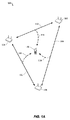
[0030]図1Aを参照すると、クライアント局の位置を決定するための受動測位方式の例示的ブロック図が示されている。受動測位方式は、3つのアクセスポイント102、104、106と、クライアント局120とを備えるワイヤレス通信ネットワーク100を含む。アクセスポイント102、104、106は、それら自体の位置を決定することが可能なアドバンストWLANアクセスポイント(たとえば、自己位置特定アクセスポイント)であってよい。アクセスポイントの各々は、ワイヤレス通信ネットワーク100中の(たとえば、互いの通信範囲内の)1つまたは複数の他のアクセスポイントを選択することができる。いくつかの実装形態において、アクセスポイントは、1つのアクセスポイントがマスタアクセスポイントとして指定され得るとともに、他のアクセスポイントがターゲットアクセスポイントとして指定され得るように配置され得る。クライアント局120は、WLAN通信能力をもつ、どの適切な電子デバイス(たとえば、ノート型コンピュータ、タブレットコンピュータ、ネットブック、モバイルフォン、ゲーム機、携帯情報端末(PDA)、在庫タグなど)であってもよい。さらに、図1Aにおいて、クライアント局120は、1つまたは複数のアクセスポイント102、104、106の通信範囲内にある。
[0030] Referring to FIG. 1A, an exemplary block diagram of a passive positioning scheme for determining the location of a client station is shown. The passive positioning scheme includes a
[0031]ある実施形態では、アクセスポイント102は、他のアクセスポイント104、106のうちの1つまたは複数に、定期的精密タイミングまたはQoSNullメッセージ(M)を送信する。メッセージMは、第1のアクセスポイントに関連付けられた識別子(たとえば、アクセスポイント102のネットワークアドレス)と、第2のアクセスポイントに関連付けられた識別子(たとえば、アクセスポイント104のネットワークアドレス)と、精密タイミングまたはQoSNullメッセージを識別するシーケンス番号と、メッセージMが送信された瞬間を示すタイムスタンプとを備え得る。第2のアクセスポイント104は、メッセージMが送信され、受信された瞬間の間の時間差としてのRTT情報(たとえば、RTT/2)を決定することができる。アクセスポイント102は、1つまたは複数のアクセスポイント104、106から精密タイミングまたはQoSNull肯定応答メッセージ(ACK)を受信し、アクセスポイント104、106の各々に関連したRTTタイミング情報を決定する。メッセージMを受信したことに応答して、第2のアクセスポイント(たとえば、この例ではアクセスポイント104)は、対応する肯定応答ACK応答メッセージを生成し、送信すればよい。一実装形態では、ACKメッセージは、アクセスポイント104におけるメッセージMの受信を示す。ACKメッセージは、第1のアクセスポイント102に関連付けられた識別子と、第2のアクセスポイント104に関連付けられた識別子と、対応する精密タイミングまたはQoSNull要求メッセージを識別するシーケンス番号と、ACKメッセージが送信された瞬間を示すタイムスタンプとを備え得る。
[0031] In some embodiments, the
[0032]第1のアクセスポイント102は、第2のアクセスポイント104からACK応答メッセージを受信し、ACKメッセージが受信された瞬間を決定し、第2のアクセスポイント104に関連したRTTタイミング情報を決定することができる。第1のアクセスポイント102は、第2のアクセスポイント104に関連したRTTタイミング情報を、メッセージMが送信された瞬間と、ACK応答メッセージが受信された瞬間との間の時間差として決定すればよい。図1の例において、第1のアクセスポイント102は、精密タイミングまたはQoSNullメッセージ/ACK応答メッセージ108を第2のアクセスポイント104と交換することができ、精密タイミングまたはQoSNullメッセージ/ACK応答メッセージ110を別のアクセスポイント106と交換することもできる。第2のアクセスポイント104も、精密タイミングまたはQoSNullメッセージ/ACK応答メッセージ112を別のアクセスポイント106と交換することができる。アクセスポイント102、104、106の各々は、ネットワーク中の他のアクセスポイントに関連したRTTタイミング情報を決定することができる。
[0032] The
[0033]クライアント局120は、アクセスポイント102、104、106に関連したTDOAタイミング情報を決定するために、MメッセージとACK応答メッセージとをインターセプトしてよい。破線114、116、118は、クライアント局120が、アクセスポイント102、104、106(たとえば、APクラスタ)の間で交換されるQoSNullメッセージ/ACK応答メッセージ108、110、112をインターセプトすることを表す。クライアント局120は、Mメッセージと、対応するACK応答メッセージとの間の到着時間差を測定することができる。たとえば、クライアント局120は、(第1のアクセスポイント102によって第2のアクセスポイント104に送信された)メッセージMが検出された第1の瞬間を決定することができる。クライアント局120は、(第2のアクセスポイント104によって第1のアクセスポイント102に送信された)ACKメッセージが検出された第2の瞬間を決定することもできる。クライアント局120は、第1および第2のアクセスポイント102、104に関連付けられたTDOAタイミング情報を決定するために、第2の瞬間から第1の瞬間を差し引けばよい。
[0033]
[0034]ある実施形態では、アクセスポイント102、104、106は、RTTタイミング情報およびAP位置情報の指示を備えるRTT測定制御メッセージを送信してよい。一実装形態では、アクセスポイント102、104、106の各々は、近隣アクセスポイントに関連付けられたRTTタイミング情報を示すための、近隣アクセスポイント向けの固有のRTT測定制御メッセージをブロードキャストすることができる。アクセスポイントに関連付けられたRTTタイミング情報に加え、RTT測定制御メッセージは、AP位置情報も備え得る。AP位置情報は、ブロードキャスト元アクセスポイントの位置の指示と、近隣アクセスポイントの位置の指示とを含み得る。クライアント局120は、RTT測定制御メッセージを受信することができ、アクセスポイント102、104、106に関連付けられたAP位置情報と、TDOAタイミング情報と、RTTタイミング情報とを、所定の記憶場所、データ構造、または別の適切な記憶デバイスに記憶することができる。
[0034] In an embodiment, the
[0035]クライアント局120は、少なくとも部分的に、アクセスポイントに関連付けられたAP位置情報、TDOAタイミング情報、およびRTTタイミング情報上での位置を決定するように構成される。いくつかの実装形態では、さらに記載されるように、クライアント局120は、クライアント局120と所定の数のアクセスポイントの各々との間のレンジに関して「測位方程式」を組み立てるのに、AP位置情報と、TDOAタイミング情報と、RTTタイミング情報とを使えばよい。たとえば、3つのターゲットアクセスポイントに関連したAP位置情報、TDOAタイミング情報、およびRTTタイミング情報が利用可能であると決定すると、クライアント局120は、クライアント局120の3次元位置を決定するために、3つの測位方程式を解けばよい。他の実装形態では、クライアント局120は、任意の適切な数のアクセスポイントに関連したAP位置情報、TDOAタイミング情報、およびRTTタイミング情報に基づいて位置を決定し得ることに留意されたい。たとえば、位置は、クライアント局120の2次元位置を決定するために、2つのターゲットアクセスポイントに関連したAP位置情報、TDOAタイミング情報、およびRTTタイミング情報からの2つの独立した測位方程式に基づき得る。
[0035] The
[0036]ある実施形態では、アクセスポイント102、104、106は、クライアント局120にRTT測定情報を送信しない。RTTタイミング情報は、APにおけるSIFS時間を、2つのAP局の間の距離に比例する量だけ変更/修正するのに使われ得る。クライアント局120は、RTT測定情報の知識なしで、位置を決定するように構成される。つまり、位置算出は、アクセスポイント102、104、106に関連付けられたAP位置情報、TDOAタイミング情報、およびSIFS情報に基づく。AP位置情報およびSIFS情報は、定期的ブロードキャストメッセージに含められ、クライアント局120上の所定の記憶場所、データ構造、または別の適切な記憶デバイスに記憶され得る。
In an embodiment, the
[0037]図1Bを参照すると、位置サーバを含むワイヤレスローカルエリアネットワークの例示的ネットワーク図が示されている。ネットワーク150は、アクセスポイント102、104、106と、位置サーバ152と、通信経路154とを含む。位置サーバ152は、プロセッサとメモリとを含むコンピューティングデバイスであり、コンピュータ実行可能命令を実行するように構成される。たとえば、位置サーバ152は、プロセッサと、非一時的メモリと、ディスクドライブと、ディスプレイと、キーボードと、マウスとを含むコンピュータシステムを備える。プロセッサは好ましくは、インテリジェントデバイス、たとえば、Intel(登録商標)CorporationまたはAMD(登録商標)によって製造されたものなどのパーソナルコンピュータ中央処理ユニット(CPU)、マイクロコントローラ、特定用途向け集積回路(ASIC)などであり得る。メモリは、ランダムアクセスメモリ(RAM)と読取り専用メモリ(ROM)とを含む。ディスクドライブは、ハードディスクドライブ、CD−ROMドライブ、および/またはジップドライブを含み、他の形のドライブを含み得る。ディスプレイは、液晶ディスプレイ(LCD)(たとえば、薄膜トランジスタ(TFT)ディスプレイ)であるが、他の形のディスプレイ、たとえば、陰極線管(CRT)が許容される。キーボードおよびマウスは、データ入力機構をユーザに提供する。位置サーバ152は、本明細書に記載される機能を実施するようにプロセッサを制御するための命令を含むプロセッサ可読、プロセッサ実行可能ソフトウェアコードを(たとえば、メモリに)記憶する。これらの機能は、受動測位方式の実装形態を支援する。ソフトウェアは、ネットワーク接続を介してダウンロードされること、ディスクからアップロードされることなどによって、メモリ上にロードされ得る。さらに、ソフトウェアは直接実行可能でないことがあり、たとえば、実行の前にコンパイルを必要とする。アクセスポイント102、104、106は、通信経路154を介して位置情報を交換するために、位置サーバ152と通信するように構成される。通信経路154は、ワイドエリアネットワーク(WAN)であってよく、インターネットを含み得る。位置サーバ152は、APロケーション情報を記憶するためのデータ構造(たとえば、リレーショナルデータベース、フラットファイル)を含み得る。たとえば、位置サーバ152は、AP位置情報(たとえば、緯度/経度、x/y)と、RTT情報と、SIFS情報と、アクセスポイントに関連付けられた他の情報(たとえば、SSID、MACアドレス、不確実性値、カバレージエリアなど)とを含み得る。アクセスポイント102、104、106は位置サーバ152 106と通信することができ、APロケーション情報と、SIFS情報と、RTT情報とを、クライアント局測位ソリューションにおいて使用するために取り出すことができる。位置サーバ152の構成は例示にすぎず、限定ではない。ある実施形態では、位置サーバ152は、アクセスポイントに直接接続されてよい。2つ以上の位置サーバが使われてよい。位置サーバ152は、追加ネットワーク上の他のアクセスポイントに関連した位置情報を含む1つまたは複数のデータベースを含み得る。ある例では、位置サーバ152は複数のサーバユニットからなる。
[0037] Referring to FIG. 1B, an exemplary network diagram of a wireless local area network including a location server is shown.
[0038]図2を参照すると、精密タイミング測定要求の概念図の従来技術例が示されている。この一般的手法は、受信局と送信局とを含む。受信局は送信局に精密タイミング測定要求を送り、対応する肯定応答メッセージを受信し得る。送信局は次いで、時間t1においてアクションフレームMを送信する。アクションフレームMは受信局によって時間t2において受信され、肯定応答メッセージACKが受信局によって時間t3において送信される。クライアント局は、時間t1においてメッセージの出発時間(ToD)を、および時間t3においてACKのToDを検出することができる。ACKメッセージは、時間t4において送信局によって受信される。送信局は次いで、t1およびt4についての値を含む後続メッセージを準備する。受信局は次いで、RTTを、(t4−t1)−(t3−t2)と推定する。RTT情報は次いで、クライアント局に与えられる。従来技術手法は、t4を決定し、その後でRTT値を計算するのに、複数のラウンドトリップメッセージを必要とする。その結果、多くのクライアント局および対応する数の測定要求をもつ環境において、複数のラウンドトリップメッセージは、アクセスポイントおよびクライアント局にとって利用可能な帯域幅に対して大幅な影響を有し得る。以下で論じるように、受動測位方式の利点は、アクセスポイントの間で送信されるメッセージの数を削減することである。 [0038] Referring to FIG. 2, a prior art example of a conceptual diagram of a precise timing measurement request is shown. This general approach includes a receiving station and a transmitting station. The receiving station may send a fine timing measurement request to the transmitting station and receive a corresponding acknowledgment message. The transmitting station then transmits an action frame M at time t1. The action frame M is received by the receiving station at time t2, and an acknowledgment message ACK is transmitted by the receiving station at time t3. The client station can detect the departure time (ToD) of the message at time t1 and the ACK ToD at time t3. The ACK message is received by the transmitting station at time t4. The transmitting station then prepares a subsequent message that includes values for t1 and t4. The receiving station then estimates the RTT as (t4-t1)-(t3-t2). The RTT information is then provided to the client station. The prior art approach requires multiple round trip messages to determine t4 and then calculate the RTT value. As a result, in an environment with many client stations and a corresponding number of measurement requests, multiple round trip messages can have a significant impact on the bandwidth available to access points and client stations. As discussed below, an advantage of the passive positioning scheme is that it reduces the number of messages transmitted between access points.
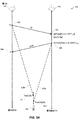
[0039]図1Aをさらに参照しながら図3Aを参照すると、FAC推定値に基づく受動測位方式の概念図の例が示されている。この図は、たとえば、第1のアクセスポイント102と第2のアクセスポイント104との間のQoSNullメッセージ/ACK応答メッセージ108中に含まれるメッセージを含む。この例では、第1のアクセスポイント102(AP1)が送信局であり、第2のアクセスポイント104(AP2)が受信局である。破線118a、118bは、クライアント局120が、それぞれM/ACKメッセージをインターセプトすることを表す。アクセスポイント102、104は、精密タイミングまたはQoSNull交換(たとえば)に定期的に関与する。アクセスポイント102、104は、それらのロケーション情報をブロードキャストし得る。時間t1 302において、AP1から時間メッセージMが出る。メッセージMは、LMのメッセージ長を有する。時間t4 308において、AP2からのACKメッセージがAP1に到着する。AP1からのメッセージMがクライアント局120に届く時間は、クライアントにおける到着時間(すなわち、ToaC(M)310)として示される。AP2からのACKメッセージがクライアント局120に届く時間は、クライアントにおける到着時間(すなわち、ToaC(ACK)312)として示される。位置方程式は、AP1とクライアント局120との間の飛行時間(ToF)、およびAP2とクライアント局120との間のToFに基づき得る。たとえば、光速として「c」を使うと、特異距離は次のように表され得る。
[0039] Referring to FIG. 3A with further reference to FIG. 1A, an example of a conceptual diagram of a passive positioning scheme based on FAC estimates is shown. This diagram includes, for example, messages included in a QoSNull message /
[0040]Diff_dist_12=c*[ToaC(M)−t1−(ToaC(ACK)−t3]
[0041]RTT12/2は、AP1とAP2との間の飛行時間である。RTT12/2についての値は、t1およびt2の時間インスタンスに基づいて決定されてよく、またはAP1およびAP2のロケーションに基づいて確立されてよい。ある実施形態では、AP2は、t2の値(すなわち、MのToA)を、チャネルの初回到着向けに調節するように構成される。図3Bのグラフ350を参照すると、FACの値は受信信号に基づき得る。限定ではなく一例として、FACアルゴリズムは、立上りエッジサンプルと統計的情報とを使うことができる。FACアルゴリズムは、h(n)についての値に対する最大を決定し、次いで、値を「1」に設定すればよい。次いで、可変閾値が適用されてよく、得られたFACが、t2 304を調節するのに使われ得る。
[0040] Diff_dist — 12 = c * [ToaC (M) −t1− (ToaC (ACK) −t3)
[0041] RTT 12/2 is the time of flight between AP1 and AP2. Value for RTT 12/2 may be determined based on the time instances t1 and t2, or may be established based on the location of AP1 and AP2. In some embodiments, AP2 is configured to adjust the value of t2 (ie, M ToA) for the first arrival of the channel. Referring to graph 350 of FIG. 3B, the value of FAC may be based on the received signal. By way of example and not limitation, the FAC algorithm can use rising edge samples and statistical information. The FAC algorithm may determine the maximum for the value for h (n) and then set the value to “1”. A variable threshold may then be applied and the resulting FAC may be used to adjust
[0042]t2=t2+FAC
[0043]t2の値は、FAC値に基づいて調節され得る。AP2は、時間t3 306においてACKメッセージを送るように構成されてよく、ここで、次のようになる。
[0042] t2 = t2 + FAC
[0043] The value of t2 may be adjusted based on the FAC value. AP2 may be configured to send an ACK message at
[0044]t3=t2+SIFS+LM
[0045]SIFSの値は、前のブロードキャストメッセージまたは確立されているネットワーク規格により、既知である。SIFSの具体的な値は、標準値の妥当な範囲内の任意の定数であってよい。メッセージ長LM(すなわち、着信パケットまたはメッセージの長さ)の値は、メッセージMがAP2によって受信されたときに決定され得る。t2に代入を行うと、方程式は、次のように導出され得る。
[0044] t3 = t2 + SIFS + L M
[0045] The value of SIFS is known from previous broadcast messages or established network standards. The specific value of SIFS may be any constant within a reasonable range of standard values. The value of message length L M (ie, incoming packet or message length) may be determined when message M is received by AP2. Substituting for t2, the equation can be derived as follows.
[0046]t2=t1+RTT12/2
[0047]t3=t1+RTT12/2+SIFS+LM
[0048]Diff_dist_12=c*[ToaC(M)−(ToaC(ACK)−(RTT12/2+SIFS+LM))]
[0049]クライアント局120のロケーションを決定するこの方法は、図2に記載される従来技術方法において使われる追加オーバーヘッドパケットを必要としない。クライアント局120は、RTT12データを、前のブロードキャストメッセージの形で、または位置サーバ152からの前のダウンロードにより受信し得る。
[0046] t2 = t1 +
[0047] t3 = t1 +
[0048] Diff_dist_12 = c * [ ToaC (M) - (ToaC (ACK) - (
[0049] This method of determining the location of the
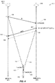
[0050]図3Aをさらに参照しながら図4を参照すると、動的SIFS時間に基づく受動測位方式400の概念図の例が示されている。この例では、アクセスポイントは、精密タイミングまたはQoSNull交換に定期的に関与し、それらのSIFS時間帯域を、交換を行っている相手であるAPまでの距離に比例する量だけ変更する。APは、RTT情報をブロードキャストする必要はなく、クライアント局120上でAP位置情報が利用可能にされている場合、それらのロケーションをブロードキャストする必要はない。ある例では、送信局402(すなわち、AP1)が、時間t1 406においてメッセージMを送信する。受信局404(すなわち、AP2)が、時間t2 408においてメッセージMを受信する。ある実施形態では、時間t2は、前に記載されたように、FACによって調節されてよい。ACKメッセージが、時間t3 410において送信され、時間t4 412において受信される。図3Aに示される実施形態とは対照的に、時点306と308との間の破線として示されているように、時間t3は、AP1とAP2との間の距離に比例する量であるRTT12/2だけ削減される。受信局404(すなわち、AP2)は、時間t3においてACKを送達し、ここで、次の通りである。
[0050] Referring to FIG. 4 with further reference to FIG. 3A, an example conceptual diagram of a
[0051]t3=t2+SIFS−RTT12/2+LM
[0052]図4のt3時点410と、図3Aの(および図4にも示されている)t3時点306との間の差は例示にすぎず、必ずしも比例しない。t3時点410、306は、受信局404が、ACKメッセージを、前述の実施形態よりも早い時間に送るように構成されることを示す。上述したように、QoSNullメッセージMおよびACKメッセージは、クライアント局422によって、414、416においてインターセプトされる。ToaC(M)418は、AP1からのメッセージMがクライアント局422に届く時間であり、ToaC(ACK)420は、AP2からのACKがクライアント局422に届く時間である。特異距離を解くと、次のようになる。
[0051] t3 = t2 + SIFS -
[0052] The difference between the
[0053]Diff_dist_12=c*[ToaC(M)−t1−(ToaC(ACK)−t3]
[0054]t2=t1+RTT12/2
[0055]t3=t1+RTT12/2+SIFS+LM−RTT12/2
[0056]Diff_dist_12=c*[ToaC(M)−(ToaC(ACK)−(SIFS+LM))]
[0057]この手法は、空中の追加パケットのオーバーヘッドも、クライアント局における支援データ(すなわち、RTTデータ)も必要としない。ある実施形態では、クライアント局は、ネットワークベースの測位にのみ依拠する低価格タグ(たとえば、RFIDタグ)である。
[0053] Diff_dist — 12 = c * [ToaC (M) −t1− (ToaC (ACK) −t3)
[0054] t2 = t1 +
[0055] t3 = t1 +
[0056] Diff_dist — 12 = c * [ToaC (M) − (ToaC (ACK) − (SIFS + L M ))]
[0057] This approach does not require any additional packet overhead in the air nor assistance data at the client station (ie, RTT data). In some embodiments, the client station is a low price tag (eg, an RFID tag) that relies only on network-based positioning.
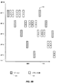
[0058]図5Aを参照すると、例示的アクセスポイントブロードキャストおよびメッセージ交換タイミング図500が示されている。アクセスポイントブロードキャストおよびメッセージ交換タイミング図500は、クラスタ中のアクセスポイント(たとえば、AP1、AP2、AP3、AP4、AP5)のリストをもつy軸502と、時間の進行と、アクセスポイントの各々向けのビーコン送信506用のタイムスロットの指示と、アクセスポイントの各々向けのメッセージ交換508用のタイムスロットの指示とを示すためのx軸504とを含む。メッセージ交換508は、タイムスロットの一般的指示と、交換(たとえば、1−2、2−3、3−4など)に参加しているアクセスポイントの指示とを含む。メッセージ交換は、精密タイミング交換またはQoSNull交換であり得る。ある実施形態では、ビーコン送信は、AP位置情報とRTT情報とを含み得る。クライアント局120が、ビーコン送信506を受動的にリッスンし、次いで、メッセージMと、対応するACKメッセージとを含むメッセージ交換508(たとえば、精密タイミングまたはQoSNullメッセージ)を受信し得る。アクセスポイントブロードキャストおよびメッセージ交換タイミング図500に示すように、AP1は、第1の時間においてビーコンメッセージをブロードキャストし、次いで、第2の時間においてAP2との交換メッセージを開始するように構成され得る。AP2は次いで、ビーコンメッセージをブロードキャストし、次いで、AP3との交換メッセージを開始するように構成され得る。シーケンスは、各APが、クラスタ中の他のアクセスポイントとのメッセージ交換を実行する機会を有するように、図に示すように続き得る。
[0058] Referring to FIG. 5A, an exemplary access point broadcast and message exchange timing diagram 500 is shown. Access point broadcast and message exchange timing diagram 500 shows a y-
[0059]アクセスポイントブロードキャストおよびメッセージ交換タイミング図500におけるタイミングおよび一連のビーコン送信506ならびにメッセージ交換508は例示にすぎず、限定的ではない。たとえば、図5Bを参照すると、タイミング図520は、第1のAPが、ビーコンメッセージをブロードキャストし、次いで、クラスタ中の他のAPのうちの2つ以上とのメッセージ交換を順次開始し得ることを示す。隣接APは次いで、クラスタ中の1つまたは複数のAPとのメッセージ交換を開始することができる。他のシーケンスも使用され得る。ある例では、ビーコン送信506は100msごとに起こってよく、各APは、10個の最も近い隣接APとの精密タイミングまたはQoSNull交換を毎秒(すなわち、完全アップデートを毎秒)実行することができる。5つの隣接APのみがある場合、APは、1秒に2回アップデートするか、または精密タイミング交換を1つのビーコンおきに実行し、毎秒アップデートするように構成され得る。2つの隣接APのみを含む例では、次いで、APは、1秒に5回アップデートするか、5つのビーコンごとに精密タイミング交換を実行し、毎秒アップデートするように構成され得る。他のビーコン送信およびメッセージ交換シナリオが、ネットワーク(たとえば、クラスタ)のサイズ、ネットワークハードウェアおよびソフトウェアの技術的能力、または他のパフォーマンス基準に基づいて使われてよい。
[0059] The timing and series of
[0060]動作時、図1A〜図4をさらに参照しながら図6を参照すると、ワイヤレス通信ネットワーク100を使ってRTT値に基づいて肯定応答を送るためのプロセス600は、図示される段階を含む。ただし、プロセス600は、例にすぎず、限定的なものではない。プロセス600は、たとえば、段階を追加、除去、または並べ替えることによって改変できる。たとえば、段階604において初回到着補正(FAC)を決定することは随意であり、プロセス600に含まれる必要はない。
[0060] In operation, referring to FIG. 6 with further reference to FIGS. 1A-4, a
[0061]段階602において、受信局(たとえば、第2のアクセスポイント104(AP2))が、近隣送信局(たとえば、第1のアクセスポイント102(AP1))からの着信メッセージを検出するように構成される。アクセスポイントは、少なくとも1つのプロセッサとメモリとを含むアドバンストWLANアクセスポイントであってよい。着信メッセージは、精密タイミングメッセージまたはQoSNullメッセージなどのパケット交換であってよく、送信局からメッセージが送信された時間を示すタイムスタンプを含み得る。
[0061] At
[0062]段階604において、受信局は、着信メッセージの到着時間を決定することができる。ある実施形態では、ワイヤレス通信における多チャネル効果の影響により、到着時間は補正される必要があり得る。受信側アクセスポイントは、着信メッセージに対して随意の初回到着補正(FAC)アルゴリズムを実行し、到着時間を決定するように構成され得る。
[0062] In
[0063]段階606において、受信局(たとえば、第2のアクセスポイント104(AP2))は、送信局(たとえば、AP1)に関連付けられたRTT値を決定することができる。ある実施形態では、RTT値は、メッセージが送信された時間(たとえば、タイムスタンプ)に基づいて決定され得る。RTT値(すなわち、情報)は、前の精密タイミングメッセージ交換に基づいて決定され得る。たとえば、受信局は、前のRTT情報をローカルメモリに記憶すればよく、位置サーバ152上のデータベースへのアクセスを有することができる。ある例では、RTT情報は、ビーコン送信506に含められてよく、または送付局および受信局の相対的な位置に基づき得る。段階608において、受信局は、段階602において検出された着信メッセージに応答して、肯定応答メッセージ(ACK)を生成する。
[0063] At
[0064]段階610において、受信局は、着信メッセージに対する肯定応答メッセージについての出発時間を、RTT値に基づいて算出するように構成され得る。たとえば、ワイヤレス通信ネットワーク100は、各参加局(たとえば、102、104、106)についての確立されたSIFS値を有し得る。例示的なSIFS値は16マイクロ秒(またはネットワーキング規格によって設定された他の値)であり得る。受信局は、SIFS値を、送信局までの距離に比例する量だけ削減してよい。たとえば、SIFS値は、RTT値の半分(たとえば、RTT/2)だけ削減され得る。段階612において、図4を参照すると、受信局は、出発時間(たとえば、時間t3 410)において肯定応答メッセージを送るように構成され得る。肯定応答メッセージは、出発時間を示すタイムスタンプを含み得る。
[0064] In
[0065]動作時、図1A〜図5Bをさらに参照しながら図7を参照すると、ワイヤレス通信ネットワーク100を使ってクライアント局422の位置を算出するためのプロセス700は、図示される段階を含む。ただし、プロセス700は、例にすぎず、限定的なものではない。プロセス600は、たとえば、段階を追加、除去、または並べ替えることによって改変できる。たとえば、位置算出が、クライアント局422上のプロセッサ(すなわち、ローカル)によって、または位置サーバ152中のプロセッサ(すなわち、リモート)によって行われてよい。
[0065] In operation, referring to FIG. 7 with further reference to FIGS. 1A-5B, a
[0066]段階702において、クライアント局422は、第2のAP(AP2)とのメッセージ交換を示す、第1のAP(AP1)からのブロードキャストメッセージを検出することができる。ある例では、ブロードキャストメッセージは、AP1から送信されるビーコン送信506であり得る。ブロードキャストメッセージは、後続メッセージ交換の指示を含み得る。ある実施形態では、ブロードキャストメッセージは、RTT情報もAPロケーション情報も含まない。段階704において、クライアント局422は、AP1からAP2に送られる第1のメッセージを検出する(たとえば、414においてインターセプトする)ように構成され得る。たとえば、第1のメッセージは、精密時間要求またはQoSNullメッセージ(たとえば、メッセージM)であってよい。第1のメッセージは、LMで示されるメッセージ長を有することになる。クライアント局422は、第1のメッセージの到着時間の瞬間(たとえば、ToaC(M)418)を決定し、記憶することができる。
[0066] At
[0067]段階706において、クライアント局422は、第2のAP(AP2)から第1のAP(AP1)に送られる後続メッセージを検出する(たとえば、416においてインターセプトする)ように構成され得る。たとえば、クライアント局422は、時間t3 410において受信局404から送信されるACKメッセージを検出し得る。クライアント局422は、ACKメッセージについての到着時間の瞬間(たとえば、ToaC(ACK)420)を決定し、記憶するように構成され得る。ACKメッセージは、送信の時間(たとえば、時間t3 404)を示すタイムスタンプを含み得る。
[0067] At
[0068]段階708において、クライアント局422は、AP1およびAP2に関連したロケーション情報を決定することができる。この情報は、クライアント局422上にあらかじめ記憶されてよい。たとえば、ネットワーク中の局のロケーションは、位置サーバ152からダウンロードされ得る。段階710において、クライアント局422は、ショートフレーム間スペース(SIFS)値を決定する。ある例では、SIFS値は、ネットワーク向けのあらかじめ確立された定数であってよい。ロケーションおよびSIFSデータをクライアント局422に提供するための他の機構は、プッシュ通知、位置ベースのサービスを含んでよく、同期が使われ得る。段階712において、クライアント局422は、段階704においてインターセプトされたメッセージに基づいて、LMの値を決定することができる。クライアント局422は、ToaC(M)およびToaC(ACK)についての時間インスタンスに基づいて位置を計算するように構成され得る。段階714において、クライアント局は、到着時間差(TDOA)情報を、ToaC(M)およびToaC(ACK)についての時間インスタンスとして決定する。
[0068] At
[0069]段階716において、クライアント局422は、第1および第2のAPについてのロケーション情報、TDOAタイミング情報、SIFS値、ならびにメッセージ長値に基づいて、位置推定値を算出するように構成される。ある実施形態では、位置サーバ152、または他のネットワークハードウェア(たとえば、アクセスポイント、ライブラリサーバ)の処理能力が、算出を実施するのに使われ得る。位置推定値は、次のように表される特異距離公式に基づき得る。
[0069] At
[0070]Diff_dist_12=c*[ToaC(M)−(ToaC(ACK)−(SIFS+LM))]
[0071]上式で、「c」は光速であり、SIFSは確立されたシステム定数であり、LMは第1のメッセージのメッセージ長である。クライアント局422は、追加位置推定値を決定し、次いで、得られた位置推定値を、クライアント局422の位置を決定するために組み合わせるために、追加APを用いてプロセス700を繰り返すように構成され得る。
[0070] Diff_dist — 12 = c * [ToaC (M) − (ToaC (ACK) − (SIFS + L M ))]
[0071] In the above equation, "c" is the speed of light, SIFS is a system constant that is established, L M is the message length of the first message. The
[0072]実施形態は、完全にハードウェアの実施形態、完全にソフトウェアの実施形態(ファームウェア、常駐ソフトウェア、マイクロコードなどを含む)、または、本明細書では「回路」、「モジュール」、もしくは「システム」とすべてが全般に呼ばれ得る、ソフトウェアの態様とハードウェアの態様を組み合わせた実施形態という、形式をとり得る。さらに、本発明の主題の実施形態は、媒体で具体化されるコンピュータ使用可能プログラムコードを有する任意の有形の表現媒体で具体化されるコンピュータプログラム製品の形態をとることができる。説明した実施形態は、すべての想到できる変形が本明細書に列挙されているわけではないので、現在記載されているかどうかにかかわらず、実施形態に従ってプロセスを実行する(たとえば、実施する)ために、コンピュータシステム(または他の電子デバイス)をプログラムするために使用され得る命令を記憶する機械可読媒体を含み得る、コンピュータプログラム製品またはソフトウェアとして提供され得る。機械可読媒体は、機械(たとえば、コンピュータ)によって読取り可能な形態(たとえば、ソフトウェア、処理アプリケーション)で情報を記憶または送信するための任意の機構を含む。機械可読媒体は、機械可読記憶媒体、または機械可読信号媒体とすることができる。機械可読記憶媒体は、たとえば、限定はしないが、磁気記憶媒体(たとえば、フロッピー(登録商標)ディスケット)、光学記憶媒体(たとえば、CD−ROM)、光磁気記憶媒体、読取り専用メモリ(ROM)、ランダムアクセスメモリ(RAM)、消去可能プログラマブルメモリ(たとえば、EPROMおよびEEPROM(登録商標))、フラッシュメモリ、または電子命令を記憶することに適した他のタイプの有形の媒体を含み得る。機械可読信号媒体は、コンピュータ可読プログラムコードが組み込まれた伝搬されるデータ信号、たとえば、電気信号、光信号、音響信号、または他の形式の伝搬される信号(たとえば、搬送波、赤外線信号、デジタル信号など)を含み得る。機械可読信号媒体上で実施されるプログラムコードは、ワイヤライン、ワイヤレス、光ファイバケーブル、RF、または他の通信媒体を含むがこれに限定されない任意の適切な媒体を使用して送信され得る。 [0072] An embodiment may be a fully hardware embodiment, a fully software embodiment (including firmware, resident software, microcode, etc.), or "circuitry", "module", or " It may take the form of an embodiment that combines software aspects and hardware aspects, all of which can be generally referred to as a “system”. Furthermore, embodiments of the present inventive subject matter can take the form of a computer program product embodied in any tangible representation medium having computer-usable program code embodied in the medium. The described embodiments are not intended to enumerate all conceivable variations herein, to perform (eg, perform) a process according to embodiments, whether or not currently described. It can be provided as a computer program product or software, which can include machine-readable media storing instructions that can be used to program a computer system (or other electronic device). A machine-readable medium includes any mechanism for storing or transmitting information in a form (eg, software, processing application) readable by a machine (eg, a computer). The machine readable medium may be a machine readable storage medium or a machine readable signal medium. Machine-readable storage media include, but are not limited to, magnetic storage media (eg, floppy diskette), optical storage media (eg, CD-ROM), magneto-optical storage media, read-only memory (ROM), Random access memory (RAM), erasable programmable memory (eg, EPROM and EEPROM®), flash memory, or other types of tangible media suitable for storing electronic instructions may be included. A machine-readable signal medium is a propagated data signal that incorporates computer-readable program code, such as an electrical signal, an optical signal, an acoustic signal, or other form of propagated signal (eg, a carrier wave, an infrared signal, a digital signal). Etc.). Program code implemented on a machine readable signal medium may be transmitted using any suitable medium including, but not limited to, wireline, wireless, fiber optic cable, RF, or other communication medium.
[0073]実施形態の動作を実施するためのコンピュータプログラムコードは、Java(登録商標)、Smalltalk、C++などのオブジェクト指向プログラミング言語、および「C」プログラミング言語または同様のプログラミング言語などの従来の手続き型プログラミング言語を含む、1つまたは複数のプログラミング言語のいずれかの組合せで書かれることが可能である。プログラムコードは、完全にユーザのコンピュータで、一部をユーザのコンピュータで、スタンドアロンソフトウェアパッケージとして、一部をユーザのコンピュータで、および一部をリモートコンピュータで、または完全にリモートコンピュータもしくはサーバで、実行することができる。後者のシナリオでは、リモートコンピュータは、ローカルエリアネットワーク(LAN)、パーソナルエリアネットワーク(PAN)、または、ワイドエリアネットワーク(WAN)を含む任意のタイプのネットワークを通してユーザのコンピュータに接続され得る、または、外部コンピュータへの接続が(たとえば、インターネットサービスプロバイダを使用するインターネット通して)行われ得る。 [0073] Computer program code for performing the operations of the embodiments is conventional procedural, such as an object-oriented programming language such as Java, Smalltalk, C ++, and the "C" programming language or similar programming language. It can be written in any combination of one or more programming languages, including programming languages. Program code runs entirely on the user's computer, partly on the user's computer, as a stand-alone software package, partly on the user's computer, and partly on the remote computer, or completely on the remote computer or server can do. In the latter scenario, the remote computer can be connected to the user's computer through any type of network, including a local area network (LAN), personal area network (PAN), or wide area network (WAN), or externally A connection to a computer can be made (eg, over the internet using an internet service provider).
[0074]図8Aを参照することは、受動測位方式において使用するための電子デバイス800の一実施形態のブロック図である。クライアント局120は電子デバイス800であってよい。いくつかの実装形態において、電子デバイス800は、測位およびワイヤレス通信能力をもつWLANデバイス(たとえば、ホームノードB(HNB))を備えるノート型コンピュータ、タブレットコンピュータ、ネットブック、モバイル電話、ゲーム機、携帯情報端末(PDA)、在庫タグ、または他の電子システムのうちの1つであってよい。電子デバイス800は、プロセッサユニット802(複数のプロセッサ、複数のコア、複数のノードを含む場合、および/またはマルチスレッドを実施する場合などもある)を含む。電子デバイス800は、メモリユニット806を含む。メモリユニット806は、システムメモリ(たとえば、キャッシュ、SRAM、DRAM、ゼロキャパシタRAM、ツイントランジスタRAM、eDRAM、EDO RAM、DDR RAM、EEPROM、NRAM、RRAM(登録商標)、SONOS、PRAM、その他の中の1つもしくは複数)、または、マシン可読媒体のすでに上述された可能な実現例の中のいずれかの1つもしくは複数であり得る。電子デバイス800はまた、バス810(たとえば、PCI、ISA、PCI−Express、HyperTransport(登録商標)、InfiniBand(登録商標)、NuBus、AHB、AXIなど)と、ワイヤレスネットワークインターフェース(たとえば、WLANインターフェース、Bluetooth(登録商標)インターフェース、WiMAXインターフェース、ZigBee(登録商標)インターフェース、ワイヤレスUSBインターフェースなど)およびワイヤードネットワークインターフェース(たとえば、Ethernet(登録商標)インターフェースなど)のうちの少なくとも1つを含むネットワークインターフェース804とを含む。
[0074] Referring to FIG. 8A, a block diagram of one embodiment of an
[0075]電子デバイス800は、通信ユニット808も含む。通信ユニット808は、測位ユニット812と、受信機814と、送信機816と、1つまたは複数のアンテナ818とを備える。送信機816、アンテナ818、および受信機814は、ワイヤレス通信モジュール(トランシーバ820である、送信機816と受信機814とを有する)を形成する。送信機816および受信機814は、1つまたは複数のクライアント局および他のアクセスポイントと、対応するアンテナ818を介して双方向に通信するように構成される。いくつかの実施形態では、電子デバイス800は、測位能力をもつWLANクライアント局として構成され得る。測位ユニット812は、アクセスポイントに関連したTDOAタイミング情報を決定するために、アクセスポイントの間で交換される精密タイミングまたはQoSNull要求/応答メッセージを検出することができる。測位ユニット812は、図1〜図7を参照して上述したように、TDOAタイミング情報、およびAP位置情報に少なくとも部分的に基づいて、電子デバイス800の位置を決定することができる。いくつかの実施形態では、アクセスポイント102、104、106は、図8Aの電子デバイス800として構成されてもよい。本実施形態では、アクセスポイントは、それらの処理能力を、上述したそれらのそれぞれの動作を実行するのに使うことができる。これらの機能性のうちの任意のものは、ハードウェア内および/またはプロセッサユニット802上に、部分的に(または、全体的に)実装され得る。たとえば、その機能性は、特定用途向け集積回路によって、プロセッサユニット802において実施されたロジックにおいて、周辺デバイスもしくはカード上のコプロセッサにおいて、またはその他において実装され得る。さらに、実現形態は、より少数の構成要素、または図8Aに示されない追加の構成要素(たとえば、ビデオカード、オーディオカード、追加のネットワークインターフェース、周辺デバイスなど)を含み得る。プロセッサユニット802、メモリユニット806、およびネットワークインターフェース804は、バス810に結合されている。バス810に結合されているものとして示されているが、メモリユニット806は、プロセッサユニット802に結合され得る。
[0075] The
[0076]図8Bを参照すると、アクセスポイント(AP)850の例は、プロセッサ851と、ソフトウェア854を含むメモリ852と、送信機856と、アンテナ858と、受信機860とを含むコンピュータシステムを備える。いくつかの実施形態では、アクセスポイント102、104、106は、図8BのAP850として構成されてもよい。送信機856、アンテナ858、および受信機860は、ワイヤレス通信モジュール(トランシーバである、送信機856と受信機860とを有する)を形成する。送信機856はアンテナ858のうちの1つに接続されており、受信機860はアンテナ858のうちの別の1つに接続されている。他の例示的なAPは、たとえば、1つだけのアンテナ858を有する、ならびに/あるいは複数の送信機856および/または複数の受信機860を有する、異なる構成を有してよい。送信機856および受信機860は、AP850が、アンテナ858を介してクライアント局120と双方向に通信できるように構成されている。プロセッサ851は、好ましくは、インテリジェントハードウェアデバイス、たとえば、ARM(登録商標)、Intel(登録商標)Corporation、またはAMD(登録商標)製のものなどの中央処理ユニット(CPU)、マイクロコントローラ、特定用途向け集積回路(ASIC)などである。プロセッサ851は、AP850内に分散され得る複数の別々の物理エンティティを備え得る。メモリ852は、ランダムアクセスメモリ(RAM)と読取り専用メモリ(ROM)とを含む。メモリ852は、プロセッサ可読であるソフトウェア854と、実行されると、プロセッサ851に、本明細書に記載の様々な機能(説明は、機能を実行するプロセッサ851のみを参照する場合があるが)を実施させるように構成されたプロセッサ可読命令を含むプロセッサ実行可能ソフトウェアコードとを記憶するプロセッサ可読記憶媒体である。代替的に、ソフトウェア854は、プロセッサ851によって直接実行可能でなくてもよいが、たとえばコンパイルおよび実行されると、プロセッサ851に機能を実施させるように構成される。
[0076] Referring to FIG. 8B, an example access point (AP) 850 includes a computer system that includes a
[0077]様々な実装形態および活用を参照して実施形態が説明されたが、これらの実施形態は例示であり、本発明の主題の範囲はそれらに限定されないということが理解されよう。概して、本明細書に記載されるワイヤレス通信デバイス用の受動測位方式のための技法は、どの1つのハードウェアシステムまたは複数のハードウェアシステムとも矛盾しない機構を有して実装され得る。多くの変形、修正、追加、改善が可能である。 [0077] While embodiments have been described with reference to various implementations and uses, it will be understood that these embodiments are illustrative and that the scope of the present subject matter is not so limited. In general, the techniques for passive positioning schemes for wireless communication devices described herein may be implemented with mechanisms consistent with any one hardware system or multiple hardware systems. Many variations, modifications, additions and improvements are possible.
[0078]複数の事例は、本明細書に記載される構成要素、動作または構造に、単一の事例としてもたらされ得る。最後に、様々な構成要素、動作、データストアの間の境界は、ある程度任意であり、特定の動作が特有の例示的な構成に照らして示される。機能性の他の割振りは、予見され、本発明の主題の範囲内に属し得る。一般に、例示的な構成で別個の構成要素として示される構造および機能性は、組み合わせられた構造または構成要素として実施され得る。同様に、単一の構成要素として示される構造および機能性は、別個の構成要素として実施され得る。これらおよび他の変形、修正、追加、および改善は、本発明の主題の範囲内に属し得る。 [0078] Multiple instances may result in a single instance for a component, operation or structure described herein. Finally, the boundaries between the various components, operations, data stores are somewhat arbitrary and specific operations are shown in the context of a specific exemplary configuration. Other allocations of functionality are foreseen and may fall within the scope of the present subject matter. In general, structures and functionality shown as separate components in the exemplary configurations may be implemented as a combined structure or component. Similarly, structure and functionality shown as a single component may be implemented as separate components. These and other variations, modifications, additions and improvements may fall within the scope of the present subject matter.
[0079]特許請求の範囲を含めて、本明細書で使用される場合、別段に明記されていない限り、機能または動作が項目または状態「に基づく」という文は、その機能または動作が、述べられた項目または状態に基づき、述べられた項目または状態に加えて1つまたは複数の項目および/または状態に基づき得ることを意味する。 [0079] As used herein, including the claims, unless stated otherwise, the statement that a function or operation is "based on" an item or state refers to that function or operation. Based on the stated item or condition, this means that it may be based on one or more items and / or conditions in addition to the stated item or condition.
[0080]さらに、複数の発明が開示され得る。
以下に、本願出願の当初の特許請求の範囲に記載された発明を付記する。
[C1]
アクセスポイントの間で測位メッセージを交換するための方法であって、
アクセスポイントからの着信メッセージを検出することと、
前記アクセスポイントに関連付けられたラウンドトリップ時間(RTT)値を決定することと、
肯定応答メッセージを生成することと、
前記RTT値に少なくとも部分的に基づいて、前記肯定応答メッセージについての出発時間を算出することと、
前記出発時間に前記肯定応答メッセージを送ることとを含む、方法。
[C2]
前記着信メッセージのための初回到着補正(FAC)を計算することをさらに備える、C1に記載の方法。
[C3]
前記肯定応答メッセージについての前記出発時間は前記FACに少なくとも部分的に基づく、C2に記載の方法。
[C4]
ショートフレーム間スペース(SIFS)値を決定することをさらに備え、前記出発時間を算出することは、前記RTT値および前記SIFS値に基づく、C1に記載の方法。
[C5]
前記肯定応答メッセージについての前記出発時間を算出することは、
t3=t2+SIFS−RTT/2+L M に従って実施され、
ここにおいて、
t3は前記出発時間であり、
t2は、前記着信メッセージが検出された時間であり、
SIFSは、前記アクセスポイントに関連付けられた前記ショートフレーム間スペースであり、
RTT/2は、前記着信メッセージが送られた時間インスタンスと前記着信メッセージが検出された時間インスタンスとの間の時間差であり、
L M は前記着信メッセージの長さである、C4に記載の方法。
[C6]
前記着信メッセージのメッセージ長を決定することをさらに備える、C1に記載の方法。
[C7]
前記着信メッセージはQoSNullメッセージである、C1に記載の方法。
[C8]
アクセスポイント間メッセージ通信を使用する、クライアント局における測位の方法であって、
クライアント局において、第2のアクセスポイントとのメッセージ交換を示す、第1のアクセスポイントからのブロードキャストメッセージを検出することと、
第1のメッセージを検出することと、ここにおいて、前記第1のメッセージは、前記第1のアクセスポイントから前記第2のアクセスポイントに送られる、
第2のメッセージを検出することと、ここにおいて、前記第2のメッセージは、前記第2のアクセスポイントから前記第1のアクセスポイントに送られる、
前記第1のアクセスポイントおよび前記第2のアクセスポイントに関連付けられたロケーション情報を決定することと、
ショートフレーム間スペース(SIFS)値を決定することと、
前記第1のメッセージについてのメッセージ長値を決定することと、
前記第1のメッセージおよび前記第2のメッセージの前記検出に少なくとも部分的に基づいて、到着時間差(TDOA)情報を決定することと、
前記第1のアクセスポイントおよび前記第2のアクセスポイントに関連付けられた前記ロケーション情報、前記TDOA情報、前記SIFS値、ならびに前記メッセージ長値に基づいて、位置推定値を算出することとを備える、方法。
[C9]
前記第1のメッセージは精密タイミングメッセージである、C8に記載の方法。
[C10]
前記第1のメッセージはQoSNullメッセージである、C8に記載の方法。
[C11]
前記ブロードキャストメッセージは、前記第1のアクセスポイントおよび前記第2のアクセスポイントに関連付けられた前記ロケーション情報を含む、C8に記載の方法。
[C12]
前記ブロードキャストメッセージは、前記第1のアクセスポイントおよび前記第2のアクセスポイントに関連付けられたラウンドトリップ時間(RTT)情報を含む、C8に記載の方法。
[C13]
前記ブロードキャストメッセージは前記SIFS値を含む、C8に記載の方法。
[C14]
モバイルユニットの受動測位において使用するための、メッセージを交換するためのシステムであって、
メモリユニットと、
前記メモリユニットに結合されるとともに、
アクセスポイントからの着信メッセージを検出し、
前記アクセスポイントに関連付けられたラウンドトリップ時間(RTT)値を決定し、
肯定応答メッセージを生成し、
前記RTT値に基づいて、前記肯定応答メッセージについての出発時間を算出し、
前記出発時間に前記肯定応答メッセージを送るように構成された少なくとも1つのプロセッサとを備える、システム。
[C15]
前記少なくとも1つのプロセッサは、前記着信メッセージのための初回到着補正(FAC)を計算するようにさらに構成される、C14に記載のシステム。
[C16]
前記少なくとも1つのプロセッサは、前記FACに少なくとも部分的に基づいて、前記肯定応答メッセージについての前記出発時間を算出するようにさらに構成される、C14に記載のシステム。
[C17]
前記少なくとも1つのプロセッサは、ショートフレーム間スペース(SIFS)値を決定し、前記RTT値および前記SIFS値に基づいて前記出発時間を算出するようにさらに構成される、C14に記載のシステム。
[C18]
前記少なくとも1つのプロセッサは、前記肯定応答メッセージについての前記出発時間を、
t3=t2+SIFS−RTT/2+L M に従って算出するようにさらに構成され、
ここにおいて、
t3は前記出発時間であり、
t2は、前記着信メッセージが検出された時間であり、
SIFSは、前記アクセスポイントに関連付けられた前記ショートフレーム間スペースであり、
RTT/2は、前記着信メッセージが送られた時間インスタンスと前記着信メッセージが検出された時間インスタンスとの間の時間差であり、
L M は前記着信メッセージの長さである、C17に記載のシステム。
[C19]
前記少なくとも1つのプロセッサは、前記着信メッセージのメッセージ長を決定するようにさらに構成される、C14に記載のシステム。
[C20]
前記少なくとも1つのプロセッサは、QoSNullメッセージを、前記アクセスポイントからの前記着信メッセージとして検出するようにさらに構成される、C14に記載のシステム。
[C21]
プロセッサと、
前記プロセッサに結合されるとともに、
第2のアクセスポイントとのメッセージ交換を示す、第1のアクセスポイントからのブロードキャストメッセージを検出し、
第1のメッセージを検出し、ここにおいて、前記第1のメッセージは、前記第1のアクセスポイントから前記第2のアクセスポイントに送られる、
第2のメッセージを検出し、ここにおいて、前記第2のメッセージは、前記第2のアクセスポイントから前記第1のアクセスポイントに送られる、
前記第1のアクセスポイントおよび前記第2のアクセスポイントに関連付けられたロケーション情報を決定し、
ショートフレーム間スペース(SIFS)値を決定し、
前記第1のメッセージについてのメッセージ長値を決定し、
前記第1のメッセージおよび前記第2のメッセージの前記検出に少なくとも部分的に基づいて、到着時間差(TDOA)情報を決定し、
前記第1のアクセスポイントおよび前記第2のアクセスポイントに関連付けられた前記ロケーション情報、前記TDOA情報、前記SIFS値、ならびに前記メッセージ長値に基づいて、位置推定値を算出するように構成された測位ユニットとを備える、クライアント局。
[C22]
前記測位ユニットは、前記第1のメッセージとして精密タイミングメッセージを検出するようにさらに構成される、C21に記載のクライアント局。
[C23]
前記測位ユニットは、前記第1のメッセージとしてQoSNullメッセージを検出するようにさらに構成される、C21に記載のクライアント局。
[C24]
前記測位ユニットは、前記ブロードキャストメッセージ中の、前記第1のアクセスポイントおよび前記第2のアクセスポイントに関連付けられた前記ロケーション情報を検出するようにさらに構成される、C21に記載のクライアント局。
[C25]
前記測位ユニットは、前記ブロードキャストメッセージ中の、前記第1のアクセスポイントおよび前記第2のアクセスポイントに関連付けられたラウンドトリップ時間(RTT)情報を検出するようにさらに構成される、C21に記載のクライアント局。
[C26]
前記測位ユニットは、前記ブロードキャストメッセージ中の前記SIFS値を検出するようにさらに構成される、C21に記載のクライアント局。
[0080] Further, a plurality of inventions may be disclosed.
Hereinafter, the invention described in the scope of claims of the present application will be appended.
[C1]
A method for exchanging positioning messages between access points,
Detecting incoming messages from the access point;
Determining a round trip time (RTT) value associated with the access point;
Generating an acknowledgment message;
Calculating a departure time for the acknowledgment message based at least in part on the RTT value;
Sending the acknowledgment message at the departure time.
[C2]
The method of C1, further comprising calculating a first arrival correction (FAC) for the incoming message.
[C3]
The method of C2, wherein the departure time for the acknowledgment message is based at least in part on the FAC.
[C4]
The method of C1, further comprising determining a short inter-frame space (SIFS) value, wherein calculating the departure time is based on the RTT value and the SIFS value.
[C5]
Calculating the departure time for the acknowledgment message is:
is carried out according to t3 = t2 + SIFS-RTT / 2 + L M,
put it here,
t3 is the departure time,
t2 is the time when the incoming message is detected;
SIFS is the short interframe space associated with the access point;
RTT / 2 is the time difference between the time instance when the incoming message was sent and the time instance when the incoming message was detected;
L M is the length of the incoming message, the method described in C4.
[C6]
The method of C1, further comprising determining a message length of the incoming message.
[C7]
The method of C1, wherein the incoming message is a QoSNull message.
[C8]
A method of positioning in a client station using message communication between access points,
Detecting at the client station a broadcast message from the first access point indicating a message exchange with the second access point;
Detecting a first message, wherein the first message is sent from the first access point to the second access point;
Detecting a second message, wherein the second message is sent from the second access point to the first access point;
Determining location information associated with the first access point and the second access point;
Determining a short inter-frame space (SIFS) value;
Determining a message length value for the first message;
Determining time of arrival difference (TDOA) information based at least in part on the detection of the first message and the second message;
Calculating a position estimate based on the location information associated with the first access point and the second access point, the TDOA information, the SIFS value, and the message length value. .
[C9]
The method of C8, wherein the first message is a fine timing message.
[C10]
The method of C8, wherein the first message is a QoSNull message.
[C11]
The method of C8, wherein the broadcast message includes the location information associated with the first access point and the second access point.
[C12]
The method of C8, wherein the broadcast message includes round trip time (RTT) information associated with the first access point and the second access point.
[C13]
The method of C8, wherein the broadcast message includes the SIFS value.
[C14]
A system for exchanging messages for use in passive positioning of a mobile unit,
A memory unit;
Coupled to the memory unit;
Detect incoming messages from access points,
Determining a round trip time (RTT) value associated with the access point;
Generate an acknowledgment message,
Calculating a departure time for the acknowledgment message based on the RTT value;
And at least one processor configured to send the acknowledgment message at the departure time.
[C15]
The system of C14, wherein the at least one processor is further configured to calculate a first arrival correction (FAC) for the incoming message.
[C16]
The system of C14, wherein the at least one processor is further configured to calculate the departure time for the acknowledgment message based at least in part on the FAC.
[C17]
The system of C14, wherein the at least one processor is further configured to determine a short inter-frame space (SIFS) value and calculate the departure time based on the RTT value and the SIFS value.
[C18]
The at least one processor determines the departure time for the acknowledgment message,
further configured to calculate in accordance with t3 = t2 + SIFS-RTT / 2 + L M,
put it here,
t3 is the departure time,
t2 is the time when the incoming message is detected;
SIFS is the short interframe space associated with the access point;
RTT / 2 is the time difference between the time instance when the incoming message was sent and the time instance when the incoming message was detected;
The system according to C17, wherein L M is the length of the incoming message.
[C19]
The system of C14, wherein the at least one processor is further configured to determine a message length of the incoming message.
[C20]
The system of C14, wherein the at least one processor is further configured to detect a QoSNull message as the incoming message from the access point.
[C21]
A processor;
Coupled to the processor;
Detecting a broadcast message from the first access point indicating a message exchange with the second access point;
Detecting a first message, wherein the first message is sent from the first access point to the second access point;
Detecting a second message, wherein the second message is sent from the second access point to the first access point;
Determining location information associated with the first access point and the second access point;
Determine the short interframe space (SIFS) value,
Determining a message length value for the first message;
Determining time of arrival difference (TDOA) information based at least in part on the detection of the first message and the second message;
Positioning configured to calculate a position estimate based on the location information, the TDOA information, the SIFS value, and the message length value associated with the first access point and the second access point A client station comprising a unit.
[C22]
The client station of C21, wherein the positioning unit is further configured to detect a fine timing message as the first message.
[C23]
The client station of C21, wherein the positioning unit is further configured to detect a QoSNull message as the first message.
[C24]
The client station of C21, wherein the positioning unit is further configured to detect the location information associated with the first access point and the second access point in the broadcast message.
[C25]
The client of C21, wherein the positioning unit is further configured to detect round trip time (RTT) information associated with the first access point and the second access point in the broadcast message. Bureau.
[C26]
The client station of C21, wherein the positioning unit is further configured to detect the SIFS value in the broadcast message.
Claims (13)
アクセスポイントからの着信メッセージを検出することと、
前記アクセスポイントに関連付けられたラウンドトリップ時間/2(RTT/2)値を決定することと、ここにおいて、前記RTT/2値が、前記着信メッセージが送られた時間インスタンスと前記着信メッセージが検出された時間インスタンスとの間の時間差である、
肯定応答メッセージを生成することと、
t3=t2+SIFS−RTT/2+L M に従って、出発時間t3を算出することと、ここにおいて、t2は、前記着信メッセージが検出された時間であり、SIFSは、前記アクセスポイントに関連付けられたショートフレーム間スペースであり、L M は前記着信メッセージの長さである、
前記出発時間に前記肯定応答メッセージを送ることとを含む、方法。 A method for exchanging positioning messages between access points,
Detecting incoming messages from the access point;
Determining a round trip time / 2 (RTT / 2) value associated with the access point, wherein the RTT / 2 value is detected when the incoming message is sent and the incoming message is detected. The time difference between the time instance
Generating an acknowledgment message;
according t3 = t2 + SIFS-RTT / 2 + L M, and calculating a starting time t3, wherein, t2 is the time the incoming message is detected, SIFS is the short inter-frame space associated with the access point And L M is the length of the incoming message,
Sending the acknowledgment message at the departure time.
メモリユニットと、
前記メモリユニットに結合されるとともに、
アクセスポイントからの着信メッセージを検出し、
前記アクセスポイントに関連付けられたラウンドトリップ時間/2(RTT/2)値を決定し、ここにおいて、前記RTT/2値が、前記着信メッセージが送られた時間インスタンスと前記着信メッセージが検出された時間インスタンスとの間の時間差である、
肯定応答メッセージを生成し、
t3=t2+SIFS−RTT/2+L M に従って、出発時間t3を算出し、ここにおいて、t2は、前記着信メッセージが検出された時間であり、SIFSは、前記アクセスポイントに関連付けられたショートフレーム間スペースであり、L M は前記着信メッセージの長さである、
前記出発時間に前記肯定応答メッセージを送るように構成された少なくとも1つのプロセッサとを備える、システム。 A system for exchanging messages for use in passive positioning of a mobile unit,
A memory unit;
Coupled to the memory unit;
Detect incoming messages from access points,
Determining a round trip time / 2 (RTT / 2) value associated with the access point, wherein the RTT / 2 value is a time instance when the incoming message was sent and a time when the incoming message was detected; The time difference from the instance,
Generate an acknowledgment message,
according t3 = t2 + SIFS-RTT / 2 + L M, and calculates the departure time t3, wherein, t2 is the time the incoming message is detected, SIFS is located a short interframe space associated with the access point , L M is the length of the incoming message,
And at least one processor configured to send the acknowledgment message at the departure time.
Applications Claiming Priority (11)
| Application Number | Priority Date | Filing Date | Title |
|---|---|---|---|
| US201361872087P | 2013-08-30 | 2013-08-30 | |
| US61/872,087 | 2013-08-30 | ||
| US201361873253P | 2013-09-03 | 2013-09-03 | |
| US61/873,253 | 2013-09-03 | ||
| US201461973034P | 2014-03-31 | 2014-03-31 | |
| US61/973,034 | 2014-03-31 | ||
| US201461985247P | 2014-04-28 | 2014-04-28 | |
| US61/985,247 | 2014-04-28 | ||
| US14/268,978 US9445227B2 (en) | 2013-08-30 | 2014-05-02 | Passive positioning utilizing round trip time information |
| US14/268,978 | 2014-05-02 | ||
| PCT/US2014/050309 WO2015031029A1 (en) | 2013-08-30 | 2014-08-08 | Passive positioning utilizing round trip time information |
Publications (3)
| Publication Number | Publication Date |
|---|---|
| JP2016536600A JP2016536600A (en) | 2016-11-24 |
| JP2016536600A5 JP2016536600A5 (en) | 2017-08-24 |
| JP6363199B2 true JP6363199B2 (en) | 2018-07-25 |
Family
ID=52583131
Family Applications (1)
| Application Number | Title | Priority Date | Filing Date |
|---|---|---|---|
| JP2016538944A Expired - Fee Related JP6363199B2 (en) | 2013-08-30 | 2014-08-08 | Passive positioning using round-trip time information |
Country Status (6)
| Country | Link |
|---|---|
| US (1) | US9445227B2 (en) |
| EP (1) | EP3039445B1 (en) |
| JP (1) | JP6363199B2 (en) |
| KR (1) | KR20160048130A (en) |
| CN (1) | CN105492922B (en) |
| WO (1) | WO2015031029A1 (en) |
Families Citing this family (39)
| Publication number | Priority date | Publication date | Assignee | Title |
|---|---|---|---|---|
| CN101873601A (en) | 2009-04-27 | 2010-10-27 | 松下电器产业株式会社 | Method and system for setting reference signal in wireless communication system |
| US10039073B2 (en) | 2013-01-03 | 2018-07-31 | Qualcomm Incorporated | Method for determining location of wireless devices |
| US9661603B2 (en) | 2013-08-30 | 2017-05-23 | Qualcomm Incorporated | Passive positioning utilizing beacon neighbor reports |
| EP3047296A4 (en) * | 2013-09-18 | 2017-05-17 | Intel Corporation | Fine-timing measurement for time-of-flight positioning |
| US20150264530A1 (en) * | 2014-03-12 | 2015-09-17 | Gaby Prechner | Access point initiated time-of-flight positioning |
| US10225338B1 (en) | 2014-04-15 | 2019-03-05 | Marvell International Ltd. | Peer to peer ranging exchange |
| US9277369B2 (en) * | 2014-06-30 | 2016-03-01 | Qualcomm Technologies International, Ltd. | Method for determining location of wireless devices |
| US9288625B2 (en) * | 2014-06-30 | 2016-03-15 | Qualcomm Technologies International, Ltd. | Method for determining location of wireless devices based on information within messages received from other network devices |
| US10182413B2 (en) | 2014-07-30 | 2019-01-15 | Qualcomm Incorporated | Wireless positioning using scheduled transmissions |
| US10082557B1 (en) * | 2015-02-11 | 2018-09-25 | Marvell International Ltd. | Methods and apparatus for frame filtering in snoop-based range measurements |
| US9763045B2 (en) * | 2015-05-11 | 2017-09-12 | Qualcomm Incorporated | Base station selection for positioning/localization based on an indication of capacity |
| US10009430B2 (en) * | 2015-08-27 | 2018-06-26 | Intel IP Corporation | Apparatus, system and method of fine timing measurement (FTM) |
| US9723631B2 (en) * | 2015-10-26 | 2017-08-01 | Microsoft Technology Licensing, Llc | Bulk fine timing measurement allocation message |
| US9989619B2 (en) | 2015-10-26 | 2018-06-05 | Microsoft Technology Licensing, Llc | Bulk propagation timing measurement messaging |
| US9955499B2 (en) | 2015-10-26 | 2018-04-24 | Microsoft Technology Licensing, Llc | Bulk fine timing measurement message scheduling |
| US20170118587A1 (en) * | 2015-10-26 | 2017-04-27 | Microsoft Technology Licensing, Llc | Location detection using bulk fine timing |
| US10200964B2 (en) * | 2015-11-02 | 2019-02-05 | Intel IP Corporation | Apparatus, system and method of fine timing measurement (FTM) |
| KR101663656B1 (en) * | 2015-11-20 | 2016-10-14 | 한림대학교 산학협력단 | Clustering Period Adaptation SYSTEM AND METHOD for Vehicle-to-Vehicle Communications |
| CN105548962B (en) * | 2015-12-21 | 2018-05-22 | 李奇 | Wireless distance finding localization method and system under asynchronous base station system |
| US9929928B1 (en) * | 2015-12-24 | 2018-03-27 | Microsemi Solutions (U.S.), Inc. | Packet transmitter and method for timestamping packets |
| US9794906B1 (en) | 2016-03-29 | 2017-10-17 | Qualcomm Incorporated | Double sided round trip time calibration |
| US10757675B2 (en) | 2016-06-03 | 2020-08-25 | Locix, Inc. | Systems and methods for precise radio frequency localization in the presence of multiple communication paths |
| US10470156B2 (en) | 2016-06-03 | 2019-11-05 | Locix, Inc. | Systems and methods for coarse and fine time of flight estimates for precise radio frequency localization in the presence of multiple communication paths |
| US10455350B2 (en) | 2016-07-10 | 2019-10-22 | ZaiNar, Inc. | Method and system for radiolocation asset tracking via a mesh network |
| DE102016213689B4 (en) * | 2016-07-26 | 2024-02-29 | Volkswagen Aktiengesellschaft | Device, method and computer program for characterizing antenna units in a predefined space |
| EP3491866B1 (en) * | 2016-08-01 | 2020-10-07 | Telefonaktiebolaget LM Ericsson (PUBL) | Communication nodes and methods therein for positioning in a wireless communications network |
| CN107765213B (en) | 2016-08-15 | 2020-08-25 | 华为技术有限公司 | Positioning method and device |
| US9907047B1 (en) * | 2016-08-30 | 2018-02-27 | Qualcomm Incorporated | Passive positioning procedure and use of single burst ASAP FTM sessions |
| US10650621B1 (en) | 2016-09-13 | 2020-05-12 | Iocurrents, Inc. | Interfacing with a vehicular controller area network |
| US11061103B1 (en) * | 2017-02-10 | 2021-07-13 | Iseeloc, Inc. | Navigation system, device and method using unsynchronized nodes |
| CN109309937B (en) * | 2017-07-26 | 2020-07-07 | 华为技术有限公司 | Method for switching access point, controller, network equipment and storage medium |
| US10568064B2 (en) | 2017-08-23 | 2020-02-18 | Locix, Inc. | Systems and methods for precise radio frequency localization using time difference of arrival |
| US10605889B2 (en) | 2017-08-23 | 2020-03-31 | Locix, Inc. | Systems and methods for precise radio frequency localization using time sweep time difference of arrival |
| CN110622024A (en) * | 2018-03-02 | 2019-12-27 | 深圳市汇顶科技股份有限公司 | Indoor positioning method, device and equipment |
| ES2858366T3 (en) | 2018-04-11 | 2021-09-30 | Teknologian Tutkimuskeskus Vtt Oy | Wireless positioning |
| US10939401B2 (en) * | 2018-07-09 | 2021-03-02 | Qualcomm Incorporated | Round trip time estimation based on a timing advance applied to a timing response |
| US11096141B2 (en) * | 2018-08-27 | 2021-08-17 | Zte Corporation | Location information determination based on timing measurements in wireless networks |
| US11327147B2 (en) | 2018-12-26 | 2022-05-10 | Locix, Inc. | Systems and methods for determining locations of wireless sensor nodes based on anchorless nodes and known environment information |
| US11490354B2 (en) * | 2019-01-11 | 2022-11-01 | Qualcomm Incorporated | Round-trip-time (RTT)-based positioning with listening nodes |
Family Cites Families (38)
| Publication number | Priority date | Publication date | Assignee | Title |
|---|---|---|---|---|
| US6061337A (en) | 1996-12-02 | 2000-05-09 | Lucent Technologies Inc. | System and method for CDMA handoff using telemetry to determine the need for handoff and to select the destination cell site |
| US7450604B2 (en) | 2002-04-20 | 2008-11-11 | Conexant Systems, Inc. | Method and apparatus for establishing circuit connections over local area networks with frequency selective impairments |
| US7188026B2 (en) | 2003-05-12 | 2007-03-06 | Dash Navigation, Inc. | Hierarchical floating car data network |
| EP1721186A1 (en) | 2004-02-17 | 2006-11-15 | Jadi, Inc. | Ultra wide band navigation system with mobile base stations |
| US7224970B2 (en) | 2004-10-26 | 2007-05-29 | Motorola, Inc. | Method of scanning for beacon transmissions in a WLAN |
| US20060133281A1 (en) * | 2004-12-20 | 2006-06-22 | Motorola, Inc. | System for managing round trip time of a transmission control protocol and supporting method and apparatus |
| US7787401B2 (en) | 2005-06-17 | 2010-08-31 | Cisco Technology, Inc. | Using mini-beacons in a wireless network |
| US20070268856A1 (en) | 2006-05-16 | 2007-11-22 | Nokia Corporation | Beacon broadcaster methods and systems for wireless networks |
| EP2079192A4 (en) | 2006-10-30 | 2013-07-31 | Panasonic Corp | Wireless lan communication device and beacon transmitting method |
| WO2008124316A1 (en) * | 2007-04-05 | 2008-10-16 | Skyhook Wireless, Inc. | Time difference of arrival based estimation of speed and direction of travel in a wlan positioning system |
| US8265652B2 (en) | 2007-10-02 | 2012-09-11 | Ricoh Co., Ltd. | Geographic tagging of network access points |
| US20100135178A1 (en) * | 2008-11-21 | 2010-06-03 | Qualcomm Incorporated | Wireless position determination using adjusted round trip time measurements |
| US9125153B2 (en) | 2008-11-25 | 2015-09-01 | Qualcomm Incorporated | Method and apparatus for two-way ranging |
| US9392621B2 (en) * | 2009-06-26 | 2016-07-12 | Qualcomm Incorporated | Initiating a random access procedure for determining communication parameters |
| US9055395B2 (en) * | 2009-11-12 | 2015-06-09 | Cisco Technology, Inc. | Location tracking using response messages identifying a tracked device in a wireless network |
| US20110117924A1 (en) * | 2009-11-18 | 2011-05-19 | Qualcomm Incorporated | Position determination using a wireless signal |
| US8942717B2 (en) | 2009-11-30 | 2015-01-27 | Intel Corporation | Load balancing techniques in wireless networks |
| US8948063B2 (en) * | 2010-01-14 | 2015-02-03 | Qualcomm Incorporated | Method and system for real-time calibration and reporting of processing delay |
| WO2011108480A1 (en) * | 2010-03-03 | 2011-09-09 | 日本電気株式会社 | Packet retransmission control system, packet retransmission control method, and program |
| CN102884440B (en) * | 2010-03-17 | 2016-04-13 | 霍尼韦尔国际公司 | For Short baseline, the system and method determining airborne aircraft position at low cost |
| US8929918B2 (en) | 2010-04-07 | 2015-01-06 | Telefonaktiebolaget L M Ericsson (Publ) | Positioning and location services using civic address information |
| EP2580605B1 (en) | 2010-06-11 | 2016-05-04 | Skyhook Wireless, Inc. | Methods of and systems for measuring beacon stability of wireless access points |
| DE102010023960A1 (en) * | 2010-06-16 | 2011-12-22 | Siemens Aktiengesellschaft | Method and device for location determination |
| US20120057481A1 (en) * | 2010-09-07 | 2012-03-08 | Electronics And Telecommunications Research Institute | System and method for measuring round trip time based on wireless local area network |
| US8547870B2 (en) | 2011-06-07 | 2013-10-01 | Qualcomm Incorporated | Hybrid positioning mechanism for wireless communication devices |
| US8509809B2 (en) | 2011-06-10 | 2013-08-13 | Qualcomm Incorporated | Third party device location estimation in wireless communication networks |
| US8909244B2 (en) | 2011-06-28 | 2014-12-09 | Qualcomm Incorporated | Distributed positioning mechanism for wireless communication devices |
| US9301266B2 (en) | 2011-08-19 | 2016-03-29 | Qualcomm Incorporated | Beacons for wireless communication |
| CN102958154B (en) * | 2011-08-24 | 2015-05-27 | 华为技术有限公司 | Method and device for positioning user equipment |
| US9894187B2 (en) | 2011-10-06 | 2018-02-13 | Intel Corporation | Methods and arrangements for short beacon frames in wireless networks |
| US8787191B2 (en) | 2011-11-15 | 2014-07-22 | Qualcomm Incorporated | Method and apparatus for determining distance in a Wi-Fi network |
| EP2798367B1 (en) * | 2011-12-28 | 2018-02-28 | Aeroscout Ltd | Methods and systems for locating devices |
| CN102647263B (en) | 2012-04-16 | 2015-08-12 | 大唐移动通信设备有限公司 | A kind of transmission method of ACK/NACK information and equipment |
| JP5715087B2 (en) * | 2012-05-21 | 2015-05-07 | 日本電信電話株式会社 | Control method, radio system, and radio base station |
| US10039073B2 (en) | 2013-01-03 | 2018-07-31 | Qualcomm Incorporated | Method for determining location of wireless devices |
| CN105230089B (en) * | 2013-01-31 | 2019-05-03 | 马维尔国际贸易有限公司 | Method and communication equipment for clock compensation |
| US9591493B2 (en) * | 2013-08-19 | 2017-03-07 | Broadcom Corporation | Wireless communication fine timing measurement PHY parameter control and negotiation |
| US9661603B2 (en) | 2013-08-30 | 2017-05-23 | Qualcomm Incorporated | Passive positioning utilizing beacon neighbor reports |
-
2014
- 2014-05-02 US US14/268,978 patent/US9445227B2/en active Active
- 2014-08-08 WO PCT/US2014/050309 patent/WO2015031029A1/en active Application Filing
- 2014-08-08 JP JP2016538944A patent/JP6363199B2/en not_active Expired - Fee Related
- 2014-08-08 EP EP14758442.9A patent/EP3039445B1/en active Active
- 2014-08-08 CN CN201480047502.8A patent/CN105492922B/en active Active
- 2014-08-08 KR KR1020167007693A patent/KR20160048130A/en active IP Right Grant
Also Published As
| Publication number | Publication date |
|---|---|
| JP2016536600A (en) | 2016-11-24 |
| EP3039445B1 (en) | 2017-09-27 |
| EP3039445A1 (en) | 2016-07-06 |
| CN105492922A (en) | 2016-04-13 |
| US20150063138A1 (en) | 2015-03-05 |
| CN105492922B (en) | 2017-09-22 |
| KR20160048130A (en) | 2016-05-03 |
| US9445227B2 (en) | 2016-09-13 |
| WO2015031029A1 (en) | 2015-03-05 |
Similar Documents
| Publication | Publication Date | Title |
|---|---|---|
| JP6363199B2 (en) | Passive positioning using round-trip time information | |
| JP6938601B2 (en) | Passive positioning using Beacon Neighbor reporting | |
| JP5755807B2 (en) | Distributed positioning mechanism for wireless communication devices | |
| US10039075B2 (en) | Double sided round trip time calibration | |
| JP6549105B2 (en) | Location Location System Architecture: Peer-to-Peer Measurement Mode | |
| US10031209B2 (en) | Localization using time-of-flight | |
| US20120314587A1 (en) | Hybrid positioning mechanism for wireless communication devices | |
| US9404997B2 (en) | Communication station and method for time-of-flight positioning using cooperating stations | |
| US20150341892A1 (en) | Positioning with access network query protocol neighbor reports | |
| KR20170017917A (en) | Failure conditions for fine timing measurement (ftm) protocol | |
| US20200011963A1 (en) | Method and system for determining a location of a client device, a client device apparatus and a network device apparatus |
Legal Events
| Date | Code | Title | Description |
|---|---|---|---|
| A521 | Request for written amendment filed |
Free format text: JAPANESE INTERMEDIATE CODE: A523 Effective date: 20170712 |
|
| A621 | Written request for application examination |
Free format text: JAPANESE INTERMEDIATE CODE: A621 Effective date: 20170712 |
|
| TRDD | Decision of grant or rejection written | ||
| A977 | Report on retrieval |
Free format text: JAPANESE INTERMEDIATE CODE: A971007 Effective date: 20180523 |
|
| A01 | Written decision to grant a patent or to grant a registration (utility model) |
Free format text: JAPANESE INTERMEDIATE CODE: A01 Effective date: 20180529 |
|
| A61 | First payment of annual fees (during grant procedure) |
Free format text: JAPANESE INTERMEDIATE CODE: A61 Effective date: 20180627 |
|
| R150 | Certificate of patent or registration of utility model |
Ref document number: 6363199 Country of ref document: JP Free format text: JAPANESE INTERMEDIATE CODE: R150 |
|
| LAPS | Cancellation because of no payment of annual fees |