JP6362095B2 - Illumination apparatus, exposure apparatus, adjustment method, and article manufacturing method - Google Patents
Illumination apparatus, exposure apparatus, adjustment method, and article manufacturing method Download PDFInfo
- Publication number
- JP6362095B2 JP6362095B2 JP2014124752A JP2014124752A JP6362095B2 JP 6362095 B2 JP6362095 B2 JP 6362095B2 JP 2014124752 A JP2014124752 A JP 2014124752A JP 2014124752 A JP2014124752 A JP 2014124752A JP 6362095 B2 JP6362095 B2 JP 6362095B2
- Authority
- JP
- Japan
- Prior art keywords
- light
- light source
- shadow
- optical system
- intensity distribution
- Prior art date
- Legal status (The legal status is an assumption and is not a legal conclusion. Google has not performed a legal analysis and makes no representation as to the accuracy of the status listed.)
- Active
Links
Images


Classifications
-
- G—PHYSICS
- G03—PHOTOGRAPHY; CINEMATOGRAPHY; ANALOGOUS TECHNIQUES USING WAVES OTHER THAN OPTICAL WAVES; ELECTROGRAPHY; HOLOGRAPHY
- G03F—PHOTOMECHANICAL PRODUCTION OF TEXTURED OR PATTERNED SURFACES, e.g. FOR PRINTING, FOR PROCESSING OF SEMICONDUCTOR DEVICES; MATERIALS THEREFOR; ORIGINALS THEREFOR; APPARATUS SPECIALLY ADAPTED THEREFOR
- G03F7/00—Photomechanical, e.g. photolithographic, production of textured or patterned surfaces, e.g. printing surfaces; Materials therefor, e.g. comprising photoresists; Apparatus specially adapted therefor
- G03F7/70—Microphotolithographic exposure; Apparatus therefor
- G03F7/70058—Mask illumination systems
- G03F7/70141—Illumination system adjustment, e.g. adjustments during exposure or alignment during assembly of illumination system
-
- G—PHYSICS
- G02—OPTICS
- G02B—OPTICAL ELEMENTS, SYSTEMS OR APPARATUS
- G02B19/00—Condensers, e.g. light collectors or similar non-imaging optics
- G02B19/0004—Condensers, e.g. light collectors or similar non-imaging optics characterised by the optical means employed
- G02B19/0028—Condensers, e.g. light collectors or similar non-imaging optics characterised by the optical means employed refractive and reflective surfaces, e.g. non-imaging catadioptric systems
-
- G—PHYSICS
- G02—OPTICS
- G02B—OPTICAL ELEMENTS, SYSTEMS OR APPARATUS
- G02B19/00—Condensers, e.g. light collectors or similar non-imaging optics
- G02B19/0033—Condensers, e.g. light collectors or similar non-imaging optics characterised by the use
- G02B19/0047—Condensers, e.g. light collectors or similar non-imaging optics characterised by the use for use with a light source
-
- G—PHYSICS
- G03—PHOTOGRAPHY; CINEMATOGRAPHY; ANALOGOUS TECHNIQUES USING WAVES OTHER THAN OPTICAL WAVES; ELECTROGRAPHY; HOLOGRAPHY
- G03F—PHOTOMECHANICAL PRODUCTION OF TEXTURED OR PATTERNED SURFACES, e.g. FOR PRINTING, FOR PROCESSING OF SEMICONDUCTOR DEVICES; MATERIALS THEREFOR; ORIGINALS THEREFOR; APPARATUS SPECIALLY ADAPTED THEREFOR
- G03F7/00—Photomechanical, e.g. photolithographic, production of textured or patterned surfaces, e.g. printing surfaces; Materials therefor, e.g. comprising photoresists; Apparatus specially adapted therefor
- G03F7/70—Microphotolithographic exposure; Apparatus therefor
- G03F7/70008—Production of exposure light, i.e. light sources
- G03F7/7005—Production of exposure light, i.e. light sources by multiple sources, e.g. light-emitting diodes [LED] or light source arrays
-
- G—PHYSICS
- G03—PHOTOGRAPHY; CINEMATOGRAPHY; ANALOGOUS TECHNIQUES USING WAVES OTHER THAN OPTICAL WAVES; ELECTROGRAPHY; HOLOGRAPHY
- G03F—PHOTOMECHANICAL PRODUCTION OF TEXTURED OR PATTERNED SURFACES, e.g. FOR PRINTING, FOR PROCESSING OF SEMICONDUCTOR DEVICES; MATERIALS THEREFOR; ORIGINALS THEREFOR; APPARATUS SPECIALLY ADAPTED THEREFOR
- G03F7/00—Photomechanical, e.g. photolithographic, production of textured or patterned surfaces, e.g. printing surfaces; Materials therefor, e.g. comprising photoresists; Apparatus specially adapted therefor
- G03F7/70—Microphotolithographic exposure; Apparatus therefor
- G03F7/70058—Mask illumination systems
- G03F7/70091—Illumination settings, i.e. intensity distribution in the pupil plane or angular distribution in the field plane; On-axis or off-axis settings, e.g. annular, dipole or quadrupole settings; Partial coherence control, i.e. sigma or numerical aperture [NA]
-
- G—PHYSICS
- G03—PHOTOGRAPHY; CINEMATOGRAPHY; ANALOGOUS TECHNIQUES USING WAVES OTHER THAN OPTICAL WAVES; ELECTROGRAPHY; HOLOGRAPHY
- G03F—PHOTOMECHANICAL PRODUCTION OF TEXTURED OR PATTERNED SURFACES, e.g. FOR PRINTING, FOR PROCESSING OF SEMICONDUCTOR DEVICES; MATERIALS THEREFOR; ORIGINALS THEREFOR; APPARATUS SPECIALLY ADAPTED THEREFOR
- G03F7/00—Photomechanical, e.g. photolithographic, production of textured or patterned surfaces, e.g. printing surfaces; Materials therefor, e.g. comprising photoresists; Apparatus specially adapted therefor
- G03F7/70—Microphotolithographic exposure; Apparatus therefor
- G03F7/70058—Mask illumination systems
- G03F7/70133—Measurement of illumination distribution, in pupil plane or field plane
Description
本発明は、照明装置、露光装置、調整方法、及び、物品の製造方法に関する。 The present invention relates to an illumination device, an exposure device, an adjustment method, and an article manufacturing method.
露光装置は、半導体デバイスや液晶表示装置等の製造工程であるリソグラフィ工程において、マスク(レチクル)を照明して、投影光学系を介して感光剤(レジスト)が塗布された基板(ウエハやガラスプレート等)上にマスクのパターンを転写する装置である。 An exposure apparatus illuminates a mask (reticle) in a lithography process, which is a manufacturing process for semiconductor devices, liquid crystal display devices, etc., and a substrate (wafer or glass plate) coated with a photosensitive agent (resist) via a projection optical system Etc.) An apparatus for transferring a mask pattern onto the top.
例えば、ガラスプレートにパターンを転写する投影露光装置では、近年、マスク上のより大きな面積パターンを基板上に一括露光する露光装置が求められている。この要求に対応するために、高解像力が得られ、かつ、大画面を露光することができるステップ・アンド・スキャン方式の走査型投影露光装置が提案されている。この走査型露光装置は、マスク及び基板を移動させながら、スリットを透過した露光光によりマスクを照明し、投影光学系を介して基板上で露光光を走査することによって、基板上にマスクのパターンを転写するものである。 For example, in a projection exposure apparatus that transfers a pattern to a glass plate, in recent years, an exposure apparatus that collectively exposes a larger area pattern on a mask onto a substrate is required. In order to meet this demand, a scanning projection exposure apparatus of a step-and-scan method capable of obtaining a high resolution and exposing a large screen has been proposed. This scanning exposure apparatus illuminates a mask with exposure light transmitted through a slit while moving the mask and the substrate, and scans the exposure light on the substrate through a projection optical system, thereby forming a mask pattern on the substrate. Is to be transferred.
特許文献1には、このような走査型露光装置において、生産性向上のため、マスクを照射する光のエネルギーを高くする技術が記載されている。具体的には、3つの光源部からの光束を隣接させてコリメータに入射させて、コリメータにより3つの光源部からの光束を重畳して、マスクを照明する照明光学系が記載されている。 Patent Document 1 describes a technique for increasing the energy of light for irradiating a mask in order to improve productivity in such a scanning exposure apparatus. Specifically, there is described an illumination optical system that illuminates a mask by causing light beams from three light source units to enter adjacent collimators and superimposing light beams from the three light source units using a collimator.
特許文献2には、光源部の楕円ミラーで集光され、マスクへ向かう光の一部が、水銀ランプの電極線や、光源部の発熱を抑えるための冷却ノズルによって遮光されてしまうことが記載されている。また、光源部の電極線と冷却ノズルによる光量損失を抑制するために、光源部の電極線と冷却ノズルを一体にまとめることが記載されている。
楕円ミラーで集光され、マスクへ向かう光の一部が、光源部の電極線や冷却ノズルなどの遮光部材によって遮光されてしまうと、光源部より後段の照明光学系の瞳面における光強度分布(有効光源分布)において遮光部材の影が生じてしまう。 If some of the light that is collected by the elliptical mirror and travels toward the mask is blocked by a light shielding member such as an electrode line of the light source unit or a cooling nozzle, the light intensity distribution on the pupil plane of the illumination optical system downstream from the light source unit In the (effective light source distribution), the shadow of the light shielding member is generated.
複数の光源部を用いて基板を露光する場合、有効光源分布において、複数の光源部の遮光部材の複数の影が互いに重なって、複数の遮光部材の影ができる場所が有効光源分布の中心から特定の方向に偏ったりしてしまうと、有効光源分布が不均一になる。そのため、基板上に形成されるパターンの線幅が目標値からはずれたり、不均一になったり、パターンの解像性能が低下してしまう。また、マスクのパターンの方向によって解像性能が異なってしまう。例えば、マスクのパターンがX方向に周期的に並んだパターンと、X方向に垂直なY方向に周期的に並んだパターンとを含むマスクパターンを照明する場合を考える。この場合に、有効光源分布において遮光部材の影がX方向のみに生じていれば、基板上に投影されたパターンのX方向の線幅とY方向の線幅に差が生ずる。 When exposing a substrate using a plurality of light source units, in the effective light source distribution, a plurality of shadows of the light shielding members of the plurality of light source units overlap each other, and a place where the shadows of the plurality of light shielding members can be formed from the center of the effective light source distribution If it is biased in a specific direction, the effective light source distribution becomes non-uniform. Therefore, the line width of the pattern formed on the substrate deviates from the target value, becomes non-uniform, or the pattern resolution performance deteriorates. Further, the resolution performance varies depending on the direction of the mask pattern. For example, consider a case in which a mask pattern including a pattern in which mask patterns are periodically arranged in the X direction and a pattern periodically arranged in the Y direction perpendicular to the X direction is illuminated. In this case, if the shadow of the light shielding member is generated only in the X direction in the effective light source distribution, there is a difference between the line width in the X direction and the line width in the Y direction of the pattern projected on the substrate.
特許文献1又は2には、上記問題は記載されておらず、上記問題を解決する手段も記載されていない。
そこで、複数の光源部の遮光部材の影によってマスクのパターンの解像性能が低下するのを抑えることを課題とする。 Therefore, it is an object to suppress degradation of the resolution performance of the mask pattern due to the shadows of the light shielding members of the plurality of light source units.
上記課題を解決する本発明の一側面としての照明装置は、被照明面を照明する照明装置であって、ランプと、前記ランプからの光を反射する反射鏡と、前記反射鏡の外側から前記ランプの電極に接続されたケーブルと、前記反射鏡の外側から前記ランプの電極に向かって延び、前記ランプの電極を冷却するための冷却ノズルと、を含む光源部を複数有し、
前記複数の光源部からの光を重畳した光強度分布を瞳面に形成し、重畳した光で前記被照明面を照明する照明光学系を更に有し、前記反射鏡で反射されて前記被照明面に向かう光の一部を前記ケーブル及び前記冷却ノズルが遮ることにより、前記照明光学系の瞳面における光強度分布において前記ケーブル及び前記冷却ノズルのそれぞれの影が形成され、
前記照明光学系の瞳面における光強度分布において、前記複数の光源部のうち1つの光源部の前記ケーブル及び前記冷却ノズルのそれぞれの影の位置、及び、前記複数の光源部のうちその他の少なくとも1つの光源部の前記ケーブル及び前記冷却ノズルのそれぞれの影の位置が互いにずれていることを特徴とする。
An illuminating device as one aspect of the present invention that solves the above problems is an illuminating device that illuminates a surface to be illuminated, the lamp, a reflecting mirror that reflects light from the lamp, and the outside from the reflecting mirror. A plurality of light source units including a cable connected to an electrode of the lamp and a cooling nozzle extending from the outside of the reflecting mirror toward the electrode of the lamp and cooling the electrode of the lamp;
A light intensity distribution in which light from the plurality of light source units is superimposed is formed on a pupil plane, and further includes an illumination optical system that illuminates the illuminated surface with the superimposed light, and is reflected by the reflecting mirror to be illuminated. A shadow of each of the cable and the cooling nozzle is formed in the light intensity distribution on the pupil plane of the illumination optical system by blocking a part of the light directed to the surface by the cable and the cooling nozzle.
In the light intensity distribution on the pupil plane of the illumination optical system, the shadow position of each of the cable and the cooling nozzle of one of the plurality of light source units, and at least the other of the plurality of light source units. The positions of the shadows of the cable and the cooling nozzle of one light source unit are shifted from each other .
本発明によれば、複数の光源部の遮光部材の影によってマスクのパターンの解像性能が低下するのを抑えることができる。 ADVANTAGE OF THE INVENTION According to this invention, it can suppress that the resolution performance of the mask pattern falls by the shadow of the light shielding member of a several light source part.
(実施形態1)
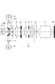
図1に露光装置の概略図を示す。露光装置は、光源装置からの光を用いて、被照明面にあるマスク(レチクル)8を照明し、マスク8のパターンを投影光学系9により基板(ウエハ、ガラスプレート等)10上に投影して露光する。
(Embodiment 1)
FIG. 1 shows a schematic view of an exposure apparatus. The exposure apparatus illuminates the mask (reticle) 8 on the surface to be illuminated using light from the light source device, and projects the pattern of the
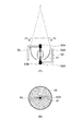
光源装置は、複数の光源部1A、1B、1Cを有する。各光源部の詳細図を図2に示す。各光源部は、水銀ランプ51と、水銀ランプ51からの光を集光する楕円ミラー(凹面の反射鏡)50と、水銀ランプ51の陽極(電極)52Aに接続されたケーブル53Aと陰極(電極)52Bに接続されたケーブル53Bと有する。水銀ランプ51は、陽極52Aと陰極52Bの間に超高電圧の電圧をかけることにより発光する。発光すると、水銀ランプ51自身が発熱するため、周囲の温度が600℃近傍になり、それ以上なると水銀ランプのバルブが破裂してしまう。特に、水銀ランプ51の陽極52A(口金部)と水銀ランプ陰極52B(口金部)の発熱が著しい。この部位の温度上昇を防ぐため、光源部には、陽極52Aを冷却するための冷却ノズル54Aおよび陰極52Bを冷却するための冷却ノズル54Bが設けられている。これらの冷却ノズルから冷却用圧縮空気が陽極52Aと陰極52Bに吹き付けられており、水銀ランプ51が所望の温度を維持できるような構造となっている。楕円ミラー50の第一焦点と水銀ランプ51の発光点は一致するように配置されており、水銀ランプ51からの光は楕円ミラー50で第二焦点55に集光されている。
The light source device includes a plurality of
露光装置は、複数の光源部1A、1B、1Cからの光を用いてマスク8を照明する照明光学系20を有する。照明光学系20は、レンズ11A、11B、11C、及び、ミラー2から結像光学系7を有する。光源部1A、1B、1Cからの光は、それぞれレンズ11A、11B、11Cを通過する。次に、レンズ11A、11Cを通過した光は偏向ミラー2で反射され、光路が折り曲げられる。その後、フーリエ変換光学系(コリメータ)3によって、複数の光源部からの光が合成される。具体的には、フーリエ変換光学系3によって、偏向ミラー2で反射された光と、レンズ11Bを通過した光は、ハエの目レンズ4に導かれる。フーリエ変換光学系3は、光源部1A、1B、1C内に配置されている楕円ミラー50の第二焦点位置とハエの目レンズ4の入射面とが互いにフーリエ共役面(フーリエ変換の関係の面)になるように配置されている。そのため、各光源部からの光はフーリエ変換光学系3により、ハエの目レンズ4の入射面においてほぼ同じ領域に入射して、各光源部からの光が重畳するようになっている。
The exposure apparatus includes an illumination
ハエの目レンズ4の射出面が照明光学系の瞳面となっており、ここでは、その瞳面における光強度分布を有効光源分布と称する。この瞳面に、各光源部からの光を重畳した光強度分布を形成している。その後、ハエの目レンズ4の射出面から出た光はフーリエ変換光学系5を通過し、スリット(開口)が設けられた視野絞り6に入射する。視野絞り6とマスク8および基板10とは光学的に共役面となるよう、それぞれ結像光学系7および投影光学系9が配置されている。そのため、有効光源分布は、マスクのある1点に入射する光の角度分布に相当する。そして、スリットを通過した光でマスク8を照明し、投影光学系9により基板10上にマスク8のパターンを投影する。なお、複数の光源部1A、1B、1Cと照明光学系20が、マスク(被照明面)を照明する照明装置を構成する。
The exit surface of the fly-
図3(A)に、図2のA―Aから矢印方向に光源部を見た矢視図を示す。水銀ランプ51から発光する光は、楕円ミラー50で反射された後、レンズ11A、11B又は11Cに向かうが、その途中で一部の光が冷却ノズル54A(遮光部材)とケーブル53A(遮光部材)で遮られる。そのため、有効光源分布において、冷却ノズル54Aとケーブル53Aの影が生じる。図3(B)に、図2のA―A断面における光束の光強度分布を示す。円形の光強度分布内において、所定の光強度の領域60の他に、ケーブル53Aの影63と冷却ノズル54Aの影64がある。そのため、有効光源分布において、ケーブル53Aの影と冷却ノズル54Aの影が存在し、領域60における光強度よりも光強度が低い部分が生じてしまう。説明を簡易的に行うため、領域60の光強度を100%とし、影63、64の部分の光強度を0%としている。なお、水銀ランプ51の発光点からの光が水銀ランプ51の陽極52Aで遮光されて、有効光源分布の中心に陽極52Aの影62ができる。ただし、陽極52Aは水銀ランプ51の一部であって、水銀ランプ51の陽極52Aの影と、水銀ランプ51からの光であって楕円ミラー50で反射されてマスクに向かう光を遮る遮光部材の影とは区別している。
FIG. 3A shows an arrow view of the light source section viewed from AA in FIG. 2 in the arrow direction. The light emitted from the
本露光装置は、3つの光源部1A、1B、1Cを有している。それぞれ光源部には、冷却ノズル54Aとケーブル53Aがあるため、有効光源分布において、複数の光源部の冷却ノズル54Aとケーブル53Aの影が生じる。
The present exposure apparatus has three
まず、比較例を説明する。図4に比較例を示す。図4(A)のように、光源部1A、1B、1Cからの光束の断面における光強度分布がそれぞれ60A、60B、60Cとなるように各光源部が配置されている。前述のように、各光強度分布60A、60B、60Cには、遮光部材の影(黒色部分)が存在する。光源部1A、1B、1Cからハエの目レンズ4までのレンズやミラーよる反転と回転を考慮すると、各光強度分布60A、60B、60Cはそれぞれ、図4(B)のように、照明光学系の瞳面において各光強度分布61A、61B、61Cとなる。有効光源分布は、各光強度分布61A、61B、61Cが合成された光であるため、各光強度分布61A、61B、61Cを足し合わせた光強度分布100Aとなる。光強度分布100Aは、光強度が300%の領域70と、光強度が0%の影の領域71を有し、強度ムラが発生している。このような不均一な有効光源分布でマスクを照明し、基板上にマスクのパターンを露光すると、良好な解像性能(線幅、線幅均一性、フォーカス、歪みなど)を得ることができない。
First, a comparative example will be described. FIG. 4 shows a comparative example. As shown in FIG. 4A, the light source parts are arranged so that the light intensity distributions in the cross sections of the light beams from the
次に、本実施形態の実施例を以下に説明する。 Next, examples of the present embodiment will be described below.
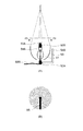
図5(A)のように、光源部1A、1B、1Cからの光束の断面における光強度分布がそれぞれ80A、80B、80Cとなるように各光源部が配置されている。比較例と同様に、各光強度分布80A、80B、80Cには、遮光部材の影(黒色部分)が存在する。しかし、本実施例では、上記比較例とは、遮光部材の影の位置が異なる。各光強度分布80A、80B、80Cでは、ケーブル53Aの影と冷却ノズル54Aの影が中心角60°隔てて存在する。光源部1A、1B、1Cからハエの目レンズ4までのレンズやミラーよる反転と回転を考慮すると、各光強度分布80A、80B、80Cはそれぞれ、図5(B)のように、照明光学系の瞳面において各光強度分布81A、81B、81Cとなる。有効光源分布は、各光強度分布81A、81B、81Cが合成された光であるため、各光強度分布81A、81B、81Cを足し合わせた光強度分布100となる。光強度分布100には、遮光部材の影が中心角60の等しい間隔で生じている。
As shown in FIG. 5A, the light source units are arranged so that the light intensity distributions in the cross sections of the light beams from the
本実施例では、照明光学系の瞳面における該合成された光の強度分布において、複数の光源部のうち1つの光源部の遮光部材の影の位置が、複数の光源部のうちその他の光源部の遮光部材の影の位置に対してずれている。具体的には、有効光源分布において、光源部1Aの遮光部材の影83A、84Aの位置が、光源部1Bの遮光部材の影83B、84Bの位置、および、光源部1Cの遮光部材の影83C、84Cの位置に対してずれている。そのため、光強度分布100は、光強度が300%の領域80と、遮光部材の影がある光強度が200%の領域85(黒色)を有する。このように、有効光源分布における影の位置が分散されていることによって、有効光源分布において光強度の偏りが解消し、その結果、マスクのパターンの解像性能が低下するのを抑えることができる。
In this embodiment, in the intensity distribution of the combined light on the pupil plane of the illumination optical system, the position of the shadow of the light blocking member of one light source unit among the plurality of light source units is the other light source among the plurality of light source units. It is shifted with respect to the position of the shadow of the light shielding member. Specifically, in the effective light source distribution, the positions of the
図6(A)のように、光源部1A、1B、1Cからの光束の断面における光強度分布がそれぞれ90A、90B、90Cとなるように各光源部が配置されている。各光強度分布90A、90B、90Cには、遮光部材の影(黒色部分)が存在する。実施例1では、各光源部の冷却ノズル54Aとケーブル53Aとなす角度は60°であったが、本実施例では、各光源部の冷却ノズル54Aとケーブル53Aが対向するように、すなわち、なす角度180°となるように配置されている。そのため、本実施例では、実施例1とは、遮光部材の影の位置が異なる。各光強度分布90A、90B、90Cでは、ケーブル53Aの影と冷却ノズル54Aの影が中心角180°隔てて存在する。光源部1A、1B、1Cからハエの目レンズ4までのレンズやミラーよる反転と回転を考慮すると、各光強度分布90A、90B、90Cはそれぞれ、図6(B)のように、照明光学系の瞳面において各光強度分布91A、91B、91Cとなる。有効光源分布は、各光強度分布91A、91B、91Cが合成された光であるため、各光強度分布91A、91B、91Cを足し合わせた光強度分布200となる。実施例1の光強度分布100と同様に、光強度分布200には、遮光部材の影が中心角60の等しい間隔で生じている。
As shown in FIG. 6A, the light source units are arranged so that the light intensity distributions in the cross sections of the light beams from the
本実施例では、実施例1と同様に、照明光学系の瞳面における該合成された光の強度分布において、複数の光源部のうち1つの光源部の遮光部材の影の位置が、複数の光源部のうちその他の光源部の遮光部材の影の位置に対してずれている。具体的には、有効光源分布において、光源部1Aの遮光部材の影93A、94Aの位置が、光源部1Bの遮光部材の影93B、94Bの位置、および、光源部1Cの遮光部材の影93C、94Cの位置に対してずれている。そのため、実施例1と同様に、有効光源分布において光強度の偏りが解消し、その結果、マスクのパターンの解像性能が低下するのを抑えることができる。
In the present embodiment, as in the first embodiment, in the intensity distribution of the combined light on the pupil plane of the illumination optical system, the position of the shadow of the light blocking member of one light source section among the plurality of light source sections is a plurality of positions. It is shifted with respect to the position of the shadow of the light shielding member of the other light source unit among the light source units. Specifically, in the effective light source distribution, the positions of the
実施例1、2では、照明装置は光源部を複数有し、光源部の数が3、各光源部の遮光部材の数が2であったが、数はこれに限らない。冷却ノズル54Aやケーブル53Aをそれぞれ、1つの影を形成する遮光部材と捉え、光源部1つあたりの遮光部材の数をm(整数)、光源部の数をk(整数)とする。有効光源分布において遮光部材の全ての影が重ならずにずれている場合、影の数nはn=m×kとなる。図7に示すように、影の位置はA=360°/nの等しい中心角間隔でずれていることが好ましい。
In the first and second embodiments, the lighting device has a plurality of light source units, the number of light source units is 3, and the number of light shielding members in each light source unit is 2, but the number is not limited to this. Each of the cooling
ただし、図7のように影の位置が全く等しい中心角間隔でずれている場合だけではなく、等しい中心角間隔からずれていてもよい。例えば、図8に示すように、照明光学系の瞳面を360°/nの中心角で分割したn個の部分領域110A〜110Fに分割し、それぞれの部分領域に遮光部材の影が存在するように、各光源部の遮光部材を配置してもよい。また、有効光源分布における遮光部材の影同士の間隔が、360°/nの半分、つまり、180°/nの中心角以上であると、有効光源分布において複数の影が偏らずに分散されるため好ましい。
However, not only when the positions of the shadows are deviated at exactly the same center angle interval as shown in FIG. 7, they may be deviated from the same center angle interval. For example, as shown in FIG. 8, the pupil plane of the illumination optical system is divided into n
光源部の電流方向を逆転した場合は陰極と陽極が上下反対となるため、図2において、陽極52Aの冷却ノズル54Aと陽極52Aに接続されるケーブル53Aと、陰極52Bの冷却ノズル54Bと陰極52Bに接続されるケーブル53Bは上下反対になる。その場合、冷却ノズル54Bとケーブル53Bが、楕円ミラー50で反射されてマスクに向かう光を遮る遮光部材である。
When the current direction of the light source is reversed, the cathode and the anode are turned upside down. Therefore, in FIG. 2, the cooling
また、特許文献2のように、光源部が冷却ノズルとケーブルが一体となった部材を有していてもよい。図9(A)に、冷却ノズルとケーブルが一体となった部材を有する光源部の図を示す。光源部は、冷却ノズル54Aの中にケーブル53Aが収容された部材56(遮光部材)を有する。光源部をA―Aから見た矢視図を図9(B)に示す。冷却ノズルとケーブルが一体となっているため、楕円ミラー50で反射された光束の断面における光強度分布には、一体となった部材の1つの影ができる。そのため、冷却ノズルとケーブルが別体であって影が2つできる場合よりも、光源からの光の光量損失が低くてすむ。この場合であっても、有効光源分布において、各光源部の冷却ノズルとケーブルが一体となった遮光部材の影の位置が、実施例1、2のように、それぞれの光源部の遮光部材の影の位置に対して互いにずれているように、各光源部が配置される。
Further, as in
また、冷却ノズルとケーブルが別体であっても、有効光源分布において冷却ノズルの影とケーブルの影が重なっているように、光源部内において冷却ノズルとケーブルを配置してもよい。例えば、図10(A)、(B)に示すように、冷却ノズル54Aの影とケーブル53Aの影とが重なって1つの影65を形成するように、冷却ノズル54Aとケーブル53Aを配置してもよい。影を形成する冷却ノズル54Aとケーブル53Aの幅は同じであることが望ましい。構造的に不可能である場合は、有効光源分布における冷却ノズル54Aの影とケーブル53Aの影との幅が同じになるように、光の進行方向における冷却ノズル54Aとケーブル53Aの相対的な位置を予め調整して配置してもよい。ここで、光の進行方向は、楕円ミラー50の第一焦点と第二焦点を結ぶ線分に平行な方向である。
Even if the cooling nozzle and the cable are separate, the cooling nozzle and the cable may be arranged in the light source unit so that the shadow of the cooling nozzle and the shadow of the cable overlap in the effective light source distribution. For example, as shown in FIGS. 10A and 10B, the cooling
(実施形態2)
図11に、第2の実施形態の露光装置の概略図を示す。本実施形態の露光装置は、実施形態1の露光装置とは、計測部500と調整部(制御部600と調整機構700A、700B、700C)とを有する点で異なる。実施形態1と同様の構成については説明を省略する。
(Embodiment 2)
FIG. 11 shows a schematic diagram of an exposure apparatus according to the second embodiment. The exposure apparatus of this embodiment is different from the exposure apparatus of Embodiment 1 in that it includes a
本実施形態では、視野絞り6の遮光板に、有効光源分布を計測する計測部500が設けられている。計測部500は、視野絞り6の遮光板に設けられたピンホール(開口)を通過した光を2次元の撮像素子(CCDなど)で計測する。撮像素子上には、ピンホールに入射する光の角度分布(入射角毎の光線強度)に応じて、光強度分布が形成される。したがって、撮像素子で計測された光強度分布が有効光源分布に相当する。また、本実施形態の照明装置は、制御部600と、光源部1A、1B、1Cの角度や位置の配置を調整する調整機構700A、700B、700Cとを有する。各調整機構は制御部600の制御指令に基づいて駆動される。
In the present embodiment, a
次に、照明装置の調整方法について説明する。図12に調整方法のフローチャートを示す。まず、S102で、計測部500を用いて有効光源分布を計測する。次に、S104で、制御部600は、計測部500により計測された有効光源分布を評価する。制御部600は、計測部500による有効光源分布の計測結果のデータを取得し、そのデータをもとに、例えば、有効光源分布において光強度が低い部分、つまり、光源部の遮光部材の影の位置を特定する。
Next, a method for adjusting the lighting device will be described. FIG. 12 shows a flowchart of the adjustment method. First, in S102, the effective light source distribution is measured using the
次に、S106で、S104での評価結果に基づいて光源部の遮光部材の配置を調整する。例えば、S104で、有効光源分布内で光源部の遮光部材の複数の影が重なっていると評価された場合には、重なっている影に対応する遮光部材を有する光源部の楕円ミラーの長軸周りの回転角度や遮光部材の位置などの配置を調整する。具体的には、制御部600による評価結果、光源部1Aの遮光部材の影と光源部1Bの遮光部材の影とが重なっていると特定した場合には、光源部1Aの遮光部材の配置を光源部1Bの遮光部材の配置に対して相対的に調整する。例えば、制御部600は、光源部1Aの遮光部材の影の位置と光源部1Bの遮光部材の影の位置がずれるように調整機構700Aに指令を送り、調整機構700Aが光源部1Aの楕円ミラーの長軸周りの回転角度を調整する。または、光源部1A内における遮光部材の取り付け位置を変更してもよい。
Next, in S106, the arrangement of the light shielding members of the light source unit is adjusted based on the evaluation result in S104. For example, when it is evaluated in S104 that a plurality of shadows of the light shielding member of the light source unit overlap within the effective light source distribution, the major axis of the elliptic mirror of the light source unit having the light shielding member corresponding to the overlapping shadow The arrangement of the surrounding rotation angle and the position of the light shielding member is adjusted. Specifically, when the evaluation result by the control unit 600 indicates that the shadow of the light shielding member of the
また、S104の評価において、有効光源分布内の互いに垂直な2方向のそれぞれに沿って、各位置における光強度を積算して積算強度値を算出する。そして、S106において、その積算強度値に基づいて、有効光源分布内の互いに垂直な2方向における強度差が小さくなるように、各光源部の配置を調整してもよい。または、S104の評価において、有効光源分布内の分割された部分領域ごとに、光強度の合計値を算出し、各部分領域における光強度分布のばらつき具合を算出し、S106において、そのばらつき具合に基づいて、各光源部の配置を調整してもよい。 In the evaluation in S104, the integrated intensity value is calculated by integrating the light intensity at each position along each of two mutually perpendicular directions in the effective light source distribution. In S106, the arrangement of the light source units may be adjusted based on the integrated intensity value so that the intensity difference in two directions perpendicular to each other in the effective light source distribution becomes small. Alternatively, in the evaluation in S104, the total value of the light intensity is calculated for each of the divided partial areas in the effective light source distribution, and the degree of variation in the light intensity distribution in each partial area is calculated. In S106, the degree of variation is calculated. Based on this, the arrangement of the light source units may be adjusted.
次に、S108で、調整された有効光源分布を用いて露光処理を行う。露光処理は、マスク8を照明し、投影光学系9を介してマスク8のパターンを基板10上に投影することにより行う。
Next, in S108, an exposure process is performed using the adjusted effective light source distribution. The exposure process is performed by illuminating the
この調整方法は、露光装置上で定期的に行ってもよいし、装置の出荷前の校正として行ってもよい。本実施形態によれば、有効光源分布を計測して高精度に調整が行えることから、有効光源分布において光強度の偏りが解消し、その結果、複数の光源部の遮光部材の影によってマスクのパターンの解像性能が低下するのを、より確実に抑えることができる。 This adjustment method may be performed periodically on the exposure apparatus, or may be performed as a calibration prior to shipment of the apparatus. According to this embodiment, since the performed adjustment on the measured highly accurately the effective light source distribution to overcome a bias of the light intensity in the effective light source distribution, so that the mask by the shadow of the shielding member of the plurality of light source sections from resolution performance of the pattern is reduced, it is possible to reliably inhibit Ri good.
(実施形態3)
本実施形態における露光装置の構成は実施形態2と同様であるため、説明を省略する。なお、本実施形態では、調整方法において実施形態2と異なる。図13に、実施形態3における調整方法のフローチャートを示す。
(Embodiment 3)
Since the configuration of the exposure apparatus in the present embodiment is the same as that in the second embodiment, description thereof is omitted. Note that the present embodiment differs from the second embodiment in the adjustment method. FIG. 13 shows a flowchart of the adjustment method in the third embodiment.
まず、S202で、露光装置の制御部600は、マスク8のパターンの情報を取得する。マスク8のパターンの情報は、ユーザーによって入力装置から入力されてもよいし、外部の装置から自動で入力されてもよい。次に、S204で、制御部600は、マスク8のパターンの情報から、マスク8に含まれる少なくとも1つのパターンの方向を特定する。図14(A)、(B)に、マスク8のパターンの例を示す。図14(A)のマスクは、x方向に周期的に並んだy方向に長いラインパターンP11、P13と、y方向に周期的に並んだx方向に長いラインを有するラインパターンP12、P14と、を含む。図14(B)のマスクは、x方向、y方向から斜め45°傾いた方向に周期的に並んだパターンP21〜P24を含む。これらのマスクのパターンの方向として、周期方向またはパターンの長手方向を特定する。
First, in step S <b> 202, the control unit 600 of the exposure apparatus acquires pattern information of the
次に、S206で、特定した方向の情報に基づいて光源部の遮光部材の配置を調整する。図14(A)のマスクのように、x又はy方向に周期的に並んだパターンがある場合には、投影光学系9にはマスクからx方向又はy方向に回折光が生じて、これらの回折光が基板10面上で結像する。そのため、図15(B)に示す有効光源分布よりも、図15(A)に示すように、x方向又はy方向に延びる遮光部材の影がある有効光源分布を用いてマスクを照明した方がよい。なお、図15(A)、(B)に示す有効光源分布内の黒帯部分が光源部の遮光部材の影である。一方、図14(B)のマスクのように、斜め方向に周期的に並んだパターンがある場合には、投影光学系9にはマスクから斜め方向に回折光が生じて、これらの回折光が基板10面上で結像する。そのため、図15(A)に示す有効光源分布よりも、図15(B)に示すように、斜め方向に延びる遮光部材の影がある有効光源分布を用いてマスクを照明した方がよい。有効光源分布において光強度や影が偏ると、回折光の結像性能が回折光の生じる方向により異なり、基板上での解像性能に差が生ずるのが原因である。周期方向が異なる複数の周期パターンを有するマスクにおいて、良好な解像性能を得るためには、複数の周期パターン間で周期方向(つまり、回折光の生ずる方向)が異なっていても回折光の結像性能があまり変わらないような有効光源分布で照明することが望ましい。
Next, in S206, the arrangement of the light blocking members of the light source unit is adjusted based on the information on the specified direction. When there is a pattern periodically arranged in the x or y direction as in the mask in FIG. 14A, diffracted light is generated in the projection optical system 9 in the x or y direction, and these patterns are generated. Diffracted light forms an image on the surface of the
光源部の遮光部材の配置の調整は、例えば、調整機構により、光源部1A、1B、1Cの取り付け位置および取り付け角度の調整を行い、マスクのパターンに応じて、有利な解像性能を示すよう有効光源分布における光源部の遮光部材の影の位置を変える。例えば、図14(A)のマスクのパターンの場合には、図15(A)に示す有効光源分布となるように光源部の遮光部材の配置を調整し、図14(B)のマスクのパターンの場合には、図15(B)に示す有効光源分布となるように光源部の遮光部材の配置を調整する。また、光源部1A、1B、1Cの調整の確認のために、実施形態2における有効光源分布の計測および有効光源分布の調整を併せて行ってもよい。
Adjustment of the arrangement of the light-shielding member of the light source unit is performed, for example, by adjusting the mounting position and mounting angle of the
本実施形態では、マスクが互いに周期方向が異なる2種のパターンを備える場合について調整を行ったが、様々なパターンにおいても適用可能である。 In the present embodiment, the adjustment is performed when the mask includes two types of patterns having different periodic directions, but the present invention can also be applied to various patterns.
本実施形態によれば、有効光源分布において光源部の遮光部材の影が生じている場合であっても、マスクのパターンに適当な有効光源分布を用いることにより、マスクのパターンの解像性能が低下するのを抑えることができる。 According to this embodiment, even when the shadow of the light shielding member of the light source unit is generated in the effective light source distribution, the resolution performance of the mask pattern is improved by using an appropriate effective light source distribution for the mask pattern. It is possible to suppress the decrease.
なお、上記実施形態では、光源を水銀ランプ51としたが、光源の種類はこれに限らない。また、反射鏡としては、楕円ミラーに限らず、放物面鏡や、平面鏡を並べたミラーでもよい。また、有効光源分布の形状にも限定はなく、輪帯照明や多重極照明など様々な照明も適用可能である。また、露光装置は、マスクを保持するステージ及び基板を保持するステージを移動しながら露光する走査型露光装置でも、マスクのパターンを一括して基板を露光するステッパでも適用可能である。
In the above embodiment, the light source is the
また、上記実施形態の照明装置は、露光装置以外にも適用できる。例えば、液晶プロジェクターの照明装置にも適用できる。 Moreover, the illumination device of the above embodiment can be applied to devices other than the exposure device. For example, the present invention can be applied to a lighting device for a liquid crystal projector.
(実施形態4)
次に、前述の露光装置を利用した物品(半導体IC素子、液晶表示デバイス、カラーパネル等)の製造方法を説明する。物品は、前述の露光装置を使用して、感光剤が塗布された基板(ウェハ、ガラス基板等)を露光する工程と、その基板(感光剤)を現像する工程と、他の周知の工程と、を経ることにより製造される。他の周知の工程には、エッチング、レジスト剥離、ダイシング、ボンディング、パッケージング等の加工が含まれる。本物品製造方法によれば、従来よりも高品位の物品を製造することができる。
(Embodiment 4)
Next, a method for manufacturing an article (semiconductor IC element, liquid crystal display device, color panel, etc.) using the above-described exposure apparatus will be described. The article includes a step of exposing a substrate (wafer, glass substrate, etc.) coated with a photosensitive agent using the exposure apparatus described above, a step of developing the substrate (photosensitive agent), and other well-known steps. It is manufactured by going through. Other well-known processes include processes such as etching, resist stripping, dicing, bonding, and packaging. According to this article manufacturing method, it is possible to produce an article of higher quality than ever.
Claims (16)
ランプと、前記ランプからの光を反射する反射鏡と、前記反射鏡の外側から前記ランプの電極に接続されたケーブルと、前記反射鏡の外側から前記ランプの電極に向かって延び、前記ランプの電極を冷却するための冷却ノズルと、を含む光源部を複数有し、
前記複数の光源部からの光を重畳した光強度分布を瞳面に形成し、重畳した光で前記被照明面を照明する照明光学系を更に有し、
前記反射鏡で反射されて前記被照明面に向かう光の一部を前記ケーブル及び前記冷却ノズルが遮ることにより、前記照明光学系の瞳面における光強度分布において前記ケーブル及び前記冷却ノズルのそれぞれの影が形成され、
前記照明光学系の瞳面における光強度分布において、前記複数の光源部のうち1つの光源部の前記ケーブル及び前記冷却ノズルのそれぞれの影の位置、及び、前記複数の光源部のうちその他の少なくとも1つの光源部の前記ケーブル及び前記冷却ノズルのそれぞれの影の位置が互いにずれていることを特徴とする照明装置。 An illumination device for illuminating a surface to be illuminated,
Lamp and a reflecting mirror for reflecting light from the lamp, a cable from the outside of the reflector are connected to the electrodes of the lamp, extending from the outside of the reflecting mirror toward the electrode of the lamp, the lamp A plurality of light source parts including a cooling nozzle for cooling the electrode ,
A light intensity distribution in which light from the plurality of light source units is superimposed is formed on a pupil plane, and further includes an illumination optical system that illuminates the illuminated surface with the superimposed light,
Each of the cables and the cooling nozzles in the light intensity distribution on the pupil plane of the illumination optical system is blocked by the cables and the cooling nozzles blocking a part of the light reflected by the reflecting mirror and traveling toward the illuminated surface. A shadow is formed,
In the light intensity distribution on the pupil plane of the illumination optical system, the shadow position of each of the cable and the cooling nozzle of one of the plurality of light source units, and at least the other of the plurality of light source units. The lighting device characterized in that the positions of the shadows of the cable and the cooling nozzle of one light source unit are shifted from each other .
前記計測部によって計測された光強度分布に基づいて、前記照明光学系の瞳面における光強度分布における影の位置を調整する調整部と、
を更に有することを特徴とする請求項1乃至6の何れか1項に記載の照明装置。 A measuring unit for measuring the light intensity distribution in a pupil plane before Symbol illumination optical system,
On the basis of the light intensity distribution measured by the measurement unit, an adjustment unit for adjusting the position of the shadow that put on the light intensity distribution in a pupil plane of the illumination optical system,
The lighting device according to claim 1 , further comprising:
前記反射鏡で反射されて前記被照明面に向かう光の一部を前記ケーブル及び前記冷却ノズルが遮ることにより前記照明光学系の瞳面における光強度分布に形成される前記ケーブル及び前記冷却ノズルのそれぞれの影の位置を調整する工程
を有し、
前記照明光学系の瞳面における光強度分布において、前記複数の光源部のうち1つの光源部の前記ケーブル及び前記冷却ノズルのそれぞれの影の位置、及び、前記複数の光源部のうちその他の少なくとも1つの光源部の前記ケーブル及び前記冷却ノズルのそれぞれの影の位置が互いにずれるように、前記影の位置を調整することを特徴とする調整方法。 Lamp and a reflecting mirror for reflecting light from the lamp, a cable from the outside of the reflector are connected to the electrodes of the lamp, extending from the outside of the reflecting mirror toward the electrode of the lamp, the lamp A plurality of light source units each having a cooling nozzle for cooling the electrode; a light intensity distribution in which light from the plurality of light source units is superimposed is formed on a pupil plane; and the surface to be illuminated is illuminated with the superimposed light An illumination optical system further comprising: an illumination optical system adjustment method comprising:
The cable and the cooling nozzle formed in the light intensity distribution on the pupil plane of the illumination optical system by blocking a part of the light reflected by the reflecting mirror and going to the illuminated surface by the cable and the cooling nozzle . It has a step of adjusting the position of each shadow,
In the light intensity distribution on the pupil plane of the illumination optical system, the shadow position of each of the cable and the cooling nozzle of one of the plurality of light source units, and at least the other of the plurality of light source units. An adjustment method comprising adjusting the positions of the shadows so that the positions of the shadows of the cable and the cooling nozzle of one light source unit are shifted from each other .
該計測された光強度分布に基づいて前記影の位置を調整する工程と、を有することを特徴とする請求項10に記載の調整方法。The adjustment method according to claim 10, further comprising: adjusting the position of the shadow based on the measured light intensity distribution.
前記マスクのパターンの情報に基づいて、前記照明光学系の瞳面における光強度分布における前記影の位置を調整することを特徴とする請求項10又は11に記載の調整方法。 The illumination optical system illuminates a mask on the illuminated surface,
Based on the information of the pattern of the mask, adjustment method according to claim 10 or 11, characterized in that you adjust the position of the pre-Symbol shadow in the light intensity distribution in a pupil plane of the illumination optical system.
前記調整工程において、該取得した前記マスクのパターンの方向の情報に基づいて前記影の位置を調整することを特徴とする請求項12に記載の調整方法。 Obtaining information on the direction of the pattern of the mask;
13. The adjustment method according to claim 12 , wherein, in the adjustment step, the position of the shadow is adjusted based on the acquired information on the direction of the pattern of the mask.
被照明面としてのマスクを、照明光学系の瞳面に形成される複数の影を含む光強度分布を用いて照明する、請求項1乃至9の何れか1項に記載の照明装置と、
前記照明装置により照明された前記マスクのパターンを前記基板上に投影する投影光学系と、を有することを特徴とする露光装置。 An exposure apparatus that exposes a mask pattern onto a substrate,
The illumination device according to any one of claims 1 to 9 , wherein a mask as an illuminated surface is illuminated using a light intensity distribution including a plurality of shadows formed on a pupil plane of an illumination optical system ;
An exposure apparatus comprising: a projection optical system that projects the pattern of the mask illuminated by the illumination device onto the substrate.
露光された基板を現像する工程と、
現像された基板を加工して物品を製造する工程とを有することを特徴とする物品の製造方法。 Exposing the substrate using the exposure apparatus according to claim 15 ;
Developing the exposed substrate;
And a step of manufacturing the article by processing the developed substrate.
Priority Applications (5)
| Application Number | Priority Date | Filing Date | Title |
|---|---|---|---|
| JP2014124752A JP6362095B2 (en) | 2014-06-17 | 2014-06-17 | Illumination apparatus, exposure apparatus, adjustment method, and article manufacturing method |
| TW104118491A TWI587097B (en) | 2014-06-17 | 2015-06-08 | Illumination device, exposure apparatus, adjusting method, and method for manufacturing object |
| US14/740,071 US9632423B2 (en) | 2014-06-17 | 2015-06-15 | Illumination device, exposure apparatus, adjusting method, and method for manufacturing object |
| KR1020150084943A KR101850584B1 (en) | 2014-06-17 | 2015-06-16 | Illumination device, exposure apparatus, adjusting method, and method for manufacturing object |
| CN201510336459.3A CN105278258B (en) | 2014-06-17 | 2015-06-17 | Illuminating device, exposure device, method of adjustment and the method for manufacturing article |
Applications Claiming Priority (1)
| Application Number | Priority Date | Filing Date | Title |
|---|---|---|---|
| JP2014124752A JP6362095B2 (en) | 2014-06-17 | 2014-06-17 | Illumination apparatus, exposure apparatus, adjustment method, and article manufacturing method |
Publications (3)
| Publication Number | Publication Date |
|---|---|
| JP2016004921A JP2016004921A (en) | 2016-01-12 |
| JP2016004921A5 JP2016004921A5 (en) | 2017-07-27 |
| JP6362095B2 true JP6362095B2 (en) | 2018-07-25 |
Family
ID=54836065
Family Applications (1)
| Application Number | Title | Priority Date | Filing Date |
|---|---|---|---|
| JP2014124752A Active JP6362095B2 (en) | 2014-06-17 | 2014-06-17 | Illumination apparatus, exposure apparatus, adjustment method, and article manufacturing method |
Country Status (5)
| Country | Link |
|---|---|
| US (1) | US9632423B2 (en) |
| JP (1) | JP6362095B2 (en) |
| KR (1) | KR101850584B1 (en) |
| CN (1) | CN105278258B (en) |
| TW (1) | TWI587097B (en) |
Families Citing this family (2)
| Publication number | Priority date | Publication date | Assignee | Title |
|---|---|---|---|---|
| DE202016103819U1 (en) * | 2016-07-14 | 2017-10-20 | Suss Microtec Lithography Gmbh | Light source arrangement for an exposure system and photolithography exposure system |
| CN107179653B (en) * | 2017-07-20 | 2018-10-19 | 武汉华星光电技术有限公司 | A kind of exposure machine and its light-emitting device |
Family Cites Families (18)
| Publication number | Priority date | Publication date | Assignee | Title |
|---|---|---|---|---|
| JP2899026B2 (en) | 1989-11-27 | 1999-06-02 | 株式会社日立製作所 | Mark detection device |
| US5305054A (en) * | 1991-02-22 | 1994-04-19 | Canon Kabushiki Kaisha | Imaging method for manufacture of microdevices |
| JP2890892B2 (en) * | 1991-04-30 | 1999-05-17 | キヤノン株式会社 | Exposure apparatus and element manufacturing method using the same |
| JP2633091B2 (en) * | 1991-02-22 | 1997-07-23 | キヤノン株式会社 | Image projection method, circuit manufacturing method, and projection exposure apparatus |
| CN1045103C (en) | 1994-06-18 | 1999-09-15 | 兰州炼油化工总厂三星公司 | Alkyl salicylate as additive of lubricant oil |
| JP2000075496A (en) * | 1998-08-31 | 2000-03-14 | Canon Inc | Light source provided with cooling mechanism, light source device and exposure device using the same |
| JP2000098099A (en) * | 1998-09-21 | 2000-04-07 | Nikon Corp | X-ray illumination device and x-ray projection exposure device |
| US6704090B2 (en) * | 2000-05-11 | 2004-03-09 | Nikon Corporation | Exposure method and exposure apparatus |
| JP2001326171A (en) * | 2000-05-18 | 2001-11-22 | Canon Inc | Illumination apparatus |
| DE60217771T3 (en) * | 2001-07-27 | 2012-02-09 | Canon K.K. | Exposure system, projection exposure apparatus and method of making an article |
| JP2004063988A (en) * | 2002-07-31 | 2004-02-26 | Canon Inc | Illumination optical system, aligner having the system, and method of manufacturing device |
| JP4086582B2 (en) * | 2002-08-06 | 2008-05-14 | キヤノン株式会社 | Illumination apparatus and exposure apparatus |
| JP2004079254A (en) * | 2002-08-13 | 2004-03-11 | Canon Inc | Light source equipment and exposure device |
| JP4470558B2 (en) * | 2004-03-31 | 2010-06-02 | ウシオ電機株式会社 | Light irradiation device |
| TWI401538B (en) | 2007-03-28 | 2013-07-11 | Orc Mfg Co Ltd | Exposure drawing device |
| EP2985526B1 (en) | 2007-04-12 | 2019-07-24 | Nikon Corporation | Discharge lamp, light source apparatus, and exposure apparatus |
| JP4921512B2 (en) * | 2009-04-13 | 2012-04-25 | キヤノン株式会社 | Exposure method, exposure apparatus, and device manufacturing method |
| CN102985874B (en) | 2010-08-23 | 2015-03-25 | 三菱电机株式会社 | Projection display device |
-
2014
- 2014-06-17 JP JP2014124752A patent/JP6362095B2/en active Active
-
2015
- 2015-06-08 TW TW104118491A patent/TWI587097B/en active
- 2015-06-15 US US14/740,071 patent/US9632423B2/en active Active
- 2015-06-16 KR KR1020150084943A patent/KR101850584B1/en active IP Right Grant
- 2015-06-17 CN CN201510336459.3A patent/CN105278258B/en active Active
Also Published As
| Publication number | Publication date |
|---|---|
| TW201600936A (en) | 2016-01-01 |
| TWI587097B (en) | 2017-06-11 |
| KR101850584B1 (en) | 2018-04-19 |
| US20150362843A1 (en) | 2015-12-17 |
| JP2016004921A (en) | 2016-01-12 |
| CN105278258A (en) | 2016-01-27 |
| KR20150144711A (en) | 2015-12-28 |
| CN105278258B (en) | 2017-10-24 |
| US9632423B2 (en) | 2017-04-25 |
Similar Documents
| Publication | Publication Date | Title |
|---|---|---|
| JP5854084B2 (en) | Illumination optical system, exposure apparatus, and device manufacturing method | |
| TW200839460A (en) | Exposure apparatus and semiconductor device fabrication method | |
| TWI815848B (en) | Exposure device and exposure method | |
| JP6651124B2 (en) | Illumination optical system, exposure apparatus, and device manufacturing method | |
| JP6362095B2 (en) | Illumination apparatus, exposure apparatus, adjustment method, and article manufacturing method | |
| JP2008181980A (en) | Method of adjusting/evaluating light intensity distribution of lighting device, lighting device, exposure device, and method of manufacturing device | |
| JP2011108851A (en) | Exposure apparatus and device fabrication method | |
| TWI662376B (en) | Exposure device, exposure method, and article manufacturing method | |
| JP5388019B2 (en) | Exposure illumination apparatus and exposure pattern misalignment adjustment method | |
| TW201433826A (en) | Illumination optical system, exposure device, and method for manufacturing device | |
| JP7390804B2 (en) | Exposure device, exposure method, determination method, and article manufacturing method | |
| US10459343B2 (en) | Illumination device | |
| JP2016004921A5 (en) | ||
| JP7336922B2 (en) | Exposure apparatus and article manufacturing method | |
| JP2020122922A (en) | Light source device, illuminating device, exposure device and manufacturing method of articles | |
| JP7340167B2 (en) | Illumination optical system, exposure equipment, and device manufacturing method | |
| KR102654989B1 (en) | Manufacturing method of exposure equipment and articles | |
| US11762298B2 (en) | Exposure apparatus and method of manufacturing article | |
| CN109307988B (en) | Illumination optical system, exposure apparatus, and article manufacturing method | |
| JP2010118383A (en) | Illumination apparatus, exposure apparatus and device manufacturing method | |
| TWI668522B (en) | Illumination optical system, exposure device, and article manufacturing method | |
| JP2017198759A (en) | Lighting device, lighting method, exposure device and manufacturing method of device | |
| JP2002353098A (en) | Method and aligner for exposure | |
| JP2005115128A (en) | Illumination optical device and projecting exposure device using the same |
Legal Events
| Date | Code | Title | Description |
|---|---|---|---|
| A521 | Request for written amendment filed |
Free format text: JAPANESE INTERMEDIATE CODE: A523 Effective date: 20170614 |
|
| A621 | Written request for application examination |
Free format text: JAPANESE INTERMEDIATE CODE: A621 Effective date: 20170614 |
|
| A977 | Report on retrieval |
Free format text: JAPANESE INTERMEDIATE CODE: A971007 Effective date: 20180305 |
|
| A131 | Notification of reasons for refusal |
Free format text: JAPANESE INTERMEDIATE CODE: A131 Effective date: 20180313 |
|
| A521 | Request for written amendment filed |
Free format text: JAPANESE INTERMEDIATE CODE: A523 Effective date: 20180511 |
|
| TRDD | Decision of grant or rejection written | ||
| A01 | Written decision to grant a patent or to grant a registration (utility model) |
Free format text: JAPANESE INTERMEDIATE CODE: A01 Effective date: 20180522 |
|
| A61 | First payment of annual fees (during grant procedure) |
Free format text: JAPANESE INTERMEDIATE CODE: A61 Effective date: 20180619 |
|
| R151 | Written notification of patent or utility model registration |
Ref document number: 6362095 Country of ref document: JP Free format text: JAPANESE INTERMEDIATE CODE: R151 |