JP6335848B2 - Vehicle control apparatus and vehicle control method - Google Patents
Vehicle control apparatus and vehicle control method Download PDFInfo
- Publication number
- JP6335848B2 JP6335848B2 JP2015131129A JP2015131129A JP6335848B2 JP 6335848 B2 JP6335848 B2 JP 6335848B2 JP 2015131129 A JP2015131129 A JP 2015131129A JP 2015131129 A JP2015131129 A JP 2015131129A JP 6335848 B2 JP6335848 B2 JP 6335848B2
- Authority
- JP
- Japan
- Prior art keywords
- vehicle
- driving force
- value
- traveling direction
- determination value
- Prior art date
- Legal status (The legal status is an assumption and is not a legal conclusion. Google has not performed a legal analysis and makes no representation as to the accuracy of the status listed.)
- Active
Links
Images


Classifications
-
- B—PERFORMING OPERATIONS; TRANSPORTING
- B60—VEHICLES IN GENERAL
- B60W—CONJOINT CONTROL OF VEHICLE SUB-UNITS OF DIFFERENT TYPE OR DIFFERENT FUNCTION; CONTROL SYSTEMS SPECIALLY ADAPTED FOR HYBRID VEHICLES; ROAD VEHICLE DRIVE CONTROL SYSTEMS FOR PURPOSES NOT RELATED TO THE CONTROL OF A PARTICULAR SUB-UNIT
- B60W30/00—Purposes of road vehicle drive control systems not related to the control of a particular sub-unit, e.g. of systems using conjoint control of vehicle sub-units, or advanced driver assistance systems for ensuring comfort, stability and safety or drive control systems for propelling or retarding the vehicle
- B60W30/08—Active safety systems predicting or avoiding probable or impending collision or attempting to minimise its consequences
- B60W30/09—Taking automatic action to avoid collision, e.g. braking and steering
-
- B—PERFORMING OPERATIONS; TRANSPORTING
- B60—VEHICLES IN GENERAL
- B60W—CONJOINT CONTROL OF VEHICLE SUB-UNITS OF DIFFERENT TYPE OR DIFFERENT FUNCTION; CONTROL SYSTEMS SPECIALLY ADAPTED FOR HYBRID VEHICLES; ROAD VEHICLE DRIVE CONTROL SYSTEMS FOR PURPOSES NOT RELATED TO THE CONTROL OF A PARTICULAR SUB-UNIT
- B60W10/00—Conjoint control of vehicle sub-units of different type or different function
- B60W10/04—Conjoint control of vehicle sub-units of different type or different function including control of propulsion units
- B60W10/06—Conjoint control of vehicle sub-units of different type or different function including control of propulsion units including control of combustion engines
-
- B—PERFORMING OPERATIONS; TRANSPORTING
- B60—VEHICLES IN GENERAL
- B60W—CONJOINT CONTROL OF VEHICLE SUB-UNITS OF DIFFERENT TYPE OR DIFFERENT FUNCTION; CONTROL SYSTEMS SPECIALLY ADAPTED FOR HYBRID VEHICLES; ROAD VEHICLE DRIVE CONTROL SYSTEMS FOR PURPOSES NOT RELATED TO THE CONTROL OF A PARTICULAR SUB-UNIT
- B60W10/00—Conjoint control of vehicle sub-units of different type or different function
- B60W10/18—Conjoint control of vehicle sub-units of different type or different function including control of braking systems
-
- B—PERFORMING OPERATIONS; TRANSPORTING
- B60—VEHICLES IN GENERAL
- B60W—CONJOINT CONTROL OF VEHICLE SUB-UNITS OF DIFFERENT TYPE OR DIFFERENT FUNCTION; CONTROL SYSTEMS SPECIALLY ADAPTED FOR HYBRID VEHICLES; ROAD VEHICLE DRIVE CONTROL SYSTEMS FOR PURPOSES NOT RELATED TO THE CONTROL OF A PARTICULAR SUB-UNIT
- B60W30/00—Purposes of road vehicle drive control systems not related to the control of a particular sub-unit, e.g. of systems using conjoint control of vehicle sub-units, or advanced driver assistance systems for ensuring comfort, stability and safety or drive control systems for propelling or retarding the vehicle
- B60W30/06—Automatic manoeuvring for parking
-
- B—PERFORMING OPERATIONS; TRANSPORTING
- B60—VEHICLES IN GENERAL
- B60W—CONJOINT CONTROL OF VEHICLE SUB-UNITS OF DIFFERENT TYPE OR DIFFERENT FUNCTION; CONTROL SYSTEMS SPECIALLY ADAPTED FOR HYBRID VEHICLES; ROAD VEHICLE DRIVE CONTROL SYSTEMS FOR PURPOSES NOT RELATED TO THE CONTROL OF A PARTICULAR SUB-UNIT
- B60W30/00—Purposes of road vehicle drive control systems not related to the control of a particular sub-unit, e.g. of systems using conjoint control of vehicle sub-units, or advanced driver assistance systems for ensuring comfort, stability and safety or drive control systems for propelling or retarding the vehicle
- B60W30/08—Active safety systems predicting or avoiding probable or impending collision or attempting to minimise its consequences
- B60W30/095—Predicting travel path or likelihood of collision
- B60W30/0956—Predicting travel path or likelihood of collision the prediction being responsive to traffic or environmental parameters
-
- B—PERFORMING OPERATIONS; TRANSPORTING
- B60—VEHICLES IN GENERAL
- B60W—CONJOINT CONTROL OF VEHICLE SUB-UNITS OF DIFFERENT TYPE OR DIFFERENT FUNCTION; CONTROL SYSTEMS SPECIALLY ADAPTED FOR HYBRID VEHICLES; ROAD VEHICLE DRIVE CONTROL SYSTEMS FOR PURPOSES NOT RELATED TO THE CONTROL OF A PARTICULAR SUB-UNIT
- B60W30/00—Purposes of road vehicle drive control systems not related to the control of a particular sub-unit, e.g. of systems using conjoint control of vehicle sub-units, or advanced driver assistance systems for ensuring comfort, stability and safety or drive control systems for propelling or retarding the vehicle
- B60W30/18—Propelling the vehicle
- B60W30/18009—Propelling the vehicle related to particular drive situations
- B60W30/18036—Reversing
-
- B—PERFORMING OPERATIONS; TRANSPORTING
- B60—VEHICLES IN GENERAL
- B60W—CONJOINT CONTROL OF VEHICLE SUB-UNITS OF DIFFERENT TYPE OR DIFFERENT FUNCTION; CONTROL SYSTEMS SPECIALLY ADAPTED FOR HYBRID VEHICLES; ROAD VEHICLE DRIVE CONTROL SYSTEMS FOR PURPOSES NOT RELATED TO THE CONTROL OF A PARTICULAR SUB-UNIT
- B60W30/00—Purposes of road vehicle drive control systems not related to the control of a particular sub-unit, e.g. of systems using conjoint control of vehicle sub-units, or advanced driver assistance systems for ensuring comfort, stability and safety or drive control systems for propelling or retarding the vehicle
- B60W30/18—Propelling the vehicle
- B60W30/18009—Propelling the vehicle related to particular drive situations
- B60W30/18109—Braking
-
- B—PERFORMING OPERATIONS; TRANSPORTING
- B60—VEHICLES IN GENERAL
- B60W—CONJOINT CONTROL OF VEHICLE SUB-UNITS OF DIFFERENT TYPE OR DIFFERENT FUNCTION; CONTROL SYSTEMS SPECIALLY ADAPTED FOR HYBRID VEHICLES; ROAD VEHICLE DRIVE CONTROL SYSTEMS FOR PURPOSES NOT RELATED TO THE CONTROL OF A PARTICULAR SUB-UNIT
- B60W2520/00—Input parameters relating to overall vehicle dynamics
- B60W2520/06—Direction of travel
-
- B—PERFORMING OPERATIONS; TRANSPORTING
- B60—VEHICLES IN GENERAL
- B60W—CONJOINT CONTROL OF VEHICLE SUB-UNITS OF DIFFERENT TYPE OR DIFFERENT FUNCTION; CONTROL SYSTEMS SPECIALLY ADAPTED FOR HYBRID VEHICLES; ROAD VEHICLE DRIVE CONTROL SYSTEMS FOR PURPOSES NOT RELATED TO THE CONTROL OF A PARTICULAR SUB-UNIT
- B60W2520/00—Input parameters relating to overall vehicle dynamics
- B60W2520/10—Longitudinal speed
- B60W2520/105—Longitudinal acceleration
-
- B—PERFORMING OPERATIONS; TRANSPORTING
- B60—VEHICLES IN GENERAL
- B60W—CONJOINT CONTROL OF VEHICLE SUB-UNITS OF DIFFERENT TYPE OR DIFFERENT FUNCTION; CONTROL SYSTEMS SPECIALLY ADAPTED FOR HYBRID VEHICLES; ROAD VEHICLE DRIVE CONTROL SYSTEMS FOR PURPOSES NOT RELATED TO THE CONTROL OF A PARTICULAR SUB-UNIT
- B60W2520/00—Input parameters relating to overall vehicle dynamics
- B60W2520/28—Wheel speed
-
- B—PERFORMING OPERATIONS; TRANSPORTING
- B60—VEHICLES IN GENERAL
- B60W—CONJOINT CONTROL OF VEHICLE SUB-UNITS OF DIFFERENT TYPE OR DIFFERENT FUNCTION; CONTROL SYSTEMS SPECIALLY ADAPTED FOR HYBRID VEHICLES; ROAD VEHICLE DRIVE CONTROL SYSTEMS FOR PURPOSES NOT RELATED TO THE CONTROL OF A PARTICULAR SUB-UNIT
- B60W2540/00—Input parameters relating to occupants
- B60W2540/10—Accelerator pedal position
-
- B—PERFORMING OPERATIONS; TRANSPORTING
- B60—VEHICLES IN GENERAL
- B60W—CONJOINT CONTROL OF VEHICLE SUB-UNITS OF DIFFERENT TYPE OR DIFFERENT FUNCTION; CONTROL SYSTEMS SPECIALLY ADAPTED FOR HYBRID VEHICLES; ROAD VEHICLE DRIVE CONTROL SYSTEMS FOR PURPOSES NOT RELATED TO THE CONTROL OF A PARTICULAR SUB-UNIT
- B60W2540/00—Input parameters relating to occupants
- B60W2540/12—Brake pedal position
-
- B—PERFORMING OPERATIONS; TRANSPORTING
- B60—VEHICLES IN GENERAL
- B60W—CONJOINT CONTROL OF VEHICLE SUB-UNITS OF DIFFERENT TYPE OR DIFFERENT FUNCTION; CONTROL SYSTEMS SPECIALLY ADAPTED FOR HYBRID VEHICLES; ROAD VEHICLE DRIVE CONTROL SYSTEMS FOR PURPOSES NOT RELATED TO THE CONTROL OF A PARTICULAR SUB-UNIT
- B60W2554/00—Input parameters relating to objects
Description
本発明は、車両の進行方向に存在する物体を検知して車両を制御する、車両制御装置、及びその車両制御装置により実行される車両制御方法に関する。 The present invention relates to a vehicle control device that detects an object present in the traveling direction of a vehicle and controls the vehicle, and a vehicle control method that is executed by the vehicle control device.
従来、超音波センサ等の測距センサを車両に搭載し、先行車両や歩行者、道路上の構造物等の車両周辺に存在する物体を障害物として検知するとともに、その検知結果に基づいて、車両の走行安全性を向上させるための各種制御、例えば、制動装置の作動や、運転者への報知等を行う車両制御装置が提案されている。 Conventionally, a distance measuring sensor such as an ultrasonic sensor is mounted on a vehicle, and an object existing around the vehicle such as a preceding vehicle, a pedestrian, or a structure on a road is detected as an obstacle, and based on the detection result, Various types of control for improving traveling safety of a vehicle, for example, a vehicle control device that performs operation of a braking device, notification to a driver, and the like have been proposed.
これらの車両制御装置では、車両の進行方向に障害物が検出されている場合に、進行方向への駆動力を制限する制御が行われる。このとき、車両と障害物との間に段差等が存在する場合には、障害物への接近が可能であるにもかかわらず、その駆動力が段差を越えるために十分なものでないことが起こり得る。ゆえに、車両が段差を越えることができず、障害物への接近が十分に行われないこととなる。 In these vehicle control devices, when an obstacle is detected in the traveling direction of the vehicle, control for limiting the driving force in the traveling direction is performed. At this time, if there is a step between the vehicle and the obstacle, it may happen that the driving force is not sufficient to exceed the step even though the obstacle can be approached. obtain. Therefore, the vehicle cannot go over the step, and the approach to the obstacle is not sufficiently performed.
この点、車両と障害物との間に段差が存在する場合に、その段差を越えることを可能としたものとして、特許文献1に記載の車両制御装置がある。特許文献1に記載の運転支援装置では、車両の進行方向に障害物が存在する場合に、車両の駆動力を制限している。車両と障害物との間に段差が存在する場合には、その段差を越えるために、制限されている駆動力を徐々に上昇させる制御を行う。そして、車速が閾値を越えれば、上昇させた駆動力を初期値へと戻している。
In this regard, when there is a step between the vehicle and the obstacle, there is a vehicle control device described in
特許文献1に記載の車両制御装置では、段差を越えるべく車両が動き始めた後も、車速が閾値を越えるまでは駆動力を増加させる制御が行われる。そのため、駆動力の増加が過剰なものとなり、その結果として、段差を乗り越えた際の速度が過剰なものとなる。
In the vehicle control device described in
本発明は、上記課題を解決するためになされたものであり、その主たる目的は、駆動力が抑制された状態において、より正確に車両を発進させることが可能な車両制御装置、及びその車両制御装置により実行される車両制御方法を提供することにある。 The present invention has been made to solve the above-described problems, and a main object thereof is a vehicle control device capable of starting a vehicle more accurately in a state where driving force is suppressed, and the vehicle control thereof. It is providing the vehicle control method performed with an apparatus.
本発明は、車両制御装置であって、車両の進行方向の物体を検出する物体検出部と、前記物体検出部が前記物体を検出した場合に、前記車両の駆動力を抑制する抑制部と、を備え、前記抑制部は、前記車両の駆動力を抑制している状態で、前記進行方向への移動の指示が行われ、且つ前記車両が停止している場合に、前記駆動力を初期値から漸増させる第1処理を行い、前記車両が停止状態から移動を開始した後は、前記駆動力の時間当たりの増加量を第1処理よりも小さくして漸増させる第2処理を行うことを特徴とする。 The present invention is a vehicle control device, an object detection unit that detects an object in the traveling direction of the vehicle, and a suppression unit that suppresses the driving force of the vehicle when the object detection unit detects the object, The suppression unit is configured to set the driving force to an initial value when an instruction to move in the traveling direction is given in a state where the driving force of the vehicle is suppressed and the vehicle is stopped. The first process of gradually increasing from the first process is performed, and after the vehicle starts to move from the stopped state, the second process of gradually increasing the driving force by increasing the driving force per time is smaller than the first process. And
車両の進行方向に存在する物体を検知し、その物体との距離等に応じて車両の駆動力を抑制する場合、車両と物体との間に段差等が存在する場合にその段差を乗り越えることができない可能性がある。同様に、路面が傾斜している場合、車両が発進できない可能性がある。このとき、車両の進行方向の速度を検出し、その速度に基づいて、段差や路面の傾斜により車両が停止しているか否かを判定することができる。ところが、車両の進行が指示される場合、その指示と、車両の動作との間に乖離が生じる。そのため、車両の駆動力を増加させ、車両を発進させる制御が必要となる。 When detecting an object that exists in the traveling direction of the vehicle and suppressing the driving force of the vehicle according to the distance to the object, etc., if there is a step or the like between the vehicle and the object, the step may be overcome It may not be possible. Similarly, when the road surface is inclined, there is a possibility that the vehicle cannot start. At this time, it is possible to detect the speed of the vehicle in the traveling direction and determine whether or not the vehicle is stopped due to the step or the slope of the road surface based on the speed. However, when the vehicle is instructed to proceed, there is a divergence between the instruction and the operation of the vehicle. Therefore, control for increasing the driving force of the vehicle and starting the vehicle is required.
この制御では、駆動力を初期値から漸増させることで、車両を発進させることが可能となる。ところが、車両が動き出した後も、駆動力の漸増を継続すれば、車速が過剰なものとなるおそれがある。一方で、車両が動き出した場合に、ただちに駆動力の漸増を終了すれば段差の乗り越え等に時間を要することとなる。 In this control, the vehicle can be started by gradually increasing the driving force from the initial value. However, if the gradual increase of the driving force is continued even after the vehicle starts to move, the vehicle speed may become excessive. On the other hand, when the vehicle starts to move, if the driving force is gradually increased immediately, it takes time to get over the step.
この点、上記構成では、車両が移動を開始した場合に駆動力の時間当たりの増加量を小さくすることで、車速が過剰なものとなることを抑制しつつ、段差の乗り越え等を可能とすることができる。加えて、車両が移動を開始した場合に、ただちに駆動力の漸増を終了したり、駆動力を初期値へ戻したりせず、駆動力の漸増を行うものとしているため、段差の乗り越え等に要する時間を短縮することができる。 In this regard, in the above configuration, when the vehicle starts to move, the amount of increase in driving force per hour is reduced, so that it is possible to get over the step while suppressing the vehicle speed from becoming excessive. be able to. In addition, when the vehicle starts moving, the driving force is gradually increased without ending the driving force immediately or returning to the initial value. Time can be shortened.
また、本発明は、車両制御装置であって、車両の進行方向の物体を検出する物体検出部と、前記物体検出部が物体を検出した場合に、前記車両の駆動力を抑制する抑制部と、車両の進行方向への速度の値、車両の進行方向への加速度の値、及び進行方向への加加速度の値の少なくともひとつを判定値として取得する状態取得部と、を備え、前記抑制部は、前記車両の駆動力を抑制している状態で、前記進行方向への移動の指示が行われた場合に、前記判定値が閾値よりも小さければ、前記駆動力を漸増させる増加処理を行い、前記増加処理では、前記判定値が大きいほど、前記駆動力の時間当たりの増加量を小さくする。 Further, the present invention is a vehicle control device, an object detection unit that detects an object in a traveling direction of the vehicle, and a suppression unit that suppresses the driving force of the vehicle when the object detection unit detects an object, A state acquisition unit that acquires at least one of a value of speed in the traveling direction of the vehicle, a value of acceleration in the traveling direction of the vehicle, and a value of jerk in the traveling direction as a determination value, and the suppression unit Performs an increasing process for gradually increasing the driving force if the determination value is smaller than a threshold when an instruction to move in the traveling direction is given in a state where the driving force of the vehicle is suppressed. In the increase process, the amount of increase in the driving force per time is reduced as the determination value is increased.
この構成では、判定値が大きいほど駆動力の時間当たりの増加量を小さくすることで、車速が過剰なものとなることを抑制しつつ、段差の乗り越え等を可能とすることができる。加えて、車両が移動を開始した場合に、ただちに駆動力の漸増を終了したり、駆動力を初期値へ戻したりせず、駆動力の漸増を行うものとしているため、段差の乗り越え等に要する時間を短縮することができる。 In this configuration, the larger the determination value is, the smaller the increase amount of the driving force per time is, so that it is possible to overcome the step while suppressing the vehicle speed from becoming excessive. In addition, when the vehicle starts moving, the driving force is gradually increased without ending the driving force immediately or returning to the initial value. Time can be shortened.
<第1実施形態>
以下、車両に搭載される車両制御装置として具体化した第1実施形態について、図面を参照しつつ説明する。本実施形態に係る車両制御装置は、測距センサから物体の検知情報を受信することにより、車両の周囲に存在する物体として例えば他の車両や道路構造物等を検知する。まず、本実施形態に係る車両の車両制御装置の概略構成について図1を用いて説明する。
<First Embodiment>
Hereinafter, a first embodiment embodied as a vehicle control device mounted on a vehicle will be described with reference to the drawings. The vehicle control apparatus according to the present embodiment detects other vehicles, road structures, and the like as objects existing around the vehicle by receiving object detection information from the distance measuring sensor. First, a schematic configuration of a vehicle control device for a vehicle according to the present embodiment will be described with reference to FIG.
図1において、車両10は、車両制御装置である車両制御ECU20を備えている。車両10には、センサとして、車輪速センサ31、アクセルセンサ32、ブレーキセンサ33、加速度センサ34及び測距センサ35が備えられており、各センサ31〜35は、車両制御ECU20に接続されている。車両制御ECU20は、各センサ31〜35からの信号を受信し、エンジン41及びブレーキ42の少なくとも一方へ制御信号を送信することにより、車間距離制御を実施する。
In FIG. 1, a
車両制御ECU20はマイコン、ワイヤハーネスのインタフェースなどを搭載しており、マイコンは、CPU、ROM、RAM、I/O、及び、CAN通信装置等を備えた公知の構成を有する。 The vehicle control ECU 20 includes a microcomputer, a wire harness interface, and the like. The microcomputer has a known configuration including a CPU, a ROM, a RAM, an I / O, a CAN communication device, and the like.
車輪速センサ31は、所定周期でパルス信号を出力するパルス検出式である。本実施形態では、車輪と共に回転するロータに設けられた複数の凸部の通過に応じて、所定周期でパルス信号を出力する電磁ピックアップ式を用いている。車両制御ECU20は、車輪速センサ31の検出信号を受信し、入力された検出信号のパルス間隔に基づいて車速を算出する。
The
アクセルセンサ32は、アクセルペダルの踏込量を検出するセンサである。車両制御ECU20は、アクセルセンサ32の検出信号を受信して要求トルク(要求空気量)を求め、その要求トルクに基づいてエンジン41へ制御信号を送信する。これにより、エンジン41の駆動力が制御される。ブレーキセンサ33は、ブレーキペダルの踏込量を検出するセンサである。車両制御ECU20は、ブレーキセンサ33の検出信号を受信して、ブレーキ42へ制御信号を送信する。
The accelerator sensor 32 is a sensor that detects the amount of depression of the accelerator pedal. The
加速度センサ34は、センサ自身に加わる力に基づき車両10の加速度を感知するものであり、例えば静電容量型やピエゾ抵抗型などを用いる。加速度センサ34では、車両10が平坦な路面に停車しており、車両10に対して垂直に重力加速度が働く状態の加速度を基準としている。すなわち、傾斜した路面においてその傾斜方向を車両進行方向として車両10が停車している状態では、その傾斜に応じた車両10の進行方向についての加速度が検出されることとなる。加速度センサ34が検出した加速度は、車両制御ECU20へ入力される。
The acceleration sensor 34 senses the acceleration of the
測距センサ35は、例えば超音波センサであり、20〜100kHzの超音波を探査波として送信する機能と、物体から反射した探査波を反射波として受信する機能とを有している。本実施形態では、車両前部(例えば前方バンパ)に、車両10の進行方向に直交する方向(車幅方向)に並ぶように、4つの測距センサ35が所定の間隔を開けて取り付けられている。具体的には、測距センサ35は、車両10の中心線11の近傍に中心線11に対して対象位置に取り付けられた2つのセンタセンサ(第1センサ35a,第2センサ35b)と、車両10の左コーナ及び右コーナにそれぞれ取り付けられたコーナセンサ35c,35dとを備えている。なお、車両10には、車両後部(例えば後方バンパ)にも測距センサ35が取り付けられているが、センサの取り付け位置及び機能は車両前部の測距センサ35と同じであるため、ここでは説明を省略する。
The
車両制御ECU20が備える物体検出部21は、測距センサ35から受信した物体の検知情報に基づいて、車両周辺の物体の有無を検知する。具体的には、車両制御ECU20は、測距センサ35に制御信号を送信し、所定時間間隔(例えば、数百ミリ秒間隔)の送信機会ごとに探査波を送信するように指令する。
The
続いて、物体検出部21が、測距センサ35から物体の検知情報を受信すると、その受信した検知情報に基づいて、車両周辺の物体の有無を判断する。そして、車両10の進行方向に物体が存在すると判断した場合には、車両10が物体に接触しないように、エンジン41やブレーキ42を制御することにより減速制御を行ったり、あるいは車両10の運転者に対して警報音による報知を行ったりする。これらの制御では、状態取得部22が各センサ31〜34から取得した車両10に関する状態も用いられる。具体的には、車両制御ECU20が備える抑制部23はエンジン41の駆動力(トルク)を、アクセルセンサ32が取得した運転者からの要求トルクよりも小さい値に抑制する制御を行う。車両制御ECU20は、車両10と物体との距離が小さくなった場合に、ブレーキ42を作動させる制御を行う。また、ブレーキセンサ33が取得した運転者によるブレーキ42の操作量が、車両10を停止させるのに不十分であれば、運転者から指示された制動力よりも高い制動力を発揮するように、ブレーキ42を作動させる制御を行う。
Subsequently, when the
本実施形態では、車両10が低速走行している場合において、車両10から比較的近い距離(例えば5m以内)に存在する他車両、壁、柱等の障害物を測距センサ35により検知し、その障害物に対する衝突回避を行うものとしており、例えば車両10の駐車時において機能する。
In the present embodiment, when the
図2は、車両10が後進することにより、壁50へ接近する際に、路面60に設けられた段差61を越え、車両10を壁50へより接近させて駐車する状況を示している。
FIG. 2 shows a situation in which when the
車両10と壁50との距離Lは、測距センサ35により計測される。車両10の後進により距離Lが小さくなり、距離Lが予め定められた距離である駆動抑制距離を下回れば、車両10の駆動力を抑制する制御が行われる。このとき、駆動力が抑制された状態で段差61を越えるとなると、駆動力が段差61を越えるうえで不十分となり、図2(a)で示すように、運転者の意に反して段差61の手前で車両10は停止する。
A distance L between the
ここで、駆動力を増加させれば、図2(b)に示すように、車両10は段差61を乗り越えることができ、それにより、さらに壁50に接近することができる。そして、図2(c)に示すように、車両10と壁50との距離Lがさらに小さくなり、駆動抑制距離よりも小さい停止距離となれば、駆動力をさらに抑制するとともに、ブレーキ42を制御し、車両10を停止させる。
Here, if the driving force is increased, as shown in FIG. 2 (b), the
このとき、図2(b)で示すような車両10が段差61を乗り越え始めた状態で、駆動力を漸増させ続ければ、段差61の乗り越えが終了した時点での車速が、過剰なものとなる可能性がある。ゆえに、壁50との衝突を防止する制御を行ううえで、より大きい制動力を車両10に付与する必要が生じたり、壁50との接触を回避できない事態が起こりえたりするおそれがある。
At this time, if the driving force is continuously increased while the
一方で、車両10が段差61を乗り越え始めた時点で駆動力の増加を停止したり、駆動力を初期駆動力に戻したりすれば、車両10が段差61を乗り越える途中で停止したり、段差61を乗り越えるのに時間がかかりすぎたりするおそれがある。
On the other hand, if the increase in driving force is stopped when the
そこで、本実施形態では、車両10による段差61の乗り越えを開始したことを検知した場合に、駆動力の時間当たりの増加量を抑制しつつ、駆動力を漸増させる処理を継続するものとする。すなわち、車両10が移動を開始するまでは、駆動力の時間当たりの増加量を大きくしておき、車両10が移動を開始すれば、駆動力の時間当たりの増加量を相対的に小さくする。こうすることで、段差61を乗り越えるのに要する時間を短縮しつつ、段差61を乗り越えた際の駆動力が過剰なものとなることを抑制することができる。
Therefore, in the present embodiment, when it is detected that the
このとき、車両10が移動を開始したか否かを判定するための判定値として、加加速度を用いる。この加加速度は、加速度センサ34が検出した車両10の加速度を微分することにより、得ることができる。この加加速度の値が第1所定値を超えるまでは、駆動力の時間当たりの増加量を大きくしておき、加加速度の値が第1所定値を超えれば、駆動力の時間当たりの増加量を相対的に小さくする。そして、加加速度の値が第1所定値よりも大きい値である第2所定値を超えれば、車両10は段差を乗り越えたといえるため、駆動力を初期駆動力へと戻す処理を行う。なお、第2所定値については、駆動力を増加させる処理を終了させるために用いられるため、閾値ということもできる。
At this time, jerk is used as a determination value for determining whether or not the
図3は、本実施形態に係る一連の処理を示すフローチャートである。図3で示す一連の処理は、所定の制御周期ごとに繰り返し行われる。 FIG. 3 is a flowchart showing a series of processes according to the present embodiment. A series of processes shown in FIG. 3 are repeatedly performed at predetermined control cycles.
まず、車両10の進行方向における所定距離以内に、障害物を検出したか否かを判定する(S101)。障害物を検出しない場合(S101:NO)、駆動力を制限する必要はなく、運転者のアクセル操作に応じた駆動力である要求駆動力であるf0が発生する。そのため、段差61が存在する場合には運転者の意思に基づくアクセル操作により段差61を越えることが可能である。よって、一連の処理を終了する。
First, it is determined whether an obstacle has been detected within a predetermined distance in the traveling direction of the vehicle 10 (S101). When the obstacle is not detected (S101: NO), it is not necessary to limit the driving force, and f0 that is the required driving force corresponding to the driver's accelerator operation is generated. Therefore, when the
障害物を検出した場合(S101:YES)、駆動力を抑制することにより衝突防止制御を行う(S102)。このとき、障害物の検出開始時には、駆動力を抑制するために初期駆動力を設定する。初期駆動力は、車両10を徐行させる駆動力である。駆動力を運転者によるアクセル要求に基づくものよりも小さい値である初期駆動力とすることで、車両10の障害物への急接近を抑制することができる。なお、初期駆動力よりも運転者のアクセル操作に応じた要求駆動力が大きい場合には、駆動力は初期駆動力とされる。そして、車両10の状態を示す各種信号を取得する(S103)。
When an obstacle is detected (S101: YES), anti-collision control is performed by suppressing the driving force (S102). At this time, at the start of obstacle detection, an initial driving force is set to suppress the driving force. The initial driving force is a driving force that slows down the
続いて、駆動力が初期駆動力から増加されているか否かを判定する(S104)。駆動力が初期駆動力から増加されていなければ(S104:NO)、駆動力を増加させる処理が必要であるか否かを判定すべく、車両10が、発進すべきであるにも関わらず発進できない状態である発進制限状態であるか否かを判定する(S105)。S105の判定では、以下の(a)〜(d)の条件がいずれも満たされた場合において、肯定的な判定がなされる。
(a)車両10の停止状態において、運転者によるアクセル操作をアクセルセンサ32が検出している。
(b)衝突防止制御により駆動力が抑制されている。
(c)衝突防止制御による、ブレーキの作動がなされていない。
(d)運転者によるブレーキ操作をブレーキセンサ33が検出していない。
Subsequently, it is determined whether or not the driving force is increased from the initial driving force (S104). If the driving force is not increased from the initial driving force (S104: NO), the
(A) While the
(B) The driving force is suppressed by the collision prevention control.
(C) The brake is not operated by the collision prevention control.
(D) The brake sensor 33 has not detected the brake operation by the driver.
上記(a)の条件が満たされない場合は、車両10が停止していたとしても、運転者によるアクセル操作が行われず、運転者は段差61を越える意思を示していない。そのため、段差61を越えるための、駆動力を補正させる制御を行う必要はない。上記(b)の条件が満たされない場合は、運転者によるアクセル操作に基づく要求駆動力が、段差61を越えるうえで不十分なものである。すなわち、運転者は段差61を越える意思を示していないといえる。また、駆動力を補正して上昇させれば、補正後の駆動力は要求駆動力を越えることとなる。そのため、駆動力を補正する制御を行う必要はない。上記(c)の条件が満たされない場合には、車両10と壁50との距離Lが停止距離より小さいため、車両10の停止状態を維持する必要がある。そのため、駆動力を補正する制御を行うことはない。上記(d)の条件が満たされない場合には、運転者が車両10を停止させる意思を示しているといえるため、駆動力を補正する制御を行う必要はない。
When the condition (a) is not satisfied, even if the
上記の条件が満たされた場合、運転者には段差61を越える意思があるものの、衝突防止制御で駆動力が抑制されたことにより、段差61を越えることができない状態であるといえる。そのため、上記の条件が成立した場合に、車両10が発進制限状態であると判定し(S105:YES)、駆動力を増加させる処理である第1処理を行う(S106)。上記の条件のうち、ひとつ以上が成立しない場合、駆動力を抑制することにより発進が制限された状態ではないため(S105:NO)、そのまま一連の処理を終了する。
When the above conditions are satisfied, the driver has an intention to exceed the
第1処理が行われた制御周期の次の制御周期では、駆動力は増補正された状態であるため、S104で肯定的な判定がなされる。そして、加加速度の値が第1所定値よりも大きい値であるか否かを判定する(S107)。加加速度の値が第1所定値よりも大きい値でなければ(S107:NO)、第1処理を継続し(S106)、一連の処理を終了する。一方、加加速度の値が第1所定値よりも大きければ(S107:YES)、加加速度の値が第2所定値よりも大きいか否かを判定する。加加速度の値が第2所定値よりも大きい値でなければ(S108:NO)、時間当たりの駆動力の増加量を第1処理よりも小さくした第2処理を行い(S109)、一連の処理を終了する。この第2処理では、加加速度の値が大きくなるほど、時間当たりの駆動力の増加量を小さくする。 In the control cycle next to the control cycle in which the first process is performed, the driving force is in a state in which the driving force is increased and corrected, and thus a positive determination is made in S104. Then, it is determined whether the jerk value is larger than the first predetermined value (S107). If the jerk value is not greater than the first predetermined value (S107: NO), the first process is continued (S106), and the series of processes is terminated. On the other hand, if the jerk value is larger than the first predetermined value (S107: YES), it is determined whether the jerk value is larger than the second predetermined value. If the jerk value is not greater than the second predetermined value (S108: NO), a second process is performed in which the amount of increase in driving force per time is smaller than the first process (S109), and a series of processes. Exit. In this second process, the amount of increase in driving force per time is reduced as the jerk value increases.
この第2処理が繰り返され、加加速度が第2所定値よりも大きくなれば、駆動力を初期駆動力とし(S110)、一連の処理を終了する。ところで、第1処理を行った際に、加加速度が第2所定値よりも大きくなることも起こり得る。この場合には、S107及びS108でいずれも肯定的な判定がなされ、第1処理から第2処理へと移行することなく、駆動力を初期駆動力とする処理が行われることとなる。 If this second process is repeated and the jerk becomes larger than the second predetermined value, the driving force is set as the initial driving force (S110), and the series of processes is terminated. Incidentally, when the first process is performed, the jerk may be larger than the second predetermined value. In this case, an affirmative determination is made in both S107 and S108, and the process using the driving force as the initial driving force is performed without shifting from the first process to the second process.
なお、本実施形態では、駆動力を段階的に増加させる処理を採用している。すなわち、第1処理及び第2処理のそれぞれにおいて、駆動力を増加させてから一定時間が経過した後に、さらに駆動力を加算する処理を行う。このとき、加加速度が第1所定値よりも大きくなった場合には、一定時間の経過を待たずに、第2処理における駆動力を増加させる処理を行ってもよい。また、加加速度が第2所定値よりも大きくなった場合には、一定時間の経過を待たずに、駆動力を初期駆動力とする処理を行ってもよい。また、第1処理及び第2処理は、いずれも駆動力を増加させる処理であるため、増加処理ということもできる。 In the present embodiment, a process of increasing the driving force stepwise is employed. That is, in each of the first process and the second process, after a certain time has elapsed since the driving force was increased, a process of further adding the driving force is performed. At this time, when the jerk is larger than the first predetermined value, a process of increasing the driving force in the second process may be performed without waiting for a certain period of time. Further, when the jerk becomes larger than the second predetermined value, the process of setting the driving force as the initial driving force may be performed without waiting for a certain period of time. Further, since both the first process and the second process are processes that increase the driving force, they can also be referred to as an increase process.
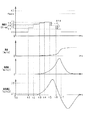
図4は、図3で示した一連の処理を繰り返し行った場合のタイムチャートである。図4では、車両制御装置が指令する駆動力、車輪側センサにより検出される速度、加速度センサ34により検出される加速度、その加速度を時間微分した値である加加速度を示している。図4において、速度の値は、車両10が段差61を越える方向への速度を正の値としている。すなわち、車両10が後退して段差61を乗り越えるのならば、その後退方向への速度を正の値としている。
FIG. 4 is a time chart when the series of processing shown in FIG. 3 is repeated. FIG. 4 shows the driving force commanded by the vehicle control device, the speed detected by the wheel side sensor, the acceleration detected by the acceleration sensor 34, and the jerk that is a value obtained by time-differentiating the acceleration. In FIG. 4, the speed value is a positive value in the direction in which the
図4では、時刻t0において、要求駆動力をf0として検知しており、駆動力を抑制する制御が行われている。駆動力を初期駆動力であるf1からf2へと増加させる時刻t1から、駆動力をf3からf4へと増加させる時刻である時刻t3よりも前の時点までが第1処理を実施する期間である。また、時刻t3から、駆動力をt5から初期駆動力であるt1へと減少させる時刻である時刻t5よりも前の時点までが、第2処理を実施する期間である。 In FIG. 4, at the time t0, the required driving force is detected as f0, and control for suppressing the driving force is performed. The period from the time t1 when the driving force is increased from the initial driving force f1 to f2 to the time point before the time t3 when the driving force is increased from f3 to f4 is the period for performing the first processing. . Further, the period from the time t3 to the time before the time t5, which is the time when the driving force is decreased from t5 to the initial driving force t1, is the period for performing the second process.
運転者によるアクセル操作により、アクセルセンサ32が要求駆動力をf0として検知しており、且つ、速度が0である状態が所定時間継続した時刻t1において、駆動力を初期駆動力であるf1からf2へと上昇させる制御を行う。駆動力をf2へと増加させた場合に加加速度は第1所定値であるj1以下であるため、時刻t1から所定時間が経過した時刻t2において、駆動力をf3へと増加させる。このとき、駆動力をf1からf2へと増加させた際の駆動力の増加量、及び、駆動力をf2からf3へと増加させた際の駆動力の増加量は、いずれもΔf1であり、等しい値である。 At time t1 when the accelerator sensor 32 detects the required driving force as f0 by the driver's accelerator operation and the state where the speed is 0 continues for a predetermined time, the driving force is changed from the initial driving force f1 to f2. Control to raise to. When the driving force is increased to f2, the jerk is equal to or less than the first predetermined value j1, so the driving force is increased to f3 at time t2 when a predetermined time has elapsed from time t1. At this time, the amount of increase in the driving force when the driving force is increased from f1 to f2 and the amount of increase in the driving force when the driving force is increased from f2 to f3 are both Δf1, It is an equal value.
続く時刻t3において、加加速度が第1所定値であるj1を超えているため、駆動力の増加量をΔf1よりも小さい値であるΔf2とし、駆動力をf4へと引き上げる。このとき、Δf2は、加加速度の値により得られる値である。さらに、時刻t4において、加加速度が第2所定値であるj2を超えていないため、駆動力の増加量をΔf2より小さい値であるΔf3とし、駆動力をf5へと引き上げる。このとき、駆動力が上限値であるfmaxに到達すれば駆動力はfmaxとされる。 At the subsequent time t3, since the jerk exceeds the first predetermined value j1, the increase amount of the driving force is set to Δf2, which is a value smaller than Δf1, and the driving force is raised to f4. At this time, Δf2 is a value obtained from the jerk value. Further, at time t4, since the jerk does not exceed the second predetermined value j2, the amount of increase in driving force is set to Δf3, which is a value smaller than Δf2, and the driving force is increased to f5. At this time, if the driving force reaches the upper limit value fmax, the driving force is set to fmax.
時刻t5において、駆動力が第2所定値を超えれば、駆動力を初期駆動力であるf1へと戻す処理を行う。このとき、段差61の乗り越えは終了しているため、速度は、その駆動力に対応した一定の値をとることとなる。なお、図示していないが、車両10と障害物との距離が停止距離となれば、運転者によるアクセル操作によらず、駆動力をゼロとする処理を行う。また、このときに運転者によるブレーキ操作が行われていなければ、制動制御を行う。
If the driving force exceeds the second predetermined value at time t5, processing for returning the driving force to the initial driving force f1 is performed. At this time, since the
上記構成により、本実施形態に係る車両制御装置は、以下の効果を奏する。 With the above configuration, the vehicle control device according to the present embodiment has the following effects.
・車両10が移動を開始した場合に駆動力の時間当たりの増加量を小さくすることで、車速が過剰なものとなることを抑制しつつ、段差61の乗り越えを可能とすることができる。加えて、車両10が移動を開始した場合に、ただちに駆動力の漸増を終了したり、駆動力を初期値へ戻したりせず、駆動力の漸増を行うものとしているため、段差61の乗り越え等に要する時間を短縮することができる。
-When the
・駆動力の時間当たりの増加量を加加速度の値に応じて変更しているため、車両10の段差61の乗り越えが終了した時点での駆動力が、過剰なものとなることをより抑制することができる。
Since the amount of increase in driving force per hour is changed according to the value of jerk, the driving force at the time when the step over the
・加速度により車両10の移動を判定する場合、坂路におけるオフセットの影響を受ける可能性がある。また、速度により車両10の移動を判定する場合、極定速では車両10の移動の開始の判定が困難である。この点、加加速度により車両10の移動開始を判定しているため、より精度よく車両10の移動開始を検出することができる。
-When determining the movement of the
<第2実施形態>
本実施形態では、加加速度が第2所定値を超えた場合の処理が第1実施形態と異なっている。具体的には、加加速度が第2所定値を超えれば、駆動力を漸減させる処理を行う。
Second Embodiment
In the present embodiment, the process when the jerk exceeds the second predetermined value is different from the first embodiment. Specifically, when the jerk exceeds the second predetermined value, processing for gradually reducing the driving force is performed.
図5は本実施形態に係る処理を行う場合の一連の制御を示すフローチャートである。なお、図5のフローチャートにおいて、第1実施形態と同等の処理については同じ符号を付与しており、その説明は省略する。 FIG. 5 is a flowchart showing a series of controls when the processing according to the present embodiment is performed. In the flowchart of FIG. 5, the same reference numerals are assigned to the same processes as those in the first embodiment, and the description thereof is omitted.
まず、第1実施形態と同様に、S104の処理までを行い、S104で増補正状態であると判定すれば、駆動力を漸減させる処理を行っているか否かを判定する(S201)。S201では、駆動力を漸減する処理が開始されたことを示すフラグにより、判定を行う。駆動力を漸減させる処理を行っていなければ(S201:NO)、第1実施形態と同様に、加加速度が第1所定値、第2所定値を超えたか否かを判定する(S107,S108)。加加速度が第2所定値を超えていれば(S108:YES)、駆動力を漸減する処理が開始されたこと示すフラグをONとする(S202)。そして、駆動力の漸減処理を行い(S202)、一連の処理を終了する。 First, similarly to the first embodiment, the processing up to S104 is performed, and if it is determined in S104 that it is in the increased correction state, it is determined whether or not the processing for gradually decreasing the driving force is performed (S201). In S201, a determination is made based on a flag indicating that the process of gradually reducing the driving force has started. If the process of gradually decreasing the driving force is not performed (S201: NO), it is determined whether or not the jerk exceeds the first predetermined value and the second predetermined value as in the first embodiment (S107, S108). . If the jerk exceeds the second predetermined value (S108: YES), the flag indicating that the process of gradually reducing the driving force has been started is set to ON (S202). Then, a gradual reduction process of the driving force is performed (S202), and a series of processes ends.
一方、駆動力を漸減させる処理が既に開始していれば(S201:YES)、駆動力の漸減処理を行い(S203)、一連の処理を終了する。なお、駆動力を漸減する処理が開始されたことを示すフラグについては、駆動力の漸減処理を行った結果として駆動力が初期駆動力となっていれば、リセットするものとすればよい。 On the other hand, if the process of gradually reducing the driving force has already started (S201: YES), the driving force is gradually reduced (S203), and the series of processes is terminated. Note that the flag indicating that the process of gradually reducing the driving force has been started may be reset if the driving force is the initial driving force as a result of performing the driving force gradually decreasing process.
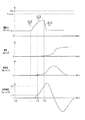
図6は、図5で示した一連の処理を繰り返し行った場合のタイムチャートである。なお、車両10が発進制限状態となり、駆動力を増加させる処理を継続する時刻t5よりも前までは、第1実施形態と同等であるため、その説明を省略する。時刻t5において、加加速度が第2所定値を超えれば、駆動力を漸減させる処理を開始する。
FIG. 6 is a time chart when the series of processing shown in FIG. 5 is repeated. Since the
時刻t5では、駆動力の減少量をΔf4とする。続く時刻t6でも駆動力の減少量をΔf4とする。そして、時刻t7では、そのときの駆動力と初期駆動力との乖離量がΔf4よりも小さいため、駆動力を初期駆動力とする。なお、駆動力の減量量については一定でなくてもよい。例えば、駆動力が大きいほど、減少量を大きくしてもよい。 At time t5, the amount of decrease in driving force is Δf4. At subsequent time t6, the amount of decrease in driving force is Δf4. At time t7, since the amount of deviation between the driving force and the initial driving force at that time is smaller than Δf4, the driving force is set as the initial driving force. Note that the amount of reduction in the driving force may not be constant. For example, the amount of decrease may be increased as the driving force increases.
上記構成により、本実施形態に係る車両制御装置は、第1実施形態に係る車両制御装置が奏する効果に加えて、以下の効果を奏する。 With the above configuration, the vehicle control apparatus according to the present embodiment has the following effects in addition to the effects exhibited by the vehicle control apparatus according to the first embodiment.
・駆動力が第2所定値を超えた場合に、駆動力をただちに初期駆動力とした場合、段差61を登りかけた状態で車両10が停止する可能性がある。本実施形態では、駆動力を漸減させているため、段差61を登りかけた状態で車両10が停止する事態を抑制することができる。
When the driving force exceeds the second predetermined value, if the driving force is immediately set as the initial driving force, the
<変形例>
・各実施形態では、段差61により発進制限状態となる例を示しているが、坂路においても、同様に発進制限状態となる。すなわち、段差61が存在する場合や坂路である場合等、走行抵抗が存在する場合に、初期駆動力では停止状態から発進することができないため、上記各実施形態に係る処理を同様に適用することができる。
<Modification>
-In each embodiment, although the example which becomes a start restriction state by the level |
・各実施形態では、駆動力を所定周期毎に段階的に増加させるものとしたが、図7で示すように、毎回の処理で増減を行うものとしてもよい。このとき、加加速度が第1所定値以下であれば、駆動力の時間当たりの増加量をdf1/dtとし、加加速度が第1所定値よりも大きく第2所定値以下であれば、駆動力の時間当たりの増加量をdf1/dtよりも小さい値であるdf2/dtとする。このdf2/dtの値は、加加速度が大きくなるほど、小さくなる値である。そして、加加速度が第2所定値を超えれば、駆動力の時間当たりの減少量をdf3/dt(<0)とする。なお、第1実施形態のごとく、加加速度が第2所定値を超えれば、駆動力を初期駆動力とする制御を行うものとしてもよい。 In each embodiment, the driving force is increased step by step for each predetermined period. However, as shown in FIG. 7, the driving force may be increased or decreased each time. At this time, if the jerk is equal to or less than the first predetermined value, the increase amount of the driving force per time is df1 / dt, and if the jerk is larger than the first predetermined value and equal to or smaller than the second predetermined value, the driving force Is increased to df2 / dt which is smaller than df1 / dt. The value of df2 / dt is a value that decreases as the jerk increases. If the jerk exceeds the second predetermined value, the amount of decrease in driving force per time is set to df3 / dt (<0). Note that, as in the first embodiment, if the jerk exceeds the second predetermined value, control using the driving force as the initial driving force may be performed.
・第1実施形態において、第2実施形態のごとく、加加速度が第1所定値を超えれば、第1所定値を超えたことを示すフラグを立て、次回以降の制御において、S107の処理を行わず、S108以降の処理を行うものとしてもよい。加加速度が第2所定値を超えた場合についても同様である。 In the first embodiment, as in the second embodiment, if the jerk exceeds the first predetermined value, a flag indicating that the first predetermined value has been exceeded is set, and the process of S107 is performed in the subsequent control. Instead, the processing after S108 may be performed. The same applies to the case where the jerk exceeds the second predetermined value.
・各実施形態において、駆動力が第1所定値を超えた場合における駆動力の増加量を、加加速度の値に応じて決定するものとしたが、駆動力の増加量を等しいものとしてもよい。こうすることにより、制御の簡略化が可能となる。 In each embodiment, the amount of increase in driving force when the driving force exceeds the first predetermined value is determined according to the jerk value, but the amount of increase in driving force may be equal. . By doing so, the control can be simplified.
・各実施形態において、加加速度の値により、車両10が移動を開始したか否かを判定するものとしたが、速度又は加速度の値により車両10が移動を開始したか否かを判定するものとしてもよい。なお、加速度の値を判定に用いる場合、車両10が停止した状態での値をオフセットとし、その値からの変化量が閾値を超えたか否かを判定するものとすればよい。
In each embodiment, whether or not the
・各実施形態において、加加速度の値により、車両10が移動を開始したか否かを判定するものとしたが、速度、加速度及び加加速度の2つ以上の値を用いて車両10が移動を開始したか否かを判定するものとしてもよい。例えば、加加速度の値が閾値を超えずに段差61を乗り越えた場合には、速度の値は駆動力の値に応じたものとる。この場合には、車輪速センサ31により車両10の移動を検知することができるため、速度により段差61の乗り越えを判定する処理を追加してもよい。
In each embodiment, it is determined whether or not the
・上記実施形態では、発進制限状態であるか否かを(a)〜(d)のすべての条件が満たされたとしているが、発進制限状態であるか否かを、少なくとも(a)及び(b)の条件を満たす場合に、発進制限状態であると判定してもよい。 In the above embodiment, it is assumed that all the conditions (a) to (d) are satisfied as to whether or not the vehicle is in the start restricted state, but at least (a) and ( When the condition of b) is satisfied, it may be determined that the vehicle is in a start restriction state.
・上記実施形態において、アクセルセンサ32の検出値に基づいて発進制限状態を判定しているが、上位のECUからの指令により自動的に運転を行う車両10に適用し、その指令に基づく駆動力が壁50との距離により抑制されており、且つ、車両10が発進制限である状態において、駆動力を増加させる制御を行うものとしてもよい。
In the above embodiment, the start restriction state is determined based on the detection value of the accelerator sensor 32. However, it is applied to the
・上記実施形態では、加速度センサ34により検出された加速度を時間微分することにより加加速度の値を得ているが、加加速度の値を直接検出する加加速度センサを用いてもよい。 In the above embodiment, the jerk value is obtained by time differentiation of the acceleration detected by the acceleration sensor 34. However, a jerk sensor that directly detects the jerk value may be used.
・上記実施形態では、駆動力としてトルクを例示しているが、出力を制御するものとしてもよい。また、エンジン41の回転数を制御するものとしてもよい。 In the above embodiment, torque is exemplified as the driving force, but the output may be controlled. Further, the rotational speed of the engine 41 may be controlled.
・上記実施形態では、車両10の駆動源をエンジン41としたが、車両10をモータにより駆動し、そのモータの駆動力の制御を行うものとしてもよい。
In the above embodiment, the drive source of the
10…車両、21…物体検出部、22…状態取得部、23…抑制部、34…加速度センサ。
DESCRIPTION OF
Claims (11)
前記物体検出部が前記物体を検出した場合に、前記車両の駆動力を抑制する抑制部(23)と、を備え、
前記抑制部は、前記車両の駆動力を抑制している状態で、前記進行方向への移動の指示が行われ、且つ前記車両が停止している場合に、前記駆動力を漸増させる第1処理を行い、前記車両が停止状態から移動を開始した後は、前記駆動力の時間当たりの増加量を第1処理よりも小さくして漸増させる第2処理を行い、
車両の進行方向への速度の値、車両の進行方向への加速度の値、及び進行方向への加加速度の値の少なくともひとつを判定値として取得する状態取得部(12)をさらに備え、
前記抑制部は、前記判定値に基づいて移動を開始したと判定し、前記第2処理を行い、前記第2処理では、前記判定値が大きいほど前記駆動力の時間当たりの増加量を小さくする、車両制御装置(20)。 An object detection unit (21) for detecting an object in the traveling direction of the vehicle (10);
A suppression unit (23) for suppressing the driving force of the vehicle when the object detection unit detects the object,
The suppression unit gradually increases the driving force when an instruction to move in the traveling direction is given while the driving force of the vehicle is suppressed and the vehicle is stopped. was carried out, after the vehicle starts to move from the stopped state, have rows second process gradually increasing to less than the first handle the increased amount per unit time of the driving force,
A state acquisition unit (12) for acquiring at least one of a speed value in the traveling direction of the vehicle, a value of acceleration in the traveling direction of the vehicle, and a value of jerk in the traveling direction as a determination value;
The suppression unit determines that movement has started based on the determination value, and performs the second process. In the second process, the larger the determination value, the smaller the increase amount of the driving force per time. The vehicle control device (20).
車両の進行方向への速度の値、車両の進行方向への加速度の値、及び進行方向への加加速度の値の少なくともひとつを判定値として取得する状態取得部(22)と、
前記物体検出部が物体を検出した場合に、前記車両の駆動力を抑制する抑制部(23)と、を備え、
前記抑制部は、前記車両の駆動力を抑制している状態で、前記進行方向への移動の指示が行われた場合に、前記判定値が閾値よりも小さければ、前記駆動力を漸増させる増加処理を行い、
前記増加処理では、前記判定値が大きいほど、前記駆動力の時間当たりの増加量を小さくする、車両制御装置(20)。 An object detection unit (21) for detecting an object in the traveling direction of the vehicle (10);
A state acquisition unit (22) for acquiring at least one of a speed value in the traveling direction of the vehicle, a value of acceleration in the traveling direction of the vehicle, and a value of jerk in the traveling direction as a determination value;
A suppression unit (23) that suppresses the driving force of the vehicle when the object detection unit detects an object, and
The suppression unit gradually increases the driving force if the determination value is smaller than a threshold when an instruction to move in the traveling direction is given in a state where the driving force of the vehicle is suppressed. Process,
In the increasing process, the vehicle control device (20) reduces the amount of increase in the driving force per time as the determination value increases.
前記状態取得部は、前記加速度センサが検出した前記車両の進行方向への加速度に基づいて、前記加加速度を求め、その加加速度を前記判定値とする、請求項1〜6のいずれか1項に記載の車両制御装置。 The vehicle is provided with an acceleration sensor (34),
Wherein the state acquisition section, based on the acceleration in the traveling direction of the vehicle in which the acceleration sensor detects, the calculated jerk, the jerk and the decision value, any one of claims 1 to 6, The vehicle control device described in 1.
前記物体検出部が前記物体を検出した場合に、前記車両の駆動力を抑制する抑制部(23)と、を備え、
前記抑制部は、前記車両の駆動力を抑制している状態で、前記進行方向への移動の指示が行われ、且つ前記車両が停止している場合に、前記駆動力を漸増させる第1処理を行い、前記車両が停止状態から移動を開始した後は、前記駆動力の時間当たりの増加量を第1処理よりも小さくして漸増させる第2処理を行い、
車両の進行方向への速度の値、車両の進行方向への加速度の値、及び進行方向への加加速度の値の少なくともひとつを判定値として取得する状態取得部(12)をさらに備え、
前記抑制部は、前記判定値に基づいて移動を開始したと判定し、前記第2処理を行い、
前記車両には加速度センサ(34)が設けられており、
前記状態取得部は、前記加速度センサが検出した前記車両の進行方向への加速度に基づいて、前記加加速度を求め、その加加速度を前記判定値とする、車両制御装置(20)。 An object detection unit (21) for detecting an object in the traveling direction of the vehicle (10);
A suppression unit (23) for suppressing the driving force of the vehicle when the object detection unit detects the object,
The suppression unit gradually increases the driving force when an instruction to move in the traveling direction is given while the driving force of the vehicle is suppressed and the vehicle is stopped. After the vehicle starts moving from a stopped state, a second process is performed to gradually increase the driving force per time by making the increase amount smaller than the first process,
A state acquisition unit (12) for acquiring at least one of a speed value in the traveling direction of the vehicle, a value of acceleration in the traveling direction of the vehicle, and a value of jerk in the traveling direction as a determination value;
The suppression unit determines that movement has started based on the determination value, performs the second process,
The vehicle is provided with an acceleration sensor (34),
The vehicle control device (20) , wherein the state acquisition unit obtains the jerk based on the acceleration in the traveling direction of the vehicle detected by the acceleration sensor, and uses the jerk as the determination value .
前記車両の進行方向の物体を検出する物体検出ステップと、
車両の進行方向への速度の値、車両の進行方向への加速度の値、及び進行方向への加加速度の値の少なくともひとつを判定値として取得する状態取得ステップと、
前記物体検出ステップで物体を検出した場合に、前記車両の駆動力を抑制する抑制ステップと、を実行し、
前記抑制ステップでは、前記車両の駆動力を抑制している状態で、前記進行方向への移動の指示が行われた場合に、前記判定値が閾値よりも小さければ、前記駆動力を漸増させる増加処理を行い、
前記増加処理では、前記判定値が大きいほど、前記駆動力の時間当たりの増加量を小さくする、車両制御方法。 A vehicle control method executed by a vehicle control device (20) mounted on a vehicle (10),
An object detection step for detecting an object in the traveling direction of the vehicle;
A state acquisition step of acquiring at least one of a speed value in the traveling direction of the vehicle, an acceleration value in the traveling direction of the vehicle, and a jerk value in the traveling direction as a determination value;
A step of suppressing the driving force of the vehicle when an object is detected in the object detection step, and
In the suppression step, in the state where the driving force of the vehicle is suppressed, if an instruction to move in the traveling direction is given, if the determination value is smaller than a threshold value, the driving force is gradually increased. Process,
The vehicle control method, wherein in the increase process, the increase amount of the driving force per time is reduced as the determination value is increased.
Priority Applications (5)
| Application Number | Priority Date | Filing Date | Title |
|---|---|---|---|
| JP2015131129A JP6335848B2 (en) | 2015-06-30 | 2015-06-30 | Vehicle control apparatus and vehicle control method |
| CN201680038247.XA CN107835768B (en) | 2015-06-30 | 2016-06-21 | Vehicle control device and vehicle control method |
| DE112016003021.5T DE112016003021B4 (en) | 2015-06-30 | 2016-06-21 | Vehicle control device and vehicle control method |
| US15/740,551 US11465615B2 (en) | 2015-06-30 | 2016-06-21 | Vehicle control apparatus and vehicle control method |
| PCT/JP2016/068375 WO2017002668A1 (en) | 2015-06-30 | 2016-06-21 | Vehicle control device, and vehicle control method |
Applications Claiming Priority (1)
| Application Number | Priority Date | Filing Date | Title |
|---|---|---|---|
| JP2015131129A JP6335848B2 (en) | 2015-06-30 | 2015-06-30 | Vehicle control apparatus and vehicle control method |
Publications (3)
| Publication Number | Publication Date |
|---|---|
| JP2017013597A JP2017013597A (en) | 2017-01-19 |
| JP2017013597A5 JP2017013597A5 (en) | 2017-07-27 |
| JP6335848B2 true JP6335848B2 (en) | 2018-05-30 |
Family
ID=57608640
Family Applications (1)
| Application Number | Title | Priority Date | Filing Date |
|---|---|---|---|
| JP2015131129A Active JP6335848B2 (en) | 2015-06-30 | 2015-06-30 | Vehicle control apparatus and vehicle control method |
Country Status (5)
| Country | Link |
|---|---|
| US (1) | US11465615B2 (en) |
| JP (1) | JP6335848B2 (en) |
| CN (1) | CN107835768B (en) |
| DE (1) | DE112016003021B4 (en) |
| WO (1) | WO2017002668A1 (en) |
Families Citing this family (1)
| Publication number | Priority date | Publication date | Assignee | Title |
|---|---|---|---|---|
| JP7091816B2 (en) * | 2018-05-08 | 2022-06-28 | トヨタ自動車株式会社 | Driving force control device |
Family Cites Families (10)
| Publication number | Priority date | Publication date | Assignee | Title |
|---|---|---|---|---|
| JP2006297993A (en) * | 2005-04-15 | 2006-11-02 | Toyota Motor Corp | Driving force controller |
| JP4867561B2 (en) * | 2005-12-22 | 2012-02-01 | 日産自動車株式会社 | VEHICLE DRIVE OPERATION ASSISTANCE DEVICE AND VEHICLE WITH VEHICLE DRIVE OPERATION ASSISTANCE DEVICE |
| US7894971B2 (en) * | 2005-12-28 | 2011-02-22 | Toyota Jidosha Kabushiki Kaisha | Vehicle control apparatus |
| JP4446978B2 (en) * | 2006-04-28 | 2010-04-07 | トヨタ自動車株式会社 | Vehicle driving force control device |
| JP2008174102A (en) * | 2007-01-18 | 2008-07-31 | Toyota Motor Corp | Parking support system |
| JP2012210916A (en) * | 2011-03-23 | 2012-11-01 | Nissan Motor Co Ltd | Device and method for controlling braking and driving force of vehicle |
| JP2012219795A (en) * | 2011-04-14 | 2012-11-12 | Toyota Motor Corp | Vehicle and control method of the same |
| JP5874603B2 (en) * | 2012-10-31 | 2016-03-02 | トヨタ自動車株式会社 | Driving assistance device |
| EP3006294A4 (en) * | 2013-05-31 | 2017-02-22 | Hitachi Automotive Systems, Ltd. | Vehicle control device |
| JP6502662B2 (en) | 2014-12-24 | 2019-04-17 | 株式会社デンソー | Vehicle control device |
-
2015
- 2015-06-30 JP JP2015131129A patent/JP6335848B2/en active Active
-
2016
- 2016-06-21 CN CN201680038247.XA patent/CN107835768B/en active Active
- 2016-06-21 US US15/740,551 patent/US11465615B2/en active Active
- 2016-06-21 DE DE112016003021.5T patent/DE112016003021B4/en active Active
- 2016-06-21 WO PCT/JP2016/068375 patent/WO2017002668A1/en active Application Filing
Also Published As
| Publication number | Publication date |
|---|---|
| US20180201259A1 (en) | 2018-07-19 |
| CN107835768A (en) | 2018-03-23 |
| CN107835768B (en) | 2020-06-16 |
| JP2017013597A (en) | 2017-01-19 |
| US11465615B2 (en) | 2022-10-11 |
| WO2017002668A1 (en) | 2017-01-05 |
| DE112016003021T5 (en) | 2018-03-15 |
| DE112016003021B4 (en) | 2023-04-20 |
Similar Documents
| Publication | Publication Date | Title |
|---|---|---|
| JP6502662B2 (en) | Vehicle control device | |
| US11415995B2 (en) | Control device for vehicle and control method of vehicle | |
| JP6670901B2 (en) | Method and apparatus for assisting driving of a vehicle | |
| CN109591813B (en) | Collision avoidance assistance device | |
| US9896095B2 (en) | Collision avoidance support device | |
| JP6011489B2 (en) | In-vehicle control device | |
| EP3141461A1 (en) | Driving support device | |
| US11001255B2 (en) | Driving assistance apparatus and driving assistance method | |
| JP6155963B2 (en) | Collision mitigation device | |
| CN110654377A (en) | Vehicle anti-collision control method and control system | |
| JP7226348B2 (en) | Driving support device | |
| US11691621B2 (en) | Driving support apparatus including collision avoidance braking control | |
| EP2916306B1 (en) | Collision avoidance assist device and collision avoidance assist method | |
| JP2022125580A (en) | Collison avoidance support device | |
| US20180154890A1 (en) | Vehicle control device and vehicle control method | |
| CN113104008A (en) | Driving support device | |
| CN109070852B (en) | Emergency braking system for a vehicle and method for controlling an emergency braking system | |
| JP6335848B2 (en) | Vehicle control apparatus and vehicle control method | |
| JP2024034044A (en) | Driving support device, driving support method, and driving support program | |
| JP5512852B1 (en) | Driving assistance device | |
| CN116279342A (en) | Anti-collision auxiliary device |
Legal Events
| Date | Code | Title | Description |
|---|---|---|---|
| A521 | Request for written amendment filed |
Free format text: JAPANESE INTERMEDIATE CODE: A523 Effective date: 20170615 |
|
| A621 | Written request for application examination |
Free format text: JAPANESE INTERMEDIATE CODE: A621 Effective date: 20170615 |
|
| TRDD | Decision of grant or rejection written | ||
| A01 | Written decision to grant a patent or to grant a registration (utility model) |
Free format text: JAPANESE INTERMEDIATE CODE: A01 Effective date: 20180403 |
|
| A61 | First payment of annual fees (during grant procedure) |
Free format text: JAPANESE INTERMEDIATE CODE: A61 Effective date: 20180501 |
|
| R150 | Certificate of patent or registration of utility model |
Ref document number: 6335848 Country of ref document: JP Free format text: JAPANESE INTERMEDIATE CODE: R150 |
|
| R250 | Receipt of annual fees |
Free format text: JAPANESE INTERMEDIATE CODE: R250 |
|
| R250 | Receipt of annual fees |
Free format text: JAPANESE INTERMEDIATE CODE: R250 |
|
| R250 | Receipt of annual fees |
Free format text: JAPANESE INTERMEDIATE CODE: R250 |