JP6332020B2 - Recording head recovery system and ink jet recording apparatus including the same - Google Patents
Recording head recovery system and ink jet recording apparatus including the same Download PDFInfo
- Publication number
- JP6332020B2 JP6332020B2 JP2014263990A JP2014263990A JP6332020B2 JP 6332020 B2 JP6332020 B2 JP 6332020B2 JP 2014263990 A JP2014263990 A JP 2014263990A JP 2014263990 A JP2014263990 A JP 2014263990A JP 6332020 B2 JP6332020 B2 JP 6332020B2
- Authority
- JP
- Japan
- Prior art keywords
- ink
- wiping
- wiper
- nozzle
- end portion
- Prior art date
- Legal status (The legal status is an assumption and is not a legal conclusion. Google has not performed a legal analysis and makes no representation as to the accuracy of the status listed.)
- Active
Links
Images


Classifications
-
- B—PERFORMING OPERATIONS; TRANSPORTING
- B41—PRINTING; LINING MACHINES; TYPEWRITERS; STAMPS
- B41J—TYPEWRITERS; SELECTIVE PRINTING MECHANISMS, i.e. MECHANISMS PRINTING OTHERWISE THAN FROM A FORME; CORRECTION OF TYPOGRAPHICAL ERRORS
- B41J2/00—Typewriters or selective printing mechanisms characterised by the printing or marking process for which they are designed
- B41J2/005—Typewriters or selective printing mechanisms characterised by the printing or marking process for which they are designed characterised by bringing liquid or particles selectively into contact with a printing material
- B41J2/01—Ink jet
- B41J2/135—Nozzles
- B41J2/165—Preventing or detecting of nozzle clogging, e.g. cleaning, capping or moistening for nozzles
- B41J2/16517—Cleaning of print head nozzles
- B41J2/16535—Cleaning of print head nozzles using wiping constructions
-
- B—PERFORMING OPERATIONS; TRANSPORTING
- B41—PRINTING; LINING MACHINES; TYPEWRITERS; STAMPS
- B41J—TYPEWRITERS; SELECTIVE PRINTING MECHANISMS, i.e. MECHANISMS PRINTING OTHERWISE THAN FROM A FORME; CORRECTION OF TYPOGRAPHICAL ERRORS
- B41J2/00—Typewriters or selective printing mechanisms characterised by the printing or marking process for which they are designed
- B41J2/005—Typewriters or selective printing mechanisms characterised by the printing or marking process for which they are designed characterised by bringing liquid or particles selectively into contact with a printing material
- B41J2/01—Ink jet
- B41J2/135—Nozzles
- B41J2/165—Preventing or detecting of nozzle clogging, e.g. cleaning, capping or moistening for nozzles
- B41J2/16505—Caps, spittoons or covers for cleaning or preventing drying out
- B41J2/16508—Caps, spittoons or covers for cleaning or preventing drying out connected with the printer frame
- B41J2/16511—Constructions for cap positioning
-
- B—PERFORMING OPERATIONS; TRANSPORTING
- B41—PRINTING; LINING MACHINES; TYPEWRITERS; STAMPS
- B41J—TYPEWRITERS; SELECTIVE PRINTING MECHANISMS, i.e. MECHANISMS PRINTING OTHERWISE THAN FROM A FORME; CORRECTION OF TYPOGRAPHICAL ERRORS
- B41J2/00—Typewriters or selective printing mechanisms characterised by the printing or marking process for which they are designed
- B41J2/005—Typewriters or selective printing mechanisms characterised by the printing or marking process for which they are designed characterised by bringing liquid or particles selectively into contact with a printing material
- B41J2/01—Ink jet
- B41J2/135—Nozzles
- B41J2/165—Preventing or detecting of nozzle clogging, e.g. cleaning, capping or moistening for nozzles
- B41J2/16517—Cleaning of print head nozzles
- B41J2/16535—Cleaning of print head nozzles using wiping constructions
- B41J2/16538—Cleaning of print head nozzles using wiping constructions with brushes or wiper blades perpendicular to the nozzle plate
-
- B—PERFORMING OPERATIONS; TRANSPORTING
- B41—PRINTING; LINING MACHINES; TYPEWRITERS; STAMPS
- B41J—TYPEWRITERS; SELECTIVE PRINTING MECHANISMS, i.e. MECHANISMS PRINTING OTHERWISE THAN FROM A FORME; CORRECTION OF TYPOGRAPHICAL ERRORS
- B41J2/00—Typewriters or selective printing mechanisms characterised by the printing or marking process for which they are designed
- B41J2/005—Typewriters or selective printing mechanisms characterised by the printing or marking process for which they are designed characterised by bringing liquid or particles selectively into contact with a printing material
- B41J2/01—Ink jet
- B41J2/135—Nozzles
- B41J2/165—Preventing or detecting of nozzle clogging, e.g. cleaning, capping or moistening for nozzles
- B41J2/16517—Cleaning of print head nozzles
- B41J2/16535—Cleaning of print head nozzles using wiping constructions
- B41J2/16544—Constructions for the positioning of wipers
-
- B—PERFORMING OPERATIONS; TRANSPORTING
- B41—PRINTING; LINING MACHINES; TYPEWRITERS; STAMPS
- B41J—TYPEWRITERS; SELECTIVE PRINTING MECHANISMS, i.e. MECHANISMS PRINTING OTHERWISE THAN FROM A FORME; CORRECTION OF TYPOGRAPHICAL ERRORS
- B41J2/00—Typewriters or selective printing mechanisms characterised by the printing or marking process for which they are designed
- B41J2/005—Typewriters or selective printing mechanisms characterised by the printing or marking process for which they are designed characterised by bringing liquid or particles selectively into contact with a printing material
- B41J2/01—Ink jet
- B41J2/135—Nozzles
- B41J2/165—Preventing or detecting of nozzle clogging, e.g. cleaning, capping or moistening for nozzles
- B41J2/16585—Preventing or detecting of nozzle clogging, e.g. cleaning, capping or moistening for nozzles for paper-width or non-reciprocating print heads
- B41J2002/16591—Preventing or detecting of nozzle clogging, e.g. cleaning, capping or moistening for nozzles for paper-width or non-reciprocating print heads for line print heads above an endless belt
Description
本発明は、用紙のような記録媒体にインクを吐出することによって記録を行うインクジェット記録装置に関し、特に、記録ヘッドの吐出ノズルからインクを強制的に押出した後、インク吐出面に付着したパージインクをワイパーで拭き取る記録ヘッドの回復システム及びそれを備えたインクジェット記録装置に関するものである。 The present invention relates to an inkjet recording apparatus that performs recording by ejecting ink onto a recording medium such as paper, and in particular, purge ink that adheres to an ink ejection surface after forcibly ejecting ink from ejection nozzles of a recording head. The present invention relates to a recording head recovery system for wiping off a recording medium with a wiper and an ink jet recording apparatus including the recovery system.
ファクシミリ、複写機、プリンターのような記録装置として、インクを吐出して画像を形成するインクジェット記録装置が、高精細な画像を形成できることから広く用いられている。 2. Description of the Related Art As a recording apparatus such as a facsimile, a copying machine, and a printer, an ink jet recording apparatus that forms an image by ejecting ink is widely used because it can form a high-definition image.
このようなインクジェット記録装置では、インクの直進性の悪化(飛翔曲がり)や不吐出等が発生して記録ヘッドの印字性能が低下することがある。この原因としては、用紙(記録媒体)の搬送時に発生する紙粉や埃、塵のような異物や、画像記録のためのインク滴と共に吐出される微小なインク滴(以下、ミストと称する)や、インク滴が記録媒体に付着した際に発生する跳ね返りミストが、記録ヘッドのインク吐出面に付着することによるメニスカス異常の発生が考えられる。また、キャップ装着箇所へミストが付着して乾燥することによるキャップ装着時の密閉性の低下、及びそれに伴うノズル内のインクの粘度上昇の発生も考えられる。 In such an ink jet recording apparatus, there is a case where the straight performance of the ink is deteriorated (flying bending), non-ejection, etc., and the printing performance of the recording head is deteriorated. This may be caused by foreign matters such as paper dust, dust, and dust generated during conveyance of the paper (recording medium), minute ink droplets (hereinafter referred to as mist) ejected together with ink droplets for image recording, The occurrence of meniscus abnormality due to the rebound mist generated when the ink droplets adhere to the recording medium adhere to the ink discharge surface of the recording head can be considered. Further, it is conceivable that the sealing performance is lowered when the cap is attached due to the mist adhering to the place where the cap is attached and drying, and the viscosity of the ink in the nozzle is increased accordingly.
そこで、記録ヘッドのインク吐出面に開口が設けられた吐出ノズル内のインクの乾燥や、吐出ノズル内のインクの増粘によるノズルの目詰まりを防止するために、ノズルからインクを強制的に押出(パージ)した後、インク吐出面(ノズル面)に付着したパージインクをワイパーで拭き取って記録ヘッドの回復処理を行う構成が用いられている。 Therefore, in order to prevent ink from being dried in the discharge nozzles with openings on the ink discharge surface of the recording head and clogging of the nozzles due to thickening of the ink in the discharge nozzles, the ink is forced out of the nozzles. A configuration is used in which, after (purging), the purge ink adhering to the ink ejection surface (nozzle surface) is wiped with a wiper to perform a recovery process of the recording head.
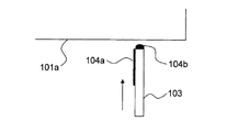
例えば、記録ヘッドのインク吐出面のノズルのない部分にワイパーを所定の接触圧で接触させてインク吐出面を拭き取る方法が知られている。具体的には、図35Aのように、記録ヘッド101のインク吐出面101aの、吐出ノズルの配置されたノズル領域102の外側の領域(拭き取り開始位置)にワイパー103を略垂直に押し当てる。次に、図35B、図35Cのようにワイパー103をインク吐出面101aに沿って矢印A方向に水平移動させることでノズル領域102のインク104を拭き取り、図35Dのようにワイパー103をインク吐出面101aから離間させた後、矢印A′方向に水平移動させることで拭き取り開始位置まで戻す。
For example, a method of wiping the ink discharge surface by bringing a wiper into contact with a portion of the ink discharge surface of the recording head without a nozzle at a predetermined contact pressure is known. Specifically, as shown in FIG. 35A, the
しかし、図35A〜図35Dに示す方法では、図36Aに示すように、2回目の拭き取り時にはワイパー103の側面および先端にインク104a、104bが付着している。ワイパー103の側面および先端に付着したインク104a、104bは空気に触れて増粘しており、図36Bおよび図36Cのように、インク吐出面101aに付着する。
However, in the method shown in FIGS. 35A to 35D, as shown in FIG. 36A, the
上記のように拭き取り動作を繰り返すことで、拭き取り開始位置近傍に徐々にインク104bが溜まり、大きなインク溜まりとなる。このインク溜まりがインク吐出面101aの下方を通過する記録媒体上に落下したり、接触したりして印字面を汚してしまうという不都合があった。
By repeating the wiping operation as described above, the
この不都合を改善するために、特許文献1には、記録ヘッドのインク吐出面に順次接触可能な2枚のワイパーを有し、先行するワイパーによってパージインクを拭き取り、後続のワイパーによって先行するワイパーの拭き取り開始位置近傍に残るインクを拭き取るようにしたインクジェット記録装置のワイピング機構が開示されている。 In order to improve this inconvenience, Patent Document 1 has two wipers that can sequentially contact the ink discharge surface of the recording head, wipe the purge ink with the preceding wiper, and remove the preceding wiper with the subsequent wiper. A wiping mechanism of an ink jet recording apparatus is disclosed in which ink remaining in the vicinity of the wiping start position is wiped off.
しかしながら、特許文献1の構造では、後続のワイパーが拭き取ったインクが、次回の拭き取り時に、後続のワイパーの拭き取り開始位置に付着する。そして、拭き取り動作を繰り返すことによって、大きなインク溜まりが形成されるという問題点がある。また、このワイピング機構では、ワイパーの数が多くなるので構造が複雑になるという問題点もある。 However, in the structure of Patent Document 1, the ink wiped by the subsequent wiper adheres to the wiping start position of the subsequent wiper at the next wiping. There is a problem that a large ink reservoir is formed by repeating the wiping operation. In addition, this wiping mechanism has a problem that the structure becomes complicated because the number of wipers increases.
本発明は、上記のような課題を解決するためになされたものであり、本発明の目的は、簡易な構成で、インク吐出面におけるインク溜まりの発生を抑制することが可能な記録ヘッドの回復システム及びそれを備えたインクジェット記録装置を提供することである。 The present invention has been made to solve the above-described problems, and an object of the present invention is to recover a recording head that can suppress the occurrence of ink accumulation on the ink ejection surface with a simple configuration. A system and an inkjet recording apparatus including the system are provided.
上記目的を達成するために、本発明の記録ヘッドの回復システムは、記録媒体上にインクを吐出する吐出ノズルが開口するノズル領域が設けられた記録ヘッドの回復システムであって、吐出ノズルから強制的に押出されたパージインクを拭き取るワイパーと、ワイパーを、ノズル領域を含むインク吐出面に沿って往復移動させる駆動機構と、吐出ノズルからのインクの押し出し及び吐出、並びに駆動機構の動作を制御する制御部と、を備える。制御部は、吐出ノズルからインクを強制的に押出してノズル領域にパージインクを付着させる第1インク押出動作と、インク吐出面におけるノズル領域の外側の第1位置にワイパーを圧接させた後、ワイパーをインク吐出面に圧接させた状態でインク吐出面に沿ってノズル領域側に向かう第1方向に移動させることにより、パージインクを拭き取り、ノズル領域に対して第1位置とは反対側の第2位置までワイパーを移動させる第1拭き取り動作と、ノズル領域に対して第1位置とは反対側の位置からノズル領域に対して第1位置側の位置まで、ワイパーをインク吐出面に圧接させた状態でインク吐出面に沿って移動させる第2拭き取り動作と、を含む記録ヘッドの回復動作を実行可能である。ワイパーは、第1方向に向かって配置される第1拭き取り面と、第1方向とは反対の第2方向に向かって配置される第2拭き取り面と、第1拭き取り面および第2拭き取り面の間に配置される上面と、を含み、第1拭き取り面は、第1拭き取り動作においてワイパーが第1方向に移動する際にインク吐出面に接触する第1上端部を含み、第2拭き取り面は、第2拭き取り動作においてワイパーが第2方向に移動する際にインク吐出面に接触する第2上端部を含み、上面には、第1上端部と第2上端部との間に側面視矩形状の凸部が形成されており、第1上端部と凸部との間に第1上端部側から第2上端部側に向かって高くなる第1段差部が形成されている。 In order to achieve the above object, a recording head recovery system of the present invention is a recording head recovery system in which a nozzle region in which an ejection nozzle for ejecting ink is provided on a recording medium is provided. A wiper that wipes out the purged ink that has been pushed out, a drive mechanism that reciprocates the wiper along the ink ejection surface including the nozzle region, and extrusion and ejection of ink from the ejection nozzle, as well as controlling the operation of the drive mechanism. A control unit. The control unit includes a first ink pushing operation for forcibly pushing the ink from the discharge nozzle to attach the purge ink to the nozzle region, and after pressing the wiper to the first position outside the nozzle region on the ink discharge surface, Is moved in the first direction toward the nozzle region along the ink discharge surface in a state where the ink is in pressure contact with the ink discharge surface, thereby wiping the purge ink to remove the second ink on the side opposite to the first position with respect to the nozzle region. A first wiping operation for moving the wiper to a position, and a state in which the wiper is pressed against the ink ejection surface from a position opposite to the first position with respect to the nozzle area to a position on the first position with respect to the nozzle area. And a second wiping operation for moving the ink along the ink ejection surface. The wiper includes: a first wiping surface disposed toward the first direction; a second wiping surface disposed toward the second direction opposite to the first direction; and the first wiping surface and the second wiping surface. The first wiping surface includes a first upper end portion that contacts the ink ejection surface when the wiper moves in the first direction in the first wiping operation, and the second wiping surface is And a second upper end portion that comes into contact with the ink ejection surface when the wiper moves in the second direction in the second wiping operation, and the upper surface has a rectangular shape in side view between the first upper end portion and the second upper end portion. The first step portion is formed between the first upper end portion and the convex portion so as to increase from the first upper end portion side toward the second upper end portion side.
本発明によれば、インク吐出面に残留インクが溜まるのを抑制することができるので、大きなインク溜まりが発生するのを抑制することができる。また、記録ヘッドの回復システムの構造が複雑になるのを抑制することができる。 According to the present invention, it is possible to suppress the residual ink from collecting on the ink discharge surface, and thus it is possible to suppress the occurrence of a large ink pool. Further, it is possible to prevent the structure of the recording head recovery system from becoming complicated.
以下、本発明の実施形態について図面を参照して説明する。 Embodiments of the present invention will be described below with reference to the drawings.
(第1実施形態)
図1に示すように、本発明の第1実施形態のインクジェット記録装置100の左側部には用紙S(記録媒体)を収容する給紙トレイ2が設けられており、この給紙トレイ2の一端部には収容された用紙Sを、最上位の用紙Sから順に一枚ずつ後述する第1搬送ユニット5へと給紙するための給紙ローラー3と、給紙ローラー3に圧接され従動回転する従動ローラー4とが設けられている。
(First embodiment)
As shown in FIG. 1, a
用紙搬送方向(矢印X方向)に対し給紙ローラー3及び従動ローラー4の下流側(図1の右側)には、第1搬送ユニット5及び記録部9が配置されている。第1搬送ユニット5は、第1駆動ローラー6と、第1従動ローラー7と、第1駆動ローラー6及び第1従動ローラー7に掛け渡された第1搬送ベルト8とを含む構成であり、インクジェット記録装置100の制御部110からの制御信号により第1駆動ローラー6が時計回り方向に回転駆動されることにより、第1搬送ベルト8に保持された用紙Sが矢印X方向に搬送される。
A
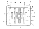
記録部9は、ヘッドハウジング10と、ヘッドハウジング10に保持されたラインヘッド11C、11M、11Y、及び11Kを備えている。これらのラインヘッド11C〜11Kは、第1搬送ベルト8の搬送面に対して所定の間隔(例えば1mm)が形成されるような高さに支持され、図2および図3に示すように、用紙搬送方向と直交する用紙幅方向(図2の上下方向)に沿って複数(ここでは3個)の記録ヘッド17a〜17cが千鳥状に配列されている。なお、図3は記録部9を図1の奥側(図2の上側)から見た状態を示しており、ラインヘッド11C〜11Kの並びは図1及び図2とは逆になっている。
The
図4及び図5に示すように、記録ヘッド17a〜17cのインク吐出面Fには吐出ノズル18(図2参照)が多数配列されたノズル領域Rが設けられている。なお、記録ヘッド17a〜17cは同一の形状及び構成であるため、図4および図5では記録ヘッド17a〜17cを一つの図で示している。 As shown in FIGS. 4 and 5, a nozzle region R in which a large number of ejection nozzles 18 (see FIG. 2) are arranged is provided on the ink ejection surfaces F of the recording heads 17a to 17c. Since the recording heads 17a to 17c have the same shape and configuration, the recording heads 17a to 17c are shown in one drawing in FIGS.
各ラインヘッド11C〜11Kを構成する記録ヘッド17a〜17cには、それぞれインクタンク(図示せず)に貯留されている4色(シアン、マゼンタ、イエロー及びブラック)のインクがラインヘッド11C〜11Kの色毎に供給される。 In the recording heads 17a to 17c constituting the line heads 11C to 11K, inks of four colors (cyan, magenta, yellow, and black) stored in ink tanks (not shown) are respectively stored in the line heads 11C to 11K. Supplied for each color.
各記録ヘッド17a〜17cは、制御部110(図1参照)からの制御信号により外部コンピューターから受信した画像データに応じて、第1搬送ベルト8の搬送面に吸着保持されて搬送される用紙Sに向かって吐出ノズル18からインクを吐出する。これにより、第1搬送ベルト8上の用紙Sにはシアン、マゼンタ、イエロー、ブラックの4色のインクが重ね合わされたカラー画像が形成される。
Each of the recording heads 17a to 17c is transported while being sucked and held on the transport surface of the first transport belt 8 in accordance with image data received from an external computer by a control signal from the control unit 110 (see FIG. 1). Ink is ejected from the
また、記録ヘッド17a〜17cの乾燥や目詰まりによるインクの吐出不良を防止するために、長期間停止後の印字開始時は全ての記録ヘッド17a〜17cの吐出ノズル18から、また印字動作の合間にはインク吐出量が規定値以下の記録ヘッド17a〜17cの吐出ノズル18から、吐出ノズル18内の粘度が高くなったインクを押し出すパージを実行して、次の印字動作に備える。
Further, in order to prevent ink discharge failure due to drying or clogging of the recording heads 17a to 17c, the printing nozzles of all the recording heads 17a to 17c can be started from the
図1に戻って、用紙搬送方向に対し第1搬送ユニット5の下流側(図1の右側)には第2搬送ユニット12が配置されている。第2搬送ユニット12は、第2駆動ローラー13と、第2従動ローラー14と、第2駆動ローラー13及び第2従動ローラー14に掛け渡された第2搬送ベルト15とを含む構成であり、第2駆動ローラー13が時計回り方向に回転駆動されることにより、第2搬送ベルト15に保持された用紙Sが矢印X方向に搬送される。
Returning to FIG. 1, the
記録部9にてインク画像が記録された用紙Sは第2搬送ユニット12へと送られ、第2搬送ユニット12を通過する間に用紙S表面に吐出されたインクが乾燥される。また、第2搬送ユニット12の下方にはメンテナンスユニット19及びキャップユニット90が配置されている。メンテナンスユニット19は、上述したパージを実行する際に記録部9の下方に移動し、記録ヘッド17a〜17cの吐出ノズル18から押し出されインク吐出面Fに付着しているインクを拭き取り、拭き取られたインクを回収する。キャップユニット90は、記録ヘッド17a〜17cのインク吐出面F(図4参照)をキャッピングする際に記録部9の下方に水平移動し、さらに上方に移動して記録ヘッド17a〜17cの下面に装着される。なお、メンテナンスユニット19の詳細な構成については後述する。
The paper S on which the ink image is recorded by the
また、用紙搬送方向に対し第2搬送ユニット12の下流側には、画像が記録された用紙Sを装置本体外へと排出する排出ローラー対16が設けられており、排出ローラー対16の下流側には、装置本体外へと排出された用紙Sが積載される排出トレイ(図示せず)が設けられている。
Further, on the downstream side of the
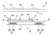
メンテナンスユニット19には、図6に示すワイピング機構30が搭載されている。ワイピング機構30は、複数のワイパー35a〜35c(図7参照)が固定された略矩形状のキャリッジ31と、キャリッジ31を支持する支持フレーム40とで構成されている。支持フレーム40の上面の対向する端縁にはレール部41a、41bが形成されており、キャリッジ31の四隅に設けられた摺動コロ36がレール部41a、41bに当接することで、キャリッジ31は支持フレーム40に対し矢印AA′方向に摺動可能に支持される。
A
図7に示すように、キャリッジ31は、支持フレーム40のレール部41a、41bに摺動コロ36を介して摺動可能に係合する第1ステー32a、32bと、第1ステー32a、32bの間に橋渡し状に固定された第2ステー33a、33b、33cとで枠体状に形成されている。
As illustrated in FIG. 7, the
第1ステー32aには、支持フレーム40に保持された入力ギア43(図6参照)に噛み合うラック歯38が形成されている。入力ギア43が正逆方向に回転すると、キャリッジ31は支持フレーム40に沿って水平方向(図6の矢印AA′方向)に往復移動する。なお、ラック歯38および入力ギア43によって、本発明の駆動機構が構成されている。
ワイパー35a〜35cは、各記録ヘッド17a〜17cの吐出ノズル18から押し出されたインクを拭き取るための部材である。ワイパー35a〜35cは、吐出ノズル18のノズル面が露出するノズル領域R(図5参照)の外側の位置に略垂直方向から圧接され、キャリッジ31の移動によりノズル領域Rを含むインク吐出面Fを所定方向(図6の矢印AA′方向)に拭き取る。
The
第2ステー33aには4枚のワイパー35aが略等間隔で固定されており、同様に、第2ステー33bには4枚のワイパー35bが、第2ステー33cには4枚のワイパー35cが略等間隔で固定されている。ワイパー35a、35cは、それぞれ各ラインヘッド11C〜11Kを構成する左右の記録ヘッド17a、17c(図3参照)に対応する位置に配置されている。また、ワイパー35bは、各ラインヘッド11C〜11Kを構成する中央の記録ヘッド17b(図3参照)に対応する位置に配置されており、ワイパー35a、35cに対しキャリッジ31の移動方向(図6の矢印AA′方向)と直交する方向に所定距離だけずらして固定されている。
Four
図8および図9に示すように、ワイパー35a〜35cの各々は、矢印A方向(第1方向)に向かって配置される第1拭き取り面35dと、矢印A方向とは反対方向(第2方向)に向かって配置される第2拭き取り面35eと、第1拭き取り面35dおよび第2拭き取り面35eの間に配置される上面35fと、を含んでいる。
As shown in FIGS. 8 and 9, each of the
第1拭き取り面35dは、後述する第1拭き取り動作時に、後述する第1インク押出動作により押出されたパージインク22b(図18参照)を拭き取る。第1拭き取り面35dの第1上端部35gは、第1拭き取り動作においてワイパー35a〜35cが矢印A方向に移動する際にインク吐出面Fに圧接される。
The
第2拭き取り面35eは、後述する第2拭き取り動作時に、後述する第2インク押出動作により押出されたパージインク22c(図25参照)を拭き取る。第2拭き取り面35eの第2上端部35hは、第2拭き取り動作においてワイパー35a〜35cが矢印A方向とは反対方向(矢印A′方向)に移動する際にインク吐出面Fに圧接される。
The
上面35fには、第1上端部35gと第2上端部35hとの間に、上方に突出する側面視矩形状の凸部Cが形成されている。第1上端部35gと凸部Cとの間には第1上端部35g側から第2上端部35h側に向かって高くなる(上がる)第1段差部L1が形成されているとともに、凸部Cと第2上端部35hとの間には第1上端部35g側から第2上端部35h側に向かって低くなる(下がる)第2段差部L2が形成されている。なお、凸部C(第1段差部L1、第2段差部L2)は、後述する第1拭き取り動作および第2拭き取り動作においてワイパー35a〜35cが矢印AA′方向に移動する際にインク吐出面Fに接触しない。
On the
例えば、ワイパー35a〜35cは、矢印A方向から見て約2.5mmの幅を有し、断面視で約1.0mmの幅(第1拭き取り面35dと第2拭き取り面35eとの距離)を有するように形成されている。また、凸部Cは、断面視で約0.5mm角に形成されている。
For example, the
図7に示すように、第2ステー33a、33cの上面の4箇所にはギャップコロ37が設けられている。ギャップコロ37は、ワイパー35a〜35cによる記録ヘッド17a〜17cのインク吐出面Fの拭き取り動作を行うためにワイピング機構30を記録部9側に上昇させたとき、記録部9のヘッドハウジング10に当接することでワイパー35a〜35cとインク吐出面Fとの接触状態を一定に保持する。
As shown in FIG. 7,
図10に示すように、支持フレーム40の上面には、ワイパー35a〜35cによってインク吐出面Fから拭き取られた廃インクを回収するためのインク回収トレイ44が配置されている。インク回収トレイ44の略中央部には、第2ステー33a〜33cの延在方向に沿って溝部44aが形成されており、溝部44aを挟んで両側のトレイ面44b、44cは、溝部44aに向かって下り勾配となっている。溝部44a内にはインク排出孔44dが設けられており、溝部44aの底面はインク排出孔44dに向かって下り勾配となっている。
As shown in FIG. 10, an
ワイパー35a〜35cによってインク吐出面Fから拭き取られ、トレイ面44b、44cに落下した廃インクは溝部44aに集められ、さらに溝部44a内をインク排出孔44dに向かって流れる。その後、インク排出孔44dに連結されたインク回収路(図示せず)を通って廃インク回収タンク(図示せず)に回収される。
Waste ink that has been wiped off from the ink discharge surface F by the
次に、本実施形態のワイピング機構30を昇降させるための昇降機構50について説明する。メンテナンスユニット19は、図11に示すユニット筐体45と、ユニット筐体45に取り付けられるワイピング機構30(図6参照)と、ユニット筐体45に配置される昇降機構50と、を含んでいる。ユニット筐体45の底面45aには図11および図12に示すように、2個のリフト部材50aがシャフト50bの両端に固定された昇降機構50が、キャリッジ31の移動方向(図6の矢印AA′方向)に対向する側面45b、45cに沿って一対配置されている。即ち、昇降機構50は、記録部9のヘッドハウジング10の幅方向両端(図2の上下両端部)に対向する位置に配置される。なお、図11では側面45c側の昇降機構50の記載を省略している。また、ユニット筐体45の側面45b、45cに隣接する側面45dには、モーター47と、モーター47の回転駆動力をシャフト50bに伝達する駆動伝達軸48とが付設されている。
Next, the elevating
図14に示すように、リフト部材50aの下端部はシャフト50bに固定されており、シャフト50bの回転に伴いリフト部材50aは揺動する。リフト部材50aの上端部には押し上げコロ53が回転自在に付設されている。また、押し上げコロ53は、コイルバネ55によってシャフト50bから離間する方向(図14では上方向)に付勢されている。
As shown in FIG. 14, the lower end portion of the
図12の状態から、右側の昇降機構50のシャフト50bを時計回り方向に、左側の昇降機構50のシャフト50bを反時計回り方向に回転すると、ユニット筐体45の内側に倒れ込んだリフト部材50aが外側方向(矢印B方向)に立ち上がる。これにより、リフト部材50aは水平状態から起立状態(図13の状態)に切り替えられ、支持フレーム40と共にキャリッジ31を上昇させる。
When the
一方、図13の状態から、右側の昇降機構50のシャフト50bを反時計回り方向に、左側の昇降機構50のシャフト50bを時計回り方向に回転すると、リフト部材50aがユニット筐体45の内側方向(矢印B′方向)に倒れ込む。これにより、リフト部材50aは起立状態から水平状態(図12の状態)に切り替えられ、支持フレーム40と共にキャリッジ31を下降させる。
On the other hand, when the
次に、本実施形態のインクジェット記録装置100における、ワイピング機構30を用いた記録ヘッド17a〜17cの回復動作について説明する。なお、図16、図17および図30では、記録部9及びメンテナンスユニット19を用紙搬送方向下流側(図15の左側)から見た状態を示している。また、支持フレーム40は簡略化して板状に記載しており、ユニット筐体45は底面45aのみを記載している。また、以下で説明する記録ヘッド17a〜17cの回復動作およびキャップユニット装着動作は、制御部110(図1参照)からの制御信号に基づいて記録ヘッド17a〜17c、ワイピング機構30、昇降機構50等の動作を制御することによって実行される。
Next, the recovery operation of the recording heads 17a to 17c using the
記録ヘッド17a〜17cの回復動作を行う場合、先ず、図15に示すように、記録部9の下方に位置する第1搬送ユニット5を下降させる。そして、第2搬送ユニット12の下方に配置されたメンテナンスユニット19を水平移動させて記録部9と第1搬送ユニット5との間に配置する。この状態では、図16に示すように、昇降機構50のリフト部材50aは水平状態にあり、キャリッジ31に固定されたワイパー35a〜35cは記録ヘッド17a〜17cのインク吐出面Fから離間している。
When the recovery operation of the recording heads 17a to 17c is performed, first, the
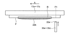
(第1インク押出動作)
ワイピング動作(後述の第1拭き取り動作)に先立って、インク22が記録ヘッド17a〜17cに供給される。図18に示すように、供給されたインク22は吐出ノズル18から強制的に押出(パージ)される。このパージ動作により、吐出ノズル18内の増粘インク、異物や気泡が排出され、記録ヘッド17a〜17cを回復することができる。このとき、図19に示すように、パージインク22bは吐出ノズル18の存在するノズル領域Rの形状に沿ってインク吐出面Fに押出される。
(First ink extrusion operation)
Prior to the wiping operation (first wiping operation described later), the
(第1拭き取り動作)
ワイパー35a〜35cを、記録ヘッド17a〜17cのインク吐出面Fの、ノズル領域Rの外側の第1位置P1に所定の圧力で接触させる。具体的には、図17および図18に示すように、昇降機構50のシャフト50bを回転させてリフト部材50aを矢印B方向に起立させることにより、支持フレーム40及びキャリッジ31を持ち上げる。このとき、リフト部材50aのコイルバネ55(図14参照)の付勢力によってキャリッジ31に設けられたギャップコロ37がヘッドハウジング10の下面に押し当てられるため、ワイパー35a〜35cをインク吐出面Fに対し常に一定の圧力で圧接させることができる。
(First wiping operation)
The
ワイパー35a〜35cの先端がインク吐出面Fに圧接した状態から、入力ギア43(図6参照)を正回転させてキャリッジ31を図17の矢印A方向に移動させることにより、キャリッジ31に支持されたワイパー35a〜35cも図20に示すようにインク吐出面Fに圧接された状態でインク吐出面Fに沿ってノズル領域Rの方向(左方向、第1方向、矢印A方向)に移動する。支持フレーム40には昇降機構50によって上方向の力が作用しているため、キャリッジ31はギャップコロ37がヘッドハウジング10に押し当てられた状態を維持しながら矢印A方向に移動する。
From the state in which the tips of the
このとき、図20に示すように、前回の記録ヘッド回復動作時にワイパー35a〜35cの先端(上面35f)に残留し、長時間空気に触れて増粘した残留インク22aは、インク吐出面Fの第1位置P1に付着し、ワイパー35a〜35cの先端から離間する。
At this time, as shown in FIG. 20, the
なお、図21に示すように、第1拭き取り動作においてワイパー35a〜35cが矢印A方向に移動する際には、凸部C(第1段差部L1、第2段差部L2)はインク吐出面Fに接触しない。
As shown in FIG. 21, when the
そして、図22に示すように、ワイパー35a〜35cは、インク吐出面Fのパージインク22bを拭き取りながら左方向(矢印A方向)に移動し、ノズル領域Rに対して第1位置P1とは反対側の位置(第2位置P2、左端縁)に到達すると、左方向への移動が停止される。なお、ワイパー35a〜35cによって拭き取られた廃インクの大部分は、インク回収トレイ44(図10参照)に回収される。
As shown in FIG. 22, the
(離間動作)
第1拭き取り動作の実行後、図23に示すように、ワイパー35a〜35cをインク吐出面Fから離間させる。具体的には、昇降機構50のシャフト50b(図17参照)を逆回転させてリフト部材50aを矢印B′方向に揺動させて水平状態にすることにより、支持フレーム40及びキャリッジ31を下降させる。なお、ワイパー35a〜35cの上面35fには第1段差部L1が形成されているので、第1拭き取り面35d側のパージインク22bが第2拭き取り面35e側に移動するのを抑制することができる。このため、ワイパー35a〜35cをインク吐出面Fから離間させる際に、ワイパー35a〜35cの上面35fに付着するパージインク22bの量を低減することができる。また、ワイパー35a〜35cの上面35fに第1段差部L1を形成すること、及び第1拭き取り動作においてワイパー35a〜35cをインク吐出面Fの左端縁まで移動させることによって、ワイパー35a〜35cをインク吐出面Fから離間させる際に、パージインク22bがインク吐出面Fに残存するのを十分に抑制することができる。
(Separation operation)
After execution of the first wiping operation, the
(移動動作)
離間動作の実行後、図24に示すように、ワイパー35a〜35cを水平移動させる。具体的には、図23の状態から入力ギア43(図6参照)を逆回転させてキャリッジ31を矢印A′方向に移動させることにより、図24に示すように、キャリッジ31に支持されたワイパー35a〜35cが、第2位置P2に対してノズル領域Rと同じ方向(右方向)に移動する。なお、ワイパー35a〜35cを右方向に移動させずに後述する第2拭き取り動作を実行することも可能であるが、ワイパー35a〜35cを右方向に少し移動させることによって、第2拭き取り動作においてワイパー35a〜35cの上面35fがインク吐出面Fの左端部(角部)に接触して損傷するのを抑制することができる。
(Movement operation)
After execution of the separating operation, the
(第2インク押出動作)
移動動作の実行後、インク22が記録ヘッド17a〜17cに供給される。図25に示すように、供給されたインク22は吐出ノズル18から強制的に押出(パージ)される。これにより、第1インク押出動作と同様に、インク吐出面Fにパージインク22cが付着する。
(Second ink extrusion operation)
After executing the moving operation, the
(第2拭き取り動作)
その後、インク吐出面Fのパージインク22cおよび残留インク22aを拭き取るワイピング動作を行う。具体的には、昇降機構50のシャフト50bを回転させてリフト部材50aを矢印B方向に起立させることにより、支持フレーム40及びキャリッジ31を持ち上げる。これにより、ワイパー35a〜35cを、記録ヘッド17a〜17cのインク吐出面Fの、ノズル領域Rに対して左側の位置に所定の圧力で接触させる。そして、入力ギア43(図6参照)を逆回転させてキャリッジ31を矢印A′方向(右方向、第2方向)に移動させることにより、図26に示すように、ワイパー35a〜35cがインク吐出面Fに圧接された状態でインク吐出面Fに沿ってノズル領域Rの方向(右方向)に移動する。
(Second wiping operation)
Thereafter, a wiping operation for wiping the
なお、図27に示すように、第2拭き取り動作においてワイパー35a〜35cが矢印A′方向に移動する際には、凸部C(第1段差部L1、第2段差部L2)はインク吐出面Fに接触しない。
As shown in FIG. 27, when the
そして、第2インク押出動作により押出されたパージインク22cと、第1位置P1の残留インク22aと、が拭き取られる。このとき、図28に示すようにワイパー35a〜35cに拭き取られたパージインク22cが残留インク22aに接触した際に、残留インク22aがパージインク22cに溶解して残留インク22aの増粘が緩和される。
Then, the
その後、ワイパー35a〜35cが、それぞれ記録ヘッド17a〜17cのインク吐出面Fの端縁(図29の右端縁)まで移動し、ワイパー35a〜35cによって拭き取られた廃インクの大部分は流れ落ちてインク回収トレイ44(図10参照)に回収される。そして、図30に示すように、昇降機構50のシャフト50bを回転させてリフト部材50aを矢印B′方向に倒伏させることにより、ワイパー35a〜35cを、記録ヘッド17a〜17cのインク吐出面Fから下方に退避させてメンテナンスユニット19を図16の状態に戻す。
Thereafter, the
なお、図9に示すようにワイパー35a〜35cの上面35fには第2段差部L2が形成されているので、図31に示すように第2拭き取り面35e側のパージインク22cが第1拭き取り面35d側に移動するのを抑制することができる。このため、ワイパー35a〜35cをインク吐出面Fから離間させる際に、ワイパー35a〜35cの上面35fに付着するパージインク22cの量を低減することができる。また、ワイパー35a〜35cの上面35fに第2段差部L2を形成すること、及び第2拭き取り動作においてワイパー35a〜35cをインク吐出面Fの右端縁まで移動させることによって、ワイパー35a〜35cをインク吐出面Fから離間させる際に、パージインク22cがインク吐出面Fに残存するのを十分に抑制することができる。
Since the second step portion L2 is formed on the
最後に、記録部9と第1搬送ユニット5との間に配置されたメンテナンスユニット19を水平移動させて第2搬送ユニット12の下方に配置し、第1搬送ユニット5を所定の位置まで上昇させて記録ヘッド17a〜17cの回復動作を終了する。
Finally, the
記録ヘッド17a〜17cにキャップユニット90を装着する場合は、先ず、図15に示すように、記録部9の下面に対向配置されている第1ベルト搬送部5を下降させる。そして、第2ベルト搬送部12の下方に配置されたキャップユニット90を記録部9と第1ベルト搬送部5との間に水平移動させて記録部9に対向する位置に配置する。
When the
次いで、第1ベルト搬送部5を上昇させることにより、キャップユニット90が押し上げられる。そして、キャップユニット90が記録ヘッド17a〜17cに密着した時点で第1ベルト搬送部5の上昇を停止させることにより、キャップユニット90の装着を完了する。
Next, the
本実施形態では、上記のように、第1拭き取り動作の実行後、ノズル領域Rに対して第1位置P1とは反対側の位置からノズル領域Rに対して第1位置P1側の位置まで、ワイパー35a〜35cをインク吐出面Fに沿って移動させる第2拭き取り動作を実行することによって、ワイパー35a〜35cにより第1位置P1の残留インク22aを拭き取ることができる。これにより、インク吐出面Fに残留インク22aが溜まるのを抑制することができるので、大きなインク溜まりが発生するのを抑制することができる。また、インク吐出面Fに順次接触する2枚のワイパー35a〜35cを設ける場合(上記特許文献1の構成)と異なり、ワイパー35a〜35cの数が多くなるのを抑制することができるので、記録ヘッド17a〜17cの回復システムの構造が複雑になるのを抑制することができる。
In the present embodiment, as described above, after the first wiping operation is performed, from the position opposite to the first position P1 with respect to the nozzle area R to the position on the first position P1 side with respect to the nozzle area R, By executing the second wiping operation for moving the
また、ワイパー35a〜35cの上面35fには、凸部Cが形成されており、第1上端部35gと凸部Cとの間には、第1上端部35g側から第2上端部35h側に向かって高くなる第1段差部L1が形成されている。これにより、第1上端部35g側から第2上端部35h側にインク22が移動するのを第1段差部L1によって抑制することができるので、第1拭き取り面35dで拭き取ったインク22が第2上端部35hに付着するのを抑制することができる。このため、第2拭き取り動作の開始時に第2上端部35hのインク22が引き延ばされてインク吐出面Fに付着するのを抑制することができる。なお、第2上端部35hにインク22が少量だけ付着している場合、第2拭き取り動作を実行すると、インク22が引き延ばされてインク吐出面Fに付着し、拭き残しが生じてしまう。
Further, a convex portion C is formed on the
また、ワイパー35a〜35cの上面35fに第1段差部L1を形成することによって、第1拭き取り動作後の離間動作時にワイパー35a〜35cの上面35fやインク吐出面Fに付着するインク22の量を低減することができる。
Further, by forming the first step portion L1 on the
また、上記のように、第1段差部L1は、第1拭き取り動作においてワイパー35a〜35cが矢印A方向(左方向)に移動する際にインク吐出面Fに接触しない。これにより、第1上端部35gのみがインク吐出面Fに接触することになるので、第1上端部35gのインク吐出面Fに対する接触圧が変化するのを抑制することができる。
Further, as described above, the first step portion L1 does not contact the ink ejection surface F when the
また、上記のように、上面35fには、凸部Cと第2上端部35hとの間に、第1上端部35g側から第2上端部35h側に向かって低くなる第2段差部L2が形成されている。これにより、第2上端部35h側から第1上端部35g側にインク22が移動するのを第2段差部L2によって抑制することができる。このため、第2拭き取り動作後の離間動作時にワイパー35a〜35cの上面35fやインク吐出面Fに付着するインク22の量を低減することができる。
Further, as described above, the second stepped portion L2 that decreases from the first
また、上記のように、第2段差部L2は、第2拭き取り動作においてワイパー35a〜35cが矢印A′方向(右方向)に移動する際にインク吐出面Fに接触しない。これにより、第2上端部35hのみがインク吐出面Fに接触することになるので、第2上端部35hのインク吐出面Fに対する接触圧が変化するのを抑制することができる。
Further, as described above, the second step portion L2 does not contact the ink ejection surface F when the
また、上記のように、第2拭き取り動作において、ワイパー35a〜35cを矢印A′方向(右方向)に移動させることによって、ワイパー35a〜35cは第2インク押出動作時に押出されたパージインク22cを拭き取った後で第1位置P1の残留インク22aを拭き取ることになる。これにより、ワイパー35a〜35cが残留インク22aを拭き取る際に、増粘していないパージインク22cが、長時間大気にさらされて増粘した残留インク22aに接触するので、残留インク22aがパージインク22cに溶解して残留インク22aの増粘が緩和される。このため、第2拭き取り動作において、インク吐出面Fに付着した残留インク22aをワイパー35a〜35cにより、拭き取り易くすることができる。
Further, as described above, in the second wiping operation, the
また、上記のように、第1拭き取り動作の実行後、ワイパー35a〜35cをインク吐出面Fから離間させる離間動作を実行する。これにより、離間動作によってワイパー35a〜35cの撓み(変形)を一旦解消することができるので、第2拭き取り動作時に容易にワイパー35a〜35cの第2拭き取り面35eの第2上端部35hをインク吐出面Fに圧接させることができる。
Further, as described above, after the first wiping operation is performed, the separating operation for separating the
(第2実施形態)
次に、図32および図33を参照して、本発明の第2実施形態のインクジェット記録装置100に用いられるワイパー35a〜35cについて説明する。
(Second Embodiment)
Next, with reference to FIGS. 32 and 33,
本発明の第2実施形態では図32および図33に示すように、ワイパー35a〜35cの各々は上記第1実施形態と同様、第1拭き取り面35dと、第2拭き取り面35eと、上面35fと、を含んでいる。
In the second embodiment of the present invention, as shown in FIGS. 32 and 33, each of the
上面35fには、側面視矩形状の凸部Cが形成されている。第2実施形態では、凸部Cは、第2拭き取り面35eと面一に形成されており、第1上端部35gと凸部Cとの間には、第1上端部35g側から第2上端部35h側に向かって高くなる第1段差部L1が形成されている。なお、凸部C(第1段差部L1)は、第1拭き取り動作においてワイパー35a〜35cが矢印A方向に移動する際にインク吐出面Fに接触しない。
A convex portion C having a rectangular shape in side view is formed on the
例えば、ワイパー35a〜35cは、矢印A方向から見て約2.5mmの幅を有し、断面視で約1.5mmの幅(第1拭き取り面35dと第2拭き取り面35eとの距離)を有するように形成されている。また、凸部Cは、断面視で約0.5mm角に形成されている。すなわち、第1上端部35gと第1段差部L1との距離は約1.0mmであり、第1段差部L1の段差は約0.5mmである。
For example, the
第2実施形態のその他の構造、及び記録ヘッド17a〜17cの回復動作は、上記第1実施形態と同様である。 The other structure of the second embodiment and the recovery operation of the recording heads 17a to 17c are the same as those of the first embodiment.
本実施形態では、上記のように、ワイパー35a〜35cの凸部Cは、第2拭き取り面35eと面一に形成されている。この場合であっても、第1上端部35g側から第2上端部35h側にインク22が移動するのを第1段差部L1によって抑制することができるので、第1拭き取り面35dで拭き取ったインク22が第2上端部35hに付着するのを抑制することができる。また、第1拭き取り動作後の離間動作時にワイパー35a〜35cの上面35fやインク吐出面Fに付着するインク22の量を低減することができる。
In the present embodiment, as described above, the convex portions C of the
第2実施形態のその他の効果は、上記第1実施形態と同様である。 Other effects of the second embodiment are the same as those of the first embodiment.
(第3実施形態)
次に、図34を参照して、本発明の第3実施形態のインクジェット記録装置100について説明する。
(Third embodiment)
Next, with reference to FIG. 34, the
本発明の第3実施形態ではインクジェット記録装置100は図34に示すように、ワイパー35a〜35cの上面35fを清掃するクリーニング機構70を備えている。クリーニング機構70は、ワイパー35a〜35cの上面35fに付着したインク22が転写される繊維ウェブなどからなるクリーニング部材71と、クリーニング部材71が巻装された送出しローラー72と、送出しローラー72から送り出されたクリーニング部材71を巻き取る巻取りローラー73と、を含む。
In the third embodiment of the present invention, the ink
また、第3実施形態では、記録ヘッド17a〜17cの回復動作の第2拭き取り動作の実行後に、ワイパー35a〜35cの上面35fをクリーニング部材71に対して複数回接離させることによって、ワイパー35a〜35cの上面35fのインク22をクリーニング部材71に吸収させる。なお、クリーニング部材71の吸収力が低下した場合は、巻取りローラー73を回転させてクリーニング部材71の清浄な転写面にワイパー35a〜35cの上面35fを当接させることによって、クリーニング部材71の吸収力を回復させることができ、ワイパー35a〜35cの上面35fを十分に清掃することができる。
In the third embodiment, after the second wiping operation of the recovery operation of the recording heads 17 a to 17 c is performed, the
第3実施形態のその他の構造、及び記録ヘッド17a〜17cのその他の回復動作は、上記第1および第2実施形態と同様である。 Other structures of the third embodiment and other recovery operations of the recording heads 17a to 17c are the same as those of the first and second embodiments.
本実施形態では、上記のように、ワイパー35a〜35cの上面35fを清掃するクリーニング機構70を設ける。これにより、ワイパー35a〜35cの上面35fのインク22を除去することができるので、次回の回復処理時にワイパー35a〜35cに付着したインク22がインク吐出面Fに付着するのを抑制することができる。
In the present embodiment, as described above, the
第3実施形態のその他の効果は、上記第1および第2実施形態と同様である。 Other effects of the third embodiment are the same as those of the first and second embodiments.
なお、今回開示された実施形態は、すべての点で例示であって制限的なものではないと考えられるべきである。本発明の範囲は、上記した実施形態の説明ではなく特許請求の範囲によって示され、さらに特許請求の範囲と均等の意味および範囲内でのすべての変更が含まれる。 The embodiment disclosed this time should be considered as illustrative in all points and not restrictive. The scope of the present invention is shown not by the above description of the embodiments but by the scope of claims for patent, and further includes all modifications within the meaning and scope equivalent to the scope of claims for patent.
例えば、上記実施形態では、第1インク押出動作を、第1拭き取り動作の前に実行したが、ワイパー35a〜35cがノズル領域Rに進入する前であれば、第1拭き取り動作と同時に実行してもよい。
For example, in the above-described embodiment, the first ink extrusion operation is performed before the first wiping operation, but if the
また、上記実施形態では、第2インク押出動作を、離間動作の後に実行したが、離間動作の前に実行してもよいし、ワイパー35a〜35cがノズル領域Rに進入する前であれば、第2拭き取り動作と同時に実行してもよい。
In the above embodiment, the second ink extrusion operation is performed after the separation operation. However, the second ink extrusion operation may be performed before the separation operation or before the
また、例えば上記第1実施形態では、ワイパー35a〜35cの凸部C(第1段差部L1、第2段差部L2)を、第1拭き取り動作および第2拭き取り動作においてワイパー35a〜35cが矢印AA′方向に移動する際にインク吐出面Fに接触しないように形成した例について示したが、本発明はこれに限らない。例えば、第1拭き取り動作においてワイパー35a〜35cが矢印A方向に移動する際に第1上端部35gと凸部C(第1段差部L1)との両方がインク吐出面Fに接触するように、ワイパー35a〜35cを形成してもよい。また、第2拭き取り動作においてワイパー35a〜35cが矢印A′方向に移動する際に第2上端部35hと凸部C(第2段差部L2)との両方がインク吐出面Fに接触するように、ワイパー35a〜35cを形成してもよい。ただし、第1上端部35gおよび第2上端部35hのインク吐出面Fに対する接触圧が変化するのを抑制するためには、第1拭き取り動作および第2拭き取り動作においてワイパー35a〜35cが矢印AA′方向に移動する際にインク吐出面Fに接触しないように、ワイパー35a〜35cを形成することが好ましい。
Further, for example, in the first embodiment, the protrusions C (the first stepped portion L1 and the second stepped portion L2) of the
また、駆動機構(ラック歯38、入力ギア43)や昇降機構50は、従来公知の他の駆動機構や昇降機構を用いることができる。記録ヘッド17a〜17cの吐出ノズル18の個数やノズル間隔等もインクジェット記録装置100の仕様に応じて適宜設定することができる。また、記録ヘッドの数も特に限定されるものではなく、例えば各ラインヘッド11C〜11Kにつき記録ヘッド17を1個、2個、或いは4個以上配置することもできる。
As the drive mechanism (rack
また、本発明は、ラインヘッド11C〜11Kのうちいずれか1つのみを備えた単色印刷用のインクジェット記録装置にも適用できる。その場合、記録ヘッド17a〜17cは1つずつ設けられるため、記録ヘッド17a〜17cに対応するワイパー35a〜35cもキャリッジ31に1枚ずつ固定すれば良い。
Further, the present invention can also be applied to an inkjet recording apparatus for monochrome printing that includes only one of the line heads 11C to 11K. In that case, since the recording heads 17a to 17c are provided one by one, the
17a〜17c 記録ヘッド
18 吐出ノズル
22 インク
22b、22c パージインク
35a〜35c ワイパー
35d 第1拭き取り面
35e 第2拭き取り面
35f 上面
35g 第1上端部
35h 第2上端部
38 ラック歯(駆動機構)
43 入力ギア(駆動機構)
100 インクジェット記録装置
110 制御部
C 凸部
F インク吐出面
L1 第1段差部
L2 第2段差部
P1 第1位置
P2 第2位置
R ノズル領域
S 用紙(記録媒体)
17a to
43 Input gear (drive mechanism)
DESCRIPTION OF
Claims (7)
前記吐出ノズルから強制的に押出されたパージインクを拭き取るワイパーと、
該ワイパーを、前記ノズル領域を含むインク吐出面に沿って往復移動させる駆動機構と、
前記吐出ノズルからのインクの押し出し及び吐出、並びに前記駆動機構の動作を制御する制御部と、
を備え、
前記制御部は、
前記吐出ノズルからインクを強制的に押出して前記ノズル領域に前記パージインクを付着させる第1インク押出動作と、
前記インク吐出面における前記ノズル領域の外側の第1位置に前記ワイパーを圧接させた後、前記ワイパーを前記インク吐出面に圧接させた状態で前記インク吐出面に沿って前記ノズル領域側に向かう第1方向に移動させることにより、前記パージインクを拭き取り、前記ノズル領域に対して前記第1位置とは反対側の第2位置まで前記ワイパーを移動させる第1拭き取り動作と、
前記ノズル領域に対して前記第1位置とは反対側の位置から前記ノズル領域に対して前記第1位置側の位置まで、前記ワイパーを前記インク吐出面に圧接させた状態で前記インク吐出面に沿って移動させる第2拭き取り動作と、
を含む前記記録ヘッドの回復動作を実行可能であり、
前記ワイパーは、前記第1方向に向かって配置される第1拭き取り面と、前記第1方向とは反対の第2方向に向かって配置される第2拭き取り面と、前記第1拭き取り面および前記第2拭き取り面の間に配置される上面と、を含み、
前記第1拭き取り面は、前記第1拭き取り動作において前記ワイパーが前記第1方向に移動する際に前記インク吐出面に接触する第1上端部を含み、
前記第2拭き取り面は、前記第2拭き取り動作において前記ワイパーが前記第2方向に移動する際に前記インク吐出面に接触する第2上端部を含み、
前記上面には、前記第1上端部と前記第2上端部との間に側面視矩形状の凸部が形成されており、前記第1上端部と前記凸部との間に前記第1上端部側から前記第2上端部側に向かって高くなる第1段差部が形成され、
前記第1段差部は、前記第1拭き取り動作において前記ワイパーが前記第1方向に移動する際に前記インク吐出面に接触しないことを特徴とする記録ヘッドの回復システム。 A recording head recovery system provided with a nozzle region in which a discharge nozzle for discharging ink is opened on a recording medium,
A wiper for wiping the purge ink forced out of the discharge nozzle;
A drive mechanism for reciprocating the wiper along an ink ejection surface including the nozzle region;
A controller that controls the ejection and ejection of ink from the ejection nozzle and the operation of the drive mechanism;
With
The controller is
A first ink extruding operation for forcibly extruding ink from the ejection nozzle and attaching the purge ink to the nozzle region;
After the wiper is brought into pressure contact with the first position outside the nozzle region on the ink ejection surface, the wiper is moved toward the nozzle region along the ink ejection surface with the wiper being in pressure contact with the ink ejection surface. A first wiping operation for wiping the purge ink by moving in one direction and moving the wiper to a second position opposite to the first position with respect to the nozzle region;
From the position opposite to the first position with respect to the nozzle area to the position on the first position side with respect to the nozzle area, the wiper is brought into pressure contact with the ink discharge surface. A second wiping action to be moved along,
A recovery operation of the recording head including:
The wiper includes a first wiping surface disposed toward the first direction, a second wiping surface disposed toward a second direction opposite to the first direction, the first wiping surface, and the An upper surface disposed between the second wiping surfaces,
The first wiping surface includes a first upper end portion that contacts the ink ejection surface when the wiper moves in the first direction in the first wiping operation;
The second wiping surface includes a second upper end portion that contacts the ink ejection surface when the wiper moves in the second direction in the second wiping operation,
A convex portion having a rectangular shape in a side view is formed on the upper surface between the first upper end portion and the second upper end portion, and the first upper end is formed between the first upper end portion and the convex portion. A first stepped portion is formed which increases from the portion side toward the second upper end portion side ,
The recording head recovery system, wherein the first step portion does not contact the ink ejection surface when the wiper moves in the first direction in the first wiping operation .
前記吐出ノズルから強制的に押出されたパージインクを拭き取るワイパーと、
該ワイパーを、前記ノズル領域を含むインク吐出面に沿って往復移動させる駆動機構と、
前記吐出ノズルからのインクの押し出し及び吐出、並びに前記駆動機構の動作を制御する制御部と、
を備え、
前記制御部は、
前記吐出ノズルからインクを強制的に押出して前記ノズル領域に前記パージインクを付着させる第1インク押出動作と、
前記インク吐出面における前記ノズル領域の外側の第1位置に前記ワイパーを圧接させた後、前記ワイパーを前記インク吐出面に圧接させた状態で前記インク吐出面に沿って前記ノズル領域側に向かう第1方向に移動させることにより、前記パージインクを拭き取り、前記ノズル領域に対して前記第1位置とは反対側の第2位置まで前記ワイパーを移動させる第1拭き取り動作と、
前記ノズル領域に対して前記第1位置とは反対側の位置から前記ノズル領域に対して前記第1位置側の位置まで、前記ワイパーを前記インク吐出面に圧接させた状態で前記インク吐出面に沿って移動させる第2拭き取り動作と、
を含む前記記録ヘッドの回復動作を実行可能であり、
前記ワイパーは、前記第1方向に向かって配置される第1拭き取り面と、前記第1方向とは反対の第2方向に向かって配置される第2拭き取り面と、前記第1拭き取り面および前記第2拭き取り面の間に配置される上面と、を含み、
前記第1拭き取り面は、前記第1拭き取り動作において前記ワイパーが前記第1方向に移動する際に前記インク吐出面に接触する第1上端部を含み、
前記第2拭き取り面は、前記第2拭き取り動作において前記ワイパーが前記第2方向に移動する際に前記インク吐出面に接触する第2上端部を含み、
前記上面には、前記第1上端部と前記第2上端部との間に側面視矩形状の凸部が形成されており、前記第1上端部と前記凸部との間に前記第1上端部側から前記第2上端部側に向かって高くなる第1段差部が形成され、前記凸部と前記第2上端部との間に、前記第1上端部側から前記第2上端部側に向かって低くなる第2段差部が形成されていることを特徴とする記録ヘッドの回復システム。 A recording head recovery system provided with a nozzle region in which a discharge nozzle for discharging ink is opened on a recording medium,
A wiper for wiping the purge ink forced out of the discharge nozzle;
A drive mechanism for reciprocating the wiper along an ink ejection surface including the nozzle region;
A controller that controls the ejection and ejection of ink from the ejection nozzle and the operation of the drive mechanism;
With
The controller is
A first ink extruding operation for forcibly extruding ink from the ejection nozzle and attaching the purge ink to the nozzle region;
After the wiper is brought into pressure contact with the first position outside the nozzle region on the ink ejection surface, the wiper is moved toward the nozzle region along the ink ejection surface with the wiper being in pressure contact with the ink ejection surface. A first wiping operation for wiping the purge ink by moving in one direction and moving the wiper to a second position opposite to the first position with respect to the nozzle region;
From the position opposite to the first position with respect to the nozzle area to the position on the first position side with respect to the nozzle area, the wiper is brought into pressure contact with the ink discharge surface. A second wiping action to be moved along,
A recovery operation of the recording head including:
The wiper includes a first wiping surface disposed toward the first direction, a second wiping surface disposed toward a second direction opposite to the first direction, the first wiping surface, and the An upper surface disposed between the second wiping surfaces,
The first wiping surface includes a first upper end portion that contacts the ink ejection surface when the wiper moves in the first direction in the first wiping operation;
The second wiping surface includes a second upper end portion that contacts the ink ejection surface when the wiper moves in the second direction in the second wiping operation,
A convex portion having a rectangular shape in a side view is formed on the upper surface between the first upper end portion and the second upper end portion, and the first upper end is formed between the first upper end portion and the convex portion. A first stepped portion is formed which becomes higher from the portion side toward the second upper end portion side, and between the convex portion and the second upper end portion, from the first upper end portion side to the second upper end portion side. A recovery system for a recording head, wherein a second stepped portion that becomes lower is formed .
前記第1拭き取り動作の実行後、前記吐出ノズルからインクを強制的に押出して前記ノズル領域に前記パージインクを付着させる第2インク押出動作を実行するとともに、
前記第2拭き取り動作時に、前記ワイパーを前記インク吐出面に圧接させた状態で前記インク吐出面に沿って前記第2方向に移動させることにより、前記第2インク押出動作時に押出された前記パージインクを拭き取ることを特徴とする請求項1〜4のいずれか1項に記載の記録ヘッドの回復システム。 The controller is
After performing the first wiping operation, performing a second ink extrusion operation for forcibly extruding ink from the ejection nozzle and attaching the purge ink to the nozzle region;
The purge ink pushed out during the second ink extruding operation by moving the wiper in the second direction along the ink ejecting surface with the wiper pressed against the ink ejecting surface during the second wiping operation recovery system of the recording head according to any one of claims 1 to 4, characterized in that wiping.
前記吐出ノズルから強制的に押出されたパージインクを拭き取るワイパーと、
該ワイパーを、前記ノズル領域を含むインク吐出面に沿って往復移動させる駆動機構と、
前記吐出ノズルからのインクの押し出し及び吐出、並びに前記駆動機構の動作を制御する制御部と、
を備え、
前記制御部は、
前記吐出ノズルからインクを強制的に押出して前記ノズル領域に前記パージインクを付着させる第1インク押出動作と、
前記インク吐出面における前記ノズル領域の外側の第1位置に前記ワイパーを圧接させた後、前記ワイパーを前記インク吐出面に圧接させた状態で前記インク吐出面に沿って前記ノズル領域側に向かう第1方向に移動させることにより、前記パージインクを拭き取り、前記ノズル領域に対して前記第1位置とは反対側の第2位置まで前記ワイパーを移動させる第1拭き取り動作と、
前記ノズル領域に対して前記第1位置とは反対側の位置から前記ノズル領域に対して前記第1位置側の位置まで、前記ワイパーを前記インク吐出面に圧接させた状態で前記インク吐出面に沿って移動させる第2拭き取り動作と、
を含む前記記録ヘッドの回復動作を実行可能であり、
前記ワイパーは、前記第1方向に向かって配置される第1拭き取り面と、前記第1方向とは反対の第2方向に向かって配置される第2拭き取り面と、前記第1拭き取り面および前記第2拭き取り面の間に配置される上面と、を含み、
前記第1拭き取り面は、前記第1拭き取り動作において前記ワイパーが前記第1方向に移動する際に前記インク吐出面に接触する第1上端部を含み、
前記第2拭き取り面は、前記第2拭き取り動作において前記ワイパーが前記第2方向に移動する際に前記インク吐出面に接触する第2上端部を含み、
前記上面には、前記第1上端部と前記第2上端部との間に側面視矩形状の凸部が形成されており、前記第1上端部と前記凸部との間に前記第1上端部側から前記第2上端部側に向かって高くなる第1段差部が形成され、
前記制御部は、
前記第1拭き取り動作の実行後、前記ワイパーを前記インク吐出面から離間させる離間動作を実行することを特徴とする記録ヘッドの回復システム。 A recording head recovery system provided with a nozzle region in which a discharge nozzle for discharging ink is opened on a recording medium,
A wiper for wiping the purge ink forced out of the discharge nozzle;
A drive mechanism for reciprocating the wiper along an ink ejection surface including the nozzle region;
A controller that controls the ejection and ejection of ink from the ejection nozzle and the operation of the drive mechanism;
With
The controller is
A first ink extruding operation for forcibly extruding ink from the ejection nozzle and attaching the purge ink to the nozzle region;
After the wiper is brought into pressure contact with the first position outside the nozzle region on the ink ejection surface, the wiper is moved toward the nozzle region along the ink ejection surface with the wiper being in pressure contact with the ink ejection surface. A first wiping operation for wiping the purge ink by moving in one direction and moving the wiper to a second position opposite to the first position with respect to the nozzle region;
From the position opposite to the first position with respect to the nozzle area to the position on the first position side with respect to the nozzle area, the wiper is brought into pressure contact with the ink discharge surface. A second wiping action to be moved along,
A recovery operation of the recording head including:
The wiper includes a first wiping surface disposed toward the first direction, a second wiping surface disposed toward a second direction opposite to the first direction, the first wiping surface, and the An upper surface disposed between the second wiping surfaces,
The first wiping surface includes a first upper end portion that contacts the ink ejection surface when the wiper moves in the first direction in the first wiping operation;
The second wiping surface includes a second upper end portion that contacts the ink ejection surface when the wiper moves in the second direction in the second wiping operation,
A convex portion having a rectangular shape in a side view is formed on the upper surface between the first upper end portion and the second upper end portion, and the first upper end is formed between the first upper end portion and the convex portion. A first stepped portion is formed which increases from the portion side toward the second upper end portion side ,
The controller is
A recovery system for a recording head , wherein a separation operation for separating the wiper from the ink ejection surface is performed after the first wiping operation is performed .
An ink jet recording apparatus characterized by comprising a recovery system for the recording head according to any one of claims 1-6.
Priority Applications (2)
| Application Number | Priority Date | Filing Date | Title |
|---|---|---|---|
| JP2014263990A JP6332020B2 (en) | 2014-12-26 | 2014-12-26 | Recording head recovery system and ink jet recording apparatus including the same |
| US14/961,253 US9421776B2 (en) | 2014-12-26 | 2015-12-07 | Recovery system for recording head and ink-jet recording apparatus including the same |
Applications Claiming Priority (1)
| Application Number | Priority Date | Filing Date | Title |
|---|---|---|---|
| JP2014263990A JP6332020B2 (en) | 2014-12-26 | 2014-12-26 | Recording head recovery system and ink jet recording apparatus including the same |
Publications (2)
| Publication Number | Publication Date |
|---|---|
| JP2016124109A JP2016124109A (en) | 2016-07-11 |
| JP6332020B2 true JP6332020B2 (en) | 2018-05-30 |
Family
ID=56163225
Family Applications (1)
| Application Number | Title | Priority Date | Filing Date |
|---|---|---|---|
| JP2014263990A Active JP6332020B2 (en) | 2014-12-26 | 2014-12-26 | Recording head recovery system and ink jet recording apparatus including the same |
Country Status (2)
| Country | Link |
|---|---|
| US (1) | US9421776B2 (en) |
| JP (1) | JP6332020B2 (en) |
Families Citing this family (4)
| Publication number | Priority date | Publication date | Assignee | Title |
|---|---|---|---|---|
| JP7039901B2 (en) * | 2016-11-10 | 2022-03-23 | 株式会社リコー | Head cleaning device, head maintenance device, liquid discharge device |
| US10556433B2 (en) * | 2018-01-29 | 2020-02-11 | Canon Kabushiki Kaisha | Liquid discharge apparatus and cleaning method for liquid discharge head |
| JP7081266B2 (en) * | 2018-03-29 | 2022-06-07 | 京セラドキュメントソリューションズ株式会社 | Wipe unit and inkjet recording device equipped with it |
| US11383525B2 (en) | 2020-06-10 | 2022-07-12 | Xerox Corporation | System and method for efficiently purging printheads |
Family Cites Families (9)
| Publication number | Priority date | Publication date | Assignee | Title |
|---|---|---|---|---|
| US6631974B2 (en) * | 2001-02-13 | 2003-10-14 | Brother Kogyo Kabushiki Kaisha | Ink jet recording apparatus having wiping mechanism |
| US6547369B1 (en) * | 2001-10-12 | 2003-04-15 | Xerox Corporation | Layered cleaning blade and image forming device arranged with the same |
| JP4258616B2 (en) * | 2003-03-06 | 2009-04-30 | セイコーエプソン株式会社 | Wiping member |
| JP4895723B2 (en) * | 2006-08-23 | 2012-03-14 | 富士フイルム株式会社 | Liquid ejection apparatus and liquid ejection surface cleaning method |
| US7914110B2 (en) * | 2007-01-31 | 2011-03-29 | Hewlett-Packard Development Company, L.P. | Purging fluid from fluid-ejection nozzles by performing spit-wipe operations |
| JP2009262332A (en) * | 2008-04-22 | 2009-11-12 | Brother Ind Ltd | Recording apparatus |
| JP5481445B2 (en) * | 2011-08-31 | 2014-04-23 | 京セラドキュメントソリューションズ株式会社 | Wiping mechanism and ink jet recording apparatus having the same |
| JP5891750B2 (en) * | 2011-11-30 | 2016-03-23 | ブラザー工業株式会社 | Inkjet recording device |
| JP5892099B2 (en) * | 2013-03-27 | 2016-03-23 | ブラザー工業株式会社 | Liquid ejection device |
-
2014
- 2014-12-26 JP JP2014263990A patent/JP6332020B2/en active Active
-
2015
- 2015-12-07 US US14/961,253 patent/US9421776B2/en active Active
Also Published As
| Publication number | Publication date |
|---|---|
| US9421776B2 (en) | 2016-08-23 |
| JP2016124109A (en) | 2016-07-11 |
| US20160185121A1 (en) | 2016-06-30 |
Similar Documents
| Publication | Publication Date | Title |
|---|---|---|
| JP5871860B2 (en) | RECOVERY MECHANISM OF RECORDING HEAD, INKJET RECORDING DEVICE EQUIPPED WITH THE RECOVERY MECHANISM, AND RECOVERY METHOD OF RECORDING HEAD | |
| JP6332020B2 (en) | Recording head recovery system and ink jet recording apparatus including the same | |
| JP5656916B2 (en) | Wiping mechanism and ink jet recording apparatus having the same | |
| JP5992556B2 (en) | RECOVERY SYSTEM OF PRINT HEAD, INKJET RECORDING DEVICE EQUIPPED WITH THE SAME, AND RECOVERY METHOD OF RECORD HEAD | |
| JP5987075B2 (en) | Inkjet recording device | |
| JP2009269327A (en) | Inkjet recorder | |
| JP6217610B2 (en) | Recording head recovery system and ink jet recording apparatus including the same | |
| JP6229669B2 (en) | RECOVERY SYSTEM OF PRINT HEAD, INKJET RECORDING DEVICE EQUIPPED WITH THE SAME, AND RECOVERY METHOD OF RECORD HEAD | |
| JP6308096B2 (en) | Inkjet recording device | |
| JP6915450B2 (en) | Inkjet recording device | |
| JP7081266B2 (en) | Wipe unit and inkjet recording device equipped with it | |
| JP6112727B2 (en) | RECOVERY MECHANISM OF PRINT HEAD, INKJET RECORDING DEVICE EQUIPPED WITH THE RECOVERY MECHANISM, AND RECOVERY METHOD OF RECORD HEAD | |
| JP6112726B2 (en) | RECOVERY MECHANISM OF PRINT HEAD, INKJET RECORDING DEVICE EQUIPPED WITH THE RECOVERY MECHANISM, AND RECOVERY METHOD OF RECORD HEAD | |
| JP6308103B2 (en) | RECOVERY SYSTEM OF PRINT HEAD, INKJET RECORDING DEVICE EQUIPPED WITH THE SAME, AND RECOVERY METHOD OF RECORD HEAD | |
| JP6308113B2 (en) | RECOVERY SYSTEM OF PRINT HEAD, INKJET RECORDING DEVICE EQUIPPED WITH THE SAME, AND RECOVERY METHOD OF RECORD HEAD | |
| JP6180389B2 (en) | RECOVERY SYSTEM OF PRINT HEAD, INKJET RECORDING DEVICE EQUIPPED WITH THE SAME, AND RECOVERY METHOD OF RECORD HEAD | |
| JP6221946B2 (en) | RECOVERY SYSTEM OF PRINT HEAD, INKJET RECORDING DEVICE EQUIPPED WITH THE SAME, AND RECOVERY METHOD OF RECORD HEAD | |
| JP6589893B2 (en) | Head cleaning mechanism and ink jet recording apparatus having the same | |
| JP6340924B2 (en) | RECOVERY SYSTEM OF PRINT HEAD, INKJET RECORDING DEVICE EQUIPPED WITH THE SAME, AND RECOVERY METHOD OF RECORD HEAD | |
| JP7176234B2 (en) | WIPE UNIT AND INKJET RECORDING DEVICE INCLUDING THE SAME | |
| JP6265164B2 (en) | RECOVERY SYSTEM OF PRINT HEAD, INKJET RECORDING DEVICE EQUIPPED WITH THE SAME, AND RECOVERY METHOD OF RECORD HEAD | |
| JP2018118441A (en) | Recovery system of recording heads and inkjet recording device including the same | |
| JP5009817B2 (en) | Image forming apparatus | |
| JP6617738B2 (en) | Head cleaning mechanism and ink jet recording apparatus having the same | |
| JP7155913B2 (en) | Maintenance unit and inkjet recording device equipped with the same |
Legal Events
| Date | Code | Title | Description |
|---|---|---|---|
| A621 | Written request for application examination |
Free format text: JAPANESE INTERMEDIATE CODE: A621 Effective date: 20161226 |
|
| A977 | Report on retrieval |
Free format text: JAPANESE INTERMEDIATE CODE: A971007 Effective date: 20170920 |
|
| A131 | Notification of reasons for refusal |
Free format text: JAPANESE INTERMEDIATE CODE: A131 Effective date: 20171031 |
|
| A521 | Request for written amendment filed |
Free format text: JAPANESE INTERMEDIATE CODE: A523 Effective date: 20171218 |
|
| TRDD | Decision of grant or rejection written | ||
| A01 | Written decision to grant a patent or to grant a registration (utility model) |
Free format text: JAPANESE INTERMEDIATE CODE: A01 Effective date: 20180403 |
|
| A61 | First payment of annual fees (during grant procedure) |
Free format text: JAPANESE INTERMEDIATE CODE: A61 Effective date: 20180416 |
|
| R150 | Certificate of patent or registration of utility model |
Ref document number: 6332020 Country of ref document: JP Free format text: JAPANESE INTERMEDIATE CODE: R150 |