JP6330050B2 - Switch base rack base assembly - Google Patents
Switch base rack base assembly Download PDFInfo
- Publication number
- JP6330050B2 JP6330050B2 JP2016546509A JP2016546509A JP6330050B2 JP 6330050 B2 JP6330050 B2 JP 6330050B2 JP 2016546509 A JP2016546509 A JP 2016546509A JP 2016546509 A JP2016546509 A JP 2016546509A JP 6330050 B2 JP6330050 B2 JP 6330050B2
- Authority
- JP
- Japan
- Prior art keywords
- frame
- base
- horizontal
- base assembly
- fixed support
- Prior art date
- Legal status (The legal status is an assumption and is not a legal conclusion. Google has not performed a legal analysis and makes no representation as to the accuracy of the status listed.)
- Active
Links
Images


Classifications
-
- H—ELECTRICITY
- H02—GENERATION; CONVERSION OR DISTRIBUTION OF ELECTRIC POWER
- H02B—BOARDS, SUBSTATIONS OR SWITCHING ARRANGEMENTS FOR THE SUPPLY OR DISTRIBUTION OF ELECTRIC POWER
- H02B1/00—Frameworks, boards, panels, desks, casings; Details of substations or switching arrangements
- H02B1/26—Casings; Parts thereof or accessories therefor
- H02B1/30—Cabinet-type casings; Parts thereof or accessories therefor
- H02B1/32—Mounting of devices therein
- H02B1/34—Racks
-
- H—ELECTRICITY
- H02—GENERATION; CONVERSION OR DISTRIBUTION OF ELECTRIC POWER
- H02B—BOARDS, SUBSTATIONS OR SWITCHING ARRANGEMENTS FOR THE SUPPLY OR DISTRIBUTION OF ELECTRIC POWER
- H02B1/00—Frameworks, boards, panels, desks, casings; Details of substations or switching arrangements
- H02B1/26—Casings; Parts thereof or accessories therefor
- H02B1/30—Cabinet-type casings; Parts thereof or accessories therefor
- H02B1/303—Bases or feet
-
- H—ELECTRICITY
- H02—GENERATION; CONVERSION OR DISTRIBUTION OF ELECTRIC POWER
- H02B—BOARDS, SUBSTATIONS OR SWITCHING ARRANGEMENTS FOR THE SUPPLY OR DISTRIBUTION OF ELECTRIC POWER
- H02B1/00—Frameworks, boards, panels, desks, casings; Details of substations or switching arrangements
- H02B1/01—Frameworks
- H02B1/011—Open support bases
-
- H—ELECTRICITY
- H02—GENERATION; CONVERSION OR DISTRIBUTION OF ELECTRIC POWER
- H02B—BOARDS, SUBSTATIONS OR SWITCHING ARRANGEMENTS FOR THE SUPPLY OR DISTRIBUTION OF ELECTRIC POWER
- H02B1/00—Frameworks, boards, panels, desks, casings; Details of substations or switching arrangements
- H02B1/01—Frameworks
- H02B1/013—Profiles for cabinet frames
-
- H—ELECTRICITY
- H02—GENERATION; CONVERSION OR DISTRIBUTION OF ELECTRIC POWER
- H02B—BOARDS, SUBSTATIONS OR SWITCHING ARRANGEMENTS FOR THE SUPPLY OR DISTRIBUTION OF ELECTRIC POWER
- H02B1/00—Frameworks, boards, panels, desks, casings; Details of substations or switching arrangements
- H02B1/01—Frameworks
- H02B1/014—Corner connections for frameworks
-
- H—ELECTRICITY
- H02—GENERATION; CONVERSION OR DISTRIBUTION OF ELECTRIC POWER
- H02B—BOARDS, SUBSTATIONS OR SWITCHING ARRANGEMENTS FOR THE SUPPLY OR DISTRIBUTION OF ELECTRIC POWER
- H02B1/00—Frameworks, boards, panels, desks, casings; Details of substations or switching arrangements
- H02B1/20—Bus-bar or other wiring layouts, e.g. in cubicles, in switchyards
- H02B1/202—Cable lay-outs
-
- H—ELECTRICITY
- H02—GENERATION; CONVERSION OR DISTRIBUTION OF ELECTRIC POWER
- H02B—BOARDS, SUBSTATIONS OR SWITCHING ARRANGEMENTS FOR THE SUPPLY OR DISTRIBUTION OF ELECTRIC POWER
- H02B1/00—Frameworks, boards, panels, desks, casings; Details of substations or switching arrangements
- H02B1/26—Casings; Parts thereof or accessories therefor
- H02B1/28—Casings; Parts thereof or accessories therefor dustproof, splashproof, drip-proof, waterproof or flameproof
-
- H—ELECTRICITY
- H05—ELECTRIC TECHNIQUES NOT OTHERWISE PROVIDED FOR
- H05K—PRINTED CIRCUITS; CASINGS OR CONSTRUCTIONAL DETAILS OF ELECTRIC APPARATUS; MANUFACTURE OF ASSEMBLAGES OF ELECTRICAL COMPONENTS
- H05K7/00—Constructional details common to different types of electric apparatus
- H05K7/18—Construction of rack or frame
- H05K7/183—Construction of rack or frame support rails therefor
Description
本発明は、高さhを有しラックのベース部を取り囲む水平なフレーム枠を備えた、スイッチギヤキャビネット用ラックのベースアセンブリであって、該フレーム枠が、高さhにある第1の水平な取付面を有するベースアセンブリに関する。 The present invention is a base assembly of a rack for a switchgear cabinet having a height h and having a horizontal frame frame surrounding a base portion of the rack, the first horizontal frame frame having a height h. The present invention relates to a base assembly having a mounting surface.
この種のベースアセンブリは、例えばドイツ特許第198 13 222 C1号公報により知られている。前記文書において、スイッチギヤキャビネット用ラックの下方部分は、水平なフレーム枠から組み立てられ、該水平なフレーム枠は、特別に設計されたコーナー片を有する底枠に固定され、該コーナー片は同様に、ねじによって水平なフレーム枠に接続された固定用ストラップを支持する。水平なフレーム枠の上側に複数の固定用凹部が設けられ、したがって、該固定用凹部は第1の水平な取付面を定めている。ベースアセンブリは、垂直なフレーム枠、および水平なフレーム枠を備えるトップアセンブリによって補完され、ラックを形成する。 A base assembly of this kind is known, for example, from German Patent 198 13 222 C1. In said document, the lower part of the switchgear cabinet rack is assembled from a horizontal frame, which is fixed to a bottom frame with a specially designed corner piece, which is likewise Support the fixing strap connected to the horizontal frame by screws. A plurality of fixing recesses are provided on the upper side of the horizontal frame, and therefore the fixing recesses define a first horizontal mounting surface. The base assembly is complemented by a top assembly comprising a vertical frame frame and a horizontal frame frame to form a rack.
前述の種類の、他のベースアセンブリは、ドイツ特許第41 40 072 C2号公報により知られている。前記文書において、ラックの前側面および後側面のフレームを形成する水平なフレーム枠および垂直なフレーム枠が設けられる。これらのフレームは、深さのある支持体を用いてコーナーでお互いに接続される。これらの深さのある支持体は複数回屈曲され、側壁を成形溝に挿入できるようにする構造を形成する。深さのある支持体のガイドバーは留め金受け部の列を備えており、該ガイドバーを取付部品用に使用してもよい。 Another base assembly of the aforementioned kind is known from German Patent No. 41 40 072 C2. In the document, there are provided a horizontal frame frame and a vertical frame frame forming the front and rear frame of the rack. These frames are connected to each other at the corners using a deep support . These deep supports are bent multiple times to form a structure that allows the side walls to be inserted into the forming grooves. The guide bar of the support with depth is provided with a row of clasp receptacles, which may be used for mounting parts.
この従来技術から展開して、単純な構造であり、拡大された取り付け選択肢を有するベースアセンブリを提供することが本発明の目的である。 Developed from this prior art, it is an object of the present invention to provide a base assembly that is simple in construction and has expanded mounting options.
本発明の目的は、請求項1に係るベースアセンブリにより達成される。有利な実施形態が従属請求項の対象である。
The object of the invention is achieved by a base assembly according to
本発明によれば、前記第1の水平な取付面から距離を置いて配置される、少なくても1つのさらなる取付面が、固定支持部上または隣接して設けられる。前記固定支持部は、1つ以上の前記フレーム枠で少なくとも部分的に形成され、前記ベース部分に突出する。したがって、少なくとも1つのさらなる取付面は、前記ベース全体の外周周辺に選択的に設けられ、前記さらなる取付面は前記第1の水平な取付面から“下方”にオフセットされる。以下により詳細に説明されるように、前記さらなる取付面は、ベース板、シャーシ、取付レール、ケーブルの配索用の経路にも対応でき、選択的なケーブル分離にも利用されてよい。 According to the invention, at least one further mounting surface, arranged at a distance from the first horizontal mounting surface, is provided on or adjacent to the fixed support. The fixed support portion is at least partially formed of one or more frame frames and protrudes from the base portion. Accordingly, at least one additional mounting surface is selectively provided around the periphery of the entire base, and the additional mounting surface is offset “down” from the first horizontal mounting surface. As explained in more detail below, said further mounting surface, the base plate, the chassis, the mounting rail, also corresponding to the route for-installing the cable, may be utilized to selectively cable separation.
少なくとも1つの、しかし望ましくは全てのさらなる取付面が第1の水平な取付面と平行に延びていることもまた、有利に提供される。 It is also advantageously provided that at least one, but preferably all further mounting surfaces extend parallel to the first horizontal mounting surface.
さらに、連続した取付フレームを提供するために、前記固定支持部は、前記ベース全体の外周周辺の前記水平なフレーム枠に形成される。 Further, in order to provide a continuous mounting frame, the fixed support portion is formed on the horizontal frame around the outer periphery of the entire base.
極めて幅広い固定支持部の構造が可能であり、例えば、前記固定支持部は、180°折り重ねられた枠薄板により形成されてもよい。前記フレーム枠は大抵が中空枠であるので、前記固定支持部自体が中空枠を形成できるように、前記枠薄板の少なくても1つの屈曲部により前記固定支持部もまた形成されてよい。両方の変形例において、2つの水平な取付面が、前記固定支持部に形成されてもよい。したがって、このような実施形態で、垂直な取付面により補完される少なくとも3つの水平な取付面を有する、本発明に係るベースアセンブリにおいて、前記固定支持部もまた、前記2つの水平な取付面の間の垂直な取付面を有してもよい。 An extremely wide structure of the fixed support portion is possible. For example, the fixed support portion may be formed by a frame thin plate folded 180 °. Since the frame frame is mostly a hollow frame, the fixed support portion may also be formed by at least one bent portion of the frame thin plate so that the fixed support portion itself can form a hollow frame. In both variations, two horizontal mounting surfaces may be formed on the fixed support portion. Thus, in such an embodiment, in a base assembly according to the invention having at least three horizontal mounting surfaces that are complemented by vertical mounting surfaces, the fixed support is also of the two horizontal mounting surfaces. There may be a vertical mounting surface therebetween.
前記固定支持部の前記水平な取付面は、望ましくはお互いに平行に延び、また第1の取付面に平行に延びている。 The horizontal mounting surfaces of the fixed support portion preferably extend in parallel with each other and extend in parallel with the first mounting surface.
このシステムのコンセプトに関して、例えば19”のシステムの穴部またはメートル法の穴部などの留め金受け部を有することは、前記水平な取付面にとって有利である。 With regard to the concept of this system, it is advantageous for the horizontal mounting surface to have a catch receiving part, for example a 19 "system hole or a metric hole.
前記ベースアセンブリの安定性を増加させるため、少なくとも1つの前記水平なフレーム枠は、分割するように垂直に延びている補強用支持体により、さらに分割される枠室を有してもよい To increase the stability of the base assembly, at least one of the horizontal frame frames may have a frame chamber that is further divided by a reinforcing support that extends vertically to divide.
本発明のさらなる態様によれば、前記ベースアセンブリの少なくとも1つの前記水平なフレーム枠は枠室を有してもよく、前記枠室は、そこから延びている土台を有し、前記土台は固定表面および座面を有し、少なくとも前記固定表面は、少なくとも一方の横方向において、枠室の幅を超えて延びている。このような実施形態を有することで前記枠のねじれ安定性を増加し、一方でそれと同時に、スイッチギヤキャビネットまたはラックの内装部品の設置スペースを失うことなく、例えばコンピューターセンターの上げ床などの比較的大きな固定表面を有して、確実に前記ベースアセンブリを組み立てることができるようにする。 According to a further aspect of the invention, at least one of the horizontal frame frames of the base assembly may have a frame chamber, the frame chamber having a base extending therefrom, the base being fixed. It has a surface and a seating surface, and at least the fixed surface extends beyond the width of the frame chamber in at least one lateral direction. Having such an embodiment increases the torsional stability of the frame, while at the same time, without losing installation space for switchgear cabinets or rack interior parts, for example relatively raised floors of computer centers, etc. Having a large fixation surface ensures that the base assembly can be assembled.
例えば、前記水平なフレーム枠にベース板を直接設置でき、また実質的な組立作業なしにそこにベース板を随意に固定できるように、前記座面に位置することは、一方の水平な取付面にとっても特に望ましい。 For example, positioning on the seating surface is one horizontal mounting surface so that the base plate can be installed directly on the horizontal frame and can be optionally fixed there without substantial assembly work. Is also particularly desirable.
少なくとも1つのさらなる取付面において内装部品を固定してもよく、考慮される内装部品は、取付レール、シャーシ、ケーブルの配索用の経路、または同様のものが含まれる。しかしながら、内装部品としてベース板と組み合わせた時、本発明は前記ベース部を部分的または完全に覆う働きをするという、特定のアドバンテージを提示する。 May be fixed interior member at least one further mounting surface, interior parts to be considered, mounting rail, chassis, include those routes for-installing the cable, or the like. However, when combined with a base plate as an interior part, the present invention presents a particular advantage that it serves to partially or completely cover the base part.
望ましい実施形態によれば、前記ベース板を、少なくともその側面の1つで屈曲し、より望ましくは、組立中に前記ベース板の上を歩いてもよいように、前記ベース板を複数回屈曲し、該ベース板に一層の安定性を与える。 According to a preferred embodiment, the base plate is bent at least on one of its sides, and more preferably the base plate is bent a plurality of times so that it may be walked on the base plate during assembly. , To give the base plate more stability.
お互いに対してスライドするように取り付けられた、少なくとも2つのベース板を設けたことにより、ベースグループの拡大部分の適用性が増加される。ケーブル挿入用の切欠部または穴抜き開口部を設けるよりは、むしろケーブル挿入用の細長い穴またはシャフトを作り出すために、まず前記ベース板をお互いから離し合うことができ、その後、少なくとも効果的なダストシールを作り出すように、前記ベース板がお互いにできるだけ近くに押されることができる。 By providing at least two base plates that are mounted to slide relative to each other, the applicability of the enlarged portion of the base group is increased. Rather than providing a cable insertion notch or hole opening, the base plates can first be separated from each other to create an elongated hole or shaft for cable insertion, and then at least an effective dust seal. The base plates can be pushed as close to each other as possible.
ベース板の1つが他のベース板に重なり、例えば複数回屈曲される端部を用いてベース板上に導かれる、いわばスライディングプレートを形成することもまた、設けられてもよい。 It may also be provided to form a so-called sliding plate, where one of the base plates overlaps the other base plate and is guided on the base plate, for example with an end that is bent several times.
特定の実施形態では、少なくとも2つのさらなる取付面のそれぞれにベース板が取り付けられ、前記プレート板同士の間に少なくとも部分的に密封スペースを形成することを提供する。これは、例えばデータ線と電力ケーブルの間など、ケーブルを選択的に離すことができるようにする。 In certain embodiments, a base plate is attached to each of the at least two additional attachment surfaces, providing at least partially forming a sealed space between the plate plates. This allows the cable to be selectively separated, for example, between the data line and the power cable.
前記キャビネットの配線に関連した道具または材料を個々に保管するために使用できるように、あるいは、ケーブル用の予備保管場所もまた設けてよいように、前記ベース板は、該ベース板をさらに分割する、少なくとも1つの再配置可能な分割用支持体を有する。有利には、前記ベース板は、トレー状に構成される。このようなベース板を2つの取付方向に、言い換えると、“上向きの”対向トレーとして、および“下向きの”対向トレーとして取り付け可能であることが理解される。 The base plate further divides the base plate so that it can be used to individually store the tools or materials associated with the cabinet wiring, or a spare storage area for cables may also be provided. , Having at least one repositionable dividing support . Advantageously, the base plate is configured tray over shape. It is understood that such a base plate can be mounted in two mounting directions, in other words as an “upward” opposing tray and as a “downward” opposing tray.
損傷ないケーブルの配索を可能にするために、このようなトレーの端部は、一回だけ屈曲されたベース板側面の端部と同様に、丸みを帯びていてよい。 In order to allow undamaged cable routing , the end of such a tray may be rounded, similar to the end of the side of the base plate that is bent only once.
同様に、前記システムのコンセプトによれば、前記ベース板は限られたサイズで提供され、そして、該サイズは奥行き方向と幅方向を組み合わせることができる。前記ベース板を取り付けている時点で、工具なしで前記システムにおける穴の格子に取り付け可能な、自動ロック式のクランプ部材で前記ベース板が固定される。 Similarly, according to the concept of the system, the base plate is provided in a limited size, and the size can combine the depth direction and the width direction. At the time of attaching the base plate, the base plate is fixed with a self-locking clamping member that can be attached to a grid of holes in the system without tools.
以下に、添付図面を参照し、例を用いて本発明をより詳細に説明する。略図は、必ずしも縮尺にしたがっていない;図は、ただ単に本発明の動作原理を説明するために意図される。図面は以下を示す:
図1は、水平なフレーム枠10.1の断面図を示す。フレーム枠10.1は金属薄板を曲げてプレス加工し、中空枠として組み立てられており、この水平なフレーム枠10は、実質的に長方形の枠室Pを有している。枠室Pは第1の枠側面11で外部と仕切られる。水平なフレーム枠10を目的通りに使用する時、第1の枠側面11はアッセンブリエリアの床面に面し、以下、固定表面とも呼ばれる。この第1の枠側面11は枠側面12の反対側に位置し、該枠側面12は、第1の枠側面11と平行に延びている。枠側面11,12が、水平なフレーム枠10.1の高さhを定めている。枠側面12において、第1の水平な取付面M1を定めることができるように、留め金受け部(図示せず)が設けられる。枠室Pは、枠壁11から垂直に進み固定支持部20に結合する壁14で外部と仕切られる。固定支持部20は180°折り返された枠の薄板部分により形成され、枠側面14と実質的に垂直に延びている。固定支持部20と接合され、枠側面14と略一直線になっているのが枠側面15であり、該枠側面15は枠側面12につながる。同様に、枠側面12は枠側面16に結合し、該枠側面16は枠側面12と略垂直に延びていて、更なる固定支持部30につながる。該固定支持部30は、複数回曲げられた枠の薄板により中空枠として形成され、枠側面17に結合する。該枠側面17は枠側面16と略一直線になっており、枠側面10に対して垂直につながる。枠側面14,15,16,17のそれぞれに留め金受け部を設けてもよいが、必ずしも要さない。同様に、仮に固定支持部20,30に留め金受け部を設けるとすると、該留め金受け部は、さらなる水平な取付面を定めるだろう。具体的には、固定支持部20の上側に取付面M2を、固定支持部20の下に取付面M2と平行に延びている取付面M3を、固定支持部30の上側に水平な取付面M4を、固定支持部30の下に取付面M5を定めるだろう。これらの水平な取付面M2,M3,M4,M5のそれぞれは、水平な取付面M1と比較して“下方”、すなわち固定表面11側にオフセットされる。
FIG. 1 shows a cross-sectional view of a horizontal frame 10.1. The frame frame 10.1 is formed by bending a metal thin plate and pressing it, and is assembled as a hollow frame. The
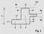
図2は、本願発明に係る水平なフレーム枠の第2の実施形態の断面図を示す。図1の実施形態と同様に、水平なフレーム枠10.2は第1の枠側面11を有し、該枠側面11は、前回と同様に、床面上に固定表面を形成する。枠側面11,12間の間隔が水平なフレーム枠10.2の高さhを定めるように、枠側面11から間隔をあけて配置される別の枠側面12は、枠側面11と実質的に平行に延びている。前回と同様に、枠側面12は、第1の水平な取付面M1を定めている。この場合もやはり、水平なフレーム枠10.2は、実質的に長方形の枠室Pを有する中空枠として組み立てられる。この場合において、枠室Pから土台Sが突出し、該土台Sは、固定表面、すなわち枠側面11と、枠側面11と平行に延びている座面、すなわち枠側面11”と、を有する。垂直に延びている枠側面11’により、固定表面11および座面11”を接合させる。さらに、固定表面11から上方に延びているのが枠側面14であり、該枠側面14はそこから垂直に延びている固定支持部40につながる。該固定支持部40の上側および下側は、さらなる水平な取付面M2およびM3をそれぞれ定めている。固定支持部40は中空枠として形成され、図1の固定支持部30に相当し、枠側面15に結合する。該枠側面15は、枠側面14と実質的に一直線となり、枠側面12に対して垂直につながる。固定表面11が枠室Pの幅を超えて横方向に延びている土台Sが、水平なフレーム枠10.2に特別な安定性を与える。それでもなお、全てのラックの水平なフレーム枠が、図2に示されるように組み立てられているとは限定しなくてもよい;例えば、代わりに、水平なフレーム枠を組み合わせてもよく、例を挙げると、お互いに反対側に位置している図2の2つのフレーム枠10.2、およびそこから垂直に延びている、異なるタイプの、2つのさらなる水平のフレーム枠からベースアセンブリを形成するようにしてもよい。
FIG. 2 shows a cross-sectional view of a second embodiment of a horizontal frame according to the present invention. Similar to the embodiment of FIG. 1, the horizontal frame frame 10.2 has a first
図3は、本願発明に係るベースアセンブリの水平なフレーム枠10.3の第3の実施形態の断面図を示し、該第3の実施形態は図2のフレーム枠10.2の実施形態の変形例である。枠室Pの形状が変更されており、この場合においては、長方形よりも、かえって実質的に切り立って(perpendicular)いる。これを達成するため、図2と異なり、垂直に延びている枠側面14を超えて外に延びることができるように、水平なフレーム枠10.2に対して横方向に枠側面12を延ばしている。その結果、枠側面14と垂直に配置される固定支持部50は、図2の固定支持部40と比較して短く形成される。しかしながら、固定支持部50の上側および下側のそれぞれの水平な取付面M2およびM3は、留め金受け部の適切な追加と共に維持される。座面11”は、さらなる水平な取付面として、同様に維持される。
FIG. 3 shows a cross-sectional view of a third embodiment of a horizontal frame 10.3 of a base assembly according to the present invention, which is a modification of the embodiment of the frame 10.2 of FIG. It is an example. The shape of the frame chamber P has been changed, and in this case, it is substantially perpendicular rather than rectangular. In order to achieve this, unlike FIG. 2, the
水平な取付面M2,M3を設けることは別として、固定支持部20,30,40,50はさらなる機能、例えば、軒樋(特に図1の固定支持部20)や、プッシュオン式のシール材(push-on seals)を受ける封止縁、シール面としての機能を果たすことができる。特に該シール面は、本発明に係るベースアセンブリに基づくスイッチギヤキャビネット同士を一列に並べることを容易にする。
Apart from the provision of the horizontal mounting surfaces M2, M3, the fixed
図4は、本願発明に係るベースアセンブリ用の水平なフレーム枠10.4の第4の実施形態の断面図を示す。水平なフレーム枠10.4は、前回と同様に、単腔の中空枠として形成されるが、枠の斜線Dに対して対称になるように構成される。水平なフレーム枠10.4の固定表面を定めている枠側面11は、図1から図3の実施形態より狭い。これに接合させるのが相対的に短い移行領域14’であり、該移行領域14’は固定支持部60に結合する。該固定支持部60の上側および下側は、水平な取付面M2およびM3をそれぞれ定めている。反対側では、枠側面11が枠側面17’に対して垂直に結合し、それから該枠側面17’に実質的に垂直な固定支持部分18に結合する。該固定支持部分18は、固定支持部70の一部を定めている。枠側面17’および固定支持部分18は、実質的に正方形の横断面を有するアンダーカットを定めており、該横断面をケーブルやリード線などの収納に用いることができる。これは、特にモジュールの連結場所において利点を与え、該モジュールの連結場所においては、固定支持部70が、他の水平な枠の同一タイプまたは同様の固定支持部(例えば、図9に係る水平な枠10.7の固定支持部90)の反対側に位置している。固定支持部70は枠側面16に結合し、それから枠側面12に結合する。枠側面11から枠側面12の間隔は、水平なフレーム枠10.4の高さhを定めている。同様に、枠側面12と垂直に接合する枠側面15’は、水平な取付面M2と垂直に接合する。枠側面15’は、留め金受け部を随意に有してもよい。
FIG. 4 shows a cross-sectional view of a fourth embodiment of a horizontal frame 10.4 for a base assembly according to the present invention. The horizontal frame 10.4 is formed as a single-cavity hollow frame as in the previous case, but is configured to be symmetric with respect to the oblique line D of the frame. The
したがって、本願発明を用い得る水平なフレーム枠の上述した実施形態のすべてにおいて、必要に応じた外側からのベースグループへの連結を含む、取付および支持の極めて幅広い選択肢が設けられる。 Thus, in all of the above-described embodiments of horizontal frame frames that can use the present invention, a very wide range of mounting and support options are provided, including connection to the base group from the outside as required.
図5は、本願発明に係るベースアセンブリ用の水平なフレーム枠10.5の別の実施形態の断面図を示す。前回と同様に、水平なフレーム枠10.5は、枠室Pに接続される土台Sを有する中空枠として組み立てられる。この土台の枠側面11が、図2および図3の実施形態と同様の、拡大された固定表面を提供し、この場合も先回と同様に、該枠側面11に平行な座面11”が設けられ、該座面11”が、ベースアセンブリの内装部品用に利用できる、さらなる水平な取付面M2を定めている。固定表面11および座面11”は、これらから垂直に延びている枠部分11’によりお互いに接続される。垂直な横断面を有する枠室Pを備える水平なフレーム枠10.5であって、土台Sと突起部80の間に凹部82が形成され、例えば、ラックを並べるために使用される平面部位の屈曲部に係合できる。粉末や湿気からの効果的な遮蔽を確保するために突起部80の上方に溝84が導入され、該溝84内に封の挿入、接着接合、注入などが可能である。
FIG. 5 shows a cross-sectional view of another embodiment of a horizontal frame 10.5 for a base assembly according to the present invention. As before, the horizontal frame 10.5 is assembled as a hollow frame having a base S connected to the frame chamber P. The
このフレーム枠の変形例を図6に示す。この中空枠として組み立てられた水平なフレーム枠10.6においても、枠室Pが土台Sに結合し、枠室Pの最も広い幅よりも土台Sの幅が広く、横方向において、枠室Pを超えて両方向に突出している。したがって、土台Sの枠側面11は、図5の実施形態のものに対応する固定表面を備え、固定表面と平行に座面11’が設けられ、該座面は水平な取付面M2を定めている。固定表面11および座面11”は、枠部分11’によりお互いに接続される。座面11”は枠側面16に結合し、該枠側面16は座面11”に対して垂直に延びており、枠側面12へ連なる。該枠側面12は、第1の水平な取付面M1を定めている。第1の枠側面部分19.1は、そこから垂直に延びている枠側面12に隣接する;第1の枠側面部分19.1に隣接しており、そこと垂直に延びているのが第2の枠側面部分19.2であり、第2の枠側面部分19.2に隣接しており、そこに対して斜めに、略135°の角度で延びているのが第3の枠側面部分19.3である。該第3の枠側面部分19.3は、土台Sの上側につながる。その結果、凹部92もここに形成され、平面部分の屈曲部を該凹部に挿入できる。もし封を要望するなら、枠側面部分19.1にシール材を吹き付けてもよい、
A modification of this frame is shown in FIG. Also in the horizontal frame frame 10.6 assembled as a hollow frame, the frame chamber P is coupled to the base S, and the width of the base S is wider than the widest width of the frame chamber P. Projecting in both directions beyond. Therefore, the
図7は、ラックのコーナー部を示し、該ラックにおいて図6の実施形態に係る水平なフレーム枠がベースアセンブリに用いられる。ここでは詳細に説明しないコーナー片120を用いて、2つの水平なフレーム枠10.6が垂直なフレーム枠100へ接続される。周知の実施形態の垂直なフレーム枠やコーナー片が適切である。例示した水平なフレーム枠10.6は、これらがコーナー片120で交わり、お互いが同一平面で隣接するような長さに切断され、特に2つの水平なフレーム枠10.6の水平な取付面M2を一直線上にできるようにする。したがって、水平なフレーム枠10.6の一方から他方への座面11”の連続拡張は、ラックのベース領域の内装部品に用いられることが可能な支持フレームを作り出す。さらに枠側面16において、例示のために、留め金受け部161,162がここに導入される。該留め金受け部161,162はフレーム枠における穴の通常のシステムに相当し、例えば取付レール、シャーシ、ケーブルの配索用の経路、または同様のものなどの内装部品の取り付けに用いることができ、底板に用いられてもよい。
FIG. 7 shows a corner of the rack, in which a horizontal frame according to the embodiment of FIG. 6 is used for the base assembly. Here, two horizontal frame frames 10.6 are connected to the
対応する留め金受け部が設けられる限り、上記枠形状により、また図8および図9に係る枠形状により、これらの内装部品の選択肢もまた提供される。 As long as a corresponding clasp receiving part is provided, the options of these interior parts are also provided by the frame shape and by the frame shape according to FIGS.
図9と共に考慮されるように作成されている図8は、さらなる水平なフレーム枠10.7の斜視図である。該フレーム枠10.7は、フレーム枠の負荷強度が重要な要素である応用において、特に適している。縦方向に枠側面11まで延びている補強用支持体86により、水平なフレーム枠10.7の枠室Pは縦方向に分割され、該枠側面11はフレーム枠10.7の固定表面を形成する。
FIG. 8, created as considered in conjunction with FIG. 9, is a perspective view of a further horizontal frame 10.7. The frame 10.7 is particularly suitable for applications where the load strength of the frame is an important factor. The frame chamber P of the horizontal frame frame 10.7 is divided in the vertical direction by the reinforcing
図9の断面図において、水平なフレーム枠10.7の枠形状をより明確に説明する。枠側面12の枠薄板は、180°折り重なって枠室Pに引き込まれ、枠薄板の二重層で作成された補強用支持体86を生じさせ、枠側面11に支持される。これは、重負荷を枠側面12にかけた時でさえ、確実に枠形状の変形が発生しないようにする働きをする。また、重負荷用に十分利用されるために、M1の取付面を取り付ける選択もまた可能にする。枠側面12に隣接してそこから垂直に延びているのは枠側面15であり、該枠側面15は、固定支持部90につながる。該固定支持部90の上側および下側は、水平に延びている取付面M2およびM3をそれぞれ定めている。図4の実施形態と同様に、取付面M3と、該取付面M3と垂直である枠側面部分17”の間に凹部Aが設けられる。該凹部Aにおいて、ケーブルやライン類を配線してもよい;この場合も同様に、取付面M3に設けられる留め金受け部(図示せず)を用いてこれらのケーブルやラインを固定してもよく、例えば、留め金受け部での係止クリップを用いてもよい。段部14”を経由して枠側面11が枠側面13へと移行し、該枠側面13は水平なフレーム枠10.7の外側を形成する。
In the cross-sectional view of FIG. 9, the frame shape of the horizontal frame 10.7 will be described more clearly. The frame thin plate on the
図10は本願発明に係るベースアセンブリの部分斜視図を示し、図3に係る水平なフレーム枠10.3が使用される。この場合、該フレーム枠10.3とベース板100との組み合わせで、少なくともラックのベース部分180を部分的に覆っている。
FIG. 10 shows a partial perspective view of the base assembly according to the present invention, in which a horizontal frame frame 10.3 according to FIG. 3 is used. In this case, the combination of the frame frame 10.3 and the
ベース板100は屈曲縁102を有し、該屈曲縁102の長さは水平なフレーム枠10.3の枠部分11’の高さに相当する。該水平なフレーム枠10.3は、結果的に固定表面としての枠側面11と同一平面である、全体的な端部となっている。座面11”の留め金受け部での2つのねじ104,106を用いてベース板100を固定し、ベース板100はさらに凹部(図示せず)を有し、該凹部には、ベース板の下方からケーブルを入れることができるようにブラシストリップ108が取り付けられる。したがって、上記例示の方法による、本願発明に係る水平なフレーム枠の構造は、この目的のためのベースフレームやベーストレーを必要とすることなく、ベース板を直接取り付けることができる。
The
図11に図示されるように、ベースパネルやベース板の複数の設計が可能である。ここに図示されたラックの実施形態において、図1の実施形態に係る水平なフレーム枠10.1が使用される。この場合、その固定オプションを有する固定支持部20が使用されるよりは、むしろ取付面M4およびM5(図1)を定めている固定支持部30が使用される。
As shown in FIG. 11, a plurality of designs of the base panel and the base plate are possible. In the rack embodiment illustrated here, a horizontal frame frame 10.1 according to the embodiment of FIG. 1 is used. In this case, rather than the fixed
図11の配置は、いくつかの平面において、どのようにベース板110,120,130が構成され得るかを説明する。複数の屈曲角112,114を有する端部を有する2つの相対する側面が設けられたベース板110は、その自由端を取付面M4において固定され、したがって、ケーブル挿入、および異なるタイプの電力の場合にケーブルを仕切るためにも使用できる空間を形成する。あるいは、取付面M5において平坦な屈曲端を有する、トレー状のさらなるベース板を、いわば“逆さまに”固定してもよく、ベース板同士の間で少なくとも部分的に囲まれた空間を形成する。したがって、支持板としてのベース板110の構造では、設備の変更が可能である。別のベース板120は、一方の自由端において二重の屈曲端122を有し、該一方の自由端は、階段状の隆起表面126へ連なる一重の屈曲端124を有する反対端から、距離を置いて配置される。これは、一重の屈曲端128と組み合わせることで、スライド動作が屈曲端124および128により制限され、摺動自在にベース板130に配置できるベース板120の領域をもたらす。図12および図13の組み合わせによって、より詳細に図示されたこの構成のため、例えば、ベース板120をベース板130上に移動させることにより、ベース板110’とベース板120の間に間隔Lを作り出すことができる。ケーブルをこの間隔Lに入れることができ、その後、間隔Lを非常に小さくし続けることができるよう、ベース板120をベース板110’の方へ移動でき、したがって、ごみや湿気が侵入することを防止できる。
The arrangement of FIG. 11 illustrates how the
図14は、水平なフレーム枠10.1の方へ延びている2つのベース板140,150の組み合わせを示す。該水平なフレーム枠10.1において、これらのベース板はエンドピース160により横方向の移動を防止されており、ベースアセンブリのベース部分180をこれらのベース板が覆っている。ベース板140,150およびエンドピース160は、取付面M4で固定される。ベース板140の異なる位置で固定できる分割用支持体142,144をベース板140は備えており、ベース板140の屈曲端に沿って適切な留め金受け部が設けられることを、該分割用支持体142,144は目的とする。もし、これらの支持体を単にその場所に接続するなら、必要に応じていつでも、分割用支持体142,144を再配置することができ、したがって、例えばスペアケーブルのための、個々の棚エリアを作り出すことができる。
FIG. 14 shows a combination of two
図15の上方で最も明確に示されるように、ベース板140,150は、スナップ係止式で自動ロック式のクランプ部材170,172を用いて固定される。水平なフレーム枠の垂直な枠側面16に設けられた穴のシステムにおいて、クランプ部材170,172が留め金受け部に挿入され、ベース板140,150の屈曲端にある、一方の接触面170’,180’に固定される。これは、工具不要のアッセンブリを可能にし、キャビネットを容易に再構成できるようにする。
As shown most clearly in the upper part of FIG. 15, the
上述の記載、図面および特許請求の範囲で開示された本発明の特徴は、単独でも、あらゆる組み合わせでも、本発明を実施するために不可欠と考慮される。
The features of the invention disclosed in the above description, drawings and claims, either alone or in any combination, are considered essential to the practice of the invention.
Claims (18)
1つ以上の前記水平なフレーム枠(10.2,10.3,10.5,10.6)は、突出している土台(S)を有する枠室(P)を有し、前記土台(S)は固定表面(11)および座面(11”)を有し、
少なくとも前記固定表面(11)は、少なくとも一方の横方向において、枠室(P)の幅を超えて延び、前記固定表面(11)および前記座面(11”)はお互いに平行に延び、
水平な取付面(11”)は前記座面(11”)に位置し、垂直に延びている枠側面(11’)によって前記固定表面(11)および前記座面(11”)をお互いに接続し、
前記水平なフレーム枠(10.6)は中空枠であり、前記水平なフレーム枠(10.6)の前記固定表面(11”)は留め金受け部を有し、
ラックのコーナー部において、前記水平なフレーム枠(10.6)の内の2つを、コーナー片(120)を用いて垂直なフレーム枠(100)に接合させ、前記水平なフレーム枠(10.6)は、これらがコーナー片120で交わり、お互いが同一平面で隣接するような長さに切断され、前記2つの水平なフレーム枠(10.6)の水平な取付面M2をお互いに一直線上にできるようにし、したがって、一方の前記水平なフレーム枠(10.6)の座面(11”)は、他方の前記水平なフレーム枠(10.6)の座面(11”)へ連続拡張し、支持フレームを作り出すことを特徴とするベースアセンブリ。 A base assembly for a rack for a switchgear cabinet having a height h and having a horizontal frame frame surrounding the base portion (180) of the rack, wherein the frame frame is at a first horizontal position at the height h. In a base assembly having a mounting surface (M1), at least one further mounting surface (M2, M3, M4, M5, 11 "arranged at a distance from said first horizontal mounting surface (M1). ) Is provided on or adjacent to the fixed support portion (20, 30, 40, 50, 60, 70, 90, S), and the fixed support portion (20, 30, 40, 50, 60, 70, 90, S) S) is at least partially formed of one or more of the frame frames (10.1, 10.2, 10.3, 10.4, 10.5, 10.6, 10.7), and the base Projecting into part (180),
One or more of the horizontal frame frames (10.2, 10.3, 10.5, 10.6) have a frame chamber (P) with a protruding base (S) and the base (S ) Has a fixed surface (11) and a seating surface (11 "),
At least the fixing surface (11) extends beyond the width of the frame chamber (P) in at least one lateral direction, the fixing surface (11) and the seating surface (11 ″) extend parallel to each other;
A horizontal mounting surface (11 ″) is located on the seat surface (11 ″) and connects the fixed surface (11) and the seat surface (11 ″) to each other by a vertically extending frame side surface (11 ′). And
The horizontal frame (10.6) is a hollow frame, the fixed surface (11 ″) of the horizontal frame (10.6) has a clasp receiving portion;
At the corner of the rack, two of the horizontal frame frames (10.6) are joined to the vertical frame frame (100) using corner pieces (120), and the horizontal frame frame (10. 6), these are intersected at the corner pieces 120 and cut to such a length that they are adjacent to each other on the same plane, and the horizontal mounting surfaces M2 of the two horizontal frame frames (10.6) are aligned with each other. Therefore, the seating surface (11 ″) of one of the horizontal frame frames (10.6) is continuously extended to the seating surface (11 ″) of the other horizontal frame frame (10.6). And producing a support frame.
Applications Claiming Priority (3)
| Application Number | Priority Date | Filing Date | Title |
|---|---|---|---|
| DE102014101405.7A DE102014101405A1 (en) | 2014-02-05 | 2014-02-05 | Floor assembly for the frame of a cabinet |
| DE102014101405.7 | 2014-02-05 | ||
| PCT/DE2015/100035 WO2015117598A1 (en) | 2014-02-05 | 2015-01-28 | Bottom assembly for the frame of a switch cabinet |
Publications (2)
| Publication Number | Publication Date |
|---|---|
| JP2017507634A JP2017507634A (en) | 2017-03-16 |
| JP6330050B2 true JP6330050B2 (en) | 2018-05-23 |
Family
ID=52574000
Family Applications (1)
| Application Number | Title | Priority Date | Filing Date |
|---|---|---|---|
| JP2016546509A Active JP6330050B2 (en) | 2014-02-05 | 2015-01-28 | Switch base rack base assembly |
Country Status (16)
| Country | Link |
|---|---|
| US (1) | US9871353B2 (en) |
| EP (1) | EP3103171B1 (en) |
| JP (1) | JP6330050B2 (en) |
| KR (1) | KR102204540B1 (en) |
| CN (1) | CN106063062B (en) |
| BR (1) | BR112016017519B1 (en) |
| CA (1) | CA2937586C (en) |
| DE (1) | DE102014101405A1 (en) |
| ES (1) | ES2754505T3 (en) |
| HU (1) | HUE047623T2 (en) |
| MX (1) | MX2016009260A (en) |
| PL (1) | PL3103171T3 (en) |
| RU (1) | RU2665313C1 (en) |
| UA (1) | UA118779C2 (en) |
| WO (1) | WO2015117598A1 (en) |
| ZA (1) | ZA201604771B (en) |
Families Citing this family (19)
| Publication number | Priority date | Publication date | Assignee | Title |
|---|---|---|---|---|
| DE102015121192B4 (en) | 2015-12-04 | 2019-09-19 | Rittal Gmbh & Co. Kg | Frame for a control cabinet |
| DE102015121193B4 (en) * | 2015-12-04 | 2017-07-13 | Rittal Gmbh & Co. Kg | Framework for a control cabinet arrangement |
| DE102017108320B4 (en) | 2016-06-27 | 2019-01-10 | Rittal Gmbh & Co. Kg | Flat part holder for fixing a flat part to a frame of a control cabinet and a corresponding control cabinet |
| DE102016117378B3 (en) | 2016-09-15 | 2017-05-18 | Rittal Gmbh & Co. Kg | Hinge arrangement for a control cabinet |
| DE102016117393A1 (en) | 2016-09-15 | 2018-03-15 | Rittal Gmbh & Co. Kg | Control cabinet with a frame and an interior component and a corresponding control cabinet assembly and a corresponding interior component |
| CN108012471A (en) * | 2016-10-31 | 2018-05-08 | 鸿富锦精密电子(天津)有限公司 | Server column |
| DE102016123230B3 (en) | 2016-12-01 | 2017-11-16 | Rittal Gmbh & Co. Kg | Hinge arrangement for a control cabinet housing and a corresponding control cabinet housing |
| DE102016124078B3 (en) | 2016-12-12 | 2018-05-09 | Rittal Gmbh & Co. Kg | Connecting arrangement for the connection of two control cabinet frame racks |
| DE102017108335B4 (en) | 2017-04-19 | 2019-01-03 | Rittal Gmbh & Co. Kg | Mounting arrangement and a corresponding cabinet housing |
| DE102017108523B4 (en) * | 2017-04-21 | 2019-01-03 | Rittal Gmbh & Co. Kg | Mounting plate arrangement for a control cabinet |
| DE102017108518B4 (en) | 2017-04-21 | 2019-01-03 | Rittal Gmbh & Co. Kg | Mounting plate assembly and a corresponding method |
| DE102017114385B4 (en) * | 2017-06-28 | 2021-06-24 | Rittal Gmbh & Co. Kg | Control cabinet frame with locked base frame |
| DE102017127576A1 (en) | 2017-11-22 | 2019-05-23 | Rittal Gmbh & Co. Kg | Closing device for a control cabinet and a corresponding control cabinet |
| DE202018100613U1 (en) | 2018-02-05 | 2018-02-14 | Rittal Gmbh & Co. Kg | Arrangement with two interconnected via a bay connector control cabinet frame racks |
| DE102019104151A1 (en) * | 2019-02-19 | 2020-08-20 | Rittal Gmbh & Co. Kg | Control cabinet with at least one brush strip for the conductor lead-through |
| BR102019010955B1 (en) * | 2019-05-28 | 2023-04-11 | Melquisedec Francisquini | STRUCTURAL PROFILE FOR ELECTRICAL CABINETS |
| CN112135473B (en) * | 2020-09-06 | 2021-10-26 | 苏州浪潮智能科技有限公司 | Modular transportation cabinet |
| CN113013741B (en) * | 2021-04-06 | 2023-07-25 | 北京中科中电电力工程管理有限公司 | Switch cabinet and installation process thereof |
| CN114614176A (en) * | 2022-03-25 | 2022-06-10 | 中创新航科技股份有限公司 | Energy storage rack |
Family Cites Families (25)
| Publication number | Priority date | Publication date | Assignee | Title |
|---|---|---|---|---|
| DE3731547C3 (en) * | 1987-09-19 | 1995-05-04 | Loh Kg Rittal Werk | switch cabinet |
| US5004107A (en) * | 1989-05-05 | 1991-04-02 | Hendry Mechanical Works | Earthquake braced racks |
| US5380083A (en) * | 1991-11-27 | 1995-01-10 | Federal-Hoffman, Inc. | Multifaceted modular enclosure frame with integral sub-panel guide system |
| DE4140072A1 (en) | 1991-12-05 | 1993-06-09 | Rittal-Werk Rudolf Loh Gmbh & Co Kg, 6348 Herborn, De | Switch cabinet with frame of assembled members completed by wall elements and door - has mounting plate fixable at frame parallel to rear wall and carries slide pieces at its underside with guide elements |
| DE4207281C1 (en) * | 1992-03-07 | 1993-04-29 | Rittal-Werk Rudolf Loh Gmbh & Co Kg, 6348 Herborn, De | |
| IT1265407B1 (en) * | 1993-12-17 | 1996-11-22 | Italtel Spa | SEALED METAL CABINET, IN PARTICULAR FOR THE HOUSING OF ELECTRIC AND ELECTRONIC EQUIPMENT |
| DE4446223C1 (en) * | 1994-12-23 | 1996-04-04 | Loh Kg Rittal Werk | Electrical switch appts. housing |
| DE29509555U1 (en) | 1995-06-10 | 1995-08-24 | Dessauer Schaltschrankbau Gmbh | Control cabinet with mounting plate as a single or modular cabinet |
| FI961735A0 (en) * | 1996-04-22 | 1996-04-22 | Control Ab Oy Ensto | Moduluppbyggd kaopa |
| DE19647814C2 (en) * | 1996-11-19 | 1999-06-02 | Loh Kg Rittal Werk | switch cabinet |
| DE19730430C2 (en) * | 1997-07-16 | 1999-07-15 | Loh Kg Rittal Werk | Frame for a control cabinet |
| DE19813222C1 (en) | 1998-03-26 | 1999-11-25 | Loh Kg Rittal Werk | Frame for a control cabinet |
| IT249686Y1 (en) * | 2000-01-05 | 2003-05-28 | Cost El S P A | PROFILE FOR FRAMES OF WINDOW CABINETS OR SIMILAR |
| JP3628229B2 (en) * | 2000-03-09 | 2005-03-09 | 日東工業株式会社 | Frame structure of electrical equipment storage box |
| US20050193930A1 (en) * | 2002-02-16 | 2005-09-08 | Marc Hartel | Frame profile section |
| BR0202231A (en) * | 2002-06-06 | 2004-04-27 | Melquisedec Francisquini | Improvement in metallic profile for composition of structures for mounting electrical panels |
| US7498512B2 (en) * | 2006-03-13 | 2009-03-03 | Panduit Corp. | Network cabinet |
| KR100959679B1 (en) * | 2007-10-08 | 2010-05-26 | 주식회사 럭스코 | Marine main switchboard |
| RU2384285C2 (en) * | 2008-05-12 | 2010-03-20 | Андрей Витальевич Машкин | Frame structure of distribution cabinet |
| KR101200761B1 (en) * | 2010-06-15 | 2012-11-13 | 오성기전주식회사 | Apparatus for fabricating panel for high and low distributing board, distributing panel and motor control board |
| DE102010033319A1 (en) * | 2010-08-04 | 2012-02-09 | Protektorwerk Florenz Maisch Gmbh & Co. Kg | Cabinet profile, in particular control cabinet profile and cabinet, in particular control cabinet |
| DE102010035789A1 (en) * | 2010-08-30 | 2012-03-01 | C E S Control Enclosure Systems Gmbh | Cabinet frame |
| CN202007500U (en) * | 2011-03-29 | 2011-10-12 | 高刚 | Concealed gusset plate profile and gusset plate connecting structure |
| CN202220394U (en) * | 2011-09-01 | 2012-05-16 | 谢湖滨 | Light partition wall |
| CN202918622U (en) * | 2012-11-16 | 2013-05-01 | 无锡康贝电子设备有限公司 | Column section bar for rack framework |
-
2014
- 2014-02-05 DE DE102014101405.7A patent/DE102014101405A1/en active Pending
-
2015
- 2015-01-28 ES ES15705901T patent/ES2754505T3/en active Active
- 2015-01-28 PL PL15705901T patent/PL3103171T3/en unknown
- 2015-01-28 CA CA2937586A patent/CA2937586C/en active Active
- 2015-01-28 WO PCT/DE2015/100035 patent/WO2015117598A1/en active Application Filing
- 2015-01-28 CN CN201580007453.XA patent/CN106063062B/en active Active
- 2015-01-28 UA UAA201609152A patent/UA118779C2/en unknown
- 2015-01-28 RU RU2016135689A patent/RU2665313C1/en active
- 2015-01-28 US US15/116,754 patent/US9871353B2/en active Active
- 2015-01-28 KR KR1020167021581A patent/KR102204540B1/en active IP Right Grant
- 2015-01-28 EP EP15705901.5A patent/EP3103171B1/en active Active
- 2015-01-28 JP JP2016546509A patent/JP6330050B2/en active Active
- 2015-01-28 BR BR112016017519-0A patent/BR112016017519B1/en active IP Right Grant
- 2015-01-28 MX MX2016009260A patent/MX2016009260A/en active IP Right Grant
- 2015-01-28 HU HUE15705901A patent/HUE047623T2/en unknown
-
2016
- 2016-07-12 ZA ZA2016/04771A patent/ZA201604771B/en unknown
Also Published As
| Publication number | Publication date |
|---|---|
| KR102204540B1 (en) | 2021-01-20 |
| PL3103171T3 (en) | 2020-01-31 |
| ZA201604771B (en) | 2017-09-27 |
| KR20160117473A (en) | 2016-10-10 |
| DE102014101405A1 (en) | 2015-08-06 |
| MX2016009260A (en) | 2016-11-11 |
| HUE047623T2 (en) | 2020-05-28 |
| US9871353B2 (en) | 2018-01-16 |
| JP2017507634A (en) | 2017-03-16 |
| EP3103171B1 (en) | 2019-09-18 |
| EP3103171A1 (en) | 2016-12-14 |
| CN106063062B (en) | 2019-11-08 |
| WO2015117598A1 (en) | 2015-08-13 |
| ES2754505T3 (en) | 2020-04-17 |
| BR112016017519B1 (en) | 2023-03-07 |
| RU2665313C1 (en) | 2018-08-29 |
| BR112016017519A2 (en) | 2017-08-08 |
| CA2937586A1 (en) | 2015-08-13 |
| US20160352082A1 (en) | 2016-12-01 |
| CA2937586C (en) | 2018-10-30 |
| CN106063062A (en) | 2016-10-26 |
| UA118779C2 (en) | 2019-03-11 |
Similar Documents
| Publication | Publication Date | Title |
|---|---|---|
| JP6330050B2 (en) | Switch base rack base assembly | |
| US5326162A (en) | Rack for a control cabinet | |
| JP2021023781A (en) | Slide rail assembly | |
| JP7164400B2 (en) | Furniture with top plate | |
| JP2018050661A (en) | Side frame structure of rack | |
| JP5879137B2 (en) | Desk equipment | |
| KR101075920B1 (en) | Frame Apparatus for Wall | |
| JP5305450B2 (en) | Frame cabinet | |
| JP6714345B2 (en) | table | |
| JP6260012B2 (en) | Electrical equipment storage box | |
| CN209799534U (en) | self-locking fastening splicing structure of storage rack box body | |
| KR20140004785U (en) | Structure of face to face desk | |
| KR20120133337A (en) | Desk | |
| US10827832B2 (en) | Furnishing item comprising an integrated harness assembly | |
| US6189988B1 (en) | Switching cabinet | |
| KR20120028417A (en) | A section panel for collection box and section apparatus for the same | |
| JP6732376B2 (en) | Base structure | |
| KR20160004426U (en) | Wall Shelf | |
| JP6359840B2 (en) | Building unit transportation method, building unit, unit building | |
| JP3136238U (en) | Complex unit furniture | |
| JP6567862B2 (en) | Mounting structure of building material having unevenness adjustment function and mounting structure of storage unit using the building material | |
| JP6591154B2 (en) | Collection of desks | |
| JP3736623B2 (en) | Goods storage equipment | |
| JP6169827B2 (en) | Living room floor structure | |
| JP2015055135A (en) | Panel fitting tool and panel fitting structure |
Legal Events
| Date | Code | Title | Description |
|---|---|---|---|
| A621 | Written request for application examination |
Free format text: JAPANESE INTERMEDIATE CODE: A621 Effective date: 20170508 |
|
| A977 | Report on retrieval |
Free format text: JAPANESE INTERMEDIATE CODE: A971007 Effective date: 20180208 |
|
| A131 | Notification of reasons for refusal |
Free format text: JAPANESE INTERMEDIATE CODE: A131 Effective date: 20180220 |
|
| A521 | Request for written amendment filed |
Free format text: JAPANESE INTERMEDIATE CODE: A523 Effective date: 20180301 |
|
| TRDD | Decision of grant or rejection written | ||
| A01 | Written decision to grant a patent or to grant a registration (utility model) |
Free format text: JAPANESE INTERMEDIATE CODE: A01 Effective date: 20180403 |
|
| A61 | First payment of annual fees (during grant procedure) |
Free format text: JAPANESE INTERMEDIATE CODE: A61 Effective date: 20180423 |
|
| R150 | Certificate of patent or registration of utility model |
Ref document number: 6330050 Country of ref document: JP Free format text: JAPANESE INTERMEDIATE CODE: R150 |
|
| R250 | Receipt of annual fees |
Free format text: JAPANESE INTERMEDIATE CODE: R250 |
|
| R250 | Receipt of annual fees |
Free format text: JAPANESE INTERMEDIATE CODE: R250 |
|
| R250 | Receipt of annual fees |
Free format text: JAPANESE INTERMEDIATE CODE: R250 |