JP6326582B2 - Microchannel chip for particle separation, particle separation system using the chip, and particle separation method - Google Patents
Microchannel chip for particle separation, particle separation system using the chip, and particle separation method Download PDFInfo
- Publication number
- JP6326582B2 JP6326582B2 JP2014542131A JP2014542131A JP6326582B2 JP 6326582 B2 JP6326582 B2 JP 6326582B2 JP 2014542131 A JP2014542131 A JP 2014542131A JP 2014542131 A JP2014542131 A JP 2014542131A JP 6326582 B2 JP6326582 B2 JP 6326582B2
- Authority
- JP
- Japan
- Prior art keywords
- fine particles
- capture site
- flow path
- chip
- particle separation
- Prior art date
- Legal status (The legal status is an assumption and is not a legal conclusion. Google has not performed a legal analysis and makes no representation as to the accuracy of the status listed.)
- Active
Links
- 238000000926 separation method Methods 0.000 title claims description 127
- 239000002245 particle Substances 0.000 title claims description 58
- 239000007788 liquid Substances 0.000 claims description 206
- 239000010419 fine particle Substances 0.000 claims description 156
- 239000000523 sample Substances 0.000 claims description 106
- 210000005266 circulating tumour cell Anatomy 0.000 claims description 90
- 238000000034 method Methods 0.000 claims description 48
- 239000011859 microparticle Substances 0.000 claims description 43
- 230000005499 meniscus Effects 0.000 claims description 42
- 210000000601 blood cell Anatomy 0.000 claims description 21
- 239000012488 sample solution Substances 0.000 claims description 17
- 239000000758 substrate Substances 0.000 claims description 10
- 238000005406 washing Methods 0.000 claims description 8
- 230000005684 electric field Effects 0.000 claims description 7
- 239000012530 fluid Substances 0.000 claims description 6
- 239000000463 material Substances 0.000 claims description 6
- 230000008569 process Effects 0.000 claims description 3
- 239000013618 particulate matter Substances 0.000 claims 2
- 230000000149 penetrating effect Effects 0.000 claims 1
- 210000004369 blood Anatomy 0.000 description 43
- 239000008280 blood Substances 0.000 description 43
- 210000004027 cell Anatomy 0.000 description 27
- 239000011324 bead Substances 0.000 description 16
- 210000004881 tumor cell Anatomy 0.000 description 16
- 238000001514 detection method Methods 0.000 description 14
- 239000004793 Polystyrene Substances 0.000 description 13
- 229920002223 polystyrene Polymers 0.000 description 13
- 238000002474 experimental method Methods 0.000 description 12
- 206010028980 Neoplasm Diseases 0.000 description 11
- 201000011510 cancer Diseases 0.000 description 11
- 238000010586 diagram Methods 0.000 description 10
- 238000012545 processing Methods 0.000 description 10
- 239000004205 dimethyl polysiloxane Substances 0.000 description 9
- 229920000435 poly(dimethylsiloxane) Polymers 0.000 description 9
- VYZAMTAEIAYCRO-UHFFFAOYSA-N Chromium Chemical compound [Cr] VYZAMTAEIAYCRO-UHFFFAOYSA-N 0.000 description 8
- 239000000243 solution Substances 0.000 description 8
- XUIMIQQOPSSXEZ-UHFFFAOYSA-N Silicon Chemical compound [Si] XUIMIQQOPSSXEZ-UHFFFAOYSA-N 0.000 description 6
- 238000011161 development Methods 0.000 description 6
- 239000011521 glass Substances 0.000 description 6
- 210000000265 leukocyte Anatomy 0.000 description 6
- 238000002360 preparation method Methods 0.000 description 6
- 229910052710 silicon Inorganic materials 0.000 description 6
- 239000010703 silicon Substances 0.000 description 6
- 239000000725 suspension Substances 0.000 description 6
- 102000018651 Epithelial Cell Adhesion Molecule Human genes 0.000 description 5
- 108010066687 Epithelial Cell Adhesion Molecule Proteins 0.000 description 5
- 210000003743 erythrocyte Anatomy 0.000 description 5
- CSCPPACGZOOCGX-UHFFFAOYSA-N Acetone Chemical compound CC(C)=O CSCPPACGZOOCGX-UHFFFAOYSA-N 0.000 description 4
- LFQSCWFLJHTTHZ-UHFFFAOYSA-N Ethanol Chemical compound CCO LFQSCWFLJHTTHZ-UHFFFAOYSA-N 0.000 description 4
- LOKCTEFSRHRXRJ-UHFFFAOYSA-I dipotassium trisodium dihydrogen phosphate hydrogen phosphate dichloride Chemical compound P(=O)(O)(O)[O-].[K+].P(=O)(O)([O-])[O-].[Na+].[Na+].[Cl-].[K+].[Cl-].[Na+] LOKCTEFSRHRXRJ-UHFFFAOYSA-I 0.000 description 4
- 238000004519 manufacturing process Methods 0.000 description 4
- 239000002953 phosphate buffered saline Substances 0.000 description 4
- 229920002120 photoresistant polymer Polymers 0.000 description 4
- 229910021642 ultra pure water Inorganic materials 0.000 description 4
- 239000012498 ultrapure water Substances 0.000 description 4
- 238000011144 upstream manufacturing Methods 0.000 description 4
- XLYOFNOQVPJJNP-UHFFFAOYSA-N water Substances O XLYOFNOQVPJJNP-UHFFFAOYSA-N 0.000 description 4
- 208000005718 Stomach Neoplasms Diseases 0.000 description 3
- 230000008859 change Effects 0.000 description 3
- 229910052804 chromium Inorganic materials 0.000 description 3
- 239000011651 chromium Substances 0.000 description 3
- 239000012141 concentrate Substances 0.000 description 3
- 206010017758 gastric cancer Diseases 0.000 description 3
- 238000002955 isolation Methods 0.000 description 3
- 239000006249 magnetic particle Substances 0.000 description 3
- 239000012528 membrane Substances 0.000 description 3
- 208000037819 metastatic cancer Diseases 0.000 description 3
- 208000011575 metastatic malignant neoplasm Diseases 0.000 description 3
- 206010061289 metastatic neoplasm Diseases 0.000 description 3
- 239000005022 packaging material Substances 0.000 description 3
- 238000000206 photolithography Methods 0.000 description 3
- 238000009832 plasma treatment Methods 0.000 description 3
- 239000004417 polycarbonate Substances 0.000 description 3
- -1 polydimethylsiloxane Polymers 0.000 description 3
- 238000010186 staining Methods 0.000 description 3
- 201000011549 stomach cancer Diseases 0.000 description 3
- 229920000742 Cotton Polymers 0.000 description 2
- 229910005540 GaP Inorganic materials 0.000 description 2
- 239000004698 Polyethylene Substances 0.000 description 2
- 241001481789 Rupicapra Species 0.000 description 2
- 238000004458 analytical method Methods 0.000 description 2
- 230000015572 biosynthetic process Effects 0.000 description 2
- 238000004140 cleaning Methods 0.000 description 2
- 238000005520 cutting process Methods 0.000 description 2
- 238000003745 diagnosis Methods 0.000 description 2
- 238000005530 etching Methods 0.000 description 2
- 238000011156 evaluation Methods 0.000 description 2
- 239000004744 fabric Substances 0.000 description 2
- 238000001914 filtration Methods 0.000 description 2
- HZXMRANICFIONG-UHFFFAOYSA-N gallium phosphide Chemical compound [Ga]#P HZXMRANICFIONG-UHFFFAOYSA-N 0.000 description 2
- 238000007689 inspection Methods 0.000 description 2
- 230000001394 metastastic effect Effects 0.000 description 2
- 230000003287 optical effect Effects 0.000 description 2
- 210000005259 peripheral blood Anatomy 0.000 description 2
- 239000011886 peripheral blood Substances 0.000 description 2
- 230000002093 peripheral effect Effects 0.000 description 2
- 239000004033 plastic Substances 0.000 description 2
- 229920003023 plastic Polymers 0.000 description 2
- 229920003229 poly(methyl methacrylate) Polymers 0.000 description 2
- 229920000515 polycarbonate Polymers 0.000 description 2
- 229920000036 polyvinylpyrrolidone Polymers 0.000 description 2
- 239000001267 polyvinylpyrrolidone Substances 0.000 description 2
- 235000013855 polyvinylpyrrolidone Nutrition 0.000 description 2
- 238000011084 recovery Methods 0.000 description 2
- 238000011160 research Methods 0.000 description 2
- 239000004065 semiconductor Substances 0.000 description 2
- 230000008685 targeting Effects 0.000 description 2
- JBRZTFJDHDCESZ-UHFFFAOYSA-N AsGa Chemical compound [As]#[Ga] JBRZTFJDHDCESZ-UHFFFAOYSA-N 0.000 description 1
- 206010006187 Breast cancer Diseases 0.000 description 1
- 208000026310 Breast neoplasm Diseases 0.000 description 1
- 201000009030 Carcinoma Diseases 0.000 description 1
- 208000005443 Circulating Neoplastic Cells Diseases 0.000 description 1
- 229910002601 GaN Inorganic materials 0.000 description 1
- 229910001218 Gallium arsenide Inorganic materials 0.000 description 1
- JMASRVWKEDWRBT-UHFFFAOYSA-N Gallium nitride Chemical compound [Ga]#N JMASRVWKEDWRBT-UHFFFAOYSA-N 0.000 description 1
- 238000002738 Giemsa staining Methods 0.000 description 1
- 102000011782 Keratins Human genes 0.000 description 1
- 108010076876 Keratins Proteins 0.000 description 1
- 239000004677 Nylon Substances 0.000 description 1
- 239000004809 Teflon Substances 0.000 description 1
- 229920006362 Teflon® Polymers 0.000 description 1
- 239000007983 Tris buffer Substances 0.000 description 1
- 102000004142 Trypsin Human genes 0.000 description 1
- 108090000631 Trypsin Proteins 0.000 description 1
- 238000009825 accumulation Methods 0.000 description 1
- NIXOWILDQLNWCW-UHFFFAOYSA-N acrylic acid group Chemical group C(C=C)(=O)O NIXOWILDQLNWCW-UHFFFAOYSA-N 0.000 description 1
- 239000000427 antigen Substances 0.000 description 1
- 102000036639 antigens Human genes 0.000 description 1
- 108091007433 antigens Proteins 0.000 description 1
- 238000013459 approach Methods 0.000 description 1
- 230000008901 benefit Effects 0.000 description 1
- 210000004204 blood vessel Anatomy 0.000 description 1
- 210000001124 body fluid Anatomy 0.000 description 1
- 239000010839 body fluid Substances 0.000 description 1
- 239000007853 buffer solution Substances 0.000 description 1
- 239000012930 cell culture fluid Substances 0.000 description 1
- 239000002771 cell marker Substances 0.000 description 1
- 239000012459 cleaning agent Substances 0.000 description 1
- 230000009089 cytolysis Effects 0.000 description 1
- 210000000805 cytoplasm Anatomy 0.000 description 1
- 238000000151 deposition Methods 0.000 description 1
- 239000012470 diluted sample Substances 0.000 description 1
- 238000001035 drying Methods 0.000 description 1
- 230000012202 endocytosis Effects 0.000 description 1
- 238000005516 engineering process Methods 0.000 description 1
- 210000002919 epithelial cell Anatomy 0.000 description 1
- 238000007687 exposure technique Methods 0.000 description 1
- 238000000684 flow cytometry Methods 0.000 description 1
- MHMNJMPURVTYEJ-UHFFFAOYSA-N fluorescein-5-isothiocyanate Chemical compound O1C(=O)C2=CC(N=C=S)=CC=C2C21C1=CC=C(O)C=C1OC1=CC(O)=CC=C21 MHMNJMPURVTYEJ-UHFFFAOYSA-N 0.000 description 1
- 239000007850 fluorescent dye Substances 0.000 description 1
- 230000005484 gravity Effects 0.000 description 1
- 230000036541 health Effects 0.000 description 1
- 239000000017 hydrogel Substances 0.000 description 1
- 230000002209 hydrophobic effect Effects 0.000 description 1
- 125000002887 hydroxy group Chemical group [H]O* 0.000 description 1
- 238000007654 immersion Methods 0.000 description 1
- 238000003364 immunohistochemistry Methods 0.000 description 1
- 238000012744 immunostaining Methods 0.000 description 1
- 238000001746 injection moulding Methods 0.000 description 1
- 230000003834 intracellular effect Effects 0.000 description 1
- 150000002500 ions Chemical class 0.000 description 1
- 210000005033 mesothelial cell Anatomy 0.000 description 1
- 238000002156 mixing Methods 0.000 description 1
- 230000000877 morphologic effect Effects 0.000 description 1
- 230000035772 mutation Effects 0.000 description 1
- 229920001778 nylon Polymers 0.000 description 1
- 239000003330 peritoneal dialysis fluid Substances 0.000 description 1
- 239000011941 photocatalyst Substances 0.000 description 1
- 239000012994 photoredox catalyst Substances 0.000 description 1
- 230000010287 polarization Effects 0.000 description 1
- 229920000573 polyethylene Polymers 0.000 description 1
- 239000004926 polymethyl methacrylate Substances 0.000 description 1
- 239000011148 porous material Substances 0.000 description 1
- 238000004393 prognosis Methods 0.000 description 1
- 239000011347 resin Substances 0.000 description 1
- 229920005989 resin Polymers 0.000 description 1
- 229910052594 sapphire Inorganic materials 0.000 description 1
- 239000010980 sapphire Substances 0.000 description 1
- 210000002966 serum Anatomy 0.000 description 1
- HBMJWWWQQXIZIP-UHFFFAOYSA-N silicon carbide Chemical compound [Si+]#[C-] HBMJWWWQQXIZIP-UHFFFAOYSA-N 0.000 description 1
- 229910010271 silicon carbide Inorganic materials 0.000 description 1
- 239000004094 surface-active agent Substances 0.000 description 1
- 230000001225 therapeutic effect Effects 0.000 description 1
- 238000012546 transfer Methods 0.000 description 1
- LENZDBCJOHFCAS-UHFFFAOYSA-N tris Chemical compound OCC(N)(CO)CO LENZDBCJOHFCAS-UHFFFAOYSA-N 0.000 description 1
- 239000012588 trypsin Substances 0.000 description 1
- 239000000439 tumor marker Substances 0.000 description 1
- 229940121358 tyrosine kinase inhibitor Drugs 0.000 description 1
- 239000005483 tyrosine kinase inhibitor Substances 0.000 description 1
- 150000004917 tyrosine kinase inhibitor derivatives Chemical class 0.000 description 1
Images


Classifications
-
- B—PERFORMING OPERATIONS; TRANSPORTING
- B01—PHYSICAL OR CHEMICAL PROCESSES OR APPARATUS IN GENERAL
- B01L—CHEMICAL OR PHYSICAL LABORATORY APPARATUS FOR GENERAL USE
- B01L3/00—Containers or dishes for laboratory use, e.g. laboratory glassware; Droppers
- B01L3/50—Containers for the purpose of retaining a material to be analysed, e.g. test tubes
- B01L3/502—Containers for the purpose of retaining a material to be analysed, e.g. test tubes with fluid transport, e.g. in multi-compartment structures
- B01L3/5027—Containers for the purpose of retaining a material to be analysed, e.g. test tubes with fluid transport, e.g. in multi-compartment structures by integrated microfluidic structures, i.e. dimensions of channels and chambers are such that surface tension forces are important, e.g. lab-on-a-chip
- B01L3/502753—Containers for the purpose of retaining a material to be analysed, e.g. test tubes with fluid transport, e.g. in multi-compartment structures by integrated microfluidic structures, i.e. dimensions of channels and chambers are such that surface tension forces are important, e.g. lab-on-a-chip characterised by bulk separation arrangements on lab-on-a-chip devices, e.g. for filtration or centrifugation
-
- G—PHYSICS
- G01—MEASURING; TESTING
- G01N—INVESTIGATING OR ANALYSING MATERIALS BY DETERMINING THEIR CHEMICAL OR PHYSICAL PROPERTIES
- G01N1/00—Sampling; Preparing specimens for investigation
- G01N1/02—Devices for withdrawing samples
- G01N1/04—Devices for withdrawing samples in the solid state, e.g. by cutting
-
- G—PHYSICS
- G01—MEASURING; TESTING
- G01N—INVESTIGATING OR ANALYSING MATERIALS BY DETERMINING THEIR CHEMICAL OR PHYSICAL PROPERTIES
- G01N1/00—Sampling; Preparing specimens for investigation
- G01N1/28—Preparing specimens for investigation including physical details of (bio-)chemical methods covered elsewhere, e.g. G01N33/50, C12Q
-
- G—PHYSICS
- G01—MEASURING; TESTING
- G01N—INVESTIGATING OR ANALYSING MATERIALS BY DETERMINING THEIR CHEMICAL OR PHYSICAL PROPERTIES
- G01N15/00—Investigating characteristics of particles; Investigating permeability, pore-volume, or surface-area of porous materials
- G01N15/10—Investigating individual particles
- G01N15/14—Electro-optical investigation, e.g. flow cytometers
- G01N15/1434—Electro-optical investigation, e.g. flow cytometers using an analyser being characterised by its optical arrangement
-
- G—PHYSICS
- G01—MEASURING; TESTING
- G01N—INVESTIGATING OR ANALYSING MATERIALS BY DETERMINING THEIR CHEMICAL OR PHYSICAL PROPERTIES
- G01N33/00—Investigating or analysing materials by specific methods not covered by groups G01N1/00 - G01N31/00
- G01N33/48—Biological material, e.g. blood, urine; Haemocytometers
- G01N33/483—Physical analysis of biological material
- G01N33/487—Physical analysis of biological material of liquid biological material
- G01N33/49—Blood
- G01N33/491—Blood by separating the blood components
-
- G—PHYSICS
- G01—MEASURING; TESTING
- G01N—INVESTIGATING OR ANALYSING MATERIALS BY DETERMINING THEIR CHEMICAL OR PHYSICAL PROPERTIES
- G01N35/00—Automatic analysis not limited to methods or materials provided for in any single one of groups G01N1/00 - G01N33/00; Handling materials therefor
- G01N35/08—Automatic analysis not limited to methods or materials provided for in any single one of groups G01N1/00 - G01N33/00; Handling materials therefor using a stream of discrete samples flowing along a tube system, e.g. flow injection analysis
-
- B—PERFORMING OPERATIONS; TRANSPORTING
- B01—PHYSICAL OR CHEMICAL PROCESSES OR APPARATUS IN GENERAL
- B01L—CHEMICAL OR PHYSICAL LABORATORY APPARATUS FOR GENERAL USE
- B01L2200/00—Solutions for specific problems relating to chemical or physical laboratory apparatus
- B01L2200/06—Fluid handling related problems
- B01L2200/0647—Handling flowable solids, e.g. microscopic beads, cells, particles
- B01L2200/0652—Sorting or classification of particles or molecules
-
- B—PERFORMING OPERATIONS; TRANSPORTING
- B01—PHYSICAL OR CHEMICAL PROCESSES OR APPARATUS IN GENERAL
- B01L—CHEMICAL OR PHYSICAL LABORATORY APPARATUS FOR GENERAL USE
- B01L2200/00—Solutions for specific problems relating to chemical or physical laboratory apparatus
- B01L2200/06—Fluid handling related problems
- B01L2200/0647—Handling flowable solids, e.g. microscopic beads, cells, particles
- B01L2200/0668—Trapping microscopic beads
-
- B—PERFORMING OPERATIONS; TRANSPORTING
- B01—PHYSICAL OR CHEMICAL PROCESSES OR APPARATUS IN GENERAL
- B01L—CHEMICAL OR PHYSICAL LABORATORY APPARATUS FOR GENERAL USE
- B01L2300/00—Additional constructional details
- B01L2300/08—Geometry, shape and general structure
- B01L2300/0809—Geometry, shape and general structure rectangular shaped
- B01L2300/0816—Cards, e.g. flat sample carriers usually with flow in two horizontal directions
-
- B—PERFORMING OPERATIONS; TRANSPORTING
- B01—PHYSICAL OR CHEMICAL PROCESSES OR APPARATUS IN GENERAL
- B01L—CHEMICAL OR PHYSICAL LABORATORY APPARATUS FOR GENERAL USE
- B01L2300/00—Additional constructional details
- B01L2300/08—Geometry, shape and general structure
- B01L2300/0861—Configuration of multiple channels and/or chambers in a single devices
- B01L2300/0864—Configuration of multiple channels and/or chambers in a single devices comprising only one inlet and multiple receiving wells, e.g. for separation, splitting
-
- B—PERFORMING OPERATIONS; TRANSPORTING
- B01—PHYSICAL OR CHEMICAL PROCESSES OR APPARATUS IN GENERAL
- B01L—CHEMICAL OR PHYSICAL LABORATORY APPARATUS FOR GENERAL USE
- B01L2400/00—Moving or stopping fluids
- B01L2400/08—Regulating or influencing the flow resistance
- B01L2400/084—Passive control of flow resistance
- B01L2400/086—Passive control of flow resistance using baffles or other fixed flow obstructions
-
- G01N15/149—
-
- G—PHYSICS
- G01—MEASURING; TESTING
- G01N—INVESTIGATING OR ANALYSING MATERIALS BY DETERMINING THEIR CHEMICAL OR PHYSICAL PROPERTIES
- G01N15/00—Investigating characteristics of particles; Investigating permeability, pore-volume, or surface-area of porous materials
- G01N15/10—Investigating individual particles
- G01N2015/1006—Investigating individual particles for cytology
Description
本発明は、液体中に混在するサイズの異なる微粒子を分離するための微粒子分離用マイクロ流路チップ、該チップを用いた微粒子分離用システム及び微粒子分離方法に関するもので、特に、血液中の循環腫瘍細胞(Circulating tumor cell、以下「CTC」と略記することもある。)を選択的に捕捉するためのCTC分離用マイクロ流路チップ、該チップを用いたCTC分離用システム及びCTC分離方法に関する。 The present invention relates to a micro-channel chip for separating fine particles for separating fine particles of different sizes mixed in a liquid, a system for separating fine particles using the chip, and a method for separating fine particles, and in particular, circulating tumors in blood The present invention relates to a microchannel chip for CTC separation for selectively capturing a cell (Circulating tumor cell, hereinafter abbreviated as “CTC”), a system for CTC separation using the chip, and a CTC separation method.
CTCはがん患者の末梢血流を循環する腫瘍細胞と定義され、原発腫瘍又は転移腫瘍から血管中へ浸潤した腫瘍細胞である。このCTCの検出は、転移性悪性腫瘍の早期発見の方法の一つとして近年注目されている。その理由は、X線写真や血清中の腫瘍マーカー検出よりも低侵襲かつ正確に転移性悪性腫瘍の診断を行え、患者の予後予測や治療効果の指標として利用できる点にある。 CTCs are defined as tumor cells that circulate in the peripheral bloodstream of cancer patients and are tumor cells that have infiltrated into blood vessels from primary or metastatic tumors. The detection of this CTC has recently attracted attention as one of the methods for early detection of metastatic malignant tumors. The reason is that metastatic malignant tumors can be diagnosed more accurately and less invasively than X-ray photographs and tumor marker detection in serum, and can be used as an indicator of patient prognosis and therapeutic effects.
CTCは非常に稀少な細胞であり、転移性がん患者の血液に含まれる108〜109個の血液細胞の内、わずか1細胞程度しか存在しないことが知られている。そのため、末梢血から稀少なCTCを正確に検出するための技術開発に多大な努力が注がれている。これまでに開発されてきた主要な検出方法には、免疫組織化学法、PCR法、フローサイトメトリー法などがある。しかしながら、前述したようにCTCは非常に稀少な細胞であるため、血液をそのままこれらの検出方法に供することは出来ないので、通常は前処理として、CTCの濃縮操作が必須であり、検出法に則したレベルまでCTC存在比を濃縮させる必要がある。CTC is a very rare cell, and it is known that only about 1 cell is present among 10 8 to 10 9 blood cells contained in the blood of patients with metastatic cancer. For this reason, much effort has been put into technology development for accurately detecting rare CTCs from peripheral blood. Major detection methods that have been developed so far include immunohistochemistry, PCR, flow cytometry, and the like. However, as described above, since CTC is a very rare cell, blood cannot be directly used for these detection methods. Therefore, it is usually necessary to concentrate CTC as a pretreatment. It is necessary to concentrate the CTC abundance ratio to the compliant level.
CTCの濃縮方法として開発されてきた様々な手法の中で、最も広く利用されているのは、細胞表面の特異的抗原を標的とした腫瘍細胞の濃縮である。その多くは、上皮細胞接着分子(Epithelial cell adhesion molecule:EpCAM)に対するモノクローナル抗体を固定化した磁気微粒子を血液と混合した後、磁石を用いて腫瘍細胞を濃縮する方法をとっている(例えば、非特許文献1参照)。しかしながら、EpCAMの発現量は腫瘍のタイプに依存し大きく変動することが知られている。 Among various techniques that have been developed as CTC enrichment methods, the most widely used is the enrichment of tumor cells targeting specific antigens on the cell surface. Many of them employ a method of concentrating tumor cells using a magnet after mixing magnetic particles on which a monoclonal antibody against an epithelial cell adhesion molecule (EpCAM) is immobilized with blood (for example, non-cells). Patent Document 1). However, it is known that the expression level of EpCAM varies greatly depending on the type of tumor.
その他の濃縮方法としては、細胞のサイズなどの形態を基準として濃縮する手法がある。白血球に比べてサイズが大きな上皮性腫瘍細胞をフィルトレーションによって選別する方法は、ISET法(Isolation by Size of Epithelial Tumor cells)と呼ばれている。ISETは、孔径8μmのポリカーボネートメンブレンフィルターを用いて血液をフィルトレーションするという簡便な手法であり、安価かつユーザーフレンドリーな手法である。ここで用いられているポリカーボネートメンブレンフィルターは、重イオンを照射した後、エッチングを行うトラックエッチングという手法によって、孔が形成されている。しかし、孔が比較的低密度であり、二つ又はそれ以上の孔が重なりあったりする問題があるため、CTCの捕捉に利用した場合、その捕捉効率は50〜60%とされており、濃縮法が簡便かつ効率も良い手法は未だ開発されていない。 As another concentration method, there is a method of concentrating on the basis of a form such as a cell size. A method of selecting epithelial tumor cells having a size larger than that of leukocytes by filtration is called an ISET method (Isolation by Size of Experimental Tumor cells). ISET is a simple method of filtering blood using a polycarbonate membrane filter having a pore diameter of 8 μm, and is an inexpensive and user-friendly method. The polycarbonate membrane filter used here has holes formed by a technique called track etching in which etching is performed after irradiation with heavy ions. However, since the holes have a relatively low density and there is a problem that two or more holes overlap, the trapping efficiency is 50-60% when used for trapping CTC. A method that is simple and efficient is not yet developed.
CTCの検出を効率的かつ正確なものにするためには、濃縮と検出といった技術を首尾一貫して行うことが必要である。多段階のハンドリング操作、例えば細胞の染色、洗浄、分離、分注などの操作はCTCのロスを引き起こすため、可能な限りこれらの操作を避け、一体の検出装置中で分析が一貫して行える形が好ましい。Cellsearch(VeridexTM,Warren,PA)はCTC検出装置として唯一FDAの認可を受けた装置である。この装置では、全血に対し抗EpCAM抗体固定化磁気微粒子によるCTCの濃縮を行い、腫瘍細胞に対して免疫染色を行った後、自動化蛍光顕微鏡を用いて腫瘍細胞の計数が行われる(例えば、非特許文献2参照)。しかしながら、当該装置を用いる場合、一般的に大型の装置導入と訓練されたオペレーターの確保が必要であり、ベッドサイドで短時間且つ正確に検査をすることは困難である。 In order for CTC detection to be efficient and accurate, techniques such as enrichment and detection need to be performed consistently. Multi-stage handling operations such as cell staining, washing, separation, and dispensing cause CTC loss. Therefore, avoid these operations as much as possible, and perform analysis in an integrated detector. Is preferred. Cellsearch (Veridex ™, Warren, PA) is the only CTC detector that has received FDA approval. In this apparatus, CTC is concentrated on whole blood using anti-EpCAM antibody-immobilized magnetic microparticles, and tumor cells are immunostained, and then tumor cells are counted using an automated fluorescent microscope (for example, Non-patent document 2). However, when using the apparatus, it is generally necessary to introduce a large apparatus and secure a trained operator, and it is difficult to perform an inspection at a bedside in a short time and accurately.
一方で、CTC検出のための小型のマイクロ流体デバイスも知られている。例えば、Tonerらが開発したCTC検出用マイクロ流体デバイスはCTC−chipと呼ばれ、フォトリソグラフィーによって形成されたシリコン製の流路内に、円筒状構造物(マイクロポスト)が78000個構成されている。このマイクロポストには、抗EpCAM抗体がコーティングされており、本流路に血液を送液すると、血液中のCTCがマイクロポスト上に捕捉される。捕捉されたCTCに対して、上皮細胞マーカー(cytokeratin)をターゲットとした蛍光免疫染色を行い、蛍光顕微鏡を用いて腫瘍細胞の計数が行われる。本装置は、手のひらに乗る小型デバイスでありながら、5mL以上の血液をそのまま分析に供することができるという大きな利点を持っている。実際に転移性がん患者血液からCTC検出を行っており、回収したCTCからチロシンキナーゼ阻害薬に対する耐性を生む変異を検出することが出来る。しかしながら、CellsearchやCTC−chipを用いたCTC検出は、転移性がん患者血液などの実サンプルを用いた実験が精力的に行われ実績を挙げているが、これらの手法は抗EpCAM抗体でCTCを濃縮するという原理になっている。そのため、EpCAM陰性又は弱陽性の腫瘍細胞は検出できないという問題点が挙げられる。 On the other hand, small microfluidic devices for CTC detection are also known. For example, a microfluidic device for CTC detection developed by Toner et al. Is called CTC-chip, and 78000 cylindrical structures (microposts) are formed in a silicon flow path formed by photolithography. . The micropost is coated with an anti-EpCAM antibody, and when blood is fed into the channel, CTC in the blood is captured on the micropost. The captured CTC is subjected to fluorescent immunostaining targeting an epithelial cell marker (cytokeratin), and tumor cells are counted using a fluorescence microscope. Although this device is a small device placed on the palm, it has a great advantage that it is possible to use 5 mL or more of blood as it is for analysis. Actually, CTC is detected from the blood of a metastatic cancer patient, and a mutation that produces resistance to a tyrosine kinase inhibitor can be detected from the collected CTC. However, CTC detection using Cellsearch or CTC-chip has been performed vigorously through experiments using actual samples such as blood from metastatic cancer patients, but these methods are anti-EpCAM antibodies and CTCs have been used. The principle is to concentrate. Therefore, there is a problem that EpCAM negative or weak positive tumor cells cannot be detected.
その他の方法としては、腫瘍細胞のサイズと形態を指標として、CTCを検出するマイクロ流体デバイスが開発されている。これらのデバイスでは、その流路構造内にメンブレンマイクロフィルター、三日月型の細胞捕捉ウェル(非特許文献3参照)、4段階の細さの流路(非特許文献4参照)を配して、血液中の血球細胞と腫瘍細胞をサイズによって選別し、腫瘍細胞を選択的に濃縮している。また、その流路を利用して、濃縮後の細胞に対して溶解などの操作を連続的に行うことが出来る。これらのデバイスを用いたモデル腫瘍細胞の回収効率の評価実験においては、80%以上のCTC回収効率を得ている。しかしながら、この評価はあくまでモデル細胞を用いた実験で行われており、実際にCTC検出時に必要となる細胞の染色操作や洗浄操作といった要素技術項目については検討されていない。さらに、がん患者血液などの実サンプルを用いた実験は行われておらず、実際にCTC検出に利用できるかどうかは明らかにされていない。 As another method, a microfluidic device that detects CTC using tumor cell size and morphology as an index has been developed. In these devices, a membrane microfilter, a crescent-shaped cell capture well (see Non-Patent Document 3), and a four-stage channel (see Non-Patent Document 4) are arranged in the channel structure, and blood The blood cells and tumor cells are sorted according to size, and the tumor cells are selectively enriched. In addition, by using the flow channel, operations such as lysis can be continuously performed on the concentrated cells. In the evaluation experiment of the recovery efficiency of model tumor cells using these devices, a CTC recovery efficiency of 80% or more is obtained. However, this evaluation is only conducted in an experiment using model cells, and elemental technical items such as cell staining and washing operations that are actually required for CTC detection have not been studied. Furthermore, experiments using actual samples such as cancer patient blood have not been conducted, and it has not been clarified whether they can actually be used for CTC detection.
更に、抗EpCAM抗体を使用しない小型のデバイスとしては、マイクロ流路内にマイクロキャビティアレイ(微細貫通孔)を設け、CTCを捕捉することができるマイクロ流体デバイスが知られている(特許文献1参照)。しかしながら、前記マイクロ流体デバイスは、微細貫通孔にCTCを捕捉するタイプであるので、CTCの目詰まりによる作業効率の低下、更には分離したCTCの回収が困難であるという問題がある。 Furthermore, as a small device that does not use an anti-EpCAM antibody, there is known a microfluidic device that can capture a CTC by providing a microcavity array (fine through-hole) in a microchannel (see Patent Document 1). ). However, since the microfluidic device is a type that captures CTC in a fine through-hole, there is a problem that the work efficiency is lowered due to clogging of the CTC, and further, it is difficult to collect the separated CTC.
本発明は、上記従来の問題を解決するためになされた発明であり、鋭意研究を行ったところ、(1)複数の主流路、及び該主流路の幅より大きな捕捉部位が各々の主流路に1以上設けられていることを特徴とする微粒子分離用マイクロ流路チップ、又は(2)複数の主流路、該主流路から分岐し再び主流路に接続する複数の分岐流路、及び該分岐流路に分岐流路の幅より大きな捕捉部位が設けられている微粒子分離用マイクロ流路チップ、を用い、気液界面のメニスカスで生じる力を利用して微粒子をチップに施したマイクロ流路に沈降させ、目的とする微粒子のみをマイクロ流路に設けられた捕捉部位で捕捉できることを新たに見出した。 The present invention has been made in order to solve the above-described conventional problems, and as a result of extensive research, (1) a plurality of main flow paths and a capture site larger than the width of the main flow path are included in each main flow path. One or more micro-channel chips for separating fine particles, or (2) a plurality of main channels, a plurality of branch channels branched from the main channels and connected to the main channel again, and the branch flows Using a microfluidic chip for separating fine particles, which has a trapping site larger than the width of the branching channel in the channel, settled in the microfluidic channel where fine particles are applied to the chip using the force generated at the meniscus at the gas-liquid interface Thus, it was newly found that only the target fine particles can be captured at the capture site provided in the microchannel.
更に、微粒子分離用マイクロ流路チップとサンプル液用薄板及びシース液用薄板を相対移動させることでメニスカスを発生させる場合は、サンプルとして全血を用いてもCTCのみを連続的に分離・回収ができること、及び、微粒子分離用マイクロ流路チップとカバー板を相対移動させずサンプルを吸引することでメニスカスを発生させる場合は、操作性よくCTCのみを連続的に分離・回収ができることを新たに見出し、本発明を完成した。 Further, when the meniscus is generated by relatively moving the microfluidic chip for separating fine particles, the thin plate for sample liquid and the thin plate for sheath liquid, only CTC can be separated and collected continuously even if whole blood is used as a sample. Newly found that when a meniscus is generated by sucking a sample without moving the microchannel chip for particle separation and the cover plate relative to each other, only CTC can be continuously separated and recovered with good operability. The present invention has been completed.
すなわち、本発明の目的は、微粒子分離用マイクロ流路チップ、該チップを用いた微粒子分離用システム及び微粒子分離方法を提供することである。 That is, an object of the present invention is to provide a micro-channel chip for particle separation, a particle separation system using the chip, and a particle separation method.
本発明は、以下に示す、微粒子分離用マイクロ流路チップ、該チップを用いた微粒子分離用システム及び微粒子分離方法に関する。 The present invention relates to a micro-channel chip for separating fine particles, a system for separating fine particles using the chip, and a method for separating fine particles, which will be described below.
(1)複数の主流路、及び該主流路の幅より大きな捕捉部位が各々の主流路に1以上設けられていることを特徴とする微粒子分離用マイクロ流路チップ。
(2)前記捕捉部位で捕捉される微粒子の大きさをX、分離・除去される微粒子の大きさをYとした場合、前記主流路の幅AはY<A<X、前記捕捉部位の幅Bは1X<B<10Xであり、前記捕捉部位の深さCは1X<C<10X、前記捕捉部位における主流路の深さDはY<Dであり、前記捕捉部位以外の主流路の深さEはE=C+Dであることを特徴とする上記(1)に記載の微粒子分離用マイクロ流路チップ。
(3)前記捕捉部位の幅Bが1X<B<2Xであり、前記捕捉部位の深さCが1X<C<2Xであることを特徴とする上記(2)に記載の微粒子分離用マイクロ流路チップ。
(4)前記主流路の幅AがY<A<0.8Xであることを特徴とする上記(2)又は(3)に記載の微粒子分離用マイクロ流路チップ。
(5)複数の主流路、該主流路から分岐し再び主流路に接続する1以上の分岐流路、及び該分岐流路に分岐流路の幅より大きな捕捉部位が設けられていることを特徴とする微粒子分離用マイクロ流路チップ。
(6)前記捕捉部位で捕捉される微粒子の大きさをX、分離・除去される微粒子の大きさをYとした場合、前記主流路及び分岐流路の幅FはY<F<X、前記捕捉部位の幅Gは1X<G<10X、前記主流路、前記分岐流路及び前記捕捉部位の深さHは1X<H<10Xであることを特徴とする上記(5)に記載の微粒子分離用マイクロ流路チップ。
(7)前記捕捉部位の幅Gが1X<G<2X、前記主流路、前記分岐流路及び前記捕捉部位の深さHが1X<H<2Xであることを特徴とする上記(6)に記載の微粒子分離用マイクロ流路チップ。
(8)前記主流路及び分岐流路の幅FがY<F<0.8Xであることを特徴とする上記(6)又は(7)に記載の微粒子分離用マイクロ流路チップ。
(9)前記主流路、前記分岐流路及び前記捕捉部位の下方に、幅がF、深さJがY<Jの流路が更に設けられていることを特徴とする上記(6)〜(8)の何れか一に記載の微粒子分離用マイクロ流路チップ。
(10)前記複数の主流路の一端に連結する排出路を含むことを特徴とする上記(1)〜(9)の何れか一に記載の微粒子分離用マイクロ流路チップ。
(11)前記捕捉部位で捕捉される微粒子がCTCで、除去される微粒子が血球細胞であることを特徴とする上記(1)〜(10)の何れか一に記載の微粒子分離用マイクロ流路チップ。
(12)上記(1)〜(11)の何れか一に記載されている微粒子分離用マイクロ流路チップ、サンプル液用薄板、シース液用薄板、シース液を吸引する吸引手段及び/又は吸引装置を含むことを特徴とする微粒子分離用システム。
(13)上記(1)〜(11)の何れか一に記載されている微粒子分離用マイクロ流路チップ、カバー板、吸引手段及び/又は吸引装置を含むことを特徴とする微粒子分離用システム。
(14)横溝及び該横溝に連通する吸引孔を含む吸引ユニットを更に含むことを特徴とする上記(12)又は(13)に記載の微粒子分離用システム。
(15)前記微粒子分離用マイクロ流路チップの捕捉部位に磁場発生装置及び/又は電場発生装置を設けることを特徴とする上記(12)〜(14)の何れか一に記載の微粒子分離用システム。
(16)上記(1)〜(11)の何れか一に記載されている微粒子分離用マイクロ流路チップとサンプル液用薄板の間にサンプル液を注入し、微粒子分離用マイクロ流路チップとシース液用薄板の間にシース液を注入し、微粒子分離用マイクロ流路チップとサンプル液用薄板及びシース液用薄板を相対移動させることで発生するメニスカスにより、目的とする微粒子は前記微粒子分離用マイクロ流路チップに設けられた捕捉部位に捕捉され、除去される微粒子は吸引手段及び/又は吸引装置により吸引されたシース液により微粒子分離用マイクロ流路チップから除去されることを特徴とする微粒子分離方法。
(17)上記(1)〜(11)の何れか一に記載されている微粒子分離用マイクロ流路チップとカバー板の間にサンプル液を注入し、吸引手段及び/又は吸引装置で前記サンプル液を吸引することで発生するメニスカスにより、目的とする微粒子を前記微粒子分離用マイクロ流路チップに設けられた捕捉部位に捕捉することを特徴とする微粒子分離方法。
(18)前記サンプル液を吸引した後に、微粒子分離用マイクロ流路チップとカバー板の間にシース液を注入し、吸引手段及び/又は吸引装置で前記シース液を吸引することで、残存している除去される微粒子を洗い流すことを特徴とする上記(17)に記載の微粒子分離方法。(1) A microchannel chip for separating fine particles, wherein a plurality of main channels and one or more capture sites larger than the width of the main channel are provided in each main channel.
(2) When the size of the fine particles captured at the capture site is X and the size of the fine particles to be separated / removed is Y, the width A of the main channel is Y <A <X, and the width of the capture site B is 1X <B <10X, the depth C of the capture site is 1X <C <10X, the depth D of the main channel at the capture site is Y <D, and the depth of the main channel other than the capture site The microchannel chip for separating fine particles according to (1) above, wherein E is E = C + D.
(3) The microstream for particle separation according to (2), wherein the capture site width B is 1X <B <2X, and the capture site depth C is 1X <C <2X. Road chip.
(4) The microchannel chip for microparticle separation according to (2) or (3) above, wherein the width A of the main channel satisfies Y <A <0.8X.
(5) A plurality of main flow paths, one or more branch flow paths branched from the main flow paths and connected again to the main flow path, and a capture portion larger than the width of the branch flow paths provided in the branch flow paths A microchannel chip for separating fine particles.
(6) When the size of the fine particles captured at the capture site is X and the size of the fine particles to be separated / removed is Y, the width F of the main channel and the branch channel is Y <F <X, The width G of the capture site is 1X <G <10X, and the depth H of the main channel, the branch channel, and the capture site is 1X <H <10X. Microchannel chip for use.
(7) In the above (6), the width G of the capture site is 1X <G <2X, and the depth H of the main channel, the branch channel, and the capture site is 1X <H <2X. The microchannel chip for fine particle separation described.
(8) The microchannel chip for microparticle separation according to (6) or (7) above, wherein a width F of the main channel and the branch channel is Y <F <0.8X.
(9) The above (6) to (6), wherein a flow path having a width F and a depth J Y <J is further provided below the main flow path, the branch flow path, and the capture site. The microchannel chip for fine particle separation according to any one of 8).
(10) The microchannel chip for microparticle separation according to any one of (1) to (9), further including a discharge path connected to one end of the plurality of main channels.
(11) The microchannel for microparticle separation according to any one of the above (1) to (10), wherein the microparticles captured at the capture site are CTC, and the microparticles to be removed are blood cells. Chip.
(12) The microchannel chip for microparticle separation described in any one of (1) to (11), the thin plate for sample liquid, the thin plate for sheath liquid, the suction means and / or the suction device for sucking the sheath liquid A system for separating fine particles, comprising:
(13) A microparticle separation system comprising the microchannel chip for microparticle separation described in any one of (1) to (11), a cover plate, a suction unit and / or a suction device.
(14) The fine particle separation system according to (12) or (13), further including a suction unit including a horizontal groove and a suction hole communicating with the horizontal groove.
(15) The fine particle separation system according to any one of (12) to (14) above, wherein a magnetic field generator and / or an electric field generator is provided at a capturing part of the microchannel chip for fine particle separation. .
(16) The sample liquid is injected between the microfluidic chip for microparticle separation described in any one of (1) to (11) above and the thin plate for sample liquid, and the microfluidic chip for microparticle separation and the sheath Injecting sheath liquid between the liquid thin plates, and the meniscus generated by moving the microfluidic chip for separating fine particles, the sample liquid thin plate, and the sheath liquid thin plate relative to each other, Particulate separation, characterized in that particulates captured and removed by a capture site provided in the channel chip are removed from the microchannel chip for particle separation by the sheath liquid sucked by the suction means and / or the suction device Method.
(17) The sample liquid is injected between the microfluidic chip for microparticle separation described in any one of (1) to (11) and the cover plate, and the sample liquid is sucked by the suction means and / or the suction device. A fine particle separation method, wherein a target fine particle is captured at a capture site provided in the microchannel chip for fine particle separation by a meniscus generated by the process.
(18) After the sample liquid is aspirated, the sheath liquid is injected between the microchannel chip for separating fine particles and the cover plate, and the sheath liquid is aspirated by a suction means and / or a suction device, thereby removing the remaining liquid. The fine particle separation method according to (17), wherein the fine particles to be washed off are washed away.
本発明の微粒子分離用システムは、液体中のサイズの異なる微粒子、例えば、赤血球、白血球等が混在している全血中から前処理なしにCTCのみを短時間で高精度に分離することができるので、簡便な操作によるベッドサイド型がん診断が可能となる。 The fine particle separation system of the present invention can separate only CTC with high accuracy in a short time without any pretreatment from whole blood in which fine particles of different sizes in liquid, for example, red blood cells, white blood cells, etc. are mixed. Therefore, bedside type cancer diagnosis by a simple operation becomes possible.
本発明の微粒子分離用システムに用いられる微粒子分離用マイクロ流路チップは抗EpCAM抗体を使用していないので、CTC陰性又は弱陽性の腫瘍細胞であっても確実に検出することができる。また、本発明の微粒子分離用マイクロ流路チップは、赤血球、白血球等のサイズの小さい細胞はシース液によりチップの外に流し、CTC等のサイズが大きな細胞は流路に設けた捕捉部位で捕捉することができるので、従来のフィルタタイプのデバイスと異なり、デバイスの目詰まりが無く、連続的に処理することが可能となる。 Since the microfluidic chip for particle separation used in the particle separation system of the present invention does not use an anti-EpCAM antibody, even CTC-negative or weakly positive tumor cells can be reliably detected. In addition, the microchannel chip for particle separation of the present invention allows small cells such as red blood cells and white blood cells to flow out of the chip with a sheath liquid, and large cells such as CTCs are captured at a capture site provided in the channel. Therefore, unlike a conventional filter type device, the device is not clogged and can be processed continuously.
更に、本発明の微粒子分離用システムに用いられる微粒子分離用マイクロ流路チップは、半導体形成プロセスを用いて量産が可能であることから、CTC検査のコストを大幅に削減することができる。 Furthermore, since the microchannel chip for particle separation used in the system for particle separation of the present invention can be mass-produced using a semiconductor formation process, the cost of CTC inspection can be greatly reduced.
また、微粒子分離用マイクロ流路チップとサンプル液用薄板及びシース液用薄板を相対移動させることでメニスカスを発生させる場合は、全血を用いてもCTCのみを連続的に分離・回収ができる。 Further, when the meniscus is generated by relatively moving the micro-channel chip for separating fine particles, the thin plate for sample liquid, and the thin plate for sheath liquid, only CTC can be separated and collected continuously even using whole blood.
一方、微粒子分離用マイクロ流路チップとカバー板を相対移動させずサンプルを吸引することでメニスカスを発生させる場合は、微粒子分離用マイクロ流路チップとカバー板の間隔を保持した状態で相対移動操作をする必要が無いことから、微粒子分離用システムの操作性を向上することができる。更に、カバー板を微粒子分離用マイクロ流路チップに形成した主流路の全てを覆う大きさで形成すると、相対移動させる場合と比較して、一度に多くの主流路にメニスカスを発生することができるので、処理効率を向上することができる。 On the other hand, when a meniscus is generated by sucking a sample without moving the microfluidic chip for separating fine particles and the cover plate relative to each other, the relative movement operation is performed while maintaining the distance between the microfluidic chip for separating the microparticles and the cover plate. Therefore, the operability of the particulate separation system can be improved. Furthermore, when the cover plate is formed to have a size that covers all of the main channels formed on the microchannel chip for separating fine particles, meniscus can be generated in many main channels at a time compared to the case of relative movement. Therefore, the processing efficiency can be improved.
以下に、微粒子分離用マイクロ流路チップ、該チップを用いた微粒子分離用システム及び微粒子分離方法について詳しく説明する。 Hereinafter, a microchannel chip for separating fine particles, a system for separating fine particles using the chip, and a method for separating fine particles will be described in detail.
図1は、本発明の微粒子分離用マイクロ流路チップの一例を示しており、微粒子分離用マイクロ流路チップ1は、主流路2、主流路2に設けられた複数の捕捉部位3、複数の主流路2の一端に連結する排出路4、排出路4から排出される流体の排出口5を有している。なお、本発明において、「微粒子」とは、液体に分散できる粒子であって、粒子の形態は単独又は凝集状態のものを意味する。微粒子の大きさは、メニスカスの原理が適用できる範囲であれば特に制限はなく、約1mm以下の大きさであればよい。また、「複数の主流路」とは主流路が少なくとも2本以上であることを意味する。
FIG. 1 shows an example of a microchannel chip for particle separation according to the present invention. The
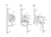
図2は、図1の主流路2の断面を示す図で、(1)は主流路2の捕捉部位3が設けられていない位置a−aの断面図、(2)は主流路2の捕捉部位3が設けられている位置b−bの断面図である。主流路2の幅及び深さ、捕捉部位3の幅及び深さは、分離する対象物の大きさに応じて適宜設定すればよいが、図2(2)の下段部分の流路で除去すべき微粒子を後述するシース液を用いてチップから排出し、上段の捕捉部位で目的の微粒子を捕捉することから、前記捕捉部位で捕捉される微粒子の大きさをX、分離・除去される微粒子の大きさをYとした場合、前記主流路2の幅AはY<A<X、前記捕捉部位3の幅Bは1X<B<10X、前記捕捉部位3の深さCは1X<C<10X、前記捕捉部位3における流路の深さDはY<Dとすることが望ましく、前記捕捉部位3以外の流路の深さEはE=C+Dとすることが好ましい。B及びCを10X以上にすると、捕捉部位3の大きさに対する主流路2の幅が小さくなりすぎ、微粒子の分離・除去の処理能力が低下するので好ましくない。なお、前記の1X<B<10X、1X<C<10Xは、捕捉部位3の下段の主流路2が一本の例であるが、捕捉部位3の下段に複数本の主流路2を設けて微粒子分離の処理能力を上げれば、B及びCは10X以上であってもよい。
2 is a cross-sectional view of the
また、前記の数値は目的の微粒子の濃縮等、捕捉部位で複数個の微粒子を捕捉する場合の範囲であるが、捕捉した微粒子を分析等するために個々の捕捉部位3で捕捉する微粒子を1個とする場合は、1X<B<2X、1X<C<2Xとすればよい。更に、捕捉部位3で捕捉される目的の微粒子が生体細胞等、形状が変化し易い場合は、流体力により細胞が変形して捕捉部位3をすり抜けてしまう可能性がある。そのため、主流路の幅Aは目的の微粒子の形状の変化割合に応じて適宜選択すればよく、例えば、CTCの場合は、前記主流路2の幅AをY<A<0.8Xとすることが好ましい。
In addition, the above numerical value is a range in the case where a plurality of fine particles are captured at the capture site, such as concentration of target fine particles, but 1 particle is captured at each
全血から、CTCを捕捉し、CTC以外の赤血球、白血球等の血球細胞を除去する場合、主流路2の幅Aは、CTCの直径(15〜30μm)よりは小さく、赤血球、白血球等の血球細胞(約7μm)より大きくすればよく、8〜12μmが好ましい。一方、捕捉部位3は、CTCを捕捉できる形状であれば特に制限はなく、円形、略正方形、6、8等の多角形が挙げられ、捕捉部位3でCTCを捕捉する必要があることから、捕捉部位3の幅B及び深さCは、CTCの直径より大きい必要があり、16〜36μmが好ましい。なお、捕捉部位3の幅とは、捕捉部位3の形状が円形の場合は直径、正方形の場合は1辺、6、8等の多角形の場合は多角形の中心を通る最短となる長さを意味する。
When capturing CTC from whole blood and removing blood cells such as red blood cells and white blood cells other than CTC, the width A of the
また、捕捉部位3においては、(2)で示される上段部分でCTCを捕捉し、下段部分の主流路2で、後述するシース液で血球細胞を除去することから、主流路2の深さDは、少なくとも血球細胞の直径より大きい必要があり、また、1以上の血球細胞を同時に除去できることが好ましいことから、深さDは、8〜20μmが好ましい。捕捉部位3が設けられていない主流路2の深さEはC+Dとすればよい。
Further, in the
上記の例は、全血からCTCを分離する場合の大きさであるが、例えば、腹腔洗浄液において血球細胞または中皮細胞(約7〜15μm)から胃がん細胞塊(25〜50μm)を分離する場合は、主流路2の深さDは8〜24μmとすればよく、捕捉部位3の幅B及び深さCは26μm〜60μmとすればよい。
The above example is the size when separating CTC from whole blood, for example, when separating gastric cancer cell mass (25-50 μm) from blood cells or mesothelial cells (about 7-15 μm) in the peritoneal lavage fluid The depth D of the
前記微粒子分離用マイクロ流路チップは、フォトリソグラフィー技術を用いて作製することができる。図3は作製手順の一例を示したフローチャートで、図1及び2に示す微粒子分離用マイクロ流路チップは2段形状になっているため、2段露光技術を用いて作製する。 The microchannel chip for separating fine particles can be manufactured using a photolithography technique. FIG. 3 is a flowchart showing an example of a manufacturing procedure. Since the micro-channel chip for separating fine particles shown in FIGS. 1 and 2 has a two-stage shape, it is manufactured using a two-stage exposure technique.
先ず、シリコン基板を超音波洗浄機により有機洗浄し、ベイクする。次いで、図3に示す以下の手順で作製する。
1.ネガティブフォトレジスト(SU−8)をSiの基板上にスピンコートし、ホットプレート上でプリベイクする。
2.クロムマスク等のフォトマスクを用い露光する。
3.ホットプレート上でポストエクスポージャーベイクを行い、現像液(PMシンナー等)を用い現像した後、超純水を用いリンスし、スピンドライヤー等で水分をとばし乾燥させる。
4.2段目のSU−8のネガティブフォトレジストをスピンコートし、プリベイクする。
5.クロムマスク等を用い露光する。
6.ポストエクスポージャーベイク、現像、リンスを行い、パターンを形成する。
7.形成されたパターンを、ポリジメチルシロキサン(PDMS)に転写する。
8.形成されたパターンからPDMSを分離する。
9.PDMS表面を親水化する。First, the silicon substrate is organically cleaned with an ultrasonic cleaner and baked. Subsequently, it manufactures in the following procedures shown in FIG.
1. A negative photoresist (SU-8) is spin-coated on a Si substrate and prebaked on a hot plate.
2. Exposure is performed using a photomask such as a chrome mask.
3. After performing post-exposure baking on a hot plate and developing with a developer (PM thinner or the like), rinse with ultrapure water, and then dry with a spin dryer or the like.
4. Spin coat the second stage SU-8 negative photoresist and pre-bake.
5. Exposure is performed using a chromium mask or the like.
6). Post-exposure baking, development and rinsing are performed to form a pattern.
7). The formed pattern is transferred to polydimethylsiloxane (PDMS).
8). PDMS is separated from the formed pattern.
9. PDMS surface is hydrophilized.
有機洗浄は、アセトン、エタノール等、半導体製造分野で一般的に用いられている洗浄剤であれば特に制限はされない。また、上記の手順では、基板としてSiを用いた例を示したが、フォトリソグラフィー技術分野で一般的に用いられている材料であれば基板の材料は特に限定はされず、例えば、シリコンカーバイド、サファイア、リン化ガリウム、ヒ化ガリウム、リン化ガリウム、窒化ガリウム等が挙げられる。ネガティブフォトレジストもSU−8に限定されず、例えば、KMPR等、また、ポジティブフォトレジストであれば、例えば、PMER、AZ等一般的に使用されているレジストを用いることもできる。 The organic cleaning is not particularly limited as long as it is a cleaning agent generally used in the semiconductor manufacturing field, such as acetone and ethanol. In the above procedure, an example in which Si is used as a substrate has been shown. However, the material of the substrate is not particularly limited as long as it is a material generally used in the photolithography technical field. For example, silicon carbide, Examples include sapphire, gallium phosphide, gallium arsenide, gallium phosphide, and gallium nitride. The negative photoresist is not limited to SU-8. For example, a commonly used resist such as PMER or AZ can be used as long as it is a positive photoresist.
また、本発明の微粒子分離用マイクロ流路チップの材料としては、上記手順ではPDMSを用いたが、例えば、PMMA(Poly(methyl methacrylate))、PC、硬質ポリエチレン製等のプラスチック、ハイドロゲル、ガラス等を用いてもよい。 Further, as the material for the microchannel chip for separating fine particles of the present invention, PDMS is used in the above procedure. For example, PMMA (Poly (methyl methacrylate)), PC, plastic made of hard polyethylene, hydrogel, glass, etc. Etc. may be used.
チップ表面は親水化処理されることで、マイクロチップに液体を注入した際、溝に気泡が入ることを防止できる。親水化処理方法としては、プラズマ処理、界面活性剤処理、PVP(ポリビニルピロリドン)処理、光触媒等が挙げられ、例えば、チップ表面を10〜30秒間プラズマ処理することで、チップ表面に水酸基を導入することができる。また、チップ表面の浸水化処理は、主流路、後述する分岐流路及び捕捉部位のみを親水化処理してもよい。主流路、分岐流路及び捕捉部位以外の部分は親水化処理されていないので、サンプル液やシース液は主流路、分岐流路及び捕捉部位に流れやすくなり、微粒子の捕捉効率を向上することができる。主流路、分岐流路及び捕捉部位の親水化処理は、他の部分をマスク等で多い、上記と同様の方法で親水化処理すればよい。あるいは、上記マスクをポジネガ反転させてフッ素樹脂等を蒸着させて、疎水処理を行ってもよい。 Since the chip surface is hydrophilized, bubbles can be prevented from entering the grooves when a liquid is injected into the microchip. Examples of the hydrophilization treatment method include plasma treatment, surfactant treatment, PVP (polyvinylpyrrolidone) treatment, photocatalyst, etc. For example, plasma treatment is performed on the chip surface for 10 to 30 seconds to introduce hydroxyl groups on the chip surface. be able to. Further, in the water immersion treatment on the chip surface, only the main flow channel, a branch flow channel to be described later, and the capturing site may be subjected to a hydrophilic treatment. Since parts other than the main channel, the branch channel and the capture site are not hydrophilized, the sample liquid and the sheath liquid can easily flow to the main channel, the branch channel and the capture site, thereby improving the capture efficiency of the fine particles. it can. The hydrophilization treatment of the main channel, the branch channel, and the capturing site may be performed by a method similar to the above, in which other portions are often masked. Alternatively, a hydrophobic treatment may be performed by reversing the mask positive / negative and depositing a fluororesin or the like.
図4は、本発明の微粒子分離用マイクロ流路チップの他の例の概略を示す図である。図4の(1)〜(3)に示す例は、いずれも、主流路11から分岐する分岐流路12を設け、該分岐流路12中に捕捉部位13が設けられ、そして、分岐流路12は、再び主流路11と接続している。なお、分岐流路12に設けられる捕捉部位13は図4の(1)〜(3)に示されるように、主流路11と接触していてもよい。(1)は分岐流路12に設けられた捕捉部位13が円形状の例を示しており、(2)は主流路11の流れ方向の鉛直方向に、角が滑らかな略正方形の捕捉部位13が設けられた例を示しており、(3)は主流路11の流れ方向に角を滑らかにした略正方形の捕捉部位13が設けられるとともに主流路11の流れ方向を約90度変化させた例を示している。
FIG. 4 is a diagram showing an outline of another example of the microchannel chip for separating fine particles of the present invention. In any of the examples shown in (1) to (3) of FIG. 4, a branch channel 12 that branches from the
主流路11及び分岐流路12の幅・深さ、捕捉部位13の大きさは、分離する対象物の大きさに応じて適宜設定すればよいが、図2に示す微粒子分離用マイクロ流路チップと同様、捕捉部位13で捕捉される微粒子の大きさをX、分離・除去される微粒子の大きさをYとした場合、前記主流路11及び分岐流路12の幅FはY<F<Xが好ましく、前記捕捉部位13の幅G、並びに前記主流路11、分岐流路12及び捕捉部位13の深さHは、1X<G<10X、1X<H<10Xとすることが好ましいが、捕捉部位13に連結する分岐流路12の数を複数本設ける場合、G及びHは10X以上であってもよい。また、捕捉部位13で捕捉する微粒子を1個とする場合は、1X<G<2X、1X<H<2Xとすることが好ましい。更に、捕捉部位13で捕捉される目的の微粒子が生体細胞等、形状が変化し易い場合は、Y<F<0.8Xとすることが好ましい。捕捉部位13の下方にも更に流路を設ける場合は、主流路11、分岐流路12及び捕捉部位13の下方に、幅がF、深さJがY<Jの流路を更に設ければよい。
The width and depth of the
例えば、全血から、CTCを捕捉し、CTC以外の赤血球、白血球等の細胞を除去する場合、主流路11の幅は、CTCの直径(15〜30μm)よりは小さく、血球細胞(約7μm)より大きくすればよく、8〜12μmが好ましい。一方、捕捉部位13は、CTCを捕捉する必要があることから、捕捉部位13の大きさは、CTCの直径より大きい必要がある。例えば、図4(1)の捕捉部位13が円形状の場合は、直径14が16〜36μmであることが好ましく、(2)及び(3)の捕捉部位13が略正方形の場合は、辺15、16が、16〜36μmであることが好ましい。なお、捕捉部位13の形状は、CTCが捕捉できる形状であれば特に制限はなく、6,8角形等の多角形でもよく、多角形の場合は上記のとおり、中心を通る最短となる線の長さが16〜36μmとすればよい。
For example, when CTC is captured from whole blood and cells such as red blood cells and white blood cells other than CTC are removed, the width of the
図4(1)〜(3)に示される形状の微粒子分離用マイクロ流路チップの場合、CTCは捕捉部位13にトラップされるが、後述するシース液は主流路11を流れるため、CTCはシース液の流体力を受けることがない。さらに、CTC以外の血球細胞の多くは、後述するシース液と共に主流路11を流れ、捕捉部位13に流入してしまった血球細胞は、捕捉部位13から更に伸びている分岐流路12を通り再び主流路11に戻すことができる。したがって、図1及び2に示される微粒子分離用マイクロ流路チップと違い、図4に示される微粒子分離用マイクロ流路チップでは、CTCとCTC以外の細胞の主要な流れが異なることから、捕捉部位13の下方に流路を形成することは必須ではない。下方に流路を設けない場合、主流路11、分岐流路12及び捕捉部位13の深さは16〜36μmが好ましい。捕捉部位13の下方に流路を設ける場合は、図2に示されている場合と同様、捕捉部位13の下方の流路の深さは8〜20μmが好ましく、捕捉部位13以外の部分については、捕捉部位13と流路の深さを合計した深さとすればよい。
In the case of the microchannel chip for separating fine particles having the shape shown in FIGS. 4 (1) to 4 (3), CTC is trapped in the
図4に示される形状の微粒子分離用マイクロ流路チップは、段差を設けない場合、図4に示される形状のマスクを用い、上記手順「4.〜6.」の2段目のレジスト層を設ける手順を省略する以外は、上記と同様の手順で作製することができる。また、段差を設ける場合は、図4に示される形状のマスクを用いる以外は、上記と同様の手順で作製することができる。 If the microchannel chip for separating fine particles shown in FIG. 4 is not provided with a step, use the mask of the shape shown in FIG. It can be produced by the same procedure as described above except that the providing procedure is omitted. In the case where a step is provided, it can be manufactured in the same procedure as described above except that a mask having the shape shown in FIG. 4 is used.
次に、上記の微粒子分離用マイクロ流路チップを用いた微粒子分離用システム及び使用方法について説明する。 Next, a system for separating fine particles using the micro-channel chip for separating fine particles and a method for using the same will be described.
図5は、本発明の微粒子分離用システムの概略及び使用形態を示す図で、微粒子分離用マイクロ流路チップとサンプル液用薄板及びシース液用薄板を相対移動させることでメニスカスを発生させる実施形態を示している。本実施形態の微粒子分離用システムは、微粒子分離用マイクロ流路チップ、サンプル液用薄板21、シース液用薄板22、シース液を吸引する図示しない吸引装置を含んでいる。 FIG. 5 is a diagram showing an outline and a usage pattern of the microparticle separation system of the present invention. An embodiment in which a meniscus is generated by relatively moving a microfluidic chip for microparticle separation, a thin plate for sample liquid, and a thin plate for sheath liquid. Is shown. The particle separation system of the present embodiment includes a microchannel chip for particle separation, a thin plate 21 for sample liquid, a thin plate 22 for sheath liquid, and a suction device (not shown) that sucks the sheath liquid.
サンプル液用薄板21、シース液用薄板22は、ガラス、プラスチック等、サンプルやシース液と反応しないものであれば特に制限はない。シース液としては、分離すべき微粒子に損傷等を与えないものであれば特に制限はなく、全血をサンプルとして用いる場合は、リン酸緩衝生理食塩水(PBS)、トリス緩衝液等各種緩衝液、疑似体液(SBF)、一般的な細胞培養液等、一般的に使用されているシース液であれば特に制限はない。 The sample liquid thin plate 21 and the sheath liquid thin plate 22 are not particularly limited as long as they do not react with the sample or the sheath liquid, such as glass and plastic. The sheath solution is not particularly limited as long as it does not damage the microparticles to be separated. When using whole blood as a sample, various buffer solutions such as phosphate buffered saline (PBS), Tris buffer, etc. The sheath liquid is not particularly limited as long as it is a commonly used sheath liquid such as pseudo body fluid (SBF) and general cell culture fluid.
図5は、サンプルとして全血を用いた例が示されており、全血23を微粒子分離用マイクロ流路チップ1とサンプル液用薄板21の間に注入し、微粒子分離用マイクロ流路チップとサンプル用薄板21を相対的に移動させることで、メニスカス25が発生する。
FIG. 5 shows an example in which whole blood is used as a sample.
図6は、メニスカスの発生原理を説明する図で、本発明では、移流集積法と呼ばれる、気液界面に存在する微粒子間の毛管力(とくに横毛管力:lateral capillary forceと呼ばれる)を利用して、微粒子同士を細密充填構造に配列する手法を用いている。微粒子が溶液に分散した懸濁液のメニスカスを基板上に形成すると、メニスカスの先端において、図に示すように微粒子が溶液から頭を出す箇所が形成される。この頭が出ている箇所では、界面張力及び重力により下に押し付けられる力が微粒子に発生しながらメニスカスと共に移動し、微粒子はチップに設けられたマイクロ流路に捕捉される。また、シース液も同様にメニスカスを発生させることで、シース液が微細な主流路内に入り易くなる。 FIG. 6 is a diagram for explaining the principle of meniscus generation. In the present invention, the capillary force between fine particles existing at the gas-liquid interface (particularly referred to as lateral capillary force) is called an advection accumulation method. Thus, a method is used in which fine particles are arranged in a closely packed structure. When a meniscus of a suspension in which fine particles are dispersed in a solution is formed on a substrate, a portion where the fine particles protrude from the solution is formed at the tip of the meniscus as shown in the figure. At the place where the head is protruding, the force pressed downward by the interfacial tension and gravity is generated along with the meniscus while being generated in the fine particles, and the fine particles are captured by the microchannel provided in the chip. Similarly, the sheath liquid also generates a meniscus so that the sheath liquid can easily enter the fine main flow path.
ここで、図1のb−b断面図である図2(2)に示すように、マイクロ流路は2段形状になっており、CTCは上段の捕捉部位3にトラップされ、サイズの小さな血球細胞は下段の流路に落ちる。さらに、流路の上流側に、微粒子分離用マイクロ流路チップ1とシース液用薄板22の間にシース液24を注入しておき、そして、微粒子分離用マイクロ流路チップ1とシース液用薄板22を相対移動させながら図示しない吸引装置で下流側から吸引することによりシース液を上流から下流に流し、CTCを捕捉部位3にトラップしたまま血球細胞を洗い流すことで、CTCを効率的に分離することができる。また、図4に示す形状の微粒子分離用マイクロ流路チップを用いた場合は、CTCは捕捉部位13にトラップされるが、他の血球細胞等はシース液と共に、主流路11及び/又は分岐流路12を通って洗い流すことができる。なお、メニスカスを発生させるためには、微粒子分離用マイクロ流路チップを固定してサンプル液用薄板21及びシース液用薄板22を移動させてもよいし、サンプル液用薄板21及びシース液用薄板22を固定し微粒子分離用マイクロ流路チップを移動させてもよい。
Here, as shown in FIG. 2 (2) which is a cross-sectional view taken along the line bb of FIG. 1, the microchannel has a two-stage shape, and the CTC is trapped in the
微粒子分離用マイクロ流路チップと、サンプル液用薄板21及びシース液用薄板22との間隔は、700〜1000μmとすることが好ましい。700μmより小さいとサンプル液の導入量が減少し処理能力が低下し、1000μmより大きいとメニスカス力が低下し十分な分離が得られない。なお、上記間隔は、マイクロステージで調整することができる。また、微粒子分離用マイクロ流路チップと、サンプル液用薄板21及びシース液用薄板22との相対移動速度は、20〜50μm/sが好ましい。20μm/sより遅いと、処理時間が長くなり処理能力が低下し、50μm/sより速いと微粒子が捕捉されずに分離効率が低減する。 The distance between the microchannel chip for separating fine particles, the thin plate 21 for sample liquid, and the thin plate 22 for sheath liquid is preferably 700 to 1000 μm. If it is smaller than 700 μm, the amount of introduced sample solution is reduced and the processing capacity is lowered. If it is larger than 1000 μm, the meniscus force is lowered and sufficient separation cannot be obtained. In addition, the said space | interval can be adjusted with a microstage. The relative moving speed of the microfluidic chip for separating fine particles, the thin plate for sample liquid 21 and the thin plate for sheath liquid 22 is preferably 20 to 50 μm / s. When it is slower than 20 μm / s, the processing time becomes longer and the processing capacity is lowered, and when it is faster than 50 μm / s, fine particles are not captured and the separation efficiency is reduced.
シース液の流速は、20〜500μm/sが好ましい。20μm/sより遅いと血球細胞を洗浄する能力の低下により分離効率が低減し、500μm/sより速いと一旦捕捉されたCTCが吸引され分離効率が低減する。シース液の流速は、吸引装置の吸引力により調整すればよい。吸引装置は吸引ポンプ、マイクロシリンジ等、液体を吸引できるものであれば特に制限はない。なお、図5に示す例は、微粒子分離用マイクロ流路チップとシース液用薄板22との間にシース液24を必要に応じて注入する形式であるが、シース液用薄板22の一端に、シース液容器又はシース液容器から伸長しているチューブ等を連結することで、シース液を自動的に供給できるようにしてもよい。
The flow rate of the sheath liquid is preferably 20 to 500 μm / s. If it is slower than 20 μm / s, the separation efficiency is reduced due to a decrease in the ability to wash blood cells, and if it is faster than 500 μm / s, once captured CTC is sucked and the separation efficiency is reduced. The flow rate of the sheath liquid may be adjusted by the suction force of the suction device. The suction device is not particularly limited as long as it can suck liquid, such as a suction pump and a microsyringe. The example shown in FIG. 5 is a form in which the
図7は、本発明の微粒子分離用システムの概略及び使用形態を示す図で、微粒子分離用マイクロ流路チップとカバー板を相対移動させずサンプル液を吸引することでメニスカスを発生させる実施形態を示している。本実施形態の微粒子分離用システムは、微粒子分離用マイクロ流路チップ1、該微粒子分離用マイクロ流路チップ1に重ねサンプル液及びシース液を吸引することでメニスカスを発生させるためのカバー板31、図示しない吸引手段及び/又は吸引装置を少なくとも含んでいる。図7に示す実施形態では、微粒子分離用マイクロ流路チップ1に排出口5を設ける必要は無く、複数の主流路2の一端に連結する排出路4から、サンプル液及びシース液を吸引できるようにすればよい。サンプル液及びシース液は、後述する吸引手段及び/又は吸引装置を用いて、排出路4から直接吸引・排出してもよいし、長手方向に形成した横溝33と該横溝33に連通する吸引孔34を含む吸引ユニット35を介して吸引手段及び/又は吸引装置により吸引してもよい。本実施形態では、後述する吸引手段及び/又は吸引装置を微粒子分離用マイクロ流路チップに密着して、主流路2から直接サンプル液及びシース液を吸引することもでき、その場合は、排出路4を設けなくてもよい。なお、本実施形態の吸引手段及び/又は吸引装置を用いて、必要に応じて吸引ユニット35を介してサンプル液及びシース液32を排出路4又は主流路2から直接吸引・排出する形態は、図5に示す実施形態にも適用することができる。また、本実施形態では、吸引手段及び/又は吸引装置を用いてサンプル液を吸引することでサンプル液中に含まれる微粒子を分離することから、希釈したサンプル液を使用すればサンプル液自体がシース液の役割をするので、サンプル液を流した後にシース液を流すことは必須ではない。目的微粒子の高純度な分離の場合はシース液を流すことで残存している除去する微粒子を洗い流す等、分離の目的に応じてシース液を流すか否かの選択を行えばよい。
FIG. 7 is a diagram showing an outline and a usage pattern of the particulate separation system of the present invention. An embodiment in which a meniscus is generated by sucking a sample solution without moving the particulate separation microchannel chip and the cover plate relative to each other. Show. The microparticle separation system of the present embodiment includes a
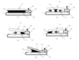
図8は、図7のA−A′断面図で、本実施形態におけるメニスカスの発生原理を説明する図である。図8(1)に示すように、微粒子分離用マイクロ流路チップ1とカバー板31の間にサンプル液、シース液32を注入し、図示しない吸引手段及び/又は吸引装置で吸引すると、サンプル液、シース液32は主流路2から排出路4を経由して排出される。その際、微粒子分離用マイクロ流路チップ1及びカバー板31との間のサンプル液、シース液32には、毛細管力が発生するため、図8(2)に示すようなメニスカスが発生する。
FIG. 8 is a cross-sectional view taken along the line AA ′ of FIG. 7 and illustrates the principle of meniscus generation in the present embodiment. As shown in FIG. 8 (1), when the sample liquid and the sheath liquid 32 are injected between the
なお、図8(2)に示すサンプル液及びシース液32の移動方向は、微粒子分離用マイクロ流路チップ1に対してカバー板31を平行に配置した場合であり、例えば、図8(3)に示すように、排出路4側のカバー板31を微粒子分離用マイクロ流路チップ1に近付けるように傾斜して配置すると、サンプル液及びシース液32に係る圧力のため、サンプル液及びシース液32は排出路4側に移動する。逆に、図8(4)に示すように、微粒子分離用マイクロ流路チップ1の排出路4側とは反対側のカバー板31を微粒子分離用マイクロ流路チップ1に近付けるように傾斜して配置すると、サンプル液及びシース液32に係る圧力のため、サンプル液及びシース液32は排出路4とは反対側に移動する。図8(2)〜(4)の何れの実施形態でも本発明の実施をすることができるが、図8(3)に示す実施形態は、サンプル液及びシース液32が排出路4側に近付くことから、吸引手段及び/又は吸引装置の吸引力を小さくすることができるので好ましい。微粒子分離用マイクロ流路チップ1とカバー板31の間隔は、上記のサンプル液用薄板21と同様に、700〜1000μmの間が好ましく、この間隔の範囲内で、マイクロステージを用いて調整すればよい。カバー板31を傾斜する場合は、6°〜18°程度傾けることが好ましい。傾斜角度が6°より小さい場合は、サンプル液及びシース液に係る圧力が不足し、18°より大きい場合は、微粒子の捕捉に有効なメニスカスの角度より大きくなり過ぎるので好ましくない。図8(5)に示す実施形態は、吸引側にサンプル液及びシース液32のメニスカスを発生させないように、第2のカバー板311を設けたもので、閉じられた流路系を構成できることから安定した吸引を行うことができる。
The moving direction of the sample liquid and the sheath liquid 32 shown in FIG. 8 (2) is the case where the
カバー板31及び第2のカバー板311は、上記のサンプル液用薄板21と同様の材料で作製すればよい。また、カバー板31の大きさは特に制限は無いが、本実施形態では、カバー板31を移動することなくメニスカスを発生することができることから、処理効率を向上させるためには、微粒子分離用マイクロ流路チップ1に形成した主流路2の全てを覆うことができる大きさで形成することが望ましい。また、第2のカバー板311の大きさは、主流路2と直交する横方向の長さはカバー板31と同じ長さにすればよく、幅はメニスカスが発生しない範囲内で適宜調整すればよい。
The
サンプル液及びシース液32の吸引手段としては、例えば、布、コットン、スポンジ、セーム皮等の吸引パッドが挙げられ、排出路4又は主流路2に直接吸引パッドを当接してサンプル液及びシース液を吸引・排出すればよい。 Examples of the suction means for the sample liquid and the sheath liquid 32 include a suction pad such as cloth, cotton, sponge, and chamois. Can be sucked and discharged.
サンプル液及びシース液32の吸引・排出は、吸引ユニット35を介して行ってもよい。図9(1)は吸引ユニット35の概略を示す上面図で、図9(2)は吸引ユニット35のB−B′断面図を示している。吸引ユニット35は、サンプル液及びシース液32を毛管力で吸引することができる横溝33と該横溝33に連通し図示しない吸引装置と接続するための吸引孔34が設けられている。横溝33の幅は、少なくとも除去された微粒子を通過させる必要があることから、サンプルが全血の場合は少なくとも8μm以上、処理能力を上げるためには10μm以上とすることがより好ましい。一方、横溝33の幅は毛管力が発生すれば特に上限は無く、吸引するサンプル液、シース液の量や毛管力等を考慮して適宜調整すればよく、例えば、200μm程度の幅を設けてもよい。吸引ユニット35を排出路4又は主流路2上に当接させ、毛管力でサンプル液及びシース液32を横溝33に吸引することで、サンプル液及びシース液32を排出路4又は主流路2から排出することができる。また、横溝33に吸引したサンプル液及びシース液32を、ポンプ、マイクロシリンジ等の吸引装置を用い、吸引孔34を通して吸引・排出してもよい。排出するサンプル液、シース液の量が多く、横溝33のみでは吸引できない場合は、吸引装置を組合せて用いればよい。吸引孔34の数は特に制限は無く、各主流路2を流れるサンプル液及びシース液32の流速に大きな差異が発生しない程度の数を設ければよい。
The sample liquid and the sheath liquid 32 may be sucked / discharged via the
また、横溝33の幅を大きくし、横溝33に上記の布、コットン、スポンジ、セーム皮等の吸引手段を挿入し、該吸引手段に吸収したサンプル液及びシース液32を、吸引孔34をとおして吸引装置で吸引してもよい。本実施形態においては、主流路2を流れるサンプル液及びシース液の流速は、吸引手段及び/又は吸引装置の吸引力により調整する。そのため、単に吸引手段でサンプル液及びシース液32を吸引する、又は、毛管力により横溝33にサンプル液及びシース液32を吸引するより、吸引手段に吸引したサンプル液及びシース液を更に吸引装置で吸引することで、サンプル液及びシース液の吸引速度を安定に保つことができる。吸引装置と吸引孔34は、シリコン等のチューブを用いて連結すればよい。
Further, the width of the
吸引ユニット35を構成する材料は、アクリル、ナイロン、テフロン(登録商標)等の樹脂、又はガラス等、サンプル液やシース液と反応しないものであれば特に制限はない。吸引ユニット35は、ドリル及びエンドミル等の切削工具を用いた切削加工、又は吸引ユニット35の形状のモールドを作製し射出成形により作製することができる。
The material constituting the
本実施形態の微粒子分離用システムは、先ず、微粒子分離用マイクロ流路チップ1とカバー板31の間にサンプル液を入れ、吸引手段及び/又は吸引装置によりサンプル液を吸引し、次に、必要に応じて、シース液を微粒子分離用マイクロ流路チップ1とカバー板31の間に入れ、シース液を吸引することで、例えば、血液サンプル中のCTCを捕捉部位にトラップし、他の血球細胞等はシース液と共に洗い流すことができる。微粒子分離用マイクロ流路チップ1とカバー板31の間へのサンプル液又はシース液は、シリンジ等を用いて微粒子分離用マイクロ流路チップ1とカバー板31の間から注入してもよいし、カバー板31に孔を設け、該孔からサンプル液及びシース液を注入してもよい。
In the particulate separation system of this embodiment, first, a sample liquid is put between the
サンプル液及びシース液32の流速は、20〜500μm/sが好ましい。20μm/sより遅いと血球細胞を分離・洗浄する能力の低下により分離効率が低減し、500μm/sより速いと一旦捕捉されたCTCが吸引され分離効率が低減する。サンプル液及びシース液の流速は、吸引手段及び/又は吸引装置の吸引力により調整すればよい。 The flow rate of the sample liquid and the sheath liquid 32 is preferably 20 to 500 μm / s. If it is slower than 20 μm / s, the separation efficiency is reduced due to a decrease in the ability to separate and wash blood cells, and if it is faster than 500 μm / s, once captured CTC is sucked and the separation efficiency is reduced. The flow rates of the sample liquid and the sheath liquid may be adjusted by the suction force of the suction means and / or the suction device.
なお、本実施形態では、サンプル液を先ず流した後に、必要に応じてシース液を流す。したがって、全血等の粘性の高いサンプル液をそのまま吸引すると、大きな吸引力が必要となる。そのため、サンプル液として血液を用いる場合は、シース液等を用いて、2〜10倍、好ましくは3〜5倍程度に希釈してもよい。本実施形態では、相対移動により複数の主流路2に順番にメニスカスを発生させるのではなく、微粒子分離用マイクロ流路チップ1とカバー板31が重なっている部分の主流路2に対して同時にメニスカスを発生することができるので、全血を希釈した場合でも、分離に要する時間を十分短くすることができる。
In this embodiment, the sample liquid is first flowed, and then the sheath liquid is flowed as necessary. Therefore, if a highly viscous sample liquid such as whole blood is sucked as it is, a large suction force is required. Therefore, when blood is used as the sample solution, it may be diluted 2 to 10 times, preferably about 3 to 5 times, using a sheath solution or the like. In the present embodiment, the meniscus is not generated in order in the plurality of
本発明の微粒子分離用システムは、捕捉部位での微粒子の捕捉効率を上げるための磁場発生装置及び/又は電場発生装置等を設けてもよい。例えば、捕捉部位下面に磁場発生装置として永久磁石または電磁石を設置して磁場ポテンシャル場を発生させ、EpCAM抗体等を標識した磁性粒子を特異的に吸着させたCTC、又は磁性粒子を非特異的に吸着させたCTC(エンドサイトーシスから取り込む)等、捕捉したい粒子に磁性を帯びさせた上で、本発明の微粒子分離用システムを用いると、磁性標識されていない他の粒子から精度よく分離することが可能である。 The fine particle separation system of the present invention may be provided with a magnetic field generation device and / or an electric field generation device for increasing the capture efficiency of fine particles at the capture site. For example, a permanent magnet or an electromagnet is installed as a magnetic field generating device on the lower surface of the capture site to generate a magnetic field potential field, and CTC that specifically adsorbs magnetic particles labeled with EpCAM antibody or the like, or nonspecifically magnetic particles. The particles to be captured, such as adsorbed CTC (taken from endocytosis), are magnetized, and when the fine particle separation system of the present invention is used, the particles are separated from other particles that are not magnetically labeled. Is possible.
また、捕捉部位下面又は捕捉部位側面に、電場発生装置として電極を設けて電場ポテンシャル場(不均一電場中)を発生させ、CTCと周囲媒質の分極と電場の勾配により生じる静電気力(クーロン力)を用いてCTCの捕捉をアシストすることも可能である。 Electrostatic force (Coulomb force) generated by polarization of the CTC and the surrounding medium and the gradient of the electric field by generating an electric field potential field (in a non-uniform electric field) by providing an electrode as an electric field generator on the lower surface of the capturing site or the side surface of the capturing site. It is also possible to assist CTC capture using.
捕捉されたCTCの検出方法としては、FITCやPEで標識された抗EpCAM抗体等のCTC特異的な抗体を用いて蛍光染色して蛍光顕微鏡等により観察することにより行うことができる。また、光学顕微鏡を用いて明視野観察を行う場合には、パパニコロウ染色やギムザ染色を行うことで細胞内の核、細胞質等の形態的特徴を指標としてCTC検出を行うことが出来る。特に、捕捉したCTCを長期的に観察する際には、光学顕微鏡を用いて明視野観察することが好ましい。 The captured CTC can be detected by fluorescent staining with a CTC-specific antibody such as an anti-EpCAM antibody labeled with FITC or PE and observing with a fluorescence microscope or the like. In addition, when performing bright field observation using an optical microscope, CTC detection can be performed using morphological features such as intracellular nuclei and cytoplasm as an index by performing Papanicolaou staining or Giemsa staining. In particular, when observing the captured CTC for a long period of time, it is preferable to perform bright field observation using an optical microscope.
以下に実施例を掲げ、本発明を具体的に説明するが、この実施例は単に本発明の説明のため、その具体的な態様の参考のために提供されているものである。これらの例示は本発明の特定の具体的な態様を説明するためのものであるが、本願で開示する発明の範囲を限定したり、あるいは制限することを表すものではない。 The present invention will be described in detail with reference to the following examples, which are provided merely for the purpose of illustrating the present invention and for reference to specific embodiments thereof. These exemplifications are for explaining specific specific embodiments of the present invention, but are not intended to limit or limit the scope of the invention disclosed in the present application.
<実施例1>
〔微粒子分離用マイクロ流路チップの作製〕
先ず、シリコン基板をアセトン・エタノール・超純水の順に、45kHzで5分間ずつ超音波洗浄機により有機洗浄し、145℃で20分間ベイクした。次に、シリコン基板上にSU−8をスピンコートし、ホットプレート上で95℃で30分間、プリベイクした。次に、捕捉部位3の形状が略8角形のクロムマスクを用い露光後、ホットプレート上で95℃で2分間、ポストエクスポージャーベイクを行い、PMシンナーを用い現像した。現像後は、超純水を用いリンスし、スピンドライヤー等で水分をとばし乾燥させ、1段目の処理を行った。次いで、SU−8をスピンコートし、ホットプレート上で95℃で30分間プリベイクした。主流路の形状のクロムマスクを用い露光後、ホットプレート上で95℃で2分間、ポストエクスポージャーベイクを行い、PMシンナーを用い現像した。現像後は、超純水を用いリンスし、スピンドライヤー等で水分をとばし乾燥させ、2段目の処理を行った。形成されたパターンを、ポリジメチルシロキサン(PDMS)に転写し、転写後、両者を分離し、PDMS表面をプラズマ処理(周波数50kHz,出力700W、30秒間)により親水化した。<Example 1>
[Preparation of microchannel chip for fine particle separation]
First, the silicon substrate was subjected to organic cleaning with an ultrasonic cleaner at 45 kHz for 5 minutes in order of acetone, ethanol, and ultrapure water, and baked at 145 ° C. for 20 minutes. Next, SU-8 was spin-coated on a silicon substrate, and prebaked at 95 ° C. for 30 minutes on a hot plate. Next, after exposure using a chromium mask having a substantially octagonal shape of the
図10は実施例1で得られた微粒子分離用マイクロ流路チップの外観を示す写真で、微粒子分離用マイクロ流路チップの大きさは縦30mm、横30mmであった。マイクロ流路は、個々の捕捉部位の中心が流路の中心に一致した略8角形の形状で、捕捉部位の中心を通る最短となる線の長さは約30μm、深さは約30μmであった。また、流路の幅は約10μm、捕捉部位における流路の深さは約20μm、捕捉部位以外の流路の深さは約50μmであった。また、流路と流路の中心間距離は約60μmであった。 FIG. 10 is a photograph showing the appearance of the microchannel chip for particle separation obtained in Example 1, and the size of the microchannel chip for particle separation was 30 mm in length and 30 mm in width. The microchannel has an approximately octagonal shape with the center of each capture site coinciding with the center of the channel, and the shortest line passing through the center of the capture site has a length of about 30 μm and a depth of about 30 μm. It was. Further, the width of the channel was about 10 μm, the depth of the channel at the capturing site was about 20 μm, and the depth of the channel other than the capturing site was about 50 μm. Further, the distance between the centers of the flow paths was about 60 μm.
<実施例2>
実施例1のクロムマスクに代え、図4(1)に示される、主流路及び主流路から分岐し再び主流路に接続する分岐流路を配置し、該分岐流路に円形状の捕捉部位を設けたクロムマスクを用い、2段目の処理を行わなかった以外は、実施例1と同様の手順で微粒子分離用マイクロ流路チップを作製した。<Example 2>
In place of the chrome mask of the first embodiment, a main flow channel and a branch flow channel branched from the main flow channel and connected to the main flow channel as shown in FIG. Using the provided chromium mask, a microchannel chip for separating fine particles was produced in the same procedure as in Example 1 except that the second stage treatment was not performed.
図11は実施例2で得られた微粒子分離用マイクロ流路チップの外観を示す写真で、微粒子分離用マイクロ流路チップの大きさは縦30mm、横30mmであった。捕捉部位は直径約30μmの円形状で、1段形成のため、主流路及び分岐流路の何れの箇所でも深さは約30μmであった。また、主流路及び分岐流路の幅は約8μm、主流路と主流路の中心間距離は約80μmであった。 FIG. 11 is a photograph showing the appearance of the microchannel chip for particle separation obtained in Example 2. The size of the microchannel chip for particle separation was 30 mm in length and 30 mm in width. The capture site was circular with a diameter of about 30 μm, and because of the formation of one stage, the depth was about 30 μm in both the main channel and the branch channel. The width of the main channel and the branch channel was about 8 μm, and the distance between the centers of the main channel and the main channel was about 80 μm.
<実施例3>
実施例2のクロムマスクに変え、図4(2)に示される形状のマスクに変えた以外は、実施例2と同様の手順で微粒子分離用マイクロ流路チップを作製した。得られた微粒子分離用マイクロ流路チップの捕捉部位は、一辺が約30μmの角が滑らかな略正方形で、その他の寸法は、実施例2と同様であった。<Example 3>
A microchannel chip for separating fine particles was produced in the same procedure as in Example 2, except that the chrome mask in Example 2 was replaced with the mask having the shape shown in FIG. The trapping site of the obtained microfluidic chip for separating fine particles was a substantially square with a side of about 30 μm and a smooth corner, and other dimensions were the same as in Example 2.
<実施例4>
実施例2のクロムマスクに変え、図4(3)に示される形状のマスクに変えた以外は、実施例2と同様の手順で微粒子分離用マイクロ流路チップを作製した。<Example 4>
A microchannel chip for separating fine particles was produced in the same procedure as in Example 2, except that the chrome mask in Example 2 was replaced with the mask having the shape shown in FIG.
図12は実施例4で得られた微粒子分離用マイクロ流路チップの外観を示す写真である。写真から明らかなように、実施例2と違い、実施例4(実施例3も同様)では、捕捉部位の上流側と下流側で主流路の位置が変わる。したがって、実施例4では、次の捕捉部位を設ける際に、主流路の位置を一つ上流側の捕捉部位の主流路の位置と一致するようにマスクを設計したが、図4(3)に示す形状と同様の形状のものを繋げ、主流路が階段状になるように配置してもよい。捕捉部位は一辺が約30μmの角が滑らかな略正方形で、その他の寸法は、実施例2と同様であった。 FIG. 12 is a photograph showing the appearance of the microchannel chip for separating fine particles obtained in Example 4. As is apparent from the photograph, unlike the second embodiment, in the fourth embodiment (the same applies to the third embodiment), the position of the main flow path is changed between the upstream side and the downstream side of the capturing site. Therefore, in Example 4, the mask was designed so that the position of the main flow path coincides with the position of the main flow path of the upstream capture site when the next capture site is provided. You may connect the thing of the shape similar to the shape to show, and it may arrange | position so that a main flow path may become step shape. The trapping site was approximately square with a smooth corner with a side of about 30 μm, and the other dimensions were the same as in Example 2.
〔血液サンプルの作製〕
採取したヒト血液20μlに、1.0×10⁴個の胃がん細胞株(ヒト胃がん由来の細胞株(GCIY−GFP)をトリプシン処理でバラバラにしたもの)を懸濁し、がん患者の血液を模した血液サンプルを作製した。なお、がん細胞の平均粒径は25μmであった。[Preparation of blood sample]
In 20 μl of collected human blood, 1.0 × 10 4 gastric cancer cell lines (human gastric cancer-derived cell line (GCIY-GFP) separated by trypsin treatment) are suspended to simulate the blood of cancer patients. A blood sample was prepared. The average particle size of the cancer cells was 25 μm.
<実施例5>
〔微粒子分離用システムの作製及び血液サンプルからのCTC分離実験〕
実施例1〜4で作製された微粒子分離用マイクロ流路チップと、ガラスで作製された縦20mm、横20mmのサンプル液用薄板の間に上記血液サンプル20μlを注入した。微粒子分離用マイクロ流路チップとサンプル液用薄板との間は、マイクロステージを用いて700μmとなるように調整した。また、微粒子分離用マイクロ流路チップと、ガラスで作製された縦10mm、横20mmのシース液用薄板との間にシース液(リン酸緩衝生理食塩水(PBS))10μlを注入した。なお、シース液については、適宜補充した。微粒子分離用マイクロ流路チップは、20μm/sの一定速度で移動させた。シース液の流速は20μm/sとした。<Example 5>
[Production of fine particle separation system and CTC separation experiment from blood sample]
20 μl of the blood sample was injected between the microfluidic chip for separating fine particles produced in Examples 1 to 4 and a thin plate for sample liquid having a length of 20 mm and a width of 20 mm made of glass. The space between the microfluidic chip for separating fine particles and the thin plate for sample solution was adjusted to 700 μm using a microstage. In addition, 10 μl of a sheath solution (phosphate buffered saline (PBS)) was injected between the microchannel chip for separating fine particles and a thin plate for sheath solution made of glass with a length of 10 mm and a width of 20 mm. The sheath liquid was appropriately supplemented. The microchannel chip for fine particle separation was moved at a constant speed of 20 μm / s. The flow rate of the sheath liquid was 20 μm / s.
上記〔血液サンプルからのCTC分離実験〕の結果を図13に示す。従来の抗EpCAM抗体を用いたCTCの捕捉の場合、血中のCTCの100乃至1000分の1程度しか捕捉することができないといわれており、本発明の微粒子分離用マイクロ流路チップは、非常に効率よくCTCを捕捉できることが明らかとなった。 The result of the above [CTC separation experiment from blood sample] is shown in FIG. In the case of capturing CTC using a conventional anti-EpCAM antibody, it is said that only about 1/1000 to 1000 times of CTC in blood can be captured. It was revealed that CTC can be captured efficiently.
また、主流路上に捕捉部位を設けた実施例1と比較し、主流路に分岐流路を設け且つ分岐流路に捕捉部位を設けた実施例2〜4では、CTCの捕捉効率が格段に向上した。これは、実施例1の主流路上に捕捉部位を設けた場合、捕捉されたCTCがシース液の流体力により変形し、捕捉部位から流出したためと考えられる。 In addition, compared with Example 1 in which the capture site is provided on the main channel, in Examples 2 to 4 in which the branch channel is provided in the main channel and the capture site is provided in the branch channel, the CTC capture efficiency is significantly improved. did. This is considered to be because when the capture site was provided on the main channel of Example 1, the captured CTC was deformed by the fluid force of the sheath liquid and flowed out of the capture site.
一方、実施例2〜4の場合、CTCは捕捉部位で捕捉されるが、シース液は主流路を流れるため、CTCが受けるシース液の流体力は大幅に小さくなり、また、捕捉部位に流入した血球細胞は、分岐流路を通って再び主流路に戻すことができるため、CTCの捕捉効率が上がったと考えられる。 On the other hand, in Examples 2 to 4, CTC is captured at the capture site, but since the sheath liquid flows through the main flow path, the fluid force of the sheath liquid received by the CTC is significantly reduced and flows into the capture site. The blood cell can be returned to the main flow path again through the branch flow path, and it is considered that the capture efficiency of CTC has increased.
<実施例6>
捕捉部位の中心を通る最短となる線の長さを約20μm、深さを約20μm、捕捉部位における流路の深さを約30μmとした以外は、実施例1と同様の手順で、微粒子分離用マイクロ流路チップを作製した。<Example 6>
Fine particle separation is performed in the same manner as in Example 1 except that the length of the shortest line passing through the center of the capture site is about 20 μm, the depth is about 20 μm, and the depth of the flow path at the capture site is about 30 μm. A microchannel chip for use was prepared.
<実施例7>
捕捉部位の直径を約20μm、深さを約20μmとした以外は、実施例2と同様の手順で、微粒子分離用マイクロ流路チップを作製した。<Example 7>
A microchannel chip for separating fine particles was produced in the same procedure as in Example 2 except that the diameter of the capture site was about 20 μm and the depth was about 20 μm.
<実施例8>
捕捉部位の一辺の長さを約20μm、深さを約20μmとした以外は、実施例3と同様の手順で、微粒子分離用マイクロ流路チップを作製した。<Example 8>
A microchannel chip for microparticle separation was produced in the same procedure as in Example 3 except that the length of one side of the capture site was about 20 μm and the depth was about 20 μm.
<実施例9>
捕捉部位の一辺の長さを約20μm、深さを約20μmとした以外は、実施例4と同様の手順で、微粒子分離用マイクロ流路チップを作製した。<Example 9>
A microchannel chip for separating fine particles was produced in the same procedure as in Example 4 except that the length of one side of the capture site was about 20 μm and the depth was about 20 μm.
〔ポリスチレンビーズ懸濁液の作製〕
純水20μlに、18μmのポリスチレンビーズ及び7μmのポリスチレンビーズを懸濁したサンプル液を作製した。[Preparation of polystyrene bead suspension]
A sample solution was prepared by suspending 18 μm polystyrene beads and 7 μm polystyrene beads in 20 μl of pure water.
<実施例10>
〔ポリスチレンビーズ懸濁液からの18μmポリスチレンビーズの分離実験〕
実施例6〜9で作製した微粒子分離用マイクロ流路チップ、及びシース液として純水を使用した以外は、上記〔血液サンプルからのCTC分離実験〕と同様の手順で分離実験を行った。形状が変化し難いビーズを分離した場合、実施例6〜9の何れの形状のチップでも、大多数の18μmポリスチレンビーズのトラップが確認された。<Example 10>
[Separation experiment of 18 μm polystyrene beads from polystyrene bead suspension]
Separation experiments were performed in the same procedure as the above [CTC separation experiment from blood sample] except that the microchannel chip for separating fine particles produced in Examples 6 to 9 and pure water was used as the sheath liquid. When beads whose shape hardly changed were separated, traps of the majority of 18 μm polystyrene beads were confirmed in any of the chips of Examples 6 to 9.
<実施例11>
〔微粒子分離用システムの作製〕
吸引ユニットのモールドを作製し、PDMSに該モールドの形状を転写して吸引ユニットを作製した。吸引ユニットの幅は6mm、長さは30mm、横溝の幅は160μm、吸引孔は直径1mmであった。また、吸引孔には、シリコンチューブ(アズワン社製)の一端を接続し、他端をマイクロシリンジ(KD Scientific社製)に接続した。カバー板は、ガラスで縦22mm、横30mmとなるように作製した。そして、実施例2で作製した微粒子分離用マイクロ流路チップと組み合わせることで、微粒子分離用システムを作製した。<Example 11>
[Production of fine particle separation system]
A mold for the suction unit was produced, and the shape of the mold was transferred to PDMS to produce a suction unit. The suction unit had a width of 6 mm, a length of 30 mm, a lateral groove width of 160 μm, and a suction hole having a diameter of 1 mm. In addition, one end of a silicon tube (manufactured by ASONE) was connected to the suction hole, and the other end was connected to a microsyringe (manufactured by KD Scientific). The cover plate was made of glass with a length of 22 mm and a width of 30 mm. Then, by combining with the microfluidic chip for fine particle separation produced in Example 2, a fine particle separation system was produced.
<実施例12>
〔血液サンプルの調整〕
上記〔血液サンプルの作製〕の手順で作製した血液サンプルを、シース液を用いて5倍に希釈してサンプル液を作製した。<Example 12>
[Preparation of blood sample]
A blood sample prepared by the above procedure [Preparation of blood sample] was diluted 5-fold with a sheath liquid to prepare a sample liquid.
〔血液サンプル液の吸引実験〕
実施例11で作製した微粒子分離用マイクロ流路チップの排出路の上に、吸引ユニットを配置した。また、微粒子分離用マイクロ流路チップとカバー板の間隔を、吸引ユニット側は2mm、吸引ユニットと反対側は2mmとなるようにセットした。次に、作製したサンプル液750μlを、微粒子分離用マイクロ流路チップとカバー板の間に注入し、主流路を流れるサンプル液の速度が、400μm/sとなるようにマイクロシリンジを調整した。[Aspiration experiment of blood sample solution]
A suction unit was placed on the discharge path of the micro-channel chip for separating fine particles produced in Example 11. The interval between the microchannel chip for separating fine particles and the cover plate was set to 2 mm on the suction unit side and 2 mm on the opposite side to the suction unit. Next, 750 μl of the prepared sample solution was injected between the microchannel chip for fine particle separation and the cover plate, and the microsyringe was adjusted so that the speed of the sample solution flowing through the main channel was 400 μm / s.
図14は、実施例12において、サンプル液を吸引することで、メニスカスが発生する位置がずれていることを示す写真で、図14(2)は、図14(1)から15秒経過後の写真である。図14(1)及び(2)の写真の比較から明らかなように、サンプル液を吸引することで、発生するメニスカスのラインが移動した。また、サンプル液吸引後に蛍光顕微鏡による観察を行ったところ、捕捉部位にCTCが捕捉されたことを確認した。 FIG. 14 is a photograph showing that the position where the meniscus is generated is displaced by sucking the sample liquid in Example 12, and FIG. 14 (2) is a view after 15 seconds from FIG. 14 (1). It is a photograph. As is clear from the comparison of the photographs in FIGS. 14 (1) and (2), the generated meniscus line was moved by sucking the sample liquid. Moreover, when the sample liquid was aspirated and observed with a fluorescence microscope, it was confirmed that CTC was captured at the capturing site.
<実施例13>
〔ポリスチレンビーズ懸濁液の作製〕
純水に、20μmのポリスチレンビーズは2.4×10⁶/ml、3μmのポリスチレンビーズは1.1×104/mlの濃度となるように懸濁したサンプル液を作製した。<Example 13>
[Preparation of polystyrene bead suspension]
A sample solution was prepared by suspending 20 μm polystyrene beads in pure water so as to have a concentration of 2.4 × 10 6 / ml and 3 μm polystyrene beads of 1.1 × 10 4 / ml.
〔ポリスチレンビーズ懸濁液からの20μmポリスチレンビーズの分離実験〕
血液サンプル液に換え、ポリスチレンビーズ懸濁液をサンプル液に用いた以外は、実施例12と同様の手順で分離実験を行った。図15は、実施例13において、サンプル液を吸引することでメニスカスが発生する位置がずれること、及び直径20μmのビーズが捕捉部位で捕捉されていることを示す写真で、図15(2)は、図15(1)から7秒経過後の写真である。図15(1)及び(2)の写真の比較から明らかなように、サンプル液を吸引することで、発生するメニスカスのラインが移動した。また、メニスカスラインが通過した後の捕捉部位には、20μmのポリスチレンビーズが捕捉されたことを確認した。[Separation experiment of 20 μm polystyrene beads from polystyrene bead suspension]
A separation experiment was performed in the same procedure as in Example 12 except that the polystyrene bead suspension was used as the sample liquid instead of the blood sample liquid. FIG. 15 is a photograph showing that the position where the meniscus is generated is shifted by aspirating the sample liquid in Example 13 and that beads having a diameter of 20 μm are captured at the capture site. FIG. FIG. 15 is a photograph after 7 seconds from FIG. As is clear from the comparison of the photographs in FIGS. 15 (1) and (2), the meniscus line generated was moved by sucking the sample liquid. In addition, it was confirmed that 20 μm polystyrene beads were captured at the capturing site after the meniscus line passed.
以上の結果より、本発明の微粒子分離用システムは、微粒子分離用マイクロ流路チップの流路と捕捉部位の形状を変えることで、形状の変わり易い微粒子、形状の変わり難い微粒子を問わず、幅広い微粒子を効率よく分離できることが確認できた。 From the above results, the fine particle separation system according to the present invention has a wide range of fine particles whose shape is easily changed and fine particles whose shape is difficult to change by changing the shape of the flow channel and the capturing part of the micro flow channel chip for fine particle separation. It was confirmed that the fine particles could be separated efficiently.
本発明の微粒子分離用マイクロ流路チップを含む微粒子分離用システムを使用することで、サンプル中のサイズの異なる微粒子を、抗体等を用いることなく迅速かつ高効率で分離することができる。したがって、全血からのCTCの分離等、臨床の場において非常に有効であることから、病院や救急センターなどの医療機関や大学医学部などの研究機関、教育機関において、がん診断のシステムとして利用が可能である。 By using the microparticle separation system including the microchannel chip for microparticle separation of the present invention, microparticles having different sizes in a sample can be separated quickly and efficiently without using an antibody or the like. Therefore, it is very effective in clinical settings such as separation of CTC from whole blood, so it can be used as a cancer diagnosis system in medical institutions such as hospitals and emergency centers, research institutions such as university medical departments, and educational institutions. Is possible.
Claims (13)
該微粒子分離用マイクロ流路チップは、前記微粒子分離用マイクロ流路チップの第1面に開口するように形成された複数の主流路を含み、
前記主流路は、
微粒子を捕捉する捕捉部位、及び、
前記捕捉部位が形成されていない流路部分、
を有し、
前記流路部分は、
前記第1面側の上部流路部分、
前記上部流路部分より下方の下部流路部分、及び、
前記下部流路部分に連通し、且つ、前記捕捉部位の下方に形成された捕捉部位下方流路部分、
を有し、
前記捕捉部位は、前記第1面に開口するように形成され、前記流路部分の幅より大きく、前記上部流路部分と深さが同じで、且つ、前記上部流路部分と連通し、
前記捕捉部位下方流路部分は、前記捕捉部位の下方で前記捕捉部位に連通するように形成されている、
ことを特徴とする微粒子分離用マイクロ流路チップ。 A microchannel chip for separating fine particles,
The microfluidic chip for particle separation includes a plurality of main channels formed so as to open on the first surface of the microfluidic chip for particle separation,
The main flow path is
Capture sites for capturing particulates, and
A channel portion in which the capture site is not formed,
Have
The channel portion is
An upper channel portion on the first surface side;
A lower flow path portion below the upper flow path portion, and
The lower flow path part communicating with the lower flow path part and formed below the capture part;
Have
The capture site is formed to open to the first surface, is larger than the width of the flow channel portion, has the same depth as the upper flow channel portion, and communicates with the upper flow channel portion,
The capture site lower flow path portion is formed to communicate with the capture site below the capture site,
A microchannel chip for fine particle separation characterized by the above.
前記サンプル液用薄板は、サンプル液を前記主流路に押し付けるため、前記第1面側に配置され、
前記シース液用薄板は、前記捕捉部位で捕捉された微粒子以外のものを洗い流すためのシース液を前記主流路に押し付けるため、前記第1面側に配置され、
前記吸引手段及び/又は吸引装置は、前記シース液を吸引するため、前記第1面側に配置される、
ことを特徴とする微粒子分離用システム。 Claims 1-3 for any one in which fine particles microchannel for separating chips are described, sample liquid thin plate, sheath fluid thin plate, as well as, viewing including the suction means and / or suction device for sucking the sheath liquid ,
The thin plate for sample solution is disposed on the first surface side in order to press the sample solution against the main flow path,
The sheath liquid thin plate is disposed on the first surface side in order to press the sheath liquid for washing away the particles other than the fine particles captured at the capturing site against the main flow path ,
The suction means and / or suction device is disposed on the first surface side for sucking the sheath liquid.
A system for separating fine particles.
前記カバー板は、サンプル液及び/又はシース液を前記主流路に押し付けるため、前記第1面側に配置され、
前記吸引手段及び/又は吸引装置は、前記サンプル液及び/又はシース液を吸引するため、前記第1面側に配置される、
ことを特徴とする微粒子分離用システム。 Claims 1-3 for any one in which fine particles microchannel for separating chips are described, the cover plate, as well as, viewing including the suction means and / or suction device,
The cover plate is disposed on the first surface side in order to press the sample liquid and / or the sheath liquid against the main channel,
The aspirating means and / or aspirating device is disposed on the first surface side for aspirating the sample liquid and / or sheath liquid.
A system for separating fine particles.
基材、
該基材の一方の面に形成された横溝、及び、
該横溝に連通し、且つ、前記一方の面から前記基材の反対の面に貫通する吸引孔を含み、
前記吸引ユニットは、前記第1面側に配置される、
ことを特徴とする請求項4又は5に記載の微粒子分離用システム。 A suction unit, the suction unit comprising:
Base material,
Lateral grooves formed on one side of the substrate; and
A suction hole communicating with the lateral groove and penetrating from the one surface to the opposite surface of the substrate;
The suction unit is disposed on the first surface side.
The system for separating fine particles according to claim 4 or 5 , wherein
前記第1面とシース液用薄板の間に前記捕捉部位で捕捉された微粒子以外のものを洗い流すためのシース液を注入する工程、
前記微粒子分離用マイクロ流路チップと前記サンプル液用薄板及び前記シース液用薄板を相対移動させることで発生するメニスカスにより、前記サンプル液及び前記シース液を前記第1面に押し付ける工程、
前記捕捉部位に前記微粒子が捕捉された状態で、吸引手段及び/又は吸引装置により前記シース液を吸引することで、前記捕捉部位で捕捉された微粒子以外のものを微粒子分離用マイクロ流路チップから除去する工程、
を含むことを特徴とする微粒子分離方法。 A sample liquid containing microparticles captured at the capturing site is injected between the first surface of the microchannel chip for separating microparticles according to any one of claims 1 to 3 and a thin plate for sample liquid . Process ,
Injecting a sheath liquid for washing away the particles other than the fine particles captured at the capture site between the first surface and the sheath liquid thin plate;
The meniscus generated by relatively moving the thin plate and the sheath liquid thin plate for the sample liquid and the particulate separation microchannel chip, the step of pressing the sample liquid and the sheath liquid to the first surface,
In the state where the fine particles are captured at the capture site, the sheath liquid is sucked by a suction means and / or a suction device , so that particles other than the fine particles captured at the capture site are removed from the micro-channel chip for particle separation. Removing ,
A method for separating fine particles , comprising :
該微粒子分離用マイクロ流路チップは、前記微粒子分離用マイクロ流路チップの第1面に開口するように形成された複数の主流路を含み、
前記主流路は、
微粒子を捕捉する捕捉部位、及び、
前記捕捉部位が形成されていない流路部分、
を有し、
前記流路部分は、
前記第1面側の上部流路部分、
前記上部流路部分より下方の下部流路部分、及び、
前記下部流路部分に連通し、且つ、前記捕捉部位の下方に形成された捕捉部位下方流路部分、
を有し、
前記捕捉部位は、前記第1面に開口するように形成され、前記流路部分の幅より大きく、前記上部流路部分と深さが同じで、且つ、前記上部流路部分と連通し、
前記捕捉部位下方流路部分は、前記捕捉部位の下方で前記捕捉部位に連通するように形成され、
前記微粒子分離方法は、
前記第1面とサンプル液用薄板の間に前記捕捉部位で捕捉される微粒子を含むサンプル液を注入する工程、
前記第1面とシース液用薄板の間に前記捕捉部位で捕捉された微粒子以外のものを洗い流すシース液を注入する工程、
前記微粒子分離用マイクロ流路チップと前記サンプル液用薄板及び前記シース液用薄板を相対移動させることで発生するメニスカスにより、前記サンプル液及び前記シース液を前記第1面に押し付ける工程、
前記捕捉部位に前記微粒子が捕捉された状態で、吸引手段及び/又は吸引装置により前記シース液を吸引することで、前記捕捉部位で捕捉された微粒子以外のものを前記微粒子分離用マイクロ流路チップから除去する工程、
を含むことを特徴とする微粒子分離方法。 A microparticle separation method using a microchannel chip for microparticle separation,
The microfluidic chip for particle separation includes a plurality of main channels formed so as to open on the first surface of the microfluidic chip for particle separation,
The main flow path is
Capture sites for capturing particulates, and
A channel portion in which the capture site is not formed,
Have
The channel portion is
An upper channel portion on the first surface side;
A lower flow path portion below the upper flow path portion, and
The lower flow path part communicating with the lower flow path part and formed below the capture part;
Have
The capture site is formed to open to the first surface, is larger than the width of the flow channel portion, has the same depth as the upper flow channel portion, and communicates with the upper flow channel portion,
The capture site lower flow path portion is formed to communicate with the capture site below the capture site,
The fine particle separation method includes:
Injecting a sample liquid containing fine particles captured at the capture site between the first surface and the thin plate for sample liquid;
Injecting a sheath liquid for washing away the particles other than the fine particles captured at the capture site between the first surface and the sheath liquid thin plate;
The meniscus generated by relatively moving the thin plate and the sheath liquid thin plate for the sample liquid and the particulate separation microchannel chip, the step of pressing the sample liquid and the sheath liquid to the first surface,
In the state where the fine particles are captured at the capture site, the sheath liquid is sucked by a suction means and / or a suction device , so that particles other than the fine particles captured at the capture site are separated from the micro-channel chip for particle separation. the step of removing from,
A method for separating fine particles , comprising :
吸引手段及び/又は吸引装置で前記サンプル液を吸引することで発生するメニスカスにより、前記微粒子を前記捕捉部位に捕捉する工程、
を含むことを特徴とする微粒子分離方法。 A step of injecting a sample liquid containing fine particles captured at the capture site between the first surface of the micro-channel chip for separating fine particles according to any one of claims 1 to 3 and a cover plate;
The meniscus generated by sucking the sample solution by suction means and / or suction device, the step of capturing the particulates prior Quito捉部position,
A method for separating fine particles , comprising :
前記捕捉部位に前記微粒子が捕捉された状態で、前記吸引手段及び/又は吸引装置で前記シース液を吸引することで、前記捕捉部位で捕捉された微粒子以外のものを洗い流す工程、
を含むことを特徴とする請求項10に記載の微粒子分離方法。 The sample liquid after aspiration of the step of injecting the sheath liquid to wash out other than particulate matter collected by the capture site to the cover plates and the particle separation microchannel chip,
A step of washing away the particles other than the fine particles captured at the capture site by sucking the sheath liquid with the suction means and / or a suction device in a state where the fine particles are captured at the capture site ;
The fine particle separation method according to claim 10 , comprising :
該微粒子分離用マイクロ流路チップは、前記微粒子分離用マイクロ流路チップの第1面に開口するように形成された複数の主流路を含み、
前記主流路は、
微粒子を捕捉する捕捉部位、及び、
前記捕捉部位が形成されていない流路部分、
を有し、
前記流路部分は、
前記第1面側の上部流路部分、
前記上部流路部分より下方の下部流路部分、及び、
前記下部流路部分に連通し、且つ、前記捕捉部位の下方に形成された捕捉部位下方流路部分、
を有し、
前記捕捉部位は、前記第1面に開口するように形成され、前記流路部分の幅より大きく、前記上部流路部分と深さが同じで、且つ、前記上部流路部分と連通し、
前記捕捉部位下方流路部分は、前記捕捉部位の下方で前記捕捉部位に連通するように形成され、
前記微粒子分離方法は、
前記第1面とカバー板の間に捕捉部位で捕捉される微粒子を含むサンプル液を注入する工程、
吸引手段及び/又は吸引装置で前記サンプル液を吸引することで発生するメニスカスにより、前記微粒子を前記捕捉部位に捕捉する工程、
を含むことを特徴とする微粒子分離方法。 A microparticle separation method using a microchannel chip for microparticle separation,
The microfluidic chip for particle separation includes a plurality of main channels formed so as to open on the first surface of the microfluidic chip for particle separation,
The main flow path is
Capture sites for capturing particulates, and
A channel portion in which the capture site is not formed,
Have
The channel portion is
An upper channel portion on the first surface side;
A lower flow path portion below the upper flow path portion, and
The lower flow path part communicating with the lower flow path part and formed below the capture part;
Have
The capture site is formed to open to the first surface, is larger than the width of the flow channel portion, has the same depth as the upper flow channel portion, and communicates with the upper flow channel portion,
The capture site lower flow path portion is formed to communicate with the capture site below the capture site,
The fine particle separation method includes:
Injecting a sample liquid containing fine particles captured at a capture site between the first surface and the cover plate;
The meniscus generated by sucking the sample solution by suction means and / or suction device, the step of capturing the particulates prior Quito捉部position,
A method for separating fine particles , comprising :
前記捕捉部位に前記微粒子が捕捉された状態で、前記吸引手段及び/又は吸引装置で前記シース液を吸引することで、前記捕捉部位で捕捉された微粒子以外のものを洗い流す工程、
を含むことを特徴とする請求項12に記載の微粒子分離方法。 The sample liquid after aspiration of the step of injecting the sheath liquid to wash out other than particulate matter collected by the capture site to the cover plates and the particle separation microchannel chip,
A step of washing away the particles other than the fine particles captured at the capture site by sucking the sheath liquid with the suction means and / or a suction device in a state where the fine particles are captured at the capture site ;
The fine particle separation method according to claim 12 , comprising :
Applications Claiming Priority (3)
| Application Number | Priority Date | Filing Date | Title |
|---|---|---|---|
| JP2012227717 | 2012-10-15 | ||
| JP2012227717 | 2012-10-15 | ||
| PCT/JP2013/077905 WO2014061631A1 (en) | 2012-10-15 | 2013-10-15 | Microchannel chip for microparticle separation, microparticle separation method and system for microparticle separation using chip |
Publications (2)
| Publication Number | Publication Date |
|---|---|
| JPWO2014061631A1 JPWO2014061631A1 (en) | 2016-09-05 |
| JP6326582B2 true JP6326582B2 (en) | 2018-05-23 |
Family
ID=50488193
Family Applications (1)
| Application Number | Title | Priority Date | Filing Date |
|---|---|---|---|
| JP2014542131A Active JP6326582B2 (en) | 2012-10-15 | 2013-10-15 | Microchannel chip for particle separation, particle separation system using the chip, and particle separation method |
Country Status (4)
| Country | Link |
|---|---|
| US (1) | US9968932B2 (en) |
| EP (1) | EP2908140B1 (en) |
| JP (1) | JP6326582B2 (en) |
| WO (1) | WO2014061631A1 (en) |
Cited By (1)
| Publication number | Priority date | Publication date | Assignee | Title |
|---|---|---|---|---|
| US10317397B2 (en) * | 2014-04-11 | 2019-06-11 | National University Corporation Nagoya University | Microparticle separation chip, and microparticle separation system and microparticle separation method which employ said microparticle separation chip |
Families Citing this family (5)
| Publication number | Priority date | Publication date | Assignee | Title |
|---|---|---|---|---|
| US9744533B2 (en) * | 2014-12-10 | 2017-08-29 | Berkeley Lights, Inc. | Movement and selection of micro-objects in a microfluidic apparatus |
| JP2018509634A (en) * | 2015-01-14 | 2018-04-05 | フランク・トーマス・ハートレイ | Apparatus and method for extracting body fluid |
| WO2017083391A1 (en) | 2015-11-09 | 2017-05-18 | Georgia Tech Research Corporation | Microfluidic devices for cellular sorting |
| CN109415671B (en) * | 2017-04-10 | 2022-08-05 | 古河电气工业株式会社 | Liquid feeding device and liquid feeding method |
| JP7316674B2 (en) * | 2018-10-25 | 2023-07-28 | 株式会社 TL Genomics | Method for pretreatment of blood and method for classifying cells in blood |
Family Cites Families (16)
| Publication number | Priority date | Publication date | Assignee | Title |
|---|---|---|---|---|
| US6485690B1 (en) * | 1999-05-27 | 2002-11-26 | Orchid Biosciences, Inc. | Multiple fluid sample processor and system |
| EP1204859B1 (en) * | 1999-07-16 | 2006-11-22 | The Board Of Regents, The University Of Texas System | Method and apparatus for the delivery of samples to a chemical sensor array |
| JP2005110529A (en) * | 2003-10-03 | 2005-04-28 | Kanagawa Acad Of Sci & Technol | Microbioassay system |
| GB0508983D0 (en) | 2005-05-03 | 2005-06-08 | Oxford Gene Tech Ip Ltd | Cell analyser |
| US7993821B2 (en) * | 2005-08-11 | 2011-08-09 | University Of Washington | Methods and apparatus for the isolation and enrichment of circulating tumor cells |
| CA2616504A1 (en) * | 2005-08-19 | 2007-03-01 | The Regents Of The University Of California | Microfluidic methods for diagnostics and cellular analysis |
| JP4997522B2 (en) * | 2006-01-13 | 2012-08-08 | 財団法人生産技術研究奨励会 | Method for producing single diameter alginate microbeads and apparatus for producing the same |
| JP2008116211A (en) * | 2006-10-31 | 2008-05-22 | Kitakyushu Foundation For The Advancement Of Industry Science & Technology | Cell separator and method for separating cells using the same |
| JP2008136475A (en) | 2006-11-10 | 2008-06-19 | Univ Waseda | Cell catching device and cell catching method using the same |
| US8357530B2 (en) * | 2007-08-01 | 2013-01-22 | National University Corporation Tokyo University Of Agriculture And Technology | Microfluidic device for trapping single cell |
| GB0909923D0 (en) | 2009-06-09 | 2009-07-22 | Oxford Gene Tech Ip Ltd | Picowell capture devices for analysing single cells or other particles |
| JP5337912B2 (en) * | 2009-06-10 | 2013-11-06 | シンベニオ・バイオシステムズ・インコーポレーテッド | Sheath flow apparatus and method |
| US8372657B2 (en) * | 2009-10-20 | 2013-02-12 | Agency For Science, Technology, And Research | Microfluidic system for detecting a biological entity in a sample |
| JP5704590B2 (en) | 2010-02-05 | 2015-04-22 | 国立大学法人東京農工大学 | Detection of circulating tumor cells using size-selective microcavity array |
| US8590710B2 (en) | 2010-06-10 | 2013-11-26 | Samsung Electronics Co., Ltd. | Target particles-separating device and method using multi-orifice flow fractionation channel |
| WO2012037030A2 (en) * | 2010-09-14 | 2012-03-22 | The Regents Of The University Of California | Method and device for isolating cells from heterogeneous solution using microfluidic trapping vortices |
-
2013
- 2013-10-15 EP EP13847857.3A patent/EP2908140B1/en active Active
- 2013-10-15 WO PCT/JP2013/077905 patent/WO2014061631A1/en active Application Filing
- 2013-10-15 JP JP2014542131A patent/JP6326582B2/en active Active
- 2013-10-15 US US14/436,055 patent/US9968932B2/en active Active
Cited By (1)
| Publication number | Priority date | Publication date | Assignee | Title |
|---|---|---|---|---|
| US10317397B2 (en) * | 2014-04-11 | 2019-06-11 | National University Corporation Nagoya University | Microparticle separation chip, and microparticle separation system and microparticle separation method which employ said microparticle separation chip |
Also Published As
| Publication number | Publication date |
|---|---|
| EP2908140A4 (en) | 2016-07-06 |
| JPWO2014061631A1 (en) | 2016-09-05 |
| EP2908140A1 (en) | 2015-08-19 |
| EP2908140B1 (en) | 2019-08-14 |
| WO2014061631A1 (en) | 2014-04-24 |
| US20150246353A1 (en) | 2015-09-03 |
| US9968932B2 (en) | 2018-05-15 |
Similar Documents
| Publication | Publication Date | Title |
|---|---|---|
| JP6326582B2 (en) | Microchannel chip for particle separation, particle separation system using the chip, and particle separation method | |
| JP5704590B2 (en) | Detection of circulating tumor cells using size-selective microcavity array | |
| US8969021B2 (en) | Methods and compositions for detecting non-hematopoietic cells from a blood sample | |
| JP6308525B2 (en) | Particle separation chip, particle separation system and particle separation method using the particle separation chip | |
| JP6611223B2 (en) | Fine particle separation chip, fine particle separation system using the fine particle separation chip, fine particle separation method and fine particle extraction method using the partial particle separation system | |
| US20140008210A1 (en) | Methods and compositions for separating or enriching cells | |
| KR101855490B1 (en) | Method For Separating And Washing Of Microparticles Via A Stratified Coflow Of Non-Newtonian And Newtonian Fluids | |
| US20150118728A1 (en) | Apparatus and method for separating a biological entity from a sample volume | |
| WO2011063416A2 (en) | Microfluidic devices for the capture of biological sample components | |
| Gourikutty et al. | An integrated on-chip platform for negative enrichment of tumour cells | |
| US20150076049A1 (en) | Microfilter and apparatus for separating a biological entity from a sample volume | |
| CN104111190A (en) | Double-screw micro-fluidic chip | |
| JP6244589B2 (en) | Micro-channel chip for separating fine particles, advection integrated unit, system for separating fine particles, and method for separating fine particles | |
| JP2017508614A (en) | Particle filtration apparatus and particle filtration method | |
| TWM583456U (en) | Microfluidic chip with bead retention structure and microfluidic channel structure | |
| TWM583855U (en) | Micro-runner chip and micro-runner structure with uneven structure | |
| US20230383239A1 (en) | Microscale cell filter | |
| Mengzheng et al. | A Novel Rare Cell Sorting Microfluidic Chip Based on Magnetic Nanoparticle Labels | |
| JPWO2017073533A1 (en) | Cell expansion method and cell expansion kit for observing rare cells | |
| Sun et al. | A Magnetic Nanoparticle Assisted Microfluidic System for Low Abundance Cell | |
| Zhang | Acoustic Isolation of Extracellular Vesicles | |
| JP5849466B2 (en) | Separation device | |
| Esmaeilsabzali | Development of a microfluidic platform for size-based enrichment and immunomagnetic isolation of circulating tumour cells | |
| Zhang et al. | On-chip sample preparations for point-of-care cellular analysis of blood | |
| Tallerico | Fabrication and Characterization of a Microfluidic Device to Ultrapurify Blood Samples |
Legal Events
| Date | Code | Title | Description |
|---|---|---|---|
| A621 | Written request for application examination |
Free format text: JAPANESE INTERMEDIATE CODE: A621 Effective date: 20160908 |
|
| A521 | Request for written amendment filed |
Free format text: JAPANESE INTERMEDIATE CODE: A821 Effective date: 20160908 |
|
| A131 | Notification of reasons for refusal |
Free format text: JAPANESE INTERMEDIATE CODE: A131 Effective date: 20170919 |
|
| A601 | Written request for extension of time |
Free format text: JAPANESE INTERMEDIATE CODE: A601 Effective date: 20171116 |
|
| A521 | Request for written amendment filed |
Free format text: JAPANESE INTERMEDIATE CODE: A523 Effective date: 20180117 |
|
| TRDD | Decision of grant or rejection written | ||
| A01 | Written decision to grant a patent or to grant a registration (utility model) |
Free format text: JAPANESE INTERMEDIATE CODE: A01 Effective date: 20180206 |
|
| A61 | First payment of annual fees (during grant procedure) |
Free format text: JAPANESE INTERMEDIATE CODE: A61 Effective date: 20180227 |
|
| R150 | Certificate of patent or registration of utility model |
Ref document number: 6326582 Country of ref document: JP Free format text: JAPANESE INTERMEDIATE CODE: R150 |
|
| S533 | Written request for registration of change of name |
Free format text: JAPANESE INTERMEDIATE CODE: R313533 |
|
| R350 | Written notification of registration of transfer |
Free format text: JAPANESE INTERMEDIATE CODE: R350 |
|
| R250 | Receipt of annual fees |
Free format text: JAPANESE INTERMEDIATE CODE: R250 |
|
| R250 | Receipt of annual fees |
Free format text: JAPANESE INTERMEDIATE CODE: R250 |
|
| S111 | Request for change of ownership or part of ownership |
Free format text: JAPANESE INTERMEDIATE CODE: R313117 |
|
| R350 | Written notification of registration of transfer |
Free format text: JAPANESE INTERMEDIATE CODE: R350 |
|
| R250 | Receipt of annual fees |
Free format text: JAPANESE INTERMEDIATE CODE: R250 |
|
| R250 | Receipt of annual fees |
Free format text: JAPANESE INTERMEDIATE CODE: R250 |