JP6322916B2 - projector - Google Patents

projector Download PDF

Info

Publication number
JP6322916B2
JP6322916B2 JP2013150129A JP2013150129A JP6322916B2 JP 6322916 B2 JP6322916 B2 JP 6322916B2 JP 2013150129 A JP2013150129 A JP 2013150129A JP 2013150129 A JP2013150129 A JP 2013150129A JP 6322916 B2 JP6322916 B2 JP 6322916B2
Authority
JP
Japan
Prior art keywords
power supply
projector
projection
main body
unit
Prior art date
Legal status (The legal status is an assumption and is not a legal conclusion. Google has not performed a legal analysis and makes no representation as to the accuracy of the status listed.)
Expired - Fee Related
Application number
JP2013150129A
Other languages
Japanese (ja)
Other versions
JP2015022147A5 (en
JP2015022147A (en
Inventor
正 杵淵
正 杵淵
薫 山口
薫 山口
Current Assignee (The listed assignees may be inaccurate. Google has not performed a legal analysis and makes no representation or warranty as to the accuracy of the list.)
Seiko Epson Corp
Original Assignee
Seiko Epson Corp
Priority date (The priority date is an assumption and is not a legal conclusion. Google has not performed a legal analysis and makes no representation as to the accuracy of the date listed.)
Filing date
Publication date
Application filed by Seiko Epson Corp filed Critical Seiko Epson Corp
Priority to JP2013150129A priority Critical patent/JP6322916B2/en
Priority to US14/330,222 priority patent/US9405176B2/en
Priority to CN201410342372.2A priority patent/CN104298054B/en
Publication of JP2015022147A publication Critical patent/JP2015022147A/en
Priority to US15/182,064 priority patent/US9874804B2/en
Publication of JP2015022147A5 publication Critical patent/JP2015022147A5/ja
Application granted granted Critical
Publication of JP6322916B2 publication Critical patent/JP6322916B2/en
Expired - Fee Related legal-status Critical Current
Anticipated expiration legal-status Critical

Links

Images

Description

本発明は、画像を投射するプロジェクターに関する。   The present invention relates to a projector that projects an image.

従来、画像を投写するプロジェクターを、部屋の天井や壁面等に固定することがあり、プロジェクターを吊り下げ設置するための装置が提案されている(例えば、特許文献1、2参照)。特許文献1の構成では、プロジェクターの天板が、ボルトによって天井に強固に固定される。また、特許文献2には、複数の照明器具を取り付け可能なトラック照明システムのトラックに、DLP(Digital Light Processor)を支持させて、トラックを介して制御する旨が記載されている。   2. Description of the Related Art Conventionally, a projector for projecting an image is sometimes fixed to a ceiling, a wall surface, or the like of a room, and an apparatus for hanging the projector has been proposed (for example, see Patent Documents 1 and 2). In the configuration of Patent Document 1, the top plate of the projector is firmly fixed to the ceiling with bolts. Japanese Patent Application Laid-Open No. H10-228688 describes that a DLP (Digital Light Processor) is supported on a track of a track lighting system to which a plurality of lighting fixtures can be attached and is controlled via the track.

特開2002−344846号公報JP 2002-344846 A 米国特許8344655号明細書U.S. Pat. No. 8,344,655

プロジェクターを天井等に固定する場合、プロジェクターの落下を防止することは勿論、プロジェクターの使用中に投射画像が傾いたり移動したりしないように、強固に固定する必要がある。このため、プロジェクターの位置や投射方向を変更可能な範囲は限られており、変更の操作は簡単ではなかった。例えば、特許文献1の装置は、ボルトとナットを用いた機構によりプロジェクターの取付角度の調整を可能としているが、取付角度の調整範囲が小さく、プロジェクターの取付位置を変更することはできなかった。
本発明は、上述した事情に鑑みてなされたものであり、天井面や壁面に取り付けられるプロジェクターにおいて、画像の投射方向を容易に、大きく変更できるようにすることを目的とする。
When the projector is fixed to the ceiling or the like, it is necessary to firmly fix the projector so that the projected image does not tilt or move during use of the projector, as well as preventing the projector from falling. For this reason, the range in which the position and the projection direction of the projector can be changed is limited, and the changing operation is not easy. For example, although the device of Patent Document 1 enables adjustment of the projector mounting angle by a mechanism using bolts and nuts, the adjustment range of the mounting angle is small and the projector mounting position cannot be changed.
The present invention has been made in view of the above-described circumstances, and an object of the present invention is to make it possible to easily and largely change an image projection direction in a projector attached to a ceiling surface or a wall surface.

上記目的を達成するために、本発明は、電源供給体に支持され、前記電源供給体から供給される電力を変換する電源部を収容した電源収容部と、画像を投射する投射部を収容し、前記画像の投射方向を調整可能に前記電源収容部に支持される投射部本体と、を備えることを特徴とする。
この構成によれば、電源供給体に支持される電源収容部に電源部を収容する一方、投射部を、電源収容部に支持される投射部本体に収容している。この構成において投射方向を変更する場合には投射部本体を動かせばよく、この投射部本体は電源部が分離されているため軽量である。また、電源部を収容する電源収容部は重量物となるが、投射方向を変更する場合は電源収容部を動かす必要がない。このため、投射部本体を支持する機構の負荷が軽減されるので、耐荷重に関する制限が緩和され、投射部の角度等を大きく変更可能な構造とすることができる。さらに、電源収容部が電源供給体に支持されるので、電源供給体から電力を得るためのケーブル等を別途設ける必要がなく、構造を簡略化でき、強固に電源収容部を保持できる。従って、天井面等に強固に取り付けることが可能で、かつ、画像の投射方向を容易に、大きく調整可能なプロジェクターを提供できる。
In order to achieve the above-mentioned object, the present invention accommodates a power supply accommodating part which is supported by a power supply body and accommodates a power supply part that converts power supplied from the power supply body, and a projection part that projects an image. And a projection unit main body supported by the power supply accommodation unit so that the projection direction of the image can be adjusted.
According to this configuration, the power supply unit is accommodated in the power supply accommodating unit supported by the power supply body, while the projection unit is accommodated in the projection unit main body supported by the power supply accommodating unit. In this configuration, when the projection direction is changed, the projection unit main body may be moved, and the projection unit main body is lightweight because the power supply unit is separated. Moreover, although the power supply accommodating part which accommodates a power supply part becomes a heavy article, when changing a projection direction, it is not necessary to move a power supply accommodating part. For this reason, since the load of the mechanism that supports the projection unit main body is reduced, restrictions on the load resistance can be relaxed, and the angle and the like of the projection unit can be greatly changed. Furthermore, since the power supply accommodating portion is supported by the power supply body, there is no need to separately provide a cable or the like for obtaining power from the power supply body, the structure can be simplified, and the power supply accommodation portion can be firmly held. Therefore, it is possible to provide a projector that can be firmly attached to a ceiling surface or the like and can easily adjust the image projection direction easily.

また、本発明は、上記プロジェクターにおいて、前記電源収容部は、長手形状の筐体と、前記筐体に立設されて樋形状の前記電源供給体に接続される接続部とを有し、前記筐体が前記電源供給体の長手方向に沿う状態で前記接続部が前記電源供給体に固定されること、を特徴とする。
この構成によれば、いわゆる照明器具用ダクトや電源ダクトなどの樋形状の電源供給体に電源収容部を取り付けることができる。このため、電源供給体の長手方向においてプロジェクターの取付位置を容易に変更できる。また、電源収容部の筐体が電源供給体の長手方向に沿っているため、目立たないように取り付けることができる。
Further, in the projector according to the aspect of the invention, the power storage unit includes a longitudinal housing and a connection unit that is erected on the housing and connected to the bowl-shaped power supply body, The connection portion is fixed to the power supply body in a state where a casing is along a longitudinal direction of the power supply body.
According to this configuration, the power supply accommodating portion can be attached to a bowl-shaped power supply body such as a so-called lighting fixture duct or a power supply duct. For this reason, the mounting position of the projector can be easily changed in the longitudinal direction of the power supply body. Moreover, since the housing | casing of a power supply accommodating part is along the longitudinal direction of a power supply body, it can attach so that it may not stand out.

また、本発明は、上記プロジェクターにおいて、前記電源収容部と前記投射部本体とに連結され、前記投射部本体を前記電源収容部に支持する支持部を有し、前記支持部は前記電源収容部において前記接続部の直下で接続されること、を特徴とする。
この構成によれば、電源収容部の筐体を電源供給体に接続する接続部の直下で、支持部が電源収容部に連結される。このため、接続部に加わる荷重が、ほぼ垂直方向の荷重に限られるので、接続部に加わる負荷を軽減できる。これにより、接続部を簡易な構造とすることができ、プロジェクターの取付位置を容易に変更できる。
In the projector according to the aspect of the invention, the projector may include a support unit that is connected to the power storage unit and the projection unit body and supports the projection unit body on the power supply unit, and the support unit is the power supply unit. In the above, the connection is made immediately below the connection portion.
According to this configuration, the support unit is coupled to the power supply unit immediately below the connection unit that connects the casing of the power supply unit to the power supply body. For this reason, since the load applied to the connection portion is limited to the load in the substantially vertical direction, the load applied to the connection portion can be reduced. Thereby, a connection part can be made into a simple structure and the attachment position of a projector can be changed easily.

また、本発明は、上記プロジェクターにおいて、前記電源収容部と前記投射部本体とに連結され、前記投射部本体を前記電源収容部に支持する支持部を有し、前記支持部は、前記電源収容部及び前記投射部本体の少なくともいずれかから熱を伝達可能に連結されること、を特徴とする。
この構成によれば、電源収容部及び投射部本体において発生する熱を支持部に伝えて、支持部で放熱できるので、プロジェクターの放熱性能を高めることができる。このため、プロジェクターを安定して動作させることができ、冷却ファンの小型化や冷却ファンを省略することが可能になる。
In the projector according to the aspect of the invention, the projector may include a support unit that is connected to the power storage unit and the projection unit main body and supports the projection unit main body to the power source storage unit. It is connected so that heat can be transmitted from at least one of a section and the above-mentioned projection part main part.
According to this configuration, heat generated in the power supply housing unit and the projection unit main body is transmitted to the support unit and can be radiated by the support unit, so that the heat dissipation performance of the projector can be improved. For this reason, the projector can be stably operated, and the cooling fan can be downsized and the cooling fan can be omitted.

また、本発明は、上記プロジェクターにおいて、前記投射部は光源を備えることを特徴とする。
この構成によれば、光源を投射部に備えることで電源収容部と投射部本体とを連結する構成を簡易化でき、例えば投射部本体の可動範囲を大きくすることができる。
In the projector according to the aspect of the invention, the projection unit may include a light source.
According to this structure, the structure which connects a power supply accommodating part and a projection part main body can be simplified by providing a light source in a projection part, for example, the movable range of a projection part main body can be enlarged.

また、本発明は、上記プロジェクターにおいて、前記電源収容部には光源が収容され、前記光源が発した光を前記投射部本体に導く導光手段を備えること、を特徴とする。
この構成によれば、光源を電源収容部に備えることにより、投射部本体をより一層軽量化することが可能となる。これにより、投射部本体を支持する機構の負荷がより軽減され、設計の自由度が高められるので、投射部の角度等を大きく変更可能な構造とすることができる。
In the projector according to the aspect of the invention, a light source may be accommodated in the power supply accommodating portion, and a light guide unit that guides light emitted from the light source to the projection unit main body may be provided.
According to this configuration, it is possible to further reduce the weight of the projection unit body by providing the light source in the power supply housing unit. As a result, the load on the mechanism that supports the projection unit main body is further reduced, and the degree of freedom in design is increased. Therefore, a structure in which the angle of the projection unit and the like can be largely changed can be obtained.

本発明によれば、天井面等に強固に取り付けることが可能で、画像の投射方向を容易に調整可能なプロジェクターを提供できる。   ADVANTAGE OF THE INVENTION According to this invention, the projector which can be firmly attached to a ceiling surface etc. and can adjust the projection direction of an image easily can be provided.

実施形態に係るプロジェクターの斜視図である。1 is a perspective view of a projector according to an embodiment. プロジェクターの構成を示す図であり、(A)は正面図、(B)は側面図である。It is a figure which shows the structure of a projector, (A) is a front view, (B) is a side view. 投射部の構成を模式的に示す図である。It is a figure which shows the structure of a projection part typically. プロジェクターの機能ブロック図である。It is a functional block diagram of a projector.

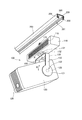
図1及び図2は、本発明を適用した実施形態に係るプロジェクター100の構成を示す図である。図1は斜視図、図2(A)は正面図、図2(B)は側面図である。これら図1及び図2の各図には、プロジェクター100が取り付けられるダクト200を合わせて図示する。   1 and 2 are diagrams showing a configuration of a projector 100 according to an embodiment to which the present invention is applied. 1 is a perspective view, FIG. 2A is a front view, and FIG. 2B is a side view. In each of these FIGS. 1 and 2, a duct 200 to which the projector 100 is attached is shown together.

プロジェクター100は、後述するように光源を内蔵し、この光源が発した光を変調して画像光とし、壁面やスクリーンに画像を投射するプロジェクターである。
プロジェクター100は、電源収容部110と、電源収容部110とは別体として構成される投射部本体120と、電源収容部110と投射部本体120とを連結する支持部材130(支持部)とを備える。電源収容部110は、細長い略箱形の筐体を有し、この筐体に、後述する電源回路24(図4)を収容する。一方、投射部本体120は、略箱形の筐体を有し、この筐体に、後述する投射部125(図3)を収容する。
As will be described later, the projector 100 is a projector that incorporates a light source, modulates light emitted from the light source into image light, and projects an image on a wall surface or a screen.
The projector 100 includes a power storage unit 110, a projection unit main body 120 that is configured separately from the power supply storage unit 110, and a support member 130 (support unit) that connects the power storage unit 110 and the projection unit main body 120. Prepare. The power supply accommodating part 110 has an elongated, substantially box-shaped casing, and a power circuit 24 (FIG. 4) described later is accommodated in the casing. On the other hand, the projection unit main body 120 has a substantially box-shaped housing, and a projection unit 125 (FIG. 3) described later is accommodated in the housing.

支持部材130は、電源収容部110の底面に、連結部131を介して連結されている。連結部131は、支持部材130の上端と電源収容部110の底面とを回動軸132を中心として回動可能に連結し、支持部材130を支持する。図中、連結部131の回動方向を矢印Aで示し、回動中心に相当する軸線を一点鎖線Aで示す。また、連結部131は、電源収容部110と支持部材130とを、任意の回動位置で固定できる。このため、電源収容部110に対して支持部材130を回動させ、投射部本体120が任意の方向を向いたところで固定できる。   The support member 130 is connected to the bottom surface of the power supply housing part 110 via the connection part 131. The connecting portion 131 supports the support member 130 by connecting the upper end of the support member 130 and the bottom surface of the power supply accommodating portion 110 so as to be rotatable about the rotation shaft 132. In the figure, the rotation direction of the connecting portion 131 is indicated by an arrow A, and the axis corresponding to the rotation center is indicated by a one-dot chain line A. Moreover, the connection part 131 can fix the power supply accommodating part 110 and the support member 130 in arbitrary rotation positions. For this reason, the support member 130 is rotated with respect to the power supply accommodating part 110, and it can fix where the projection part main body 120 has faced arbitrary directions.

連結部131は、例えば電源収容部110の筐体を構成するパネルや電源収容部110内部のフレームと、回動軸132と、回動軸132を中心とした回動を規制するように締め付け可能なボルト及びナットを用いて構成できる。また、ベアリングと、このベアリングによる回動を止めるピンと、ピンをスライドさせるスライド機構とを用いて連結部131を構成してもよい。さらに、連結部131は、リング形状の摺動部材とボルト及びナットとを組み合わせて、棒形状の回動軸132を用いない構成としてもよい。   The connecting part 131 can be tightened so as to restrict, for example, a panel constituting the casing of the power supply accommodating part 110, a frame inside the power supply accommodating part 110, a rotation shaft 132, and rotation about the rotation shaft 132. It can be configured using a simple bolt and nut. Moreover, you may comprise the connection part 131 using a bearing, the pin which stops rotation by this bearing, and the slide mechanism which slides a pin. Furthermore, the connection part 131 is good also as a structure which does not use the rod-shaped rotation axis | shaft 132 combining a ring-shaped sliding member, a volt | bolt, and a nut.

支持部材130の下部は二股に分かれて2本の腕部133、133となって下方に延びる。腕部133、133の下端には、それぞれ、平板部121、121が形成されている。平板部121、121は、それぞれ、投射部本体120の両側面に接して、連結部122、122により投射部本体120に連結される。連結部122、122は、平板部121、121と投射部本体120の側面とを回動軸123を中心として回動可能に連結し、投射部本体120を支持する。図中、連結部122、122の回動方向を矢印Bで示し、回動中心に相当する軸線を一点鎖線Bで示す。また、連結部122、122は、平板部121、121と投射部本体120とを、任意の回動位置で固定できる。このため、支持部材130に対して投射部本体120を回動させ、投射部本体120が任意の方向を向いたところで固定できる。   The lower portion of the support member 130 is divided into two forks, which become two arm portions 133 and 133 and extend downward. Flat plate portions 121 and 121 are formed at the lower ends of the arm portions 133 and 133, respectively. The flat plate portions 121 and 121 are in contact with both side surfaces of the projection unit main body 120 and are coupled to the projection unit main body 120 by the coupling units 122 and 122, respectively. The connecting portions 122 and 122 connect the flat plate portions 121 and 121 and the side surface of the projection unit main body 120 so as to be rotatable about the rotation shaft 123 and support the projection unit main body 120. In the drawing, the rotation direction of the connecting portions 122 and 122 is indicated by an arrow B, and the axis corresponding to the rotation center is indicated by a one-dot chain line B. Moreover, the connection parts 122 and 122 can fix the flat plate parts 121 and 121 and the projection part main body 120 in arbitrary rotation positions. For this reason, the projection part main body 120 can be rotated with respect to the support member 130, and it can fix when the projection part main body 120 has faced arbitrary directions.

連結部122、122は、例えば投射部本体120の筐体を構成するパネルや投射部本体120内部のフレームと、回動軸123と、回動軸123を中心とした回動を規制するように締め付け可能なボルト及びナットを用いて構成できる。また、ベアリングと、このベアリングによる回動を止めるピンと、ピンをスライドさせるスライド機構とを用いて連結部122、122を構成してもよい。さらに、連結部122、122は、リング形状の摺動部材とボルト及びナットとを組み合わせて、棒形状の回動軸123を用いない構成としてもよい。   For example, the connecting portions 122 and 122 regulate the rotation of the panel constituting the casing of the projection unit main body 120, the frame inside the projection unit main body 120, the rotation shaft 123, and the rotation shaft 123. It can be constructed using bolts and nuts that can be tightened. Moreover, you may comprise the connection parts 122 and 122 using a bearing, the pin which stops rotation by this bearing, and the slide mechanism which slides a pin. Furthermore, the connection parts 122 and 122 are good also as a structure which does not use the rod-shaped rotation axis | shaft 123 combining a ring-shaped sliding member, a volt | bolt, and a nut.

従って、プロジェクター100は、連結部131において軸線Aを中心として回動し、かつ、連結部122、122において軸線Bを中心として回動する、2軸の回動機構により、投射部本体120を支持する。   Therefore, the projector 100 supports the projection unit main body 120 by a biaxial rotation mechanism that rotates about the axis A at the connecting portion 131 and rotates about the axis B at the connecting portions 122 and 122. To do.

プロジェクター100は、天井や壁面に固定されたダクト200に接続することができる。ダクト200は、ライティングダクトと呼ばれる樋形状の電源供給体であり、例えばJIS C8366規格の照明器具用ダクト、電源用ダクト、或いは電源共用ダクトに相当する。ダクト200には、照明器具、電源供給用のアダプター等を取り付け可能である。図1には理解の便宜のため、ダクト200の断面を図示するが、ダクト200は末端が開口していなくてもよい。ダクト200は、天井面または壁面に設置されて、図示しない商用電源に接続され、上記の照明器具やアダプターに電力を供給する。   The projector 100 can be connected to a duct 200 fixed to the ceiling or wall surface. The duct 200 is a bowl-shaped power supply body called a lighting duct, and corresponds to, for example, a luminaire duct, a power supply duct, or a common power supply duct according to JIS C8366 standard. A light fixture, an adapter for supplying power, and the like can be attached to the duct 200. For convenience of understanding, FIG. 1 illustrates a cross section of the duct 200, but the end of the duct 200 may not be open. The duct 200 is installed on a ceiling surface or a wall surface, connected to a commercial power source (not shown), and supplies power to the above-described lighting fixtures and adapters.

ダクト200は、長尺形状を有する中空の本体に、長手形状に沿って延びる開口201を有し、この開口201から差し込まれるコネクター等を支持する。ダクト200が天井面に固定された場合、開口201は下向きに開口し、下方から照明器具等を取り付けて吊り下げることができる。また、ダクト200は壁面に固定してもよく、この場合、開口201は水平方向を向いて開口し、横から照明器具等を取り付けて固定できる。   The duct 200 has an opening 201 extending along the longitudinal shape in a hollow body having a long shape, and supports a connector or the like inserted from the opening 201. When the duct 200 is fixed to the ceiling surface, the opening 201 opens downward and can be suspended by attaching a lighting fixture or the like from below. Further, the duct 200 may be fixed to the wall surface. In this case, the opening 201 opens in the horizontal direction, and a lighting fixture or the like can be attached and fixed from the side.

ダクト200は、ダクト200の本体の長手方向に沿って延設された一対の導体205、205を有する。導体205、205は棒状またはテープ状に成形された銅または他の金属からなり、商用電源に電気的に接続される。導体205、205は、例えば商用の100V2極交流電源に接続され、一方の導体205が接地極となり、他方の導体205が非接地極となる。また、ダクト200は、開口201より幅の広い部材を係止する溝206、206を有する。溝206、206は、ダクト200の内部において、開口201の両側に配置され、この溝206、206に嵌合する物がダクト200によって支持される。   The duct 200 has a pair of conductors 205, 205 extending along the longitudinal direction of the main body of the duct 200. The conductors 205 and 205 are made of copper or other metal formed into a rod shape or a tape shape, and are electrically connected to a commercial power source. The conductors 205 and 205 are connected to, for example, a commercial 100V two-pole AC power source, and one conductor 205 serves as a ground electrode, and the other conductor 205 serves as a non-ground electrode. Further, the duct 200 has grooves 206 and 206 for locking a member wider than the opening 201. The grooves 206 and 206 are disposed on both sides of the opening 201 inside the duct 200, and objects fitted into the grooves 206 and 206 are supported by the duct 200.

電源収容部110は、筐体の上面に、ダクト200に連結可能なコネクター115(接続部)を有している。コネクター115は筐体の上面から上向きに突出する略円柱形状の突起であり、コネクター115の側面には、一対の係止片116、116及び一対の接触導体117、117が立設されている。
各々の係止片116、116は平板状に成形され、コネクター115から互いに反対方向に突出する。また、接触導体117、117は、銅または他の金属を平板状に成形して構成され、各々の接触導体117、117はコネクター115から互いに反対方向に突出する。
図2(A)及び(B)に示すように、係止片116と接触導体117は、コネクター115から同じ方向に突出している。すなわち、係止片116、116及び接触導体117、117は、電源収容部110の奥行き方向に突出していて、電源収容部110の筐体の長手方向に対し垂直である。
The power supply accommodating portion 110 has a connector 115 (connecting portion) that can be coupled to the duct 200 on the upper surface of the housing. The connector 115 is a substantially cylindrical protrusion that protrudes upward from the upper surface of the housing, and a pair of locking pieces 116 and 116 and a pair of contact conductors 117 and 117 are erected on the side surface of the connector 115.
Each of the locking pieces 116 and 116 is formed in a flat plate shape and protrudes from the connector 115 in the opposite directions. The contact conductors 117 and 117 are formed by forming copper or other metal into a flat plate shape, and the contact conductors 117 and 117 protrude from the connector 115 in opposite directions.
As shown in FIGS. 2A and 2B, the locking piece 116 and the contact conductor 117 protrude from the connector 115 in the same direction. That is, the locking pieces 116 and 116 and the contact conductors 117 and 117 protrude in the depth direction of the power supply accommodating portion 110 and are perpendicular to the longitudinal direction of the casing of the power supply accommodating portion 110.

プロジェクター100をダクト200に取り付ける場合、コネクター115が開口201に差し込まれる。このとき、コネクター115は、係止片116、116及び接触導体117、117がダクト200の長手方向に沿った向きで、開口201に差し入れられる。係止片116、116及び接触導体117、117がダクト200の内部に入ってから、電源収容部110を、軸線Aを中心として90度回転させると、コネクター115がダクト200に接続される。電源収容部110を回転させることにより、接触導体117、117がダクト200の導体205、205に接触して導通し、導体205、205から接触導体117、117へ電力を供給可能となる。また、係止片116、116が溝206、206に填まり込むので、係止片116、116を介してコネクター115がダクト200に固定される。この状態では、コネクター115はダクト200の長手方向にも移動しない。   When the projector 100 is attached to the duct 200, the connector 115 is inserted into the opening 201. At this time, the connector 115 is inserted into the opening 201 such that the locking pieces 116 and 116 and the contact conductors 117 and 117 are oriented along the longitudinal direction of the duct 200. When the locking pieces 116 and 116 and the contact conductors 117 and 117 enter the inside of the duct 200, the connector 115 is connected to the duct 200 when the power supply accommodating portion 110 is rotated 90 degrees about the axis A. By rotating the power supply accommodating portion 110, the contact conductors 117 and 117 are brought into contact with the conductors 205 and 205 of the duct 200 to be conducted, and power can be supplied from the conductors 205 and 205 to the contact conductors 117 and 117. Further, since the locking pieces 116 and 116 are fitted in the grooves 206 and 206, the connector 115 is fixed to the duct 200 via the locking pieces 116 and 116. In this state, the connector 115 does not move in the longitudinal direction of the duct 200.

このように、コネクター115を設けたことで、電源収容部110を容易にダクト200に取り付けることができる。この取付状態では、電源収容部110の筐体の長手方向と、ダクト200の延長方向とが一致する(平行になる)。このため、電源収容部110がダクト200と一体に見え、目立たないという利点がある。   Thus, by providing the connector 115, the power supply accommodating part 110 can be easily attached to the duct 200. FIG. In this attached state, the longitudinal direction of the casing of the power supply accommodating portion 110 and the extension direction of the duct 200 coincide (become parallel). For this reason, there exists an advantage that the power supply accommodating part 110 looks integral with the duct 200, and is not conspicuous.

プロジェクター100をダクト200に取り付けた状態では、プロジェクター100の全体がコネクター115を介してダクト200により支持される。電源収容部110においては、コネクター115の直下(真下)に、連結部131が配置されている。言い換えれば、連結部131の回動の中心軸線A上に、コネクター115が立設されている。
このため、天井面に水平に設置されたダクト200に、プロジェクター100を吊り下げるように下方から取り付けた場合、プロジェクター100の全重量が、コネクター115に対して鉛直方向の荷重として加わる。つまり、投射部本体120がどのような状態であっても、投射部本体120の重量は連結部131を介して電源収容部110に加わる。連結部131がコネクター115の直下に位置するため、投射部本体120及び支持部材130の重量は、電源収容部110の重量とともに、コネクター115に鉛直方向に作用する。従って、コネクター115に対して回転方向の力が加わらないので、係止片116、116及び接触導体117、117の一部に応力が集中する状態を回避できる。これにより、ダクト200及びコネクター115の負荷を軽減し、確実にプロジェクター100を固定できる。
In a state where the projector 100 is attached to the duct 200, the entire projector 100 is supported by the duct 200 via the connector 115. In the power supply accommodating part 110, the connection part 131 is arrange | positioned directly under the connector 115 (just under). In other words, the connector 115 is erected on the central axis A of the rotation of the connecting portion 131.
For this reason, when the projector 100 is attached to the duct 200 installed horizontally on the ceiling surface from below so as to be suspended, the total weight of the projector 100 is applied to the connector 115 as a vertical load. That is, regardless of the state of the projection unit main body 120, the weight of the projection unit main body 120 is applied to the power supply housing unit 110 via the connection unit 131. Since the connecting part 131 is located immediately below the connector 115, the weight of the projection part main body 120 and the support member 130 acts on the connector 115 in the vertical direction together with the weight of the power supply accommodating part 110. Accordingly, since no force in the rotational direction is applied to the connector 115, it is possible to avoid a state where stress is concentrated on the locking pieces 116 and 116 and part of the contact conductors 117 and 117. Thereby, the load of the duct 200 and the connector 115 can be reduced, and the projector 100 can be reliably fixed.

投射部本体120の、図2(A)に現れる正面(前面)に、投射口128が設けられている。投射口128は、投射部本体120が内蔵する投射部125(図)が画像光を放射する開口であり、レンズ等が取り付けられている。
プロジェクター100を、天井面に取り付けられたダクト200に固定すると、連結部131において支持部材130を回動させることで、投射口128の方向すなわち投射方向を、軸線Aを中心として任意の方向に変更及び調整できる。また、連結部122、122で投射部本体120を回動させることで、投射方向を、軸線Bを中心として任意の方向に変更できる。このように、プロジェクター100は、2軸を中心として、投射方向を水平及び上下に変更できるようになっている。
A projection port 128 is provided on the front surface (front surface) of the projection unit main body 120 that appears in FIG. The projection port 128 is an opening through which the projection unit 125 (FIG. 3 ) built in the projection unit main body 120 emits image light, and a lens or the like is attached thereto.
When the projector 100 is fixed to the duct 200 attached to the ceiling surface, the direction of the projection port 128, that is, the projection direction is changed to an arbitrary direction around the axis A by rotating the support member 130 at the connecting portion 131. And can be adjusted. Moreover, the projection direction can be changed to an arbitrary direction centering on the axis B by rotating the projection unit main body 120 with the coupling units 122 and 122. As described above, the projector 100 can change the projection direction horizontally and vertically around the two axes.

接触導体117、117は、コネクター115の内部に埋設された導体(図示略)を介して、電源収容部110に収容された電源回路24(図4)に接続されている。ダクト200に電源収容部110を接続すると、電源回路24(電源部)に交流100Vの電力が供給され、プロジェクター100が動作可能となる。   The contact conductors 117 and 117 are connected to a power supply circuit 24 (FIG. 4) accommodated in the power supply accommodating portion 110 via a conductor (not shown) embedded in the connector 115. When the power supply accommodating unit 110 is connected to the duct 200, AC power of 100 V is supplied to the power supply circuit 24 (power supply unit), and the projector 100 can be operated.

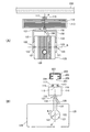
図3は、投射部本体120に収容される投射部125の構成を模式的に示す図である。
投射部125は、光源1、光変調装置3、照射光学系5、及び投射光学系6を備えている。また、光源1には、光源1を駆動する光源コントローラー2が接続され、光変調装置3には表示コントローラー4が接続されている。
FIG. 3 is a diagram schematically illustrating the configuration of the projection unit 125 accommodated in the projection unit main body 120.
The projection unit 125 includes a light source 1, a light modulation device 3, an irradiation optical system 5, and a projection optical system 6. A light source controller 2 that drives the light source 1 is connected to the light source 1, and a display controller 4 is connected to the light modulation device 3.

光源1は、R(赤色光)に対応したLEDと、G(緑色光)に対応したLEDと、B(青色光)に対応したLEDと、を備え、光源コントローラー2の制御に従って発光する。光源コントローラー2は光源1の各LEDを点灯させるパルスを出力し、光源1は入力パルスの周波数で点灯及び消灯を繰り返す。光源コントローラー2は、光源1に出力するパルスの周波数を変化させることにより各LEDの発光輝度を調整可能である。
光源1は、4つ以上の異なる要素色に対応したLEDを含んでもよいし、2つの異なる要素色に対応したLEDを含んでもよく、白色光を発する1つのLEDを備えた構成であってもよい。また、光源1は、LEDに代えて、有機または無機の半導体レーザー、または有機EL(エレクトロルミネッセント)素子を備えていてもよいし、LEDまたはレーザーを励起光源とする蛍光体を含んでいてもよい。さらにまた、光源1は、高圧水銀ランプやキセノンランプを備えていてもよい。
The light source 1 includes an LED corresponding to R (red light), an LED corresponding to G (green light), and an LED corresponding to B (blue light), and emits light according to control of the light source controller 2. The light source controller 2 outputs a pulse for turning on each LED of the light source 1, and the light source 1 is repeatedly turned on and off at the frequency of the input pulse. The light source controller 2 can adjust the light emission luminance of each LED by changing the frequency of the pulse output to the light source 1.
The light source 1 may include LEDs corresponding to four or more different element colors, may include LEDs corresponding to two different element colors, or may have a configuration including one LED that emits white light. Good. The light source 1 may include an organic or inorganic semiconductor laser or an organic EL (electroluminescent) element instead of the LED, and includes a phosphor using the LED or laser as an excitation light source. Also good. Furthermore, the light source 1 may include a high-pressure mercury lamp or a xenon lamp.

照射光学系5は、光源1が発した光を集光して、平行光として光変調装置3に照射する。照射光学系5は、ダイクロイックプリズムにより、光源1が有するつのLED(1R、1G、1B)のそれぞれからの光(光ビーム)の光路を合成する。ダイクロイックプリズムを経た光は、フライアイレンズを含んだインテグレーターにより平行光に変換される。この平行光は偏光変換素子を通って光変調装置3に照射される。
The irradiation optical system 5 condenses the light emitted from the light source 1 and irradiates the light modulation device 3 as parallel light. Irradiation optical system 5, a dichroic prism, three LED source 1 has (1R, 1G, 1B) to synthesize the optical path of the light (light beam) from each. The light passing through the dichroic prism is converted into parallel light by an integrator including a fly-eye lens. The parallel light is irradiated to the light modulation device 3 through the polarization conversion element.

光変調装置3は、単板の透過型液晶ライトバルブである。本実施形態の液晶ライトバルブは、一対の偏光板とその間に位置した液晶パネルとを含んでいる。表示コントローラー4は、光変調装置3の液晶パネルを駆動して画像を書き込む。光源1R、1G、1Bと光変調装置3とは、RGBシーケンシャル方式、すなわち色順次方式によって駆動される。そしてこのことによって、プロジェクター100はフルカラーの画像を投写し得る。
そして、光変調装置3により変調された光(画像光)は投射口128を通じて、壁やスクリーン等の投射対象面に向けて投射される。
The light modulation device 3 is a single-plate transmissive liquid crystal light valve. The liquid crystal light valve of the present embodiment includes a pair of polarizing plates and a liquid crystal panel positioned therebetween. The display controller 4 drives the liquid crystal panel of the light modulation device 3 to write an image. The light sources 1R, 1G, and 1B and the light modulation device 3 are driven by an RGB sequential method, that is, a color sequential method. As a result, the projector 100 can project a full-color image.
The light (image light) modulated by the light modulation device 3 is projected toward the projection target surface such as a wall or a screen through the projection port 128.

図4は、プロジェクター100の機能ブロック図である。
プロジェクター100は、電源収容部110に収容された電源回路24と、投射部本体120に収容された制御系の各部とを備えている。
投射部本体120に収容された制御系は、制御部23を備えている。制御部23は、図示しないCPU、ROM、RAM、不揮発性メモリー、システム・コントローラー及びその他の周辺回路等を備えている。不揮発性メモリーには、オペレーティングソフトウェアや、アプリケーションソフトウェアが記憶され、ROMにはBIOSが記憶されている。制御部23は、ROMに記憶されたBIOS、不揮発性メモリーに記憶されたオペレーティングソフトウェア及びアプリケーションソフトウェアをCPUにより実行し、制御を行う。
FIG. 4 is a functional block diagram of the projector 100.
The projector 100 includes a power supply circuit 24 accommodated in the power supply accommodating unit 110 and each part of the control system accommodated in the projection unit main body 120.
The control system accommodated in the projection unit main body 120 includes a control unit 23. The control unit 23 includes a CPU, a ROM, a RAM, a nonvolatile memory, a system controller, and other peripheral circuits (not shown). The non-volatile memory stores operating software and application software, and the ROM stores BIOS. The control unit 23 executes control by executing the BIOS stored in the ROM and the operating software and application software stored in the nonvolatile memory by the CPU.

制御部23には、バス20を介して、無線LANアダプター12、SSD(Solid State Drive)13及びメモリーカードI/O(Input/Output)回路14が接続されている。
無線LANアダプター12は、制御部23の制御に従って、無線LANの通信規格(例えばIEEE802.11)に準拠した通信を実行する。プロジェクター100は、無線LANアダプター12により図示しない外部の機器との間で無線通信を実行し、外部の機器から画像データを取得する。外部の機器としては、サーバーコンピューター、パーソナルコンピューター、タブレットコンピューター、スマートフォン、携帯電話機等の各種の機器が挙げられる。
A wireless LAN adapter 12, an SSD (Solid State Drive) 13, and a memory card I / O (Input / Output) circuit 14 are connected to the control unit 23 via a bus 20.
The wireless LAN adapter 12 executes communication conforming to a wireless LAN communication standard (for example, IEEE 802.11) according to the control of the control unit 23. The projector 100 performs wireless communication with an external device (not shown) by the wireless LAN adapter 12 and acquires image data from the external device. Examples of the external device include various devices such as a server computer, a personal computer, a tablet computer, a smartphone, and a mobile phone.

SSD13は、フラッシュメモリー素子にデータを記憶する記憶装置である。SSD13は、制御部23の制御に従って各種データを不揮発的に書き換え可能に記憶する。メモリーカードI/O回路14は、投射部本体120に設けられたメモリーカードスロット(図示略)に接続されている。メモリーカードスロット(図示略)は、例えば投射部本体120(図1)の背面に設けることができ、プロジェクター100をダクト200に取り付けた状態でカード型記憶媒体を着脱できる。メモリーカードI/O回路14は、制御部23の制御により、メモリーカードスロットに挿入されたカード型の記憶媒体(図示略)にアクセスし、この記憶媒体に記録されたデータの読み出し、及び、データの書き込みを行う。   The SSD 13 is a storage device that stores data in a flash memory element. The SSD 13 stores various data in a nonvolatile manner in accordance with the control of the control unit 23. The memory card I / O circuit 14 is connected to a memory card slot (not shown) provided in the projection unit main body 120. The memory card slot (not shown) can be provided, for example, on the rear surface of the projection unit main body 120 (FIG. 1), and the card-type storage medium can be attached and detached while the projector 100 is attached to the duct 200. The memory card I / O circuit 14 accesses a card-type storage medium (not shown) inserted into the memory card slot under the control of the control unit 23, reads out data recorded in the storage medium, and Write.

制御部23は、SSD13かメモリーカードI/O回路14により画像データを読み出して、読み出した画像データに基づく画像を投射することができる。また、制御部23は、無線LANアダプター12により外部の機器から画像データを受信し、受信した画像データに基づく画像を投射することができる。さらに、制御部23は、無線LANアダプター12により外部の機器から受信した画像データを、SSD13に記憶させてもよいし、メモリーカードI/O回路14によりカード型記憶媒体に記憶させてもよい。制御部23が処理する画像データは、静止画像データであっても、動画像(映像)データであってもよい。これらの画像データのデータフォーマット等は任意のフォーマットとすることができる。   The control unit 23 can read image data by the SSD 13 or the memory card I / O circuit 14 and project an image based on the read image data. The control unit 23 can receive image data from an external device by the wireless LAN adapter 12 and project an image based on the received image data. Further, the control unit 23 may store the image data received from the external device by the wireless LAN adapter 12 in the SSD 13 or may be stored in the card type storage medium by the memory card I / O circuit 14. The image data processed by the control unit 23 may be still image data or moving image (video) data. The data format of these image data can be any format.

制御部23には、画像処理回路21、ライトバルブ駆動回路22、光源駆動回路25、及び、IR受信回路27が接続されている。
画像処理回路21は、制御部23の制御に従って、投射する画像データを読み出して解像度変換、色調補正、台形歪み補正等の各種処理を行い、処理後の画像データを、フレーム単位でライトバルブ駆動回路22に出力する。ライトバルブ駆動回路22は、画像処理回路21から入力されるフレーム毎の画像データに従って、光変調装置3に対して液晶パネルを駆動する駆動信号を出力する。ライトバルブ駆動回路22が出力する駆動信号により、光変調装置3の液晶パネルには画像が描画され、光源1が発した光が変調される。制御部23、画像処理回路21、および、ライトバルブ駆動回路22が協働して、表示コントローラー4(図3)として機能する。
An image processing circuit 21, a light valve driving circuit 22, a light source driving circuit 25, and an IR receiving circuit 27 are connected to the control unit 23.
The image processing circuit 21 reads the image data to be projected under the control of the control unit 23 and performs various processes such as resolution conversion, color tone correction, and keystone distortion correction, and the processed image data is converted into a light valve drive circuit for each frame. 22 to output. The light valve drive circuit 22 outputs a drive signal for driving the liquid crystal panel to the light modulation device 3 according to the image data for each frame input from the image processing circuit 21. An image is drawn on the liquid crystal panel of the light modulation device 3 by the drive signal output from the light valve drive circuit 22, and the light emitted from the light source 1 is modulated. The control unit 23, the image processing circuit 21, and the light valve driving circuit 22 cooperate to function as the display controller 4 (FIG. 3).

光源駆動回路25は、制御部23の制御に従い、光源1に駆動信号を出力して点灯させる。制御部23および光源駆動回路25が協働して、光源コントローラー2(図3)として機能する。
IR受信回路27は、図示しないリモコン装置から送信される赤外線信号を受信してデコードし、リモコン装置における操作内容に対応した操作データを生成して、制御部23に出力する。
プロジェクター100の制御系を構成する無線LANアダプター12、SSD13、メモリーカードI/O回路14、画像処理回路21、ライトバルブ駆動回路22、制御部23、及びIR受信回路27の各部は、制御基板(図示略)に実装される。この制御基板は、投射部125を構成する各部とともに、投射部本体120内部のフレーム(図示略)に固定される。
The light source drive circuit 25 outputs a drive signal to the light source 1 to light up under the control of the control unit 23. The control unit 23 and the light source drive circuit 25 cooperate to function as the light source controller 2 (FIG. 3).
The IR receiving circuit 27 receives and decodes an infrared signal transmitted from a remote control device (not shown), generates operation data corresponding to the operation content in the remote control device, and outputs the operation data to the control unit 23.
The wireless LAN adapter 12, SSD 13, memory card I / O circuit 14, image processing circuit 21, light valve drive circuit 22, control unit 23, and IR receiving circuit 27 that constitute the control system of the projector 100 are controlled by a control board ( (Not shown). The control board is fixed to a frame (not shown) inside the projection unit main body 120 together with each unit constituting the projection unit 125.

電源回路24は、コネクター115に設けられた接触導体117、117から、例えば単相2極100V交流の電力の供給を受ける。電源回路24は、プロジェクター100の制御系の各部には低電圧の電源を供給する。例えば、無線LANアダプター12、SSD13、メモリーカードI/O回路14、画像処理回路21、ライトバルブ駆動回路22、制御部23、及びIR受信回路27に対し、5Vまたは3.3Vの直流電流を供給する。また、電源回路24は、より高い電圧の電力を供給可能であり、例えば、光源1が備える3つのLED、光源1を点灯させる光源駆動回路25、及び光変調装置3の液晶パネルには、12Vの直流電流を供給する。
このように、電源回路24は、プロジェクター100の各部に必要な電力を供給するため、交流―直流変換回路、トランスやスイッチング回路を備えた電圧変換回路等を備えている。
The power supply circuit 24 is supplied with electric power of, for example, single-phase two-pole 100 V AC from contact conductors 117 and 117 provided on the connector 115. The power supply circuit 24 supplies low-voltage power to each part of the control system of the projector 100. For example, a DC current of 5V or 3.3V is supplied to the wireless LAN adapter 12, SSD 13, memory card I / O circuit 14, image processing circuit 21, light valve drive circuit 22, control unit 23, and IR receiving circuit 27. To do. The power supply circuit 24 can supply higher voltage power. For example, the power supply circuit 24 has 12 LEDs for the three LEDs included in the light source 1, the light source driving circuit 25 that turns on the light source 1, and the liquid crystal panel of the light modulation device 3. DC current is supplied.
As described above, the power supply circuit 24 includes an AC-DC conversion circuit, a voltage conversion circuit including a transformer and a switching circuit, and the like in order to supply necessary power to each unit of the projector 100.

このように構成されるプロジェクター100で、支持部材130は、金属等の熱伝導率の高い材料により構成される。
また、連結部131は、電源収容部110内部の金属製のフレームに、金属製のボルトや支持軸等の熱伝導率の高い部材を介して支持部材130を連結し、電源収容部110内部で発生した熱が支持部材130に伝わる構成とすることが好ましい。或いは、電源収容部110を金属製の筐体を用いて構成し、この筐体に支持部材130が接触し、または、金属製のボルトや支持軸等を介して支持部材130が連結される構成としてもよい。
この場合、電源収容部110に収容される電源回路24が発する熱が支持部材130に伝達される。電源回路24は、発熱量の大きいトランスやスイッチング回路等を備えているため、電源収容部110の発熱量は大きい。ここで、図1及び図2(A)に示すように、電源収容部110の前面には、排熱用のスリット119が形成され、電源回路24の放熱を促進している。これに加えて、外気に露出する支持部材130に電源収容部110から熱を伝え、支持部材130の表面で放熱させることにより、電源回路24が発する熱を効率よく放熱できる。
In the projector 100 configured as described above, the support member 130 is formed of a material having high thermal conductivity such as metal.
In addition, the connecting part 131 connects the support member 130 to a metal frame inside the power supply accommodating part 110 via a member having high thermal conductivity such as a metal bolt or a support shaft. It is preferable that the generated heat is transmitted to the support member 130. Alternatively, the power supply accommodating portion 110 is configured using a metal casing, and the support member 130 is in contact with the casing, or the support member 130 is connected via a metal bolt, a support shaft, or the like. It is good.
In this case, heat generated by the power supply circuit 24 accommodated in the power supply accommodating portion 110 is transmitted to the support member 130. Since the power supply circuit 24 includes a transformer, a switching circuit, and the like that generate a large amount of heat, the heat generation amount of the power supply housing 110 is large. Here, as shown in FIG. 1 and FIG. 2A, a slit 119 for exhaust heat is formed on the front surface of the power supply accommodating portion 110 to promote heat dissipation of the power supply circuit 24. In addition, the heat generated from the power supply circuit 24 can be efficiently dissipated by transferring heat from the power supply accommodating portion 110 to the support member 130 exposed to the outside air and dissipating the heat on the surface of the support member 130.

このため、例えば、電源収容部110の内部に放熱ファンを設けることなく、電源回路24が発生する熱を十分に放熱して、電源回路24の過熱を防止し、安定してプロジェクター100を動作させることができる。電源収容部110の内部に放熱用のファンを設ける構成とすることも可能であり、この場合、支持部材130の放熱効果があるため、放熱ファンに要求される放熱量が抑制される。このため、放熱ファンを小型化したり、放熱ファンの回転数を抑えて静音化を図ったりすることができる。   For this reason, for example, the heat generated by the power supply circuit 24 is sufficiently dissipated without providing a heat radiating fan inside the power supply accommodating portion 110, thereby preventing the power supply circuit 24 from being overheated and operating the projector 100 stably. be able to. It is also possible to employ a configuration in which a heat radiating fan is provided inside the power supply accommodating portion 110. In this case, since the supporting member 130 has a heat radiating effect, the amount of heat radiated from the heat radiating fan is suppressed. For this reason, it is possible to reduce the size of the heat dissipating fan or to reduce noise by suppressing the number of rotations of the heat dissipating fan.

また、連結部122、122においても、投射部本体120内部において投射部125の各部等を支持するフレーム(図示略)に、金属製のボルトや支持軸等の熱伝導率の高い部材を介して支持部材130を連結する構成とすることが好ましい。或いは、投射部本体120を金属製の筐体を用いて構成し、この筐体に支持部材130が接触し、または、金属製のボルトや支持軸等を介して支持部材130が連結される構成としてもよい。この構成では、投射部本体120内部で発生した熱が支持部材130に伝達される。
投射部125の光源1や光変調装置3は、画像を投射する際に熱を発する。また、プロジェクター100の制御基板に実装された制御系の各部においても、プロジェクター100の動作中に熱が発生する。このため、投射部本体120の内部においては高い熱が発生する。この熱が支持部材130に伝達され、支持部材130の表面で放熱されることにより、投射部125及びプロジェクター100の制御系から発する熱を効率よく放熱できる。
Also in the connection parts 122, 122, a frame (not shown) that supports each part of the projection part 125 and the like inside the projection part main body 120 via a member having high thermal conductivity such as a metal bolt or a support shaft. It is preferable that the support member 130 be connected. Alternatively, the projection unit main body 120 is configured using a metal casing, and the support member 130 is in contact with the casing, or the support member 130 is coupled via a metal bolt, a support shaft, or the like. It is good. In this configuration, heat generated in the projection unit main body 120 is transmitted to the support member 130.
The light source 1 and the light modulation device 3 of the projection unit 125 generate heat when projecting an image. Further, heat is also generated during the operation of the projector 100 in each part of the control system mounted on the control board of the projector 100. For this reason, high heat is generated inside the projection unit main body 120. When this heat is transmitted to the support member 130 and is radiated on the surface of the support member 130, heat generated from the projection system 125 and the control system of the projector 100 can be efficiently radiated.

これにより、例えば、投射部本体120に放熱ファンを設けることなく、投射部125や制御基板の熱を十分に放熱して、これらの各部の過熱を防止し、安定してプロジェクター100を動作させることができる。また、投射部本体120の内部に放熱用のファンを設ける構成とすることも可能であり、この場合、支持部材130の放熱効果があるため、放熱ファンに要求される放熱量が抑制される。このため、放熱ファンを小型化したり、放熱ファンの回転数を抑えて静音化を図ったりすることができる。   Thereby, for example, without providing a heat radiating fan in the projection unit main body 120, the heat of the projection unit 125 and the control board can be sufficiently radiated to prevent overheating of these units and to stably operate the projector 100. Can do. In addition, it is possible to provide a heat dissipation fan inside the projection unit main body 120. In this case, since the support member 130 has a heat dissipation effect, the heat dissipation required for the heat dissipation fan is suppressed. For this reason, it is possible to reduce the size of the heat dissipating fan or to reduce noise by suppressing the number of rotations of the heat dissipating fan.

以上説明したように、本発明を適用した実施形態に係るプロジェクター100は、電源収容部110と投射部本体120とを備える。電源収容部110は、ダクト200に支持され、ダクト200から供給される電力を変換する電源回路24を収容し、投射部本体120は画像を投射する投射部125を収容し、画像の投射方向を調整可能に電源収容部110に支持される。この構成において投射方向を変更する場合には投射部本体120を動かせばよく、この投射部本体120は電源回路24が分離されているため軽量である。また、電源回路24は、上記のようにトランスやスイッチング回路を有する他、これらの回路から適切に放熱させるためのヒートシンク等を備えている。このため、電源回路24は重量物となるが、この電源回路24を投射部本体120から分離したため、投射方向を変更する場合に重量物である電源回路24を動かす必要がない。   As described above, the projector 100 according to the embodiment to which the present invention is applied includes the power supply accommodation unit 110 and the projection unit main body 120. The power storage unit 110 is supported by the duct 200 and stores the power supply circuit 24 that converts the power supplied from the duct 200. The projection unit main body 120 stores the projection unit 125 that projects an image, and changes the projection direction of the image. It is supported by the power supply accommodating part 110 so that adjustment is possible. In this configuration, when the projection direction is changed, the projection unit main body 120 may be moved, and the projection unit main body 120 is lightweight because the power supply circuit 24 is separated. Further, the power supply circuit 24 includes a transformer and a switching circuit as described above, and also includes a heat sink for appropriately radiating heat from these circuits. For this reason, although the power supply circuit 24 is heavy, since the power supply circuit 24 is separated from the projection unit main body 120, it is not necessary to move the heavy power supply circuit 24 when changing the projection direction.

そして、投射部本体120を支持する連結部131及び連結部122、122は、電源回路24を除く部分の重量を支持し、固定できるものであればよい。このように、連結部131及び連結部122、122の負荷が軽減され、耐荷重に関する制限が緩和されているので、連結部131及び連結部122、122の設計の自由度が高まる。例えば、投射部125の角度等を大きく変更可能な構造とすることができる。さらに、電源収容部110がダクト200に支持されるので、電源収容部110がダクト200から電力を得るためのケーブル等を別途設ける必要がなく、構造を簡略化でき、強固に電源収容部110を保持できる。従って、天井面等に強固に取り付けることが可能で、かつ、画像の投射方向を容易に、大きく調整可能なプロジェクター100を提供できる。   And the connection part 131 and the connection parts 122 and 122 which support the projection part main body 120 should just support the weight of the part except the power supply circuit 24, and can fix. Thus, since the load of the connection part 131 and the connection parts 122 and 122 is reduced and the restriction on the load resistance is relaxed, the degree of freedom in designing the connection part 131 and the connection parts 122 and 122 is increased. For example, it can be set as the structure which can change the angle etc. of the projection part 125 largely. Furthermore, since the power supply accommodating part 110 is supported by the duct 200, it is not necessary to separately provide a cable or the like for the power accommodating part 110 to obtain electric power from the duct 200, the structure can be simplified, and the power supply accommodating part 110 can be firmly fixed. Can hold. Therefore, it is possible to provide the projector 100 that can be firmly attached to a ceiling surface or the like and can easily adjust the image projection direction easily.

また、電源収容部110は、長手形状の筐体と、筐体に立設されて樋形状のダクト200に接続されるコネクター115とを有し、筐体がダクト200の長手方向に沿う状態でコネクター115がダクト200に固定される。このため、いわゆる照明器具用ダクトや電源ダクト等の樋形状のダクト200に、電源収容部110を取り付けることができ、ダクト200の長手方向においてプロジェクターの取付位置を容易に変更できる。また、電源収容部110の筐体がダクト200の長手方向に沿っているため、目立たないようにプロジェクター100を取り付けることができる。
また、プロジェクター100は、電源収容部110と投射部本体120とに連結され、投射部本体120を電源収容部110に支持する支持部材130を有する。支持部材130は電源収容部110において、コネクター115の直下で連結部131により接続される。このため、コネクター115に加わる荷重が、ほぼ垂直方向の荷重に限られるので、コネクター115に加わる負荷を軽減できるので、コネクター115を簡易な構造とすることができる。
In addition, the power supply accommodating portion 110 has a longitudinal casing and a connector 115 that is erected on the casing and connected to the bowl-shaped duct 200, and the casing is in a state along the longitudinal direction of the duct 200. Connector 115 is fixed to duct 200. For this reason, the power supply accommodating part 110 can be attached to the bowl-shaped duct 200 such as a so-called lighting fixture duct or a power supply duct, and the attachment position of the projector can be easily changed in the longitudinal direction of the duct 200. Further, since the casing of the power supply accommodating portion 110 is along the longitudinal direction of the duct 200, the projector 100 can be attached so as not to be noticeable.
In addition, the projector 100 includes a support member 130 that is connected to the power storage unit 110 and the projection unit main body 120 and supports the projection unit main body 120 to the power supply storage unit 110. The support member 130 is connected by the connecting portion 131 in the power supply accommodating portion 110 immediately below the connector 115. For this reason, since the load applied to the connector 115 is limited to the load in the substantially vertical direction, the load applied to the connector 115 can be reduced, so that the connector 115 can have a simple structure.

また、支持部材130は、電源収容部110及び投射部本体120の少なくともいずれかに対し、熱を伝達可能に、連結部131または連結部122、122により連結される。このため、支持部材130により、電源収容部110内部の電源回路24が発する熱や、投射部本体120内部の投射部125等が発する熱を放熱できる。従って、プロジェクター100における放熱性能を高めることができ、プロジェクター100を安定して動作させることが可能な上に、冷却ファンの小型化や冷却ファンを省略することが可能になる。   Further, the support member 130 is connected to at least one of the power supply housing part 110 and the projection part main body 120 by the connection part 131 or the connection parts 122 and 122 so that heat can be transferred. For this reason, the support member 130 can dissipate heat generated by the power supply circuit 24 inside the power supply accommodating portion 110 and heat generated by the projection portion 125 and the like inside the projection portion main body 120. Therefore, the heat dissipation performance of the projector 100 can be improved, the projector 100 can be operated stably, and the cooling fan can be downsized and the cooling fan can be omitted.

また、投射部本体120に光源1が収容されるので、電源収容部110と投射部本体120とを連結する構成を簡易化でき、例えば投射部本体120の可動範囲を大きくすることができる。   Further, since the light source 1 is accommodated in the projection unit main body 120, the configuration for connecting the power supply accommodation unit 110 and the projection unit main body 120 can be simplified, and for example, the movable range of the projection unit main body 120 can be increased.

ここで、電源収容部110に光源1を収容した構成とすることもできる。この場合、投射部125は、電源収容部110に収容された光源1と、光源1が発した光を投射部本体120の内部に導く光ファイバー等のライトガイド(導光手段)とを備え、このライトガイドにより導かれた光が、照射光学系5を経て光変調装置3に導かれる。この構成では、光源1を電源収容部110に備えることにより、投射部本体120をより一層軽量化することが可能となる。これにより、投射部本体120を支持する連結部131及び連結部122、122の負荷がより軽減され、設計の自由度が高められるので、投射部125の角度等を大きく変更可能な構造とすることができる。   Here, a configuration in which the light source 1 is accommodated in the power supply accommodating portion 110 may be adopted. In this case, the projection unit 125 includes the light source 1 housed in the power supply housing unit 110, and a light guide (light guide unit) such as an optical fiber that guides light emitted from the light source 1 to the inside of the projection unit body 120. The light guided by the light guide is guided to the light modulation device 3 through the irradiation optical system 5. In this configuration, by providing the light source 1 in the power supply housing 110, the projection unit main body 120 can be further reduced in weight. Thereby, since the load of the connection part 131 and the connection parts 122 and 122 which support the projection part main body 120 is further reduced, and the freedom degree of design is raised, it is set as the structure which can change the angle etc. of the projection part 125 largely. Can do.

なお、上述した実施形態は、あくまでも本発明の一態様を示すものであり、本発明の範囲内で任意に変形および応用が可能である。
上記実施形態では、電源収容部110と投射部本体120とを連結し、投射部本体120を支持する支持部として支持部材130を用いた構成について説明した。本発明はこれに限定されず、例えば、投射部本体120に対し一箇所で連結される部材を用いてもよい。具体的には、投射部本体120の上面と電源収容部110の底面とに、対になるジョイントを立設して、これらのジョイントを連結してもよく、より具体的にはボールジョイントやユニバーサルジョイントを用いてもよい。また、所定の軸回りに回動可能な関節状のジョイントを複数備えた支持部材を用いてもよい。また、電源収容部110及び投射部本体120の形状は箱形に限定されず、例えば投射部本体120を球形とすることも可能である。さらに、支持部材130の放熱効果を高めるため、支持部材130の表面に複数の放熱フィンを形成してもよい。
In addition, embodiment mentioned above shows the one aspect | mode of this invention to the last, and a deformation | transformation and application are arbitrarily possible within the scope of the present invention.
In the above-described embodiment, the configuration in which the power supply accommodation unit 110 and the projection unit main body 120 are connected and the support member 130 is used as a support unit that supports the projection unit main body 120 has been described. The present invention is not limited to this, and for example, a member connected to the projection unit main body 120 at one place may be used. Specifically, a pair of joints may be erected on the upper surface of the projection unit main body 120 and the bottom surface of the power supply housing unit 110, and these joints may be connected. A joint may be used. Further, a support member provided with a plurality of articulated joints that can rotate around a predetermined axis may be used. Moreover, the shape of the power supply accommodating part 110 and the projection part main body 120 is not limited to a box shape, For example, the projection part main body 120 can also be made into a spherical shape. Furthermore, a plurality of heat radiation fins may be formed on the surface of the support member 130 in order to enhance the heat dissipation effect of the support member 130.

また、図4に示した各機能ブロックはハードウェアとソフトウェアとの協働により実現される機能的構成を示すものであって、具体的な実装形態は特に制限されない。従って、必ずしも各機能ブロックに対応するハードウェアが実装される必要はなく、一つのプロセッサーがプログラムを実行することで複数の機能部の機能を実現する構成とすることも勿論可能である。また、上記実施形態においてソフトウェアで実現されている機能の一部をハードウェアで実現してもよく、あるいは、ハードウェアで実現されている機能の一部をソフトウェアで実現してもよい。その他、プロジェクター100の他の各部の具体的な細部構成についても、本発明の趣旨を逸脱しない範囲で任意に変更可能である。   Each functional block shown in FIG. 4 shows a functional configuration realized by cooperation of hardware and software, and a specific mounting form is not particularly limited. Accordingly, hardware corresponding to each functional block is not necessarily installed, and it is of course possible to realize a configuration in which a function of a plurality of functional units is realized by one processor executing a program. In addition, in the above embodiment, a part of the function realized by software may be realized by hardware, or a part of the function realized by hardware may be realized by software. In addition, the specific detailed configuration of each other part of the projector 100 can be arbitrarily changed without departing from the gist of the present invention.

1…光源、3…光変調装置、5…照射光学系、6…投射光学系、23…制御部、24…電源回路(電源部)、100…プロジェクター、110…電源収容部、115…コネクター(接続部)、120…投射部本体、125…投射部、130…支持部材(支持部)、131…連結部、140…電源収容部本体、200…ダクト(電源供給体)。   DESCRIPTION OF SYMBOLS 1 ... Light source, 3 ... Light modulation apparatus, 5 ... Irradiation optical system, 6 ... Projection optical system, 23 ... Control part, 24 ... Power supply circuit (power supply part), 100 ... Projector, 110 ... Power supply accommodating part, 115 ... Connector ( Connection unit), 120 ... Projection unit body, 125 ... Projection unit, 130 ... Support member (support unit), 131 ... Connection unit, 140 ... Power supply housing unit body, 200 ... Duct (power supply body)

Claims (4)

長手形状の電源供給体に固定される接続部を有し、前記接続部を介して前記電源供給体に支持され、前記電源供給体から供給される電力を変換する電源部を収容した電源収容部と、
画像を投射する投射部を収容し、前記画像の投射方向を調整可能に前記電源収容部に支持される投射部本体と、
前記電源供給体に固定される前記接続部の直下に配置された連結部を介して前記電源収容部に連結され、前記投射部本体に連結され、前記投射部本体を前記電源収容部に支持する支持部と、を備え、
前記投射部本体は、光源を含む投射部及び制御部を収容し、
前記電源部は、直流−交流変換回路を備え、前記電源供給体から供給される交流電力を変換して、前記制御部に第1電圧の直流電力を供給し、前記光源に、前記第1電圧の直流電流より高い第2電圧の直流電力を供給することを特徴とするプロジェクター。
A power supply housing portion having a connection portion fixed to a longitudinal power supply body, and supported by the power supply body via the connection portion and housing a power supply portion for converting power supplied from the power supply body When,
A projection unit main body that accommodates a projection unit that projects an image, and is supported by the power source accommodation unit so that the projection direction of the image can be adjusted;
Wherein coupled to the power supply accommodating section via the arranged connecting portion directly below the connecting portion which is fixed to the power supply member, is connected to the projecting portion present body supporting the projecting portion main body to the power receiving portion And a support part
The projection unit body accommodates a projection unit and a control unit including a light source,
The power supply unit includes a DC-AC conversion circuit, converts AC power supplied from the power supply body, supplies DC power of a first voltage to the control unit, and supplies the first voltage to the light source. A projector that supplies DC power of a second voltage higher than the DC current of the projector.
前記電源収容部は、長手形状の筐体を有し前記接続部は前記筐体に立設されて樋形状の前記電源供給体に接続され、前記筐体が前記電源供給体の長手方向に沿う状態で前記接続部が前記電源供給体に固定されること、を特徴とする請求項1記載のプロジェクター。 The power receiving unit includes a housing longitudinally extending, the connecting portion is connected to the power supply of the trough shape is erected in the housing, the longitudinal direction of the housing the power supply body The projector according to claim 1, wherein the connection portion is fixed to the power supply body along the line. 前記支持部は、前記電源収容部内の金属製のフレームに金属製の部材を介して連結され、前記電源収容部から熱を伝達可能に連結されること、を特徴とする請求項1または2記載のプロジェクター。   The said support part is connected with the metal frame in the said power supply accommodating part via a metal member, and is connected so that heat can be transmitted from the said power supply accommodating part. Projector. 前記電源部は、前記直流−交流変換回路、及び、トランス或いはスイッチング回路を備える電圧変換回路を含むことを特徴とする請求項1からのいずれかに記載のプロジェクター。
The power supply unit, the DC - AC converter, and projector according to any one of claims 1 to 3, characterized in that it comprises a voltage conversion circuit with a transformer or switching circuit.
JP2013150129A 2013-07-19 2013-07-19 projector Expired - Fee Related JP6322916B2 (en)

Priority Applications (4)

Application Number Priority Date Filing Date Title
JP2013150129A JP6322916B2 (en) 2013-07-19 2013-07-19 projector
US14/330,222 US9405176B2 (en) 2013-07-19 2014-07-14 Projector with adjustable support
CN201410342372.2A CN104298054B (en) 2013-07-19 2014-07-17 Projector
US15/182,064 US9874804B2 (en) 2013-07-19 2016-06-14 Projector with adjustable support

Applications Claiming Priority (1)

Application Number Priority Date Filing Date Title
JP2013150129A JP6322916B2 (en) 2013-07-19 2013-07-19 projector

Publications (3)

Publication Number Publication Date
JP2015022147A JP2015022147A (en) 2015-02-02
JP2015022147A5 JP2015022147A5 (en) 2016-08-12
JP6322916B2 true JP6322916B2 (en) 2018-05-16

Family

ID=52486647

Family Applications (1)

Application Number Title Priority Date Filing Date
JP2013150129A Expired - Fee Related JP6322916B2 (en) 2013-07-19 2013-07-19 projector

Country Status (1)

Country Link
JP (1) JP6322916B2 (en)

Families Citing this family (2)

* Cited by examiner, † Cited by third party
Publication number Priority date Publication date Assignee Title
JP6701873B2 (en) * 2016-03-28 2020-05-27 セイコーエプソン株式会社 projector
JP2018084685A (en) 2016-11-24 2018-05-31 株式会社リコー Image projection device and image projection system

Family Cites Families (19)

* Cited by examiner, † Cited by third party
Publication number Priority date Publication date Assignee Title
JPH0216516U (en) * 1988-07-18 1990-02-02
JPH08180975A (en) * 1994-12-21 1996-07-12 Matsushita Electric Works Ltd Lighting system using thermal infrared-ray detecting unit
JPH113045A (en) * 1997-06-10 1999-01-06 Victor Co Of Japan Ltd Projection type display device
JPH11102161A (en) * 1997-09-28 1999-04-13 Victor Co Of Japan Ltd Projection type display device and its ceiling installation device
US6179426B1 (en) * 1999-03-03 2001-01-30 3M Innovative Properties Company Integrated front projection system
GB2389726B (en) * 2002-02-16 2004-09-08 Alan Maddock An adaptor for portable visual display permitting user attachment and configuration of accessories and media
JP4101571B2 (en) * 2002-07-04 2008-06-18 株式会社日立製作所 Projection type image display device support device
JP2004126381A (en) * 2002-10-04 2004-04-22 Sony Corp Picture display device
JP2004184768A (en) * 2002-12-04 2004-07-02 Kanebo Ltd Projector device
JP2004233692A (en) * 2003-01-30 2004-08-19 Dainippon Printing Co Ltd Projector device
JP2004336615A (en) * 2003-05-12 2004-11-25 Plus Vision Corp Projector and mounting device therefor
JP2005099588A (en) * 2003-09-26 2005-04-14 Sanyo Electric Co Ltd Projection type image display system and connector device
JP2006084765A (en) * 2004-09-16 2006-03-30 Canon Inc Projection-type display device
JP2006227143A (en) * 2005-02-16 2006-08-31 Seiko Epson Corp Projector
JP2007047577A (en) * 2005-08-11 2007-02-22 Nikon Corp Support device for projector and projection system
JP5082981B2 (en) * 2008-03-27 2012-11-28 セイコーエプソン株式会社 projector
JP5367437B2 (en) * 2009-04-13 2013-12-11 株式会社内田洋行 Lighting fixture and lighting system
JP6008074B2 (en) * 2011-08-10 2016-10-19 三菱電機株式会社 lighting equipment
JP5871156B2 (en) * 2011-09-29 2016-03-01 カシオ計算機株式会社 Projector suspension member, projector, and projector mounting method

Also Published As

Publication number Publication date
JP2015022147A (en) 2015-02-02

Similar Documents

Publication Publication Date Title
US9874804B2 (en) Projector with adjustable support
JP6322917B2 (en) projector
US10012893B2 (en) Image projection apparatus
US9864262B2 (en) Image projection device and image projection method to control an illumination area based on movement of image generating unit
JP5354288B2 (en) projector
US20210208490A1 (en) Projection device and projection lens
JP5083590B2 (en) Projection-side optical system and projector
US9411216B2 (en) Projector with intake ducts provided in a case thereof
JP6322916B2 (en) projector
US20220091491A1 (en) Projection device
JP2006308885A (en) Projector
JP6321148B2 (en) Projection display device
US9778551B2 (en) Illumination optical system, optical engine, and image projection apparatus
JP2020077003A (en) projector
JP6550834B2 (en) projector
US20200278106A1 (en) Led lighting apparatus
WO2014207935A1 (en) Projection type image display device
JP2006208831A (en) Projector
JP6507899B2 (en) Image projection device
JP2019040110A (en) projector
JP2008218148A (en) Illuminating device
JP2007273442A (en) Remote-controlled luminaire and lighting system
KR20120123819A (en) Lamp assembly
TWM530382U (en) Lamp
JP2014075218A (en) Lighting fixture

Legal Events

Date Code Title Description
A521 Request for written amendment filed

Free format text: JAPANESE INTERMEDIATE CODE: A523

Effective date: 20160627

A621 Written request for application examination

Free format text: JAPANESE INTERMEDIATE CODE: A621

Effective date: 20160627

A977 Report on retrieval

Free format text: JAPANESE INTERMEDIATE CODE: A971007

Effective date: 20170324

A131 Notification of reasons for refusal

Free format text: JAPANESE INTERMEDIATE CODE: A131

Effective date: 20170404

A521 Request for written amendment filed

Free format text: JAPANESE INTERMEDIATE CODE: A523

Effective date: 20170602

A131 Notification of reasons for refusal

Free format text: JAPANESE INTERMEDIATE CODE: A131

Effective date: 20171114

A521 Request for written amendment filed

Free format text: JAPANESE INTERMEDIATE CODE: A523

Effective date: 20180111

TRDD Decision of grant or rejection written
A01 Written decision to grant a patent or to grant a registration (utility model)

Free format text: JAPANESE INTERMEDIATE CODE: A01

Effective date: 20180313

A61 First payment of annual fees (during grant procedure)

Free format text: JAPANESE INTERMEDIATE CODE: A61

Effective date: 20180326

R150 Certificate of patent or registration of utility model

Ref document number: 6322916

Country of ref document: JP

Free format text: JAPANESE INTERMEDIATE CODE: R150

LAPS Cancellation because of no payment of annual fees