JP6320755B2 - Obesity hypoventilation syndrome treatment system and method - Google Patents
Obesity hypoventilation syndrome treatment system and method Download PDFInfo
- Publication number
- JP6320755B2 JP6320755B2 JP2013539379A JP2013539379A JP6320755B2 JP 6320755 B2 JP6320755 B2 JP 6320755B2 JP 2013539379 A JP2013539379 A JP 2013539379A JP 2013539379 A JP2013539379 A JP 2013539379A JP 6320755 B2 JP6320755 B2 JP 6320755B2
- Authority
- JP
- Japan
- Prior art keywords
- breath
- subject
- pressure
- spontaneous
- module
- Prior art date
- Legal status (The legal status is an assumption and is not a legal conclusion. Google has not performed a legal analysis and makes no representation as to the accuracy of the status listed.)
- Active
Links
Images


Classifications
-
- A—HUMAN NECESSITIES
- A61—MEDICAL OR VETERINARY SCIENCE; HYGIENE
- A61M—DEVICES FOR INTRODUCING MEDIA INTO, OR ONTO, THE BODY; DEVICES FOR TRANSDUCING BODY MEDIA OR FOR TAKING MEDIA FROM THE BODY; DEVICES FOR PRODUCING OR ENDING SLEEP OR STUPOR
- A61M16/00—Devices for influencing the respiratory system of patients by gas treatment, e.g. mouth-to-mouth respiration; Tracheal tubes
- A61M16/0057—Pumps therefor
- A61M16/0066—Blowers or centrifugal pumps
- A61M16/0069—Blowers or centrifugal pumps the speed thereof being controlled by respiratory parameters, e.g. by inhalation
-
- A—HUMAN NECESSITIES
- A61—MEDICAL OR VETERINARY SCIENCE; HYGIENE
- A61M—DEVICES FOR INTRODUCING MEDIA INTO, OR ONTO, THE BODY; DEVICES FOR TRANSDUCING BODY MEDIA OR FOR TAKING MEDIA FROM THE BODY; DEVICES FOR PRODUCING OR ENDING SLEEP OR STUPOR
- A61M16/00—Devices for influencing the respiratory system of patients by gas treatment, e.g. mouth-to-mouth respiration; Tracheal tubes
- A61M16/021—Devices for influencing the respiratory system of patients by gas treatment, e.g. mouth-to-mouth respiration; Tracheal tubes operated by electrical means
- A61M16/022—Control means therefor
- A61M16/024—Control means therefor including calculation means, e.g. using a processor
-
- A—HUMAN NECESSITIES
- A61—MEDICAL OR VETERINARY SCIENCE; HYGIENE
- A61M—DEVICES FOR INTRODUCING MEDIA INTO, OR ONTO, THE BODY; DEVICES FOR TRANSDUCING BODY MEDIA OR FOR TAKING MEDIA FROM THE BODY; DEVICES FOR PRODUCING OR ENDING SLEEP OR STUPOR
- A61M16/00—Devices for influencing the respiratory system of patients by gas treatment, e.g. mouth-to-mouth respiration; Tracheal tubes
- A61M16/10—Preparation of respiratory gases or vapours
- A61M16/14—Preparation of respiratory gases or vapours by mixing different fluids, one of them being in a liquid phase
- A61M16/16—Devices to humidify the respiration air
- A61M16/161—Devices to humidify the respiration air with means for measuring the humidity
-
- A—HUMAN NECESSITIES
- A61—MEDICAL OR VETERINARY SCIENCE; HYGIENE
- A61M—DEVICES FOR INTRODUCING MEDIA INTO, OR ONTO, THE BODY; DEVICES FOR TRANSDUCING BODY MEDIA OR FOR TAKING MEDIA FROM THE BODY; DEVICES FOR PRODUCING OR ENDING SLEEP OR STUPOR
- A61M16/00—Devices for influencing the respiratory system of patients by gas treatment, e.g. mouth-to-mouth respiration; Tracheal tubes
- A61M16/10—Preparation of respiratory gases or vapours
- A61M16/105—Filters
- A61M16/106—Filters in a path
- A61M16/1065—Filters in a path in the expiratory path
-
- A—HUMAN NECESSITIES
- A61—MEDICAL OR VETERINARY SCIENCE; HYGIENE
- A61M—DEVICES FOR INTRODUCING MEDIA INTO, OR ONTO, THE BODY; DEVICES FOR TRANSDUCING BODY MEDIA OR FOR TAKING MEDIA FROM THE BODY; DEVICES FOR PRODUCING OR ENDING SLEEP OR STUPOR
- A61M16/00—Devices for influencing the respiratory system of patients by gas treatment, e.g. mouth-to-mouth respiration; Tracheal tubes
- A61M16/0003—Accessories therefor, e.g. sensors, vibrators, negative pressure
- A61M2016/0015—Accessories therefor, e.g. sensors, vibrators, negative pressure inhalation detectors
- A61M2016/0018—Accessories therefor, e.g. sensors, vibrators, negative pressure inhalation detectors electrical
- A61M2016/0021—Accessories therefor, e.g. sensors, vibrators, negative pressure inhalation detectors electrical with a proportional output signal, e.g. from a thermistor
-
- A—HUMAN NECESSITIES
- A61—MEDICAL OR VETERINARY SCIENCE; HYGIENE
- A61M—DEVICES FOR INTRODUCING MEDIA INTO, OR ONTO, THE BODY; DEVICES FOR TRANSDUCING BODY MEDIA OR FOR TAKING MEDIA FROM THE BODY; DEVICES FOR PRODUCING OR ENDING SLEEP OR STUPOR
- A61M16/00—Devices for influencing the respiratory system of patients by gas treatment, e.g. mouth-to-mouth respiration; Tracheal tubes
- A61M16/0003—Accessories therefor, e.g. sensors, vibrators, negative pressure
- A61M2016/0027—Accessories therefor, e.g. sensors, vibrators, negative pressure pressure meter
-
- A—HUMAN NECESSITIES
- A61—MEDICAL OR VETERINARY SCIENCE; HYGIENE
- A61M—DEVICES FOR INTRODUCING MEDIA INTO, OR ONTO, THE BODY; DEVICES FOR TRANSDUCING BODY MEDIA OR FOR TAKING MEDIA FROM THE BODY; DEVICES FOR PRODUCING OR ENDING SLEEP OR STUPOR
- A61M16/00—Devices for influencing the respiratory system of patients by gas treatment, e.g. mouth-to-mouth respiration; Tracheal tubes
- A61M16/0003—Accessories therefor, e.g. sensors, vibrators, negative pressure
- A61M2016/003—Accessories therefor, e.g. sensors, vibrators, negative pressure with a flowmeter
- A61M2016/0033—Accessories therefor, e.g. sensors, vibrators, negative pressure with a flowmeter electrical
- A61M2016/0039—Accessories therefor, e.g. sensors, vibrators, negative pressure with a flowmeter electrical in the inspiratory circuit
-
- A—HUMAN NECESSITIES
- A61—MEDICAL OR VETERINARY SCIENCE; HYGIENE
- A61M—DEVICES FOR INTRODUCING MEDIA INTO, OR ONTO, THE BODY; DEVICES FOR TRANSDUCING BODY MEDIA OR FOR TAKING MEDIA FROM THE BODY; DEVICES FOR PRODUCING OR ENDING SLEEP OR STUPOR
- A61M16/00—Devices for influencing the respiratory system of patients by gas treatment, e.g. mouth-to-mouth respiration; Tracheal tubes
- A61M16/10—Preparation of respiratory gases or vapours
- A61M16/1005—Preparation of respiratory gases or vapours with O2 features or with parameter measurement
- A61M2016/102—Measuring a parameter of the content of the delivered gas
-
- A—HUMAN NECESSITIES
- A61—MEDICAL OR VETERINARY SCIENCE; HYGIENE
- A61M—DEVICES FOR INTRODUCING MEDIA INTO, OR ONTO, THE BODY; DEVICES FOR TRANSDUCING BODY MEDIA OR FOR TAKING MEDIA FROM THE BODY; DEVICES FOR PRODUCING OR ENDING SLEEP OR STUPOR
- A61M2205/00—General characteristics of the apparatus
- A61M2205/33—Controlling, regulating or measuring
- A61M2205/3365—Rotational speed
-
- A—HUMAN NECESSITIES
- A61—MEDICAL OR VETERINARY SCIENCE; HYGIENE
- A61M—DEVICES FOR INTRODUCING MEDIA INTO, OR ONTO, THE BODY; DEVICES FOR TRANSDUCING BODY MEDIA OR FOR TAKING MEDIA FROM THE BODY; DEVICES FOR PRODUCING OR ENDING SLEEP OR STUPOR
- A61M2205/00—General characteristics of the apparatus
- A61M2205/33—Controlling, regulating or measuring
- A61M2205/3368—Temperature
-
- A—HUMAN NECESSITIES
- A61—MEDICAL OR VETERINARY SCIENCE; HYGIENE
- A61M—DEVICES FOR INTRODUCING MEDIA INTO, OR ONTO, THE BODY; DEVICES FOR TRANSDUCING BODY MEDIA OR FOR TAKING MEDIA FROM THE BODY; DEVICES FOR PRODUCING OR ENDING SLEEP OR STUPOR
- A61M2205/00—General characteristics of the apparatus
- A61M2205/33—Controlling, regulating or measuring
- A61M2205/3375—Acoustical, e.g. ultrasonic, measuring means
-
- A—HUMAN NECESSITIES
- A61—MEDICAL OR VETERINARY SCIENCE; HYGIENE
- A61M—DEVICES FOR INTRODUCING MEDIA INTO, OR ONTO, THE BODY; DEVICES FOR TRANSDUCING BODY MEDIA OR FOR TAKING MEDIA FROM THE BODY; DEVICES FOR PRODUCING OR ENDING SLEEP OR STUPOR
- A61M2205/00—General characteristics of the apparatus
- A61M2205/50—General characteristics of the apparatus with microprocessors or computers
- A61M2205/502—User interfaces, e.g. screens or keyboards
- A61M2205/505—Touch-screens; Virtual keyboard or keypads; Virtual buttons; Soft keys; Mouse touches
-
- A—HUMAN NECESSITIES
- A61—MEDICAL OR VETERINARY SCIENCE; HYGIENE
- A61M—DEVICES FOR INTRODUCING MEDIA INTO, OR ONTO, THE BODY; DEVICES FOR TRANSDUCING BODY MEDIA OR FOR TAKING MEDIA FROM THE BODY; DEVICES FOR PRODUCING OR ENDING SLEEP OR STUPOR
- A61M2230/00—Measuring parameters of the user
- A61M2230/40—Respiratory characteristics
- A61M2230/43—Composition of exhalation
-
- A—HUMAN NECESSITIES
- A61—MEDICAL OR VETERINARY SCIENCE; HYGIENE
- A61M—DEVICES FOR INTRODUCING MEDIA INTO, OR ONTO, THE BODY; DEVICES FOR TRANSDUCING BODY MEDIA OR FOR TAKING MEDIA FROM THE BODY; DEVICES FOR PRODUCING OR ENDING SLEEP OR STUPOR
- A61M2230/00—Measuring parameters of the user
- A61M2230/60—Muscle strain, i.e. measured on the user
-
- A—HUMAN NECESSITIES
- A61—MEDICAL OR VETERINARY SCIENCE; HYGIENE
- A61M—DEVICES FOR INTRODUCING MEDIA INTO, OR ONTO, THE BODY; DEVICES FOR TRANSDUCING BODY MEDIA OR FOR TAKING MEDIA FROM THE BODY; DEVICES FOR PRODUCING OR ENDING SLEEP OR STUPOR
- A61M2230/00—Measuring parameters of the user
- A61M2230/62—Posture
-
- A—HUMAN NECESSITIES
- A61—MEDICAL OR VETERINARY SCIENCE; HYGIENE
- A61M—DEVICES FOR INTRODUCING MEDIA INTO, OR ONTO, THE BODY; DEVICES FOR TRANSDUCING BODY MEDIA OR FOR TAKING MEDIA FROM THE BODY; DEVICES FOR PRODUCING OR ENDING SLEEP OR STUPOR
- A61M2230/00—Measuring parameters of the user
- A61M2230/63—Motion, e.g. physical activity
Description
本特許出願は、米国特許法第119条(e)項に基づいて2010年11月23日に出願された米国仮出願第61/416336号の優先権利益を主張し、その内容は、参照によりここに組み込まれる。 This patent application claims priority benefit of US Provisional Application No. 61 / 416,336 filed on November 23, 2010 under section 119 (e) of the US Patent Act, the contents of which are incorporated by reference Incorporated here.
本発明は、平均一回換気量、呼吸速度、及び/又は呼気終末陽圧が自動的に制御される、呼吸器疾患を治療する対象に対する治療の供給に関する。 The present invention relates to the delivery of treatment to a subject treating a respiratory disease in which the average tidal volume, respiratory rate, and / or positive end expiratory pressure are automatically controlled.
肥満低換気症候群は、肥満した対象(例えば、30kg/m2以上の肥満度指数を持つ対象)が浅い又は不十分な呼吸から生じる低酸素症及び高炭酸症を患う呼吸器症候群である。他の症候群又は状態は、これら及び/又は他の症状を持つ。呼吸を容易化するようにこのような対象の気道に加圧ガスを供給するように構成されたシステムが、既知である。このようなシステムは、治療的呼吸速度及び呼吸ごとの平均一回換気量を維持するように構成されたシステムを有する。 Obesity hypoventilation syndrome is a respiratory syndrome in which obese subjects (eg, subjects with a body mass index of 30 kg / m 2 or greater) suffer from hypoxia and hypercapnia resulting from shallow or inadequate breathing. Other syndromes or conditions have these and / or other symptoms. Systems are known that are configured to deliver pressurized gas to the airways of such subjects to facilitate breathing. Such systems have a system configured to maintain therapeutic respiratory rate and average tidal volume per breath.
従来のシステムにおいて、治療的呼吸速度は、ユーザ(例えば、対象、介護士、治療決定者、研究者、及び/又は他のユーザ)により設定される設定でありうる。このようなシステムにおいて、治療的呼吸速度は、対象による自発呼吸の測定を考慮に入れない。 In conventional systems, the therapeutic respiratory rate can be a setting set by a user (eg, subject, caregiver, treatment decision maker, researcher, and / or other user). In such a system, the therapeutic respiratory rate does not take into account the measurement of spontaneous breathing by the subject.
典型的には、平均一回換気量を維持するシステムにおいて、呼吸ごとに、同じ圧力レベルでサポートされる。これらのシステムは、一般に、自発的及び非自発的呼吸を異なる圧力レベルでサポートするように構成されない。 Typically, in systems that maintain average tidal volume, each breath is supported at the same pressure level. These systems are generally not configured to support spontaneous and involuntary breathing at different pressure levels.
したがって、本発明の目的は、従来のシステムの欠点を克服する治療システムを提供することである。 Accordingly, it is an object of the present invention to provide a treatment system that overcomes the shortcomings of conventional systems.
この目的は、対象の気道に呼吸可能ガスの加圧流を供給するシステムを提供することにより本発明の一実施例によって達成される。一実施例において、前記システムは、圧力発生器、センサ及び1つ又は複数のプロセッサを有する。前記圧力発生器は、対象の気道に供給する呼吸可能ガスの加圧流を発生する。前記センサは、前記対象による呼吸努力に関する情報を伝える出力信号を発生する。前記1つ又は複数のプロセッサは、制御モジュール、吸気圧モジュール、速度決定モジュール及び呼気圧モジュールを含むコンピュータプログラムモジュールを実行する。前記制御モジュールは、平均一回換気量が前記対象に対するブレス中に維持されるように、及び前記ブレスが呼吸速度で生じるように治療レジメンによって前記圧力発生器を制御する。前記吸気圧モジュールは、平均一回換気量を維持する吸気圧レベルを決定する。前記速度決定モジュールは、治療的呼吸速度を決定する。前記呼気圧モジュールは、呼気圧レベルを決定する。前記制御モジュールは、前記対象による呼吸が前記治療的呼吸速度に維持されるように、及び吸気中に呼吸可能ガスの加圧流が前記吸気圧モジュールにより決定される吸気圧レベルで供給され、呼気中に呼吸可能ガスの加圧流が前記呼気圧レベルで供給されるように、前記圧力発生器を制御する。 This object is achieved by an embodiment of the present invention by providing a system for supplying a pressurized flow of breathable gas to a subject's airway. In one embodiment, the system includes a pressure generator, a sensor, and one or more processors. The pressure generator generates a pressurized flow of breathable gas that is supplied to the airway of interest. The sensor generates an output signal that conveys information about respiratory effort by the subject. The one or more processors execute computer program modules including a control module, an inspiratory pressure module, a speed determination module, and an expiratory pressure module. Wherein the control module, so that the average tidal volume is maintained in the breath for the target, and the breath to control the pressure generator by treatment regimen to occur at breath rate. The intake pressure module determines an intake pressure level that maintains an average tidal volume. The rate determination module determines a therapeutic respiratory rate. The expiratory pressure module determines an expiratory pressure level. The control module is supplied such that breathing by the subject is maintained at the therapeutic respiratory rate, and a pressurized flow of breathable gas during inspiration is provided at an inspiratory pressure level determined by the inspiratory pressure module. The pressure generator is controlled such that a pressurized flow of breathable gas is supplied at the expiratory pressure level.
本開示の他の態様は、対象の気道に対して呼吸可能ガスの加圧流を供給する方法に関する。一実施例において、前記方法は、対象の気道に供給する呼吸可能ガスの加圧流を発生するステップと、前記対象による呼吸努力に関する情報を伝える出力信号を発生するステップと、平均一回換気量を維持する吸気圧レベルを動的に決定するステップと、呼気圧レベルを動的に決定するステップと、治療的呼吸速度を動的に決定するステップと、前記対象の呼吸が前記治療的呼吸速度で生じるように、及び吸気中に前記呼吸可能ガスの加圧流が前記吸気圧モジュールにより決定された前記吸気圧レベルで供給され、呼気中に前記呼吸可能ガスの加圧流が前記呼気圧レベルで供給されるように、治療レジメンによって前記呼吸可能ガスの加圧流の発生を制御するステップとを有する。 Another aspect of the present disclosure relates to a method of supplying a pressurized flow of breathable gas to a subject's airway. In one embodiment, the method includes the steps of generating a pressurized flow of breathable gas to supply to a subject's airway, generating an output signal conveying information about breathing effort by the subject, and average tidal volume. Dynamically determining an inspiratory pressure level to maintain; dynamically determining an expiratory pressure level; dynamically determining a therapeutic respiration rate; and wherein the subject's respiration is at the therapeutic respiration rate A pressurized flow of the breathable gas is supplied at the inspiratory pressure level determined by the inspiratory pressure module, and a pressurized flow of the breathable gas is supplied at the expiratory pressure level during expiration. Controlling the generation of a pressurized flow of the breathable gas with a treatment regimen.
本発明の他の態様は、対象の気道に呼吸可能ガスの加圧流を供給するシステムに関する。一実施例において、前記システムは、対象の気道に供給する呼吸可能ガスの加圧流を発生する手段と、前記対象による呼吸努力に関する情報を伝える出力信号を発生する手段と、平均一回換気量を維持する吸気圧レベルを動的に決定する手段と、呼気圧レベルを動的に決定する手段と、治療的呼吸速度を動的に決定する手段と、前記対象の呼吸が前記治療的呼吸速度で生じるように、及び吸気中に前記呼吸可能ガスの加圧流が前記吸気圧モジュールにより決定された前記吸気圧レベルで供給され、呼気中に前記呼吸可能ガスの加圧流が前記呼気圧レベルで供給されるように、治療レジメンによって前記呼吸可能ガスの加圧流の発生を制御する手段とを有する。 Another aspect of the invention relates to a system for providing a pressurized flow of breathable gas to a subject's airway. In one embodiment, the system includes means for generating a pressurized flow of breathable gas to supply to a subject's airway, means for generating an output signal conveying information regarding breathing effort by the subject, and average tidal volume. Means for dynamically determining an inspiratory pressure level to maintain; means for dynamically determining an expiratory pressure level; means for dynamically determining a therapeutic respiration rate; and respiration of the subject at the therapeutic respiration rate A pressurized flow of the breathable gas is supplied at the inspiratory pressure level determined by the inspiratory pressure module, and a pressurized flow of the breathable gas is supplied at the expiratory pressure level during expiration. And means for controlling the generation of a pressurized flow of the breathable gas by a treatment regimen.
本発明のこれら及び他の目的、フィーチャ及び特徴、並びに動作の方法及び構造の関連した要素の機能及び部品の組み合わせ及び製造の経済性は、全て本明細書の一部であり、同様の参照番号が様々な図において対応する部分を示す添付の図面を参照して以下の記載及び添付の請求項を検討すると明らかになる。本発明の一実施例において、ここに示される構成成分は、比例して描かれる。しかしながら、図面は図示及び説明の目的のみであり、本発明の限定ではないと明確に理解されるべきである。加えて、ここでいずれの実施例に示される又は記載される構造的フィーチャが、他の実施例でも同様に使用されることができると理解されるべきである。しかしながら、図面が図示及び説明の目的のみであり、本発明の限定の規定として意図されないと明確に理解されるべきである。 These and other objects, features and characteristics of the present invention, as well as the function of the related elements of the method and structure of operation and the economics of the combination and manufacture of parts, are all part of this specification and similar reference numbers are used. Will become apparent from a consideration of the following description and the appended claims, taken in conjunction with the accompanying drawings, which illustrate corresponding parts in the various figures. In one embodiment of the present invention, the components shown herein are drawn proportionately. However, it should be clearly understood that the drawings are for purposes of illustration and description only and are not a limitation of the present invention. In addition, it should be understood that the structural features shown or described herein in any embodiment can be used in other embodiments as well. However, it should be clearly understood that the drawings are for purposes of illustration and description only and are not intended as limitations of the invention.
ここで使用される、"ある"及び"その"の単数形は、文脈が明らかに別に指示しない限り複数形を含む。ここで使用される、2つ以上の部分又は構成要素が"結合"されるという記述は、前記部分が、直接的に又は間接的に、すなわちリンクが存在する限り1つ又は複数の中間部分又は構成要素を介してのいずれかで一緒に結び付けられる又は動作することを意味するべきである。ここで使用される、"直接的に結合される"は、2つの要素が互いに直接的に接触していることを意味する。ここで使用される、"固定して結合される"又は"固定される"は、2つの構成要素が互いに対して一定の向きを維持しながら1つのものとして移動するように結合されることを意味する。 As used herein, the singular form “a” and “the” includes the plural unless the context clearly dictates otherwise. As used herein, a statement that two or more parts or components are “coupled” means that the part is directly or indirectly, ie one or more intermediate parts or as long as there is a link It should mean tied or operating together either via a component. As used herein, “directly coupled” means that the two elements are in direct contact with each other. As used herein, “fixedly coupled” or “fixed” means that two components are coupled so that they move as one while maintaining a fixed orientation relative to each other. means.
ここで使用される、単語"ユニタリ"は、構成要素が単一のピース又はユニットとして作成されることを意味する。すなわち、別々に作成され、ユニットして一緒に結合されたピースを含む構成要素は、"ユニタリ"構成要素又はボディではない。ここで使用される、2つ以上の部分又は構成要素が互いに"係合"するという記述は、前記部分が直接的に又は1つ若しくは複数の中間部分若しくは構成要素を介して互いに対して力を及ぼすことを意味すべきである。ここで使用される、用語"数"は、1又は1より大きい整数(すなわち、複数)を意味すべきである。 As used herein, the word “unitary” means that the component is created as a single piece or unit. That is, components that include pieces that are created separately and united together are not “unitary” components or bodies. As used herein, a statement that two or more parts or components “engage” each other means that the parts directly or against one another via one or more intermediate parts or components. Should mean to effect. As used herein, the term “number” should mean one or an integer greater than one (ie, a plurality).
例えば、これらに限定されないが、最上部、底部、左、右、上、下、前、後ろ及びこれらの波生物のような、ここで使用される方向の表現は、図面に示される要素の向きに関し、明示的に記載されない限り請求項を限定しない。 For example, but not limited to, top, bottom, left, right, top, bottom, front, back, and directional representations as used herein are orientations of elements shown in the drawings. The claims are not limited unless explicitly stated.
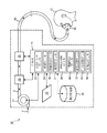
図1は、治療レジメンによって対象12の気道に呼吸可能ガスの加圧流を供給するシステム10を示す。前記治療レジメンは、肥満低換気症候群(OHS)、閉塞性睡眠時無呼吸(OSA)及び/又は他の呼吸状態のような呼吸状態を治療するように設計されることができる。前記治療レジメンは、平均一回換気量の維持、呼吸速度の維持、及び/又は呼気終末陽圧の維持を指示する。システム10は、対象12が治療的呼吸速度で呼吸することを保証するように、対象12として対象12に治療を提供する。前記呼吸速度は、治療セッションの早い段階の対象12の呼吸に基づいて、及び/又は前記対象の検出された覚醒状態に基づいて動的に決定されることができる。システム10は、自発的ブレスが、自発的ではなく前記治療的呼吸速度に基づいて自動的にトリガされるブレスに対する圧力より低い圧力でサポートされることができるように構成されることができる。一実施例において、システム10は、1つ又は複数の圧力発生器14、電子記憶部16、ユーザインタフェース18、1つ又は複数のセンサ20、プロセッサ24、及び/又は他の構成要素を含む。
FIG. 1 illustrates a
一実施例において、圧力発生器14は、対象12の気道に供給する呼吸可能ガスの加圧流を発生する。圧力発生器14は、治療目的又は他の目的で呼吸可能ガスの加圧流の1つ又は複数のパラメータ(例えば、流量、圧力、体積、湿度、温度、ガス組成等)を制御することができる。前記1つ又は複数のパラメータは、(例えば以下に論じられるように)治療レジメンによって制御されることができる。前記治療レジメンは、対象12のクオリティオブライフを持続及び/又は改良するように構成されることができる。非限定的な例として、圧力発生器14は、呼吸不全又は気道閉塞症候群を治療するために呼吸可能ガスの加圧流の圧力を制御するように構成されることができる。前記圧力発生器は、対象12に気道陽圧治療を提供する陽圧発生器を含むことができる。このような装置は、例えば、参照により全体的にここに組み込まれる、米国特許第6105575号に記載されている。
In one embodiment, the
前記呼吸可能ガスの加圧流は、インタフェース26を介して対象12の気道に供給される。インタフェース26は、圧力発生器14により発生された呼吸可能ガスの加圧流を対象12の気道に伝える。このようなものとして、インタフェース26は、導管28及びインタフェース器具30を含む。導管は、前記呼吸可能ガスの加圧流をインタフェース器具30に伝え、インタフェース器具30は、前記呼吸可能ガスの加圧流を対象12の気道に供給する。インタフェース器具30のいくつかの例は、例えば、気管内チューブ、鼻カニューレ、鼻マスク、鼻/口マスク、フルフェイスマスク、トータルフェイスマスク、又は対象の気道にガスの流れを伝える他のインタフェース器具を含むことができる。本発明は、これらの例に限定されず、いかなる対象インタフェースを使用する対象12に対する前記呼吸可能ガスの加圧流の供給も検討する。
The pressurized flow of breathable gas is supplied to the airway of the subject 12 via the interface 26. The interface 26 communicates the pressurized flow of breathable gas generated by the
図1は、シングルリムのパッシブシステムであるインタフェース26を持つシステム10の構成を示すが、これは、限定することを意図されない。本開示の範囲は、インタフェース26がインタフェース器具30から呼気を受け取る第2の導管を含む2リムシステムとして形成される実施例を含むと理解される。前記第2の導管は、このような流体を大気に排出してもよく、このような流体をフィルタに伝えてもよく、及び/又はこのような流体をシステム10内の構成要素を含む他の構成要素に伝えてもよい。
Although FIG. 1 shows the configuration of a
一実施例において、電子記憶部16は、情報を電子的に記憶する電子記憶媒体を有する。電子記憶部16の前記電子記憶媒体は、システム10と一体的に提供される(すなわち実質的に取り外し可能ではない)システム記憶部、及び/又は例えばポート(例えばUSBポート、ファイヤワイヤポート等)又はドライブ(例えば、ディスクドライブ等)を介してシステム10に取り外し可能に接続可能である取り外し可能記憶部の一方又は両方を含むことができる。電子記憶部16は、光読み取り可能記憶媒体(例えば、光ディスク等)、磁気読み取り可能記憶媒体(例えば、磁気テープ、磁気ハードドライブ、フロッピー(登録商標)ドライブ等)、電荷ベース記憶媒体(例えば、EEPROM、RAM等)、半導体記憶媒体(例えば、フラッシュドライブ等)、及び/又は他の電子読み取り可能記憶媒体の1つ又は複数を含むことができる。電子記憶部16は、ソフトウェアアルゴリズム、プロセッサ24により決定される情報、ユーザインタフェース18を介して受信される情報、及び/又はシステム10が適切に機能することを可能にする他の情報を記憶することができる。電子記憶部16は、(全体的に又は部分的に)システム10内の別の構成要素であってもよく、又は電子記憶部16は、(全体的に又は部分的に)システム10の1つ又は複数の他の構成要素(例えば、発生器14、ユーザインタフェース18、プロセッサ24党)と一体化して設けられてもよい。
In one embodiment, the
ユーザインタフェース18は、システム10と1人又は複数のユーザ(例えば、対象12、介護士、研究者、治療決定者等)との間のインタフェースを提供し、これを介して、前記ユーザは、システム10に情報を提供し、システム10から情報を受信することができる。これは、まとめて"情報"と称される、データ、キュー、結果、及び/又は命令及び他の通信可能なアイテムが、前記ユーザと、圧力発生器14、電子記憶部16及び/又はプロセッサ24の1つ又は複数との間で通信されることを可能にする。ユーザインタフェース18に含めるのに適したインタフェース装置の例は、キーパッド、ボタン、スイッチ、キーボード、ノブ、レバー、表示画面、タッチスクリーン、スピーカ、マイクロフォン、インジケータ光、可聴アラーム、プリンタ、触覚フィードバック装置及び/又は他のインタフェース装置を含む。一実施例において、ユーザインタフェース18は、複数の別のインタフェースを含む。一実施例において、ユーザインタフェース18は、発生器14と一体化して設けられる少なくとも1つのインタフェースを含む。ユーザインタフェース18は、システム10の調整可能パラメータを修正するように対象12から入力を受信することができる。例えば、ユーザインタフェース18は、呼吸状態検出の感度又は応答時間を修正又は選択するように対象12から入力を受信することができる(例えば、呼吸状態遷移検出に対する閾値が、段階的ノブ又は1から10までの数を表示するデジタルインタフェースを用いて感度の増加又は減少のいずれかに対して調整されることができる)。
The
ハードワイヤード又はワイヤレスのいずれかの他の通信技術も、ユーザインタフェース18として本発明により考えられると注意すべきである。例えば、本発明は、ユーザインタフェース18が、電子記憶部16により提供される取り外し可能記憶インタフェースと一体化されることができると考える。この例において、情報は、前記ユーザがシステム10の実施をカスタマイズすることを可能にする取り外し可能記憶部(例えば、スマートカード、フラッシュドライブ、取り外し可能ディスク等)からシステム10にロードされることができる。システム10とともに使用するのに適した他の模範的な入力装置及び技術は、RS−232ポート、RFリンク、IRリンク、モデム(電話、ケーブル又は他)を含むが、これらに限定されない。要するに、システム10と情報を通信するいかなる技術も、本発明によりユーザインタフェース18として考えられる。
It should be noted that other communication technologies, either hardwired or wireless, are also contemplated by the present invention as
センサ20は、対象12の呼吸努力に関する情報を伝える1つ又は複数の出力信号を発生する。一実施例において、センサ20は、前記呼吸可能ガスの加圧流の1つ又は複数の流体パラメータに関する情報を伝える出力信号を発生する。前記1つ又は複数のパラメータは、例えば、流量、体積、圧力、組成(例えば、1つ又は複数の成分の濃度)、湿度、温度、加速度、速度、音響特性、呼吸を示すパラメータの変化、及び/又は他の流体パラメータの1つ又は複数を含むことができる。一実施例において、センサ20は、流量センサ及び圧力センサである。前記センサは、このようなパラメータを直接的に(例えば、圧力発生器14又は対象インタフェース26における前記呼吸可能ガスの加圧流での流体連通により)測定する1つ又は複数のセンサを含むことができる。センサ20は、間接的に前記呼吸可能ガスの加圧流の1つ又は複数の流体パラメータに関する出力信号を発生する1つ又は複数のセンサを含むことができる。例えば、センサ20の1つ又は複数は、圧力発生器14及び/又は他のセンサの動作パラメータ(例えば、バルブドライバ又はモータ電流、電圧、回転速度、及び/又は他の動作パラメータ)に基づいて出力を発生することができる。
The
呼吸努力に関する情報を伝える他の出力信号が考えられる。例えば、センサ20は、呼吸筋努力を機械的に検出するセンサ(例えば、対象12の胸部の周りのバンド上で着用される)、対象12の画像を取得する及び/又は対象12の位置及び/又は運動(例えば、速度又は加速度)を測定する光センサを含むことができる。
Other output signals that convey information about respiratory effort are possible. For example, the
センサ20は、圧力発生器14に隣接して配置された2つの別のセンサとして図示されるが、これは、限定的であることを意図されない。前記センサは、例えば、圧力発生器14内に、導管28内に(連通して)、インタフェース器具30内で(連通して)、及び/又は他の場所のような、単一の場所又は複数の場所に配置された1つ又は複数のセンサを含みる。
Although
一部の実施例において、センサ20の1つ又は複数は、システム10の外側に、及び対象12のより近くに配置されることができる。このような実施例において、外部に配置されたセンサ20により発生された出力信号は、有線及び/又は無線構成によりプロセッサ24に中継されることができる。独立なユーザインタフェースは、センサ20により発生された出力信号を受信し、ここに記載された技術の一部又は全てを実施して前記出力信号を処理し、及び/又は前記決定された情報の少なくとも一部を表示する外部に配置されたセンサ20とともに含められる。
In some embodiments, one or more of the
プロセッサ24は、システム10において情報処理能力を提供する。このようなものとして、プロセッサ24は、デジタルプロセッサ、アナログプロセッサ、情報を処理するように設計されたデジタル回路、情報を処理するように設計されたアナログ回路、状態機械、及び/又は情報を電子的に処理する他の機構の1つ又は複数を含むことができる。プロセッサ24は、図1において単一のエンティティとして示されているが、これは、説明目的のみである。一部の実施例において、プロセッサ24は、複数の処理ユニットを含むことができる。これらの処理ユニットは、同じ装置(例えば、圧力発生器14)内に物理的に配置されてもよく、又はプロセッサ24は、協調して動作する複数の装置の処理機能を表することができる。
The
一般に、プロセッサ24は、対象12の呼吸状態を決定するように構成される。プロセッサ24は、前記呼吸可能ガスの加圧流の1つ又は複数のパラメータが、呼吸状態に応じて前記1つ又は複数のパラメータを規定する治療レジメンによって異なるように前記呼吸可能ガスの加圧流の発生において圧力発生器14を制御するように構成される。呼吸状態を検出するために、プロセッサ24は、前記呼吸可能ガスの加圧流の流れの形状(及び/又は他の流体パラメータ)に基づいて呼吸状態の遷移を識別するように構成されることができる。呼吸状態の遷移の識別は、対象12の気道(例えば、インタフェース器具30)における又は近くの流体パラメータの感知及び/又は推定とは独立でありうる。このようなものとして、正確な漏れ及び/又は損失推定を必要としない。一部の実施例において、プロセッサ24は、流れの一次時間導関数の変化に基づいて呼吸状態の遷移を識別するように構成されることができる。
In general, the
図1に示されるように、プロセッサ24は、1つ又は複数のコンピュータプログラムモジュールを実行するように構成されることができる。前記1つ又は複数のコンピュータプログラムモジュールは、流体パラメータモジュール32、制御モジュール34、体積決定モジュール36、吸気圧モジュール37、自発的呼吸モジュール38、覚醒検出モジュール40、速度決定モジュール42、ブースト決定モジュール44、呼気圧モジュール46、及び/又は他のモジュールの1つ又は複数を含むことができる。プロセッサ24は、モジュール32、34、36、37、38、40、42、44及び/又は46を、ソフトウェア、ハードウェア、ファームウェア、ソフトウェア、ハードウェア及び/又はファームウェアの組み合わせ、及び/又はプロセッサ24上で処理能力を構成する他の機構により実行するように構成されることができる。
As shown in FIG. 1, the
モジュール32、34、36、37、38、40、42、44及び46が図1において単一の処理ユニット内に共同配置されて図示されるが、プロセッサ24が複数の処理ユニットを含む実施例において、モジュール32、34、36、37、38、40、42、44及び/又は46の1つ又は複数が、他のモジュールから離れて配置されることができると理解されるべきである。以下に記載される異なるモジュール32、34、36、37、38、40、42、44及び/又は46により提供される機能の説明は、説明目的であり、限定的であることを意図されず、モジュール32、34、36、37、38、40、42、44及び/又は46のいずれかが、記載されるより多い又は少ない機能を提供することができる。例えば、モジュール32、34、36、37、38、40、42、44及び/又は46の1つ又は複数は、消去されてもよく、その機能の一部又は全ては、モジュール32、34、36、37、38、40、42、44及び/又は46の他のものにより提供されることができる。他の例として、プロセッサ24は、モジュール32、34、36、37、38、40、42、44及び/又は46の1つに属する機能の一部又は全てを実行することができる1つ又は複数の追加のモジュールを実行するように構成されることができる。
Although
流体パラメータモジュール32は、前記呼吸可能ガスの加圧流の1つ又は複数の流体パラメータを決定するように構成される。流体パラメータモジュール32は、センサ20により発生された出力信号に基づいて前記呼吸可能ガスの加圧流の前記1つ又は複数の流体パラメータを決定する。呼吸パラメータモジュール32により決定される前記1つ又は複数の流体パラメータは、流量、体積、圧力、組成(例えば、1つ又は複数の成分の濃度)、湿度、温度、加速度、速度、音響特性、呼吸を示すパラメータの変化、及び/又は他の流体パラメータを含むことができる。
The
制御モジュール34は、治療レジメンによって前記呼吸可能ガスの加圧流の前記パラメータを調整するように圧力発生器14を制御するように構成される。前記治療レジメンは、対象12の平均一回換気量が維持され、前記対象の呼吸速度が維持されることができる、及び/又は前記対象の呼気終末陽圧が維持されることができるように対象12の気道に前記呼吸可能ガスの加圧流を提供する。前記治療レジメンは、AVAPS、ACV及び/又は他の体積治療を含むことができる及び/又は関連することができる。このタイプの治療は、対象12の気道がサポートされるが、一回換気量及び/又は呼吸速度が維持されない、気道陽圧(PAP)治療のような圧力サポート治療とは異なる。代わりに、PAP治療は、典型的には、一回換気量及び/又は呼吸速度を考慮せずに気道の構造的適正を所定のレベルに維持するように圧力を制御するのみである。
The
制御モジュール34により提供される前記治療レジメンは、二層治療である。この治療レジメンにおいて、呼気中の前記呼吸可能ガスの加圧流の圧力のレベルは、(呼気気道陽圧又はEPAPとして知られる)呼気レベルに維持される。吸気中に、前記呼吸可能ガスの加圧流の圧力レベルは、対象12が前記平均一回換気量を維持するのに十分なガスを取り込むことを保証するように増加される。吸気気道陽圧(IPAP)とEPAPとの間の変化は、呼吸速度によってトリガされる。前記呼吸速度によるブレスは、自発的ブレス(例えば、対象12が自発的に吸気中にガスを肺に取り込み、及び/又は自発的に呼気中に肺からガスを排出するブレス)と、非自発的ブレス(例えば、ガスの運動が、全体的に(又は実質的に)前記呼吸可能ガスの加圧流の圧力のレベルの変化によるブレス)を含む。
The treatment regimen provided by the
体積決定モジュール36は、対象12に対する前記呼吸可能ガスの加圧流の供給中にブレスの一回換気量をモニタリングするように構成される。これは、個別のブレスの一回換気量を決定すること、複数のブレスに対する平均一回換気量を決定すること、時間のスライドウィンドウに対する平均一回換気量を決定すること、及び/又は他の一回換気量を決定することを含むことができる。前記一回換気量の決定は、流体パラメータモジュール32により決定された1つ又は複数の流体パラメータ及び/又はセンサ20により出力された出力信号に基づいてなされることができる。
The
吸気圧モジュール37は、IPAPのベースラインレベルを決定するように構成される。前記吸気圧モジュールは、対象12の呼吸の平均一回換気量が目標平均一回換気量に維持されるように前記IPAPのベースラインレベルを決定するように構成される。前記目標平均一回換気量は、対象12、介護士、治療決定者、研究者、及び/又は他のユーザからのシステム10に対する入力に基づいて決定されることができる。一実施例において、前記IPAPのベースラインレベルに対する変化は、変化の最大レートにより制限される。前記変化の最大レートは、約3cmH2O/分以上でありうる。これは、従来のAVAPS及び/又はACV治療システムより高速でありうる。前記IPAPのベースラインレベルに対するこのより動的な制御は、身体位置をシフトする対象12により引き起こされる呼吸の変化に対してより迅速に調整することにより対象12の快適性を向上させうる。
The
自発的呼吸モジュール38は、対象12により行われる自発的ブレスを識別するように構成される。自発的ブレスの識別は、センサ20により発生された出力信号に基づく。一実施例において、このような識別は、センサ20により発生された出力信号から流体パラメータモジュール32により決定された1つ又は複数の流体パラメータに基づく。
覚醒検出モジュール40は、治療セッション中の対象12の覚醒を検出するように構成される。一実施例において、対象12の覚醒は、自発的呼吸モジュール38による自発的ブレスの識別に基づいて決定される。睡眠中に、対象12は、より少ない自発的ブレスを持つ傾向にある。したがって、覚醒検出モジュール40は、自発的ブレスの増加に基づいて覚醒を検出することができる。自発的ブレスの増加は、自発的ブレスが生じる速度を閾値レベルと比較することにより、時間のスライドウィンドウ中の自発的ブレスの量を閾値量と比較することにより識別され、及び/又は他の技術により識別されることができる。一実施例において、センサ20は、対象12の運動に関する情報を伝える1つ又は複数のセンサを含む。覚醒検出モジュール40は、ユーザインタフェース20により示される対象12の運動に基づいて覚醒を検出するように構成されることができる。覚醒を検出する他の機構が考えられる。
速度決定モジュール42は、IPAPとEPAPとの間の遷移をトリガするのに使用される前記治療的呼吸速度を決定するように構成される。従来のAVAPS及び/又はACV治療システムにおいて、前記呼吸速度は、主に又は単に、対象12、介護士、治療決定者、研究者、及び/又は他のユーザにより入力される速度に基づいて決定されることができる。これに反して、速度決定モジュール42は、対象12による自発的呼吸に基づいて前記呼吸速度を決定するように構成される。速度決定モジュール42は、治療セッションの早期に(例えば、夜の開始時に)対象12の前記呼吸速度を評価し、前記治療セッションを通して適切に前記呼吸速度を維持する。呼吸速度を動的に決定し、(例えば、吸気圧モジュール37により決定されたIPAPレベルを用いて)一回換気量を制御することにより、対象12の分時換気量は、間接的に維持されることができる。
The
呼気の終わりに、ゼロに近い流量が対象12の気道において観測され、肺が一定の体積のままである、1つの完全なブレスサイクルと同じくらい長く続きうる高度に可変の時間期間が存在する。時々、呼気中断と称される、この期間は、心理学者及び医師の両方により研究されている。これは、呼吸器系の筋肉に対する休息期間として機能し、過剰な酸素の増大を防ぎ、左心室が満たされる間の動脈血圧安定化をも可能にする。対象12に対する呼吸の労力を減少するシステム10により提供される機械式換気のサポートとともに、拡張された休息期間は、必要ではない。更に、対象12の通常の支援されないガス交換速度は、血流のCO2レベルを適切に減少するのに不十分である場合に、呼気終末中断を短縮することにより睡眠中に呼吸速度を調整する利益が存在することができる。本質的には、システム10は、中枢神経系の前にブレスを開始することにより高炭酸ガス症の対象12の化学療法需要可能機構をリードするようにプログラムされる。
At the end of expiration, near zero flow is observed in the airway of subject 12, and there is a highly variable time period that can last as long as one complete breath cycle, with the lungs remaining at a constant volume. This period, sometimes referred to as exhalation, has been studied by both psychologists and physicians. This serves as a rest period for the respiratory muscles, prevents excessive oxygen buildup and also allows arterial blood pressure stabilization while the left ventricle is filled. With the mechanical ventilation support provided by the
一実施例において、前記治療的呼吸速度を決定する速度決定モジュール42により実施されるアルゴリズムは、対象12の早期の及び最速の自発的呼吸速度をシードとして実施する。自発的ブレス時間の繰り返すウィンドウが、メモリ(例えば、電子記憶部16)に維持される。前記ウィンドウは、12ないし50のブレスを含むことができる。一実施例において、前記ウィンドウは、約30のブレスを含む。ブレス時間は、適格である場合に前記ウィンドウに入力される。ブレスは、(1)呼気段階から吸気段階まで前記装置を自発的にトリガした患者努力とともに開始および終了され、(2)前記ブレス中の提供された一回換気量が典型的な一回換気量に近かった(例えば、所定量内)場合に"適格"であると速度決定モジュール42により見なされる。第2の適格因子は、迅速な浅い回復ブレスが、高すぎる前記治療的呼吸速度を人工的に設定することを防ぐ。(設定された平均体積ではなく)典型的な一回換気量は、最大又は最小IPAP圧力設定が体積設定に適していない場合を可能にするのに使用される。この適格要件は、自動バックアップアルゴリズムに対する前例を取るのに適切なIPAPレベルの決定及び供給をも可能にする。
In one embodiment, the algorithm implemented by the
速度決定モジュール42は、前記記憶されたウィンドウにおけるブレス時間から現在の平均自発的ブレス時間を決定するように構成される。覚醒ブレス時間は、(A)前記現在の平均自発的ブレス時間が最小値(例えば、所定の、ユーザ設定可能な、製造時に決定された、動的に決定された、及び/又は他の形で決定された最小値)である又はそれより上である場合、及び(B)少なくとも閾値割合の前記ブレスが自発的である場合に、前記現在の平均自発的ブレス時間に等しく設定される。前記閾値割合は、変化しない割合であってもよく、又は治療セッションの途中に変化してもよい。例えば、前記治療セッションの開始時に、対象12は目が覚めており、比較的警戒しているので、前記閾値割合は、比較的高い値(例えば、100%)でありうる。前記治療セッションが進行すると(及び/又は対象12の覚醒状態及び/又は注意力が衰えると)、前記閾値割合は、例えば、約70%のような、より低い値に減少されることができる。前記閾値割合の減少は、徐々の減少、傾斜した減少、高い値から低い値への切り替え、及び/又は値を減少する他の技術を含むことができる。
速度決定モジュール42は、覚醒ブレス時間に基づいて治療的ブレス時間を設定するように構成される。一実施例において、前記治療的ブレス時間は、速度決定モジュール42により、前記覚醒ブレス時間の1.14倍の時間又は前記覚醒ブレス時間に対応する呼吸速度より毎分2ブレス少ない呼吸速度に対応する時間の小さい方に設定される。前記治療的ブレス時間を決定するこの実施例は、以下の関係式、
(1) TBT=lesser_of(1.14×WBT, 60/((60/WBT)-2))
により示され、ここでTBTは、前記治療的ブレス時間を表し、WBTは、前記覚醒ブレス時間を表す。
The
(1) TBT = lesser_of (1.14 × WBT, 60 / ((60 / WBT) -2))
Where TBT represents the therapeutic breath time and WBT represents the wake-up breath time.
所定のブレスに対して、合計呼吸時間は、吸気時間(例えば、前記治療的ブレス時間)及び呼気時間の和である。これは、
(2) TRT=TBT+ET
として表されることができ、ここでTRTは、治療的呼吸時間であり、ETは、呼気時間を表す。前記治療的呼吸速度は、前記治療的呼吸時間の逆数である。
For a given breath , the total breath time is the sum of the inspiratory time (eg, the therapeutic breath time) and the expiratory time. this is,
(2) TRT = TBT + ET
Where TRT is the therapeutic breathing time and ET represents the expiration time. The therapeutic respiratory rate is the reciprocal of the therapeutic respiratory time.
一実施例において、速度決定モジュール42は、前記呼気時間を動的に決定するように構成される。例えば、速度決定モジュール42は、以下の関係、
(3) ET=VT・(1-m)
によって前記呼気時間を決定することができ、ここでVTは、可変時間であり、mは、過去のブレスのスライドウィンドウに対する非自発的ブレスの比率(すなわち、0ないし1)である。一実施例において、過去のブレスのこのスライドウィンドウは、約12である。速度決定モジュール42は、前記治療的ブレス時間に比例して前記可変時間を決定するように構成される。例えば、速度決定モジュール42は、前記可変時間を、
(4) VT=0.12・TBT
として決定することができる。
In one embodiment,
(3) ET = VT ・ (1-m)
Wherein it is possible to determine the expiration time by, where VT is the variable time, m is the ratio of the involuntary breath for sliding window of past breath (i.e., 0 to 1). In one embodiment, this sliding window of past breaths is about 12. The
(4) VT = 0.12 ・ TBT
Can be determined as
mを決定するのに使用される過去のブレスのスライドウィンドウが12である場合に、対象12が、睡眠状態に入り、呼吸速度を減少するとき、システム10が、わずか12ブレスで前記覚醒ブレス速度の約90%まで呼吸速度を増加すると理解される。前記可変時間は、非自発的ブレスの数に基づいて前記患者が覚醒している間の前記患者の速度の約75%から90%に前記治療的呼吸速度を調節する。これは、対象12が眠りに落ち、システム10が前記呼吸速度を制御し始めるにつれて滑らかな遷移を含み、対象12が深い眠りからの覚醒後に自発的にブレスすることを可能にする対象12に対する複数の快適フィーチャを提供する。
If the past breath sliding window used to determine m is 12, then when the subject 12 enters sleep state and reduces the breathing rate, the
治療セッション中に、対象12が眠った後に、対象12が覚醒を経験すると、前記治療的呼吸速度は、対象12にとって人工的に高く感じうる。これは、対象12に不快感を引き起こす場合があり、対象12が完全に覚醒する結果及び/又は再び眠りにつくのが困難になる結果となりうる。この不快感を避けるために、及び/又は他の理由で、上で論じられた変数mに対する調整に加えて及び/又は代わりに、速度決定モジュール42は、覚醒中に前記治療的呼吸速度を減少するように構成されることができる。これは、覚醒検出モジュール40による覚醒の検出中に(例えば、指定された量だけ、所定量だけ、徐々に、及び/又は他の形で前記速度を減少して)前記治療的呼吸速度を減少することを含む。
If the subject 12 experiences awakening after the subject 12 sleeps during a treatment session, the therapeutic respiratory rate may feel artificially high for the subject 12. This can cause discomfort to the subject 12 can be a result of the difficult fall asleep results and / or re-target 12 is completely awake. To avoid this discomfort and / or for other reasons, in addition to and / or instead of adjusting to the variable m discussed above, the
IPAPとEPAPとの間で前記呼吸可能ガスの加圧流の圧力レベルを遷移するように圧力発生器14を制御する際に、制御モジュール34は、自発的呼吸モジュール38及び速度決定モジュール42に依存するように構成される。例えば、ブレスの終わりに(例えば呼気中に)、制御モジュール34は、自発的呼吸モジュール38が自発的吸気を検出すること、又は自発的吸気の検出なしで前記治療的呼吸速度に対応する呼吸事象(例えば、以前の吸気の開始、以前の吸気の終了、及び/又は他の時間)からの時間量の推移のいずれかに応答してEPAPからIPAPに前記圧力のレベルを調整するように圧力発生器14をトリガするように構成される。これらの現象のいずれかに応答して、制御モジュール34は、IPAPからEPAPに前記圧力のレベルを増加するように圧力発生器14を制御する。
In controlling the
制御モジュール34は、自発的ブレスに応答して圧力を修正するように構成される。これは、前記治療的呼吸速度によってトリガされた非自発的ブレス中に圧力を修正することを含む。前記非自発的ブレスに対する自発的ブレスの自発的呼吸モジュール38による識別に応答して、制御モジュール34は、前記非自発的ブレスを続行するのではなく、前記自発的ブレスをサポートするように圧力を修正するように圧力発生器14を制御するように構成される。非限定的な例として、自発的呼吸モジュール38が非自発的ブレスの吸気中に自発的呼気努力を検出するのに応答して、制御モジュール34は、たとえ前記非自発的ブレスの吸気が完了していないとしても、IPAPからEPAPに切り替えるように圧力発生器14を制御するように構成される。これは、対象12がIPAPの上昇した圧力を吐き出す必要がないので、対象12に対するシステム10の快適性を向上させうる。
The
自発的吸気中に、肺の中へのガスの移動は、前記呼吸可能ガスの加圧流の圧力とともに対象12の呼吸努力により支援される。対照的に、非自発的吸気中に、単に又は主に肺の中へのガスの移動は、前記呼吸可能ガスの加圧流の圧力のおかげで達成される。この差を調整するために、制御モジュール34は、(自発的呼吸モジュール38により識別される)自発的ブレスに対するIPAPが非自発的ブレス(前記治療的呼吸速度によりトリガされるブレス)に対するIPAPとは異なるように圧力発生器14を制御するように構成されることができる。非限定的な例として、一実施例において、制御モジュール34は、所定のブレスが自発的ブレスであることに応答して、IPAPがベースラインレベルで提供されるように圧力発生器14を制御する。所定のブレスが非自発的ブレスであることに応答して、IPAPは、前記ベースラインレベルより高いブーストレベルで提供される。より高いブーストレベルは、対象12の呼吸努力の不在時に前記平均一回換気量を維持するのを助ける。
During spontaneous inspiration, the movement of gas into the lungs is supported by the breathing effort of the subject 12 along with the pressure of the pressurized flow of breathable gas. In contrast, during involuntary inspiration, gas transfer, simply or primarily into the lungs, is achieved thanks to the pressure of the pressurized flow of breathable gas. To adjust this difference, the
例として、図2は、IPAPのベースラインレベル及びIPAPのブーストレベルの実施例を描く2つのプロットを含む。特に、図2は、圧力プロット48及び一回換気量プロット50を含む。圧力プロット48は、2つの自発的ブレス52及び2つの非自発的ブレス54に対して時間の関数として圧力を示す。一回換気量プロット50は、自発的ブレス52及び非自発的ブレス54に対して時間の関数として一回換気量を示す。圧力プロット48に見られるように、非自発的ブレス54に対するIPAPは、自発的ブレス52に対するIPAPより約3cmH2O高い。それにもかかわらず、一回換気量プロット50に示されるように、前記一回換気量は、自発的ブレス52と非自発的ブレス54との間で約600mlにおいて安定状態を保つ。
By way of example, FIG. 2 includes two plots depicting examples of IPAP baseline levels and IPAP boost levels. In particular, FIG. 2 includes a
図1に戻ると、一実施例において、IPAPのブーストレベルは、IPAPのベースラインレベル及び圧力のブースト量の和に設定される。ブースト決定モジュール44は、対象12に対する圧力のブースト量を決定するように構成される。ブースト決定モジュール44は、前記ブースト量の決定が対象12の呼吸に基づく、ユーザによるシステム10への入力に基づく、及び/又は他の基準に基づくように構成されることができる。例えば、前記ブースト量は、センサ20により発生された出力信号、及び/又は対象12の呼吸の他の計量に基づきうる。
Returning to FIG. 1, in one embodiment, the IPAP boost level is set to the sum of the IPAP baseline level and the pressure boost amount. The boost determination module 44 is configured to determine the amount of pressure boost for the subject 12. The boost determination module 44 may be configured such that the determination of the boost amount is based on the breathing of the subject 12, based on input by the user to the
例として、図3は、前記ブースト量を決定する1つの可能性のある技術を描く。図3は、個別のブレスに対応する点のプロット56を示す。前記個別のブレスの各々に対してプロットされた計量は、ブレスの目標一回換気量と実際の一回換気量との間の差に対するブレスに対するIPAPとEPAPとの間の差である。2つの線は、一方は自発的ブレスに対応する点に対し、一方は非自発的ブレスに対応する点に対して、前記点にフィッティングされる。これら2つの線に対するy軸に沿った差は、前記ブースト量として実施される。y軸に沿った差は、y軸に沿った平均差、y交点の差、及び/又は他の差として決定されることができる。
As an example, FIG. 3 depicts one possible technique for determining the boost amount. FIG. 3 shows a
図1に戻ると、制御モジュール34は、IPAPに対するブーストレベルを決定するようにブースト決定モジュール44により決定されたブースト量及び吸気圧モジュール37により決定されるIPAPに対するベースラインレベルを実施するように構成される。呼気圧モジュール46は、適切なEPAP圧力レベルを決定するように構成される。呼気圧モジュール46によるEPAP圧力レベルの決定は、治療セッション中に進行中及び/又は動的でありうる。一実施例において、呼気圧モジュール46は、参照により全体的に本開示に組み込まれる米国特許第7267122号に記載されたEPAPを決定する技術を実施するように構成される。これは、限定的であることを意図されず、呼気圧モジュール46は、対象12に対する呼気終末陽圧を維持するEPAP圧力レベルを決定するいかなる技術を実施してもよい。呼気終末陽圧レベルは、動的に決定されることができる及び/又は固定値でありうる。
Returning to FIG. 1, the
前記呼気終末陽圧レベルの維持は、無呼吸及び/又は気道閉塞を減少するように呼気終末における気道の構造的完全性を維持することができる。同様に、前記呼気終末陽圧レベルの維持は、次の自発的ブレスを開始するのに要する対象12の努力を減少することができる。このようなものとして、呼気圧モジュール46による適切なEPAPレベルの決定は、快適性を向上させ、自発的ブレスを増加し、気道完全性を向上させ、及び/又は前記治療の他の態様を向上させうる。
Maintaining the positive end-expiratory pressure level can maintain the structural integrity of the airway at the end of exhalation so as to reduce apnea and / or airway obstruction. Similarly, maintaining the positive end expiratory pressure level can reduce the effort of the subject 12 required to initiate the next spontaneous breath . As such, determination of an appropriate EPAP level by the
図4は、対象の気道に呼吸可能ガスの加圧流を供給する方法58を示す。以下に示される方法58の動作は、説明用であることを意図される。一部の実施例において、方法58は、記載されていない1つ又は複数の追加の動作とともに、及び/又は論じられた動作の1つ又は複数なしで達成されることができる。加えて、方法58の動作が図4に図示され、以下に記載される順序は、限定的であることを意図されない。
FIG. 4 illustrates a
一部の実施例において、方法58の動作の一部又は全ては、1つ又は複数の処理装置(例えば、デジタルプロセッサ、アナログプロセッサ、情報を処理するように設計されたデジタル回路、情報を処理するように設計されたアナログ回路、状態機械、及び/又は情報を電子的に処理する他の機構)において実施されることができる。前記1つ又は複数の処理装置は、電子記憶媒体に電子的に記憶された命令に応答して方法58の動作の一部またはすべてを実行する1つ又は複数の装置を含むことができる。前記1つ又は複数の処理装置は、ハードウェア、ファームウェア、及び/又はソフトウェアにより特に方法58の動作の1つ又は複数の実行に対して設計される1つ又は複数の装置を含むことができる。
In some embodiments, some or all of the operations of
動作60において、呼吸可能ガスの加圧流は、前記対象の気道に対する供給のために発生される。一実施例において、動作60は、(図1に示され、上に記載された)制御モジュール34と同様の又は同じ制御モジュールの制御下で(図1に示され、上に記載された)圧力発生器14と同様の又は同じ圧力発生器により実行される。
In
動作62において、1つ又は複数の出力信号は、1つ又は複数のセンサにより発生される。前記1つ又は複数の出力信号は、前記対象による呼吸努力に関する情報、前記呼吸可能ガスの加圧流の1つ又は複数の流体パラメータ、対象12の1つ又は複数の呼吸パラメータ、及び/又は他の情報を伝える。一実施例において、動作62は、(図1に示され、上に記載された)センサ20と同様の又は同じ1つ又は複数のセンサにより実行される。
In
動作64において、治療的呼吸速度が決定される。前記治療的呼吸速度は、治療セッション開始時又はその近くに前記対象により自発的呼吸に基づいて決定されることができる。前記呼吸速度の決定は、前記治療セッション中に進行中でありえ、例えば、前記対象の覚醒を調整するように調節されることができる。覚醒は、動作66において検出されることができる。動作66における覚醒の検出に応答して、前記呼吸速度は、前記覚醒の継続時間の間減少されることができる。一実施例において、動作64は、(図1に示され、上に記載された)速度決定モジュール42と同様の又は同じ速度決定モジュールにより実行される。一実施例において、動作66は、(図1に示され、上に記載された)覚醒検出モジュール40と同様の又は同じ覚醒検出モジュールにより実行される。
In
動作68において、IPAPに対するベースライン圧力レベルが決定される。前記ベースラインレベルの決定は、前記治療セッションに対する目標一回換気量に基づきうる。前記ベースライン圧力レベルは、前記目標一回換気量が前記対象による自発的ブレス中に維持されることを保証するように決定されることができる。一実施例において、動作68は、(図1に示され、上に記載された)吸気圧モジュール37と同様の又は同じ吸気圧モジュールにより実行される。
In
動作70において、圧力のブースト量が決定される。前記圧力のブースト量は、非自発的ブレス中のIPAPに対する前記ベースラインレベルに加えられる圧力の量である。一実施例において、動作70は、(図1に示され、上に記載された)ブースト決定モジュール44と同様の又は同じブースト決定モジュールにより実行される。
In
動作72において、前記対象が自発的ブレスを開始したかどうかが決定される。一実施例において、動作72は、(図1に示され、上に記載された)自発的呼吸モジュール38と同様の又は同じ自発的呼吸モジュールにより実行される。前記対象が自発的ブレスを開始していないという決定に応答して、方法58は、動作74に進む。
In
動作74において、非自発的ブレスが開始されるべきであるかどうかが決定される。この決定は、前記治療的呼吸速度が維持されることを保証するように以前のブレス事象(例えば、以前のブレスの開始、以前の呼気の開始、以前の吸気の終了、及び/又は他のブレス事象)の時間及び前記治療的呼吸速度に基づいてなされる。非自発的ブレスが開始されるべきでないという決定に応答して、方法58は、動作72に戻る。一実施例において、動作74は、(図1に示され、上に記載された)制御モジュール34と同様の又は同じ制御モジュールにより実行される。
In
自発的ブレスが開始されたという動作72における決定に応答して、又は非自発的ブレスが開始されるべきであるという動作74における決定に応答して、方法58は、動作76に移動する。動作76において、前記呼吸可能ガスの加圧流の圧力レベルは、IPAP圧力レベルに維持される。自発的ブレスが開始されたという動作72における決定に応答して、動作76におけるIPAP圧力レベルは、動作68において決定された前記ベースラインレベルに設定される。非自発的ブレスが開始されるべきであるという動作74における決定に応答して、動作76におけるIPAP圧力レベルは、前記ベースラインレベルより高いブーストレベルに設定される。前記ブーストレベルは、前記ベースラインレベル及び前記ブースト圧力量の和でありうる。動作76において、前記IPAP圧力レベルにおける前記呼吸可能ガスの加圧流の供給は、前記対象による自発的ブレスの検出に応答して中断されることができる。一実施例において、動作76は、(図1に示され、上に記載された)制御モジュール34と同様の又は同じ制御モジュールの制御下で(図1に示され、上に記載された)圧力発生器14と同様の又は同じ圧力発生器により実行される。
In response to a determination in
動作78において、前記呼吸可能ガスの加圧流の圧力は、前記対象による呼気に対するEPAPレベルに調整される。一実施例において、動作78は、(図1に示され、上に記載された)制御モジュール34と同様の又は同じ制御モジュールの制御下で(図1に示され、上に記載された)圧力発生器14と同様の又は同じ圧力発生器により実行される。
In
動作80において、前記呼吸可能ガスの加圧流のEPAPレベルが決定される。一実施例において、動作80は、(図1に示され、上に記載された)呼気圧モジュール46と同様の又は同じ呼気圧モジュールにより実行される。
In
請求項において、括弧間に配置された参照符号は、請求項を限定すると解釈されるべきでない。単語"有する"及び"含む"は、請求項に記載されたもの以外の要素又はステップの存在を除外しない。複数の手段を列挙する装置請求項において、これらの手段のいくつかは、同一のハードウェアアイテムにより実施されてもよい。要素に先行する単語"ある"は、複数のこのような要素の存在を除外しない。複数の手段を列挙する装置請求項において、これらの手段のいくつかは、同一のハードウェアアイテムにより実施されてもよい。特定の要素が相互に異なる従属請求項に記載されるという単なる事実は、これらの要素が組み合わせて使用されることができないことを示さない。 In the claims, any reference signs placed between parentheses shall not be construed as limiting the claim. The words “comprising” and “including” do not exclude the presence of elements or steps other than those listed in a claim. In the device claim enumerating several means, several of these means may be embodied by one and the same item of hardware. The word “is” preceding an element does not exclude the presence of a plurality of such elements. In the device claim enumerating several means, several of these means may be embodied by one and the same item of hardware. The mere fact that certain elements are recited in mutually different dependent claims does not indicate that these elements cannot be used in combination.
本発明は、現在何が最も実際的及び好適な実施例であるとみなされるかに基づいて説明目的で詳細に記載されているが、このような詳細は、単に当該目的のものであり、本発明が開示された実施例に限定されず、それどころか、添付の請求項の範囲及び精神内である修正例及び同様の構成をカバーすると意図されることに注意すべきである。例えば、本発明が、可能な範囲で、いかなる実施例の1つ又は複数のフィーチャも他の実施例の1つ又は複数のフィーチャと組み合わせられることができることを意図すると理解されるべきである。 Although the present invention has been described in detail for purposes of illustration based on what is presently considered to be the most practical and preferred embodiment, such details are merely for purposes of this It should be noted that the invention is not limited to the disclosed embodiments, but rather is intended to cover modifications and similar arrangements that are within the scope and spirit of the appended claims. For example, it should be understood that the present invention contemplates that, to the extent possible, one or more features of any embodiment can be combined with one or more features of other embodiments.
Claims (14)
対象の気道に供給する呼吸可能ガスの加圧流を発生する圧力発生器と、
前記対象による呼吸努力に関する情報を伝える出力信号を発生する1つ又は複数のセンサと、
コンピュータプログラムモジュールを実行する1つ又は複数のプロセッサと、
を有し、前記コンピュータプログラムモジュールが、
目標平均一回換気量が前記対象に対する呼吸中に維持されるように、治療レジメンによって前記圧力発生器を制御する制御モジュールと、
前記目標平均一回換気量を維持する吸気圧レベルを決定する吸気圧モジュールと、
治療的呼吸速度を動的に決定する速度決定モジュールと、
呼気圧レベルを決定する呼気圧モジュールと、
を有し、前記制御モジュールは、
前記対象による呼吸が前記治療的呼吸速度で維持されるように、吸気中に前記呼吸可能ガスの加圧流が前記吸気圧モジュールにより決定される前記吸気圧レベルで供給されるように、及び呼気中に前記呼吸可能ガスの加圧流が前記呼気圧モジュールにより決定される前記呼気圧レベルで供給されるように、前記圧力発生器を制御し、
前記治療的呼吸速度は、前記対象の自発的ブレスの増加に応じて大きくなる設定値である呼気時間と、覚醒ブレス時間の関数であって当該覚醒ブレス時間より長い値として設定される治療的ブレス時間との合計である治療的呼吸時間の逆数に基づいて決定される、システム。 A system for providing a pressurized flow of breathable gas to a subject's airway, the system comprising:
A pressure generator for generating a pressurized flow of breathable gas to be supplied to the subject's airway;
One or more sensors that generate output signals that convey information about respiratory effort by the subject;
One or more processors executing computer program modules;
And the computer program module comprises:
A control module that controls the pressure generator with a treatment regimen such that a target average tidal volume is maintained during breathing for the subject;
An intake pressure module for determining an intake pressure level for maintaining the target average tidal volume;
A rate determination module for dynamically determining the therapeutic respiration rate,
An expiratory pressure module for determining the expiratory pressure level;
The control module comprises:
So that breathing by the subject is maintained at the therapeutic breathing rate, so that a pressurized flow of the breathable gas is delivered during inspiration at the inspiratory pressure level determined by the inspiratory pressure module, and during exhalation Controlling the pressure generator such that a pressurized flow of the breathable gas is supplied at the expiratory pressure level determined by the expiratory pressure module;
The therapeutic respiration rate, therapeutic breath said the expiration time is a larger set value according to an increase in the spontaneous breath of the subject, it is set to a function of waking breath time as longer than the wake breath time Ru is determined based on the sum the inverse of the therapeutic breathing time is the time, the system.
(a)所定の呼吸が前記自発的呼吸モジュールにより自発的呼吸であると識別されることに応答して、前記所定の呼吸の吸気中の前記呼吸可能ガスの加圧流の圧力が、前記ベースラインレベルに維持され、
(b)前記所定の呼吸が前記自発的呼吸モジュールにより自発的呼吸であると識別されないことに応答して、前記所定の呼吸の吸気中の前記呼吸可能ガスの加圧流の圧力が、前記ベースラインレベルより高いブーストレベルで維持される、
ように構成される、請求項1に記載のシステム。 The inspiratory pressure module determines a baseline pressure level, and the computer program module comprises a spontaneous breathing module that identifies spontaneous breaths performed by the subject based on the generated output signal; The control module
(A) in response to the predetermined breath being identified as spontaneous breathing by the spontaneous breathing module, the pressure of the pressurized flow of breathable gas during inspiration of the predetermined breath is the baseline Maintained at the level,
(B) in response to the predetermined breath not being identified as spontaneous breathing by the spontaneous breathing module, the pressure of the pressurized flow of the breathable gas during inspiration of the predetermined breath is the baseline Maintained at a boost level higher than the level,
The system of claim 1, configured as follows.
対象の気道に供給する呼吸可能ガスの加圧流を発生する手段と、
前記対象による呼吸努力に関する情報を伝える出力信号を発生する手段と、
目標平均一回換気量を維持する吸気圧レベルを動的に決定する手段と、
呼気圧レベルを動的に決定する手段と、
前記発生された出力信号に基づいて前記対象の現在の呼吸速度を動的に決定する手段と、
治療的呼吸速度を動的に決定する手段と、
前記対象による呼吸が前記治療的呼吸速度で生じるように、吸気中に前記呼吸可能ガスの加圧流が前記決定された吸気圧レベルで供給されるように、及び呼気中に前記呼吸可能ガスの加圧流が前記決定された呼気圧レベルで供給されるように、前記目標平均一回換気量を維持する治療レジメンによって前記呼吸可能ガスの加圧流の発生を制御する手段と、
を有し、前記治療的呼吸速度は、前記対象の自発的ブレスの増加に応じて大きくなる設定値である呼気時間と、覚醒ブレス時間の関数であって当該覚醒ブレス時間より長い値として設定される治療的ブレス時間との合計である治療的呼吸時間の逆数に基づいて決定される、システム。 In a system that provides a pressurized flow of breathable gas to a subject's airway
Means for generating a pressurized flow of breathable gas to be supplied to the subject's airway;
Means for generating an output signal conveying information regarding respiratory effort by the subject;
Means for dynamically determining the inspiratory pressure level to maintain the target average tidal volume;
Means for dynamically determining the expiratory pressure level;
Means for dynamically determining a current respiration rate of the subject based on the generated output signal;
It means for dynamically determining a jig療的respiration rate,
A pressurized flow of the breathable gas is delivered at the determined inspiratory pressure level during inspiration, so that breathing by the subject occurs at the therapeutic breathing rate, and the breathable gas is added during expiration. Means for controlling the generation of a pressurized flow of the breathable gas by a treatment regimen that maintains the target average tidal volume such that pressure flow is provided at the determined expiratory pressure level;
And the therapeutic respiratory rate is set as a function of the expiration time, which is a set value that increases with an increase in the spontaneous breath of the subject, and a wake-up breath time, which is longer than the wake-up breath time. therapeutic breath time which is the sum on the basis of the reciprocal of the therapeutic breathing time Ru is determined, the system of that.
(a)所定の呼吸が前記自発的呼吸モジュールにより自発的呼吸であると識別されることに応答して、前記所定の呼吸の吸気中の前記呼吸可能ガスの加圧流の圧力が、前記ベースラインレベルに維持され、
(b)前記所定の呼吸が前記自発的呼吸モジュールにより自発的呼吸であると識別されないことに応答して、前記所定の呼吸の吸気中の前記呼吸可能ガスの加圧流の圧力が、前記ベースラインレベルより高いブーストレベルで維持される、
ように構成される、請求項6に記載のシステム。 The dynamically determined inspiratory pressure level is a baseline pressure level, and the system has means for identifying spontaneous breathing performed by the subject and controls the generation of a pressurized flow of breathable gas The means to do is
(A) in response to the predetermined breath being identified as spontaneous breathing by the spontaneous breathing module, the pressure of the pressurized flow of breathable gas during inspiration of the predetermined breath is the baseline Maintained at the level,
(B) in response to the predetermined breath not being identified as spontaneous breathing by the spontaneous breathing module, the pressure of the pressurized flow of the breathable gas during inspiration of the predetermined breath is the baseline Maintained at a boost level higher than the level,
The system of claim 6, configured as follows.
検出された覚醒中に前記治療的呼吸速度を減少する手段と、
を有する、請求項8に記載のシステム。 Means for detecting awakening of the subject during the treatment session;
Means for reducing the therapeutic respiratory rate during detected arousal;
9. The system of claim 8, comprising:
Applications Claiming Priority (3)
| Application Number | Priority Date | Filing Date | Title |
|---|---|---|---|
| US41633610P | 2010-11-23 | 2010-11-23 | |
| US61/416,336 | 2010-11-23 | ||
| PCT/IB2011/055089 WO2012069957A1 (en) | 2010-11-23 | 2011-11-15 | Obesity hypoventilation syndrome treatment system and method |
Publications (3)
| Publication Number | Publication Date |
|---|---|
| JP2013543769A JP2013543769A (en) | 2013-12-09 |
| JP2013543769A5 JP2013543769A5 (en) | 2018-03-29 |
| JP6320755B2 true JP6320755B2 (en) | 2018-05-09 |
Family
ID=45531461
Family Applications (1)
| Application Number | Title | Priority Date | Filing Date |
|---|---|---|---|
| JP2013539379A Active JP6320755B2 (en) | 2010-11-23 | 2011-11-15 | Obesity hypoventilation syndrome treatment system and method |
Country Status (8)
| Country | Link |
|---|---|
| US (1) | US9717868B2 (en) |
| EP (1) | EP2643040B1 (en) |
| JP (1) | JP6320755B2 (en) |
| CN (1) | CN103221086B (en) |
| AU (1) | AU2011333436B2 (en) |
| BR (1) | BR112013012427B1 (en) |
| RU (1) | RU2594808C2 (en) |
| WO (1) | WO2012069957A1 (en) |
Families Citing this family (12)
| Publication number | Priority date | Publication date | Assignee | Title |
|---|---|---|---|---|
| WO2014096996A1 (en) * | 2012-12-18 | 2014-06-26 | Koninklijke Philips N.V. | Inspiratory pressure control in volume mode ventilation cross-reference to related applications |
| US11183287B2 (en) | 2013-06-13 | 2021-11-23 | Carefusion 303, Inc. | Analytics regarding patient care |
| US10777313B2 (en) * | 2013-06-13 | 2020-09-15 | Carefusion 303, Inc. | Analytics regarding ventilated patients |
| WO2015136405A1 (en) * | 2014-03-11 | 2015-09-17 | Koninklijke Philips N.V. | Reducing hypercapnic respiratory failure during mechanical ventilation |
| US10842958B1 (en) * | 2014-12-23 | 2020-11-24 | New York University | Method and system for diagnosis and treatment of sleep disordered breathing of a patient |
| US20190232005A1 (en) * | 2016-07-06 | 2019-08-01 | Fisher & Paykel Healthcare Limited | Bilevel respiratory therapy system, controller and method |
| EP3338843A1 (en) * | 2016-12-23 | 2018-06-27 | Löwenstein Medical Technology S.A. | Ventilation device with specification of a patient-specific pressure profile |
| CN106823085B (en) * | 2017-03-07 | 2019-07-02 | 苏州鱼跃医疗科技有限公司 | A kind of compress control method for the machine tidal volume that ensures respiration |
| CN111182833A (en) * | 2017-10-09 | 2020-05-19 | 琼和欧文·雅各布斯以色列理工学院-康奈尔研究所 | System, apparatus and method for detecting and monitoring chronic sleep disorders |
| WO2019157563A1 (en) * | 2018-02-15 | 2019-08-22 | ResMed Pty Ltd | Method and apparatus for treating hyperarousal disorder |
| US20230119454A1 (en) * | 2020-03-24 | 2023-04-20 | Vyaire Medical, Inc. | System and method for assessing conditions of ventilated patients |
| US20210386948A1 (en) * | 2020-06-11 | 2021-12-16 | Koninklijke Philips N.V. | Method of delivering variable ventilation with avaps |
Family Cites Families (23)
| Publication number | Priority date | Publication date | Assignee | Title |
|---|---|---|---|---|
| FR2624744B1 (en) * | 1987-12-18 | 1993-09-17 | Inst Nat Sante Rech Med | METHOD FOR REGULATING AN ARTIFICIAL VENTILATION DEVICE AND SUCH A DEVICE |
| US6105575A (en) | 1994-06-03 | 2000-08-22 | Respironics, Inc. | Method and apparatus for providing positive airway pressure to a patient |
| WO1996040337A1 (en) | 1995-06-07 | 1996-12-19 | Nellcor Puritan Bennett Incorporated | Pressure control for constant minute volume |
| AUPO247496A0 (en) | 1996-09-23 | 1996-10-17 | Resmed Limited | Assisted ventilation to match patient respiratory need |
| US7094206B2 (en) * | 1999-04-23 | 2006-08-22 | The Trustees Of Tufts College | System for measuring respiratory function |
| US6920875B1 (en) * | 1999-06-15 | 2005-07-26 | Respironics, Inc. | Average volume ventilation |
| US6644312B2 (en) * | 2000-03-07 | 2003-11-11 | Resmed Limited | Determining suitable ventilator settings for patients with alveolar hypoventilation during sleep |
| RU2185196C2 (en) * | 2000-05-29 | 2002-07-20 | ОАО "Уральский приборостроительный завод" | Breathing apparatus |
| US6752151B2 (en) | 2000-09-25 | 2004-06-22 | Respironics, Inc. | Method and apparatus for providing variable positive airway pressure |
| US8467876B2 (en) * | 2003-10-15 | 2013-06-18 | Rmx, Llc | Breathing disorder detection and therapy delivery device and method |
| US7802571B2 (en) * | 2003-11-21 | 2010-09-28 | Tehrani Fleur T | Method and apparatus for controlling a ventilator |
| US7717110B2 (en) * | 2004-10-01 | 2010-05-18 | Ric Investments, Llc | Method and apparatus for treating Cheyne-Stokes respiration |
| US9220856B2 (en) * | 2004-10-06 | 2015-12-29 | Resmed Limited | Method and apparatus for non-invasive monitoring of respiratory parameters in sleep disordered breathing |
| CH716953B1 (en) * | 2006-01-30 | 2021-08-16 | Hamilton Medical Ag | Method and device for simplifying a diagnostic assessment of a mechanically ventilated patient. |
| DE602007008838D1 (en) | 2006-01-30 | 2010-10-14 | Hamilton Medical Ag | O2 control |
| US8844527B2 (en) * | 2008-04-15 | 2014-09-30 | Resmed Limited | Methods, systems and apparatus for paced breathing |
| US8695593B2 (en) * | 2007-03-31 | 2014-04-15 | Fleur T. Tehrani | Weaning and decision support system for mechanical ventilation |
| US8794235B2 (en) * | 2007-06-08 | 2014-08-05 | Ric Investments, Llc | System and method for treating ventilatory instability |
| US8746247B2 (en) * | 2008-12-19 | 2014-06-10 | Koninklijke Philips N.V. | System and method for treating lung disease using positive pressure airway support |
| CA2757588C (en) | 2009-04-02 | 2017-01-03 | Breathe Technologies, Inc. | Methods, systems and devices for non-invasive open ventilation with gas delivery nozzles in free space |
| US8701665B2 (en) * | 2009-07-25 | 2014-04-22 | Fleur T Tehrani | Automatic control system for mechanical ventilation for active or passive subjects |
| AU2010343682B2 (en) * | 2010-01-22 | 2015-01-29 | Koninklijke Philips Electronics N.V. | Automatically controlled ventilation system |
| US9295797B2 (en) * | 2010-09-10 | 2016-03-29 | Koninklijke Philips N.V. | System and method of detecting and responding to spontaneous respiration subsequent to a respiratory event |
-
2011
- 2011-11-15 BR BR112013012427-0A patent/BR112013012427B1/en active IP Right Grant
- 2011-11-15 JP JP2013539379A patent/JP6320755B2/en active Active
- 2011-11-15 US US13/885,877 patent/US9717868B2/en active Active
- 2011-11-15 CN CN201180056324.1A patent/CN103221086B/en active Active
- 2011-11-15 WO PCT/IB2011/055089 patent/WO2012069957A1/en active Application Filing
- 2011-11-15 AU AU2011333436A patent/AU2011333436B2/en active Active
- 2011-11-15 RU RU2013128554/14A patent/RU2594808C2/en active
- 2011-11-15 EP EP11813386.7A patent/EP2643040B1/en active Active
Also Published As
| Publication number | Publication date |
|---|---|
| CN103221086A (en) | 2013-07-24 |
| CN103221086B (en) | 2015-11-25 |
| WO2012069957A1 (en) | 2012-05-31 |
| AU2011333436B2 (en) | 2016-08-04 |
| JP2013543769A (en) | 2013-12-09 |
| BR112013012427A2 (en) | 2020-08-04 |
| RU2594808C2 (en) | 2016-08-20 |
| BR112013012427B1 (en) | 2021-05-04 |
| RU2013128554A (en) | 2014-12-27 |
| US9717868B2 (en) | 2017-08-01 |
| AU2011333436A1 (en) | 2013-05-02 |
| US20130247914A1 (en) | 2013-09-26 |
| EP2643040B1 (en) | 2017-08-09 |
| EP2643040A1 (en) | 2013-10-02 |
Similar Documents
| Publication | Publication Date | Title |
|---|---|---|
| JP6320755B2 (en) | Obesity hypoventilation syndrome treatment system and method | |
| JP2013543769A5 (en) | ||
| US9987444B2 (en) | System and method for limited flow respiratory therapy | |
| JP6302892B2 (en) | Starting pressure for the respiratory treatment device | |
| JP6173320B2 (en) | Non-invasive ventilation measurement | |
| JP6165632B2 (en) | System and method for providing forced inspiration-expiration to a subject | |
| EP2654866B1 (en) | Respiration-rate dependent respiratory assistance | |
| AU2010224538B2 (en) | System and method for adjusting tidal volume of a self-ventilating subject | |
| JP6408464B2 (en) | System and method for improved compliance with respiratory therapy | |
| JP2013526327A (en) | System and method for detecting sleep onset of a subject based on a response to a respiratory trigger | |
| JP2014506163A5 (en) | ||
| JP6258917B2 (en) | System and method for awake sleep detection alarm | |
| JP2016523586A5 (en) | ||
| JP2016523586A (en) | Pressure support system for respiratory accumulation therapy | |
| JP6782163B2 (en) | Reverse two-layer positive airway pressure challenge for diagnosing respiratory problems | |
| AU2011346673B2 (en) | Respiration-rate dependent respiratory assistance | |
| AU2011346673A1 (en) | Respiration-rate dependent respiratory assistance |
Legal Events
| Date | Code | Title | Description |
|---|---|---|---|
| A521 | Request for written amendment filed |
Free format text: JAPANESE INTERMEDIATE CODE: A523 Effective date: 20141031 |
|
| A621 | Written request for application examination |
Free format text: JAPANESE INTERMEDIATE CODE: A621 Effective date: 20141031 |
|
| A977 | Report on retrieval |
Free format text: JAPANESE INTERMEDIATE CODE: A971007 Effective date: 20150928 |
|
| A131 | Notification of reasons for refusal |
Free format text: JAPANESE INTERMEDIATE CODE: A131 Effective date: 20151001 |
|
| A601 | Written request for extension of time |
Free format text: JAPANESE INTERMEDIATE CODE: A601 Effective date: 20151203 |
|
| A521 | Request for written amendment filed |
Free format text: JAPANESE INTERMEDIATE CODE: A523 Effective date: 20160314 |
|
| A02 | Decision of refusal |
Free format text: JAPANESE INTERMEDIATE CODE: A02 Effective date: 20160818 |
|
| A521 | Request for written amendment filed |
Free format text: JAPANESE INTERMEDIATE CODE: A523 Effective date: 20161128 |
|
| A911 | Transfer to examiner for re-examination before appeal (zenchi) |
Free format text: JAPANESE INTERMEDIATE CODE: A911 Effective date: 20161206 |
|
| RD04 | Notification of resignation of power of attorney |
Free format text: JAPANESE INTERMEDIATE CODE: A7424 Effective date: 20170214 |
|
| A912 | Re-examination (zenchi) completed and case transferred to appeal board |
Free format text: JAPANESE INTERMEDIATE CODE: A912 Effective date: 20170217 |
|
| RD03 | Notification of appointment of power of attorney |
Free format text: JAPANESE INTERMEDIATE CODE: A7423 Effective date: 20171102 |
|
| A601 | Written request for extension of time |
Free format text: JAPANESE INTERMEDIATE CODE: A601 Effective date: 20180126 |
|
| A524 | Written submission of copy of amendment under article 19 pct |
Free format text: JAPANESE INTERMEDIATE CODE: A524 Effective date: 20180209 |
|
| A61 | First payment of annual fees (during grant procedure) |
Free format text: JAPANESE INTERMEDIATE CODE: A61 Effective date: 20180404 |
|
| R150 | Certificate of patent or registration of utility model |
Ref document number: 6320755 Country of ref document: JP Free format text: JAPANESE INTERMEDIATE CODE: R150 |
|
| R250 | Receipt of annual fees |
Free format text: JAPANESE INTERMEDIATE CODE: R250 |
|
| R250 | Receipt of annual fees |
Free format text: JAPANESE INTERMEDIATE CODE: R250 |
|
| R250 | Receipt of annual fees |
Free format text: JAPANESE INTERMEDIATE CODE: R250 |