JP6320385B2 - Apparatus and method for acquiring information on light field data - Google Patents
Apparatus and method for acquiring information on light field data Download PDFInfo
- Publication number
- JP6320385B2 JP6320385B2 JP2015529932A JP2015529932A JP6320385B2 JP 6320385 B2 JP6320385 B2 JP 6320385B2 JP 2015529932 A JP2015529932 A JP 2015529932A JP 2015529932 A JP2015529932 A JP 2015529932A JP 6320385 B2 JP6320385 B2 JP 6320385B2
- Authority
- JP
- Japan
- Prior art keywords
- light
- pupil
- lens
- lens unit
- detection unit
- Prior art date
- Legal status (The legal status is an assumption and is not a legal conclusion. Google has not performed a legal analysis and makes no representation as to the accuracy of the status listed.)
- Active
Links
Images


Classifications
-
- H—ELECTRICITY
- H04—ELECTRIC COMMUNICATION TECHNIQUE
- H04N—PICTORIAL COMMUNICATION, e.g. TELEVISION
- H04N5/00—Details of television systems
- H04N5/30—Transforming light or analogous information into electric information
- H04N5/33—Transforming infrared radiation
-
- G—PHYSICS
- G03—PHOTOGRAPHY; CINEMATOGRAPHY; ANALOGOUS TECHNIQUES USING WAVES OTHER THAN OPTICAL WAVES; ELECTROGRAPHY; HOLOGRAPHY
- G03B—APPARATUS OR ARRANGEMENTS FOR TAKING PHOTOGRAPHS OR FOR PROJECTING OR VIEWING THEM; APPARATUS OR ARRANGEMENTS EMPLOYING ANALOGOUS TECHNIQUES USING WAVES OTHER THAN OPTICAL WAVES; ACCESSORIES THEREFOR
- G03B13/00—Viewfinders; Focusing aids for cameras; Means for focusing for cameras; Autofocus systems for cameras
- G03B13/18—Focusing aids
- G03B13/20—Rangefinders coupled with focusing arrangements, e.g. adjustment of rangefinder automatically focusing camera
-
- G—PHYSICS
- G03—PHOTOGRAPHY; CINEMATOGRAPHY; ANALOGOUS TECHNIQUES USING WAVES OTHER THAN OPTICAL WAVES; ELECTROGRAPHY; HOLOGRAPHY
- G03B—APPARATUS OR ARRANGEMENTS FOR TAKING PHOTOGRAPHS OR FOR PROJECTING OR VIEWING THEM; APPARATUS OR ARRANGEMENTS EMPLOYING ANALOGOUS TECHNIQUES USING WAVES OTHER THAN OPTICAL WAVES; ACCESSORIES THEREFOR
- G03B35/00—Stereoscopic photography
- G03B35/08—Stereoscopic photography by simultaneous recording
- G03B35/10—Stereoscopic photography by simultaneous recording having single camera with stereoscopic-base-defining system
-
- H—ELECTRICITY
- H04—ELECTRIC COMMUNICATION TECHNIQUE
- H04N—PICTORIAL COMMUNICATION, e.g. TELEVISION
- H04N23/00—Cameras or camera modules comprising electronic image sensors; Control thereof
- H04N23/60—Control of cameras or camera modules
-
- H—ELECTRICITY
- H04—ELECTRIC COMMUNICATION TECHNIQUE
- H04N—PICTORIAL COMMUNICATION, e.g. TELEVISION
- H04N23/00—Cameras or camera modules comprising electronic image sensors; Control thereof
- H04N23/95—Computational photography systems, e.g. light-field imaging systems
- H04N23/951—Computational photography systems, e.g. light-field imaging systems by using two or more images to influence resolution, frame rate or aspect ratio
-
- H—ELECTRICITY
- H04—ELECTRIC COMMUNICATION TECHNIQUE
- H04N—PICTORIAL COMMUNICATION, e.g. TELEVISION
- H04N23/00—Cameras or camera modules comprising electronic image sensors; Control thereof
- H04N23/95—Computational photography systems, e.g. light-field imaging systems
- H04N23/957—Light-field or plenoptic cameras or camera modules
Description
一態様において、本発明は、ライトフィールドデータに関する情報を取得する装置及び方法に関し、特にライトフィールドカメラに関する。 In one aspect, the present invention relates to an apparatus and method for obtaining information about light field data, and more particularly to a light field camera.
ライトフィールドカメラは、米国特許第7,936,392号公報に開示されている。ライトフィールドカメラは、マイクロレンズ(すなわち、小型レンズ)アレイ及び光センサアレイを使用することにより、像面上の各空間位置に蓄積する光の量を取り込むだけではなく、マイクロレンズアレイにおいて光が到達した方向に関する情報も取得できる。 A light field camera is disclosed in US Pat. No. 7,936,392. Light field cameras use microlens (ie, small lens) arrays and photosensor arrays to capture the amount of light that accumulates at each spatial location on the image plane, as well as light reaches the microlens array. You can also get information about the direction.
マイクロレンズアレイは、光軸に沿って光センサアレイの前に配置され、光の方向に関するデータをサンプリングする。方向の精度は、光センサアレイ上の画像形成状態に依存する。 The microlens array is placed in front of the photosensor array along the optical axis and samples data regarding the direction of light. The accuracy of the direction depends on the image formation state on the photosensor array.
ズーム動作により画像形成状態が変化すると、その変化が精度の劣化を引き起こしうる。 When the image forming state is changed by the zoom operation, the change may cause deterioration of accuracy.
本発明の実施形態は、装置及び方法を提供する。 Embodiments of the present invention provide an apparatus and method.
本発明の一態様によると、ライトフィールドデータに関する情報を取得する装置であって、当該装置に接続されるレンズ部を通過した被写体からの光を第1の光束及び第2の光束に分割するように構成されたビームスプリッタと、
前記第1の光束を検出して前記被写体の画像を形成するように構成された撮像素子と、複数の小型レンズを含む小型レンズアレイ及び前記小型レンズアレイを通過した前記第2の光束を検出する検出部を含み、前記ライトフィールドデータに関する情報を取得するように構成されたライトフィールドセンサと、アクチュエータとを備え、前記検出部が設けられる第1の位置は、前記レンズ部の瞳の第2の位置と共役であり、前記アクチュエータは、前記レンズ部の前記瞳が前記レンズ部のズーム動作に従って移動される場合に、前記第1の位置と前記第2の位置との共役関係を維持するために前記検出部を移動させる、という装置が提供される。
According to an aspect of the present invention, an apparatus for acquiring information related to light field data is configured to split light from a subject that has passed through a lens unit connected to the apparatus into a first light flux and a second light flux. A beam splitter configured to
An imaging device configured to detect the first light flux to form an image of the subject, a small lens array including a plurality of small lenses, and the second light flux that has passed through the small lens array is detected. A light field sensor configured to acquire information on the light field data; and an actuator , wherein the first position where the detection unit is provided is a second position of the pupil of the lens unit position and conjugated der is, the actuator, when the pupil of the lens unit is moved in accordance with the zooming operation of the lens portion, for maintaining the conjugate relationship between the first position and the second position wherein the detection unit Before moving the referred device is provided.
本発明の一態様によると、ライトフィールドデータに関する情報を取得する方法であって、レンズ部を通過する被写体の光を第1の光束及び第2の光束に分割することと、前記被写体の画像を撮像するために前記第1の光束を検出することと、前記第2の光束を、複数の小型レンズを含む小型レンズアレイ及び前記小型レンズアレイを通過した前記第2の光束を検出する検出部を備えるライトフィールドセンサに入射させることと、前記レンズ部の瞳が前記レンズ部のズーム動作に従って移動される場合に、前記レンズ部の前記瞳の位置と前記検出部の位置との共役関係が維持されるように前記レンズ部のズーム動作に従って前記検出部を移動させることとを含む方法が提供される。 According to an aspect of the present invention, there is provided a method for acquiring information related to light field data, wherein light of a subject passing through a lens unit is divided into a first light flux and a second light flux, and an image of the subject is obtained. Detecting the first light flux for imaging; a small lens array including a plurality of small lenses; and a detection unit for detecting the second light flux that has passed through the small lens array. The conjugate relationship between the position of the pupil of the lens unit and the position of the detection unit is maintained when the light enters the light field sensor provided and the pupil of the lens unit is moved according to the zoom operation of the lens unit. Moving the detection unit according to the zoom operation of the lens unit .
添付の図面を参照して、例示的な実施形態の以下の説明から本発明の更なる特徴が明らかになるだろう。 Further features of the present invention will become apparent from the following description of exemplary embodiments, with reference to the accompanying drawings.
添付の図面を参照して、本発明に係る実施形態を以下において説明する。 Embodiments according to the present invention will be described below with reference to the accompanying drawings.
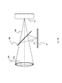
ライトフィールドデータ取得デバイス1000の構成を図1に示す。被写体101の画像を形成するレンズ部102及び撮像素子104は、光軸120に沿って配置される。デバイス1000において、レンズ部は、例えばオートフォーカス機能及びズーム機能用の複数のレンズを含みうる。レンズ部102は、省略するために図1では1つのレンズとして描かれる。
The configuration of the light field
符号102aはレンズ部の瞳を示す。瞳は、レンズ部102の開口絞りの画像である。技術的に、瞳102aを射出瞳と呼んでもよい。レンズ部102は、デバイス1000のレンズ部の分解能及び画角に関連する。
ビームスプリッタ103(例えば、ダイクロイックビームスプリッタ、50:50ビームスプリッタ、80:20ビームスプリッタ、90:10ビームスプリッタ及び偏光ビームスプリッタ)は、図1に示されるように、放射線121(例えば、近赤外線、赤外線、紫外線、可視光)を光117から分離しうる。ビームスプリッタ103を通過する光150は撮像素子104により検出可能であり、分離(反射、偏向)された放射線121は、図1において小型レンズアレイ107に入射しうる。ビームスプリッタ103は、光117を撮像素子に対する可視光と、小型レンズアレイ107及び検出部を含むライトフィールドセンサ160に対する近赤外光とに分割してもよい。検出部は、空間光変調器(以下、SLM)108と、検出器109とを備えうる。SLM108及び検出器109(光検出器等)を使用するのではなく、撮像素子アレイ(例えば、CCDアレイ、CMOSアレイ)が使用されてもよい。
Beam splitter 103 (e.g., dichroic beam splitter, 50:50 beam splitter, 80:20 beam splitter, 90:10 beam splitter, and polarizing beam splitter) is configured with radiation 121 (e.g., near infrared, Infrared, ultraviolet, visible light) can be separated from the
例えばビームスプリッタ103は、被写体101からの光を撮像素子104により検出される光117の80%の可視光と、検出部160により検出される光117の20%の可視光とに分割してもよい。そのようなビームスプリッタを上記のように「80:20ビームスプリッタ」として説明する。
For example, the
分離された放射線121は、SLM108及び検出部である検出器109(例えば、光検出器)を使用することで検出されうる。SLM108は複数の画素グループを有する。各画素グループは、検出器109を使用することにより、小型レンズアレイ107の各小型レンズと関連付けられて、被写体101のライトフィールドデータに関する情報を取得してもよい。SLM108の全ての画素グループは個々に駆動されうる。例えばSLMは、LCD(液晶デバイス)又はDMD(デジタルマイクロミラーデバイス)であってもよい。
The
ライトフィールドセンサ160は、小型レンズアレイ107及び撮像素子アレイ等の検出部又はSLM108と光検出器109との組合せを含んでもよい。例えば、以下の構成が使用可能である。(a)撮像素子104が可視光を検出し、ライトフィールドセンサ160が可視光を更に検出する。(b)撮像素子104が可視光を検出し、ライトフィールドセンサ160が、近赤外線及び/又は赤外線、並びに/あるいは紫外光を検出する。
The
図2A及び図2Bに示されるように、分離された放射線121は、ライトフィールドセンサ160だけではなく、撮像素子104によっても検出されうる。以下において、図1を用いて図2Aのシステム構成を例示的に説明し、可視光は、撮像素子104により検出される光の一例として使用され、近赤外光は、分離された光121の一例として使用される。
As shown in FIGS. 2A and 2B, the
ビームスプリッタ103を通過する可視光(150)は、像面上にある撮像素子104により検出されうる。ビームスプリッタ103により反射される近赤外線(121)は、小型レンズアレイ107に入射可能であり、小型レンズアレイ107からの光は、SLM108を介して検出器109により検出可能である。本発明の実施形態において、可視光は、撮像素子104を使用することで像面上に蓄積する光の量を取り込むために使用され、近赤外線121は、レンズ部102の瞳102aに到達する被写体101からの光の方向に関する情報を取得するために使用される。
Visible light (150) passing through the
可視光(150)の画像105及び近赤外線(121)の画像106が形成され、それぞれ撮像素子104及び小型レンズアレイ107に合焦される。ビームスプリッタ103と小型レンズアレイ107との間の長さは、ビームスプリッタ103と撮像素子104との間の長さと同一であってもよい。各要素(例えば、小型レンズアレイ107、SLM108及び光センサ109)は、それぞれ縮小して図1に示される。SLM108の位置は、レンズ部102の瞳102aの位置と共役であるように設定される。瞳102aにおける画像は、図1に示されるようにSLM108上に形成される。図中符号102bは、SLM108上に形成された瞳102aに対応する画像を示す。SLM108上に瞳102aの画像を形成するために、小型レンズアレイ107及びレンズ部102の出口側に配置されたレンズから構成されうる有効レンズの倍率及び有効位置は、近軸理論により求められうる。SLM108は有効位置に配置されうる。瞳102aが形成される瞳面は、SLM108又は検出部と共役でありうる。上記の共役関係ではなく、SLM108の位置は、レンズ部102の1つの主レンズの位置と共役であるように設定されてもよく、主レンズにおける光の方向に関する情報が取得されてもよい。
An
レンズ部102の瞳面がズーム動作に従って光軸120に沿ってシフトしている間、画像105は、被写体101と画像105との光学共役関係を維持することで撮像素子104上に連続して形成されうる。形成された画像105に関する情報は撮像素子104により検出可能であり、検出された情報はメモリに格納されうる。
While the pupil plane of the
ビームスプリッタ103により反射された近赤外線(121)は、小型レンズアレイ107及びSLM108を介して検出器109(例えば、光検出器)により検出されうる。
The near-infrared ray (121) reflected by the
レンズ部102の瞳102a上の近赤外線(121)は、SLM108と共役されるように設計され、且つ小型レンズアレイ107上に画像を形成する。検出器109は、SLM108を介して小型レンズアレイ107上に画像を形成する光により照射されうる。SLM108上の照射の状態は、小型レンズアレイ107の小型レンズからの光束の角度に対応し、小型レンズからの光束の角度は、小型レンズに入射する分離された近赤外線121の角度に対応する。
Near infrared light (121) on the
小型レンズからの出力角度は、小型レンズへの入射角度に依存しうる。分離された放射線121の入射角度は、瞳102a上の被写体101からの光の位置及び方向に依存しうる。光の角度等のライトフィールドデータは、検出部により検出され且つ被写体の深度情報と関連付けられうる。瞳102a上の光の位置及び方向は、被写体101の点の位置、すなわち被写体101の深度情報に依存する。
The output angle from the lenslet can depend on the angle of incidence on the lenslet. The incident angle of the separated
検出器109上の照射位置は入射光121の角度及び出力角度に依存するため、照射位置及びその照射量に関する情報を取得することは、レンズ部102の瞳102a上の近赤外線の位置及び角度(方向)を認識することを意味する。従って、瞳102a上の光束の角度は、SLM108の画素と関連付けられうる。角度毎の光の強度は、光検出器109により検出されうる。
Since the irradiation position on the
光検出器109は、フォトダイオード及び光電子増倍管から選択されうる。フォトダイオードは、可視光、紫外光、赤外光又は近赤外光に対するものであってよい。特定の主レンズ及び特定の小型レンズアレイ108を図1に示すが、現在入手可能であるかあるいは将来開発されるであろう種々のレンズ及び/又は小型レンズアレイは、例えば、開示されたレンズ部及び/又は小型レンズアレイを置換することにより、同様の方法で実現されうることが当業者により理解されるだろう。レンズ部102に加え、他の機能レンズ部が本実施形態に追加されてよい。
The
SLM108は複数の画素を含み、各画素は、開口である開状態及びシャッターである閉状態でありうる。1つの小型レンズは、m*m画素(例えば、5×5画素)と関連付けられうる。各小型レンズがピンホールカメラであると考えられうるため、小型レンズに入射する光束の方向は、m*m画素のうちのどの画素が照射されるかに関する情報により認識されうる。小型レンズアレイ107に入射する光束の角度分布は、SLM108の開口を走査(変更)することで実行されうる。
The
図1において、被写体101からの光の角度は、小型レンズアレイ107及びSLM108を介して検出器109により検出されるが、小型レンズ及びSLM108の位置の順序を変更できてもよい。図1において、小型レンズアレイ107はSLM108で置換されてもよく、SLM108は小型レンズアレイ107で置換されてもよい。
In FIG. 1, the angle of the light from the subject 101 is detected by the
瞳102aは、レンズ部102の内部に描かれるが、レンズ部102の外側に配置されてもよい。レンズ部102のズーム動作に従って瞳102aの位置が移動しうるが、検出器109を含むSLM108は、瞳102aの位置とSLM108の位置との共役関係を維持するために主レンズ102の瞳の移動に従って移動されうる。SLM108及び光検出器109を備えてもよい検出部と瞳102aとの共役関係が維持されるように、SLMは、ズーム動作に従ってアクチュエータ116により移動されうる。瞳102aとSLM108との共役関係は維持されうる。
The
SLM108を移動させるために、アクチュエータ116(例えば、ステッピングモータ、微小電気機械システム(MEMS)、ボイスコイルモータ、超音波モータ、圧電モータ)が提供されうる。瞳をシフトさせるズーム動作に従って、SLM108上に形成された瞳の画像はシフトされうる。画像のシフトに従うために、SLM107は、ある特定の量だけアクチュエータ116によりシフトされうる。空間光変調器108は、ズーム動作と同期されるようにアクチュエータ116により移動されうる。
In order to move the
瞳面のシフト量に対応するルックアップテーブルは、SLM108のシフト量を算出するために使用されてもよい。SLM108が実質的に検出器109と組み合わされる場合、検出器109は、SLM108のシフトともしてもシフトされうる。
A lookup table corresponding to the shift amount of the pupil plane may be used to calculate the shift amount of the
ビームスプリッタ103と、撮像素子104と、ライトフィールドセンサ160とを備えてもよいカメラ本体及びレンズ部102は互いに分離されてもよく、制御器は、CPU及びメモリを含むカメラ本体にあってもよい。カメラ本体は、レンズ部がカメラ本体に接続されることを検出し、且つどのレンズ部が接続されるかを見つけうる。メモリがルックアップテーブルを格納する場合、制御器は、ルックアップテーブルに基づいてSLM108の特定のシフト量を提供しうる。
The camera main body and the
レンズ部102の瞳102aがズーム動作に従って範囲110を移動する場合、検出器109を有するSLM108は、瞳102の位置とSLM108の位置との共役関係を維持するために、範囲111内のアクチュエータ116により瞳の移動と同期されうる。
When the
本実施形態において、空間情報を取得するシステムは、角度情報を取得するシステムの影響を受けない。影響を受けないため、瞳102aの位置が変化したとしても、瞳とSLM108との共役関係を維持できる。
In the present embodiment, the system that acquires the spatial information is not affected by the system that acquires the angle information. Since it is not affected, even if the position of the
高空間分解能及び高角度分解能の双方を得るのは困難であると言われている。しかし、光が2つの光束に分割されるため、先に開示された撮像装置は、高空間分解能及び高角度分解能の双方を提供しうる。一方は空間情報を検出するために使用され、他方は角度情報を検出するために使用される。 It is said that it is difficult to obtain both high spatial resolution and high angular resolution. However, since the light is split into two light fluxes, the previously disclosed imaging device can provide both high spatial resolution and high angular resolution. One is used to detect spatial information and the other is used to detect angle information.
ライトフィールドセンサの各点(x,y)に到達し且つレンズ部の平面の各点(u,v)からの全ての光線を統合することにより、ライトフィールドデータ(例えば、f(u,v,x,y))から写真画像を取得できることが知られている。 By integrating all rays from each point (u, v) of the plane of the lens unit, reaching each point (x, y) of the light field sensor, light field data (e.g., f (u, v, It is known that photographic images can be obtained from x, y)).
以下において、ライトフィールドデータを取得する処理を詳細に説明する。 In the following, a process for acquiring light field data will be described in detail.
図3において、光は、レンズ部102及びビームスプリッタ103を介して小型レンズアレイ107に到達する。被写体101の画像は、レンズ部102により撮像素子104上に形成される。2種類の光束(すなわち、軸上光束117及び軸外光束118)について図3で説明する。軸上光束117は被写体101の下端に対応しており、軸外光束118は被写体101の上端に対応している。
In FIG. 3, the light reaches the
複数の可視光束は、撮像素子104の各画素上に被写体画像を形成する。一方、近赤外線は小型レンズアレイ107に入射する。近赤外線(121、123)は、瞳102a上の光束の複数の角度成分から構成され、小型レンズアレイ107により分離された後に各角度成分に従ってSLM108に入射する。
The plurality of visible light beams form a subject image on each pixel of the
図3において、被写体101からの軸上光117の一部は、ビームスプリッタ103により偏向(すなわち、反射)され、瞳102aにおける光の角度に従う種々の角度で小型レンズアレイ107に入射される。
In FIG. 3, a part of the on-
軸上光117の偏向光束121は検出器109により検出され、検出された信号は瞳102aにおける光の角度(方向)に依存しうる。SLM108の開口を走査することにより、瞳102aの各角度における光強度がサンプリングされうる。瞳102aにおける光の角度がSLM108の画素と関連付けられうるため、角度情報は光強度分布を使用して取得されうる。
The deflected
一方、被写体101の位置155からの軸外光118は、レンズ部102に進み、ビームスプリッタ103により偏向される。軸外光118の偏向光123は、軸上光118が到達する位置における角度とは異なる角度を有する位置において検出器109にも到達しうる。
On the other hand, off-
撮像素子104上の被写体101の画像105の高さ(長さ)又は位置は、被写体101の実際の高さに依存しうる。軸上可視光117は位置119において素子104に進み、且つ軸外可視光118は素子104上の位置129に進みうる。
The height (length) or position of the
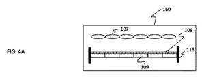
上述したように、ズーム動作中に瞳102aの位置とSLM108の位置との共役関係を維持するために、アクチュエータ116は、主レンズ102の瞳面の移動に従って検出器109を有するSLM108を移動させるために使用されうる。図4A及び図4Bに示されるように、SLM108を有する検出器109を移動させるためのアクチュエータ116は、ライトフィールドセンサ160において提供されて、撮像素子アレイ109bを移動させうる。
As described above, in order to maintain the conjugate relationship between the position of the
瞳の位置が軸外角度に依存してもよいため、瞳面は平面でなくてもよい。その場合、小型レンズアレイは、瞳面の形状に従って曲げられてもよい。小型レンズアレイ107の各小型レンズの倍率は、瞳面の形状に従って変動しうる。各小型レンズの倍率は、各小型レンズの光学倍率である。
Since the pupil position may depend on the off-axis angle, the pupil plane may not be a plane. In that case, the lenslet array may be bent according to the shape of the pupil plane. The magnification of each small lens of the
レンズ部102から発せられた光束(124a、124b及び124c)とSLM108を含む検出器109上の集光との関係を図5に示す。複数の光束(124a、124b及び124c)は、瞳102aの位置126において互いに異なる角度を有しうる。照射光125a及び125bは、SLM108の各画素を介して検出器109に入射されうる。
FIG. 5 shows the relationship between the light beams (124a, 124b and 124c) emitted from the
検出器109上の照射位置は、瞳面102からの光束(124a、124b及び124c)の角度に依存する。小型レンズアレイ107における各小型レンズへの入射角度は、被写体101の高さにも依存してもよい。従って、検出器109上の照射光の位置を測定することにより、被写体の高さの関数である光の角度に関する情報を取得できる。
The irradiation position on the
図6に示されるように、近赤外線112a、112b及び112cは、小型レンズアレイ107を介して検出器109に入射されうる。プログラム可能なSLM108a(108b)の断面図501及び上面図502を示す。SLM108の上面図502において、照射スポット113a、113b及び113cを説明する。照射スポットの位置及びプロファイルに関する情報を使用することにより、瞳面における照射光に対応している各小型レンズに入射する光の角度が得られる。
As shown in FIG. 6, the near
従来のプレノプティックカメラは、撮像素子の前にマイクロレンズアレイを有する。1つのマイクロレンズが撮像素子の5×5画素に対応している場合、角度情報は、5×5画素を使用することで検出されうる。5×5画素の画像が空間情報の1つの単位であると考えられるため、画像解像度は低下しうる。しかし、上述の本発明の実施形態及び画像解像度を維持できる。 A conventional plenoptic camera has a microlens array in front of an image sensor. If one microlens corresponds to 5 × 5 pixels of the image sensor, the angle information can be detected by using 5 × 5 pixels. Since a 5 × 5 pixel image is considered to be one unit of spatial information, the image resolution can be reduced. However, the above-described embodiments of the present invention and image resolution can be maintained.
図7において、上部の図501は、撮像素子104の画素の一部を説明し、図中符号114−(m,1)は、小型レンズの座標(m,1)に対応する撮像素子104における5×5画素のブロックを示す。
In FIG. 7, the
下部の図502は、SLM108の画素の一部を説明する。符号113a、113b及び113cは、SLM108上の照射スポットを示す。集束スポットに関する情報に基づいて、角度情報が算出されうる。1つの角度は、5×5画素を使用することで取得されてもよいが、1つの空間データ(すなわち、画像情報)は、1つの画素を使用して検出されうる。
The lower diagram 502 illustrates some of the pixels of the
図1に示されるような構成を使用することにより、撮像素子104及び小型レンズアレイ107は、被写体101に対する同一の光共役位置に配置されうる。撮像素子104上の画像のサイズが小型レンズアレイ上の画像のサイズと同一である場合、小型レンズアレイ上の画像は、各画素における撮像素子104上の画像と関連付けられうる。
By using the configuration as shown in FIG. 1, the
多数の画素、例えば1M個を超える画素を有するデジタルカメラの場合、特定の5×5画素ブロックにより範囲に含まれた画像フィールドは非常に制限されるため、通常、5×5画素ブロックにおいて1つの被写体しか観察できない。このような状況において、先の特定の5×5画素ブロックへの光束の角度が規定され、1つの角度データは5×5画素に割り当てられうる。角度データは、5×5画素ブロックの画素毎に同一である。本発明の第1の実施形態において、個々の小型レンズと撮像素子104の画素との間には1対1の関係がある。本発明の第2の実施形態において、個々の小型レンズは、撮像素子104の複数の画素と関連付けられる。本発明の第3の実施形態において、複数の小型レンズは、撮像素子104の個々の画素と関連付けられる。
For digital cameras with a large number of pixels, for example more than 1M pixels, the image field covered by a particular 5 × 5 pixel block is very limited, so usually one in a 5 × 5 pixel block Only the subject can be observed. In such a situation, the angle of the light beam to the specific 5 × 5 pixel block is defined, and one angle data can be assigned to 5 × 5 pixels. The angle data is the same for each pixel of the 5 × 5 pixel block. In the first embodiment of the present invention, there is a one-to-one relationship between each small lens and the pixel of the
角度分解能は、SLMの画素数及び小型レンズの画素数に依存しうる。 The angular resolution may depend on the number of pixels of the SLM and the number of pixels of the small lens.
小型レンズ及びSLMは最適化されうる。人間の眼の角度分解能が相対的に空間分解能よりかなり低いため、上述したように空間データ及び角度データが別個に測定される場合でも、角度データの平均値は、特定の5×5画素に対する角度データとして使用されうる。 The lenslet and SLM can be optimized. Since the angular resolution of the human eye is relatively lower than the spatial resolution, even if the spatial data and the angular data are measured separately as described above, the average value of the angular data is the angle for a specific 5 × 5 pixel. Can be used as data.
座標データ(すなわち、空間情報)と角度データとの相関性を以下において説明する。 The correlation between coordinate data (that is, spatial information) and angle data will be described below.
移動体を撮像する場合、角度データは座標データより影響されやすい。特定の時間、例えば1/60秒の間の座標情報の信号は、メモリに蓄積されうる。 When imaging a moving body, angle data is more susceptible than coordinate data. A signal of coordinate information for a specific time, eg 1/60 second, can be stored in the memory.
一方、移動体の縁部における深度データは、1/60秒等の上記の蓄積時間にわたり急速に変化しうる。従って、角度データの精度は、種々雑多な角度データのためにそのような蓄積時間にわたり低下しうる。これは、被写体の移動に対応する角度データの変化速度が座標情報の変化速度より高速でありうることを意味する。 On the other hand, the depth data at the edge of the mobile can change rapidly over the above accumulation time, such as 1/60 second. Accordingly, the accuracy of the angle data can be reduced over such an accumulation time due to various miscellaneous angle data. This means that the change speed of the angle data corresponding to the movement of the subject can be faster than the change speed of the coordinate information.
角度データは、座標データの取得期間より短い期間の間に取得されるべきである。SLMは、撮像素子の代わりにより高速にサンプリングできる。SLMは、広範な光学帯域幅、室温安定性及び高速性能に対する潜在性を考慮して、LCD(液晶デバイス)、DMD(デジタルマイクロミラーデバイス)及びEO(電気光学)ポリマを用いたSLM等から選択されうる。 The angle data should be acquired during a period shorter than the acquisition period of the coordinate data. The SLM can sample at a higher speed instead of the image sensor. SLM is selected from LCD (Liquid Crystal Device), DMD (Digital Micromirror Device), SLM using EO (electro-optic) polymer, etc. considering wide optical bandwidth, room temperature stability and potential for high speed performance Can be done.
角度データは、以下の方法で座標データと統合可能である。小型レンズ座標(1,1)のブロックの角度データa11は、所定の期間の間xij(i=1〜5、j=1〜5)の座標データに対して使用されうる。 The angle data can be integrated with the coordinate data by the following method. Angle data a 11 block lenslet coordinates (1,1) for a predetermined period of time x ij (i = 1~5, j = 1~5) can be used for the coordinate data.
角度データのサンプリングが座標データのサンプリングより高速でありうるため、角度データは補間座標データに対応しうる。 Since the sampling of angle data can be faster than the sampling of coordinate data, the angle data can correspond to interpolated coordinate data.
t1、t2、及びt3における撮像素子104の5×5画素に対する画像データ(128a、128b及び128c)を図8Aに示す。画像データは可視光に基づきうる。水平軸は時間を示す。
FIG. 8A shows image data (128a, 128b, and 128c) for 5 × 5 pixels of the
図8Bの図中符号127は、撮像素子104の5×5画素の面積に対応する特定の小型レンズと関連付けられてもよい検出器109から出力された信号である。検出器109からの信号127は連続して検出可能であり、t0とt1との間の結果のうちの1つは、t1における角度データとして設定されうる。角度データは、撮像素子104によりt1において検出された画像データと関連付けられうる。t1における画像データは、t0とt1との間で統合されたデータでありうる。t0とt1との間の周期は、例えば1/60秒である。
8B is a signal output from the
図8Cにおいて、特定の小型レンズに対応するSLMの5×5画素を示し、符号129a〜129gは、特定の小型レンズからの光により照射されるスポット部分である。信号強度は、図8Bの信号127により検出されうる。
In FIG. 8C, 5 × 5 pixels of the SLM corresponding to a specific small lens are shown, and
小型レンズアレイ107の各小型レンズは、SLMの5×5画素の各々と関連付けられ、且つSLMの5×5画素の各々は個々に駆動されうる。スポット部分に関する情報(すなわち、位置及びプロファイル)に基づいて、小型レンズに入射される光の角度情報(130a〜130g)は、図8Dに示されるように取得されうる。瞳102a上の光の方向が角度情報に対応しているため、最終的に、画像データ(128a、128b、128c)は、図8Eの131a、131b及び131cにおいて説明されるような角度情報(すなわち、深度情報)と関連付けられうる。
Each lenslet of the
複数の角度データは、1つのフレーム(t0〜t1、t1〜t2及びt2〜t3)において検出されうるが、それらの1つの角度データは、1つのフレームに割り当てられうる。1つのフレームの間の角度情報の平均値は、1つのフレームに割り当てられてもよい。 A plurality of angle data can be detected in one frame (t 0 to t 1 , t 1 to t 2 and t 2 to t 3 ), but the one angle data can be assigned to one frame. An average value of angle information between one frame may be assigned to one frame.
上述したように、撮像素子104は、所定の時間フレームにおいて被写体101の画像105を撮像でき、光検出器は、偏向光121を検出して所定の時間フレームの間に複数の角度データを取得できる。複数の角度データのうちの1つの角度データは、全ての所定の時間フレームの間に撮像素子104により形成された被写体101の1つの画像と関連付けられうる。
As described above, the
換言すると、光検出器109のサンプリング周波数は、撮像素子104のサンプリング周波数と異なってもよい。例えば、空間光センサのサンプリング周波数は、撮像素子のサンプリング周波数より高くてもよい。図8Bの信号127を監視することにより、撮像されるシーンの変化を検出してもよい。
In other words, the sampling frequency of the
角度データがフレーム期間中に急速に変化する場合、各フレーム期間における適切な角度データが要求されうる。フレーム期間中の角度データの最大値は、適切な角度データとして選択されうる。本発明の別の一実施形態において、フレーム期間中の角度データの平均値は、適切な角度データとして選択されうる。代表的な角度データを選択するために、他の統計方法が使用されてもよい。角度データは、高次統計計測値を使用して更に表されてもよい。 If the angle data changes rapidly during a frame period, appropriate angle data for each frame period may be required. The maximum value of the angle data during the frame period can be selected as appropriate angle data. In another embodiment of the present invention, an average value of angle data during a frame period may be selected as appropriate angle data. Other statistical methods may be used to select representative angle data. The angle data may be further represented using higher order statistical measurements.
図9において、画像処理方法の一例を説明する。ステップS1において、主レンズ102を通過した被写体101からの被写体光は、可視光、並びにIR(赤外線)光及び/又はUV光に分割される。ステップS2において、空間データ(画像データ)は、撮像素子104により検出されうる。空間データは、1つのフレーム期間(例えば、1/60秒)の間に全ての画素に対して読み出される。
An example of the image processing method will be described with reference to FIG. In step S1, subject light from the subject 101 that has passed through the
ステップS3において、IR光及び/又はUV光は、小型レンズアレイ107に入射される。ステップS4において、各小型レンズはSLM108の画素と関連付けられ、光検出器109を照射するためにSLMが走査される。SLMのサンプリングレートは、撮像素子104のフレームレートより高速でありうる。走査結果に基づいて、SLMの画素のIR光及び/又はUV光により照射されるスポットに関する情報は、ステップS5で取得される。情報は、IR光及び/又はUV光の角度データを与えうる。1つのフレーム内にいくつかの角度データがある場合、1つのフレームの間の代表的なデータ値は、ステップS6で選択されうる。空間データは、ステップS7で角度データを組み合わされうる。ステップS8において、例えば、ユーザからの命令に基づいて画像が再構成されうる。
In step S <b> 3, IR light and / or UV light is incident on the
ステップS4において、光検出器からの信号が連続して出力されうるため。出力信号が特定の閾値内でほぼ同一のレベルである場合、光検出器の集束位置(スポット)及び強度プロファイルは決して変化しないと仮定できる。その場合、SLMの走査は、信号強度の変化が閾値を超えるまで省略されてもよい。出力信号が変化した場合、走査ステップが再度実行されうる。 In step S4, the signal from the photodetector can be output continuously. If the output signal is at approximately the same level within a certain threshold, it can be assumed that the focus position (spot) and intensity profile of the photodetector will never change. In that case, scanning of the SLM may be omitted until the change in signal intensity exceeds a threshold value. If the output signal changes, the scanning step can be performed again.
図10Aにおいて、小型レンズアレイ107の各小型レンズは、SLM108を介して別の小型レンズアレイ207の別の小型レンズと関連付けられてもよく、小型レンズ207からの光は、光検出器(109a、109b、109c、109d及び109e)により検出されうる。図1のビームスプリッタ103により選択される光は、小型レンズ114を介して検出器109a、109b及び109cにそれぞれ入射される。SLM108と光検出器との間の小型レンズアレイ207を使用することにより、光検出器のサイズを小型化できる。
In FIG. 10A, each lenslet of the
図10Bにおいて、角度情報を感知する撮像素子209(例えば、CMOSアレイ、CCDアレイ及び撮像管)は、図1の検出器109(例えば、フォトダイオード)の代わりに小型レンズアレイ107の下に提供される。瞳における角度分解能を向上させるために、SLM108の各画素が縮小される必要があるだろう。SLMの画素の縮小サイズに対して、そのような撮像素子209は、角度情報を検出するのに有用だろう。
In FIG. 10B, an image sensor 209 (eg, CMOS array, CCD array, and image tube) that senses angle information is provided under the
計算してライトフィールドセンサ160の検出結果に基づいて角度データを取得するために、ゼルニケ多項式が使用されてもよい。
A Zernike polynomial may be used to calculate and obtain angle data based on the detection result of the
2011年5月3日に発行されたNg他に対する米国特許第7,936,392号公報、2010年6月10日に公開されたKnight他に対する米国特許出願公開第2010/0141802号明細書、2010年2月4日に公開されたNg他に対する米国特許出願公開第2010/0026852号明細書、2011年6月21日に発行されたRaskar他に対する米国特許第7,965,936号公報、2012年7月24日に発行されたAgrawal他に対する米国特許第8,229,294号公報、2011年2月10日に公開されたRamos他に対する米国特許出願公開第2011/0032337号明細書、2006年10月10日に発行されたSeoに対する米国特許第7,119,842号公報及び2011年6月2日に公開されたMilines他に対する米国特許出願公開第2011/0128412号明細書に記載された内容は、それらの全ての内容が本明細書において開示されているものとして、本明細書の開示内容として組み込まれる。 US Pat. No. 7,936,392 to Ng et al. Issued May 3, 2011, US Patent Application Publication No. 2010/0141802 to Knight et al. Published June 10, 2010, 2010 U.S. Patent Application Publication No. 2010/0026852 to Ng et al. Published February 4, 2011, U.S. Patent No. 7,965,936 to Raskar et al. Issued June 21, 2011, 2012 U.S. Pat. No. 8,229,294 to Agrawal et al. Issued July 24, U.S. Patent Application Publication No. 2011/0032337 to Ramos et al. U.S. Pat. No. 7,119,842 to Seo issued on May 10 and June 2011 The contents described in US Patent Application Publication No. 2011/0128412 to Milines et al., Published on the 2nd, are incorporated herein by reference in their entirety. Incorporated as.
例示的な実施形態を参照して本発明に係る実施形態を説明したが、本発明は上述の実施形態に限定されないことが理解されるべきである。以下の特許請求の範囲の範囲は、そのような変更、並びに等価の構造及び機能の全てを含むように広範に解釈されるべきである。 Although embodiments according to the present invention have been described with reference to exemplary embodiments, it should be understood that the present invention is not limited to the above-described embodiments. The scope of the following claims should be construed broadly to include all such modifications and equivalent structures and functions.
Claims (23)
当該装置に接続されるレンズ部を通過した被写体からの光を第1の光束及び第2の光束に分割するように構成されたビームスプリッタと、
前記第1の光束を検出して前記被写体の画像を形成するように構成された撮像素子と、
複数の小型レンズを含む小型レンズアレイ及び前記小型レンズアレイを通過した前記第2の光束を検出する検出部を含み、前記ライトフィールドデータに関する情報を取得するように構成されたライトフィールドセンサと、
アクチュエータとを備え、
前記検出部が設けられる第1の位置は、前記レンズ部の瞳の第2の位置と共役であり、
前記アクチュエータは、前記レンズ部の前記瞳が前記レンズ部のズーム動作に従って移動される場合に、前記第1の位置と前記第2の位置との共役関係を維持するために前記検出部を移動させることを特徴とする装置。 A device for obtaining information about light field data,
A beam splitter configured to split light from a subject that has passed through a lens unit connected to the apparatus into a first light beam and a second light beam;
An imaging device configured to detect the first light flux to form an image of the subject;
A light field sensor that includes a small lens array including a plurality of small lenses and a detection unit that detects the second light flux that has passed through the small lens array, and is configured to acquire information on the light field data;
An actuator ,
A first position where the detecting unit is provided, Ri second position conjugate with Der pupil of the lens portion,
The actuator moves the detection unit to maintain a conjugate relationship between the first position and the second position when the pupil of the lens unit is moved according to a zoom operation of the lens unit. A device characterized by that.
レンズ部と、
被写体からの光を第1の光束及び第2の光束に分割するように構成されたビームスプリッタと、
前記第1の光束を検出して前記被写体の画像を形成するように構成された撮像素子と、
複数の小型レンズを含む小型レンズアレイ及び前記小型レンズアレイを通過した前記第2の光束を検出する検出部を含み、前記ライトフィールドデータに関する情報を取得するように構成されたライトフィールドセンサと、
アクチュエータとを備え、
前記検出部が設けられる第1の位置は、前記レンズ部の瞳の第2の位置と共役であり、
前記アクチュエータは、前記レンズ部の前記瞳が前記レンズ部のズーム動作に従って移動される場合に、前記第1の位置と前記第2の位置との共役関係を維持するために前記検出部を移動させることを特徴とする装置。 A device for obtaining information about light field data,
The lens part,
A beam splitter configured to split light from the subject into a first light flux and a second light flux;
An imaging device configured to detect the first light flux to form an image of the subject;
A light field sensor that includes a small lens array including a plurality of small lenses and a detection unit that detects the second light flux that has passed through the small lens array, and is configured to acquire information on the light field data;
An actuator ,
A first position where the detecting unit is provided, Ri second position conjugate with Der pupil of the lens portion,
The actuator moves the detection unit to maintain a conjugate relationship between the first position and the second position when the pupil of the lens unit is moved according to a zoom operation of the lens unit. A device characterized by that.
レンズ部を通過する被写体の光を第1の光束及び第2の光束に分割することと、
前記被写体の画像を撮像するために前記第1の光束を検出することと、
前記第2の光束を、複数の小型レンズを含む小型レンズアレイ及び前記小型レンズアレイを通過した前記第2の光束を検出する検出部を備えるライトフィールドセンサに入射させることと、
前記レンズ部の瞳が前記レンズ部のズーム動作に従って移動される場合に、前記レンズ部の前記瞳の位置と前記検出部の位置との共役関係が維持されるように前記レンズ部のズーム動作に従って前記検出部を移動させることと、を含む
ことを特徴とする方法。 A method for obtaining information about light field data,
Splitting the light of the subject passing through the lens unit into a first light flux and a second light flux;
Detecting the first light flux to capture an image of the subject;
Causing the second light beam to enter a light field sensor including a small lens array including a plurality of small lenses and a detection unit that detects the second light beam that has passed through the small lens array ;
When the pupil of the lens unit is moved according to the zoom operation of the lens unit, the conjugate operation between the position of the pupil of the lens unit and the position of the detection unit is maintained according to the zoom operation of the lens unit. Moving the detection unit . A method comprising:
Applications Claiming Priority (3)
| Application Number | Priority Date | Filing Date | Title |
|---|---|---|---|
| US13/603,294 US9036080B2 (en) | 2012-09-04 | 2012-09-04 | Apparatus and method for acquiring information about light-field data |
| US13/603,294 | 2012-09-04 | ||
| PCT/US2013/056813 WO2014039327A1 (en) | 2012-09-04 | 2013-08-27 | Apparatus and method for acquiring information about light-field data |
Publications (3)
| Publication Number | Publication Date |
|---|---|
| JP2015537397A JP2015537397A (en) | 2015-12-24 |
| JP2015537397A5 JP2015537397A5 (en) | 2016-10-13 |
| JP6320385B2 true JP6320385B2 (en) | 2018-05-09 |
Family
ID=50187084
Family Applications (1)
| Application Number | Title | Priority Date | Filing Date |
|---|---|---|---|
| JP2015529932A Active JP6320385B2 (en) | 2012-09-04 | 2013-08-27 | Apparatus and method for acquiring information on light field data |
Country Status (3)
| Country | Link |
|---|---|
| US (1) | US9036080B2 (en) |
| JP (1) | JP6320385B2 (en) |
| WO (1) | WO2014039327A1 (en) |
Families Citing this family (41)
| Publication number | Priority date | Publication date | Assignee | Title |
|---|---|---|---|---|
| ES2463390T3 (en) * | 2011-06-24 | 2014-05-27 | Tomra Systems Asa | Reverse vending machine and representation method using images for it |
| CN108334204B (en) | 2012-12-10 | 2021-07-30 | 因维萨热技术公司 | Image forming apparatus with a plurality of image forming units |
| US9497380B1 (en) | 2013-02-15 | 2016-11-15 | Red.Com, Inc. | Dense field imaging |
| US9706116B2 (en) * | 2013-10-31 | 2017-07-11 | Ricoh Co., Ltd. | Plenoptic color imaging system with enhanced resolution |
| JP2015230989A (en) * | 2014-06-05 | 2015-12-21 | 株式会社リコー | Imaging module and imaging device |
| WO2015188146A2 (en) * | 2014-06-05 | 2015-12-10 | Edward Hartley Sargent | Sensors and systems for the capture of scenes and events in space and time |
| TWI491856B (en) * | 2014-06-20 | 2015-07-11 | Univ Nat Central | Detecting system |
| US9692968B2 (en) | 2014-07-31 | 2017-06-27 | Invisage Technologies, Inc. | Multi-mode power-efficient light and gesture sensing in image sensors |
| EP3001672A1 (en) * | 2014-09-25 | 2016-03-30 | Thomson Licensing | Plenoptic camera comprising a spatial light modulator |
| DE102014115292A1 (en) * | 2014-10-21 | 2016-04-21 | Connaught Electronics Ltd. | Method for providing image files from a camera system, camera system and motor vehicle |
| DE102014115294A1 (en) * | 2014-10-21 | 2016-04-21 | Connaught Electronics Ltd. | Camera system for a motor vehicle, driver assistance system, motor vehicle and method for merging image data |
| US10511787B2 (en) * | 2015-02-12 | 2019-12-17 | Fraunhofer-Gesellschaft Zur Foerderung Der Angewandten Forschung E.V. | Light-field camera |
| US9918024B2 (en) * | 2015-05-22 | 2018-03-13 | Google Llc | Multi functional camera with beam splitter |
| CA2901477C (en) | 2015-08-25 | 2023-07-18 | Evolution Optiks Limited | Vision correction system, method and graphical user interface for implementation on electronic devices having a graphical display |
| CN105739091B (en) * | 2016-03-16 | 2018-10-12 | 中国人民解放军国防科学技术大学 | A kind of imaging method and device weakening atmospheric turbulance influence |
| EP3301647A1 (en) | 2016-09-30 | 2018-04-04 | Thomson Licensing | A method and an electronic device for calibrating a plenoptic camera |
| CN107920188A (en) * | 2016-10-08 | 2018-04-17 | 杭州海康威视数字技术股份有限公司 | A kind of camera lens and video camera |
| IL308136A (en) * | 2016-11-10 | 2023-12-01 | Magic Leap Inc | Method and system for multiple f-number lens |
| CN109642820B (en) * | 2017-12-22 | 2021-12-07 | 深圳配天智能技术研究院有限公司 | Optical sensing device, detection system and detection method |
| US11693239B2 (en) | 2018-03-09 | 2023-07-04 | Evolution Optiks Limited | Vision correction system and method, light field display and light field shaping layer and alignment therefor |
| CA3021636A1 (en) | 2018-10-22 | 2020-04-22 | Evolution Optiks Limited | Light field display, adjusted pixel rendering method therefor, and vision correction system and method using same |
| US11353699B2 (en) | 2018-03-09 | 2022-06-07 | Evolution Optiks Limited | Vision correction system and method, light field display and light field shaping layer and alignment therefor |
| JP7028983B2 (en) * | 2018-08-04 | 2022-03-02 | コアフォトニクス リミテッド | Switchable continuous display information system on the camera |
| US10936064B2 (en) | 2018-10-22 | 2021-03-02 | Evolution Optiks Limited | Light field display, adjusted pixel rendering method therefor, and adjusted vision perception system and method using same addressing astigmatism or similar conditions |
| US11287883B2 (en) | 2018-10-22 | 2022-03-29 | Evolution Optiks Limited | Light field device, pixel rendering method therefor, and adjusted vision perception system and method using same |
| US11500460B2 (en) | 2018-10-22 | 2022-11-15 | Evolution Optiks Limited | Light field device, optical aberration compensation or simulation rendering |
| US10761604B2 (en) | 2018-10-22 | 2020-09-01 | Evolution Optiks Limited | Light field vision testing device, adjusted pixel rendering method therefor, and vision testing system and method using same |
| US11327563B2 (en) | 2018-10-22 | 2022-05-10 | Evolution Optiks Limited | Light field vision-based testing device, adjusted pixel rendering method therefor, and online vision-based testing management system and method using same |
| US10636116B1 (en) | 2018-10-22 | 2020-04-28 | Evolution Optiks Limited | Light field display, adjusted pixel rendering method therefor, and vision correction system and method using same |
| US10860099B2 (en) | 2018-10-22 | 2020-12-08 | Evolution Optiks Limited | Light field display, adjusted pixel rendering method therefor, and adjusted vision perception system and method using same addressing astigmatism or similar conditions |
| US11789531B2 (en) | 2019-01-28 | 2023-10-17 | Evolution Optiks Limited | Light field vision-based testing device, system and method |
| US11500461B2 (en) | 2019-11-01 | 2022-11-15 | Evolution Optiks Limited | Light field vision-based testing device, system and method |
| US11635617B2 (en) | 2019-04-23 | 2023-04-25 | Evolution Optiks Limited | Digital display device comprising a complementary light field display or display portion, and vision correction system and method using same |
| US11777220B2 (en) | 2019-07-25 | 2023-10-03 | Syght, Inc. | Light path defining apparatus and methods |
| US11378829B2 (en) | 2019-07-25 | 2022-07-05 | Syght, Inc. | Advanced spatial light modulators, associated systems and methods |
| WO2021038422A2 (en) | 2019-08-26 | 2021-03-04 | Evolution Optiks Limited | Binocular light field display, adjusted pixel rendering method therefor, and vision correction system and method using same |
| CN110623625A (en) * | 2019-09-24 | 2019-12-31 | 东南大学苏州医疗器械研究院 | Three-dimensional imaging converter for two-dimensional laparoscope |
| CN110623626A (en) * | 2019-09-24 | 2019-12-31 | 东南大学苏州医疗器械研究院 | Two-dimensional-three-dimensional imaging converter for two-dimensional laparoscope |
| US11487361B1 (en) | 2019-11-01 | 2022-11-01 | Evolution Optiks Limited | Light field device and vision testing system using same |
| US11823598B2 (en) | 2019-11-01 | 2023-11-21 | Evolution Optiks Limited | Light field device, variable perception pixel rendering method therefor, and variable perception system and method using same |
| KR20230092477A (en) * | 2021-12-17 | 2023-06-26 | 삼성전자주식회사 | Spectroscopy device, apparatus and method for estimating bio-information |
Family Cites Families (21)
| Publication number | Priority date | Publication date | Assignee | Title |
|---|---|---|---|---|
| GB2282505A (en) * | 1993-09-23 | 1995-04-05 | Sharp Kk | Three dimensional imaging apparatus |
| JPH07261073A (en) * | 1994-03-23 | 1995-10-13 | Nikon Corp | Focusing position detecting device |
| JPH10197783A (en) * | 1996-12-27 | 1998-07-31 | Canon Inc | Focus detector |
| DE19822924C2 (en) | 1998-05-22 | 2000-06-15 | Daimler Chrysler Ag | Method and device for measuring the distribution of the energy field density of a laser beam |
| JP4931288B2 (en) | 2001-06-08 | 2012-05-16 | ペンタックスリコーイメージング株式会社 | Image detection device and diaphragm device |
| JP2004248018A (en) * | 2003-02-14 | 2004-09-02 | Konica Minolta Holdings Inc | Solid-state imaging unit and optical instrument provided with the same |
| WO2006039486A2 (en) | 2004-10-01 | 2006-04-13 | The Board Of Trustees Of The Leland Stanford Junior University | Imaging arrangements and methods therefor |
| US20060221209A1 (en) * | 2005-03-29 | 2006-10-05 | Mcguire Morgan | Apparatus and method for acquiring and combining images of a scene with multiple optical characteristics at multiple resolutions |
| US7680013B2 (en) | 2005-11-29 | 2010-03-16 | Canon Kabushiki Kaisha | Optical information recording and reproducing apparatus |
| US8248515B2 (en) | 2006-02-07 | 2012-08-21 | The Board Of Trustees Of The Leland Stanford Junior University | Variable imaging arrangements and methods therefor |
| US7792423B2 (en) | 2007-02-06 | 2010-09-07 | Mitsubishi Electric Research Laboratories, Inc. | 4D light field cameras |
| JP4992481B2 (en) * | 2007-03-09 | 2012-08-08 | 株式会社ニコン | Focus detection apparatus and imaging apparatus |
| JP5220375B2 (en) * | 2007-09-28 | 2013-06-26 | オリンパス株式会社 | Imaging apparatus and imaging apparatus having the same |
| JP5375010B2 (en) * | 2007-10-02 | 2013-12-25 | 株式会社ニコン | Imaging device |
| US8229294B2 (en) | 2007-12-10 | 2012-07-24 | Mitsubishi Electric Research Laboratories, Inc. | Cameras with varying spatio-angular-temporal resolutions |
| ES2372515B2 (en) | 2008-01-15 | 2012-10-16 | Universidad De La Laguna | CHAMBER FOR THE REAL-TIME ACQUISITION OF THE VISUAL INFORMATION OF THREE-DIMENSIONAL SCENES. |
| EP2133726B1 (en) * | 2008-06-10 | 2011-06-01 | Thomson Licensing | Multi-image capture system with improved depth image resolution |
| WO2010077625A1 (en) | 2008-12-08 | 2010-07-08 | Refocus Imaging, Inc. | Light field data acquisition devices, and methods of using and manufacturing same |
| US8497934B2 (en) | 2009-11-25 | 2013-07-30 | Massachusetts Institute Of Technology | Actively addressable aperture light field camera |
| TWI418762B (en) | 2010-03-29 | 2013-12-11 | Univ Nat Taiwan | Apparatus for low coherence optical imaging |
| TWI414817B (en) | 2010-07-23 | 2013-11-11 | Univ Nat Taipei Technology | Linear chromatic confocal microscope system |
-
2012
- 2012-09-04 US US13/603,294 patent/US9036080B2/en active Active
-
2013
- 2013-08-27 WO PCT/US2013/056813 patent/WO2014039327A1/en active Application Filing
- 2013-08-27 JP JP2015529932A patent/JP6320385B2/en active Active
Also Published As
| Publication number | Publication date |
|---|---|
| US9036080B2 (en) | 2015-05-19 |
| US20140063332A1 (en) | 2014-03-06 |
| JP2015537397A (en) | 2015-12-24 |
| WO2014039327A1 (en) | 2014-03-13 |
Similar Documents
| Publication | Publication Date | Title |
|---|---|---|
| JP6320385B2 (en) | Apparatus and method for acquiring information on light field data | |
| KR101441586B1 (en) | Apparatus and method for capturing image | |
| US7702229B2 (en) | Lens array assisted focus detection | |
| KR101310105B1 (en) | Focus detection apparatus | |
| JP5147645B2 (en) | Imaging device | |
| US8878966B2 (en) | Image pickup apparatus having focus detecting function | |
| US9160918B2 (en) | Focus control apparatus and method for performing focus control by phase difference detection, and image capturing apparatus | |
| JP6045214B2 (en) | Focus adjustment apparatus and control method thereof | |
| US9602714B2 (en) | Image pickup apparatus, method of controlling image pickup apparatus, and non-transitory computer-readable storage medium | |
| EP2725781B1 (en) | Method of setting focus of a digital video camera and a digital video camera doing the same | |
| JP2021039380A (en) | Imaging device, imaging method, and program | |
| JP6238578B2 (en) | Imaging apparatus and control method thereof | |
| JP6486041B2 (en) | Imaging apparatus and control method thereof | |
| JP2011053318A (en) | Focusing-state detection apparatus, imaging apparatus, and control method therefor | |
| JP5968359B2 (en) | IMAGING DEVICE, IMAGING SYSTEM, AND IMAGING DEVICE CONTROL METHOD | |
| JP2015043026A (en) | Image capturing device and control method therefor | |
| JP2018180135A (en) | Imaging device | |
| JP2009162845A (en) | Imaging device, focus detecting device and imaging apparatus | |
| JP6530610B2 (en) | Focusing device, imaging device, control method of focusing device, and program | |
| JP2015094871A (en) | Image capturing device, image capturing system, method of controlling image capturing device, program, and storage medium | |
| JP6378526B2 (en) | Imaging apparatus and control method thereof | |
| JP2020101723A (en) | Imaging apparatus | |
| JP2016006463A (en) | Imaging device and control method therefor | |
| JP2013011780A (en) | Focus adjustment device and imaging apparatus having the same | |
| JP2019184923A (en) | Imaging device |
Legal Events
| Date | Code | Title | Description |
|---|---|---|---|
| A521 | Request for written amendment filed |
Free format text: JAPANESE INTERMEDIATE CODE: A523 Effective date: 20160824 |
|
| A621 | Written request for application examination |
Free format text: JAPANESE INTERMEDIATE CODE: A621 Effective date: 20160824 |
|
| A977 | Report on retrieval |
Free format text: JAPANESE INTERMEDIATE CODE: A971007 Effective date: 20170515 |
|
| A131 | Notification of reasons for refusal |
Free format text: JAPANESE INTERMEDIATE CODE: A131 Effective date: 20170703 |
|
| A521 | Request for written amendment filed |
Free format text: JAPANESE INTERMEDIATE CODE: A523 Effective date: 20170830 |
|
| TRDD | Decision of grant or rejection written | ||
| A01 | Written decision to grant a patent or to grant a registration (utility model) |
Free format text: JAPANESE INTERMEDIATE CODE: A01 Effective date: 20180305 |
|
| A61 | First payment of annual fees (during grant procedure) |
Free format text: JAPANESE INTERMEDIATE CODE: A61 Effective date: 20180403 |
|
| R151 | Written notification of patent or utility model registration |
Ref document number: 6320385 Country of ref document: JP Free format text: JAPANESE INTERMEDIATE CODE: R151 |