JP6317898B2 - Bus bar module - Google Patents
Bus bar module Download PDFInfo
- Publication number
- JP6317898B2 JP6317898B2 JP2013165421A JP2013165421A JP6317898B2 JP 6317898 B2 JP6317898 B2 JP 6317898B2 JP 2013165421 A JP2013165421 A JP 2013165421A JP 2013165421 A JP2013165421 A JP 2013165421A JP 6317898 B2 JP6317898 B2 JP 6317898B2
- Authority
- JP
- Japan
- Prior art keywords
- bus bar
- electric wire
- case
- connecting portion
- contact
- Prior art date
- Legal status (The legal status is an assumption and is not a legal conclusion. Google has not performed a legal analysis and makes no representation as to the accuracy of the status listed.)
- Active
Links
- 239000004020 conductor Substances 0.000 claims description 7
- 229920005989 resin Polymers 0.000 claims description 3
- 239000011347 resin Substances 0.000 claims description 3
- 238000009751 slip forming Methods 0.000 claims 1
- 238000001514 detection method Methods 0.000 description 34
- 239000007788 liquid Substances 0.000 description 25
- 238000003860 storage Methods 0.000 description 19
- 230000004308 accommodation Effects 0.000 description 6
- 239000002184 metal Substances 0.000 description 4
- 238000005452 bending Methods 0.000 description 3
- 239000011248 coating agent Substances 0.000 description 3
- 238000000576 coating method Methods 0.000 description 3
- 238000009833 condensation Methods 0.000 description 3
- 230000005494 condensation Effects 0.000 description 3
- 238000009413 insulation Methods 0.000 description 3
- 238000000034 method Methods 0.000 description 3
- 238000003825 pressing Methods 0.000 description 3
- 230000000630 rising effect Effects 0.000 description 3
- 210000000078 claw Anatomy 0.000 description 2
- 238000002788 crimping Methods 0.000 description 2
- 238000005520 cutting process Methods 0.000 description 2
- 238000009825 accumulation Methods 0.000 description 1
- 230000009471 action Effects 0.000 description 1
- 230000008901 benefit Effects 0.000 description 1
- 230000008859 change Effects 0.000 description 1
- 230000009194 climbing Effects 0.000 description 1
- 230000008878 coupling Effects 0.000 description 1
- 238000010168 coupling process Methods 0.000 description 1
- 238000005859 coupling reaction Methods 0.000 description 1
- 230000005484 gravity Effects 0.000 description 1
- 238000000465 moulding Methods 0.000 description 1
- 230000000149 penetrating effect Effects 0.000 description 1
- 229920003002 synthetic resin Polymers 0.000 description 1
- 239000000057 synthetic resin Substances 0.000 description 1
- XLYOFNOQVPJJNP-UHFFFAOYSA-N water Substances O XLYOFNOQVPJJNP-UHFFFAOYSA-N 0.000 description 1
- 238000003466 welding Methods 0.000 description 1
Images


Classifications
-
- Y—GENERAL TAGGING OF NEW TECHNOLOGICAL DEVELOPMENTS; GENERAL TAGGING OF CROSS-SECTIONAL TECHNOLOGIES SPANNING OVER SEVERAL SECTIONS OF THE IPC; TECHNICAL SUBJECTS COVERED BY FORMER USPC CROSS-REFERENCE ART COLLECTIONS [XRACs] AND DIGESTS
- Y02—TECHNOLOGIES OR APPLICATIONS FOR MITIGATION OR ADAPTATION AGAINST CLIMATE CHANGE
- Y02E—REDUCTION OF GREENHOUSE GAS [GHG] EMISSIONS, RELATED TO ENERGY GENERATION, TRANSMISSION OR DISTRIBUTION
- Y02E60/00—Enabling technologies; Technologies with a potential or indirect contribution to GHG emissions mitigation
- Y02E60/10—Energy storage using batteries
Description
本発明は、バスバモジュールに係り、特に、バスバモジュールに収容される電線の防水性を向上させる技術に関する。 The present invention relates to a bus bar module, and more particularly to a technique for improving the waterproofness of electric wires accommodated in the bus bar module.
たとえば、特許文献1には、複数の電池を重ね合わせて直列に接続した電池集合体を電気自動車やハイブリッドカーなどの電源として用いる技術が開示されている。この種の電池集合体には、図7に示すように、隣り合う電池(図示せず)の正極と負極を接続する複数のバスバ101と、各バスバ101とそれぞれ重ねられる複数の電圧検出用端子103と、各電圧検出用端子103とそれぞれ接続される複数の電線105を、それぞれ樹脂製のケース107に収容して構成されるバスバモジュール109が取り付けられている。
For example, Patent Document 1 discloses a technique in which a battery assembly in which a plurality of batteries are stacked and connected in series is used as a power source for an electric vehicle or a hybrid car. As shown in FIG. 7, this type of battery assembly includes a plurality of
ケース107は、各バスバ101とこれに重なる電圧検出用端子103をそれぞれ収容する複数の収容室111と、各電圧検出用端子103の圧着部(図示せず)とこの圧着部に圧着された電線105を収容する複数の電線収容室113と、電線収容室113から抜き出された複数の電線105を配索する電線配索路115が設けられている。
The
収容室111は、ケース107の底板から筒状に立ち上がる囲い壁117の内側に形成され、各バスバ101とこれに重なる電圧検出用端子103は、囲い壁117の内側に嵌め込まれて保持される。また、囲い壁117の内側の底板には、正極柱と負極柱が通される開口が設けられている。電線収容室113は、収容室111及び電線配索路115とそれぞれ連通され、ケース107の底板から立ち上がる一対の側壁119間に設けられている。電線配索路115は、ケース107の長手方向に沿って設けられている。
The
一方、この種のバスバモジュール109は、たとえば、結露等により生じた液滴(水滴など)が毛細管現象により電線105を伝って電線収容室113内に移動することがある。ところが、電線収容室113は、狭い空間に電圧検出用端子103の圧着部や電線105が密に収容されていることから、液滴が溜まり易く、たとえば電線105の芯線が長時間液に曝されるおそれがある。
On the other hand, in this type of
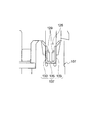
これに対し、特許文献2では、図8に示す電圧検出用端子が開示されている。この電圧検出用端子121は、バスバ101と重ねられるバスバ接触部123と、電線105の芯線と接続される電線接続部125と、これらをつなぐ一対の連結部127を有して形成される。電線接続部125は、2対の圧接片129a,129bが起立して設けられ、これらの間に電線105が圧入されると、各圧接片129a,129bがそれぞれ電線105の絶縁被覆を突き破って芯線(導体)と電気的に接続されるようになっている。
On the other hand, Patent Document 2 discloses a voltage detection terminal shown in FIG. The
図8の電圧検出用端子121は、たとえば、図9に示すように、バスバ接触部123がバスバ101と重ねられた状態で、図7に示すケース107の収容室111に収容される。圧接片129a,129bにそれぞれ圧接された各電線105は、収容室111の囲い壁117に沿って形成される電線収容部129にそれぞれ収容されて配索された後、電線配索路115に引き出される。これによれば、電線105の芯線と電線接続部125との接続部分の空間密度を小さくすることができ、しかも、芯線の露出面積を少なくできるから、電線105の芯線が液に曝されるのを抑制することができる。
For example, as shown in FIG. 9, the
ところで、特許文献2の場合、電圧検出用端子121は、電線接続部125に電線105を圧接するときの圧接方向に負荷がかかり、たとえば、電線接続部125を変形させたり、電圧検出用端子121が位置ずれをおこすおそれがある。このため、特許文献2では、図10に示すように、1対の溝側面133と溝底135とから形成されるケース107の収容溝137に電線接続部125を収容して支持する構造が採用されている。
By the way, in the case of Patent Document 2, the
しかしながら、図10のように、収容溝137に電線接続部125を収容して支持する場合、結露等によって生じた液が、電線接続部125と収容溝137との隙間に溜まりやすくなる。これにより、電線接続部125は、長時間液に曝されることになり、また、隙間に溜まった液が電線接続部125を伝って圧接片129と接続される電線105の芯線と接触するおそれがある。
However, as shown in FIG. 10, when the electric
本発明は、液と電線の導体との接触を抑制することを課題とする。 This invention makes it a subject to suppress the contact with a liquid and the conductor of an electric wire.
上記課題を解決するため、本発明に係るバスバモジュールは、正極と負極が交互に配列された複数の電池の隣り合う正極と負極を接続してこれらの電池を直列に接続する複数のバスバと、これらのバスバとそれぞれ重ねられる複数の端子と、これらの端子にそれぞれ接続される複数の電線と、前記複数のバスバと前記複数の端子と前記複数の電線とを収容する樹脂製のケースとを有し、前記端子は、前記バスバと重ねられるバスバ接触部と、前記電線の導体と電気的に接続される電線接続部とを備え、前記電線接続部は、前記電線の接続端部を支持する底板と、該底板の両側縁から立設された一対の側壁を有し、前記ケースに設けられた第1突起部と第2突起部の間に配置され、前記ケースは、前記電線接続部の底板を当接支持する支持部が形成され、この支持部を除いて前記電線接続部との間に空間が形成されてなるものとする。 In order to solve the above-described problem, a bus bar module according to the present invention includes a plurality of bus bars that connect adjacent positive electrodes and negative electrodes of a plurality of batteries in which positive electrodes and negative electrodes are alternately arranged, and connect these batteries in series. A plurality of terminals that are respectively overlapped with these bus bars, a plurality of electric wires that are respectively connected to these terminals, and a resin case that accommodates the plurality of bus bars, the plurality of terminals, and the plurality of electric wires. The terminal includes a bus bar contact portion that is overlapped with the bus bar, and an electric wire connection portion that is electrically connected to the conductor of the electric wire, and the electric wire connection portion supports a connection end portion of the electric wire. And a pair of side walls erected from both side edges of the bottom plate , and disposed between the first projection and the second projection provided on the case , wherein the case is a bottom plate of the wire connection portion. The support part that contacts and supports Made, it is assumed that the space is formed between the wire connecting portion, except the supporting portion.
これによれば、電線接続部と支持部が当接する面積を小さくすることができるから、電線接続部に沿って液が溜まるのを抑制することができる。よって、電線接続部を伝って電線の芯線に液が接触するのを防ぐことができる。 According to this, since the area where the wire connecting portion and the support portion abut can be reduced, it is possible to suppress the accumulation of liquid along the wire connecting portion. Therefore, it can prevent that a liquid contacts the core wire of an electric wire along an electric wire connection part.
この場合において、前記ケースは、前記支持部を除いて、前記電線接続部と対向する位置に凹み又は開口が形成され、この凹み又は開口は、前記電線接続部と対向する位置の近傍まで連なって形成されるものとする。 In this case, the case is formed with a recess or an opening at a position facing the wire connecting portion except for the support portion, and the recess or opening is continued to a position near the wire connecting portion. Shall be formed.
これによれば、ケースの空間内に電線接続部を設けることができるから、電線接続部に付着した液を、空間を介して排出することができる。よって、電線接続部に沿って液が溜まるのをより確実に抑制することができる。 According to this, since an electric wire connection part can be provided in the space of a case, the liquid adhering to an electric wire connection part can be discharged | emitted through space. Therefore, it can suppress more reliably that a liquid accumulates along an electric wire connection part.
また、端子は、前記電線接続部から突出する弾性部材を有しており、前記弾性部材は、前記電線接続部を前記支持部と当接させたときに、前記ケースの前記支持部と交差して立ち上がる側壁と当接可能に形成され、前記ケースは、前記電線接続部を前記支持部に近づけたときに、前記弾性部材が乗り上げて弾性変形する突起部が前記側壁に設けられ、この突起部は、前記電線接続部が前記ケースに対して正規の位置に収容されたときに、前記弾性部材が弾性復帰して係合されるものとする。 The terminal has an elastic member protruding from the electric wire connecting portion, and the elastic member intersects the supporting portion of the case when the electric wire connecting portion is brought into contact with the supporting portion. The case is formed so as to be able to come into contact with the side wall that rises, and the case is provided with a protrusion on the side wall that is elastically deformed by the elastic member climbing when the wire connection portion is brought close to the support portion. The elastic member is assumed to be elastically restored and engaged when the electric wire connecting portion is accommodated in a normal position with respect to the case.
これによれば、たとえば、電線を電線接続部に接続するときに、電線接続部が支持部側に押し付けられたとしても、弾性部材が側壁を押し付けることから、電線接続部の変形や位置ずれを抑制することができる。 According to this, for example, when the electric wire is connected to the electric wire connecting portion, even if the electric wire connecting portion is pressed against the support portion side, the elastic member presses the side wall. Can be suppressed.
また、前記端子は、前記バスバ接触部と前記電線接続部とが連結部を介して連なって形成され、前記バスバは、前記端子の前記バスバ接触部を重ね合わせたときに、前記連結部と対向する位置とその近傍を切欠いて形成されてなるものとする。 Further, the terminal is formed by connecting the bus bar contact portion and the wire connecting portion via a connecting portion, and the bus bar faces the connecting portion when the bus bar contact portion of the terminal is overlapped. It is assumed that it is formed by cutting out the position to be and its vicinity.
これによれば、連結部とバスバとの隙間を伝って液が移動するのを抑制することができるから、このような液が電線の芯線と接触するのを防ぐことができる。 According to this, since it can suppress that a liquid moves along the clearance gap between a connection part and a bus bar, it can prevent that such a liquid contacts the core wire of an electric wire.
本発明によれば、液と電線の導体との接触を抑制することができる。 ADVANTAGE OF THE INVENTION According to this invention, the contact with a liquid and the conductor of an electric wire can be suppressed.
以下、本発明が適用されるバスバモジュールについて、図面を参照して説明する。本実施形態のバスバモジュールは、たとえば、電動モータの駆動力によって走行する電気自動車や、エンジンと電動モータとの双方の駆動力で走行するハイブリッド車などに搭載され、電動モータに電力を供給する電源装置に適用されるものである。 Hereinafter, a bus bar module to which the present invention is applied will be described with reference to the drawings. The bus bar module of the present embodiment is mounted on, for example, an electric vehicle that travels by the driving force of the electric motor, a hybrid vehicle that travels by the driving force of both the engine and the electric motor, and the power source that supplies power to the electric motor. It is applied to the device.
図1に示すように、本実施形態のバスバモジュール11が取り付けられる電池集合体12は、複数の電池13をその配列方向に重ね合わせて直列に接続して構成される。図1において、矢印Xは、複数の電池13の配列方向、つまり、電池集合体12の長手方向を示す。本実施形態では、図1の右側を電池13の配列方向の奥側、左側を電池13の配列方向の手前側という。矢印Yは、各電池13及び電池集合体12の高さ方向を示す。本実施形態では、高さ方向が重力方向と平行になるように配置され、図1の矢印Yの下方向、つまり、重力方向を下側、矢印Yの上方向を上側という。また、矢印Zは、各電池13の幅方向、つまり、電池集合体12の幅方向を示す。
As shown in FIG. 1, the
各電池13は、それぞれ直方体状に形成され、互いに反対側に位置する面(電極面)のうち一方の面から正極14が突出し、他方の面から負極15が突出している。各電極は、導電性の金属により円柱状に形成され、電極面から垂直に突出している。また、各電極には、それぞれねじ溝が形成されている。
Each
電池集合体12は、隣り合う電池13の正極14と負極15が交互に直線状に配列される。この電池集合体12は、たとえば、直列に接続された偶数個の電池13の両端に位置する電池13のうち、一方の電池13の正極が総正極となり、他方の電池13の負極が総負極となる。なお、本実施形態では、正極14と負極15が各電池13の互いに反対側の面に設けられる例を説明するが、これに限られるものではなく、たとえば、正極14及び負極15が各電池13の1つの面(電極面)に設けられていてもよい。
In the
バスバモジュール11は、複数のバスバ16と、各バスバ16とそれぞれ重ねられる複数の端子である電圧検出用端子17と、これらの電圧検出用端子17にそれぞれ接続される複数の電線18と、この複数のバスバ16と複数の電圧検出用端子17と複数の電線18をそれぞれ収容するケース19を有して構成される。
The
ケース19は、合成樹脂等の成形により形成され、各バスバ16とこのバスバ16と重なる各電圧検出用端子17とが収容される複数の第1収容室20を有している。各第1収容室20は、ケース19の底板21(図2)から筒状に立ち上がる囲い壁22の内側に形成されている。隣り合う第1収容室20は、互いに連結され、電池13の配列方向に並んで配置されている。第1収容室20の底板には、隣り合う電池13の正極14と負極15が通される図示しない電極穴が設けられている。各第1収容室20の下側には、電池13の配列方向に延びる電線配索路23が各第1収容室20と隣接して設けられている。電線配索路23は、矩形状の底板24と、底板24の側縁から互いに略平行に立ち上がる一対の側板25により形成されている。
The
バスバ16は、金属板にプレス加工を施して形成され、隣り合う電池13の正極14と負極15を接続することにより、複数の電池13を直列に接続するものである。このバスバ16は、図2に示すように、金属板に隣り合う正極14と負極15が通される一対のバスバ穴26a,26bが形成される。バスバ16は、第1収容室20の爪部27a〜27dに係止されて嵌め込まれ、底板21の図示しない貫通穴を通された正極14と負極15がそれぞれ一対のバスバ穴26a,26bに通され、この正極14と負極15にそれぞれナット28(図1)が螺合されることで、電池集合体12に固定される。
The
電圧検出用端子17は、金属板にプレス加工を施して形成され、図3に示すように、バスバ16と重ねられて接続されるバスバ接触部29と、電線18と電気的に接続される電線接続部30と、バスバ接触部29と電線接続部30を連結する一対の連結部31a,31bとが一体的に形成されている。この電圧検出用端子17は、バスバ16の電池13の配列方向の奥側に重ねて設けられている。
The
バスバ接触部29は、図3に示すように、板状に形成され、正極14又は負極15のいずれか一方が通される端子穴32と、回り止め用の開口部33が設けられている。なお、開口部33は、ケース19側から突出する図示しない突起部を嵌合させることにより、ナット28を締め付けるときの電圧検出用端子17の回転を規制するためのものであるが、図2に示すように、複数の爪部27で電圧検出用端子17を係止することにより、省略することもできる。
As shown in FIG. 3, the bus
電線接続部30は、図3に示すように、底板34の幅方向の両端部からそれぞれ立設して、互いの間に電線18を位置付ける1対の側板35と、1対の側板35から内側に突出して、電線18の導体と電気的に接続される2対の接続片36a,36bと、底板34の幅方向の両端部からそれぞれ立設して、電線18の絶縁被覆をかしめて電線18を固定する1対のかしめ片37とが一体的に形成されている。
As shown in FIG. 3, the electric
連結部31a,31bは、バスバ接触部29の互いに反対側の側面(電池13の配列方向の両側面)からそれぞれ略垂直に立ち上がり、電線接続部30の互いに反対側の側面(電池13の配索方向の両端面)と連なって形成されている。
The
ケース19は、図2に示すように、囲い壁22に沿って電線18を配索する電線配索部38が設けられている。この電線配索部38は、電池13の配列方向の奥側(図2の右側)の囲い壁22とこの囲い壁22の外側に対向して立設する外壁39との間に形成されている。
As shown in FIG. 2, the
各第1収容室20には、それぞれ第2収容室40が隣接して設けられている。この第2収容室40は、囲い壁22の外側に設けられ、第1収容室20に収容されるバスバ16よりも上側に配置され、かつ、電圧検出用端子17の電線接続部30よりも電池13の配列方向の手前側に配置されている。第2収容室40は、第1収容室20と壁部41を隔てて設けられている。
Each
壁部41は、囲い壁22と同様、ケース19の底板21から立ち上げて形成される。壁部41の上面には、電線接続部30を通した電線18の先端側の端部42を第2収容室40に案内する案内部43が設けられている。この案内部43は、電線18を押し付けて挟持する1対の挟持部44を有している。このように、第1収容室20と壁部41を隔てて設けられた第2収容室40に電線18の先端側の端部42を収容することにより、端部42に液が接触するのを防ぐことができる。
The
次に、本実施形態の特徴構成について説明する。本実施形態において、電圧検出用端子17は、バスバ接触部29がバスバ16に重ねられるとともに、電線接続部30がケース19に当接して支持されている。図4は、図2の右半分を裏側からみた図である。ケース19には、電線接続部30の電線18の配索方向と交差(略直交)する方向に延びる複数(2つ)の支持部45a,45bが設けられている。この支持部45a,45bは、ケース19に形成された矩形状の開口46を架け渡して形成される。すなわち、電線接続部30は、開口46内のケース19の支持部45a,45bにのみ底板34が当接されて支持され、支持部45a,45bに当接されない底板34の面は、開口46を臨むように配置されている。この開口46は、電線接続部30の周囲、つまり、電線接続部30と対向する位置(領域)の近傍まで連なるとともに、支持部45a,45bによって3つの領域に仕切られて形成される。図4の符号47は、ケース19の底板21に形成される電極穴を表している。
Next, the characteristic configuration of the present embodiment will be described. In the present embodiment, the
一方、図2に示すように、ケース19の表側は、連結部31a,31b間とバスバ接触部29と電線接続部30によって囲まれた底板21から、電池13の配列方向に沿って、第1突起部48が立ち上げられている。第1突起部48には、これと略直交するように一対の平板状の立設部49a,49bが互いに略平行に立ち上げられている(図5)。電線接続部30を挟んでケース19の上側の底板21には、電池13の配列方向に沿って、第2突起部50が立ち上げられている。すなわち、電線接続部30は、上下方向において第1突起部48と第2突起部50との間に配置される。
On the other hand, as shown in FIG. 2, the front side of the
図5に示すように、ケース19には、開口46が設けられたことにより、ケース19の厚み方向に貫通する空間51が形成され、この空間51を横切るように、電線接続部30を接触支持する支持部45a,45bが設けられている。すなわち、ケース19は、支持部45を除いて、電線接続部30との間に空間51が形成されている。
As shown in FIG. 5, the
また、電圧検出用端子17は、電線接続部30の底板34からバスバ接触部29と反対側に突出する弾性部材52を有している。この弾性部材52は、電線18の圧入方向(図5の矢印の方向)と反対側に屈曲して立ち上げて形成され、電圧検出用端子17の組み付け時において、支持部45と略直交し、空間51に面する側壁53と当接するようになっている。この側壁53には、電圧検出用端子17の組み付け方向(図5の下方向)に傾斜する傾斜面54と側壁53と略直交する係止面55とを有する突起部56が突出して設けられている。この突起部56は、支持部45に電線接続部30を近づけたときに、弾性部材52を押し付けるように設けられている。
Further, the
このようにして構成されるケース19に電圧検出用端子17を組み付ける場合、電線接続部30は、空間51内に突出する突起部56の傾斜面54に沿って弾性部材52が乗り上げる。これにより、弾性部材52は、屈曲部分を支点として、内側(図5の右側)に折り返される方向に弾性変形する。そして、電線接続部30が空間51内の正規位置、たとえば、電線接続部30が支持部45a,45bと当接する位置に達したときに、弾性部材52の先端部は、突起部56の傾斜面54を乗り越えて弾性復帰する。これにより、弾性部材52の先端部は、側壁53と接触し、かつ、突起部56の係止面55と接触して係合されるため、電圧検出用端子17は、ケース19に係止された状態となる。
When the
次に、ケース19に電線18を配索する手順を説明する。なお、ケース19には、バスバ16と電圧検出用端子17がそれぞれ収容されているものとする。まず、電線18を電圧検出用端子17の電線接続部30、具体的には、1対の接続片36a間と1対の接続片36b間の真上にそれぞれ配置する。また、この電線18の先端側を壁部41の案内部43の真上に配置する。そして、図示しない圧接用の工具を下降させ、電線18を1対の接続片36a間と1対の接続片36b間にそれぞれ圧入する。これにより、各接続片36は電線18の絶縁被覆を突き破って電線18の芯線(導体)に接続される。1対の側板35間に収容された電線18は、底板34と密着された状態となる(図3)。そして、1対のかしめ片37をかしめて電線18を固定した後、この電線18の基端側を折り曲げて電線配索部38に収容し、電線配索部38に通された電線18を電線配索路23に引き出して配索する。
Next, a procedure for routing the
一方、電線接続部30を通した電線18の先端側を1対の挟持部44間に押し込む。これにより、電線18は、1対の挟持部44間に挟持され、電線18の端部42は、第2収容室40に非接触で収容される。
On the other hand, the distal end side of the
以上述べたように、本実施形態では、ケース19を厚み方向に貫く空間51を形成し、その空間51を横切るように設けた支持部45a,45bに、電線接続部30の一部を当接させて支持するようにしているから、電線接続部30を当接支持する面積を少なくすることができる。これにより、電線接続部30の表面に液が溜まりにくくすることができ、また、仮に、電線接続部30の表面に液が溜まったとしても、隣り合う支持部45間は互いに離間して設けられているから、毛細管現象によって、電線接続部30を液が伝って移動するのを妨げることができる。よって、電線18の芯線、つまり、接続片36と接続される電線18の芯線に液が接触するのを抑制することができる。
As described above, in the present embodiment, a
また、ケース19の開口46は、電線接続部30と対向する領域の近傍まで連なって形成されているから、電線接続部30を空間51内に配置することができる。これにより、電線接続部30の表面に付着する液を開口46から排出することができるから、電線18の芯線に液が接触するのをより確実に抑制することができる。
Moreover, since the
また、本実施形態では、電線接続部30から延出させた弾性部材52の先端部を突起部56の係止面55と側壁53の両方にそれぞれ接触させて係止させている。このため、たとえば、図5に示すように、電線18を接続片36a間及び接続片36b間に圧入する際に、電線接続部30が矢印の方向に押し付けられた場合、電線接続部30にわずかの撓みが生じることによって弾性部材52が側壁53をより強く押し付けることから、電線接続部30の撓みを抑制することができ、電線接続部30の変形や位置ずれを防ぐことができる。
Further, in the present embodiment, the distal end portion of the
ところで、電圧検出用端子17は、バスバ接触部29がバスバ16と重なり合っていることから、結露等により生じた液がこれらの隙間に溜まりやすい構造となっている。この場合、バスバ接触部29とバスバ16との隙間に溜まった液が、毛細管現象によって連結部31a,31bを伝って電線接続部30まで移動した場合、電線18の芯線と接触するおそれがある。
By the way, the
図6に、バスバ16を電圧検出用端子17の裏側からみた構造を示す。図に示すように、バスバ16は、電圧検出用端子17のバスバ接触部29を重ね合わせたときに、連結部31a,31bと対向する位置とその近傍に、切欠き部57a,57bを有している。切欠き部57aは、連結部31aと対向する位置に設けられ、バスバ16の辺部を矩形状に切欠いて形成される。切欠き部57bは、連結部31bと対向する位置に設けられ、バスバ16の角部を円弧状に切り欠いて形成される。このように、バスバ16に切欠き部57a,57bを形成することにより、連結部31a,31bがバスバ16と接触するのを防ぐことができる。これにより、バスバ接触部29とバスバ16との間に溜まった液が、各連結部31を伝って、電線接続部30まで移動するのを抑制することができるから、電線18の芯線に液が接触するのを抑制することができる。
FIG. 6 shows a structure in which the
以上、本発明の実施形態を図面により詳述してきたが、上記の実施形態は本発明の例示にしか過ぎないものであり、本発明は上記の実施形態の構成にのみ限定されるものではない。本発明の要旨を逸脱しない範囲の設計の変更などがあっても、本発明に含まれることは勿論である。 As mentioned above, although embodiment of this invention has been explained in full detail with drawing, said embodiment is only an illustration of this invention and this invention is not limited only to the structure of said embodiment. . Needless to say, even if there is a design change within a range not departing from the gist of the present invention, it is included in the present invention.
たとえば、本実施形態では、電線接続部30とケース19との間に空間51を設けるべく、ケース19に開口46を形成する例を説明したが、空間51を形成することができるのであれば、開口46に代えて、たとえば、ケース19に凹み部を設けるようにしてもよい。また、開口46や凹み部の形状は、本実施形態の例に限定されるものではなく、少なくとも、電線接続部30と対向するケース19のいずれかの面に形成されていればよい。
For example, in the present embodiment, the example in which the
また、本実施形態では、2つの支持部45a,45bを設ける例を説明したが、支持部の数は、これに限られるものではなく、1つでもよいし、3つ以上を設けてもよい。
Moreover, although the example which provides the two
また、本実施形態において、電線18は、隣り合う電池13間の電圧を検出する電圧検出用端子17と接続されるが、本発明は、その他の電線、すなわち、その他の機能を有する端子と接続される電線の防水構造としても、適用することができる。
In the present embodiment, the
11 バスバモジュール
12 電池集合体
13 電池
14 正極
15 負極
16 バスバ
17 電圧検出用端子
18 電線
19 ケース
20 第1収容室
21 底板
22 囲い壁
29 バスバ接触部
30 電線接続部
31a,31b 連結部
36a,36b 接続片
45a,45b 支持部
46 開口
51 空間
52 弾性部材
53 側壁
56 突起部
57 切欠き部
DESCRIPTION OF
Claims (5)
前記端子は、前記バスバと重ねられるバスバ接触部と、前記電線の導体と電気的に接続される電線接続部とを備え、
前記電線接続部は、前記電線の接続端部を支持する底板と、該底板の両側縁から立設された一対の側壁を有し、前記ケースに設けられた第1突起部と第2突起部の間に配置され、
前記ケースは、前記電線接続部の前記底板を当接支持する支持部が形成され、この支持部を除いて前記電線接続部との間に空間が形成されてなるバスバモジュール。 A plurality of bus bars that connect adjacent positive electrodes and negative electrodes of a plurality of batteries in which positive electrodes and negative electrodes are alternately arranged and connect these batteries in series, a plurality of terminals that are respectively overlapped with these bus bars, and these terminals A plurality of electric wires connected to each other, a plurality of bus bars, a plurality of terminals, and a resin case that accommodates the plurality of electric wires,
The terminal includes a bus bar contact portion that is overlapped with the bus bar, and a wire connection portion that is electrically connected to a conductor of the wire.
The electric wire connecting portion includes a bottom plate that supports a connecting end portion of the electric wire, and a pair of side walls that are erected from both side edges of the bottom plate, and a first protruding portion and a second protruding portion that are provided on the case. Placed between
The case is a bus bar module in which a support portion that abuts and supports the bottom plate of the wire connection portion is formed, and a space is formed between the case and the wire connection portion except for the support portion.
前記弾性部材は、前記電線接続部を前記支持部と当接させたときに、前記ケースの前記支持部と交差して立ち上がる側壁と当接可能に形成され、
前記ケースは、前記電線接続部を前記支持部に近づけたときに、前記弾性部材が乗り上げて弾性変形する突起部が前記側壁に設けられ、この突起部は、前記電線接続部が前記ケースに対して正規の位置に収容されたときに、前記弾性部材が弾性復帰して係合される請求項1又は2に記載のバスバモジュール。 The terminal has an elastic member protruding from the electric wire connecting portion,
The elastic member is formed so as to be able to come into contact with a side wall that rises across the support portion of the case when the wire connection portion is brought into contact with the support portion.
The case is provided with a protrusion on the side wall that is elastically deformed when the elastic member rides when the wire connection portion is brought close to the support portion, and the protrusion is connected to the case with respect to the case. The bus bar module according to claim 1 or 2, wherein the elastic member is elastically restored and engaged when housed in a normal position.
前記バスバは、前記端子の前記バスバ接触部を重ね合わせたときに、前記連結部と対向する位置とその近傍を切欠いて形成される請求項1乃至3のいずれかに記載のバスバモジュール。 The terminal is formed by connecting the bus bar contact portion and the wire connecting portion via a connecting portion,
The bus bar module according to any one of claims 1 to 3, wherein the bus bar is formed by notching a position facing the connecting portion and its vicinity when the bus bar contact portions of the terminals are overlapped.
Priority Applications (1)
| Application Number | Priority Date | Filing Date | Title |
|---|---|---|---|
| JP2013165421A JP6317898B2 (en) | 2013-08-08 | 2013-08-08 | Bus bar module |
Applications Claiming Priority (1)
| Application Number | Priority Date | Filing Date | Title |
|---|---|---|---|
| JP2013165421A JP6317898B2 (en) | 2013-08-08 | 2013-08-08 | Bus bar module |
Publications (2)
| Publication Number | Publication Date |
|---|---|
| JP2015035323A JP2015035323A (en) | 2015-02-19 |
| JP6317898B2 true JP6317898B2 (en) | 2018-04-25 |
Family
ID=52543718
Family Applications (1)
| Application Number | Title | Priority Date | Filing Date |
|---|---|---|---|
| JP2013165421A Active JP6317898B2 (en) | 2013-08-08 | 2013-08-08 | Bus bar module |
Country Status (1)
| Country | Link |
|---|---|
| JP (1) | JP6317898B2 (en) |
Families Citing this family (6)
| Publication number | Priority date | Publication date | Assignee | Title |
|---|---|---|---|---|
| JP6720852B2 (en) | 2016-12-22 | 2020-07-08 | 株式会社オートネットワーク技術研究所 | Bus bar, power storage module, and wiring module |
| JP6856386B2 (en) * | 2017-01-17 | 2021-04-07 | 矢崎総業株式会社 | Wire distribution method |
| CN106735096B (en) * | 2017-01-24 | 2018-09-28 | 浙江海悦自动化机械股份有限公司 | A kind of busbar cast welding mold |
| JP6574796B2 (en) | 2017-01-31 | 2019-09-11 | 矢崎総業株式会社 | Busbar holding structure |
| JP6574814B2 (en) * | 2017-06-16 | 2019-09-11 | 矢崎総業株式会社 | Conductor module mounting structure |
| JP6440004B1 (en) * | 2018-03-26 | 2018-12-19 | 株式会社オートネットワーク技術研究所 | Connection module |
Family Cites Families (8)
| Publication number | Priority date | Publication date | Assignee | Title |
|---|---|---|---|---|
| US8449333B2 (en) * | 2009-10-06 | 2013-05-28 | Yazaki Corporation | Battery connecting structure |
| JP5632193B2 (en) * | 2010-05-11 | 2014-11-26 | 矢崎総業株式会社 | Battery connecting member and battery connecting body |
| JP5554757B2 (en) * | 2011-07-28 | 2014-07-23 | 矢崎総業株式会社 | Battery pack |
| JP5609825B2 (en) * | 2011-09-05 | 2014-10-22 | トヨタ自動車株式会社 | Battery connection unit and power supply device |
| JP5834769B2 (en) * | 2011-10-26 | 2015-12-24 | 株式会社オートネットワーク技術研究所 | Battery wiring module |
| JP5741948B2 (en) * | 2011-11-11 | 2015-07-01 | 株式会社オートネットワーク技術研究所 | Battery wiring module |
| JP5817535B2 (en) * | 2012-01-06 | 2015-11-18 | 株式会社オートネットワーク技術研究所 | Wiring module |
| JP6220547B2 (en) * | 2013-05-08 | 2017-10-25 | 矢崎総業株式会社 | Bus bar module |
-
2013
- 2013-08-08 JP JP2013165421A patent/JP6317898B2/en active Active
Also Published As
| Publication number | Publication date |
|---|---|
| JP2015035323A (en) | 2015-02-19 |
Similar Documents
| Publication | Publication Date | Title |
|---|---|---|
| JP6317898B2 (en) | Bus bar module | |
| JP6085140B2 (en) | Bus bar module wiring structure | |
| JP6372620B2 (en) | Terminal and wiring module | |
| JP5779010B2 (en) | Bus bar module structure | |
| JP5494748B2 (en) | Battery wiring module | |
| WO2014014000A1 (en) | Bus bar module | |
| JP6032897B2 (en) | Power supply | |
| CN108140799B (en) | Power storage module and battery connection module | |
| JP6068059B2 (en) | Bus bar module | |
| JP6365437B2 (en) | Wiring module and power storage module | |
| US20180261822A1 (en) | Terminal and wiring module | |
| EP3098878B1 (en) | Wiring module | |
| WO2014192857A1 (en) | Electrical wire routing device | |
| JP2013080620A (en) | Battery wiring module | |
| JP2014146489A (en) | Bus bar module and power supply device | |
| JP7256079B2 (en) | Electric wire holding structure and busbar module | |
| JP2013020815A (en) | Battery wiring module | |
| JP6158635B2 (en) | Bus bar module | |
| JP7152364B2 (en) | Electric wire holding structure and busbar module | |
| WO2016194803A1 (en) | Wiring module | |
| JP6351395B2 (en) | Busbar module | |
| JP7183996B2 (en) | battery wiring module | |
| JP2024019921A (en) | battery wiring module |
Legal Events
| Date | Code | Title | Description |
|---|---|---|---|
| A621 | Written request for application examination |
Free format text: JAPANESE INTERMEDIATE CODE: A621 Effective date: 20160719 |
|
| A977 | Report on retrieval |
Free format text: JAPANESE INTERMEDIATE CODE: A971007 Effective date: 20170419 |
|
| A131 | Notification of reasons for refusal |
Free format text: JAPANESE INTERMEDIATE CODE: A131 Effective date: 20170516 |
|
| A521 | Request for written amendment filed |
Free format text: JAPANESE INTERMEDIATE CODE: A523 Effective date: 20170714 |
|
| A131 | Notification of reasons for refusal |
Free format text: JAPANESE INTERMEDIATE CODE: A131 Effective date: 20170905 |
|
| A521 | Request for written amendment filed |
Free format text: JAPANESE INTERMEDIATE CODE: A523 Effective date: 20171030 |
|
| A131 | Notification of reasons for refusal |
Free format text: JAPANESE INTERMEDIATE CODE: A131 Effective date: 20171205 |
|
| A521 | Request for written amendment filed |
Free format text: JAPANESE INTERMEDIATE CODE: A523 Effective date: 20180130 |
|
| TRDD | Decision of grant or rejection written | ||
| A01 | Written decision to grant a patent or to grant a registration (utility model) |
Free format text: JAPANESE INTERMEDIATE CODE: A01 Effective date: 20180306 |
|
| A61 | First payment of annual fees (during grant procedure) |
Free format text: JAPANESE INTERMEDIATE CODE: A61 Effective date: 20180402 |
|
| R150 | Certificate of patent or registration of utility model |
Ref document number: 6317898 Country of ref document: JP Free format text: JAPANESE INTERMEDIATE CODE: R150 |
|
| R250 | Receipt of annual fees |
Free format text: JAPANESE INTERMEDIATE CODE: R250 |
|
| R250 | Receipt of annual fees |
Free format text: JAPANESE INTERMEDIATE CODE: R250 |
|
| R250 | Receipt of annual fees |
Free format text: JAPANESE INTERMEDIATE CODE: R250 |
|
| S531 | Written request for registration of change of domicile |
Free format text: JAPANESE INTERMEDIATE CODE: R313531 |
|
| R350 | Written notification of registration of transfer |
Free format text: JAPANESE INTERMEDIATE CODE: R350 |
|
| R250 | Receipt of annual fees |
Free format text: JAPANESE INTERMEDIATE CODE: R250 |