JP6302279B2 - Rotating equipment - Google Patents
Rotating equipment Download PDFInfo
- Publication number
- JP6302279B2 JP6302279B2 JP2014031932A JP2014031932A JP6302279B2 JP 6302279 B2 JP6302279 B2 JP 6302279B2 JP 2014031932 A JP2014031932 A JP 2014031932A JP 2014031932 A JP2014031932 A JP 2014031932A JP 6302279 B2 JP6302279 B2 JP 6302279B2
- Authority
- JP
- Japan
- Prior art keywords
- protector
- casing
- angle
- opening
- casing surface
- Prior art date
- Legal status (The legal status is an assumption and is not a legal conclusion. Google has not performed a legal analysis and makes no representation as to the accuracy of the status listed.)
- Active
Links
- 230000001012 protector Effects 0.000 claims description 150
- 239000000463 material Substances 0.000 claims description 3
- 230000005489 elastic deformation Effects 0.000 description 4
- 230000008878 coupling Effects 0.000 description 3
- 238000010168 coupling process Methods 0.000 description 3
- 238000005859 coupling reaction Methods 0.000 description 3
- 238000007689 inspection Methods 0.000 description 3
- 238000012423 maintenance Methods 0.000 description 3
- 238000012360 testing method Methods 0.000 description 3
- 230000000694 effects Effects 0.000 description 2
- 239000013013 elastic material Substances 0.000 description 2
- 238000011156 evaluation Methods 0.000 description 2
- 238000000034 method Methods 0.000 description 2
- 238000012986 modification Methods 0.000 description 2
- 230000004048 modification Effects 0.000 description 2
- 239000003638 chemical reducing agent Substances 0.000 description 1
- 239000000470 constituent Substances 0.000 description 1
- 238000009434 installation Methods 0.000 description 1
- 239000007788 liquid Substances 0.000 description 1
- 239000002184 metal Substances 0.000 description 1
- 239000011347 resin Substances 0.000 description 1
- 229920005989 resin Polymers 0.000 description 1
- 238000007789 sealing Methods 0.000 description 1
- 210000001364 upper extremity Anatomy 0.000 description 1
Images


Classifications
-
- F—MECHANICAL ENGINEERING; LIGHTING; HEATING; WEAPONS; BLASTING
- F16—ENGINEERING ELEMENTS AND UNITS; GENERAL MEASURES FOR PRODUCING AND MAINTAINING EFFECTIVE FUNCTIONING OF MACHINES OR INSTALLATIONS; THERMAL INSULATION IN GENERAL
- F16P—SAFETY DEVICES IN GENERAL; SAFETY DEVICES FOR PRESSES
- F16P1/00—Safety devices independent of the control and operation of any machine
- F16P1/02—Fixed screens or hoods
-
- F—MECHANICAL ENGINEERING; LIGHTING; HEATING; WEAPONS; BLASTING
- F04—POSITIVE - DISPLACEMENT MACHINES FOR LIQUIDS; PUMPS FOR LIQUIDS OR ELASTIC FLUIDS
- F04D—NON-POSITIVE-DISPLACEMENT PUMPS
- F04D13/00—Pumping installations or systems
- F04D13/02—Units comprising pumps and their driving means
-
- F—MECHANICAL ENGINEERING; LIGHTING; HEATING; WEAPONS; BLASTING
- F04—POSITIVE - DISPLACEMENT MACHINES FOR LIQUIDS; PUMPS FOR LIQUIDS OR ELASTIC FLUIDS
- F04D—NON-POSITIVE-DISPLACEMENT PUMPS
- F04D15/00—Control, e.g. regulation, of pumps, pumping installations or systems
- F04D15/02—Stopping of pumps, or operating valves, on occurrence of unwanted conditions
Description
本発明は、回転機器のケーシングに形成された開口部を塞ぐための技術に関する。 The present invention relates to a technique for closing an opening formed in a casing of a rotating device.
回転機器のケーシングには、保守・点検の目的で開口部が設けられることがある。かかる開口部は、通常時は、人の上肢(例えば手)が挿入されて回転部分に接触することから保護するために、着脱可能なプロテクタによって塞がれており、保守・点検が必要となったときに、プロテクタが取り外される。 The casing of the rotating device may be provided with an opening for maintenance and inspection purposes. Such an opening is normally closed by a removable protector to protect a person's upper limb (for example, a hand) from being inserted into contact with the rotating part, and requires maintenance and inspection. The protector is removed.
上述したプロテクタは、JISに規定された安全距離の基準を満たす必要があることは勿論であるが、それに加えて、着脱作業が容易に行えることが望まれる。また、回転機器の運転に伴うプロテクタの振動・騒音を極力抑制することが望ましい。 The protector described above needs to satisfy the safety distance standard defined in JIS. In addition, it is desirable that the protector can be easily attached and detached. It is also desirable to suppress as much as possible the vibration and noise of the protector that accompany the operation of the rotating equipment.
本発明は、上述の課題の少なくとも一部を解決するためになされたものであり、例えば、以下の形態として実現することが可能である。 SUMMARY An advantage of some aspects of the invention is to solve at least a part of the problems described above, and the invention can be implemented as, for example, the following forms.
本発明の第1の形態によれば、回転機器が提供される。この回転機器は、開口部が形成された第1のケーシング面と、第1のケーシング面に隣接する第2のケーシング面であって、第1のケーシング面と角度θ1で交差する第2のケーシング面と、を有するケーシングと、開口部を塞ぐためのプロテクタであって、第1のプロテクタ面と、第1のプロテクタ面に隣接する第2のプロテクタ面であって、第1のプロテクタ面と角度θ2で交差する第2のプロテクタ面と、を有するプロテクタと、を備える。プロテクタは、第2のケーシング面のみに固定されるように構成される。プロテクタがケーシングから取り外された状態において、角度θ2は、角度θ1よりも大きい。プロテクタは、第2のプロテクタ面が第2のケーシング面に固定され、第1のプロテクタ面が弾性変形して、第1のプロテクタ面の第2のプロテクタ面と反対側の縁部が第1のケーシング面に密着した状態でケーシングに取り付けられるように構成される。 According to the first aspect of the present invention, a rotating device is provided. The rotating device includes a first casing surface having an opening and a second casing surface adjacent to the first casing surface, the second casing intersecting the first casing surface at an angle θ1. A casing having a surface, and a protector for closing the opening, the first protector surface, and a second protector surface adjacent to the first protector surface, the first protector surface being at an angle and a protector having a second protector surface intersecting at θ2. The protector is configured to be fixed only to the second casing surface. In a state where the protector is removed from the casing, the angle θ2 is larger than the angle θ1. In the protector, the second protector surface is fixed to the second casing surface, the first protector surface is elastically deformed, and the edge of the first protector surface opposite to the second protector surface is the first protector. It is configured to be attached to the casing in close contact with the casing surface.
かかる回転機器によれば、ケーシングの第2のケーシング面のみにプロテクタを固定することによって、プロテクタをケーシングに取り付けることができる。したがって、ケーシングの複数の面でプロテクタを固定する場合と比べて、プロテクタの着脱作業が非常に容易である。しかも、プロテクタは、弾性変形によって第1のプロテクタ面の縁部が第1のケーシング面に密着した状態でケーシングに取り付けられる。つまり、プロテクタは、第1のプロテクタ面が弾性変形の復元力によって第1のケーシング面を押圧した状態で、ケーシングに取り付けられることができる。したがって、回転機器の運転に伴って生じるプロテクタの振動・騒音を抑制できる。 According to such a rotating device, the protector can be attached to the casing by fixing the protector only to the second casing surface of the casing. Therefore, the attaching / detaching operation of the protector is very easy as compared with the case where the protector is fixed on the plurality of surfaces of the casing. And a protector is attached to a casing in the state which the edge of the 1st protector surface closely_contact | adhered to the 1st casing surface by elastic deformation. That is, the protector can be attached to the casing in a state in which the first protector surface presses the first casing surface by the restoring force of elastic deformation. Therefore, it is possible to suppress the vibration and noise of the protector that occur with the operation of the rotating device.
本発明の第2の形態によれば、回転機器が提供される。この回転機器は、開口部が形成された第1のケーシング面と、第1のケーシング面に隣接する第2のケーシング面であっ
て、第1のケーシング面と角度θ1で交差する第2のケーシング面と、を有するケーシングと、開口部を塞ぐためのプロテクタであって、第1のプロテクタ面と、プロテクタ面に隣接する第2のプロテクタ面であって、第1のプロテクタ面と角度θ2で交差する第2のプロテクタ面と、を有するプロテクタと、を備える。プロテクタは、第1のケーシング面および第2のケーシング面のうちの第2のケーシング面のみに、固定されるように構成される。プロテクタは、弾性を有する材料によって形成されている。角度θ1および角度θ2は、プロテクタがケーシングから取り外された状態において、θ1+5≦θ2≦θ1+15を満たす。かかる回転機器によれば、第1の形態と同様の効果を奏する。
According to the second aspect of the present invention, a rotating device is provided. The rotating device includes a first casing surface having an opening and a second casing surface adjacent to the first casing surface, the second casing intersecting the first casing surface at an angle θ1. A casing having a surface, and a protector for closing the opening, the first protector surface and a second protector surface adjacent to the protector surface, intersecting the first protector surface at an angle θ2. A protector having a second protector surface. The protector is configured to be fixed only to the second casing surface of the first casing surface and the second casing surface. The protector is made of an elastic material. The angles θ1 and θ2 satisfy θ1 + 5 ≦ θ2 ≦ θ1 + 15 when the protector is removed from the casing. According to such a rotating device, the same effects as in the first embodiment can be obtained.
本発明の第3の形態によれば、第1または第2の形態において、第2のプロテクタ面には、雄ネジを挿入するための孔部が、第1のプロテクタ面と反対の側が切り欠かれて形成されている。かかる形態によれば、ケーシングに雄ネジを仮締めした後に、プロテクタをケーシング上に位置決めできるので、位置決め作業が容易になる。また、第2のプロテクタ面が第2のケーシング面に対して傾いた状態でプロテクタを位置決めし、その後、雄ネジを本締めすれば、第1のプロテクタ面が自然に弾性変形するので、プロテクタの取り付け作業がいっそう容易になる。 According to the third aspect of the present invention, in the first or second aspect, the second protector surface is provided with a hole for inserting a male screw, and the side opposite to the first protector surface is notched. It is formed. According to this form, since the protector can be positioned on the casing after temporarily tightening the male screw on the casing, positioning work is facilitated. In addition, if the protector is positioned with the second protector surface tilted with respect to the second casing surface, and then the male screw is finally tightened, the first protector surface is naturally elastically deformed. Installation work becomes easier.
本発明の第4の形態によれば、第1ないし第3の形態のいずれかにおいて、プロテクタは、1つの雄ネジのみによってケーシングに固定される。かかる形態によれば、プロテクタを1点留めでケーシングに固定することができるので、プロテクタの取り付け作業がいっそう容易になる。 According to the fourth aspect of the present invention, in any one of the first to third aspects, the protector is fixed to the casing by only one male screw. According to such a form, the protector can be fixed to the casing at one point, so that the protector can be attached more easily.
A.実施例: A. Example:
図1は、本発明の一実施例としてのポンプシステム10の概略構成を示す。図示するように、ポンプシステム10は、モータ11とカップリング12とポンプ20とを備えている。モータ11とポンプ20とは、カップリング12(図1では、ガード内に収容されている)を介して連結されている。ポンプ20には、ポンプ軸受(図示省略)を取り囲む軸受ケーシング30が設けられている。軸受ケーシング30は、鉛直方向に延在する第1のケーシング面31と、第1のケーシング面31と隣接し(交わり)、水平方向(鉛直方向と直交する方向)に延在する第2のケーシング面32と、を備えている。第1のケーシング面31には、開口部33が形成されている。この開口部33は、軸受ケーシング30に収容されたポンプ軸封部分の保守・点検を行うために設けられている。
FIG. 1 shows a schematic configuration of a pump system 10 as an embodiment of the present invention. As illustrated, the pump system 10 includes a motor 11, a
図2は、図1に示す軸受ケーシング30にプロテクタ50が取り付けられた状態を示す。図示するように、軸受ケーシング30の開口部33は、プロテクタ50によって完全に塞がれている。通常、軸受ケーシング30には、図2に示すようにプロテクタ50が取り付けられており、軸封部分の保守・点検が必要な際にのみプロテクタ50が取り外される。
FIG. 2 shows a state where the
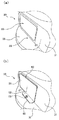
図3は、プロテクタ50が取り付けられる前後の開口部33の周辺を示す拡大図である。図3(a)は、プロテクタ50の取付前の状態を示し、図3(b)は、取付後の状態を示す。図4は、軸受ケーシング30から取り外された状態のプロテクタ50を示す。図3(a)に示すように、第1のケーシング面31と第2のケーシング面32とは、角度θ1(本実施例では90°)で交わっている。第1のケーシング面31の開口部33は、略矩形形状を有しており、その下端は、第1のケーシング面31の下端、すなわち、第1のケーシング面31と第2のケーシング面32との交差線のところで終端している。第2のケーシング面32には、第1のケーシング面31の近傍に1つのボルト孔36が形成されている。なお、開口部33の形状および第1のケーシング面31上の位置は、任意の形状および位置とすることができる。また、ボルト孔36の位置は、第1のプロテクタ面51に撓みを生じさせるために(詳細は後述する)、第1のケーシング面31と第2のケーシング面32との交差線に近いほど望ましい。
FIG. 3 is an enlarged view showing the periphery of the
図4に示すように、プロテクタ50は、略L字形状を有しており、第1のプロテクタ面51と第2のプロテクタ面52とを有している。第1のプロテクタ面51と第2のプロテクタ面52とは、隣接しており、角度θ2で交わっている。角度θ2は、角度θ1よりも若干大きく、θ1,θ2は、本実施例では、次式(1)を満たす関係にある。角度θ1が90°の場合、角度θ2は、95°以上かつ105°以下で設定される。本実施例では、角度θ2は、98°である。
θ1+5≦θ2≦θ1+15・・・(1)
As shown in FIG. 4, the
θ1 + 5 ≦ θ2 ≦ θ1 + 15 (1)
図4に示すように、第2のプロテクタ面52には、雄ネジ(本実施例ではボルト60)を挿入するための孔部53が形成されている。この孔部53は、第1のプロテクタ面51と反対の側が第2のプロテクタ面52の縁部まで切り欠かれて、略U字状に形成されている。孔部53の第1のプロテクタ面51側の端部の位置は、第1のプロテクタ面51に撓みを生じさせるために(詳細は後述する)、第1のプロテクタ面51と第2のプロテクタ面52との交差線に近いほど望ましい。このプロテクタ50は、弾性を有する材料によって形成されている。本実施例では、プロテクタ50の材料は、金属であるが、弾性を有する任意の材料、例えば、樹脂などであってもよい。
As shown in FIG. 4, the
かかるプロテクタ50は、例えば、以下のようにして、軸受ケーシング30に取り付けることができる。まず、ボルト孔36にボルト60が仮締めされる。次に、ボルト60が孔部53の第1のケーシング面31側の端部付近に位置するように、プロテクタ50が配置される。このとき、第1のプロテクタ面51と第2のプロテクタ面52とが交差する角度θ2は、第1のケーシング面31と第2のケーシング面32とが交差する角度θ1よりも大きいので、第2のプロテクタ面52は、その第1のプロテクタ面51側が第2のケーシング面32に対して隙間が生じた状態になる。この状態でボルト60が本締めされるにしたがって、上記隙間が徐々に低減される。これによって、第1のプロテクタ面51の第2のプロテクタ面52と反対側の縁部が、第1のケーシング面31に当接し、第1のプロテクタ面51が、角度θ2が小さくなる方向に撓んで弾性変形し、角度θ2は、図3(b)に示すように最終的におよそθ1まで弾性変形する。このとき、第1のプロテクタ面51の第2のプロテクタ面52と反対側の縁部は、第1のプロテクタ面51の弾性変形に対する復元力によって、第1のケーシング面31と密着する。
The
以上説明したポンプシステム10によれば、第2のケーシング面32のみにプロテクタ50を固定することによって、プロテクタ50を軸受ケーシング30に取り付けることができる。したがって、軸受ケーシング30の第1のケーシング面31および第2のケーシング面32の両方でプロテクタ50を固定する場合と比べて、プロテクタ50の着脱作業が非常に容易である。しかも、プロテクタ50は、第1のプロテクタ面51が弾性変形の
復元力によって第1のケーシング面31を押圧した状態で、軸受ケーシング30に取り付けられる。したがって、ポンプシステム10の運転に伴って生じるプロテクタ50の振動・騒音を抑制できる。
According to the pump system 10 described above, the
また、ポンプシステム10によれば、孔部53が切り欠き形状を有していることによって、ボルト孔36にボルト60を仮締めした後に、プロテクタ50を第2のケーシング面32上に位置決めできるので、位置決め作業が容易になる。また、第2のプロテクタ面52が第2のケーシング面32に対して傾いた状態でプロテクタ50を位置決めし、その後、ボルト60を本締めすることによって、第1のプロテクタ面51が自然に弾性変形するので、プロテクタ50の取り付け作業がいっそう容易になる。
Further, according to the pump system 10, since the
さらに、ポンプシステム10によれば、1つのボルト60のみで、すなわち、1点留めでプロテクタ50を軸受ケーシング30に固定することができるので、プロテクタ50の取り付け作業がいっそう容易になる。
Furthermore, according to the pump system 10, the
図5は、プロテクタ50について、第1のプロテクタ面51と第2のプロテクタ面52とが交差する角度θ2についての評価試験結果を示す。本試験では、厚み1mmのSUS304製のプロテクタ50と、第1のケーシング面31と第2のケーシング面32とが交差する角度θ1が90°の軸受ケーシング30と、を用いて、複数の角度θ2の各々について、密着条件と弾性条件について評価を行った。密着条件および弾性条件は、以下の通りである。
密着条件:プロテクタ50が軸受ケーシング30にネジ固定された状態において、第1のプロテクタ面51の第2のプロテクタ面52と反対側の縁部が第1のケーシング面31に密着すること。
弾性条件:プロテクタ50が軸受ケーシング30にネジ固定された状態において、第1のプロテクタ面51が弾性変形していること(弾性範囲内で変形が生じており、塑性変形が生じていないこと)。
FIG. 5 shows the evaluation test results for the angle θ <b> 2 at which the
Contact condition: The edge of the
Elasticity condition: The
図示するように、角度θ2が95°以上、かつ、105°以下の場合に、換言すれば、角度θ2が角度θ1よりも5°〜15°の任意の角度だけ大きい場合に、密着条件および弾性条件の両方を満たす結果が得られた。この結果は、角度θ1が90°の場合に限らず、概して、任意の角度θ1について適用される。 As shown in the figure, when the angle θ2 is 95 ° or more and 105 ° or less, in other words, when the angle θ2 is larger than the angle θ1 by an arbitrary angle of 5 ° to 15 °, the adhesion condition and the elasticity Results were obtained that met both conditions. This result is not limited to the case where the angle θ1 is 90 °, but generally applies to an arbitrary angle θ1.
B.変形例:
B−1.変形例1:
軸受ケーシング30の開口部は、2つの面に亘って形成されていてもよい。この場合、開口部は、プロテクタの2つの面によって塞がれてもよい。図6は、連続する2つの開口部をプロテクタで塞ぐ場合の実施形態を示す。図示するように、軸受ケーシング130は、第1のケーシング面131と第2のケーシング面132とを有している。第1のケーシング面131には、開口部133が形成されており、第2のケーシング面132には、開口部134が形成されている。第2のケーシング面132の開口部134の両脇には、第1のケーシング面131に近接した位置にボルト孔137,138が形成されている。開口部133と開口部134とは、連続的に形成されている。かかる開口部133,134を塞ぐためのプロテクタ150は、第1のプロテクタ面151と第2のプロテクタ面152とを有している。第2のプロテクタ面152には、開口部134の両脇に2つの孔部156,157が形成されている。かかるプロテクタ150は、上述した手順によって、ボルト161,162によって、軸受ケーシング130に固定される。その結果、開口部133が第1のプロテクタ面151によって塞がれ、開口部134が第2のプロテクタ面152によって塞がれる。
B. Variations:
B-1. Modification 1:
The opening of the bearing
B−2.変形例2:
上述したプロテクタ50,150は、種々の回転機器に使用可能である。こうした回転機器としては、例えば、液体用攪拌機、遠心送排風機、軽荷重用コンベア、発電機、ウォームギア減速機、コンベア、ホイスト、エレベータ、ラインシャフト、ホールミル、レシプロ式コンプレッサ、ハンマーミル、クラッシャ、舶用プロペラなどを例示できる。
B-2. Modification 2:
The above-described
以上、いくつかの実施例に基づいて本発明の実施の形態について説明してきたが、上記した発明の実施の形態は、本発明の理解を容易にするためのものであり、本発明を限定するものではない。本発明は、その趣旨を逸脱することなく、変更、改良され得るとともに、本発明にはその等価物が含まれることはもちろんである。また、上述した課題の少なくとも一部を解決できる範囲、または、効果の少なくとも一部を奏する範囲において、特許請求の範囲および明細書に記載された各構成要素の任意の組み合わせ、または、省略が可能である。 The embodiments of the present invention have been described above based on some examples. However, the above-described embodiments of the present invention are for facilitating the understanding of the present invention and limit the present invention. It is not a thing. The present invention can be changed and improved without departing from the gist thereof, and the present invention includes the equivalents thereof. In addition, any combination or omission of each constituent element described in the claims and the specification is possible within a range where at least a part of the above-described problems can be solved or a range where at least a part of the effect is achieved. It is.
10…ポンプシステム
11…モータ
12…カップリング
20…ポンプ
30,130…軸受ケーシング
31,131…第1のケーシング面
32,132…第2のケーシング面
33,133,134…開口部
36,137,138…ボルト孔
50,150…プロテクタ
51,151…第1のプロテクタ面
52,152…第2のプロテクタ面
53,156,157…孔部
60,161,162…ボルト
DESCRIPTION OF SYMBOLS 10 ... Pump system 11 ...
Claims (4)
開口部が形成された第1のケーシング面と、該第1のケーシング面に隣接する第2のケーシング面であって、前記第1のケーシング面と角度θ1で交差する第2のケーシング面と、を有するケーシングと、
前記開口部を塞ぐためのプロテクタであって、第1のプロテクタ面と、該第1のプロテクタ面に隣接する第2のプロテクタ面であって、前記第1のプロテクタ面と角度θ2で交差する第2のプロテクタ面と、を有するプロテクタと
を備え、
前記プロテクタは、前記第2のケーシング面のみに固定されるように構成され、
前記プロテクタが前記ケーシングから取り外された状態において、前記角度θ2は、前記角度θ1よりも大きく、
前記プロテクタは、前記第2のプロテクタ面が前記第2のケーシング面に固定され、前記第1のプロテクタ面が弾性変形して、該第1のプロテクタ面の前記第2のプロテクタ面と反対側の縁部が前記第1のケーシング面に密着した状態で前記ケーシングに取り付けられるように構成された
回転機器。 A rotating device,
A first casing surface in which an opening is formed, and a second casing surface adjacent to the first casing surface, the second casing surface intersecting the first casing surface at an angle θ1, A casing having
A protector for closing the opening, which is a first protector surface and a second protector surface adjacent to the first protector surface, and intersects the first protector surface at an angle θ2. A protector having two protector surfaces,
The protector is configured to be fixed only to the second casing surface,
In a state where the protector is removed from the casing, the angle θ2 is larger than the angle θ1.
In the protector, the second protector surface is fixed to the second casing surface, the first protector surface is elastically deformed, and the first protector surface is opposite to the second protector surface. A rotating device configured to be attached to the casing in a state in which an edge portion is in close contact with the first casing surface.
開口部が形成された第1のケーシング面と、該第1のケーシング面に隣接する第2のケーシング面であって、前記第1のケーシング面と角度θ1で交差する第2のケーシング面と、を有するケーシングと、
前記開口部を塞ぐためのプロテクタであって、第1のプロテクタ面と、該プロテクタ面に隣接する第2のプロテクタ面であって、前記第1のプロテクタ面と角度θ2で交差する第2のプロテクタ面と、を有するプロテクタと
を備え、
前記プロテクタは、前記第1のケーシング面および前記第2のケーシング面のうちの前記第2のケーシング面のみに、固定されるように構成され、
前記プロテクタは、弾性を有する材料によって形成されており、
前記角度θ1および前記角度θ2は、前記プロテクタが前記ケーシングから取り外された状態において、θ1+5≦θ2≦θ1+15を満たす
回転機器。 A rotating device,
A first casing surface in which an opening is formed, and a second casing surface adjacent to the first casing surface, the second casing surface intersecting the first casing surface at an angle θ1, A casing having
A protector for closing the opening, which is a first protector surface and a second protector surface adjacent to the protector surface, the second protector intersecting the first protector surface at an angle θ2. A protector having a surface, and
The protector is configured to be fixed only to the second casing surface of the first casing surface and the second casing surface,
The protector is formed of a material having elasticity,
The angle θ1 and the angle θ2 satisfy θ1 + 5 ≦ θ2 ≦ θ1 + 15 when the protector is detached from the casing.
前記第2のプロテクタ面には、雄ネジを挿入するための孔部が、前記第1のプロテクタ面と反対の側が切り欠かれて形成されている
回転機器。 The rotating device according to claim 1 or 2,
A hole for inserting a male screw is formed in the second protector surface by cutting away the side opposite to the first protector surface.
前記プロテクタは、1つの雄ネジのみによって前記ケーシングに固定される
回転機器。 The rotating device according to any one of claims 1 to 3,
The protector is fixed to the casing by only one male screw.
Priority Applications (6)
| Application Number | Priority Date | Filing Date | Title |
|---|---|---|---|
| JP2014031932A JP6302279B2 (en) | 2014-02-21 | 2014-02-21 | Rotating equipment |
| CN201510084095.4A CN104863885B (en) | 2014-02-21 | 2015-02-16 | Slewing |
| ES15155664T ES2743678T3 (en) | 2014-02-21 | 2015-02-18 | Rotary device |
| DK15155664.4T DK2910786T3 (en) | 2014-02-21 | 2015-02-18 | ROOTABLE DEVICE |
| EP15155664.4A EP2910786B1 (en) | 2014-02-21 | 2015-02-18 | Rotatable apparatus |
| US14/625,964 US9441787B2 (en) | 2014-02-21 | 2015-02-19 | Rotatable apparatus |
Applications Claiming Priority (1)
| Application Number | Priority Date | Filing Date | Title |
|---|---|---|---|
| JP2014031932A JP6302279B2 (en) | 2014-02-21 | 2014-02-21 | Rotating equipment |
Publications (3)
| Publication Number | Publication Date |
|---|---|
| JP2015158139A JP2015158139A (en) | 2015-09-03 |
| JP2015158139A5 JP2015158139A5 (en) | 2017-01-05 |
| JP6302279B2 true JP6302279B2 (en) | 2018-03-28 |
Family
ID=52987828
Family Applications (1)
| Application Number | Title | Priority Date | Filing Date |
|---|---|---|---|
| JP2014031932A Active JP6302279B2 (en) | 2014-02-21 | 2014-02-21 | Rotating equipment |
Country Status (6)
| Country | Link |
|---|---|
| US (1) | US9441787B2 (en) |
| EP (1) | EP2910786B1 (en) |
| JP (1) | JP6302279B2 (en) |
| CN (1) | CN104863885B (en) |
| DK (1) | DK2910786T3 (en) |
| ES (1) | ES2743678T3 (en) |
Families Citing this family (1)
| Publication number | Priority date | Publication date | Assignee | Title |
|---|---|---|---|---|
| JP7030590B2 (en) * | 2018-03-27 | 2022-03-07 | 株式会社荏原製作所 | Protective cover for rotating equipment and rotating equipment equipped with it |
Family Cites Families (17)
| Publication number | Priority date | Publication date | Assignee | Title |
|---|---|---|---|---|
| US1670442A (en) * | 1927-01-21 | 1928-05-22 | Ralph S Fetter | Barrel closure |
| FR1005545A (en) * | 1947-08-05 | 1952-04-11 | Lid for glasses, jars and other containers | |
| US4033531A (en) * | 1976-04-27 | 1977-07-05 | Fred Levine | Mounting assembly with selectively used one-piece or two-piece brackets |
| JPS5892495A (en) | 1981-11-27 | 1983-06-01 | Matsushita Electric Ind Co Ltd | Apparatus for treating acid dew condensate |
| JPS5892495U (en) * | 1981-12-16 | 1983-06-22 | 株式会社日立製作所 | Coupling cover for pump |
| BR8901306A (en) * | 1989-03-16 | 1990-10-16 | Brasil Compressores Sa | REED VALVE FOR HERMETIC COMPRESSOR |
| JPH07247986A (en) * | 1994-03-07 | 1995-09-26 | Mitsubishi Denki Bill Techno Service Kk | Pump device |
| JP2001055098A (en) * | 1999-08-18 | 2001-02-27 | Komatsu Ltd | Attachment structure for radiator grille |
| JP3675324B2 (en) * | 2000-09-26 | 2005-07-27 | 株式会社ノーリツ | Forced circulation bathtub coupling device |
| JP3736613B2 (en) * | 2000-09-26 | 2006-01-18 | 株式会社ノーリツ | Forced circulation bathtub coupling device |
| JP2004061022A (en) * | 2002-07-30 | 2004-02-26 | Hashimoto Kinzoku Kogyo Kk | Circulation connector for bathtub |
| US8267437B2 (en) * | 2006-09-25 | 2012-09-18 | Dresser-Rand Company | Access cover for pressurized connector spool |
| FR2927951B1 (en) * | 2008-02-27 | 2011-08-19 | Snecma | DIFFUSER-RECTIFIER ASSEMBLY FOR A TURBOMACHINE |
| DE102011009214A1 (en) * | 2011-01-22 | 2012-07-26 | Volkswagen Ag | Non-return valve i.e. flutter valve, has stopping element whose stop surface extends parallel to bending line of spring tongue in deflected state, where elastic deformation of tongue is limited by striking tongue against stop surface |
| TWI449840B (en) * | 2011-04-08 | 2014-08-21 | Delta Electronics Inc | Fan assembly and fan device thereof |
| CN102287378A (en) * | 2011-09-22 | 2011-12-21 | 江苏巨浪泵阀有限公司 | Pulp pump |
| US9486956B2 (en) * | 2013-09-30 | 2016-11-08 | Apple Inc. | Power adapter components, housing and methods of assembly |
-
2014
- 2014-02-21 JP JP2014031932A patent/JP6302279B2/en active Active
-
2015
- 2015-02-16 CN CN201510084095.4A patent/CN104863885B/en active Active
- 2015-02-18 DK DK15155664.4T patent/DK2910786T3/en active
- 2015-02-18 ES ES15155664T patent/ES2743678T3/en active Active
- 2015-02-18 EP EP15155664.4A patent/EP2910786B1/en active Active
- 2015-02-19 US US14/625,964 patent/US9441787B2/en active Active
Also Published As
| Publication number | Publication date |
|---|---|
| DK2910786T3 (en) | 2019-10-14 |
| US9441787B2 (en) | 2016-09-13 |
| US20150300566A1 (en) | 2015-10-22 |
| ES2743678T3 (en) | 2020-02-20 |
| EP2910786A1 (en) | 2015-08-26 |
| CN104863885B (en) | 2018-12-04 |
| CN104863885A (en) | 2015-08-26 |
| EP2910786B1 (en) | 2019-07-17 |
| JP2015158139A (en) | 2015-09-03 |
Similar Documents
| Publication | Publication Date | Title |
|---|---|---|
| US10184598B2 (en) | Aircraft washer | |
| US10111350B2 (en) | Assembly structure for casing of electronic device, and electronic device | |
| JP7098882B2 (en) | Vacuum pump | |
| JP6302279B2 (en) | Rotating equipment | |
| EP2880370B1 (en) | Practical flexible connecting apparatus for ventilation duct | |
| US20180110146A1 (en) | Ecu housing and cover for use therein | |
| US20170013737A1 (en) | Housing | |
| JP2010025947A (en) | Gas sensor | |
| KR20150001656U (en) | Flange turret cap for scattering prevention | |
| JP4855375B2 (en) | Box closing structure, closing method, and box | |
| RU2390618C1 (en) | Multipurpose protectoliser for protection of flat cable extension to upstream pumping unit | |
| JP2001221769A (en) | Gas sensor | |
| US8690163B2 (en) | Gasket stop | |
| JP2019513944A (en) | Turbo machine housing | |
| JP2015163002A (en) | Terminal box for rotary electric machine, and rotary electric machine | |
| JP5321215B2 (en) | Electromagnetic shielding gasket | |
| CN111577746A (en) | Fastener protector | |
| JP5620133B2 (en) | Protective cover mounting structure to slide support structure | |
| RU139757U1 (en) | PROTECTIVE CASE FOR ELECTRICAL EQUIPMENT | |
| US9228657B2 (en) | Sealing element | |
| JP2011099876A (en) | Gas sensor | |
| JP7030590B2 (en) | Protective cover for rotating equipment and rotating equipment equipped with it | |
| CN202471345U (en) | Instrument protection box sealing device | |
| KR101917604B1 (en) | Cooling Module | |
| TWI545278B (en) | Transmission system and transmission shaft waterproof device thereof |
Legal Events
| Date | Code | Title | Description |
|---|---|---|---|
| A521 | Request for written amendment filed |
Free format text: JAPANESE INTERMEDIATE CODE: A523 Effective date: 20161116 |
|
| A621 | Written request for application examination |
Free format text: JAPANESE INTERMEDIATE CODE: A621 Effective date: 20161116 |
|
| A977 | Report on retrieval |
Free format text: JAPANESE INTERMEDIATE CODE: A971007 Effective date: 20170807 |
|
| A131 | Notification of reasons for refusal |
Free format text: JAPANESE INTERMEDIATE CODE: A131 Effective date: 20170809 |
|
| TRDD | Decision of grant or rejection written | ||
| A01 | Written decision to grant a patent or to grant a registration (utility model) |
Free format text: JAPANESE INTERMEDIATE CODE: A01 Effective date: 20180202 |
|
| A61 | First payment of annual fees (during grant procedure) |
Free format text: JAPANESE INTERMEDIATE CODE: A61 Effective date: 20180302 |
|
| R150 | Certificate of patent or registration of utility model |
Ref document number: 6302279 Country of ref document: JP Free format text: JAPANESE INTERMEDIATE CODE: R150 |
|
| R250 | Receipt of annual fees |
Free format text: JAPANESE INTERMEDIATE CODE: R250 |
|
| R250 | Receipt of annual fees |
Free format text: JAPANESE INTERMEDIATE CODE: R250 |
|
| R250 | Receipt of annual fees |
Free format text: JAPANESE INTERMEDIATE CODE: R250 |
|
| R250 | Receipt of annual fees |
Free format text: JAPANESE INTERMEDIATE CODE: R250 |