JP6298075B2 - System and method for creating reusable shape sequences for complex physical modeling - Google Patents
System and method for creating reusable shape sequences for complex physical modeling Download PDFInfo
- Publication number
- JP6298075B2 JP6298075B2 JP2015549825A JP2015549825A JP6298075B2 JP 6298075 B2 JP6298075 B2 JP 6298075B2 JP 2015549825 A JP2015549825 A JP 2015549825A JP 2015549825 A JP2015549825 A JP 2015549825A JP 6298075 B2 JP6298075 B2 JP 6298075B2
- Authority
- JP
- Japan
- Prior art keywords
- application
- physical
- data structure
- shape
- data
- Prior art date
- Legal status (The legal status is an assumption and is not a legal conclusion. Google has not performed a legal analysis and makes no representation as to the accuracy of the status listed.)
- Active
Links
- 238000000034 method Methods 0.000 title claims description 272
- 230000009471 action Effects 0.000 claims description 189
- 239000002131 composite material Substances 0.000 claims description 154
- 230000008569 process Effects 0.000 claims description 56
- 150000001875 compounds Chemical class 0.000 claims description 36
- 238000012545 processing Methods 0.000 claims description 35
- 230000001186 cumulative effect Effects 0.000 claims description 13
- 238000004088 simulation Methods 0.000 description 80
- 230000000875 corresponding effect Effects 0.000 description 54
- 239000000463 material Substances 0.000 description 42
- 230000004913 activation Effects 0.000 description 35
- 238000012552 review Methods 0.000 description 25
- 238000013500 data storage Methods 0.000 description 24
- 230000000704 physical effect Effects 0.000 description 22
- 238000013461 design Methods 0.000 description 21
- 238000004458 analytical method Methods 0.000 description 16
- 230000006399 behavior Effects 0.000 description 14
- 230000001419 dependent effect Effects 0.000 description 14
- 238000012546 transfer Methods 0.000 description 13
- 238000004891 communication Methods 0.000 description 11
- 230000006870 function Effects 0.000 description 10
- 230000036961 partial effect Effects 0.000 description 10
- 230000036962 time dependent Effects 0.000 description 10
- 238000013075 data extraction Methods 0.000 description 9
- 238000010586 diagram Methods 0.000 description 8
- 230000008901 benefit Effects 0.000 description 7
- 230000000670 limiting effect Effects 0.000 description 7
- 230000004048 modification Effects 0.000 description 7
- 238000012986 modification Methods 0.000 description 7
- 230000008859 change Effects 0.000 description 6
- 239000012530 fluid Substances 0.000 description 6
- 239000000203 mixture Substances 0.000 description 6
- 230000005672 electromagnetic field Effects 0.000 description 5
- 238000009472 formulation Methods 0.000 description 5
- 230000003993 interaction Effects 0.000 description 5
- 239000004065 semiconductor Substances 0.000 description 5
- 238000003860 storage Methods 0.000 description 5
- 238000004590 computer program Methods 0.000 description 4
- 238000005094 computer simulation Methods 0.000 description 4
- 230000001276 controlling effect Effects 0.000 description 4
- 230000008021 deposition Effects 0.000 description 4
- 230000014509 gene expression Effects 0.000 description 4
- 238000004519 manufacturing process Methods 0.000 description 4
- 238000006073 displacement reaction Methods 0.000 description 3
- 239000000284 extract Substances 0.000 description 3
- 238000010438 heat treatment Methods 0.000 description 3
- 230000002452 interceptive effect Effects 0.000 description 3
- 230000004044 response Effects 0.000 description 3
- 238000000547 structure data Methods 0.000 description 3
- 230000003044 adaptive effect Effects 0.000 description 2
- 238000006243 chemical reaction Methods 0.000 description 2
- 239000013626 chemical specie Substances 0.000 description 2
- 230000008878 coupling Effects 0.000 description 2
- 238000010168 coupling process Methods 0.000 description 2
- 238000005859 coupling reaction Methods 0.000 description 2
- 230000005518 electrochemistry Effects 0.000 description 2
- 238000005516 engineering process Methods 0.000 description 2
- 238000011156 evaluation Methods 0.000 description 2
- 239000000835 fiber Substances 0.000 description 2
- 238000005457 optimization Methods 0.000 description 2
- 230000002123 temporal effect Effects 0.000 description 2
- VYZAMTAEIAYCRO-UHFFFAOYSA-N Chromium Chemical compound [Cr] VYZAMTAEIAYCRO-UHFFFAOYSA-N 0.000 description 1
- 230000015572 biosynthetic process Effects 0.000 description 1
- 238000004364 calculation method Methods 0.000 description 1
- 238000011960 computer-aided design Methods 0.000 description 1
- 238000012217 deletion Methods 0.000 description 1
- 230000037430 deletion Effects 0.000 description 1
- 238000011161 development Methods 0.000 description 1
- 230000004069 differentiation Effects 0.000 description 1
- 238000009792 diffusion process Methods 0.000 description 1
- 230000005684 electric field Effects 0.000 description 1
- 239000006260 foam Substances 0.000 description 1
- 239000000446 fuel Substances 0.000 description 1
- 238000003780 insertion Methods 0.000 description 1
- 230000037431 insertion Effects 0.000 description 1
- 239000007788 liquid Substances 0.000 description 1
- 238000007726 management method Methods 0.000 description 1
- 230000007246 mechanism Effects 0.000 description 1
- 230000003287 optical effect Effects 0.000 description 1
- 230000005610 quantum mechanics Effects 0.000 description 1
- 239000007787 solid Substances 0.000 description 1
- 230000003068 static effect Effects 0.000 description 1
- 238000012916 structural analysis Methods 0.000 description 1
- 239000000126 substance Substances 0.000 description 1
- 238000010408 sweeping Methods 0.000 description 1
- 230000008646 thermal stress Effects 0.000 description 1
- 230000000007 visual effect Effects 0.000 description 1
Images


Classifications
-
- G—PHYSICS
- G06—COMPUTING; CALCULATING OR COUNTING
- G06F—ELECTRIC DIGITAL DATA PROCESSING
- G06F30/00—Computer-aided design [CAD]
- G06F30/20—Design optimisation, verification or simulation
- G06F30/23—Design optimisation, verification or simulation using finite element methods [FEM] or finite difference methods [FDM]
Description
関連出願への相互参照
この国際出願は、2013年3月15日に出願された先行する米国特許出願番号第13/835,091号に対する優先権およびその利益を主張する2013年8月9日に出願された国際出願番号PCT/US2013/054436の優先権および利益を主張し、米国特許出願番号第13/835,091号は、2012年12月20日に出願された先行する米国仮特許出願番号第61/740,149号の優先権および利益を主張し、その開示は各々ここで、本願明細書においてそれらの全体が参照により援用される。
Cross-reference to related applications This international application was filed on August 9, 2013, claiming priority and benefit to prior US patent application Ser. No. 13 / 835,091, filed Mar. 15, 2013. Claiming priority and benefit of international application number PCT / US2013 / 054436 filed, US patent application no. 13 / 835,091 is a previous US provisional patent application filed on December 20, 2012. No. 61 / 740,149 claims priority and benefit, the disclosures of each of which are hereby incorporated herein by reference in their entirety.
発明の分野
本発明は一般に、モデリングおよびシミュレーションのためのシステムおよび方法に関し、より特定的には、モデリングシステムにおいて問題を形成および解決するためのアプリケーションインターフェイスを作成することに関する。
The present invention relates generally to systems and methods for modeling and simulation, and more particularly to creating an application interface for creating and solving problems in a modeling system.
背景
コンピュータ設計システムは、製品設計を展開するために使用され、グラフィカルユーザインターフェイスを含み得る。コンピュータ設計システムは、コンピュータ支援設計システムに関連して、構造分析といった設計の単一の局面を分析するパッケージで補完され得る。特定の使用に適合されるよりカスタマイズされた環境において動作し得る設計システムを有することが望ましいであろう。
Background Computer design systems are used to develop product designs and may include a graphical user interface. The computer design system can be supplemented with packages that analyze a single aspect of the design, such as structural analysis, in connection with a computer aided design system. It would be desirable to have a design system that can operate in a more customized environment adapted to a particular use.
発明の概要
本開示の1つの局面に従うと、システムは、物理システムをモデリングするためのカスタマイズされたアプリケーションデータ構造を生成するよう適合される。当該システムは、1つ以上のプロセッサと、1つ以上のユーザ入力デバイスと、随意に表示デバイスと、1つ以上のメモリデバイスとを含む。1つ以上のプロセッサは、使用の間に、所定のまたは選択された複合物理モデルデータ構造をアプリケーションデータ構造に埋め込むよう適合される。複合物理モデルデータ構造は、物理システムの1つ以上のモデルの表現を含む。物理システムの各モデルは、物理的現象および/または物理プロセスを表わす。複合物理モデルデータ構造は、物理システムの1つ以上のモデルをどのようにモデリングまたはシミュレートするかを決定する少なくとも1つのモデリング動作を表わすデータを含む。1つ以上の形状サブルーチンを表わす形状データが、埋め込まれた複合物理モデルデータ構造に加えられる。加えられた形状データは、物理システムの1つ以上のモデルについてのパラメータ定義を含む。1つ以上の形状サブルーチンの少なくとも1つを実現するための1つ以上の形状サブルーチン呼出を表わす呼出データが、埋め込まれた複合物理モデルデータ構造に加えられる。1つ以上のアプリケーションフィーチャを表わすアプリケーションデータは、アプリケーションデータ構造に加えられる。各アプリケーションフィーチャは、少なくとも1つのフォームフィーチャを表わす第1のデータ、および/または、少なくとも1つのアクションフィーチャを表わす第2のデータの1つ以上を含む。フォームフィーチャは、入力データおよび/もしくは出力データならびに/または入力データおよび/もしくは出力データの提示フォーマットを特定するデータを含む。アクションフィーチャは、アプリケーションデータ構造を実行すると、行なわれるべき動作のシーケンスを特定するデータを含む。行なわれるべき動作のシーケンスの少なくとも1つは、少なくとも1つのモデリング動作を含む。行なわれるべき動作のシーケンスの少なくとも1つは、物理システムの1つ以上のモデルの少なくとも一部の少なくとも1つの形状を生成するためのデータを提供する動作を含む。その後、カスタマイズされたアプリケーションデータ構造が生成され、実行されると、少なくとも1つのモデリング動作と、物理システムの1つ以上のモデルの少なくとも一部の少なくとも1つの形状と、1つ以上のアプリケーションフィーチャの少なくとも1つ(たとえば、少なくとも1つのフォームフィーチャを含む)と、1つ以上の形状サブルーチンの少なくとも1つとを用いて、物理システムのカスタマイズされたモデリングが提供される。
SUMMARY OF THE INVENTION According to one aspect of the present disclosure, a system is adapted to generate a customized application data structure for modeling a physical system. The system includes one or more processors, one or more user input devices, optionally a display device, and one or more memory devices. One or more processors are adapted to embed a predetermined or selected composite physical model data structure in an application data structure during use. A complex physical model data structure includes a representation of one or more models of a physical system. Each model of a physical system represents a physical phenomenon and / or a physical process. The composite physical model data structure includes data representing at least one modeling operation that determines how to model or simulate one or more models of a physical system. Shape data representing one or more shape subroutines is added to the embedded composite physical model data structure. The added shape data includes parameter definitions for one or more models of the physical system. Call data representing one or more shape subroutine calls to implement at least one of the one or more shape subroutines is added to the embedded composite physical model data structure. Application data representing one or more application features is added to the application data structure. Each application feature includes one or more of first data representing at least one form feature and / or second data representing at least one action feature. The form features include data specifying input data and / or output data and / or presentation format of the input data and / or output data. Action features include data that identifies the sequence of actions to be performed when executing an application data structure. At least one of the sequences of operations to be performed includes at least one modeling operation. At least one of the sequence of actions to be performed includes an action that provides data for generating at least one shape of at least a portion of one or more models of the physical system. Thereafter, when a customized application data structure is generated and executed, at least one modeling operation, at least one shape of at least a portion of one or more models of the physical system, and one or more application features Customized modeling of the physical system is provided using at least one (eg, including at least one form feature) and at least one of the one or more shape subroutines.
本開示の別の局面に従うと、方法は、物理システムをモデリングするためのカスタマイズされたアプリケーションデータ構造を生成する。上記方法は、アプリケーションデータ構造に、所定または選択された複合物理モデルデータ構造を埋め込むことを含む。複合物理モデルデータ構造は、物理システムの1つ以上のモデルの表現を含む。物理システムの各モデルは、物理的現象および/または物理プロセスを表わす。複合物理モデルデータ構造は、物理システムの1つ以上のモデルをどのようにモデリングまたはシミュレートするかを決定する少なくとも1つのモデリング動作を表わすデータを含む。1つ以上の形状サブルーチンを表わす形状データが、埋め込まれた複合物理モデルデータ構造に加えられる。加えられた形状データは、物理システムの1つ以上のモデルについてのパラメータ定義を含む。1つ以上の形状サブルーチンの少なくとも1つを実現するための1つ以上の形状サブルーチン呼出を表わす呼出データは、埋め込まれた複合物理モデルデータ構造に加えられる。1つ以上のアプリケーションフィーチャを表わすデータは、アプリケーションデータ構造に加えられる。各アプリケーションフィーチャは、少なくとも1つのフォームフィーチャを表わす第1のデータ、および/または、少なくとも1つのアクションフィーチャを表わす第2のデータの1つ以上を含む。フォームフィーチャは、入力データおよび/もしくは出力データならびに/または入力データおよび/もしくは出力データの提示フォーマットを特定するデータを含む。アクションフィーチャは、アプリケーションデータ構造を実行すると、行なわれるべき動作のシーケンスを特定するデータを含む。行なわれるべき動作のシーケンスの少なくとも1つは、少なくとも1つのモデリング動作を含む。行なわれるべき動作のシーケンスの少なくとも1つは、物理システムの1つ以上のモデルの少なくとも一部の少なくとも1つの形状を生成するためのデータを提供する動作を含む。カスタマイズされたアプリケーションデータ構造が、埋め込む動作および加える動作から生成される。カスタマイズされたアプリケーションデータ構造は、実行される際、少なくとも1つのモデリング動作と、物理システムの1つ以上のモデルの少なくとも一部の少なくとも1つの形状と、1つ以上のアプリケーションフィーチャ(たとえば、少なくとも1つのフォームフィーチャを含む)の少なくとも1つとを用いて、物理システムのカスタマイズされたモデリングを提供する。 According to another aspect of the present disclosure, the method generates a customized application data structure for modeling a physical system. The method includes embedding a predetermined or selected composite physical model data structure in an application data structure. A complex physical model data structure includes a representation of one or more models of a physical system. Each model of a physical system represents a physical phenomenon and / or a physical process. The composite physical model data structure includes data representing at least one modeling operation that determines how to model or simulate one or more models of a physical system. Shape data representing one or more shape subroutines is added to the embedded composite physical model data structure. The added shape data includes parameter definitions for one or more models of the physical system. Call data representing one or more shape subroutine calls to implement at least one of the one or more shape subroutines is added to the embedded complex physical model data structure. Data representing one or more application features is added to the application data structure. Each application feature includes one or more of first data representing at least one form feature and / or second data representing at least one action feature. The form features include data specifying input data and / or output data and / or presentation format of the input data and / or output data. Action features include data that identifies the sequence of actions to be performed when executing an application data structure. At least one of the sequences of operations to be performed includes at least one modeling operation. At least one of the sequence of actions to be performed includes an action that provides data for generating at least one shape of at least a portion of one or more models of the physical system. A customized application data structure is generated from the embedding and adding operations. The customized application data structure, when executed, performs at least one modeling operation, at least one shape of at least a portion of one or more models of the physical system, and one or more application features (eg, at least one At least one of the form features) to provide customized modeling of the physical system.
本開示の別の局面に従うと、アプリケーションデータ構造を生成するための装置は、1つ以上の処理部と、1つ以上のユーザ入力デバイスと、表示デバイスと、1つ以上のメモリデバイスとを含む物理的なコンピューティングシステムを含む。1つ以上のメモリデバイスの少なくとも1つは、アプリケーションデータ構造の生成するための実行可能命令を含む。実行可能命令によって、1つ以上の処理部の少なくとも1つが、実行時に、アプリケーションデータ構造に物理システムについての複合物理モデルデータ構造を埋め込む動作を行う。埋め込まれた複合物理モデルデータ構造は、物理システムについて少なくとも1つのモデリング動作を含む。1つ以上の形状サブルーチンが、1つ以上の入力デバイスの少なくとも1つを介して、埋め込まれた複合物理モデルデータ構造に加えられる。1つ以上の形状サブルーチンの少なくとも1つは、物理システムに関連付けられるパラメータ定義を含む。1つ以上の呼出フィーチャが、1つ以上の入力デバイスの少なくとも1つを介して、埋め込まれた複合物理データ構造に加えられる。呼出フィーチャは、形状サブルーチンの実現を可能にする。1つ以上のアプリケーションフィーチャが、上記1つ以上の処理部の少なくとも1つを介して、アプリケーションデータ構造に追加するよう決定される。1つ以上のアプリケーションフィーチャは、物理システムのモデルに関連付けられる。物理システムのモデルについての1つ以上のアプリケーションフィーチャの少なくとも1つのための少なくとも1つのフォームフィーチャを表わす第1のデータが、1つ以上の入力デバイスの少なくとも1つを介して追加される。物理システムのモデルについて1つ以上のアプリケーションフィーチャの少なくとも1つのための少なくとも1つのアクションフィーチャを表わす第2のデータが、1つ以上の入力デバイスの少なくとも1つを介して追加される。少なくとも1つのアクションフィーチャを表わす第2のデータは、物理システムをモデリングするための動作のシーケンスを規定するよう、物理システムについて上記少なくとも1つのモデリング動作に関連付けられる。 According to another aspect of the present disclosure, an apparatus for generating an application data structure includes one or more processing units, one or more user input devices, a display device, and one or more memory devices. Includes physical computing systems. At least one of the one or more memory devices includes executable instructions for generating an application data structure. At least one of the one or more processing units performs an operation of embedding the composite physical model data structure for the physical system in the application data structure at the time of execution by the executable instruction. The embedded composite physical model data structure includes at least one modeling operation for the physical system. One or more shape subroutines are added to the embedded composite physical model data structure via at least one of the one or more input devices. At least one of the one or more shape subroutines includes a parameter definition associated with the physical system. One or more call features are added to the embedded composite physical data structure via at least one of the one or more input devices. The call feature makes it possible to implement a shape subroutine. One or more application features are determined to be added to the application data structure via at least one of the one or more processing units. One or more application features are associated with a model of the physical system. First data representing at least one form feature for at least one of the one or more application features for the model of the physical system is added via at least one of the one or more input devices. Second data representing at least one action feature for at least one of the one or more application features for the model of the physical system is added via at least one of the one or more input devices. Second data representing at least one action feature is associated with the at least one modeling operation for the physical system to define a sequence of operations for modeling the physical system.
本開示のさらに別の局面に従うと、1つ以上の物理的なコンピューティングデバイスを有するコンピュータシステムにおいて実行される方法は、物理システムをモデリングするよう修正されたアプリケーションデータ構造を生成するように構成される。上記方法は、1つ以上の物理的なコンピューティングデバイスを介して、1つ以上のメモリデバイスに格納されるアプリケーションデータ構造に複合物理モデルデータ構造を埋め込む動作を含む。埋め込まれた複合物理モデルデータ構造は、モデリングされる物理システムについて、少なくとも1つの複合物理モデリング動作を含む。1つ以上の形状サブルーチンが、1つ以上の入力デバイスを介して、埋め込まれた複合物理データ構造に加えられる。1つ以上の形状サブルーチンの少なくとも1つは、物理システムに関連付けられるパラメータ定義を含む。1つ以上の形状サブルーチン呼出が、1つ以上の入力デバイスの少なくとも1つを介して、埋め込まれた複合物理データ構造に加えられる。1つ以上の形状サブルーチン呼出が、それぞれの形状サブルーチンが実現されることを可能にする。1つ以上のアプリケーションフィーチャが、1つ以上の物理的なコンピューティングデバイスの少なくとも1つを介して、アプリケーションデータ構造に追加するよう決定される。1つ以上のアプリケーションフィーチャは物理システムに関連付けられる。上記1つ以上の決定されたアプリケーションフィーチャを表わすアプリケーションデータが、1つ以上の物理的なコンピューティングデバイスの少なくとも1つを介して得られる。アプリケーションデータは、少なくとも1つのフォームフィーチャを表わすフォームデータと、物理システムをモデリングするための少なくとも1つのアクションフィーチャを表わすアクションデータとを含む。少なくとも1つのアクションフィーチャを表わすアクションデータは、埋め込まれた複合物理モデルデータ構造において規定される物理システムについて、上記少なくとも1つのモデリング動作に関連付けられる。アクションデータと少なくとも1つのモデリング動作との間の関連付けは、上記物理システムをモデリングするための動作のシーケンスを規定する。 According to yet another aspect of the present disclosure, a method performed in a computer system having one or more physical computing devices is configured to generate an application data structure that is modified to model the physical system. The The method includes an operation of embedding a composite physical model data structure in an application data structure stored in one or more memory devices via one or more physical computing devices. The embedded complex physical model data structure includes at least one complex physical modeling operation for the physical system being modeled. One or more shape subroutines are added to the embedded composite physical data structure via one or more input devices. At least one of the one or more shape subroutines includes a parameter definition associated with the physical system. One or more shape subroutine calls are applied to the embedded composite physical data structure via at least one of the one or more input devices. One or more shape subroutine calls allow each shape subroutine to be implemented. One or more application features are determined to be added to the application data structure via at least one of the one or more physical computing devices. One or more application features are associated with the physical system. Application data representing the one or more determined application features is obtained via at least one of the one or more physical computing devices. The application data includes form data representing at least one form feature and action data representing at least one action feature for modeling a physical system. Action data representing at least one action feature is associated with the at least one modeling operation for a physical system defined in an embedded composite physical model data structure. The association between action data and at least one modeling operation defines a sequence of operations for modeling the physical system.
本開示の別の局面に従うと、コンピュータシステムにおいて実行される方法は、物理システムをモデリングするようアプリケーションモデルデータ構造を生成するように構成される1つ以上の処理部を含む。当該方法は、1つ以上の処理部を介して、1つ以上の物理システムをモデリングするための複数のアプリケーションを決定する動作を含む。1つ以上のアプリケーションデータ構造において格納されたアプリケーションデータによって、複数のアプリケーションが規定される。複数のアプリケーションのリストは、1つ以上のグラフィカルユーザインターフェイスに表示される。複数のアプリケーションの少なくとも1つの第1の選択を示す第1の入力が受け取られる。複数のアプリケーションの少なくとも1つの選択について、1つ以上の処理部の少なくとも1つを介して、1つ以上のアプリケーションフィーチャが決定される。1つ以上のアプリケーションフィーチャの少なくとも1つは、1つ以上のアプリケーションデータ構造の少なくとも1つにおいて規定および抽出されるアプリケーションデータとして表わされる形状動作を含む。決定されるアプリケーションフィーチャは、1つ以上のグラフィカルユーザインターフェイスの少なくとも1つに表示される。アプリケーションフィーチャの少なくとも1つの第2の選択を示す第2の入力が受け取られる。第2の選択は、形状サブルーチンを呼び出す形状動作についてのアプリケーションフィーチャを含む。アプリケーションフィーチャの少なくとも1つの選択のための1つ以上のセッティングは、1つ以上の処理部の少なくとも1つを介して決定される。1つ以上のセッティングは、1つ以上の物理システムのモデリングのためのパラメータに関連付けられる。1つ以上のセッティングの少なくとも1つを含む編集フィールドは、1つ以上のグラフィカルユーザインターフェイスの少なくとも1つを介して表示される。編集フィールドの少なくとも1つが選択される。少なくとも1つの選択された編集フィールドに含まれる上記1つ以上のセッティングへの編集は1つ以上のユーザ入力デバイスを介して受け取られる。 According to another aspect of the present disclosure, a method executed in a computer system includes one or more processing units configured to generate an application model data structure to model a physical system. The method includes an act of determining a plurality of applications for modeling one or more physical systems via one or more processing units. A plurality of applications are defined by application data stored in one or more application data structures. A list of applications is displayed in one or more graphical user interfaces. A first input is received indicating a first selection of at least one of the plurality of applications. For at least one selection of the plurality of applications, one or more application features are determined via at least one of the one or more processing units. At least one of the one or more application features includes a shape operation represented as application data defined and extracted in at least one of the one or more application data structures. The determined application features are displayed on at least one of the one or more graphical user interfaces. A second input indicating a second selection of at least one application feature is received. The second selection includes application features for shape operations that call the shape subroutine. One or more settings for selection of at least one of the application features is determined via at least one of the one or more processing units. One or more settings are associated with parameters for modeling one or more physical systems. An edit field that includes at least one of the one or more settings is displayed via at least one of the one or more graphical user interfaces. At least one of the edit fields is selected. Edits to the one or more settings included in at least one selected edit field are received via one or more user input devices.
本開示のさらなる局面に従うと、1つ以上の一時的でないコンピュータ読取可能媒体が、設計システム、シミュレーションシステムまたはモデリングシステムに関連付けられる1つ以上のプロセッサによって実行されると、1つ以上のプロセッサの少なくとも1つに上記の方法を行なわせる命令によってエンコードされる。 In accordance with further aspects of this disclosure, when one or more non-transitory computer readable media are executed by one or more processors associated with a design system, simulation system or modeling system, at least one of the one or more processors Encoded by an instruction that causes one to perform the above method.
本開示の付加的な局面は、図面を参照してなされるさまざまな実施形態の詳細な説明を考慮すると当業者には明白になるであろう。図面の簡単な説明が以下に提供される。 Additional aspects of the present disclosure will become apparent to those skilled in the art in view of the detailed description of various embodiments made with reference to the drawings. A brief description of the drawings is provided below.
本開示の特徴および利点は、添付の図面に関連して解釈されるその例示的な実施形態の以下の詳細な説明からより明白になるであろう。 The features and advantages of the present disclosure will become more apparent from the following detailed description of exemplary embodiments thereof, taken in conjunction with the accompanying drawings.
本開示にはさまざまな修正および代替的な形態の余地があるが、図面において例として特定の実施形態が示されており、詳細に本願明細書において記載される。しかしながら本発明は、開示された特定の形態に限定されるようには意図されないということが理解されるべきである。むしろ、本発明は、添付の請求の範囲によって規定されるような本発明の精神および範囲内にあるすべての修正例、均等物および代替例をカバーする。 While the disclosure is susceptible to various modifications and alternative forms, specific embodiments have been shown by way of example in the drawings and are described in detail herein. However, it should be understood that the invention is not intended to be limited to the particular forms disclosed. Rather, the invention covers all modifications, equivalents, and alternatives falling within the spirit and scope of the invention as defined by the appended claims.
詳細な説明
この発明には、多くの形態にある実施形態の余地があるが、本発明の好ましい局面が、図面に示され、本願明細書において詳細に記載されており、本開示は、本発明の原理の例示と考えられるべきであり、示された局面に本発明の広い局面を限定するようには意図されないということが理解される。本願の詳細な説明の目的について、単数形は、複数を含み、(特に否認されなければ)その逆もあり、「および」と「または」という文言は、連言的および選言的の両方であるものとし、「すべて」という文言は「いずれかおよびすべて」を意味し、「いずれか」という文言は「いずれかおよびすべて」を意味し、「含む」という文言は、「限定なく含む」を意味する。
DETAILED DESCRIPTION While this invention is susceptible to embodiments in many forms, preferred aspects of the invention are shown in the drawings and are described in detail herein. It should be understood that this principle is to be considered as illustrative, and is not intended to limit the broad aspect of the invention to the aspects shown. For the purposes of this detailed description, the singular includes the plural and vice versa (unless specifically denied), and the terms “and” and “or” are both conjunctive and disjunctive. The word “all” means “any and all”, the word “any” means “any and all”, and the word “includes” means “including without limitation”. means.
本開示は、カスタマイズされたアプリケーションの生成を可能にすることにより、モデリングシステムにおける柔軟性および能力の範囲を拡張する。物理システムをモデリングするためのアプリケーションデータ構造における複合物理モデルへの形状サブルーチンの追加によって、アプリケーションがよりカスタマイズ可能かつより再使用可能になることが可能になる。たとえば、形状サブルーチンは、入力としてオブジェクトおよび選択を受け入れるように拡張され得る。別の例として、形状サブルーチンについての断面の定義は、複合物理モデリングシステムにおいて作業面における断面を規定することにより簡素化され得る。更に、本開示の非限定的な例示的な局面において記載されるように、本開示によって提供されるもののような複合物理モデルのためのアプリケーションのカスタマイゼーションは、特定の物理システムについて、モデルが規定されることを可能にするとともにシミュレーションが実行されることを可能にする。アプリケーションのカスタマイゼーションはさらに、シミュレートされる物理システムの設計が最適化されることを可能にし、さらに、物理システムの製造を制御するのに使用される設計出力を決定することを可能にし得る。 The present disclosure extends the range of flexibility and capabilities in modeling systems by allowing the creation of customized applications. The addition of shape subroutines to the composite physical model in the application data structure for modeling physical systems allows applications to be more customizable and reusable. For example, the shape subroutine can be extended to accept objects and selections as input. As another example, the definition of a cross-section for a shape subroutine can be simplified by defining a cross-section at the work surface in a complex physical modeling system. Further, as described in the non-limiting exemplary aspects of the present disclosure, application customization for complex physical models, such as those provided by the present disclosure, is modeled for a particular physical system. And allows the simulation to be performed. Application customization may further allow the design of the simulated physical system to be optimized, and may further determine the design output used to control the manufacturing of the physical system.
これらのコンセプトに従って、アプリケーションは非常に特定的な使用に調節され得る。アプリケーションの著者は、モデリングおよびシミュレーションならびにこれらのシミュレーションが記述するプロセスまたは現象を理解している科学者またはエンジニアであり得る。モデリングおよびシミュレーションは、デバイス、プロセスまたは現象を理解、予測、最適化、および制御するために一般に使用される。 According to these concepts, the application can be adjusted to a very specific use. The author of an application can be a scientist or engineer who understands modeling and simulation and the processes or phenomena that these simulations describe. Modeling and simulation are commonly used to understand, predict, optimize, and control devices, processes or phenomena.
アプリケーションの著者は、特定のデバイス、プロセスまたは現象を記述するアプリケーションを開発することについて、アプリケーションユーザ(将来のユーザ)によって契約され得る。これらのエンジニアは(典型的に)、複合物理モデリングソフトウェアにおいて、モデルを規定することができず、物理インターフェイスを使用してシミュレーションを実行することができない。アプリケーションユーザはアプリケーションを使用して、異なる条件および使用について、プロセスまたは現象を理解、予測、最適化、および制御する。1つのシナリオにおいて、アプリケーションユーザは、アプリケーションを使用してモデルを規定し、モデルによってシミュレートされたデバイス(またはプロセス)の設計を最適化するためにシミュレーションを実行し、この最適化に基づいて図を作成し、最適化された設計に従ってデバイスを構築する。1つの実現例において、コンピュータ制御された製造デバイスが、本願明細書において開示される本概念の局面に統合され、1つのコンピュータ上でデバイスが最適化され得、その後、当該コンピュータが得られた出力を別のコンピュータに送信し、当該別のコンピュータは、1つ以上の製造デバイスまたはマシンを制御する。モデルの目的がプロセスを制御することである場合、アプリケーションモデルから自動制御設計が直接的に取得され得る。 Application authors may be contracted by application users (future users) to develop applications that describe specific devices, processes or phenomena. These engineers (typically) are unable to define models in complex physical modeling software and cannot perform simulations using physical interfaces. Application users use applications to understand, predict, optimize, and control processes or phenomena for different conditions and uses. In one scenario, an application user uses an application to define a model, run a simulation to optimize the design of the device (or process) simulated by the model, and based on this optimization And build the device according to the optimized design. In one implementation, a computer-controlled manufacturing device is integrated into aspects of the concept disclosed herein, and the device can be optimized on one computer, after which the computer has obtained output. To another computer, which controls one or more manufacturing devices or machines. If the purpose of the model is to control the process, an automated control design can be obtained directly from the application model.
本概念によって可能にされる最適化は、モデリングの専門家でないエンジニアによるデバイスまたはプロセスの設計および/または制御を促進する。 The optimization enabled by this concept facilitates the design and / or control of a device or process by an engineer who is not a modeling expert.
アプリケーションデータ構造を作成または形成するための例示的な方法およびシステムが記載される。当該方法は、複合物理モデリングシステムのようなエンジニアリング解析システムにインターフェイス接続または接続するスタンドアロンシステムであり得るアプリケーションインターフェイスビルダーモジュールの部分として実行され得るということが考えられる。さらに、アプリケーションインターフェイスビルダーモジュールは、エンジニアリング解析システムを含む複数のモジュールまたはルーチンの1つであり得るということが考えられる。アプリケーションインターフェイスビルダーモジュールは、入力をシークし、アプリケーションインターフェイスビルダーのユーザに命令を表示する、グラフィカルユーザインターフェイスのようなユーザインターフェイスを含み得るかまたは当該ユーザインターフェイスに接続され得る。アプリケーションデータ構造を作成するためのアプリケーションインターフェイスビルダーモジュールは、たとえば複合物理モデリングシステムについて記載されるコンピュータシステムおよび装置を含む、本願明細書において別記されるさまざまなコンピュータシステムに関連付けられる1つ以上のプロセッサ上で実行される。 Exemplary methods and systems for creating or forming application data structures are described. It is contemplated that the method may be performed as part of an application interface builder module that may be a stand-alone system that interfaces with or connects to an engineering analysis system such as a complex physical modeling system. Further, it is contemplated that the application interface builder module may be one of a plurality of modules or routines that include an engineering analysis system. The application interface builder module may include or be connected to a user interface such as a graphical user interface that seeks input and displays instructions to a user of the application interface builder. An application interface builder module for creating application data structures is on one or more processors associated with the various computer systems described elsewhere herein, including, for example, computer systems and devices described for complex physical modeling systems. Is executed.
アプリケーションインターフェイスが、オブジェクト指向のプログラミング言語(たとえばC++、C#、Java(登録商標))に従って、モデルオブジェクトに記述されるモデル(たとえば、インタラクションとともにデータフィールドおよびメソッドを含むモデルデータ構造)を生成するよう、複合物理モデリングシステムのようなエンジニアリング解析システムにおいて利用可能または当該エンジニアリング解析システムにアクセス可能なことが望ましいと考えられる。 An application interface generates a model (eg, a model data structure that includes data fields and methods with interactions) according to an object-oriented programming language (eg, C ++, C #, Java®). It may be desirable to be available or accessible in an engineering analysis system such as a complex physical modeling system.
いくつかの局面において、アプリケーションデータ構造を作成または形成するためのアプリケーションインターフェイスは、モデルツリーフィーチャを使用する複合物理モデリングシステムの局面について本願明細書において別記されるように、複合物理モデルのセッティングを記述するノードを含むブランチとして示され得る。ブランチおよびノードは、グラフィカルユーザインターフェイスに含まれ得、記述されたセッティングは、たとえば、ドメインセッティング、境界条件および初期条件を含み得る。 In some aspects, an application interface for creating or forming an application data structure describes settings for a complex physical model, as described elsewhere herein for aspects of a complex physical modeling system that uses model tree features. It can be shown as a branch that contains the node to do. Branches and nodes can be included in the graphical user interface, and the described settings can include, for example, domain settings, boundary conditions, and initial conditions.
アプリケーションインターフェイスビルダーは、ユーザがアプリケーションインターフェイスを命名することを可能にし得るということがさらに考えられる。たとえば、アプリケーションインターフェイスの名称は、それが規定するアプリケーションを示し得、さらに複合物理シミュレーションを実現するシステムのようなエンジニアリング解析システムにおいてユーザインターフェイス(たとえばモデルツリー)に表示され得る。当該名称は、同じタイプのいくつかのアプリケーションインターフェイスが複合物理モデルに付加されるかもしくは当該複合物理モデルに対して利用可能である場合に、システムのユーザによってまたは複合物理システム自体によって変更され得る。 It is further envisaged that the application interface builder may allow the user to name the application interface. For example, the name of the application interface may indicate the application that it defines, and may be displayed on a user interface (eg, a model tree) in an engineering analysis system such as a system that implements a combined physical simulation. The name can be changed by the user of the system or by the composite physical system itself when several application interfaces of the same type are added to or available for the composite physical model.
有限要素解析システム、有限体積システム、および有限差分システムといったコンピュータ支援エンジニアリングのためのシステムは、ユーザがシミュレーションをセットアップし実行し得るグラフィカルユーザインターフェイスをしばしば備える。このようなプロセスまたはシステムは、CFDシミュレーション、伝熱シミュレーション、電磁気シミュレーション、または構造力学シミュレーションといった異なるタイプのシミュレーションのための多くの異なるユーザインターフェイスを含み得る。 Systems for computer-aided engineering, such as finite element analysis systems, finite volume systems, and finite difference systems often include a graphical user interface that allows a user to set up and run a simulation. Such a process or system may include many different user interfaces for different types of simulation, such as CFD simulation, heat transfer simulation, electromagnetic simulation, or structural mechanics simulation.
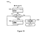
本願明細書においてたとえば図3〜図15に、複合物理の問題をセットアップし当該問題に解答するための方法および他のモデリングシステムが記載されており、さらに、2012年7月10日に発行された米国特許番号第8,219,373号と、2009年11月24日に発行された米国特許番号第7,623,991号と、2009年4月14日に発行された米国特許番号第7,519,518号と、2009年9月29日に発行された米国特許番号第7,596,474号と、2011年7月15日に出願された第13/184,207号である2012年7月12日に公開された米国特許出願公開番号第2012/0179426号とに記載され、その各々がここで、それらの全体において本願明細書に参照により援用される。これらの公開特許文献は、たとえば、物理量で表わされ得る物理的特性の形態にある入力を受け取ることで、いくつかの結合された物理的現象を含む複合物理シミュレーションをセットアップおよび実行するための方法を記載する。さらに、上記の参照された米国特許および特許出願は、偏微分方程式(partial differential equation(PDE))を使用して記述された物理的特性、物理量および物理的現象を使用して問題をセットアップするための方法を開示する。これらの公開された特許文献は、本願明細書において物理インターフェイスと称される予め規定されたアプリケーションモードを使用して、複合物理の問題をセットアップし当該問題に解答するための方法およびシステムを提供する。物理インターフェイスのコンポーネントは、パラメータ、変数、物理的特性、物理量、境界条件および初期条件、ならびにセッティングおよびメニューを有するソルバーを含み得る。これらのセッティングおよびメニューは、一般的な数学的セッティングを使用する代わりに、特定の物理に調節され得る。さらに、これらの公開された特許の開示はまた、予め規定された物理インターフェイスが利用可能でない場合に、PDEインターフェイスとも称されるPDEモードのための方法を記載する。複合物理の問題をセットアップするための一般的なPDEモードおよびPDEインターフェイスの使用は、PDEでの物理的特性、物理量および物理的現象の記述に関する知見を必要とする。 For example, FIGS. 3-15 herein describe a method and other modeling system for setting up and solving a complex physics problem, and was issued on July 10, 2012. U.S. Pat. No. 8,219,373, U.S. Pat. No. 7,623,991 issued on Nov. 24, 2009, and U.S. Pat. No. 7, issued on Apr. 14, 2009. No. 519,518, U.S. Pat. No. 7,596,474 issued September 29, 2009, and No. 13 / 184,207, filed Jul. 15, 2011. U.S. Patent Application Publication No. 2012/0179426, published on May 12, each of which is hereby incorporated by reference herein in its entirety. These published patent documents describe, for example, methods for setting up and executing complex physical simulations that include several coupled physical phenomena by receiving input in the form of physical properties that can be expressed in physical quantities. Is described. In addition, the above referenced US patents and patent applications can be used to set up problems using physical properties, physical quantities and physical phenomena described using partial differential equations (PDEs). The method is disclosed. These published patent documents provide methods and systems for setting up and solving complex physics problems using a predefined application mode, referred to herein as a physical interface. . The components of the physical interface may include solvers with parameters, variables, physical properties, physical quantities, boundary conditions and initial conditions, and settings and menus. These settings and menus can be adjusted to specific physics instead of using general mathematical settings. Furthermore, the disclosures of these published patents also describe a method for PDE mode, also referred to as PDE interface, when a predefined physical interface is not available. The use of common PDE modes and PDE interfaces to set up complex physics problems requires knowledge about the description of physical properties, physical quantities and physical phenomena in the PDE.
複合物理モデルに基づいてアプリケーションデータ構造を生成するよう動作可能または適合されるシステムおよび方法が望ましく、モデリングおよびシミューレーションシステムを含むエンジニアリング設計システムにさまざまな計算上の利点を提供するであろうということが考えられる。アプリケーションデータ構造を生成するための方法およびシステムは、複合物理モデルについてのフィーチャおよびフィーチャセッティングへのアクセスのために構成または適合されるアプリケーションビルダーモジュールにおいて専用のグラフィカルユーザインターフェイス上で実現され得る。このようなグラフィカルユーザインターフェイスは、既存のセッティングを複合物理モデルに使用するアプリケーションを示すデータ構造を生成するためのメソッドにもアクセスを提供し得る。アプリケーションデータ構造はさらに、シミュレーションの実行を可能にするようにアプリケーションモデルデータ構造および複合物理モデルデータ構造を生成するための複合物理モデリングシステムにおいてアプリケーションデータ構造をグラフィカルユーザインターフェイスからアクセス可能にする別のシステムまたは方法を介して解釈(たとえば実行)され得る。 Systems and methods that are operable or adapted to generate application data structures based on complex physical models are desirable and will provide various computational advantages to engineering design systems, including modeling and simulation systems It is possible. The methods and systems for generating application data structures may be implemented on a dedicated graphical user interface in an application builder module that is configured or adapted for access to features and feature settings for a composite physical model. Such a graphical user interface may also provide access to methods for generating a data structure representing an application that uses existing settings for the composite physical model. The application data structure is further a separate system that makes the application data structure accessible from a graphical user interface in a composite physical modeling system for generating the application model data structure and the composite physical model data structure to enable execution of a simulation. Or it can be interpreted (eg, performed) via a method.
この開示の全体にわたって、グラフィカルユーザインターフェイスを介してアクセス可能な処理部上で実行されるメソッドを含むシステムのさまざまな非限定的な例示的な局面が本願明細書において記載される。当該メソッドは、アプリケーションデータ構造、アプリケーションモデルデータ構造、および物理システムをモデリングするための他のタイプのデータ構造を生成するための命令を含む。生成されたデータ構造は、データ構造がシステムのユーザによって構築および適用され得るエンジニアリング解析システム(たとえば複合物理モデリングシステム)に適用され得るかまたは関連付けられ得るということが考えられる。 Throughout this disclosure, various non-limiting exemplary aspects of a system that includes methods executed on a processor accessible via a graphical user interface are described herein. The methods include instructions for generating application data structures, application model data structures, and other types of data structures for modeling physical systems. It is contemplated that the generated data structure can be applied or associated with an engineering analysis system (eg, a complex physical modeling system) where the data structure can be constructed and applied by a user of the system.
複合物理モデリングシステムの例示的な局面において、物理量において物理的特性の形態にある入力を受け取る第1のインタプリタモジュールが提供され得、その後、モデルオブジェクト(たとえばモデルデータ構造)を生成する。モデルオブジェクトは、モデルについてのアルゴリズムおよびデータ構造を含み得、さらに当該モデルを表わすよう使用され得る。モデルオブジェクトはさらに、モデルについて形状、メッシュおよび解を作成するよう、動作のシーケンスをセットアップおよび実行するメソッドを含み得る。 In an exemplary aspect of a complex physical modeling system, a first interpreter module may be provided that receives input in the form of physical properties in physical quantities, and then generates a model object (eg, a model data structure). A model object may contain algorithms and data structures for the model and may be used to represent the model. The model object may further include methods for setting up and executing a sequence of operations to create shapes, meshes and solutions for the model.
エンジニアリング解析システムを実施する物理的なコンピューティングデバイスは、システムのユーザがシミュレーションを入力および実行し、アプリケーションデータ構造を構築することを可能にする1つ以上のグラフィカルユーザインターフェイスを有するように構成され得る。コンピュータシステムは、上に記載された非限定的な例示的なルーチンまたはメソッドのうちのいくつかを含み得、さらに異なるタイプのシミュレーションのための異なるインターフェイスを含み得る。たとえば、流量シミュレーション、伝熱シミュレーション、電磁気シミュレーション、および/または構造力学シミュレーションのために異なるユーザインターフェイスが提供され得る。他のエンジニアリングまたは物理現象のためのシミュレーションおよび関連するインターフェイスもコンピュータ支援エンジニアリング解析システムについて考慮される。 A physical computing device that implements an engineering analysis system may be configured to have one or more graphical user interfaces that allow a user of the system to enter and run simulations and build application data structures. . The computer system may include some of the non-limiting exemplary routines or methods described above, and may include different interfaces for different types of simulations. For example, different user interfaces may be provided for flow simulation, heat transfer simulation, electromagnetic simulation, and / or structural mechanics simulation. Simulations and related interfaces for other engineering or physical phenomena are also considered for computer-aided engineering analysis systems.
アプリケーションデータ構造およびアプリケーションモデルデータ構造を生成または構築するための専用のグラフィカルユーザインターフェイスを有するシステムは、本開示のいくつかの局面において考慮される。たとえば、コンピュータシステムは、所望の解析またはシミュレーションに関連付けられる所望の物理的現象についてのパラメータ、フォーム、フィーチャ、アクション、変数、物理的特性、物理量および/または物理インターフェイスフィーチャを規定するためのグラフィカルユーザインターフェイスを含み得る。グラフィカルユーザインターフェイスは、アプリケーションデータ構造を生成するルーチンまたはメソッドへのアクセスを可能にし得る。その後、生成されたデータ構造は、アプリケーションモデルデータ構造を作成するように構成され、かつ、たとえば複合物理モデリングシステムのようなエンジニアリング解析システムに関連付けられる他のグラフィカルユーザインターフェイスからアプリケーションインターフェイスがアクセス可能になるようにするように構成されるルーチンまたはメソッドによって解釈または実行され得る。これらの動作のためのルーチンまたはメソッドが、エンジニアリング解析システムを実行する1つ以上の処理部上でローカルにおよび/または当該処理部へのネットワーク接続を介してリモートに実行され得るということが考えられる。 A system having a dedicated graphical user interface for generating or building application data structures and application model data structures is contemplated in some aspects of the present disclosure. For example, a computer system may include a graphical user interface for defining parameters, forms, features, actions, variables, physical properties, physical quantities, and / or physical interface features for a desired physical phenomenon associated with a desired analysis or simulation. Can be included. The graphical user interface may allow access to routines or methods that generate application data structures. The generated data structure is then configured to create an application model data structure and the application interface is accessible from other graphical user interfaces associated with an engineering analysis system such as a complex physical modeling system. Can be interpreted or executed by a routine or method that is configured to do so. It is contemplated that routines or methods for these operations may be executed locally on one or more processing units executing an engineering analysis system and / or remotely via a network connection to the processing unit. .
コンピュータシステムは、本開示に記載される異なるタスクを行なうために使用され得る。コンピュータシステムを使用するための1つの局面は、コンピュータ読取可能媒体(たとえば、一時的または固定的なメモリ、磁気ストレージ、光学ストレージ、電子ストレージ、フラッシュメモリ、他の記憶媒体)上に格納されたエンジニアリング解析システムおよびメソッドを含む1つ以上のコンピュータプログラムを実行することを含む。コンピュータプログラムは、プロセッサによって実行されると1つ以上のタスクを行なう命令を含み得る。ある実施形態において、コンピュータシステムは、モデリングおよびシミュレーションならびに/または問題解答タスクを行なうように、たとえばマシンが実行可能なコードへのソースコードの変換に関連して、生成され得るマシン命令を実行する。物理的現象または物理的なプロセスをモデリングおよびシミュレートするために使用され得る1つの技術は、変数および方程式でまたはコンピュータシステムによって処理され得る他の定量可能な形態で、モデリングおよびシミュレートされる物理的現象または物理的なプロセスのさまざまな物理的特性および物理量を表わすことである。翻って、これらの方程式または他の定量可能な形態は、方程式に関連付けられる1つ以上の変数について解答するように構成されるコンピュータシステムによって解答され得るか、または、当該コンピュータは、他の受け取った入力パラメータを使用して問題に解答するように構成され得る。 A computer system may be used to perform the different tasks described in this disclosure. One aspect for using computer systems is engineering stored on computer-readable media (eg, temporary or permanent memory, magnetic storage, optical storage, electronic storage, flash memory, other storage media). Including executing one or more computer programs including an analysis system and methods. A computer program may include instructions that, when executed by a processor, perform one or more tasks. In certain embodiments, the computer system executes machine instructions that may be generated, eg, in connection with converting source code to machine executable code, to perform modeling and simulation and / or problem solving tasks. One technique that can be used to model and simulate physical phenomena or processes is physics modeled and simulated in variables and equations or in other quantifiable forms that can be processed by a computer system. To represent various physical properties and quantities of a physical phenomenon or physical process. In turn, these equations or other quantifiable forms may be solved by a computer system configured to answer for one or more variables associated with the equations, or the computer may receive other It can be configured to answer the question using the input parameters.
物理的現象または物理的プロセスをモデリングおよびシミュレートするためのコンピュータプログラムは、特にモデリングおよびシミュレートされる物理的現象または物理的なプロセスの複雑さが増加する際に、多くの利点を提供し得るということが考えられる。たとえば、ある実施形態において、ユーザは、たとえばエンジニアリング解析の部分として、1つ以上の物理的現象を複合物理モデルに組み合わせ得る。さらにこの例を示すために、ユーザは、化学反応速度論および流体力学、電磁気現象および伝熱、構造力学および流量、または他の物理現象によって記述される現象を組み合わせ得る。このような複合物理モデルはさらに、複数の物理的なプロセスを含み得る。たとえば、アンプおよびアクチュエータの両方が1つの複合物理モデルの部分であり、アンプがアクチュエータに電力を供給することを含むプロセスが組み合わせられ得る。複合物理モデリングはさらに、偏微分方程式(PDE)の結合系を解くことを含み得る。 A computer program for modeling and simulating a physical phenomenon or physical process can provide many advantages, especially as the complexity of the physical phenomenon or physical process being modeled and simulated increases It can be considered. For example, in certain embodiments, a user may combine one or more physical phenomena into a composite physical model, for example as part of an engineering analysis. To further illustrate this example, the user may combine phenomena described by chemical kinetics and fluid dynamics, electromagnetic phenomena and heat transfer, structural mechanics and flow, or other physical phenomena. Such a complex physical model may further include multiple physical processes. For example, both an amplifier and an actuator can be part of one complex physical model, and processes involving the amplifier supplying power to the actuator can be combined. Complex physical modeling can further include solving a coupled system of partial differential equations (PDEs).
本願明細書において記載されるモデリングシステムのようなモデリングシステムが動作するコンピュータシステムは、ネットワーク化されたコンピュータまたはプロセッサを含み得るということが考えられる。ある実施形態では、プロセッサはモデリングシステムのユーザのコンピュータ上で直接的に動作し得、他の実施形態では、プロセッサはリモートに動作し得る。たとえば、ユーザは、ある位置にある1つのコンピュータまたは端末にてさまざまな入力パラメータを提供し得る。それらのパラメータは、1つのコンピュータ上でローカルに処理され得るか、または、当該パラメータは、ローカルエリアネットワークまたはワイドエリアネットワークを介して、入力パラメータを処理するように構成されるネットワーク上のどこか他のところに位置する別のプロセッサに転送され得る。第2のプロセッサは、インターネット(もしくは他のネットワーク)に接続されたサーバに関連付けられ得るか、または、第2のプロセッサは、インターネット(もしくは他のネットワーク)に接続された、各々がモデリングシステム上の問題を展開および解決するための選択関数を扱ういくつかのプロセッサであり得る。1つ以上のプロセッサによる処理の結果が、その後、さらに別のサーバまたはプロセッサで収集され得るということがさらに考えられる。さらに、上記結果は、ユーザが位置している端末またはコンピュータに戻って収集され得るということが考えられる。ユーザが位置している端末またはコンピュータは次いで、表示(たとえば一時的な表示)を介してまたは(たとえばプリンタを介する)ハードコピーの形態でユーザに複合物理モデリングシステムの解を表示し得る。代替的または付加的には、上記解は、端末またはコンピュータに関連付けられるメモリに格納され得るか、または、当該解は、モデリングシステムから解を得るようユーザがアクセスし得る別のサーバ上に格納され得る。 It is contemplated that a computer system in which a modeling system, such as the modeling system described herein, can operate includes a networked computer or processor. In some embodiments, the processor may operate directly on the computer of the modeling system user, and in other embodiments, the processor may operate remotely. For example, a user may provide various input parameters at one computer or terminal at a location. The parameters can be processed locally on one computer, or the parameters can be somewhere else on the network that is configured to process input parameters via a local area network or a wide area network. Can be forwarded to another processor located at. The second processor may be associated with a server connected to the Internet (or other network), or the second processor is connected to the Internet (or other network), each on the modeling system There may be several processors that handle selection functions for developing and solving problems. It is further contemplated that the results of processing by one or more processors can then be collected at yet another server or processor. Further, it is conceivable that the results can be collected back to the terminal or computer where the user is located. The terminal or computer in which the user is located may then display the complex physical modeling system solution to the user via a display (eg, a temporary display) or in the form of a hard copy (eg, via a printer). Alternatively or additionally, the solution may be stored in a memory associated with the terminal or computer, or the solution is stored on another server that the user can access to obtain the solution from the modeling system. obtain.
ある実施形態において、製品またはプロセスは、設計または分析される開発ステージまたはフィージビリティステージにあり得るということが考えられる。開発または分析される製品またはプロセスは、いくつかの物理的特性および物理量を含む複雑な環境における使用のために評価される必要があり得る。コンピュータベースの設計システムにおいて、システム的にパラメータフィーチャおよび形状フィーチャを変動することにより、複雑な複合物理問題を解くことが望ましくあり得る。他の望ましいフィーチャは、たとえば、メモリに位置し、かつ、複合物理モデルを形成しおよび/または複合物理問題を解決するために使用される物理的特性および境界条件のためのセッティングが設計システムから直接的にアクセスされ得る複雑な複合物理問題を解くためのコンピュータベースのシステムを有することを含み得る。 In certain embodiments, it is contemplated that a product or process may be in a development or feasibility stage that is designed or analyzed. A product or process to be developed or analyzed may need to be evaluated for use in a complex environment that includes several physical properties and quantities. In computer-based design systems, it may be desirable to solve complex complex physics problems by systematically varying parameter and shape features. Other desirable features are located directly in the design system, for example, physical properties and boundary conditions located in memory and used to form a complex physical model and / or solve complex physical problems Having a computer-based system for solving complex complex physics problems that can be accessed automatically.
ここで図1を参照して、モデリングシステムとアプリケーションデータ構造を生成するためのシステムとを含む、本願明細書において別記される方法とともに使用され得るコンピュータシステムの例示的な局面が示される。コンピュータシステム110は、通信媒体118を通じてホストシステム114a−114nに接続されたデータストレージシステム112を含む。コンピュータシステム110のこの実施形態において、たとえば、「n個」のホスト114a−114nが、入力/出力(I/O)動作を行なう際に、データストレージシステム112にアクセスし得る。通信媒体118は、モデリングおよびコンピュータシミュレーション分野において公知のように、さまざまなネットワークまたは他のタイプの通信接続のいずれか1つであり得る。たとえば、通信媒体118は、ホストシステム114a−114nがアクセスし得、データストレージシステム112と通信し得るインターネット、イントラネットまたは他のネットワーク接続であり得、ネットワーク通信(たとえばファイバーオプティック、無線、イーサーネット(登録商標))のさまざまな形態に基づいたシステムを含むがこれに限定されない、コンピュータシステム110に含まれる他のものと通信し得る。
With reference now to FIG. 1, there are shown exemplary aspects of a computer system that can be used with methods described elsewhere herein, including a modeling system and a system for generating application data structures.
ホストシステム114a−114nの各々およびコンピュータシステム110に含まれるデータストレージシステム112は、通信媒体118のタイプに従って提供およびサポートされ得るようなさまざまな接続のうちのいずれか1つによって、通信媒体118に接続され得る。ホストコンピュータシステム114a−114nまたはデータマネージャシステムに含まれるプロセッサは、各特定の実施形態およびアプリケーションに従って入力トラフィックをサポートすることが可能であるインテルベースのプロセッサ、IBMメインフレーム、サーバまたは他のタイプの商業的に利用可能なプロセッサといったさまざまな商業的に利用可能なシングルプロセッサシステムまたはマルチプロセッサシステムのうちのいずれか1つであり得る。
Each of the
なお、ホストシステム114a−114nの各々に含まれるハードウェアおよびシステムの詳細と、データストレージシステム112に含まれ得るコンポーネントとは、本願明細書においてより詳細に記載され、各特定の実施形態に応じて変化し得る。ホストコンピュータ114a−114nの各々およびデータストレージシステム112は、すべて同じ物理的な位置に位置してもよく、または代替的には、異なる物理的位置に位置してもよい。ホストコンピュータシステム、データマネージャシステム、およびコンピュータシステム110のデータストレージシステムの間の異なるタイプの接続を提供するために使用され得る通信媒体の例は、コンピュータモデリングおよびシミュレーション分野の当業者に公知であるSCSI、ESCON、ファイバーチャンネル(Fiber Channel)または機能的な同等物のようなさまざまな異なる通信プロトコルを使用し得る。ホストおよびデータストレージシステム112が通信媒体118に接続され得る接続のうちのいくつかまたはすべては、電話線、中継器、マルチプレクサまたはサテライトといった物理的および仮想的の両方で存在し得るコネクトリクス(Connectrix)または他のスイッチ機器のような他の通信装置を通過し得る。
The details of the hardware and system included in each of the
ホストコンピュータシステムの各々は、ホストコンピュータシステムの1つ以上の上で実行するアプリケーションに関連して使用されるデータファイルを格納および抽出するといった異なるタイプのデータ動作を行ない得る。たとえば、コンピュータプログラムは、ホストコンピュータ114aの上で実行し得、データを格納およびデータストレージシステム112から抽出し得る。データストレージシステム112は、各実現例に従った、ディスクおよびテープなどといった任意数のさまざまな異なるデータストレージデバイスを含み得る。以下の段落に記載されるように、方法は、ホストコンピュータシステム114a−114nのうちのいずれか1つ上に存在および実行され得る。データは、方法を実行するホストシステム上でローカルに格納され得るとともに、データストレージシステム112においてまたは別のホストコンピュータシステム上にリモートで格納され得る。同様に、各コンピュータシステム110の構成に依存して、本願明細書において記載されるような方法は、ホストコンピュータシステムのうちの1つ上に格納および実行され得、ローカルデータを使用して別のコンピュータシステム上のユーザによってリモートにアクセスされ得る。図1のコンピュータシステム110の実施形態に関連して記載されるように、さまざまな異なるシステム構成および変更が可能であり、本願明細書において別記される技術の限定として解釈されるべきでない。
Each of the host computer systems may perform different types of data operations, such as storing and extracting data files used in connection with applications executing on one or more of the host computer systems. For example, a computer program may execute on the
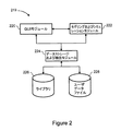
ここで図2を参照して、たとえば単一のコンピュータ上または複数のホストコンピュータシステム(たとえばホストコンピュータ114a−114n)のうちの1つにおいて存在し得るモデリングシステム219の例示的な局面が示される。モデリングシステムは、いくつかのコンポーネントに分割され得る。当該システムの例示的な1つの局面は、GUIモジュール220と、モデリングおよびシミュレーションモジュール222と、データストレージおよび抽出モジュール224とを含み得る。GUIモジュール220は、システムのユーザとの対話を提供し得る。モデリングおよびシミュレーションモジュール222は、複合物理シミュレーションを管理および実行する能力を提供し得る。データストレージおよび抽出モジュール224は、ファイル中のモデルをロードおよび保存するとともに、シミュレーションの間に使用され得るかまたはシミュレーションに対する入力または出力として使用され得る他のタイプのファイルをロードおよび保存する能力を提供し得る。
Referring now to FIG. 2, an exemplary aspect of a
GUIモジュール220は、コマンドを送信および受信することにより、モデリングおよびシミュレーションモジュール222と通信し得る。コマンドを送信および受信する動作は、アプリケーションプログラミングインターフェイス(「API」)または他の同様のコンポーネントを通じて行なわれ得る。システムの1つの局面において、APIはオブジェクト指向であり得、同じ構造内でデータおよび関数呼出を混合し得る。システムの別の局面において、APIは、関数呼出とは別個のデータ構造を使用し得る。
The
本開示のある局面において、複合物理モデリングシステムのコンポーネントは異なるホストコンピュータシステム上に存在し得るということが考えられる。たとえば、GUIモジュール220はパーソナルコンピュータホスト上に存在し得、モデリングおよびシミュレーションモジュール222はサーバコンピュータホスト上に存在し得る。さらに、データストレージおよび抽出モジュール224は、パーソナルコンピュータホスト、サーバコンピュータホストまたはさらに別の別個のコンピュータホストのいずれかの上に存在し得るということが考えられる。コンピュータホストが同一でない場合、APIは、ホスト間で通信するためにコンピュータネットワークを使用するように構成され得る。オブジェクト指向のAPIは、一実施形態では、コンピュータネットワークを介して、データおよびメソッド呼出を送信するよう構成され得、または、別の実施形態では、コンピュータネットワークを介してコンポーネント間でデータおよび関数呼出を送信するよう構成され得る。APIはさらに、GUIモジュール220またはモデリングおよびシミュレーションモジュール222のホスト上または別個のホスト上に位置し得るデータストレージおよび抽出モジュール224を扱うことが可能であり得る。それらの場合の各々において、データストレージおよび抽出モジュール224は、それらのホストの各々上のファイルをロードおよび格納するように構成され得る。
In certain aspects of the present disclosure, it is contemplated that components of a complex physical modeling system may reside on different host computer systems. For example, the
ある局面において、システム219は、Windows(登録商標) 8、Mac OS、iOS、AndroidおよびChrome OSなどといったオペレーティングシステム、または、図2に示されるモデリングシステム219に記載および表わされるもの以外のシステムコンポーネントを含み得るまたは有するよう構成され得るということが考えられる。図2に示される例示的な局面において、ライブラリ226およびユーザデータファイル228は、ホストコンピュータシステム内にローカルに格納され得る。ある局面において、ライブラリ226および/またはユーザデータファイル228と、これらのコピーとは、別のホストコンピュータシステムおよび/またはコンピュータシステム110のデータストレージシステム112に格納され得るということがさらに考えられる。しかしながら、以下の段落における簡潔さおよび説明のために、システム219は、たとえばデータストレージシステム112におけるユーザデータファイルおよびライブラリの付加的なバックアップとともに、114aのような単一のホストコンピュータシステム上に存在し得るということを非限定的な態様で仮定する。
In one aspect, the
本開示のある局面において、GUIモジュール220、モデリングおよびシミュレーションモジュール222、データストレージおよび抽出モジュール224、ならびに/またはライブラリ226といったモデリングシステム219の部分は、商業的に利用可能なシステムパッケージと組み合わされて含まれるかまたは実行され得る。これらのコンポーネントは、ホストシステム114a−114nのうちの1つの上で動作し得、Windows XP(登録商標)、Windows 7、Windows 8、Windows HPCサーバ2008 R2、Unix(登録商標)、Linux(登録商標)、Mac OS(登録商標)、iOS、Chrome(登録商標)OSおよびAndroid(登録商標)などといった1つ以上のオペレーティングシステムを含み得る。モデリングシステム219のモジュールは、C、C++、C#、Java(登録商標)もしくはその任意の組合せまたは他の商業的に利用可能なプログラミング言語といったさまざまなコンピュータプログラミング言語のうちのいずれか1つで書かれてもよいということがさらに考えられる。
In certain aspects of the present disclosure, portions of the
GUIモジュール220は、システムのユーザによる考慮下で、1つ以上のプロセスおよび/または物理的現象についてモデリング、シミュレーションおよび/または他の問題解答を行うために用いるデータを取得することに関連してGUIウィンドウを表示し得るということが考えられる。1つ以上のプロセスおよび/または現象は、モデリングおよびシミュレーションモジュール222によって集められ解答され得る。すなわち、ユーザデータは、GUIモジュール220のようなモジュールを使用してシステムによって収集または受信され得、その後、モデリングおよびシミュレーションモジュール222によって使用され得る。その後、データはデータストレージおよび抽出モジュール224に移動または転送され得、データストレージおよび抽出モジュール224において、ユーザが入力したデータが別個のデータ構造に格納され得る(たとえばユーザデータファイル228)。他のデータおよび情報が、モデリングおよびシミュレーションモジュール222によってまたはGUIモジュール220に関連して使用され得るライブラリ226のような別個のデータ構造に格納および当該データ構造から抽出され得るということが考えられる。
The
ユーザデータファイル228およびライブラリ226のようなモデリングシステムに関連付けられ得るさまざまなデータファイルは、ホストコンピュータシステムまたはデータストレージシステム112において使用されるファイルシステムに関連して、さまざまなデータファイルフォーマットのうちのいずれか1つに格納され得る。ある局面において、システム219は、データの格納および抽出に関連してさまざまなデータベースパッケージのうちのいずれか1つを使用し得る。ユーザデータファイル228はさらに、他のシミュレーションおよびモデリングシステムに関連して使用され得る。たとえば、ユーザデータファイル228は、さまざまな他のモデリングシステムのうちのいずれか1つへの入力として直接的または間接的に使用され得るフォーマットで格納され得る。ある局面において、データは、複合物理モデリングシステムと別のシステムとの間でインポートおよび/またはエクスポートされ得る。データのフォーマットは、システムの各々に従って、かつ、システムの各々が含み得る付加的な機能性に従って変更またはカスタマイズされ得る。
Various data files that may be associated with a modeling system such as user data file 228 and
本願明細書において記載されるシステムおよび方法は、異なる物理的現象またはプロセスをモデリングする物理インターフェイスを組み合わせるために用いられ得るということが考えられる。複数の物理インターフェイスの組合せは、複合物理モデルとも称され得る。物理インターフェイスの特性は、結合系または結合表示において物理量を記述するPDEを形成するよう自動的に組み合わされ得るPDEによって表わされ得る。結合されたPDEはたとえば、結合されたPDEが修正されてソルバーへの入力として使用されることを可能にする「方程式ビュー」で表示され得る。さらに、PDEは、単一の現象もしくはプロセスを記述する1つのPDEまたはPDEの系として独立してか、または、いくつかの現象もしくはプロセスを記述する1つのPDEもしくはいくつかのPDEの系としてソルバーに提供され得るということが考えられる。 It is contemplated that the systems and methods described herein can be used to combine physical interfaces that model different physical phenomena or processes. A combination of multiple physical interfaces may also be referred to as a complex physical model. The properties of a physical interface can be represented by a PDE that can be automatically combined to form a PDE that describes a physical quantity in a coupled system or coupled display. The combined PDE may be displayed, for example, in an “equation view” that allows the combined PDE to be modified and used as an input to the solver. In addition, a PDE can be solved as a single PDE or system of PDEs describing a single phenomenon or process, or as a single PDE or system of several PDEs describing several phenomena or processes. It can be considered that it can be provided.
本開示のある局面において、複合物理モデリングシステムは、ユーザがリストから1つ以上の物理インターフェイスを選択することを可能にする1つ以上のGUIを通じて物理的特性をモデリングする物理インターフェイスを組み合わせる能力を提供し得る。物理インターフェイスの名称の表示に加えて、さらに、物理量についての変数名称がGUIを介して選択され得ることが考えられる。物理インターフェイスは、より詳細に本願明細書において別記される「検討(study)」セッティングフィーチャに依存する異なる定式化を有し得るということが考えられる。 In certain aspects of the present disclosure, a complex physical modeling system provides the ability to combine physical interfaces that model physical properties through one or more GUIs that allow a user to select one or more physical interfaces from a list. Can do. In addition to displaying the name of the physical interface, it is further conceivable that a variable name for the physical quantity can be selected via the GUI. It is contemplated that a physical interface may have different formulations that depend on “study” setting features, which are described in more detail elsewhere herein.
さらに、複合物理モデリングシステムが、複合物理モデルを規定するためのいくつかの物理的現象の予め規定された組合せにアクセスする能力を提供することは望ましくあり得るということが考えられる。当該予め規定された組合せは、物理インターフェイスと同様に、検討セッティングフィーチャに依存する異なる定式化を有し得る複合物理インターフェイスと称され得る。 It is further contemplated that it may be desirable for a complex physical modeling system to provide the ability to access a predefined combination of several physical phenomena for defining a complex physical model. The predefined combination may be referred to as a composite physical interface that may have different formulations depending on the study setting feature, as well as the physical interface.
本開示のある局面において、物理的特性は、モデリングシステムを使用して検討されるコンポーネントおよび/またはプロセスについての物理量をモデリングするために使用され得、物理的特性は、物理的特性が数値として記述されることを可能にするGUIを使用して規定され得るということが考えられる。ある局面において、物理的性質はさらに、1つ以上の数値、空間座標、時間座標および/または実際の物理量を含む数式として規定され得る。ある局面において、物理的特性は、形状ドメインのいくつかの部分に該当し得、物理量自身は、形状ドメインの他の部分において未定義であり得る。形状ドメインまたは「ドメイン」は、分離したサブドメインに分割され得る。これらのサブドメインの数学的な結合が、形状ドメインまたは「ドメイン」を形成する。ドメインの完全な境界はさらに、「境界」と称されるセクションに分割され得る。隣接するサブドメインは、「ボーダー」と称される共通の境界を有し得る。完全な境界はたとえば、サブドメインボーダーを含むすべての境界の数学的な結合である。たとえばある局面において、形状ドメインは、GUIにおいて一次元、二次元、または三次元であり得る。しかしながら、より詳細に本願明細書において別記されるように、ソルバーは任意の空間次元を扱うことが可能であり得る。1つの実現例におけるGUIの使用を通じて、ドメインの境界上の物理的特性は、PDEの境界条件を導出するよう特定および使用され得るということが考えられる。 In certain aspects of the present disclosure, physical properties may be used to model physical quantities for components and / or processes that are considered using a modeling system, where physical properties are described as physical properties as numerical values. It is conceivable that it can be defined using a GUI that allows it to be done. In certain aspects, the physical property may be further defined as a mathematical formula that includes one or more numerical values, spatial coordinates, temporal coordinates, and / or actual physical quantities. In one aspect, the physical property can fall into some part of the shape domain, and the physical quantity itself can be undefined in other parts of the shape domain. A shape domain or “domain” may be divided into separate subdomains. The mathematical combination of these subdomains forms a shape domain or “domain”. The complete boundaries of a domain can be further divided into sections called “boundaries”. Adjacent subdomains may have a common boundary called a “border”. A complete boundary is, for example, a mathematical combination of all boundaries, including subdomain borders. For example, in certain aspects, the shape domain may be one-dimensional, two-dimensional, or three-dimensional in the GUI. However, the solver may be able to handle any spatial dimension, as detailed elsewhere herein. It is contemplated that through the use of the GUI in one implementation, the physical characteristics on the domain boundaries can be identified and used to derive the PDE boundary conditions.
モデリングおよびシミュレーションモジュール222において発見され得るフィーチャのようなモデリングシステムの付加的なフィーチャは、PDEの系と複合物理モデルについての境界条件とを自動的に導出することを提供し得る。この技術は、複数の現象またはプロセスのPDEをマージすることを含み得、異なる座標系においてプロセスを結合するよう、結合変数または演算子を使用して、結合したPDEの単一の系を作り出し得、ソルバーによるその後の使用についてすべての従属変数に関してPDEの系の記号微分を行ない得る。
Additional features of the modeling system, such as those that can be found in the modeling and
ある局面において、PDEの結合系は、微分されてソルバーに送られる前に、修正され得るということが考えられる。この修正は、「方程式ビュー」における結合されたPDEを表示するGUIに含まれるセッティングウィンドウを使用して行なわれ得る。PDEの系がこのように修正される場合、対応する物理的特性についてのセッティングは「ロック状態」になり得る。当該特性はその後、ユーザがあるアクションを行うことによってロック解除され得る。 In one aspect, it is conceivable that the coupled system of PDEs can be modified before being differentiated and sent to the solver. This modification can be done using a settings window included in the GUI that displays the combined PDEs in the “Equation View”. If the PDE system is modified in this way, the setting for the corresponding physical property can be "locked". The property can then be unlocked by the user performing an action.
本開示のある局面は、たとえば音響、化学反応、拡散、電磁気、流体力学、地球物理学、伝熱、光学、プラズマ物理学、量子力学、半導体物理学、構造力学および波の伝播などを含む複数のエンジニアリングおよび科学的教義の1つ以上のモデリングのためのフィーチャを含み得るということが考えられる。モデリングシステムのある局面は、上記の教義のうちの1つより多くを含み得、さらに、前述の教義の組合せを表わすまたはモデリングすることを含み得る。更に、本願明細書において記載される技術は、PDEの1つ以上の系に関連して使用され得る。 Certain aspects of the present disclosure include multiples including, for example, acoustics, chemical reactions, diffusion, electromagnetics, fluid dynamics, geophysics, heat transfer, optics, plasma physics, quantum mechanics, semiconductor physics, structural mechanics, wave propagation, and the like. It is contemplated that one or more features for modeling one or more engineering and scientific doctrines may be included. Certain aspects of the modeling system may include more than one of the above doctrines and may further include representing or modeling a combination of the above doctrines. Further, the techniques described herein can be used in connection with one or more systems of PDEs.
本開示のある局面において、PDEの系は、一般形式、係数形式および/または弱形式で表わされ得るということが考えられる。係数形式は、線形またはほぼ線形の問題に関連してより好適であり得る一方、一般形式および弱形式は、非線形の問題に関連する使用により好適であり得る。モデリングされるシステムは、たとえば、定常的で時間依存の固有値または固有周波数のように1つ以上の関連する検討を有し得る。本願明細書において記載される局面において、有限要素法(finite element method(FEM))は、たとえば、アダプティブメッシング、アダプティブタイムステッピング、および/または1つ以上の異なる数値ソルバーの選択とともに、PDEについて解くよう使用され得る。 In certain aspects of the present disclosure, it is contemplated that a PDE system may be represented in general form, coefficient form, and / or weak form. The coefficient form may be more suitable in connection with linear or near linear problems, while the general form and weak form may be more suitable for use in connection with non-linear problems. The modeled system may have one or more related considerations such as, for example, stationary, time-dependent eigenvalues or natural frequencies. In aspects described herein, a finite element method (FEM) may be solved for a PDE, eg, with adaptive meshing, adaptive time stepping, and / or selection of one or more different numerical solvers. Can be used.
本開示のある局面において、有限要素メッシュは、形状ドメインの表示を形成するシンプレックスを含み得るということが考えられる。各シンプレックスは、一意のサブドメインに属し得、シンプレックスの結合は形状ドメインの近似を形成し得る。ドメインの境界はさらに、それぞれ形状的な次元である1、2および3に対して次元0、1および2のシンプレックスによって表わされ得る。
It is contemplated that in certain aspects of the present disclosure, a finite element mesh may include a simplex that forms a representation of a shape domain. Each simplex can belong to a unique subdomain, and the association of simplexes can form an approximation of the shape domain. Domain boundaries can be further represented by simplexes of
さらに、形状を表わすメッシュも、外側のまたは外部のアプリケーションによって作成され得、その後、本開示に記載されるモデリングシステムへの使用のためにインポートされ得るということが考えられる。 Further, it is contemplated that the mesh representing the shape can also be created by an external or external application and then imported for use in the modeling system described in this disclosure.
解答プロセスの初期値は、数値、空間座標、時間座標および実際の物理量を含み得る数値または式として与えられ得る。初期値はさらに、以前に決定された物理量を含み得る。 The initial value of the answering process can be given as a numerical value or expression that can include numerical values, spatial coordinates, temporal coordinates and actual physical quantities. The initial value may further include a previously determined physical quantity.
PDEの解は、物理的特性およびそれらの関連する量の任意のサブセットについて求められ得る。さらに、解かれなかった任意のサブセットは、PDEの系に対する初期値として扱われ得る。 PDE solutions can be determined for any subset of physical properties and their associated quantities. Furthermore, any subset that has not been solved can be treated as an initial value for the PDE system.
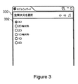
モデルウィザードを使用する複合物理モデリングシステムにおける空間次元、物理の組合せ、および検討のタイプをユーザが選択することが望ましくあり得るということが考えられる。モデルウィザードは、これらの選択ステップにユーザを案内し得、複合物理モデルにおけるいくつかの空間次元、いくつかの物理およびいくつかの検討または検討ステップの組合せを可能にし得る。 It is possible that it may be desirable for the user to select the spatial dimension, the combination of physics, and the type of consideration in a complex physical modeling system that uses a model wizard. The model wizard may guide the user through these selection steps and may allow a combination of several spatial dimensions, several physics and several examination or examination steps in a composite physical model.
ここで図3を参照して、複合物理モデルの空間次元332を特定するよう使用され得るユーザインターフェイスまたはGUI330の例示的な局面が示される。モデルは、0次元(空間独立,時間依存のみ)、1次元、1次元軸対称、2次元、2次元軸対称および3次元を含む空間次元の座標系において特定され得る。さらに、複数の部分またはスケールを含む現象またはプロセスを記述するために、ユーザが上記の座標系のいくつかを含むモデルを組み合わせ得るということが考えられる。
Referring now to FIG. 3, an exemplary aspect of a user interface or
ここで図4を参照して、1つより多い現象またはプロセス(たとえば音響、流体、電磁気、伝熱、構造力学)の組合せを有する複合物理モデルを特定するよう使用され得るユーザインターフェイスまたはGUI439の例示的な局面が示される。組み合わせられるべき各現象またはプロセスは物理インターフェイスに対応し得るということが考えられる。GUI439の使用を通じて、この組み合わされた複合物理モデルにおいて使用されるべき物理インターフェイスが特定され得る。各物理インターフェイスは、PDEで物理量をモデリングするように構成され得る。物理量は、PDEでの従属変数として直接的に示されるか、または、従属変数と物理量を表わす変数との間の関係によって示されるかのいずれかであり得る。この例示的な局面におけるPDEは一般に、GUIの使用を通じてユーザから「隠され」得る(たとえば直接的に見ることができない)。以前に論じたように、いくつかの物理インターフェイスがひとたび単一のモデルまたはモデルの系に組み合わせられると、当該モデルは複合物理モデルと称され得る。
Referring now to FIG. 4, an illustration of a user interface or
GUI439はさらに、ユーザの空間次元の選択に従ってユーザが選択し得る物理インターフェイス440の例示的なリスト(たとえばAC/DC、音響、化学種輸送、電気化学、流体、伝熱、プラズマ、高周波、構造力学)を含む。複合物理モデルに物理インターフェイスを加えるために、ユーザはリストから物理インターフェイスを選択し、これらの物理インターフェイスが複合物理モデルに含まれるべきであることを特定し得る。たとえば、ユーザは右クリックし、次いで、複合物理モデルに物理インターフェイス(たとえば流体における伝熱)を加えるために「選択されたものを追加」というコンテキストメニューアイテム442を選択し得る。選択の後、この物理インターフェイスは、GUI439における物理リストの下に「選択された物理」444のリストに加えられる。物理インターフェイスはさらに、「選択されたものを除去」ボタン446を選択することにより、リストから除去され得る。
The
複合物理モデルにおける各物理インターフェイスには、複合物理モデルにおける変数の源を識別するよう使用され得る一意な名称が与えられる。「選択された物理」リスト446に物理インターフェイスを加えた後、ユーザは、解かれる物理量を表わす従属変数の名称を編集し得る。たとえば、GUI439の「従属変数」セクション448における「温度」についてといったように、ユーザによる編集によって変数の新しい名称が得られ得る。
Each physical interface in the composite physical model is given a unique name that can be used to identify the source of the variable in the composite physical model. After adding the physical interface to the “selected physics”
選択可能なインターフェイスはさらに、PDEに直接的に対応するように構成される数学インターフェイス443を含み得るということが考えられる。数学インターフェイスにおいて、量は、複合物理モデルについての従属変数によって表され得る。ある局面において、各数学インターフェイスは、1つより多い従属変数を有し得るということが考えられる。さらに、従属変数の数およびPDEの系の次元がGUI439における「従属変数」セクション448に入力され得るということが考えられる。
It is contemplated that the selectable interface may further include a
ここで図5を参照して、複合物理モデルのための1つ以上の検討タイプを特定するためにユーザインターフェイスまたはGUI549の例示的な局面が示される。モデリングシステムのある局面において、インターフェイスは、選択された物理インターフェイスに関連付けられるプリセットの検討を含み得る。インターフェイスは、検討ステップのカスタマイゼーションを可能にし得、たとえば物理インターフェイスの各々についての検討がカスタマイズされるか、または、検討のうちのいくつかがプリセットされ(たとえば定常、時間依存)、その他がカスタマイズされる(たとえば固有振動数)。さらに検討は、複合物理モデルのシミュレーション検討に関連するいくつかの検討ステップを組み合わせ得るということが考えられる。
Referring now to FIG. 5, an exemplary aspect of a user interface or
本開示のある局面において、検討は、定常、時間依存、固有値、および固有振動数といった複合物理モデルに対して行われ得る解析のタイプを決定し得るということが考えられる。当該検討は、複合物理モデルにおいて使用される方程式の定式化のタイプ、(たとえば、可能なメッシュのリストから選択された)メッシュのタイプ、および/または複合物理モデルにおける異なる検討または検討ステップを解くよう使用され得るソルバーのタイプを制御し得る。1つの例示的な局面において、検討は、一時的な検討ステップが後続する定常検討ステップを含み得る。その後、検討は、定常および時間依存の検討ステップについて、方程式、メッシュおよびソルバーを定式化する。ユーザは、検討リスト550から検討を選択し、その後、「終了」ボタン554をクリックすることによってモデルウィザードステップを終了する。
In certain aspects of the present disclosure, it is contemplated that the study can determine the type of analysis that can be performed on a complex physical model such as stationary, time-dependent, eigenvalues, and natural frequencies. The study may solve the type of equation formulation used in the compound physical model, the type of mesh (eg, selected from a list of possible meshes), and / or different study or study steps in the compound physical model. The type of solver that can be used can be controlled. In one exemplary aspect, the review may include a stationary review step followed by a temporary review step. The study then formulates equations, meshes and solvers for stationary and time-dependent study steps. The user selects a review from the
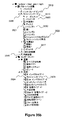
本開示のある局面において、複合物理モデルデータ(たとえばGUI330,439,549においてなされた選択)は、ユーザデータファイル(たとえば228)における格納のために、GUI(たとえば220)からデータストレージおよび抽出モジュール(たとえば224)へと通信され得るということが考えられる。たとえば、形状、材料、物理インターフェイス、メッシュ、検討および結果を含む、以前に図3−図5に記載されたモデルウィザードステップを介して生成されたもののような複合物理モデルは、GUIにおいてモデルツリーとして表わされ得る。モデルツリーにおけるノードを選択する(たとえば左クリックする)ことによって、当該ノードによって表わされる対応する動作のためのセッティングへのアクセスがユーザに与えられ得る。ノードのさらなる選択(たとえば右クリック)によって、ユーザが対応するノードに特性および動作を加え得るメニューへのアクセスがユーザに与えられ得る。これらの追加された特性および動作は、選択されたノードに対する子ノードとして表わされ得る。
In certain aspects of the present disclosure, compound physical model data (eg, selections made in
本開示のある局面において、上記の画面表示(たとえばGUI330)は、モデリングシステム(たとえば219)のGUIモジュール(たとえば220)のためのコンポーネントの部分によって表示され得、および/または、当該部分として含まれ得るということが考えられる。さらに、モデリングシステムが、予め規定され得るいくつかの物理インターフェイスおよび/またはユーザによって規定され得るいくつかの物理インターフェイスを含む異なるタイプの物理インターフェイスを含むように構成されるということが考えられる。予め規定された物理インターフェイスは、インターフェイス特性がライブラリ(たとえば226)に含まれ、かつ、たとえばベンダーから入手可能であり得る物理インターフェイスであり得る(たとえばベンダーは、伝熱のようなシステムの特定タイプについて、PDEの規定された系、解析タイプ、およびGUIなどを含むライブラリを供給し得る)。ユーザが規定した物理インターフェイスは、ユーザがPDEおよびモデリングされる量などを特定し得るユーザが規定したモデルまたは物理インターフェイスを可能にするように構成される。ユーザが規定したモデルは、ユーザデータファイル(たとえば228)に含まれるライブラリのようなユーザが規定したライブラリに保存され得る。ユーザが規定したモデルに関連付けられる定義および他のデータファイルは、たとえば、ライブラリ(たとえば226)のデータフォーマットと同様のさまざまなデータフォーマットのうちの任意の1つに格納され得る。フォーマットおよび動作は、格納されたモデルおよびモデルパラメータについて変動し得るということが考えられる。 In certain aspects of the present disclosure, the above screen display (eg, GUI 330) may be displayed by and / or included as part of a component for a GUI module (eg, 220) of a modeling system (eg, 219). It is possible to get. Further, it is contemplated that the modeling system is configured to include different types of physical interfaces including several physical interfaces that may be predefined and / or some physical interfaces that may be defined by a user. The pre-defined physical interface may be a physical interface whose interface characteristics are included in a library (eg, 226) and may be available from, for example, a vendor (eg, a vendor may have a specific type of system such as heat transfer). A library containing PDE defined systems, analysis types, GUIs, etc.). The user defined physical interface is configured to allow a user defined model or physical interface that allows the user to specify such things as the PDE and the amount to be modeled. The user defined model can be stored in a user defined library, such as a library included in a user data file (eg, 228). Definitions and other data files associated with a user-defined model may be stored in any one of a variety of data formats similar to, for example, a library (eg, 226) data format. It is contemplated that the format and behavior may vary for stored models and model parameters.
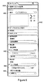
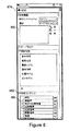
ここで図6を参照して、例示的な物理インターフェイスの物理的特性の特定(たとえば固体における伝熱)について、セッティングウィンドウ659の例示的な局面が示される。各物理インターフェイスは、その物理インターフェイスに関連付けられる物理的特性が特定され得る物理的現象またはプロセスにカスタマイズされた1つまたはいくつかのGUIセッティングウィンドウを有し得るということが考えられる。物理インターフェイスおよび物理インターフェイスのためのセッティングは、モデルツリーにおけるノードとして表わされ得る。たとえば、物理インターフェイスノードを選択する(たとえば右クリックする)ことにより、物理インターフェイスもしくはセッティングにドメイン特性を追加すること、ノードの名称を変更すること、または選択されたノードに関する特性を表示することといった1つ以上のタスクをユーザが行うことができるフォームが開かれ得る。
Referring now to FIG. 6, an exemplary aspect of the
セッティングウィンドウ659は、物理的特性が適用し得る1つ以上の形状ドメインを有し得るドメインリスト660を含む。このドメインは、サブドメインとも称され得る。ユーザが、グラフィックスウィンドウにおける形状ドメインのグラフィック表示から直接的に選択することによって、(たとえばマウス、キーボード、または他の選択機構を介して)1つまたはいくつかのサブドメインを選択し得るということが考えられる。さらに、ある局面において、ユーザは、複合物理モデルにおいてモデリングされるコンポーネントの具体的な部分を表わすドメインの予め規定された選択肢からドメインを選択し得るということが考えられる。
The
ドメイン(またはサブドメイン)の物理的特性はセッティングウィンドウにおいて特定される。前述のように、物理的特性は、数値662として特定されること、空間座標664での記号式として特定されること、物理量として特定されること、ならびにそれらの空間微分および/または時間として特定されることを含む異なる形態で表わされ得る。物理量はさらに、当該モデルの他のどこかで規定され得るとともに本願明細書において別記される材料セッティング666から得られ得るということが考えられる。さらに、特性の値を計算するプロシージャまたはルーチンを介して物理的特性が特定され得るということが考えられる。名称またはプロシージャもしくはルーチンが、含まれるべきパラメータがあれば当該パラメータと共に、セッティングウィンドウ659に入力され得る。1つの例示的な局面において、プロシージャまたはルーチンは、C、Visual Basic(登録商標)、Fortran、MATLAB(登録商標)またはMicrosoft Excel(登録商標)を使用して書かれ得る。ある実現例の場合の特定のプログラミング言語は、各特定の局面ならびに呼出規格およびそれに含まれる規則に従って変化し得る。
The physical characteristics of the domain (or subdomain) are specified in the settings window. As described above, physical properties are specified as
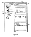
ここで図7を参照して、「方程式ビュー」ウィンドウを介してPDEを修正するために使用され得るGUI769の例示的な局面が示される。たとえば、例示的な方程式772のようなPDEは、物理インターフェイスによって規定され得、対応する特性についてのセッティングウィンドウにおいて規定され得ない記述を導入するためにユーザによって表示および修正され得る。1つの例示的な局面において、ユーザがメニューから「方程式ビューを表示」要素を選択することに応答して、PDEが表示され得る。ある局面において、モデルの各特性が、方程式に対する変更がユーザによってなされ得る対応するセッティングウィンドウ770とともに、対応する「方程式ビュー」を表示するということが考えられる。「方程式ビュー」は、物理インターフェイス特性ノード(たとえば要素776)に対する子ノード(たとえば要素774)として表わされ得る。ある局面において、「方程式ビュー」ノード(たとえば要素774)についてのセッティングウィンドウ770に対する変更の後、物理インターフェイス特性のための対応するセッティングがロックされ得るということが考えられる。1つの局面において、ロックの表示は、モデルツリーのそのインターフェイスについて1つ以上の特性がロックされることを示すように物理インターフェイスアイコン(たとえば要素776)上に配置され得る。また、当該特性は、対応する「方程式ビュー」ノード774についてのセッティングウィンドウにおいて、ユーザによってたとえば「すべてリセット」フィーチャ778または他のロック解除要素を選択することによりロック解除され得る。
Referring now to FIG. 7, an exemplary aspect of a
ここで図8を参照して、例示的な局面では、材料セッティングウィンドウ879がドメインの材料特性をセッティングするために示される。材料セッティングは、複合物理モデルに含まれる物理インターフェイスのうちのいくつかまたはすべてについての材料特性を含み得る。モデルは、ドメインリスト880において識別される異なるドメインについて選択される異なる材料を含み得るということが考えられる。材料特性はユーザによって規定され得るか、または、予め規定された材料ライブラリから得られ得る。材料セッティングウィンドウの1つの局面では、材料コンテンツ882のリストは、複合物理モデルにおける物理インターフェイスを考慮して、選択された材料について、選択されたドメインにおいて、材料特性のステータスを表示し得る。たとえば、例示的なジュール加熱プロセスの文脈において、材料コンテンツリストは、アイコンを使用して、ジュール加熱を伴う複合物理プロセスに関連付けられる特性と、複合物理インターフェイスにおいて記述された特性とをラベル付し得る。例示的な材料特性は、たとえば、熱容量、熱伝導率、電気伝導率、比誘電率および密度を含み得る。ジュール加熱を記述するための材料特性は、材料セッティングウィンドウ879を介して規定され得る。任意の必要な材料特性は、アイコン84または他の表示(たとえばチェックマーク)によりラベル付けまたは別の態様で識別され得る。必要な材料特性が規定されない場合、材料コンテンツ882のリストは、対応する材料特性の行を(たとえば赤い停止サインのアイコンを使用して)ハイライトすることによって、条件を識別し得る。
Referring now to FIG. 8, in an exemplary aspect, a
ユーザによって規定される材料および材料特性は、保存され得、その後、別個または異なるモデルにおける使用のために、ユーザが規定した材料ライブラリからアクセスされ得るということが考えられる。この局面は、ユーザが特定の用途のための材料ライブラリを作成することを可能にすることによって融通性を提供し、さらに、複合物理モデリングシステムとの使用のためにシステムディベロッパが材料ライブラリを作成することを可能にし得る。 It is contemplated that the user-defined materials and material properties can be stored and then accessed from a user-defined material library for use in separate or different models. This aspect provides flexibility by allowing users to create material libraries for specific applications, and system developers create material libraries for use with complex physical modeling systems. Can make it possible.
モデリングシステムにおける材料および材料特性は、ノードを介してモデルツリーにおいて表わされ得るということが考えられる。これにより、材料および材料特性が、表示、名称変更、および/または(たとえばモデルツリーにおける対応するノードを右クリックまたは別の態様で選択することにより)ユーザによってアクセス可能な形態でノードに追加されることが可能になり得る。 It is contemplated that materials and material properties in the modeling system can be represented in the model tree via nodes. This allows materials and material properties to be displayed, renamed, and / or added to the node in a form accessible by the user (eg, by right-clicking or otherwise selecting the corresponding node in the model tree). It may be possible.
ここで図9を参照して、物理インターフェイス(たとえば伝熱インターフェイス)についての物理的特性境界条件(たとえば温度)について、境界条件セッティングウィンドウ989の例示的な局面が示される。セッティングウィンドウ989は、物理的特性が適用され得る形状的境界を識別するよう境界リスト990を含み得る。ユーザは、1つ以上のグラフィックスウィンドウにおいて形状ドメインのグラフィック表示から境界を選択することによって、境界リストに1つ以上の境界を含み得るということが考えられる。境界の選択は、典型的に、コンピューティングシステムのために使用される選択タイプのデバイス(たとえばマウス、キーボード、他の選択デバイス)を介して行われ得る。さらに、ユーザはまた、複合物理モデルにおいてモデリングされるコンポーネントの境界の特定の部分を表わす境界の予め規定された選択肢から境界を選択し得るということが考えられる(たとえば境界選択)。当該特定の部分は、コンポーネントの境界全体またはコンポーネントの境界全体よりも小さいものを含み得る。
Referring now to FIG. 9, an exemplary aspect of a boundary
形状的境界の物理的特性は、対応する境界について境界条件セッティングウィンドウ989において特定され得る。上記特性は、空間座標での記号式としてまたは時間に基づいて、数値で特定された値992として表わされ得る。さらに、特性は、物理量、および、本願明細書において別記されたシステムを使用して加えられた物理インターフェイスからの対応する空間微分として、表わされ得るということが考えられる。さらに、特性の値を決定するプロシージャまたはルーチンは、本願明細書において別記されたものと同様の態様で特定および/または命名され得るということが考えられる。
The physical characteristics of the geometric boundary can be specified in the boundary
モデリングシステムにおける境界条件セッティングは、ノードを介してモデルツリーにおいて表わされ得るということが考えられる。これにより、ユーザが、物理インターフェイス境界条件に境界特性を加えること、ノードの名称を変更すること、または、(たとえばモデルツリーにおいて対応するノードを右クリックまたは別の態様で選択することによって)ノードに関する特性を表示することが可能になり得る。 It is possible that boundary condition settings in the modeling system can be represented in the model tree via nodes. This allows the user to add a boundary characteristic to the physical interface boundary condition, change the name of the node, or (for example, by right-clicking or otherwise selecting the corresponding node in the model tree) It may be possible to display the characteristics.
ここで図10を参照して、別の「方程式ビュー」フィーチャ1000を介してPDE境界条件を修正することについて、GUI1009の例示的な局面が示される。物理インターフェイスによって規定された境界条件は、対応する物理インターフェイスについてのセッティングウィンドウにおいて規定され得なかった記述を導入するために、ユーザによって1002にて表示および修正され得る。一実施形態において、境界方程式は、ユーザがプレファレンスメニュー(図示せず)からたとえば「方程式ビューを表示」するアイテムを選択することによって、表示され得る。「方程式ビュー」フィーチャ(たとえば方程式ビューノード1004)を使用するPDE境界方程式に対する変更の後、その境界条件についての対応するセッティングがロックされ得るということが考えられる。境界条件のロックされた性質を識別するために、モデルツリーにおける境界条件特性についての境界条件ノード1006は、ロックのように見える表示を含み得る。境界条件は、ユーザが、対応する特性について、1008にてセッティングウィンドウにおいて「すべてをリセット」または何らかの他のロック解除フィーチャを選択することによって、ロック解除され得る。
Referring now to FIG. 10, an exemplary aspect of the
モデリングシステムのある局面において、PDEの結合系に関連付けられるさまざまな選択された物理インターフェイスのためのPDEおよび境界条件が、図13−図15についての説明においてより詳細に記載されるモデルオブジェクト(たとえばモデルデータ構造)に格納されることが望ましくあり得るということが考えられる。モデルオブジェクトは、たとえば図7におけるGUI769を使用してPDEおよび境界条件が修正される場合、対応するモデルオブジェクトがこれにより更新され得るので、望ましくあり得る。たとえば、ドメインおよび境界についてそれぞれのセッティングウィンドウと、当該ドメインおよび境界についての物理的特性と、「方程式ビュー」において特定される可能な修正との使用を通じて、1つの例示的な局面におけるモデリングおよびシミュレーションモジュール222(たとえば図2参照)は、複合物理モデル(たとえば複合物理モデルデータ構造)に関連付けられるデータを含むモデルオブジェクトを作成、初期化、および修正し得る。さらに、PDEおよび関連付けられる境界条件のフィールドの結合系も同様に更新され得るということが考えられる。
In certain aspects of the modeling system, PDEs and boundary conditions for various selected physical interfaces associated with the coupled system of PDEs are described in more detail in the model object (eg, model It is conceivable that it may be desirable to be stored in a data structure. A model object may be desirable if the PDE and boundary conditions are modified using, for example,
ここで図11を参照して、別のタイプのセッティングウィンドウ1109の例示的な局面が、1つ以上の検討ステップを有する検討についての解答に関連して使用され得る検討ステップ(たとえば定常、時間依存、周波数)について示される。セッティングウィンドウ1109は、任意の1つ以上の物理インターフェイスまたは結合PDE系からの物理量のいずれかのサブセットについてPDEを解くことに関連付けられ得る。セッティングウィンドウ1109についてのGUIは、複合物理モデルについて選択される1つ以上の物理インターフェイスをリスティングする物理インターフェイス表示領域1110を含む。セッティングウィンドウ1109はさらに、異なるメッシュ1112と、異なる検討ステップについての異なる離散化1114および公差との選択を可能にするように構成され得る。対応する検討ステップセッティングと共に、モデルのための特定の物理インターフェイスが選択され得るということが考えられる。その後、対応するPDEが、異なる検討ステップにおいて一度に一つ解かれ得るか、または、対応するPDEが、各検討ステップにおいてPDEの結合系として、いくつかの物理インターフェイスについて解かれ得る。
Referring now to FIG. 11, an exemplary aspect of another type of
ここで図12を参照して、検討ノード(たとえば「検討1」1220)と、いくつかの子ノード(たとえば「ステップ1:定常」1222,「ソルバー構成」)とを含むモデルツリー1219の例示的な局面が示される。この例示的な局面における子ノードは、検討ステップ(たとえば「ステップ1:定常」1222,「ステップ2:時間依存」)と、ソルバーノード(たとえば「ソルバー1」1224)とを含む。親ノード(たとえば一次ノード)およびその子ノード(たとえば二次ノード,サブノード)は、モデルツリーにおけるブランチ(たとえば検討ブランチ1219)と称され得る。検討ブランチは、たとえば、PDE定式化(たとえば、「方程式をコンパイル:定常」1226a,「方程式をコンパイル:時間依存2」1226b)と、異なる検討(たとえば定常および時間依存の解析)についてのソルバーセッティング(たとえば「定常ソルバー1」1228a、「時間依存ソルバー1」1228b)とを含み得る。ユーザが、検討ステップの各々において解かれるモデル物理インターフェイスのサブセットを選択するか、または、すべての検討ステップにおいてすべての物理インターフェイスについて解くよう選択し得るということが考えられる。さらに、ユーザはまた、異なる空間次元に記述されるモデルを示す対応する物理インターフェイスを有するいくつかのモデルノード(たとえばモデルコンポーネントノード)を含み得、検討ステップの各々における物理インターフェイスのサブセットまたはすべての検討ステップにおけるすべての物理インターフェイスを解くということが考えられる。各検討ステップにおける物理インターフェイスおよび検討ステップについてのセッティングの選択も、モデルオブジェクトに含まれ得る。
Referring now to FIG. 12, an exemplary aspect of a
例示的なモデルツリー1219のソルバーブランチ(たとえばソルバー構成)は、検討ブランチ(たとえば検討1)に対する子ノードであり、さらにソルバー(たとえば「ソルバー1」)および/または従属変数ノード(たとえば「従属変数1」)のような自身の子ノードを含み得る。これらの子ノードはさらに、「mod1_V」1227aおよび「mod1_T」1227bといった付加的または自身の子ノードを有し得る。従属変数ノードはユーザがすべての検討ステップにおいてより精密な解の選択をすることが可能になるように構成され得るので、ソルバーは、物理インターフェイス内において個々の変数について解くまたは解かないようにセットされ得る。ソルバーステップおよびソルバーステップについてのセッティングにおける従属変数の選択もモデルオブジェクトに反映されるということが考えられる。
The solver branch (eg, solver configuration) of the
図3−図12において提示されるモデリングシステムの例示的な局面は、単に例であり、単に本願明細書において記載されたかまたは図において示されるプロセスまたは現象ではないより広い物理プロセスおよび物理的現象に適用されることが理解される。たとえば、多くの異なる物理インターフェイスが、図4に示される伝熱について選択された物理を越えて評価され得るということが理解されるであろう。また別の例として、複数の方程式ビューが図7に示され得るか、または、多くの異なる材料特性が図8において選択され得るということが理解されるであろう。示された局面は単に、複合物理モデリングシステムによって行なわれ得るより広い動作の例である。更に、示されたインターフェイスは、複合物理モデリングシステムにおいて使用され得る1つのタイプのインターフェイスを示す。他のタイプのグラフィカルインターフェイス、ユーザインターフェイス、または代替的な入力タイプインターフェイスが考えられる。 The exemplary aspects of the modeling system presented in FIGS. 3-12 are merely examples and broader physical processes and phenomena that are not simply the processes or phenomena described herein or shown in the figures. It is understood that it applies. For example, it will be appreciated that many different physical interfaces can be evaluated beyond the physics selected for the heat transfer shown in FIG. As yet another example, it will be appreciated that multiple equation views can be shown in FIG. 7, or that many different material properties can be selected in FIG. The aspect shown is merely an example of a wider operation that can be performed by a complex physical modeling system. Further, the interface shown illustrates one type of interface that can be used in a complex physical modeling system. Other types of graphical interfaces, user interfaces, or alternative input type interfaces are possible.
ここで図13−図15を参照して、単一結合形のPDEの系を表わすPDEの1つ以上の系を自動的に特定し、PDEの系について解くための動作を含む方法について、非限定的な例示的なフローチャート1329,1439,1549が示される。本開示について記載されるさまざまな局面は、オブジェクト指向プログラミング言語(たとえばJava(登録商標)、C++、C#)を使用して実現され得、オブジェクトは、インタラクションを伴う、データフィールドおよびメソッドを含むあるタイプのデータ構造である。たとえば、モデルにおけるオブジェクトは、モデルオブジェクトについてのメソッド呼出によって作成、修正、およびアクセスされ得る。モデルオブジェクトは、モデルについてのアルゴリズムおよびデータ構造を含み得、さらに当該モデルを表わすよう使用され得る。モデルオブジェクトはさらに、モデルについて形状、メッシュおよび解を作成するよう、動作のシーケンスをセットアップおよび実行するメソッドを含み得る。
Referring now to FIGS. 13-15, for a method that includes operations for automatically identifying and solving for one or more PDE systems representing a single coupled PDE system, A limited
さらに、モデルオブジェクトのメソッドは、メソッド呼出がモデルツリーにおいてノードによって表わされる動作に関連付けられ得るように、ツリーのような態様で構造化され得るということが考えられる。そのようなツリーのような構造またはモデルツリータイプの構造を用いて動作することによって、(たとえば親ノードとして表わされる)トップレベルのメソッドは、(たとえば子ノードによって表わされるか別の態様で表わされる)さらに別のメソッドをサポートする参照を返し得る。モデルオブジェクト内のあるレベルでは、メソッドは、モデルオブジェクトにデータを追加すること、計算を行なうこと、またはデータを返すことといったある動作を行なう。形状ノード(たとえば図29参照)の例示的な局面において、モデルオブジェクトは、形状ノードに対する二次ノード(たとえば子ノード)によって表わされるモデルの形状に関連付けられる異なる動作を有し得る。 Further, it is contemplated that model object methods can be structured in a tree-like manner so that method calls can be associated with actions represented by nodes in the model tree. By operating with such a tree-like structure or a model tree type structure, a top-level method (eg represented as a parent node) is represented (eg represented by a child node or otherwise) It may return a reference that supports yet another method. At some level within the model object, methods perform certain actions, such as adding data to the model object, performing calculations, or returning data. In the exemplary aspect of a shape node (eg, see FIG. 29), the model object may have different actions associated with the shape of the model represented by the secondary nodes (eg, child nodes) relative to the shape node.
ここで図13を参照して、ステップ1330では、モデリングシステムユーザによって、直接的(たとえば実際の選択)または間接的(たとえば予め規定されたフィーチャに関連付けられるステップを通じて)に、空間次元が選択される。空間次元の選択は、以前に図3に記載されたウィザードウィンドウを使用してまたは別のタイプのインターフェイスを通じて、行われることが望ましくあり得る。空間次元の選択は、メソッド呼出シンタックスであるmodel.modelNode().create()を有するモデルアイテム、および/または、メソッド呼出シンタックスであるmodel.geom().create().を使用して空間次元を特定する形状アイテムを用いるモデルオブジェクトの自動更新を含み得る。
Referring now to FIG. 13, in
次にステップ1331では、物理インターフェイスの選択が行なわれ得る。選択は、たとえば、図4について記載されたウィザードウィンドウを使用して行われ得る。物理インターフェイスの選択は、モデルオブジェクトを更新することと、model.physics().create()であるモデルオブジェクトに対応する物理アイテムを追加することとを含み得る。次に、ステップ1332では、検討のタイプが選択され得る。たとえば、以前に図5に記載されたウィザードウィンドウを使用して検討の選択が行われ得る。選択された検討は、方程式定式化およびソルバーセッティングを自動的に生成するよう後で使用され得るということが考えられる。さらに、モデルオブジェクトは、対応する検討アイテムであるmodel.study().create().で更新され得るということが考えられる。ある局面において、作成されたモデルオブジェクトアイテムのうちのいくつかまたはすべては、ノードによってモデルツリーにおいて表わされ得る子アイテムを備え得る。ノードは、モデルウィザードにおいておよび/または上に記載されたセッティングウィンドウにおいて特定された動作を記述し得る。
Next, in
ステップ1333aでは、物理インターフェイスについてのセッティングが選択されているかどうか決定がなされる。当該論理決定が真である場合、方法はステップ1333bに進み、ステップ1333bでは、モデルが加えられるべきかどうか別の決定がなされる。別のモデル(たとえばモデルコンポーネント)が、モデリングシステムによって既に受け取られているコンポーネントおよび/またはプロセスに加えられるべきである(すなわち真)場合、方法はステップ1330に戻り、当該付加的なモデルに関連付けられる入力を受け取る。次いで、既に利用可能なモデルとは異なるまたは同じ空間次元を有するモデルアイテムを含む新しいモデルアイテムであるmodel.modelNode().create()が加えられ得る。これは、複合物理モデルにおける複数のプロセスのシミュレーションを可能にする。付加的なモデルが加えるべきではない場合(すなわち偽)、方法はステップ1440に進み得る。ステップ1333aにおける論理決定が偽の場合、方法はステップ1334に進み、ステップ1334では、各物理インターフェイスについて、割り当てられた形状が点である0次元の物理インターフェイスを除いて、形状が特定される。形状表示は、作成されるか、またはそうでなければ形状ファイル(たとえばCADシステムを使用して作成されたファイル)からインポートされ得るということが考えられる。さらに、形状についてのモデルオブジェクトは、形状表示を含むよう更新され得るということが考えられる。
In
ステップ1335では、材料および対応する材料特性の特定がなされる。たとえば以前に図8に記載されるセッティングウィンドウを使用して材料および材料特性の選択が行なわれ得るということが考えられる。さらに、モデルオブジェクトは、対応する材料アイテムであるmodel.material().create()で更新され得るということが考えられる。次にステップ136では、異なるドメインにおける物理的特性であって、異なる物理インターフェイスについての物理的特性の特定が行われ得る。ドメインセッティングの特定は、たとえば以前に図6において記載されたセッティングウィンドウを使用して行なわれ得るということが考えられる。ステップ1337では、境界での物理的特性およびインタラクションは、異なる物理インターフェイスについて特定され得る。境界条件の特定は、たとえば以前に図9に記載されたセッティングウィンドウを使用して行なわれ得るということが考えられる。さらに、モデルオブジェクトは、model.physics().feature()というタイプのモデルオブジェクトアイテムを使用して、ドメインセッティングおよび境界条件の両方について更新され得るということが考えられる。
In
ステップ1338aでは、物理インターフェイスについてのPDEのうちのいずれかが修正されるべきであるかどうか決定がなされる。当該論理決定が真の場合、方法はステップ1338bに進み、ステップ1338bでは、ドメインの方程式および/または境界条件を含む、物理インターフェイスのうちのいくつかまたはすべてについての予め規定されたPDEが変更され得る。PDE修正ステップにおける予め規定された物理インターフェイス方程式の特定は、たとえば、以前に図7および/または図10に記載されたセッティングウィンドウを使用して行なわれ得るということが考えられる。ステップ1338bはさらに、モデルオブジェクトを更新することを含み得る。論理決定が偽の場合、または、PDE修正ステップが行なわれた後、当該方法はステップ1333aに戻り得る。
In
すべての物理インターフェイスの特定が完了し、かつ、モデリングされるコンポーネントおよび/またはプロセスについてさらにモデルが追加されない場合、当該方法は図14およびステップ1440に進み、メッシュが特定され得る(たとえば図11参照)。メッシュの特定は、メッシュアイテムであるmodel.mesh().create()でモデルオブジェクトを更新することを含み得るということが考えられる。次にステップ1441では、所望の検討パラメータがすべてモデルについて含まれているかどうか決定がなされる。論理決定が真の場合、方法はステップ1550に進む。論理決定が偽の場合、当該方法は、検討を追加、および/または、検討ステップを追加するためのステップに進む。たとえば、ステップ1442aでは、新しい検討が加えられるべきであるかどうか決定がなされる。論理決定が真の場合、当該方法はステップ1442bに進み、付加的な検討の選択が可能になる。付加的な検討は、検討アイテムであるmodel.study().create()に従って加えられ得るということが考えられる。付加的な検討の選択の後、または、ステップ1442aにおける論理決定が偽の場合、方法はステップ1443aに進み得、ステップ1443aでは、検討ステップが加えられるべきであるかどうか決定がなされる。論理決定が真の場合、当該方法は進み、ステップ1443bにて、検討ステップがモデルについて加えられることを可能にする。ひとたび検討ステップが選択されるか、または、ステップ1443aの論理決定が偽の場合、方法はステップ1444および1445に進み、検討ステップにおける物理インターフェイスが検討ステップセッティングと共に特定される。検討セッティングは、たとえば図11について記載されるセッティングウィンドウを使用して特定され得るということが考えられる。さらに、検討セッティングは、model.study().feature().set().のタイプの1つまたはいくつかのアイテムに従ってモデルオブジェクトを更新し得るということが考えられる。検討セッティングの完了の後、当該方法はステップ1550に進む。
If all physical interfaces have been identified and no further models are added for the component and / or process being modeled, the method can proceed to FIG. 14 and
ここで図15を参照して、ステップ1550ではソルバーシーケンスが生成され、ソルバーが完了していると決定されるかどうかに依存してステップ1551での決定に基づいて、ステップ1552ではソルバーシーケンスが編集され得る。ソルバーシーケンスは、モデルオブジェクトに関連付けられる検討に基づいて、アイテムであるmodel.sol().create()を作成することによりモデルオブジェクトを更新し得るということが考えられる。さらに、アイテムがmodel.sol().feature().create()というモデルオブジェクトアイテムに従って加えられた状態で、ソルバーシーケンスが編集され得るということが考えられる。その後、ステップ153では、上記方法はPDEを解き、モデルについての解を生成し得る。解答ステップは、model.sol().runAll()というモデルアイテムによって更新され得るということが考えられる。
Referring now to FIG. 15, a solver sequence is generated at
図13−図15において記載されたものは単に、異なる空間次元において1つ以上の物理インターフェイスおよび1つ以上の形状表示(たとえばコンポーネントまたはプロセスを表わすモデル)に関連付けられる1つ以上セットのPDEを自動的に形成する方法の非限定的な例示的な局面である。当該方法のある局面において、PDEは、PDEの単一の結合系へと組み合わせられ得るということが考えられる。有限要素ソルバーのような数値ソルバーが、たとえばモデリングおよびシミュレーションモジュール(たとえば222)に含まれ得、PDEの系を解くよう使用され得る。たとえば有限要素ソルバーは、単一の物理インターフェイスに対応するPDEの単一系を解き得、または、いくつかの物理インターフェイスおよびいくつかの形状表示(たとえばモデルノードによって表わされる)に対応するPDEの結合系について解き得る。 What is described in FIGS. 13-15 simply automates one or more sets of PDEs associated with one or more physical interfaces and one or more shape representations (eg, models representing components or processes) in different spatial dimensions. FIG. 3 is a non-limiting exemplary aspect of a method of forming automatically. It is contemplated that in certain aspects of the method, PDEs can be combined into a single coupled system of PDEs. A numerical solver, such as a finite element solver, can be included in a modeling and simulation module (eg, 222), for example, and can be used to solve a system of PDEs. For example, a finite element solver can solve a single system of PDEs corresponding to a single physical interface or a combination of PDEs corresponding to several physical interfaces and several shape representations (eg represented by model nodes) It can be solved for the system.
ここで図16を参照して、アプリケーションデータ構造(たとえばアプリケーションオブジェクト)を作成または形成するための方法のいくつかの局面についての方法ステップを含むフローチャートが示される。当該方法は、本願明細書において別記されるシステムおよび装置の任意の1つ上で実現され得る。示される方法ステップは、アプリケーションビルダーモジュールにおけるユーザインターフェイスによってユーザに利用可能であり得る。本開示のいくつかの局面において、記載された方法によって作り出されるまたは作成されるアプリケーションデータ構造は、本願明細書において別記されるシステムのような複合物理モデリングシステムにロードされて(複合物理モデリングシステムにおいて実行されて)、複合物理モデルにおいて選択されたセッティングを制御するための対応するアプリケーションモデルツリーを有するカスタマイズされたアプリケーションモデルを生成し得る。ある局面において、結果得られるアプリケーションデータ構造は、複合物理モデリングシステムにロードされる(または実行される)と複合物理モデリングシステムデスクトップをカスタマイズするそれ自身のアプリケーション固有デスクトップ設計への参照を含み得る。その後、アプリケーション自身のユーザインターフェイスにおいてユーザによってアプリケーションモデルがアクセスされ得る。 Referring now to FIG. 16, a flowchart is shown that includes method steps for some aspects of a method for creating or forming an application data structure (eg, an application object). The method can be implemented on any one of the systems and devices described elsewhere herein. The method steps shown may be available to the user through a user interface in the application builder module. In some aspects of the present disclosure, application data structures created or created by the described methods are loaded into a complex physical modeling system, such as the system described elsewhere herein (in a complex physical modeling system). Once executed, a customized application model may be generated having a corresponding application model tree for controlling selected settings in the composite physical model. In certain aspects, the resulting application data structure may include a reference to its own application-specific desktop design that customizes the composite physical modeling system desktop when loaded (or executed) into the composite physical modeling system. The application model can then be accessed by the user in the application's own user interface.
アプリケーションデータ構造を作成または形成するための方法ステップは、複合物理モデル1600aを作成または選択し、対応する複合物理モデルデータ構造(たとえばモデルオブジェクト)1600bを当該方法に関連付けられるシステム上に抽出またはロードすることにより開始され得る。いくつかの局面において、複合物理モデルデータ構造は、初期のアプリケーションデータ構造1600dにおいて、埋込モデルとして1600cにて埋め込まれ得るということが考えられる。さらに、いくつかの局面において、アプリケーションファイルとしての複合物理モデルのメモリデバイスへの保存または格納により、対応する埋込モデルを有する初期のアプリケーションデータ構造が作成され得るということが考えられる。いくつかの局面において、アプリケーションデータ構造の作成または形成はさらに、埋込モデル1600e(および埋込モデルデータ構造)に形状サブルーチンを追加する動作を含み得る。その後、追加された形状サブルーチンも、アプリケーションデータ構造1600dに埋め込まれる。
A method step for creating or forming an application data structure creates or selects a compound
ある局面において、カスタマイズされた(たとえば、アプリケーション固有の)デスクトップフィーチャは、アプリケーションデータ構造に追加または埋め込まれ得る。デスクトップフィーチャはアプリケーションツリーにノードとして表わされ得る。デスクトップフィーチャは、アプリケーションの実行の際、ウィンドウ、ウィジェットおよびフォームを含むデスクトップウィンドウを表示し得る。複合物理モデリングシステムのデスクトップにおいてアプリケーションが実行されるある局面において、デスクトップフィーチャは必要とされ得るか、または、必要とされ得ない。 In certain aspects, customized (eg, application specific) desktop features may be added or embedded in the application data structure. Desktop features can be represented as nodes in the application tree. The desktop feature may display a desktop window that includes windows, widgets, and forms during execution of the application. In certain aspects where an application is run on the desktop of a complex physical modeling system, desktop features may or may not be required.
次に、ステップ1620では、アプリケーションデータ構造を作成および形成するためのステップの別の局面が記載され、当該別の局面では、アプリケーションフィーチャはアプリケーションデータ構造に追加され得る。アプリケーションフィーチャは、アプリケーションツリーおいてアプリケーションノードによって表わされ得る。アプリケーションフィーチャは、結果得られるアプリケーションデータ構造から作成されるアプリケーションモデルツリーにアプリケーションモデルノードを加えるよう使用され得る。アプリケーションモデルツリーにおけるアプリケーションモデルノードは、複合物理モデルのようなモデルにおけるセッティングを参照するよう特定され得る。アプリケーションフィーチャはさらに、アプリケーションデータ構造が実行されると、アプリケーションのデスクトップまたはウィンドウにおける(ボタン、コンボボックスまたはチェックボックスのような)ウィジェットまたはフォームからアプリケーションモデルに追加され得る。
Next,
アプリケーションフィーチャは初期のアプリケーションデータ構造に適用され、カスタマイズされたアプリケーションモデルデータ構造を作成するために使用される。アプリケーションフィーチャは、タイプ、記述およびアイコンによって識別され得る。タイプ識別子は、アプリケーションデータ構造におけるアプリケーションフィーチャを参照するよう使用され得る一意の識別子であり、アプリケーションビルダーモジュールが動作しているシステムに関連付けられるGUIに表示され得るように、アプリケーションビルダーモジュールにおけるアプリケーションツリーにおけるフィーチャの隣にさらに表示され得る。記述識別子は、結果得られるアプリケーションモデルツリーにおいてグラフィカルユーザインターフェイスに表示され得、アプリケーションモデルツリーにおけるノードが表わす動作をさらに示し得る。記述または識別子も、アプリケーションモデルツリーにおけるノードに対する代替例として、デスクトップまたはウィンドウにおけるウィジェットまたはフォームに表示され得る。アイコンのグラフィックスを含む画像ファイルを指し得るアイコン識別子はさらに、アプリケーションデータ構造に関連付けられるアプリケーションがコンピュータシステム上で実行される際に示されるアプリケーションモデルツリーまたはウィジェットもしくはフォームにおいてアイコングラフィックスを表示し得る。 Application features are applied to the initial application data structure and used to create a customized application model data structure. Application features can be identified by type, description and icon. The type identifier is a unique identifier that can be used to refer to application features in the application data structure and in the application tree in the application builder module so that it can be displayed in the GUI associated with the system on which the application builder module is running. It can be further displayed next to the feature. The descriptive identifier may be displayed on the graphical user interface in the resulting application model tree and may further indicate the behavior represented by the node in the application model tree. A description or identifier may also be displayed on a widget or form in the desktop or window as an alternative to a node in the application model tree. An icon identifier that may point to an image file that contains icon graphics may further display icon graphics in an application model tree or widget or form that is shown when an application associated with the application data structure is executed on the computer system. .
いくつかの局面において、アプリケーションフィーチャは、制限およびプレファレンスにより規定され得、その後、アプリケーションモデルツリーにおける対応するアプリケーションモデルノードに適用され得るか、または代替例として、デスクトップまたはウィンドウにおける対応するウィジェットまたはフォームに適用され得る。上記制限は、アプリケーションモデルノードが単に別のノードの後に提示され得るように、たとえばこのようなノードが前のノードによって表わされる動作に依存する際に提示され得るように、規定され得る。いくつかの局面において、プレファレンスは、アプリケーションモデルノードまたはウィジェットもしくはフォームがアプリケーションモデルツリーまたはデスクトップもしくはウィンドウにおいてデフォルトで示されるように、または、アプリケーションモデルノードがアプリケーションモデルツリーにおいてシングルトンノードとして存在し得るように、規定され得る。局面において、このようなシングルトンノードは、たとえば初期値または条件のようなセッティングを規定するよう、アプリケーションモデルツリーに一回のみ加えられ得る。 In some aspects, application features can be defined by restrictions and preferences and then applied to the corresponding application model node in the application model tree, or alternatively, the corresponding widget or form in the desktop or window Can be applied to. The above restrictions can be defined so that an application model node can be presented simply after another node, for example when such a node can be presented depending on the behavior represented by the previous node. In some aspects, the preference is such that the application model node or widget or form is shown by default in the application model tree or desktop or window, or the application model node may exist as a singleton node in the application model tree. Can be defined. In an aspect, such a singleton node can be added only once to the application model tree to define settings such as initial values or conditions.
次にステップ1630では、入力宣言がアプリケーションデータ構造に加えられ得る。入力宣言は、新しいデータフィールドを宣言するために使用され、各データフィールドは一意の識別子、名称、随意の記述またはその組合せを有し得る。いくつかのタイプの入力宣言が考えられる。たとえば、ストリングデータフィールドがストリング値を宣言するよう適用され得、ストリングアレイデータフィールドが任意長のストリングのアレイを宣言するよう適用され得、または、ダブルストリングアレイデータフィールドが外部および内部レベルについて任意長を有するストリングのダブルアレイ(たとえばアレイ要素もアレイであるアレイ)を宣言するよう適用され得る。別の例として、バイナリデータフィールドが、バイナリ形式(たとえばシリアライゼーション)を使用してより効率的に任意のタイプのデータを格納し得るフィールドを宣言するよう適用され得る。多くの浮動小数点の数を格納するデータフィールドは、バイナリフィールドとして格納することが望ましくあり得るフィールドの例であるが、たとえばストリングのアレイを用いて別の態様でそのようなフィールドを表わすことは可能である。さらに、埋込モデル(たとえばアプリケーションデータ構造に埋め込まれたモデル)におけるデータフィールドのいずれも入力宣言として使用され得ることが考えられる。このようなデータフィールドは、ひとたび宣言されると、作成または形成されたアプリケーションデータ構造に基づいてアプリケーションのユーザによってアクセスされ得る埋込モデルにおけるパラメータであり得る。
Next, in
次にステップ1640において、ウィンドウ、入力フォームおよびフォームの集合がアプリケーションデータ構造に加えられ得る。いくつかの局面において、入力フォームは、アプリケーションが実行される際に、異なるユーザ動作を監視またはモニターするウィジェットまたはウィジェットの集合を表わすということが考えられる。ウィジェットは、アプリケーションと相互に作用するよう情報を表示するかもしくはユーザについての特定の態様を提供するグラフィカルユーザインターフェイスの要素を含み得るか、または、ウィジェットはまた、GUIの特定の要素がどのように見えるか、当該要素がどのように振る舞うか、および、当該要素がどのようにユーザのアクションに応答して相互作用するかを記述する短いプロセスであり得る。入力フォームは、アプリケーションフィーチャに関連付けられるウィンドウまたはメニューに加えられ得る。アプリケーションビルダーモジュールは、たとえばセッティングウィンドウを作成するために適用され得る予め規定されたテンプレートフォーム、フォームの集合およびウィジェットの集合を含み得るということが考えられる。
Next, at
ここで、入力フォームのいくつかの例示的な局面が記載される。
テキスト入力フォームは、典型的にはテキストボックスに存在するが常にテキストボックスに存在するわけではない、何らかのストリングデータの値にリンクするテキストフィールドを含み得る。いくつかの局面において、リンクは、受け取られたテキスト入力またはコンボボックスから受け取られた入力といった何らかの受け取られた入力に基づき得るストリングデータの値をテキストフィールドに割り当てることを含み得る。図25はさらに、テキスト入力フォームにおいて受け取られた入力が埋込モデルにおいて内部データフィールドに関連付けられ得る(たとえばアクチュエータ長さについての例示的なパラメータL)リンクの局面を例示する。図34は、コンボボックス(たとえば例示的なインペラタイプ3426)がデータフィールド(たとえば例示的なインペラタイプフィールド3405)の値をセットするリンクの別の局面を例示する。コンボボックス入力フォームのためのセッティングは、いくつかの局面において、テキスト入力フォーム(たとえば図25)についてのセッティングと同様であると考えられる。
Several exemplary aspects of the input form will now be described.
A text entry form may include a text field that links to the value of some string data that is typically present in the text box but not always present in the text box. In some aspects, the link may include assigning a string field a value of string data that may be based on some received input, such as a received text input or an input received from a combo box. FIG. 25 further illustrates aspects of a link where an input received in a text input form can be associated with an internal data field in an embedded model (eg, exemplary parameter L for actuator length). FIG. 34 illustrates another aspect of a link where a combo box (eg, exemplary impeller type 3426) sets the value of a data field (eg, exemplary impeller type field 3405). The settings for the combo box input form may be similar in some aspects to the settings for the text input form (eg, FIG. 25).
アプリケーションフィーチャにおけるストリングデータフィールドオブジェクトのうちのいずれかを選択することを除いて、埋込モデルにおけるストリングデータ値も選択され得る。このようなストリングデータ値の例がモデルパラメータを含む。コンボボックスフォームは、たとえばストリングデータフィールドといった何らかのストリングデータの値を含み得る選択肢のリストを表示するために使用され得る。当該セッティングは、テキスト入力のセッティングと同様であり得る。チェックボックスフォームは、アプリケーションが実行される際に、ユーザがたとえばオンまたはオフといった2つの選択肢同士の間で選択することを可能にするために適用され得る。ボタンフォームは、アプリケーションにおいてクリックまたは別の態様で選択されると、アクションを行なうようウィジェットの集合において使用され得る。メニューアイテムフォームは、子であるメニューについてのメニューアイテムを規定し得る。親は、メニューまたはアプリケーションフィーチャであり得る。親としてアプリケーションフィーチャを有するメニューアイテムフォームは、アプリケーションが実行される際に、アプリケーションフィーチャについてコンテキストメニューに含まれ得る。テーブル入力フォームは、ストリングアレイデータフィールド宣言の値に対する編集を提供し得、通常、テーブルの1列につき1フィールド参照である。 Except for selecting any of the string data field objects in the application features, string data values in the embedded model can also be selected. Examples of such string data values include model parameters. The combo box form can be used to display a list of choices that can include the value of some string data, for example a string data field. The setting may be similar to the text input setting. A check box form may be applied to allow the user to select between two options, for example on or off, when the application is run. A button form can be used in a collection of widgets to perform an action when clicked or otherwise selected in an application. A menu item form may define menu items for child menus. The parent can be a menu or application feature. A menu item form with an application feature as a parent can be included in the context menu for the application feature when the application is run. The table entry form may provide editing for the value of the string array data field declaration, typically one field reference per column of the table.
フォームの集合は、アプリケーションのユーザインターフェイスのための所望のレイアウトを達成するために、メンバーフォームの集合をグループ化するよう適用され得る。メンバーフォームは、入力フォームまたは出力フォームであり得(以下参照)、さらにメンバーとしてウィジェットを含み得る。フォームの集合におけるメンバーは、入力フォームおよび出力フォームへの参照によって、または、子(たとえばモデルツリーの局面における子ノード)としてフォームの集合に直接的に入力フォームおよび出力フォームを加えることによって、加えられ得る。 The collection of forms can be applied to group the collection of member forms to achieve the desired layout for the user interface of the application. The member form can be an input form or an output form (see below) and can further include a widget as a member. Members in a set of forms are added by reference to the input and output forms, or by adding the input and output forms directly to the set of forms as children (eg, child nodes in a model tree aspect) obtain.
いくつかのタイプのフォームの集合は、アプリケーションビルダーモジュールのいくつかの局面において利用可能であり得るということが考えられる。デスクトップウィンドウは、あるタイプのフォームの集合であり得、いくつかの局面では、デスクトップウィンドウフォームの集合は、他のフォームがアプリケーションの実行の際に表示され得るコンピュータデスクトップにおけるフレームを規定し得る。 It is contemplated that a collection of several types of forms may be available in some aspects of the application builder module. A desktop window may be a collection of certain types of forms, and in some aspects, a collection of desktop window forms may define a frame in the computer desktop where other forms may be displayed during execution of the application.
セクションパネルは、デスクトップウィンドウまたはフォームウィンドウの内部に示され得、さらに、作成されたアプリケーションデータ構造に基づいたアプリケーションが実行される場合、アプリケーションフィーチャに関連付けられ得る。このようなセクションパネルは、たとえばバーの下に配置される記述およびメンバーフォームを示す見出しバーを含み得る。フォームウィンドウは、少なくとも1つのセクションパネルを含み得、アプリケーションフィーチャは自動的に1つのセクションパネルの子を取得し得るということがさらに考えられる。 The section panel can be shown inside a desktop window or form window and can be associated with an application feature when an application based on the created application data structure is executed. Such a section panel may include, for example, a description bar located below the bar and a heading bar showing the member form. It is further envisaged that the form window may include at least one section panel and the application feature may automatically obtain a child of one section panel.
アプリケーションビルダーモジュールにおいて利用可能な別のタイプのフォーム集合はメニューを含み得る。メニューはたとえば、作成されたアプリケーションデータ構造に基づいたアプリケーションが実行されると、デスクトップウィンドウにおけるツールバーにおいてアクセスされ得るか、または、アプリケーションノードについてのコンテキストメニューとしてアクセスされ得る。メニューは、子フィーチャとしての少なくとも1つのメニューアイテムまたは子フィーチャとしての少なくとも別のメニューを含み得る。メニューは、アプリケーションビルダーモジュールにおいてその記述について1つ以上のセッティングを含み得る。 Another type of form collection available in the application builder module may include menus. The menu can be accessed, for example, in a toolbar in the desktop window or as a context menu for the application node when an application based on the created application data structure is executed. The menu may include at least one menu item as a child feature or at least another menu as a child feature. A menu may contain one or more settings for its description in the Application Builder module.
フォームのグループは、アプリケーションビルダーモジュールにおいて利用可能なさらに別のタイプのフォームの集合であり得る。フォームのグループは、1つの新しいフォームへと他のいくつかのフォームを構成するよう適用され得る。1つのこのような例は、作成されたアプリケーションデータ構造に基づいたアプリケーションが実行される場合にいくつかのフォームがデスクトップウィンドウまたはセッティングウィンドウにおいて互いの上に示される場合を含む。 A group of forms may be a collection of yet another type of form available in the application builder module. A group of forms can be applied to compose several other forms into one new form. One such example includes the case where several forms are shown on top of each other in a desktop window or settings window when an application based on the created application data structure is executed.
カードスタックは、さらに別のタイプのフォームの集合であり得る。このようなフォームの集合は、作成されたアプリケーションデータ構造に基づいたアプリケーションの実行中にシステムユーザによってなされた選択に依存して示される多くの予め規定されたフォームを含み得る。いくつかの局面において、カードスタックにおけるメンバーでもあるフォームの単一のメンバーのみが、このようなフォームの集合を含むアプリケーションが実行される場合に、所定の時間でアクティブになることが可能になるということが考えられる。示されるカードスタックにおけるフォームのうちのどれかを制御することは、以下により詳細に記載されるアクティベーション条件を適用することにより実現され得る。 A card stack can be a collection of yet another type of form. Such a collection of forms may include a number of predefined forms that are presented depending on selections made by the system user during execution of the application based on the created application data structure. In some aspects, only a single member of a form that is also a member in the card stack will be able to be active at a given time when an application that includes such a collection of forms is executed. It is possible. Controlling any of the forms in the card stack shown can be achieved by applying activation conditions described in more detail below.
フォームの集合の他の局面は、デスクトップウィンドウを含み得る。デスクトップウィンドウのフォームの集合は、作成されたアプリケーションデータ構造に基づいたアプリケーションが実行される場合に他のフォームが表示され得るコンピュータデスクトップにおけるフレームを規定し得る。フォームウィンドウは、特定および予め規定されたタイプのデスクトップウィンドウであり得る。フォームウィンドウは、他のフォームが行および列で示されるとともに位置決めされ得るフレームを規定し得る。フォームウィンドウはさらに、作成されたアプリケーションデータ構造に基づいたアプリケーションの実行中に、すべてのアプリケーションフィーチャに関連付けられるアプリケーションセッティングウィンドウについてのデフォルトウィンドウであり得る。キャンバスウィンドウは、さらに別のタイプの特定および予め規定されたデスクトップウィンドウであり、したがって、フォームの集合でもある。キャンバスウィンドウは、アプリケーションが実行されると、形状、メッシュおよびプロットのようなグラフィックスを表示するよう使用され得る。 Other aspects of the form collection may include a desktop window. A collection of forms in the desktop window may define a frame in the computer desktop where other forms can be displayed when an application based on the created application data structure is executed. A form window may be a specific and predefined type of desktop window. A form window may define a frame in which other forms are shown and positioned in rows and columns. The form window may further be the default window for the application settings window associated with all application features during execution of the application based on the created application data structure. A canvas window is yet another type of specific and predefined desktop window, and thus also a collection of forms. The canvas window can be used to display graphics such as shapes, meshes and plots when the application is run.
次にステップ1650において、アクティベーション条件が、ステップ1640において加えられた入力フォームまたはフォームの集合に加えられ得る。アクティベーション条件は、入力宣言の値をチェックする論理条件を特定するよう適用され得る。たとえば、入力フォームについて、アプリケーションの実行の間にフォームウィンドウにおいてフォームが有効または無効にされるかどうかを決定するよう、アクティベーション条件が適用され得る。無効にされたフォームは、ウィンドウから隠されるかまたは非アクティブ状態へとグレイアウトされ得る。
Next, in
次に、ステップ1660において、出力宣言はアプリケーションデータ構造に加えられ得る。出力宣言は、アプリケーションが実行される際にユーザによって変更され得ないデータフィールドを宣言するよう適用され得る。その代わりに、宣言されたデータフィールドは、アプリケーションデータ構造におけるアプリケーションまたは埋込モデルから値を読み出すために使用され得る。たとえば出力宣言は、アプリケーションデータ構造に基づいたアプリケーションが実行される際に、埋込モデルにおける評価からの結果を宣言するために使用され得る。
Next, in
次にステップ1670において、出力フォームまたはフォームの集合は、アプリケーションデータ構造に加えられ得る。出力フォームは、データを提示する埋込モデルにおいて出力宣言またはオブジェクトからのデータを表示する任意のウィジェットを表わし得る。埋込モデルにおけるプロットグループは、キャンバスウィンドウにおいて直接的に使用され得る出力フォームの例である。いくつかの局面において、出力フォームは、アプリケーションデータ構造に基づいたアプリケーションの実行中にアクションの結果を更新および表示するために、アクションステップ(以下参照)によって更新されるということが考えられる。
Next, at
複数の出力フォームが、アプリケーションデータ構造を生成するよう使用されるアプリケーションビルダーモジュールにおいて、規定することが望ましくあり得るということが考えられる。データ表示出力フォームは、出力宣言のために表示を特定するよう適用され得る。データ表示出力フォームはさらに、アプリケーションデータ構造に加えられる埋込モデルにおいて、全体評価への参照を含み得る。このような全体評価の値は、アプリケーションの実行の間にフォームがアクションによって実行される際に更新され得る。テーブルデータ表示出力フォームは、出力宣言からの多くの出力データを提示する望ましい態様であり得る。たとえば、テーブルの1列につき1つの出力参照を使用することが可能であり得る。さらにエクスポート出力フォームが、アプリケーションの実行の間にファイルに結果を保存するために、エクスポートダイアログを開くよう使用され得る。エクスポート出力フォームは、アプリケーションデータ構造に加えられる埋込モデルにおけるエクスポートオブジェクトを指し得、たとえばアニメーション、イメージおよびデータを含み得る。 It is contemplated that multiple output forms may be desirable to define in an application builder module that is used to generate an application data structure. The data display output form can be applied to specify a display for output declaration. The data display output form may further include a reference to the overall evaluation in an embedded model that is added to the application data structure. Such global rating values may be updated as the form is executed by the action during application execution. A table data display output form may be a desirable way to present a lot of output data from an output declaration. For example, it may be possible to use one output reference per column of the table. In addition, an export output form can be used to open an export dialog to save the results to a file during application execution. An export output form may refer to an export object in an embedded model that is added to the application data structure, and may include, for example, animation, images and data.
次に、ステップ1680において、アクティベーション条件は、出力フォームに加えられ得る。このようなアクティベーション条件は、出力フォームが表示されるべきかまたは表示されるべきでないかを決定するよう適用され得る。たとえば、アクティベーション条件は、アプリケーションの実行中に出力フォームがフォームウィンドウにおいて有効化または無効化されるかどうかを決定し得る。無効なフォームは、アプリケーションの実行の間に、ウィンドウから隠され得るか、または、ただグレイアウトされ得る。
Next, in
次に、ステップ1690において、アクションがアプリケーションデータ構造に加えられ得る。アクションは、動作のシーケンスについての定義を含み得、作成されたアプリケーションデータ構造に基づいたアプリケーションの実行中に入力フォームから実行され得る。たとえば、アクションまたはシーケンスの定義は、ボタンまたはアイコンの選択の受け取りに応答してまたは当該受け取りの後に、入力フォームから実行され得る。アクションはさらに、出力フォームの更新を含み得る。たとえばアクションは、埋込モデルにおいてプロットの更新を含み得、これにより次いで、たとえばキャンバスウィンドウを使用してアプリケーションにおけるグラフィックスウィンドウにおいて新しいプロットを生成する。
Next, at
次に、いくつかの局面において、ステップ1695が考えられる。ステップ1695において、ウィザードがアプリケーションデータ構造に加えられ得る。ウィザードは、一度に1つまたはさまざまな組合せでGUI上に表示され得るウィンドウのシーケンスを特定するよう適用され得る。ウィザードは、アプリケーションルートノードの直下に配置され得、作成されたアプリケーションデータ構造に基づいたアプリケーションの実行または実現中に新しいアプリケーションモデルが作成されるとスタートされ得る。いくつかの局面において、ウィザードは、アプリケーションフィーチャに対する子としてセットアップされ得、アプリケーションフィーチャの新しいインスタンスがアプリケーションの実行の間に作成されるとスタートされ得る。いくつかの局面において、ウィザードは、子ノードである少なくとも1つのウィザードステップを含むということが考えられる。そのような子ノードのウィザードステップは、ウィザードにおける各ステップについてウィンドウの特定を含み得る。たとえば、いくつかの局面において、各ウィザードステップは、セッティングウィンドウフォームにおいて規定され得る異なるウィンドウを含み得る。
Next, in some aspects,
次に、当該方法は、付加的なアプリケーションフィーチャが決定または追加されるべきかどうかを決定するよう進む。そうでなければ、当該方法はステップ16100に進み、アプリケーションデータ構造が上記の方法ステップからの出力として生成される。 The method then proceeds to determine whether additional application features are to be determined or added. Otherwise, the method proceeds to step 16100, where an application data structure is generated as output from the above method step.
いくつかの局面において、アプリケーションデータ構造は、アプリケーションが基づくモデルからの、埋込モデルとして複合物理モデルデータ構造と、上記の方法ステップによって生成されるノードを表わす階層とを含むということが考えられる。 In some aspects, it is contemplated that the application data structure includes a composite physical model data structure as an embedded model from the model on which the application is based and a hierarchy representing the nodes generated by the above method steps.
さらに、更新または修正されるアプリケーションデータ構造の展開ステップは、新しいまたは既存のライブラリにアプリケーションデータ構造を配置することを含み得るということが考えられる。ライブラリは、ファイルシステム上またはネットワークにおける実際のフォルダ構造を表わし得る。既存のライブラリのうちのいずれかは、アプリケーションデータ構造に基づいて複合物理モデルデータ構造を作成するよう構成または適合されるシステムによってアクセスされ得る。 Further, it is contemplated that the step of deploying an application data structure that is updated or modified may include placing the application data structure in a new or existing library. The library may represent the actual folder structure on the file system or in the network. Any of the existing libraries may be accessed by a system that is configured or adapted to create a composite physical model data structure based on the application data structure.
アプリケーションフィーチャを追加しアプリケーションデータ構造を生成するための上記の方法が物理システムのモデルに関連付けられるということが考えられる。入力宣言、フォームフィーチャ、アクティベーション条件およびアクションフィーチャを含むアプリケーションフィーチャは、アプリケーションフィーチャを含む修正または更新されたアプリケーションデータ構造を形成または生成する部分として追加、取得、受信、または送信されるデータとして表わされると考えられる。 It is possible that the above method for adding application features and generating application data structures is associated with a model of a physical system. Application features, including input declarations, form features, activation conditions, and action features are represented as data that is added, retrieved, received, or transmitted as part of forming or generating a modified or updated application data structure that includes application features. It is thought that.
図17を参照して、図16に記載されるプロセスについてのアクションによって作成されるアプリケーションデータ構造のいくつかの局面におけるフィーチャ同士の間のインスタンスレベルの関係の統一モデリング言語(unified modeling language(UML))オブジェクトの図の例が示される。 Referring to FIG. 17, a unified modeling language (UML) of instance level relationships between features in some aspects of the application data structure created by actions on the process described in FIG. ) An example diagram of an object is shown.
アプリケーションデータ構造は、少なくとも1つの埋込モデル1701および少なくとも1つのアプリケーションフィーチャ1702を含み得る。代替例として、アプリケーションデータ構造は、デスクトップウィンドウ、フォームおよびウィジェットを有するデスクトップを含み得る。複数または1つ以上の埋込モデルおよびアプリケーションフィーチャも考えられる。アプリケーションデータ構造は、入力宣言1703の1つ以上(たとえば1...*)と、対応するアクティベーション条件1714によりさらに規定され得る1つ以上の入力フォーム1704とを含み得る。アプリケーションデータ構造はさらに、0から1〜複数(たとえば0...*)までのいずれかの出力宣言1705と、さらに対応するアクティベーション条件1715を含み得る出力フォーム1706とを含み得る。1つ以上(たとえば0...*)のフォームの集合はさらにアプリケーションフィーチャ1702に含まれ得る。そのような集合は、入力フォームおよび/または出力フォームを含み得る。0から1つ以上(たとえば0...*)のアクション1708は、0から1つ以上(たとえば0...*)の対応するアクティベーション条件1716で規定され得るアプリケーションデータ構造に含まれ得る。いくつかの局面において、アプリケーションフィーチャのセッティングはさらに、ウィザードフィーチャ1712に含まれるウィザードステップ1713にリンクされ得る。さらに、アプリケーションフィーチャはまた、自身の対応する子フィーチャを有し得る子アプリケーションフィーチャ1709を含み得る。アプリケーションデータ構造はさらに、アプリケーションフィーチャ1702の子アプリケーションフィーチャ1709にリンクし得る対応するウィザードステップ1711を有するウィザードフィーチャ1710を含み得る。いくつかの局面において、リンクは、ウィザードにおいてなされたセッティングが、セッティングフォームを通じて、あるアクティベーション条件、テキスト入力における値、アクションの実行などをセットし得ることを含むことが理解され得る。いくつかの局面において、リンクは、ストリングデータの値をセットすることによって行なわれ得る。たとえば、図34において、インペラタイプのための例示的なセッティングウィンドウは、インペラの例示的な選択がインペラタイプにリンクされ、インペラピッチ編集フィールドを示すかどうかを決定するウィザードステップに含まれ得る。
The application data structure may include at least one embedded
ここで図18を参照して、複合物理モデルデータ構造を初期のアプリケーションデータ構造に加えるために図16におけるフィーチャ1600a−dのいくつかの局面に含まれ得る例示的なアプリケーションツリーが示される。アプリケーションツリーにおいてルートノード1802を右クリックまたは選択することで、コンテキストメニューが開かれるまたは表示され得、複合物理モデルデータ構造が初期のアプリケーションデータ構造に1803にて追加され得る。
Referring now to FIG. 18, an example application tree is shown that may be included in some aspects of the
複合物理モデルデータ構造は、複合物理モデリングシステムから利用可能であり得るか、または、複合物理モデリングシステムのユーザによって作成および格納され得るもしくは以前に作成および格納され得た複合物理モデル1804のライブラリをリスティングするダイアログボックスから選択され得る。その対応する複合物理モデルデータ構造を有する任意のそのような複合物理モデルは、静的および準静的な電磁界、時間高調波および動的な電界、音響、流量および化学反応、伝熱、構造力学、電気機械技術、プラズマ化学および物理学、流体構造の相互作用、熱応力および熱膨張、電気化学、ならびに他の結合された物理的現象およびプロセスを説明するデバイスおよびプロセスを記述し得る。本願明細書において記載されるシステムおよび方法のいくつかの局面において、例示的なアプリケーションフィーチャは、時間高調波電磁界(入力)についての周波数をセットし、シミュレーション(アクション)を実行し、埋込モデルに規定されるモデルを実行することによりSパラメータ(出力)を表示し得るということが考えられる。別の例は、音響シミュレーションの埋込モデルを実行することによって、基準圧力を更新するための入力を受け取り、シミュレーションを実行し、結果生じる波の伝播を表示するための例示的なアプリケーションフィーチャである。さらに別の例は、埋込モデルに規定されるタンクについて流量モデルから、入口流量を受け取り、流量シミュレーションを実行し、パイプ出口での平均流量を表示する例示的なアプリケーションフィーチャであり得る。さらに別の例は、埋込モデルに規定される電子デバイスのモデルのシミュレーション(アクション)を実行することにより、所与の入力ロード(入力)について、所与の入力値(入力)を下回る温度を維持するのに必要なヒートシンク(アクティベーション条件,出力)のサイズを決定する例示的なアプリケーションフィーチャであり得る。さらに別の例は、埋込モデルに規定されるプラズマリアクタモデルを実行することにより、ウェハの表面上での半導体材料の堆積厚さを計算するために、パラメータ化されたプラズマリアクタの値を受け取り、これにより形状(アクション,アクティベーション条件)を更新し、シミュレーションを実行する例示的なアプリケーションフィーチャである。
The compound physical model data structure may be available from a compound physical modeling system, or may list and create a library of compound
さらに別の例として、複合物理モデリングシステムのマイクロエレクトロメカニカルシステム(micro-electromechanical system(MEMS))モジュール1806におけるマイクロアクチュエータの例示的なモデルが選択され得るということが考えられる。ひとたび選択されると、複合物理モデルデータ構造は、アプリケーションツリーにおけるモデルノード1805として表わされ得、ここで図16を参照すると、ステップ1610cおよび1600dに従ってアプリケーションデータ構造に加えられる。
As yet another example, it is contemplated that an exemplary model of a microactuator in a micro-electromechanical system (MEMS)
ここで図19を参照して、アプリケーションツリーの例示的な局面は、アプリケーションデータ構造にアプリケーションフィーチャを加えるために図16からのステップ1620のいくつかの局面に従って示される。アプリケーションツリーにおいてルートノード1903を右クリックまたはそうでなければ選択すると、コンテキストメニュー1904が開き得、アプリケーションフィーチャはアプリケーションデータ構造に加えられ得る。コンテキストメニューに対する代替例として、アプリケーションビルダーデスクトップにおけるツールバーメニューから対応するアプリケーションフィーチャボタンをクリックすることによって、アプリケーションフィーチャが追加され得る。更に、いくつかの局面では、アプリケーションはさらに、アプリケーションデータ構造が実行される際に新しいアプリケーションが作成される際にデフォルトで存在するアプリケーションフィーチャノード、ウィジェットまたはフォームを含み得る。アプリケーションフィーチャはアプリケーションツリーにおいてアプリケーションフィーチャノード1905として表わされ得る。アプリケーションフィーチャは、たとえばサーマルマイクロアクチュエータといった、複合物理モデルデータ構造によってさらに記述されるデバイスの例示的なモデルにおいてセッティングを表わすよう適用され得る。
Referring now to FIG. 19, exemplary aspects of the application tree are shown according to some aspects of
ここで図20を参照して、アプリケーションデータ構造を作成するための方法のいくつかの局面に従って、複合物理モデルにおいてサーマルマイクロアクチュエータのためのセッティングを表わす1つの例示的なアプリケーションフィーチャについて例示的なセッティングウィンドウ2006が示される。アプリケーションフィーチャのためのセッティングウィンドウは、タイプ2007、記述2008およびアイコン編集フィールド2009を含み得る。さらに、セッティングウィンドウは、制限2010およびプレファレンス2011のためのセッティングウィンドウセクションを含み得る。プレファレンスセクションにおいて、「パーマネントノードとして追加」チェックボックス2012が選択され得、当該チェックボックス2012は、選択されると、このノードがアプリケーションが使用される際にアプリケーションモデルツリーに常に示されるということを示唆する。代替例として、さらに、パーマネントウィジェットまたはフォームを追加するためのチェックボックスが示され得る。シングルトンチェックボックス2013はさらに、アプリケーションが実行される際に、アプリケーションフィーチャがアプリケーションモデルツリーに単独でのみ存在し得るということを特定するよう使用され得る。
Referring now to FIG. 20, an exemplary setting for one exemplary application feature representing settings for a thermal microactuator in a composite physical model, according to some aspects of a method for creating an application data structure. A
ここで図21を参照して、例示的なアプリケーションツリーは、アプリケーションデータ構造に入力宣言を追加するために図16からのステップ1630のいくつかの局面に従って示される。アプリケーションツリーにおいてフィーチャノード2102を右クリックまたは別の態様で選択することにより、たとえば利用可能またはリストされるストリングデータフィールド2104または任意の他の入力宣言タイプといった入力宣言がアプリケーションデータ構造に追加され得るコンテキストメニュー2103が開かれ得る。このような入力宣言は、アプリケーションが実行される場合に埋込モデルにおいてセッティングを制御するように使用されるパラメータについての入力を受け取るよう使用され得るということが考えられる。
Referring now to FIG. 21, an exemplary application tree is shown according to some aspects of
ここで図22を参照して、例示的なアプリケーションツリーは、アプリケーションデータ構造にフォーム集合を加えることについて、図16からのステップ1640のいくつかの局面に従って示される。アプリケーションツリー(または代替的にはツールバーにおけるボタン)においてフィーチャノード2203を右クリックまたは別の態様で選択すること(たとえばタッチスクリーン、リストのスクロール、上方でのホバリング(hovering over))により、コンテキストメニュー2204が開かれ得、たとえばセクションパネル2205といったアプリケーションデータ構造に入力フォームまたはフォーム集合が加えられ得る。他の入力フォームおよびフォーム集合は、たとえばメニューのようなこのようなコンテキストメニューにおいて利用可能であり得る。セクションパネルはさらに、アプリケーションが作成されると、デフォルトで利用可能であり得る。セクションパネル、任意の他の入力フォーム、またはフォーム集合は、アプリケーションツリー2206においてノードとして表わされ得る。
Referring now to FIG. 22, an exemplary application tree is shown according to some aspects of
ここで図23を参照して、アプリケーションデータ構造を作成するための方法のいくつかの局面に従ったセクションパネルフォーム集合について例示的なセッティングウィンドウ2307が示される。この例示的な局面におけるセクションパネルフォームセッティングウィンドウは、セクションパネル2308のためのタイトルのみを必要とし得るが、付加的な子フィーチャがセクションパネルフォーム集合の内容を規定するよう適用され得ると考えられる。たとえば、セクションパネルは、埋込モデルにおいて規定されるMEMSアクチュエータの長さについての入力を受け取るよう設計され得る。したがって、セクションパネルタイトルは、アクチュエータ長さ2308にセットされ得る。
Referring now to FIG. 23, an
ここで図24を参照して、アプリケーションデータ構造にテキスト入力フォームを加えることについて、図16のステップ1640の別の例示的な代替例のいくつかの局面に従った例示的なアプリケーションツリーが示される。アプリケーションツリーにおけるセクションパネルノード2409または任意の他のフォーム集合ノードを右クリックまたは別の態様で選択することにより、子入力フォームがアプリケーションデータ構造におけるセクションパネルフォーム集合に加えられ得るコンテキストメニュー2410が開かれ得る。たとえば、セクションパネルは、アプリケーションが実行される際、埋込モデルにおいて、アクチュエータ長さについてのテキスト入力を受け取るためのテキスト入力フォーム2411を含み得る。テキスト入力フォームは、アプリケーションツリーにおいてノード2412として表わされ得る。
Referring now to FIG. 24, an example application tree is shown in accordance with some aspects of another example alternative of
ここで図25を参照して、例示的なセッティングウィンドウ2513は、アプリケーションデータ構造を作成するための方法のいくつかの局面に従ってテキスト入力フォームについて示される。このようなセッティングウィンドウは、入力宣言において宣言されたデータまたは以前に埋込モデルにおいて宣言されたデータを指すデータフィールド参照2514を含み得るということが考えられる。たとえば、テキスト入力は、MEMSアクチュエータの長さを制御する埋込モデルに規定されるパラメータを指し得る。セッティングウィンドウはさらに、デフォルト値のようなセッティングが規定されることを可能にし得るデータフィールドセッティングセクション2515を含み得る。このようなデフォルト値は、アプリケーションが実行されると、入力編集フィールドにおいて示され得る。いくつかの局面において、随意のウィジェットセクション2516は、テキストフィールドの設計についての既製のウィジェット集合を提供する。これらの随意のウィジェットは、記述2517、記号2518、および単位2519を含み得る。ウィジェットレイアウトプレビュー2520は、アプリケーションが実行されるとテキストフィールドがどのように表示されるかを示し得る。
Referring now to FIG. 25, an
ここで図26を参照して、例示的なアプリケーションツリーが、アプリケーションデータ構造にアクティベーション条件を加えるために、図16のステップ1650のいくつかの局面に従って示される。アプリケーションツリーにおけるテキスト入力ノード2602または任意の他の入力フォームノードを右クリックまたは別の態様で選択すると、アクティベーション条件2604を加えるためにコンテキストメニュー2603が開かれる。この例において、このような条件は、アプリケーションが実行される際に、入力パラメータの値を依存してテキスト入力フォームをアクティベートし得る。このような入力パラメータは、別の入力宣言および入力フォームから、または、埋込モデルにおけるパラメータへの参照により得られ得る。アクティベーション条件は、アプリケーションツリーにおいて入力フォームに対する子ノードとして表わされ得る。
Referring now to FIG. 26, an exemplary application tree is shown according to some aspects of
ここで図27を参照して、図16のステップ1660および1670のいくつかの局面に従って、アプリケーションデータ構造にセクションパネルおよびデータ表示出力フォームを加えることについて例示的なアプリケーションツリーが示される。出力宣言は、以下に記載されるように、埋込モデルに含まれ得、参照によって出力フォームにリンクされ得るということが考えられる。アプリケーションツリーにおいてアプリケーションフィーチャノード2702を右クリックまたは別の態様で選択すると、出力フォームを含み得るセクションパネルのようなフォーム集合を加えるためのコンテキストメニューが開かれ得る。このようなセクションパネルは、アプリケーションツリー2703においてノードとして表わされ得るということが考えられる。セクションパネルノード2703を右クリックまたは別の態様で選択することにより、セクションパネルフォーム集合にデータ表示フォーム2705のような出力フォームが加えられ得るコンテキストメニュー2704が開かれ得る。アプリケーションが実行されると、埋込モデルにおける導出された値の値を表示するか、または、出力宣言において宣言された任意の他のデータを表示するようデータ表示フォームが使用され得る。データ表示出力フォームは、アプリケーションツリーにおいてセクションパネルフォーム集合ノード2706に対して子ノードとして表わされ得る。さらに、いくつかの局面において、図16のステップ1680について以前に記載されたアクティベーション条件のように、アクティベーション条件は出力フォームに加えられ得るということが考えられる。アクティベーション条件は、アクティベーション条件が入力にどのように加えられるかと同様に、図26のアクティベーション条件2604について記載されるように、出力フォームに加えられ得る。
Referring now to FIG. 27, an exemplary application tree is shown for adding a section panel and data display output form to an application data structure in accordance with some aspects of
ここで図28を参照して、例示的なセッティングウィンドウ2807は、アプリケーションデータ構造を作成するための方法のいくつかの局面に従ってデータ表示フォームについて示される。このようなセッティングウィンドウは、出力宣言において宣言されたデータまたは図16のステップ1650にて埋込モデルにおいて既に規定されたデータを指す出力データフィールド参照2809を含み得る。たとえば、データ表示フォームは、MEMSアクチュエータの合計の変位を表示する、埋込モデルにおいて規定された点評価2808を指し得る。随意のウィジェットセクション2810は、データ表示フォームのデザインのために既製のウィジェット集合を提示し得る。随意のウィジェットは、記述2811および記号2812を含み得る。ウィジェットレイアウトプレビュー2813は、どのようにデータ表示フォームがアプリケーションの実行の間に表示され得るかを示し得る。
Referring now to FIG. 28, an
ここで図29を参照して、いくつかの局面に従った例示的なアプリケーションツリーが、アプリケーションデータ構造にアクションを加えることについて、図16のステップ1690に基づいて示される。アプリケーションツリーにおけるアプリケーションフィーチャノードを右クリックまたは別の態様で選択することにより、アクション2904を加えるためのコンテキストメニュー2903が開かれ得る。このようなアクションは、アプリケーションツリー2905におけるノードとして表され得るということが考えられる。いくつかの局面において、アクションは、埋込モデルにおける動作のシーケンスの実行を指し得る。
Referring now to FIG. 29, an exemplary application tree according to some aspects is shown based on
ここで図30を参照して、アクションフィーチャについての例示的なセッティングウィンドウ3006は、アプリケーションデータ構造を作成する方法のいくつかの局面に従って示される。このようなセッティングウィンドウは、埋込モデルにおいて例示的なモデルツリーの複製3007を含み得、アクションは、埋込モデルにおいて動作とリンクまたは関連付けられ得るということが考えられる。たとえば、アクションフィーチャは、アクチュエータについての形状を生成し、MEMSアクチュエータの合計の変位について埋込モデルにおけるシミュレーションを実行する動作を生成する動作のシーケンス3008にリンクまたは関連付けられ得る。
Referring now to FIG. 30, an
ここで図31を参照して、図16の1640に対する例示的な代替例のいくつかの局面に従って、アプリケーションデータ構造にメニューフォームを加えるための例示的なアプリケーションツリーが示される。アプリケーションツリーにおいてアプリケーションフィーチャノード3121を右クリックまたは別の態様で選択することで、アプリケーションフィーチャにメニューフォーム3122を加えるためのコンテキストメニューが開かれ得る。メニューフォームは、アプリケーションの実行の間にアプリケーションフィーチャを選択する際に表示されるコンテキストメニューおけるメニューアイテムとして含まれ得る。メニューフォームは、アプリケーションの実行の間にコンテキストメニューアイテムを選択する場合に実行され得るアクションにリンクされ得る。アクションは、埋込モデルにおける動作のシーケンスの実行を指し得、たとえば、図30の例示的な形状シーケンス3008にリンクするアクションを指す。このようなアクションへのリンクは、メニューフォームセッティングウィンドウにおけるアクションを選択することによって、作成され得るということが考えられる。
Referring now to FIG. 31, an exemplary application tree for adding a menu form to an application data structure is shown in accordance with some aspects of an exemplary alternative to 1640 of FIG. Right-clicking or otherwise selecting
本開示のいくつかの局面において、「リンクする」および「関連付ける」という用語は交換可能に使用され得、コンピュータモデリングにおいて理解されるであろうように一般に2つの要素またはフィーチャ同士の間の関連関係を指し得るということが考えられる。いくつかの局面において、たとえばアプリケーションがモデリングシステム上で実行される際に、リンクはさらに関連関係の例示であると理解され得る。 In some aspects of this disclosure, the terms “link” and “associate” may be used interchangeably and generally relate relationships between two elements or features as would be understood in computer modeling Can be pointed to. In some aspects, for example when an application is run on a modeling system, the links may be further understood to be examples of related relationships.
ここで図32を参照して、ミキサーアプリケーションデータ構造を作成または形成するためのアプリケーションビルダーシステムまたはモジュールのいくつかの局面に従って、例示的なグラフィカルユーザインターフェイス3206が示される。例示的なアプリケーションビルダーツリーは、ミキサーの埋込複合物理モデル3207と、結果得られるミキサーアプリケーションのユーザインターフェイスを規定する5つの例示的なアプリケーションフィーチャとの表示を含む。ミキサーアプリケーションは、ミキサーの容器3214、インペラ3215、液体のタイプ3216、ミキサーの動作3217、およびシミュレーションの結果3218を規定するためのアプリケーションフィーチャを含み得る。
Referring now to FIG. 32, an exemplary
埋込複合物理モデルは、形状の定義、材料特性、物理、メッシュ、ソルバー、およびミキサーモデルのための結果を含み得る。埋込ミキサーモデルは、回転するインペラを含むモデリングされたミキサーについて、複合物理モデリングシステムにおける物理インターフェイスによって規定される運動量保存の法則と質量保存の法則とを使用して、流量の問題を解くよう適用され得る。さらに、複合物理モデルはまた、ミキサーに含まれる溶液における1つまたはいくつかの化学種について濃度場を解くよう規定および適用し得る。 An embedded composite physical model may include results for shape definitions, material properties, physics, meshes, solvers, and mixer models. The embedded mixer model is applied to modeled mixers with rotating impellers to solve flow problems using the law of conservation of momentum and the law of conservation of mass defined by the physical interface in a complex physical modeling system. Can be done. In addition, the combined physical model can also be defined and applied to solve the concentration field for one or several chemical species in the solution contained in the mixer.
ここで図33を参照して、アプリケーションデータ構造を作成するための方法において、例示的なアプリケーションフィーチャツリーが、ミキサーにおける容器形状を作成するための入力を受け取るよう使用され得る容器アプリケーションフィーチャ3319についてのいくつかの局面に従って示される。アプリケーションツリーは、ミキサーアプリケーションについてのアプリケーションデータ構造への容器アプリケーションフィーチャの寄与を示し得る。容器フィーチャは、アプリケーションの実行の間に表示される対応するセッティングウィンドウを有するモデルツリーにおけるノードを規定し得る。このセッティングウィンドウは、2つのテキスト入力フォーム、すなわち、容器の高さ3324のためのテキスト入力フォームと直径3325のためのテキスト入力フォームとを含む容器特定セクションパネル3323を含み得る。これらの入力フォームは、埋込複合物理モデルにおいて、アプリケーションの実行の間にユーザによって入力された入力に依存して容器形状をパラメータ化し、容器の高さおよび直径を変更するよう埋込複合物理モデルにおいて使用され得るパラメータを指し得る。
Referring now to FIG. 33, in a method for creating an application data structure, an example application feature tree for a
本願明細書において、複合物理モデルについてのフィーチャおよびフィーチャセッティングにアクセスするように構成されるアプリケーションビルダーソフトウェアにおけるグラフィカルユーザインターフェイス(たとえば専用のGUI)によって、複合物理モデルに基づいてアプリケーションデータ構造を作成するためのシステムおよび方法(図16および図17ならびに関連する例示的なGUIを参照)が記載される。このようなグラフィカルユーザインターフェイスは、既存のセッティングを複合物理モデルに使用するアプリケーションを示すデータ構造を生成するためのメソッドにもアクセスを提供する。その後、アプリケーションデータ構造は別のメソッドによって解釈(たとえば、実行)され、シミュレーションのためのアプリケーションモデルデータ構造および複合物理モデルデータ構造を生成するための複合物理モデリングシステムにおけるGUIからそれにアクセス可能にする。 As used herein, to create an application data structure based on a composite physical model by a graphical user interface (eg, a dedicated GUI) in application builder software configured to access features and feature settings for the composite physical model Systems and methods (see FIGS. 16 and 17 and associated exemplary GUI) are described. Such a graphical user interface also provides access to methods for generating data structures that represent applications that use existing settings for the composite physical model. The application data structure is then interpreted (eg, executed) by another method to make it accessible from the GUI in the composite physical modeling system for generating the application model data structure for simulation and the composite physical model data structure.
形状サブルーチンがより再使用可能でかつより強力であることを可能にするよう、形状サブルーチンおよび累積的な選択のための能力の柔軟性および範囲を拡張することが望ましくあり得る。たとえば、形状サブルーチンは、入力としてオブジェクトおよび選択を受け入れるように拡張され得る。さらに、図37A−図37Cにおいて例示および記載される導波路アプリケーションにおいて例示される形状サブルーチンについての断面の規定は、複合物理モデリングシステムにおける作業面においてこれらの断面を規定することによって達成される。 It may be desirable to extend the flexibility and range of capabilities for shape subroutines and cumulative selection to allow the shape subroutines to be more reusable and more powerful. For example, the shape subroutine can be extended to accept objects and selections as input. Further, the definition of cross sections for the shape subroutines illustrated in the waveguide application illustrated and described in FIGS. 37A-37C is accomplished by defining these cross sections in the work plane in the composite physical modeling system.
ここで図34を参照して、インペラアプリケーションフィーチャ3420について、アプリケーションデータ構造を作成するいくつかの局面に従って、例示的なアプリケーションフィーチャツリーが示される。インペラは、たとえば6ブレードのラッシュトン(Rushton)、3ブレードピッチまたは4ブレードピッチのインペラといった異なるタイプのものであり得るということが考えられる。したがって、インペラフィーチャは、インペラタイプ入力宣言フィーチャ3405によって宣言されるインペラタイプパラメータまたはストリングを含み得る。インペラタイプパラメータは、インペラタイプコンボボックス入力フォーム3426からその値を取得し得る。コンボボックス入力フォームに対する子フィーチャであり得る有効な値フィーチャ3427は、アプリケーションの実行の間にコンボボックス入力フォームから選択される値を示し得る。
Referring now to FIG. 34, an exemplary application feature tree is shown in accordance with certain aspects of creating an application data structure for the
いくつかの局面において、埋込モデルにおける形状シーケンスにおけるifステートメントフィーチャへの入力としてインペラタイプの値が使用され得るということが考えられる。このようなifステートメントは、インペラタイプのいずれがより良好な設計オプションを提供するか、したがって、インペラタイプのいずれが構築されるべきであるかまたはプロトタイプが作られるべきであるかを決定するよう適用され得る。この非限定的な例示的な局面は、たとえば入力としてオブジェクトおよび選択を受け入れる形状サブルーチンの拡張を示す。複合物理モデルのためのアプリケーションのカスタマイゼーションは、モデルが規定されることを可能にするとともに、記載されたミキサーアプリケーションの例示的なインペラの局面のような特定の物理システムについてシミュレーションが実行されることを可能にする。アプリケーションのカスタマイゼーションはさらに、シミュレートされる(たとえばミキサー、導波路などの)物理システムの設計が最適化されることを可能にするとともに、物理システムの製造を制御する1つ以上のコンピュータと、さらに、そのような1つ以上のコンピュータに動作可能に関連付けられるマシンとに入力として提供されることを可能にする。 In some aspects, it is contemplated that impeller-type values may be used as input to if statement features in shape sequences in embedded models. Such an if statement is applied to determine which of the impeller types provides better design options and therefore which of the impeller types should be built or prototyped Can be done. This non-limiting exemplary aspect shows an extension of the shape subroutine that accepts objects and selections as input, for example. Application customization for complex physical models allows the model to be defined and allows simulations to be performed for specific physical systems such as the exemplary impeller aspects of the mixer application described. to enable. Application customization further allows the design of the simulated physical system (eg, mixer, waveguide, etc.) to be optimized, and further controls one or more computers that control the production of the physical system; , Which can be provided as input to a machine operably associated with one or more such computers.
さらに、各インペラタイプは、インペラおよび容器の入力フォームから、インペラ直径3428と容器3429の底からのインペラのクリアランスといったパラメータ入力を受け取り得る。これらの入力フォームのうちのいくつかはさらに、アクティベーション条件3402を含み得る。たとえば、ピッチインペラを選択することにより、インペラ3430についてピッチ角を入力するための編集フィールドが表示され得る。その後、アプリケーションの実行の間にユーザがピッチインペラを選択することによりアクティベーション条件がアクティベートされると、このテキスト入力フォームは表示され得る。
Further, each impeller type may receive parameter inputs such as
いくつかの局面において、アプリケーションフィーチャツリーはさらに、アプリケーションデータ構造におけるアクションを表わすノードを含み得る。たとえば、インペラアプリケーションフィーチャ3420の場合、「インペラ構築」ノード3409は、アプリケーションデータ構造におけるアクションを表わす。例示的なインペラアプリケーションの実行の際、埋込モデルにおいて規定されるアクションは、形状シーケンスを実現すること、ifステートメントの結果を決定すること、および/または、インペラ形状について形状サブルーチン呼出を実現することを含み得るということが考えられる。
In some aspects, the application feature tree may further include nodes that represent actions in the application data structure. For example, for
ここで図35Aを参照して、例示的なインペラアプリケーションフィーチャからの入力に基づいて形状サブルーチンによって実行され得る形状動作および選択の概略的な説明を有する例示的な図が、アプリケーションデータ構造を作成するとともにアプリケーションを実行するためのいくつかの局面に従って示される。アプリケーションフィーチャにおいてアクションフィーチャを適用することによって、形状サブルーチンが形状シーケンスから呼び出され得、このような呼出は、埋込モデルにおいて形状ブランチのようなモデルツリーにおいてノードとして表わされ得る。形状サブルーチンは、たとえば、以前に記載された6ブレードラッシュトンインペラ3500、3ブレードピッチインペラ3501、または4ブレードピッチインペラ3502を含む、ifステートメントによって決定された対応するインペラタイプについて、パラメータ化された形状シーケンスを実行し得る。形状サブルーチンが実行され得る他のシステムおよびオブジェクトが考えられ、示されたインペラはアプリケーションデータ構造を作成するとともにアプリケーションを実行するための1つの局面の例示である。
Referring now to FIG. 35A, an example diagram having a schematic description of shape operations and selections that can be performed by a shape subroutine based on input from an example impeller application feature creates an application data structure. Along with some aspects for running the application. By applying action features in application features, shape subroutines can be called from shape sequences, and such calls can be represented as nodes in a model tree, such as a shape branch, in an embedded model. The shape subroutine is a parameterized shape for the corresponding impeller type determined by the if statement, including, for example, the previously described 6
形状サブルーチンの出力は、埋込モデルにおいて規定された、インペラの形状と、シャフト表面3503、インペラ表面3504、およびインペラ3506に対応するドメインと容器ドメイン3507との間の表面3505に対応する選択のセットとであり得る。これらの選択の各セットは、アプリケーションの実行中に、埋込モデルにおいて物理についての境界条件をセットするよう使用され得る。たとえば、インペラ表面はより良好に実現され得、フローの方程式についての特定の境界条件がインペラの回転に起因する。さらに、インペラを囲むシリンダのインターフェイスは一例では、たとえばインペラの回転をシミュレートするようアービトラリーラグランジュオイラー(arbitrary Langrangian-Eulerian(ALE))法を用いるスライディングメッシュセッティングを含むことが必要とされ得る。
The output of the shape subroutine is a set of impeller shapes and selections corresponding to the
形状サブルーチンは、形状サブルーチンアーギュメントからそれらの値を受け取るか、または形状サブルーチンアーギュメントに依存する(たとえば、形状サブルーチンアーギュメントの表示である)ローカルパラメータのセットを規定し得る(たとえば図35C参照)。次いで、形状サブルーチンアーギュメントは、形状サブルーチンの外側のパラメータを指し得る。形状サブルーチンにおける形状フィーチャにおける表示は、グローバルパラメータ(たとえば埋め込まれた複合物理モデルにおける形状サブルーチンの内部および外部で規定されるパラメータ)に加えて、アーギュメントおよびローカルパラメータを含み得る。コンフリクトの場合、形状サブルーチンのアーギュメントおよびローカルパラメータは、グローバルパラメータをオーバーライドすることが考えられる。いくつかの局面において、形状サブルーチンはさらに、自身のローカル関数を含み得る。これらのローカル関数はたとえば、その定義がサブルーチンアーギュメントに依存する関数に使用され得る。 The shape subroutine may receive a value from the shape subroutine argument or may define a set of local parameters that depend on the shape subroutine argument (eg, a representation of the shape subroutine argument) (see, eg, FIG. 35C). The shape subroutine argument may then refer to parameters outside the shape subroutine. Indications on shape features in the shape subroutine may include arguments and local parameters in addition to global parameters (eg, parameters defined inside and outside the shape subroutine in an embedded composite physical model). In the case of a conflict, the shape subroutine arguments and local parameters may override the global parameters. In some aspects, the shape subroutine may further include its own local function. These local functions can be used, for example, for functions whose definition depends on subroutine arguments.
ここで図35Bを参照して、アプリケーションデータ構造を作成するための記載された方法およびシステムのいくつかの局面に従って、アプリケーションビルダーソフトウェアにおける埋込モデルにおけるモデルツリーに表わされる例示的な形状サブルーチンが示される。図35Aについて記載されるアプリケーションにおいて上記で例示されたもののようなミキサーの埋込モデルは、ピッチブレードインペラ3515、ラッシュトンタービン3516、くぼみ底容器(dished bottom vessel)3517および/または平底容器(flat bottom vessel)3218のための形状サブルーチンを含み得る。アーギュメントは、ラッシュトンタービン形状サブルーチン3516を通じて示され、アーギュメント3519のリスト、パラメータ3520のセット、および/またはラッシュトンタービンにおけるディスクについてのディスク選択3521のような出力選択のセットを含み得る。
Referring now to FIG. 35B, an exemplary shape subroutine represented in a model tree in an embedded model in application builder software is shown according to some aspects of the described method and system for creating an application data structure. It is. An embedded model of a mixer, such as that exemplified above in the application described with respect to FIG. 35A, includes a
形状サブルーチンにおける形状動作はさらに、たとえばインペラのシャフトおよびジョイントについての結合動作のために、累積的な選択に寄与し得る出力選択を作成し得るということが考えられる(要素3522を参照)。ラッシュトンタービン形状サブルーチンは、形状シーケンスにおけるifステートメント3224に含まれる形状サブルーチン呼出3523における形状シーケンスにおいて呼び出され得、いくつかの局面では、インペラタイプがラッシュトンタービンである場合にのみ呼び出されてもよい。
It is contemplated that the shape operation in the shape subroutine may further create an output selection that can contribute to a cumulative selection, eg, for a combined operation on the impeller shaft and joint (see element 3522). The Rushton turbine shape subroutine may be called in the shape sequence in the
ここで図35Cを参照して、記載されたシステムのいくつかの局面に従うアーギュメントと、アプリケーションデータ構造における埋込モデルにおいて形状サブルーチンを作成するメソッドとのリストを含むセッティングウィンドウが示される。アーギュメントのリストは、形状サブルーチンにおいて作成されるオブジェクトの次元を制御するパラメータを含み得る。ラッシュトンタービン形状サブルーチンの例示的な局面において、このようなパラメータは、インペラの次元を直接的または間接的に制御し得る。たとえば、アーギュメントはインペラの直径3225、インペラシャフトの直径3226、容器の高さ3227、容器の直径3228、容器の底からのインペラのクリアランス3229、インペラのブレード長さ3230、ブレード幅3231、および/またはその他のもの(たとえばブレードピッチ、ブレードの数、ハンデッドネス)を制御し得る。これらのアーギュメントは例示であって、形状サブルーチンおよびアーギュメントのリストは、形状的な局面を含む多くの他のアプリケーションに適用可能であるということが理解されるであろう。 Referring now to FIG. 35C, a settings window is shown that includes a list of arguments according to some aspects of the described system and methods for creating shape subroutines in the embedded model in the application data structure. The list of arguments may include parameters that control the dimensions of the object created in the shape subroutine. In exemplary aspects of the Rushton turbine geometry subroutine, such parameters may directly or indirectly control the dimensions of the impeller. For example, the arguments include impeller diameter 3225, impeller shaft diameter 3226, container height 3227, container diameter 3228, impeller clearance 3229 from the bottom of the container, impeller blade length 3230, blade width 3231, and / or Others (eg, blade pitch, number of blades, handness) can be controlled. It will be appreciated that these arguments are exemplary and the shape subroutines and list of arguments are applicable to many other applications, including geometric aspects.
ここで図35Dを参照して、上で例示されたラッシュトンタービン形状サブルーチンについて、形状サブルーチン呼出3532(形状サブシーケンス呼出とも称される)のための例示的なセッティングウィンドウが示される。異なる形状サブルーチンが、たとえばプルダウンリスト3532を介してまたはリンクされた形状サブルーチンへとブラウズすることによる選択を通じて呼び出され得ることが考えられ、これはさらに以下に記載される。上で論じたような形状サブルーチンへのアーギュメントの値が形状サブルーチン呼出3533にセットされ得ることが考えられる。さらに、出力選択が、オブジェクト、ドメイン、境界、エッジおよび/またはポイントといった形状エンティティレベルに従ってリストされ得るということが考えられる。たとえば、境界3534についての出力選択は、異なる境界上の異なる境界条件を規定するよう埋込モデルにおいて使用され得る。たとえば、それぞれの境界条件について、ディスク選択は、回転内壁の選択3235に寄与し得る。ラッシュトンタービンシャフトおよびジョイントの選択は、回転壁の条件3536についての対応する選択に寄与し得、および/または、ラッシュトンブレードの選択は、回転内壁3537についての選択に寄与し得る。
Referring now to FIG. 35D, an exemplary settings window for a shape subroutine call 3532 (also referred to as a shape subsequence call) is shown for the Rushton turbine shape subroutine illustrated above. It is envisioned that different shape subroutines may be invoked, for example, via pull-
形状サブルーチンは、入力形状オブジェクトと、ドメイン、境界、エッジおよび/またはポイントのような入力形状エンティティとに関連付けられる選択を受け取り得るということが考えられる。形状オブジェクトおよび形状エンティティについての入力選択は、モデルツリーにおける形状サブルーチンブランチにおいて入力選択ノードによって表わされ得る。入力選択がはじめて追加される時、入力選択フィーチャは、モデルツリーにおける形状サブルーチンブランチの最初に追加され得る。入力選択フィーチャは、オブジェクト、ドメイン、境界、エッジおよび/もしくはポイントから選択するための形状エンティティレベルコンボボックスならびに/または選択されたオブジェクトもしくはエンティティの読出専用リストを含むセッティングウィンドウに関連付けられ得る。入力選択フィーチャが選択されると、対応する選択は、複合物理モデリングシステムのグラフィックスウィンドウにおいてハイライトされ得る。1つの例示的な局面において、入力選択は、入力として境界選択を受け取り得、この境界選択により、形状サブルーチンにおいて特定された形状シーケンスに従って選択において境界を押し出して掃引することにより複合オブジェクトを作成する。 It is contemplated that the shape subroutine may receive selections associated with input shape objects and input shape entities such as domains, boundaries, edges and / or points. Input selections for shape objects and shape entities may be represented by input selection nodes in the shape subroutine branch in the model tree. When the input selection is added for the first time, the input selection feature may be added at the beginning of the shape subroutine branch in the model tree. Input selection features may be associated with a settings window that includes a shape entity level combo box for selecting from objects, domains, boundaries, edges and / or points and / or a read-only list of selected objects or entities. When an input selection feature is selected, the corresponding selection can be highlighted in the graphics window of the complex physical modeling system. In one exemplary aspect, the input selection may receive a boundary selection as input, which creates a composite object by extruding and sweeping the boundary in the selection according to a shape sequence specified in the shape subroutine.
いくつかの局面において、各フィーチャが、形状サブルーチンにおける形状シーケンスにおいてオブジェクトまたは形状動作を表わすということが考えられる。たとえば、図35Bにおける例示的なラッシュトンタービン形状サブルーチン3516の下の「シリンダ1」ノード3530がインペラシャフト形状を規定するか、または、結合動作3522がインペラのシャフトおよびジョイントを結合する。形状動作セッティングはさらに、出力選択を作成するためのチェックボックスまたは別の選択可能なオプションを含み得る。いくつかの局面において、出力選択は、形状シーケンスにおいて利用可能であり、さらに形状サブルーチンの外部であり得る。
In some aspects, it is conceivable that each feature represents an object or shape action in a shape sequence in a shape subroutine. For example, the “
再び図35Dを参照して、形状サブルーチンはさらに、他の複合物理モデルファイル3532における形状サブルーチンにリンクすることにより作成され得る。リンクされた形状サブルーチンノードの名称は、ファイル名と、リンクされたサブルーチンが参照するファイルにおけるサブルーチンの名称とから構築され得る。リンクされた形状サブルーチンのセッティングウィンドウは、リンクが参照するファイルへの相対パスもしくは絶対パスを含む読出専用のファイル名テキストフィールド、相対パスもしくは絶対パスを選択するためのチェックボックス、読出専用のサブルーチンテキストフィールド、および/または、同期ボタンを含み得る。同期ボタンは、リンクされた形状サブルーチンが参照するファイルにおいて行なわれた任意の変更を実行し得る。
Referring again to FIG. 35D, the shape subroutine can be further created by linking to a shape subroutine in another composite
リンクされた形状サブルーチンの規定が出現または表示され得るが、このような出現または表示は、読出専用の状態にあり得る(たとえば、ユーザインターフェイスにおいてグレイアウトされ得る)ということが考えられる。ローカルパラメータは、リンクされた形状サブルーチンが参照するファイルからのグローバルパラメータを含み得る。リンクされた形状サブルーチンは、リンクが作成されるモデルにおいて規定されたグローバルパラメータを使用しなくてもよい。ローカル関数は、リンクされた形状サブルーチンが参照するファイルからのグローバル関数を含み得る。リンクされた形状サブルーチンは、リンクが作成されるモデルにおいて規定されたグローバル関数を使用しなくてもよい。 It is contemplated that the definition of the linked shape subroutine may appear or be displayed, but such appearance or display may be in a read-only state (eg, grayed out in the user interface). Local parameters may include global parameters from files referenced by linked shape subroutines. The linked shape subroutine may not use the global parameters defined in the model for which the link is created. Local functions may include global functions from files referenced by linked shape subroutines. Linked shape subroutines may not use global functions defined in the model in which the link is created.
ここで図36を参照して、導波路アプリケーションについての例示的なアプリケーションツリーがアプリケーションデータ構造を作成するためのいくつかの局面に従って示される。例示的な導波路は直線のセクションおよび肘形状のセクションを含み得る。第1のアプリケーションフィーチャ、すなわち導波路全体フィーチャ3621は、導波路の断面の特定のためのフォーム集合およびアクションを含み得、周波数のような動作条件と、実数または虚数(複素数の場合)の値、db(デシベル)、および対応する出力フォームでのSパラメータ(散乱パラメータ(Scattering parameter))といった出力特定がアプリケーションの実行の間に表示される。直線セクションアプリケーションフィーチャ3622は、セクションの長さ3631を特定するためのフォーム集合およびアクションと、このようなセクション3614を構築するアクションとを含み得る。対応する肘形セクションフィーチャ3623は、湾曲の方向およびその半径3632を特定するためのフォーム集合およびアクションを含み得る。
Referring now to FIG. 36, an exemplary application tree for a waveguide application is shown according to several aspects for creating an application data structure. Exemplary waveguides can include straight sections and elbow-shaped sections. The first application feature, i.e., the
例示的な導波路アプリケーションについての直線セクションおよび肘セクションフィーチャは、作成セクションフィーチャ3613のような、アクションフィーチャが適用された状態でアプリケーションの実行中に、埋込モデルの複合物理モデルデータ構造において、対応する形状フィーチャを作成し得る。これに対応して、形状フィーチャが、ユーザがアプリケーションの実行の間に除去することを選ぶと、埋込モデルの形状シーケンスから除去され得る。さらに、オブジェクト選択追加フィーチャ3615のような第2のアクションは、さらに以下に記載されるように、埋込モデルにおける既に規定された累積選択のセットに対する寄与として、追加された導波路セクションによって作成された選択を追加し得る。
The straight section and elbow section features for the exemplary waveguide application are supported in the composite physical model data structure of the embedded model during execution of the application with action features applied, such as the
ここで図37Aを参照して、導波路形状を有する例示的なモデルツリーが示される。例示的なモデルツリーおよび形状は、アプリケーションデータ構造を解釈するいくつかの局面に従って複合物理モデリングシステムにおいて実行された形状サブルーチンを含む導波路アプリケーションによって作成された。導波路セクションを加えることにより、アプリケーションの実行中に、埋込モデルおよび複合物理モデルデータ構造に対応するモデルに形状フィーチャが加えられ得る。各セクションについての形状サブルーチンは、埋込モデルにおいて形状シーケンスから呼び出され得る。このような形状サブルーチンは、導波路3711の断面についてのパラメータを導波路セッティング3708から受け取り得るということが考えられる。直線セクションサブルーチンは、直線セクションフィーチャ3709から導波路の長さの入力を受け取り得る一方、肘部は、左/右セクションフィーチャ3710からセクションの断面方向および半径を受け取り得る。さらに、直線または肘セクションサブルーチンのいずれかは、形状シーケンスにおいて前の形状サブルーチン呼出が存在するかどうかを明らかにするインデックスを受け取り得る。形状サブルーチンはそれぞれの導波路セクションについて開始位置を受け取り得、前のセクションがある場合、前のセクションについての終了位置が次のセクションについての開始点として使用され得る。
Referring now to FIG. 37A, an exemplary model tree having a waveguide shape is shown. An exemplary model tree and shape was created by a waveguide application that includes a shape subroutine executed in a complex physical modeling system according to several aspects of interpreting the application data structure. By adding a waveguide section, shape features can be added to the model corresponding to the embedded model and the composite physical model data structure during execution of the application. The shape subroutine for each section can be called from the shape sequence in the embedded model. It is contemplated that such a shape subroutine can receive parameters for the cross section of the
各形状サブルーチンからの出力は、対応するセクションの形状と、導波路3713の壁3712およびドメインについての選択のセットとであり得る。出力はさらに、導波路における現在のセクションの数(第1のセクションであれば1、第2のセクションであれば2など)と、次のセクションの開始位置として使用される導波路セクション3714の終了位置とを明らかにするインデックスを含み得る。いくつかのセクションが存在する場合、各形状サブルーチンは、ドメインおよび壁の選択にその寄与を加え得、これにより、各導波路セクションからの寄与により累積的な選択を作成し得る。
The output from each shape subroutine may be the shape of the corresponding section and a set of choices for the
ここで図37Bを参照して、導波路アプリケーションにおける埋込モデルにおける例示的なモデルツリーが、アプリケーションデータ構造を作成または形成するためのいくつかの局面に従って示される。導波路についての例示的な埋込モデルは、導波路断面3738と、真っすぐな導波路セクション3739と、左/右の湾曲セクション3740とのための形状サブルーチンを含む。形状サブルーチンは、以前の導波路セクション3741から開始面を受け取り、新しいセクションが既存の導波路セクションに形状に付けられることを可能にするということが考えられる。形状サブルーチンはさらに、現在の導波路セクションの後に加えられる導波路セクションによって開始面として使用され得る終了面3242を作成し得る。形状エンティティの選択は、類似した態様であるが一般的な境界(またはドメイン、エッジおよびポイント)について、たとえば入力選択として使用され得る。例示的な形状サブルーチンは、累積的な出力選択を含み得る。たとえば、累積的な出力選択は、電磁(EM)領域3743についてのドメインセッティングについてと、電磁波入力境界3744の境界条件をセットすることについてと、電磁波出力境界3745の境界条件についてとであり得る。
Referring now to FIG. 37B, an exemplary model tree in an embedded model in a waveguide application is shown according to several aspects for creating or forming an application data structure. An exemplary embedded model for a waveguide includes a shape subroutine for a
ここで図37Cを参照して、形状サブルーチン呼出(サブシーケンス呼出とも称される)についてセッティングウィンドウの例示的な局面が、アプリケーションデータ構造における埋込モデル形状を作成または形成するためのいくつかの局面に従って示される。図37Bにおける「形状1」についての「サブシーケンス呼出2」のような形状サブルーチン呼出は、新しい導波路セクションを前の導波路セクションに付けるために開始面3748として使用される、前の形状サブルーチン呼出3747における終了面3746への参照を含み得る。導波路の例の文脈において記載されるフィーチャは、他の形状フォームについての他のセッティングウィンドウに適用され得ることが考えられる。
Referring now to FIG. 37C, an exemplary aspect of a settings window for a shape subroutine call (also referred to as a subsequence call) provides several aspects for creating or forming an embedded model shape in an application data structure. Indicated according to A shape subroutine call such as “subsequence call 2” for “
ここで図38を参照して、入力フォーム、出力フォームおよびフォーム集合を設計するためのアプリケーションビルダーシステムまたはモジュールにおけるグラフィカルユーザインターフェイス3833の例示的な局面が、アプリケーションデータ構造を作成するためのいくつかの局面に従って示される。例示的なグラフィカルユーザインターフェイス3833は、入力フォーム、出力フォームのインタラクティブな描画および位置決めと、ラベル3835a,3835b、テキストボックス3836a,3836b、コンボボックス3837a,3837b、チェックボックス3838a,3838bならびに他のフォームおよびウィジェットを含むフォーム集合3834a,3834bおよびウィジェット集合のインタラクティブな設計とを可能にし得る。スナッピングも、当該ツールのユーザがフォームおよびウィジェットを位置決めするのを支援し得る。ツールバー3839も考えられ、コンテキストメニューに対する代替物としてノードをツリーに対して示すとともに追加するためのボタンおよび制御部を含み得る。
Referring now to FIG. 38, an exemplary aspect of a
たとえばテキストボックス3836aのようなフォームまたはウィジェットノードがアプリケーションツリーおいて選択されると、そのレイアウトは、対応するフォームまたはウィジェット集合においてインタラクティブに位置決めすることを可能にするグラフィックスビルダーウィンドウに示され得る。付加的なレイアウトセクション3840も、ウィジェットおよびフォームフィーチャのためのセッティングウィンドウにおいて表示され得る。このレイアウトセクションにおいて、たとえば、フォームまたはウィジェットの位置3841、幅3842および高さ3843といったレイアウト情報についての値がセットされ得る。これらの値は、グラフィックスビルダーウィンドウにおけるインタラクティブな変化により自動的に更新され得る。
When a form or widget node, eg, text box 3836a, is selected in the application tree, its layout may be shown in a graphics builder window that allows it to be positioned interactively in the corresponding form or widget collection. An
相対的な位置決めは、アプリケーションデータ構造を作成する際にフォームに使用され得るということが考えられる。たとえば、第1のフォームまたはウィジェットは、フォーム集合上に自由に配置され得る一方、他のフォームおよびウィジェットは典型的に、水平および垂直スナッピングの支援によりこれまたはウィジェットに対して配置される。更に、いくつかの局面において、垂直スナッピングおよび水平スナッピングは相互に独立し得、各フォームまたはウィジェットは、いくつかの垂直および水平スナッピングラインをもたらし得る。すべてのフォームまたはウィジェットは、それらの左縁に沿った水平のスナッピングラインをもたらし得る。さらに、ボタン、コンボボックスおよびテキストボックスのような固定幅を有するフォームまたはウィジェットは、それらの右縁にも沿った水平スナッピングラインをもたらし得る。 It is envisioned that relative positioning can be used for forms in creating application data structures. For example, the first form or widget can be freely placed on the form set, while other forms and widgets are typically placed relative to this or the widget with the aid of horizontal and vertical snapping. Further, in some aspects, vertical snapping and horizontal snapping can be independent of each other, and each form or widget can provide several vertical and horizontal snapping lines. All forms or widgets can provide a horizontal snapping line along their left edge. In addition, forms or widgets with fixed widths such as buttons, combo boxes and text boxes can provide horizontal snapping lines along their right edges.
グラフィックスビルダーウィンドウについてのプレファレンスとして特定され得る行間隔がさらに存在し得、行間隔は典型的にデフォルト値を有し得るということが考えられる。いくつかの局面において、デフォルトの間隔は約5ピクセルである。行間隔は、1つのフォームまたはウィジェットの底部から次のフォームまたはウィジェットの上部までどれだけの空のスペースが存在するべきかを特定し得る。また、行間隔は、既存のフォームまたはウィジェット直下の行上のフォームまたはウィジェットをどこに位置決めするかを決定するために使用され得る。この行間隔は、フォームまたはウィジェットの上および下の垂直のスナッピングラインをもたらし得、既存のウィジェットの上または下にフォームまたはウィジェットの新しい行を開始することが容易になる。 It is possible that there may be further line spacing that can be specified as a preference for the graphics builder window, and the line spacing typically may have a default value. In some aspects, the default spacing is about 5 pixels. The line spacing may specify how much empty space should exist from the bottom of one form or widget to the top of the next form or widget. The line spacing can also be used to determine where to position a form or widget on a line immediately below an existing form or widget. This line spacing may result in vertical snapping lines above and below the form or widget, making it easier to start a new line of the form or widget above or below the existing widget.
アプリケーションビルダーシステムのユーザがウィジェットを移動およびサイズ変更すると(たとえばサイズ変更ハンドラ3844)、スナッピングは、ウィジェットの左縁を他のウィジェットの左縁に整列するよう試み得、または、当該ウィジェットの右縁を他のウィジェットの右縁に整列するよう試み得、同様に垂直方向においても整列を試み得る。ウィジェットを移動またはサイズ変更する間、垂直および/または水平のスナッピングラインは、スナッピングが発生する際、グラフィックスビルダーウィンドウにおいて描画され得る。スナッピングホットゾーンは、スナッピングラインの各方向において約6−7のピクセルであり得るので、スナッピングがオンでも、任意のスナッピングラインのホットゾーンの外部にフォームまたはウィジェットを位置決めすることによって、フォームまたはウィジェットを自由に配置することが可能である。 When a user of the application builder system moves and resizes a widget (eg, a resize handler 3844), snapping may attempt to align the left edge of the widget with the left edge of another widget, or the right edge of the widget You can try to align with the right edge of other widgets, as well as try to align in the vertical direction as well. While moving or resizing the widget, vertical and / or horizontal snapping lines can be drawn in the graphics builder window when snapping occurs. The snapping hot zone can be about 6-7 pixels in each direction of the snapping line, so positioning the form or widget outside the hot zone of any snapping line, even when snapping is on, It is possible to arrange freely.
アプリケーションツリーにおける選択とグラフィックスビルダーウィンドウにおける選択との間に2方向の同期が存在し得ることが考えられる。フォームまたはウィジェットノードがアプリケーションツリー3836aにおいて選択されると、対応するフォームまたはウィジェットはグラフィックスビルダーウィンドウ3836bにおいて選択され得、また、その逆もあり得る。グラフィックスビルダーウィンドウにおいて複数のフォームおよびウィジェットが選択され得るが1つのフォームまたはウィジェットについてセッティングの1つのセットだけが一度にセッティングウィンドウに表示されるので、幅および高さを変更するための制御がさらにツールバー上で利用可能になり得る。複数のフォームまたはウィジェットが選択されると、さらに、選択されたフォームまたはウィジェットの左、右、上部、底部または中心を整列する動作と、水平または垂直に等しい間隔でウィジェットを分散させる動作と、ウィジェットに等しい幅または高さを与える動作といった動作のためのツールバーボタンが存在し得る。グラフィックスビルダーウィンドウにおいてフォームまたはウィジェットをダブルクリックし、次いで単にフォームまたはウィジェット内に新しいテキストインラインを入力することにより、ラベル、チェックボックス、ボタンなどに表示されたテキストを変更することも考えられる。コピーアンドペーストも、別のフォーム集合におけるフォームおよびウィジェットの構成を容易に再使用することが可能なように利用可能であり得る。 It is possible that there may be a two-way synchronization between the selection in the application tree and the selection in the graphics builder window. When a form or widget node is selected in application tree 3836a, the corresponding form or widget may be selected in graphics builder window 3836b and vice versa. Multiple forms and widgets can be selected in the graphics builder window, but only one set of settings for a form or widget is displayed in the settings window at a time, giving you more control to change the width and height May be available on the toolbar. When multiple forms or widgets are selected, the operation of aligning the left, right, top, bottom, or center of the selected form or widget, the operation of distributing the widgets at equal horizontal or vertical intervals, and the widget There may be toolbar buttons for actions such as giving a width or height equal to. It is also conceivable to change the text displayed on the labels, checkboxes, buttons, etc. by double-clicking the form or widget in the graphics builder window and then simply entering a new text inline in the form or widget. Copy and paste may also be available so that forms and widget configurations in different form collections can be easily reused.
グラフィックスビルダーウィンドウはさらに、自動的な行および列の作成を有し得る。たとえば、フォームまたはウィジェットの各一意な左のボーダーにて、新しい列が開始し得、各一意な上部のボーダーにて、新しい行が開始し得る。フォームおよびウィジェットを描画する際に使用されるスナッピングにより、作成される必要のある行および列はかなり少ない。さらに、フォームまたはウィジェットの幅および高さに基づいて、いくつかの行および列にまたがることが可能になり得る。列においていくつかのフォームまたはウィジェットが、列において最大の幅を有するフォームまたはウィジェットと同じ幅を有する場合、これらのフォームおよびウィジェットは、列を充填するようセットされ得る。これは、直線の右縁を有する列において、いくつかのテキストボックスおよびコンボボックスを得るのに有用であり得る。自動的に作成された行および列は、さらにグラフィックスビルダーウィンドウにおいて、ある選択モードを入力することにより選択され得る個々の要素であり得る。その後、選択された行は、他の行の上および下にインタラクティブに移動され得る。選択された列について、その後、アプリケーションビルダーのユーザは、固定幅を特定し得るか、または、幅がサイズ変更される場合、幅が上部レベルのフォームの幅に適合するべきであることを特定し得る。さらに、容易に新しい行のために空間を空けるか、または、行におけるフォームまたはウィジェットをすべて削除し、かつ、これによりレイアウトをコンパクトにするよう、行挿入および行削除のようなツールが存在し得る。 The graphics builder window may further have automatic row and column creation. For example, a new column may start at each unique left border of the form or widget and a new row may start at each unique top border. Due to the snapping used when drawing forms and widgets, there are quite a few rows and columns that need to be created. Furthermore, it may be possible to span several rows and columns based on the width or height of the form or widget. If several forms or widgets in a column have the same width as the form or widget having the largest width in the column, these forms and widgets can be set to fill the column. This can be useful to get several text boxes and combo boxes in a column with a straight right edge. Automatically created rows and columns can also be individual elements that can be selected by entering a selection mode in the graphics builder window. The selected row can then be moved interactively above and below other rows. For the selected column, the application builder user can then specify a fixed width or, if the width is resized, that the width should match the width of the top level form. obtain. In addition, there may be tools like line insertion and line deletion to easily make room for new lines or delete all forms or widgets in a line and thereby make the layout compact. .
フォーム集合は、多くのフォームおよびウィジェットを含み得、新しいフォームおよびウィジェットがフォーム集合に加えられるので、グリッドレイアウトはかなり複雑になり得る。このような場合、個々のレイアウト管理により、フォーム集合をいくつかのフォーム集合に分割することが望ましくあり得、次いで、子フォーム集合としてオリジナルフォームにこれらを配置することが望ましくあり得る。そのような場合、長方形を使用して、フォーム集合においてフォームおよびウィジェットの組を囲み、次いで、抽出ツールバーボタン3845を使用して、それらのフォームおよびウィジェットが自身のフォーム集合に抽出されるべきであることを特定することが可能であり得る。
The form collection can include many forms and widgets, and the grid layout can be quite complex as new forms and widgets are added to the form collection. In such a case, it may be desirable to divide the form set into several form sets with individual layout management, and then place them in the original form as child form sets. In such cases, a rectangle should be used to enclose the form and widget pair in the form set, and then the
ここで図39を参照して、複合物理モデリングシステムにおいてアプリケーションモデルツリー、コンテキストメニュー、およびセッティングウィンドウを生成および維持するためにアプリケーションデータ構造を解釈するいくつかの局面に従った方法の例示的なフローチャートが示される。当該解釈方法はさらに、複合物理モデリングシステムのユーザによって特定されたセッティングに基づいてアプリケーションモデルデータ構造を生成するよう適用され得る。ステップ3910aでは、利用可能なアプリケーションデータ構造3910bのセットからアプリケーションのリストが決定および表示される。次に、ステップ3920aでは、ユーザは、表示されたメニューリストからアプリケーションを選択し得、当該アプリケーションは、その後、アプリケーションモデルデータ構造3920bにアプリケーションモデルを加える。
Referring now to FIG. 39, an exemplary flowchart of a method according to some aspects of interpreting application data structures to generate and maintain an application model tree, context menu, and settings window in a complex physical modeling system. Is shown. The interpretation method may be further applied to generate an application model data structure based on settings specified by a user of the complex physical modeling system. In
アプリケーションモデルフィーチャを加える決定がなされた後、図39におけるプロセスはステップ3930aに進み、ステップ3930aにおいて、アプリケーションモデルフィーチャを含む対応するコンテキストメニューを有するアプリケーションモデルツリーが、アプリケーションデータ構造3930bにおいて利用可能なアプリケーションフィーチャの定義に基づいて決定および表示され得る(1500a)。次に、ステップ3940aでは、ユーザによってアプリケーションモデルフィーチャが選択され得る。この選択は、後の方法ステップにおいて使用されるべきアプリケーションモデルフィーチャを決定し、アプリケーションモデルデータ構造3940bにアプリケーションモデルフィーチャを加える。次にステップ3950aでは、アプリケーションモデルフィーチャのためのセッティングウィンドウは、アプリケーションデータ構造3950bにおいて利用可能であるアプリケーションフィーチャにユーザ入力の定義を使用して決定および表示され得る。次いで、ステップ3960aでは、ユーザは、アプリケーションモデルフィーチャについて、セッティングウィンドウにおいてセッティングを編集し得る。デフォルトセッティングおよび変更されたセッティングは次いで、アプリケーションモデルデータ構造3960bに格納される。次いで、これ以上のアプリケーションモデルフィーチャが追加されない場合、アプリケーションモデルデータ構造はステップ3980において完成される。
After the decision to add application model features is made, the process in FIG. 39 proceeds to step 3930a, where an application model tree with a corresponding context menu containing application model features is available in the application data structure 3930b. Based on the definition of the feature, it can be determined and displayed (1500a). Next, in
ここで図40を参照して、アプリケーションのメニューを表示するための例示的な選択ウィンドウ4000は、アプリケーションデータ構造を解釈するためのいくつかの局面に従って示される。サーマルアクチュエータアプリケーション4009のようなアプリケーションを選択することにより、アプリケーションモデルデータ構造の第1のバージョンが作成される。アプリケーションモデルデータ構造が、アプリケーションユーザインターフェイスを通じてアプリケーションのユーザによって編集され得る。
Referring now to FIG. 40, an
異なるアプリケーションは、広範囲のフィールドに亘ってモデリングおよびシミュレーションをカバーし得る。アプリケーションは、特定のタイプの電動モータ4001、燃料電池スタック4002、ラウドスピーカー4003、導波路4004、精薬品および食品産業のためのミキサー4005、マルチチューブ熱交換器4006、プラズマリアクタ4007および加圧パイプシステム4008のモデリングおよびシミュレーションをカバーし得るが、これは、プロセスを適用および本願明細書において開示されるシステムを使用することによってアプリケーションデータ構造およびアプリケーションモデル構造が形成または作成され得る多くの例のうちのいくつかを例示しただけである。
Different applications can cover modeling and simulation over a wide range of fields. Applications include specific types of
ここで図41Aを参照して、アプリケーションデータ構造を解釈するいくつかの局面に従って、対応するコンテキストメニュー4120aを有するサーマルアクチュエータアプリケーションにおけるサーマルアクチュエータフィーチャ4110aのようなアプリケーションモデルフィーチャの表示メニューを含む例示的なアプリケーションモデルツリーウィンドウ4100aが示される。サーマルアクチュエータフィーチャ4110aを選択することにより、その長さ4140aのような、アプリケーションのユーザがサーマルアクチュエータについてのセッティングを編集し得るセッティングウィンドウ4130aが表示され得る。サーマルアクチュエータフィーチャについてコンテキストメニュー4120aにおけるシミュレーション実行オプション4150aを選択することにより、最終アプリケーションモデルデータ構造が作成され、複合物理モデリングシステムにおける最終モデルデータ構造が解釈され、シミュレーションが実行され得る。アプリケーションモデルデータ構造は、シミュレーション結果を生成するよう複合物理モデリングシステムにおいて解釈(たとえば実行)され得るということが考えられる。シミュレーション結果は出力フォームにおいて表示され得る。たとえば、サーマルアクチュエータの変位の結果4160aが、セッティングウィンドウ4130aにおいて表示され得る。
Referring now to FIG. 41A, an exemplary including an application model feature display menu such as a
ここで図41Bを参照して、アプリケーションデータ構造を解釈するための方法のいくつかの局面に従って、対応するコンテキストメニュー4120bを有するミキサーアプリケーションにおけるインペラフィーチャ4110bのようなアプリケーションモデルフィーチャの表示メニューを含む例示的なアプリケーションモデルツリーウィンドウ4100bが示される。インペラフィーチャ4110bを選択することによって、アプリケーションのユーザがインペラについてのセッティングを編集し得るセッティングウィンドウ4130bが表示され得る。たとえば、タイプは、要素3426にて、パラメータインペラタイプ3405の値をセットすることと共に、図34において以前に規定された対応するコンボボックス4140bにおいて編集され得る。いくつかの局面において、例示的なインペラフィーチャについてのコンテキストメニュー4120bにおける「形状構築」4150bの選択によって、図34の要素3409のインペラ構築アクションのような、埋込モデルにおける形状シーケンスについてのアクションが実現され得る。たとえば、アクションが、選択されたインペラタイプ(たとえば図35Bにおける要素3524)を構築するためのifステートメント(たとえば、インペラタイプ=ラッシュトンであれば、形状を構築する際に、すなわち、アプリケーションが実行される際に、ラッシュトン形状サブルーチンを参照する)を実現し得、対応する形状サブルーチン(たとえば図35Bにおける3523)を呼び出し得、アプリケーションモデルデータ構造に形状記述およびその累積的な選択を追加し得る(たとえば、埋込モデルデータ構造のインスタンシエイションを含むアプリケーションデータ構造のインスタンシエイション)。
Referring now to FIG. 41B, an illustration including a display menu for an application model feature such as an
ここで図42を参照して、図39における方法ステップによって作成されるアプリケーションモデルデータ構造のいくつかの局面に従って、フィーチャ同士の間のインスタンスレベルの関係の例示的な統一モデリング言語(UML)オブジェクトの図が示される。アプリケーションモデルデータ構造4201は、アプリケーションデータ構造4211への参照とともに、アプリケーションが基づく全複合物理モデルデータ構造を含み得る。さらに、アプリケーションモデルデータ構造はさらに、ユーザ4203によって加えられたアプリケーションモデルフィーチャを表わす階層を含み得る。各ノードは、アプリケーションデータ構造4204においてアプリケーションフィーチャへの参照を含み得る。アプリケーションモデルフィーチャは、アプリケーションデータ構造4206によって許可される場合、子4205として他のアプリケーションモデルフィーチャを含み得る。
Referring now to FIG. 42, an exemplary unified modeling language (UML) object of instance level relationships between features according to some aspects of the application model data structure created by the method steps in FIG. A figure is shown. The application
ここで図43を参照して、いくつかの局面に従って、アプリケーションモデルデータ構造を解釈し、モデルオブジェクトを含む複合物理モデルデータ構造を生成するための方法の例示的なフローチャートが示される。示された方法は、複合物理モデリングシステムにおける方程式を離散化し解く前のステップについてである。ステップ4310aでは、アプリケーションモデルがアプリケーションモデルデータ構造4310bから決定され得る。次にステップ4320bでは、アプリケーションモデルデータ構造4320bはインタプリタにロードされる。次いで、ステップ4330では、アプリケーションモデルデータ構造からの実行シーケンスが処理される。ステップ4301および4302では、実行シーケンスは処理および実行され得る。さらに、子の実行シーケンスもステップ4303にて処理され得る。すべての実行シーケンスが処理された場合、ステップ4340にて、複合物理モデルデータ構造が生成され得る。
Referring now to FIG. 43, an exemplary flowchart of a method for interpreting an application model data structure and generating a composite physical model data structure that includes model objects is shown in accordance with some aspects. The method shown is for the steps before discretizing and solving the equations in the complex physical modeling system. In
いくつかの局面において、アプリケーションデータ構造を生成するための装置は、1つ以上のプロセッサと、1つ以上のユーザ入力デバイスと、表示デバイスと、1つ以上のメモリデバイスとを含む物理的なコンピューティングシステムを含む。1つ以上のメモリデバイスの少なくとも1つは、アプリケーションデータ構造の生成のための実行可能命令を含む。実行可能命令によって、1つ以上のプロセッサの少なくとも1つが、実行時に、アプリケーションデータ構造に物理システムについての複合物理モデルデータ構造を埋め込む動作を行う。埋め込まれた複合物理モデルデータ構造は、物理システムについて少なくとも1つのモデリング動作を含む。1つ以上のアプリケーションフィーチャが、上記1つ以上のプロセッサの少なくとも1つを介して、アプリケーションデータ構造に追加するよう決定される。1つ以上のアプリケーションフィーチャは、物理システムのモデルに関連付けられる。物理システムのモデルについての1つ以上のアプリケーションフィーチャの少なくとも1つのための少なくとも1つのフォームフィーチャを表わす第1のデータが、1つ以上の入力デバイスの少なくとも1つを介して追加される。物理システムのモデルについて1つ以上のアプリケーションフィーチャの少なくとも1つのための少なくとも1つのアクションフィーチャを表わす第2のデータが、1つ以上の入力デバイスの少なくとも1つを介して追加される。少なくとも1つのアクションフィーチャを表わす第2のデータは、物理システムをモデリングするための動作のシーケンスを規定するよう、物理システムについて上記少なくとも1つのモデリング動作に関連付けられる。アプリケーションデータ構造が更新される。更新されたアプリケーションデータ構造は、追加された第1のデータと、追加された第2のデータと、関連付け規定する動作のシーケンスとを含む。更新されたアプリケーションデータ構造は、1つ以上のメモリデバイスの少なくとも1つの上に格納される。 In some aspects, an apparatus for generating an application data structure is a physical computer that includes one or more processors, one or more user input devices, a display device, and one or more memory devices. Ing system. At least one of the one or more memory devices includes executable instructions for generation of application data structures. Executable instructions cause at least one of the one or more processors to embed a composite physical model data structure for the physical system in the application data structure during execution. The embedded composite physical model data structure includes at least one modeling operation for the physical system. One or more application features are determined to be added to the application data structure via at least one of the one or more processors. One or more application features are associated with a model of the physical system. First data representing at least one form feature for at least one of the one or more application features for the model of the physical system is added via at least one of the one or more input devices. Second data representing at least one action feature for at least one of the one or more application features for the model of the physical system is added via at least one of the one or more input devices. Second data representing at least one action feature is associated with the at least one modeling operation for the physical system to define a sequence of operations for modeling the physical system. The application data structure is updated. The updated application data structure includes the added first data, the added second data, and a sequence of operations that define the association. The updated application data structure is stored on at least one of the one or more memory devices.
いくつかの局面において、1つ以上の物理的なコンピューティングデバイスを有するコンピュータシステムにおいて実行される方法は、物理システムをモデリングするよう修正されたアプリケーションデータ構造を生成するように構成される。上記方法は、1つ以上の物理的なコンピューティングデバイスを介して、1つ以上のメモリデバイスに格納されるアプリケーションデータ構造に複合物理モデルデータ構造を埋め込む動作を含む。埋め込まれた複合物理モデルデータ構造は、モデリングされる物理システムについて、少なくとも1つの複合物理モデリング動作を含む。1つ以上のアプリケーションフィーチャが、1つ以上の物理的なコンピューティングデバイスの少なくとも1つを介して、アプリケーションデータ構造に追加するよう決定される。1つ以上のアプリケーションフィーチャは物理システムに関連付けられる。上記1つ以上の決定されたアプリケーションフィーチャを表わすアプリケーションデータが、1つ以上の物理的なコンピューティングデバイスの少なくとも1つを介して得られる。アプリケーションデータは、少なくとも1つのフォームフィーチャを表わすフォームデータと、物理システムをモデリングするための少なくとも1つのアクションフィーチャを表わすアクションデータとを含む。修正されたアプリケーションデータ構造は、取得されたアプリケーションデータを含むよう形成される。修正されたアプリケーションデータ構造は、1つ以上のメモリデバイスの少なくとも1つの上に格納される。少なくとも1つのアクションフィーチャを表わすアクションデータは、埋込複合物理モデルデータ構造において規定される物理システムについて、上記少なくとも1つのモデリング動作に関連付けられる。アクションデータと少なくとも1つのモデリング動作との間の関連付けは、上記物理システムをモデリングするための動作のシーケンスを規定する。 In some aspects, a method performed in a computer system having one or more physical computing devices is configured to generate an application data structure that is modified to model the physical system. The method includes an operation of embedding a composite physical model data structure in an application data structure stored in one or more memory devices via one or more physical computing devices. The embedded complex physical model data structure includes at least one complex physical modeling operation for the physical system being modeled. One or more application features are determined to be added to the application data structure via at least one of the one or more physical computing devices. One or more application features are associated with the physical system. Application data representing the one or more determined application features is obtained via at least one of the one or more physical computing devices. The application data includes form data representing at least one form feature and action data representing at least one action feature for modeling a physical system. The modified application data structure is formed to include the acquired application data. The modified application data structure is stored on at least one of the one or more memory devices. Action data representing at least one action feature is associated with the at least one modeling operation for a physical system defined in an embedded composite physical model data structure. The association between action data and at least one modeling operation defines a sequence of operations for modeling the physical system.
アプリケーションデータ構造を生成するための上記の装置と、物理システムをモデリングするために修正されたアプリケーションデータ構造を生成するための上記の方法とは、いくつかの局面において、以下の特徴の1つ以上をさらに含み得るということが考えられる。1つ以上のアプリケーションフィーチャを決定することは、アプリケーションフィーチャを表示するグラフィカルユーザインターフェイスに関連付けられる1つ以上の入力デバイスを介して受け取られた1つ以上のアプリケーションフィーチャの選択を含み得る。アプリケーションデータの取得は、アプリケーションフィーチャについてフォームフィーチャおよびアクションフィーチャを含むオプションを表示するグラフィカルユーザインターフェイスに関連付けられる1つ以上の入力デバイスを介してアプリケーションデータが受け取られることを含み得る。規定された動作のシーケンスは、物理システムについて形状を生成するように構成され得る。修正または更新されたアプリケーションデータ構造の形成は、埋め込まれた複合物理モデルデータ構造をさらに含み得る。当該装置および方法は、複合物理モデリングシステムにおいて、受け取られて実行されるように構成される入力データ構造として、修正または更新されたアプリケーション構造を出力することをさらに含む。1つ以上のアプリケーションフィーチャを表わすアプリケーションデータは、モデリングされた物理システムについて入力宣言を規定する宣言データをさらに含み得、当該宣言データは、複合物理データ構造において埋め込まれるモデルの物理システムの物理コンポーネントについて、セッティングを制御するパラメータの入力を含む。 The above apparatus for generating an application data structure and the above method for generating an application data structure modified to model a physical system, in some aspects, include one or more of the following features: It may be possible to further include Determining one or more application features may include a selection of one or more application features received via one or more input devices associated with a graphical user interface that displays the application features. Obtaining application data may include receiving application data via one or more input devices associated with a graphical user interface that displays options including form features and action features for the application features. A defined sequence of operations may be configured to generate a shape for a physical system. Formation of the modified or updated application data structure may further include an embedded composite physical model data structure. The apparatus and method further includes outputting a modified or updated application structure as an input data structure configured to be received and executed in a complex physical modeling system. The application data representing one or more application features may further include declarative data defining input declarations for the modeled physical system, the declarative data being for physical components of the model's physical system embedded in the composite physical data structure. , Including input of parameters to control settings.
さらに、アプリケーションデータ構造を生成するための上記の装置と、物理システムをモデリングするよう修正されたアプリケーションデータ構造を生成するための上記の方法とはさらに、いくつかの局面において以下の付加的な特徴の1つ以上を含み得るということが考えられる。少なくとも1つのフォームフィーチャを表わすフォームデータは、入力宣言についてパラメータの入力を収集するための入力フォームを規定するデータを含み得る。少なくとも1つのフォームフィーチャを表わすフォームデータはさらに、パラメータの入力を収集するためのアクティベーション条件を規定する付加的なデータを含み得る。1つ以上のアプリケーションフィーチャを表わすアプリケーションデータは、複合物理データ構造において埋め込まれたモデルのシミュレーションの実施の後、表示されるべき結果を宣言するための出力宣言を規定するデータを含み得る。少なくとも1つのフォームフィーチャを表わすフォームデータは、出力宣言において宣言された結果を表示するために出力フォームを規定するデータを含み得る。少なくとも1つのフォームフィーチャを表わすフォームデータはさらに、出力フォームを出力するためのアクティベーション条件を規定する付加的なデータを含み得る。上記装置および方法はさらに、アプリケーションツリーにおいて修正または更新されたアプリケーションデータ構造を表わす動作を含み得る。 Furthermore, the above apparatus for generating an application data structure and the above method for generating an application data structure modified to model a physical system further includes the following additional features in some aspects: It is envisioned that one or more of may be included. Form data representing at least one form feature may include data defining an input form for collecting parameter inputs for the input declaration. Form data representing at least one form feature may further include additional data defining activation conditions for collecting input of parameters. Application data representing one or more application features may include data defining output declarations for declaring results to be displayed after performing a simulation of a model embedded in a composite physical data structure. Form data representing at least one form feature may include data defining an output form for displaying results declared in the output declaration. Form data representing at least one form feature may further include additional data defining activation conditions for outputting the output form. The apparatus and method may further include an operation representing an application data structure that has been modified or updated in the application tree.
いくつかの局面において、システムは修正されたアプリケーションデータ構造を生成する。システムは、1つ以上の物理メモリデバイスと、1つ以上の表示デバイスと、1つ以上のユーザ入力デバイスと、1つ以上の物理メモリデバイスの少なくとも1つに格納された命令を実行するように構成される1つ以上のプロセッサとを含む。当該命令によって、1つ以上のプロセッサの少なくとも1つが、1つ以上の物理的なコンピューティングデバイスを介して、1つ以上のメモリデバイスに格納されるアプリケーションデータ構造に複合物理モデルデータ構造を埋め込むことを含む動作を行う。埋め込まれた複合物理モデルデータ構造は、モデリングされる物理システムについて、少なくとも1つの複合物理モデリング動作を含む。1つ以上のアプリケーションフィーチャが、1つ以上の物理的なコンピューティングデバイスの少なくとも1つを介して、アプリケーションデータ構造に追加するよう決定される。1つ以上のアプリケーションフィーチャは物理システムに関連付けられる。1つ以上の決定されたアプリケーションフィーチャを表わすアプリケーションデータが、1つ以上の物理的なコンピューティングデバイスの少なくとも1つを介して取得される。アプリケーションデータは、少なくとも1つのフォームフィーチャを表わすフォームデータと、物理システムをモデリングするための少なくとも1つのアクションフィーチャを表わすアクションデータとを含む。修正されたアプリケーションデータ構造は、取得されたアプリケーションデータを含むよう形成される。修正されたアプリケーションデータ構造は、1つ以上のメモリデバイスの少なくとも1つの上に格納される。少なくとも1つのアクションフィーチャを表わすアクションデータは、埋込複合物理モデルデータ構造において規定される物理システムについて、上記少なくとも1つのモデリング動作に関連付けられる。アクションデータと少なくとも1つのモデリング動作との間の関連付けは、上記物理システムをモデリングするための動作のシーケンスを規定する。 In some aspects, the system generates a modified application data structure. The system executes instructions stored in at least one of the one or more physical memory devices, the one or more display devices, the one or more user input devices, and the one or more physical memory devices. One or more processors configured. The instructions cause at least one of the one or more processors to embed a composite physical model data structure into an application data structure stored in the one or more memory devices via the one or more physical computing devices. Perform operations including The embedded complex physical model data structure includes at least one complex physical modeling operation for the physical system being modeled. One or more application features are determined to be added to the application data structure via at least one of the one or more physical computing devices. One or more application features are associated with the physical system. Application data representing one or more determined application features is obtained via at least one of the one or more physical computing devices. The application data includes form data representing at least one form feature and action data representing at least one action feature for modeling a physical system. The modified application data structure is formed to include the acquired application data. The modified application data structure is stored on at least one of the one or more memory devices. Action data representing at least one action feature is associated with the at least one modeling operation for a physical system defined in an embedded composite physical model data structure. The association between action data and at least one modeling operation defines a sequence of operations for modeling the physical system.
修正されたアプリケーションデータ構造を生成するための上記のシステムは、いくつかの局面において、以下の特徴の1つ以上をさらに含み得るということが考えられる。アプリケーションデータの取得は、アプリケーションフィーチャについてオプションを表示するグラフィカルユーザインターフェイスに関連付けられる1つ以上の入力デバイスを介してアプリケーションデータが受け取られることを含み得る。当該オプションは、フォームフィーチャおよびアクションフィーチャを含み得る。規定された動作のシーケンスは、物理システムについて形状を生成するように構成され得る。システムはさらに、複合物理モデリングシステムにおいて受け取られ実行されるように構成される入力データ構造として、修正されたアプリケーション構造を出力する動作を行なうことを含み得る。1つ以上のアプリケーションフィーチャを表わすアプリケーションデータは、モデリングされた物理システムについて入力宣言を規定する宣言データをさらに含み得、当該宣言データは、複合物理データ構造において埋め込まれるモデルの物理システムの物理コンポーネントについて、セッティングを制御するパラメータの入力を含む。 It is contemplated that the above-described system for generating a modified application data structure may further include one or more of the following features in some aspects. Obtaining application data may include receiving application data via one or more input devices associated with a graphical user interface that displays options for application features. Such options may include form features and action features. A defined sequence of operations may be configured to generate a shape for a physical system. The system may further include performing an operation to output the modified application structure as an input data structure configured to be received and executed in the complex physical modeling system. The application data representing one or more application features may further include declarative data defining input declarations for the modeled physical system, the declarative data being for physical components of the model's physical system embedded in the composite physical data structure. , Including input of parameters to control settings.
いくつかの局面において、コンピュータシステムにおいて実行される方法は、物理システムをモデリングするようアプリケーションモデルデータ構造を生成するように構成される1つ以上のプロセッサを含む。当該方法は、1つ以上のプロセッサを介して、1つ以上の物理システムをモデリングするための複数のアプリケーションを決定する動作を含む。1つ以上のアプリケーションデータ構造において格納されたアプリケーションデータによって、複数のアプリケーションが規定される。複数のアプリケーションのリストは、1つ以上のグラフィカルユーザインターフェイスに表示される。複数のアプリケーションの少なくとも1つの選択を示す第1の入力が受け取られる。複数のアプリケーションの少なくとも1つの選択について、1つ以上のプロセッサの少なくとも1つを介して、1つ以上のアプリケーションフィーチャが決定される。1つ以上のアプリケーションフィーチャは、1つ以上のアプリケーションデータ構造の少なくとも1つにおいて規定および抽出されるアプリケーションデータとして表わされる。決定されたアプリケーションフィーチャは、1つ以上のグラフィカルユーザインターフェイスの少なくとも1つに表示される。アプリケーションフィーチャの少なくとも1つの選択を示す第2の入力が受け取られる。アプリケーションフィーチャの少なくとも1つの選択のための1つ以上のセッティングは、1つ以上のプロセッサの少なくとも1つを介して決定される。1つ以上のセッティングは、1つ以上の物理システムのモデリングのためのパラメータに関連付けられる。1つ以上のセッティングの少なくとも1つを含む編集フィールドは、1つ以上のグラフィカルユーザインターフェイスの少なくとも1つを介して表示される。編集フィールドの少なくとも1つが選択される。少なくとも1つの選択された編集フィールドに含まれる上記1つ以上のセッティングへの編集は1つ以上のユーザ入力デバイスを介して受け取られる。上記1つ以上のプロセッサの少なくとも1つを介して、1つ以上のアプリケーションデータ構造から抽出される少なくとも1つ以上のアプリケーションフィーチャに対する少なくとも1つ以上のセッティングへの受け取られた編集を含むアプリケーションモデルデータ構造が生成される。 In some aspects, a method performed in a computer system includes one or more processors configured to generate an application model data structure to model a physical system. The method includes an act of determining a plurality of applications for modeling one or more physical systems via one or more processors. A plurality of applications are defined by application data stored in one or more application data structures. A list of applications is displayed in one or more graphical user interfaces. A first input indicating at least one selection of a plurality of applications is received. For at least one selection of the plurality of applications, one or more application features are determined via at least one of the one or more processors. One or more application features are represented as application data defined and extracted in at least one of the one or more application data structures. The determined application features are displayed on at least one of the one or more graphical user interfaces. A second input is received indicating a selection of at least one application feature. One or more settings for selection of at least one application feature are determined via at least one of the one or more processors. One or more settings are associated with parameters for modeling one or more physical systems. An edit field that includes at least one of the one or more settings is displayed via at least one of the one or more graphical user interfaces. At least one of the edit fields is selected. Edits to the one or more settings included in at least one selected edit field are received via one or more user input devices. Application model data including received edits to at least one or more settings for at least one or more application features extracted from one or more application data structures via at least one of the one or more processors. A structure is generated.
物理システムをモデリングするためにアプリケーションモデルデータ構造を生成するための上記の方法は、いくつかの局面において、以下の特徴の1つ以上をさらに含み得るということが考えられる。上記方法は、上記1つ以上のプロセッサの少なくとも1つを介して、生成されたアプリケーションモデルデータ構造において規定されるアクションのシーケンスを決定する動作と、上記1つ以上のプロセッサの少なくとも1つを介してアクションのシーケンスを実行する動作とをさらに含み得る。上記方法はさらに、形状シーケンスを実行するアクションの部分として、形状サブルーチンを呼び出す動作を含み得る。 It is contemplated that the above method for generating an application model data structure for modeling a physical system may further include one or more of the following features in some aspects. The method includes, via at least one of the one or more processors, an operation for determining a sequence of actions defined in the generated application model data structure, and via at least one of the one or more processors. And an action for executing a sequence of actions. The method may further include an act of invoking a shape subroutine as part of the action that performs the shape sequence.
アプリケーションデータ構造、修正されたアプリケーションデータ構造、もしくはアプリケーションモデルデータ構造を生成するための上記の方法、または、アプリケーションデータ構造を修正するための上記のシステムは、さらに以下の例示的なフィーチャの1つ以上を含み得るということが考えられる。すなわち、(i)時間高調波電磁界(入力)についての周波数をセットし、シミュレーション(アクション)を実行し、埋込モデルに規定されるモデルを実行することによりSパラメータ(出力)を表示するためのアプリケーションフィーチャおよびアプリケーションデータと、(ii)基準圧力を更新するための入力を受け取り、シミュレーションを実行し、音響シミュレーションの埋込モデルを実行することにより生じる波の伝播を表示するためのアプリケーションフィーチャおよびアプリケーションデータと、(iii)入口流量を受け取り、流量シミュレーションを実行し、埋込モデルに規定されるタンクについての流量モデルからのパイプ出口での平均流量を表示するためのアプリケーションフィーチャおよびアプリケーションデータと、(iv)埋込モデルに規定される電子デバイスのモデルのシミュレーション(アクション)を実行することにより、所与の入力ロード(入力)について、所与の入力値(入力)を下回る温度を維持するためにヒートシンクのサイズ(アクティベーション条件,出力)を決定するためのアプリケーションフィーチャおよびアプリケーションデータと、(v)パラメータ化されたプラズマリアクタの値を受け取り、形状(アクション,アクティベーション条件)を更新し、ウェハの表面上の半導体材料の堆積厚さを決定するために、埋込モデルに規定されるプラズマリアクタモデルを実行することによりシミュレーションを実行するためのアプリケーションフィーチャおよびアプリケーションデータとのうち1つ以上を含み得るということが考えられる。 The above method for generating an application data structure, a modified application data structure, or an application model data structure, or the above system for modifying an application data structure further includes one of the following exemplary features: It is conceivable that the above may be included. That is, (i) To set the frequency for the time harmonic electromagnetic field (input), execute simulation (action), and display the S parameter (output) by executing the model specified in the embedded model Application features and data, and (ii) application features for receiving input to update a reference pressure, performing simulations, and displaying wave propagation caused by executing an acoustic simulation embedded model and Application features and application data for receiving application data and (iii) inlet flow rate, performing flow simulation and displaying the average flow rate at the pipe outlet from the flow model for the tank defined in the embedded model And (iv) performing a simulation (action) of the model of the electronic device specified in the embedded model, for a given input load (input), the temperature below a given input value (input) Receive application features and application data to determine heat sink size (activation conditions, power) to maintain, and (v) parameterized plasma reactor values and update shapes (actions, activation conditions) One of application features and application data for performing a simulation by executing a plasma reactor model defined in an embedded model to determine a deposition thickness of the semiconductor material on the surface of the wafer That can include It can be considered.
本開示のある局面は、個々または集合的に、本願明細書において開示、参照または別の態様で示されるステップ、動作または特徴のうちの任意の2つ以上の任意または全ての組合せに基づいた方法、システムまたは装置を考慮している。 Certain aspects of the present disclosure may be based on any or all combinations of any two or more of the steps, acts or features disclosed, referenced or otherwise described herein, either individually or collectively. Consider the system or device.
アプリケーションデータ構造の生成のための例示的な局面と、アプリケーションモデルデータ構造の生成のための例示的な局面と、アプリケーションモデルデータ構造の解釈のための例示的な局面と、図16−図43において提示された複合物理モデルデータ構造の生成のための例示的な局面とは単に例であり、より詳細に記載または図に示された適用現象だけではなく、より広い用途および物理的現象に適用されるということが理解される。たとえば、多くの異なるアプリケーションデータ構造は本開示を使用して生成され得るということが理解されるであろう。示された局面は単に、アプリケーションビルダーシステムまたはモジュールおよび複合物理モデリングシステムによって行なわれ得るより広い動作の例である。更に、示されたインターフェイスは、アプリケーションビルダーモジュールおよび複合物理モデリングシステムにおいて使用され得る少数のインターフェイスを表す。他のタイプのグラフィカルインターフェイス、ユーザインターフェイス、または代替的な入力タイプインターフェイスが考えられる。 Exemplary aspects for generation of application data structures, exemplary aspects for generation of application model data structures, exemplary aspects for interpretation of application model data structures, and FIGS. 16-43 The exemplary aspects for the generation of the proposed complex physical model data structure are merely examples and apply to a wider range of applications and physical phenomena than just the application phenomena described in more detail or illustrated in the figures. It is understood that For example, it will be appreciated that many different application data structures can be generated using the present disclosure. The illustrated aspects are merely examples of wider operations that can be performed by an application builder system or module and a complex physical modeling system. Furthermore, the interfaces shown represent a small number of interfaces that can be used in application builder modules and complex physical modeling systems. Other types of graphical interfaces, user interfaces, or alternative input type interfaces are possible.
上記の概念はさらに、代替例A〜ABにおいて以下に詳述されるさまざまな代替例を介して記載され、さまざまな組合せおよびこれらの代替例のサブコンビネーションを含み得る。 The above concepts are further described through various alternatives detailed below in alternatives A-AB, and may include various combinations and sub-combinations of these alternatives.
代替例A
本開示の1つの局面に従うと、システムは、物理システムをモデリングするためのカスタマイズされたアプリケーションデータ構造を生成するよう適合される。当該システムは、1つ以上のプロセッサと、1つ以上のユーザ入力デバイスと、随意に表示デバイスと、1つ以上のメモリデバイスとを含む。1つ以上のプロセッサは、使用の間に、所定のまたは選択された複合物理モデルデータ構造をアプリケーションデータ構造に埋め込むよう適合される。複合物理モデルデータ構造は、物理システムの1つ以上のモデルの表現を含む。物理システムの各モデルは、物理的現象および/または物理プロセスを表わす。複合物理モデルデータ構造は、物理システムの1つ以上のモデルをどのようにモデリングまたはシミュレートするかを決定する少なくとも1つのモデリング動作を表わすデータを含む。1つ以上のアプリケーションフィーチャを表わすデータは、アプリケーションデータ構造に加えられる。各アプリケーションフィーチャは、少なくとも1つのフォームフィーチャを表わす第1のデータ、および/または、少なくとも1つのアクションフィーチャを表わす第2のデータの1つ以上を含む。フォームフィーチャは、入力データおよび/もしくは出力データならびに/または入力データおよび/もしくは出力データの提示フォーマットを特定するデータを含む。アクションフィーチャは、アプリケーションデータ構造を実行すると、行なわれるべき動作のシーケンスを特定するデータを含む。行なわれるべき動作のシーケンスの少なくとも1つは、少なくとも1つのモデリング動作を含む。行なわれるべき動作のシーケンスの少なくとも1つは、物理システムの1つ以上のモデルの少なくとも一部の少なくとも1つの形状を生成するためのデータを提供する動作を含む。その後、カスタマイズされたアプリケーションデータ構造が生成され、実行されると、少なくとも1つのモデリング動作と、物理システムの1つ以上のモデルの少なくとも一部の少なくとも1つの形状と、1つ以上のアプリケーションフィーチャの少なくとも1つとを用いて、物理システムのカスタマイズされたモデリングが提供される。
Alternative A
According to one aspect of the present disclosure, the system is adapted to generate a customized application data structure for modeling a physical system. The system includes one or more processors, one or more user input devices, optionally a display device, and one or more memory devices. One or more processors are adapted to embed a predetermined or selected composite physical model data structure in an application data structure during use. A complex physical model data structure includes a representation of one or more models of a physical system. Each model of a physical system represents a physical phenomenon and / or a physical process. The composite physical model data structure includes data representing at least one modeling operation that determines how to model or simulate one or more models of a physical system. Data representing one or more application features is added to the application data structure. Each application feature includes one or more of first data representing at least one form feature and / or second data representing at least one action feature. The form features include data specifying input data and / or output data and / or presentation format of the input data and / or output data. Action features include data that identifies the sequence of actions to be performed when executing an application data structure. At least one of the sequences of operations to be performed includes at least one modeling operation. At least one of the sequence of actions to be performed includes an action that provides data for generating at least one shape of at least a portion of one or more models of the physical system. Thereafter, when a customized application data structure is generated and executed, at least one modeling operation, at least one shape of at least a portion of one or more models of the physical system, and one or more application features With at least one, a customized modeling of the physical system is provided.
代替例B
本開示の1つの局面に従うと、システムは、物理システムをモデリングするためのカスタマイズされたアプリケーションデータ構造を生成するよう適合される。当該システムは、1つ以上のプロセッサと、1つ以上のユーザ入力デバイスと、随意に表示デバイスと、1つ以上のメモリデバイスとを含む。1つ以上のプロセッサは、使用の間に、所定のまたは選択された複合物理モデルデータ構造をアプリケーションデータ構造に埋め込むよう適合される。複合物理モデルデータ構造は、物理システムの1つ以上のモデルの表現を含む。物理システムの各モデルは、物理的現象および/または物理プロセスを表わす。複合物理モデルデータ構造は、物理システムの1つ以上のモデルをどのようにモデリングまたはシミュレートするかを決定する少なくとも1つのモデリング動作を表わすデータを含む。1つ以上のアプリケーションフィーチャを表わすデータは、実行の際、カスタマイズされたアプリケーションデータ構造を生成するようアプリケーションデータ構造に加えられる。各アプリケーションフィーチャは、少なくとも1つのフォームフィーチャを表わす第1のデータ、および/または、少なくとも1つのアクションフィーチャを表わす第2のデータの1つ以上を含む。フォームフィーチャは、入力データおよび/もしくは出力データならびに/または入力データおよび/もしくは出力データの提示フォーマットを特定するデータを含む。アクションフィーチャは、アプリケーションデータ構造を実行すると、行なわれるべき動作のシーケンスを特定するデータを含む。行なわれるべき動作のシーケンスの少なくとも1つは、少なくとも1つのモデリング動作を含む。行なわれるべき動作のシーケンスの少なくとも1つは、物理システムの1つ以上のモデルの少なくとも一部の少なくとも1つの形状を生成するためのデータを提供する動作を含む。実行される際のカスタマイズされたアプリケーションデータ構造は、少なくとも1つのモデリング動作と、物理システムの1つ以上のモデルの少なくとも一部の少なくとも1つの形状と、1つ以上のアプリケーションフィーチャの少なくとも1つとを用いて、物理システムのカスタマイズされたモデリングを提供する。
Alternative B
According to one aspect of the present disclosure, the system is adapted to generate a customized application data structure for modeling a physical system. The system includes one or more processors, one or more user input devices, optionally a display device, and one or more memory devices. One or more processors are adapted to embed a predetermined or selected composite physical model data structure in an application data structure during use. A complex physical model data structure includes a representation of one or more models of a physical system. Each model of a physical system represents a physical phenomenon and / or a physical process. The composite physical model data structure includes data representing at least one modeling operation that determines how to model or simulate one or more models of a physical system. Data representing one or more application features is added to the application data structure during execution to generate a customized application data structure. Each application feature includes one or more of first data representing at least one form feature and / or second data representing at least one action feature. The form features include data specifying input data and / or output data and / or presentation format of the input data and / or output data. Action features include data that identifies the sequence of actions to be performed when executing an application data structure. At least one of the sequences of operations to be performed includes at least one modeling operation. At least one of the sequence of actions to be performed includes an action that provides data for generating at least one shape of at least a portion of one or more models of the physical system. The customized application data structure when executed comprises at least one modeling operation, at least one shape of at least a portion of one or more models of the physical system, and at least one of one or more application features. Used to provide customized modeling of physical systems.
代替例C
本開示の1つの局面に従うと、システムは、物理システムをモデリングするためのアプリケーションデータ構造を生成するよう適合される。当該システムは、1つ以上のプロセッサと、1つ以上のユーザ入力デバイスと、随意に表示デバイスと、1つ以上のメモリデバイスとを含む。1つ以上のプロセッサは、使用の間に、所定のまたは選択された複合物理モデルデータ構造をアプリケーションデータ構造に埋め込むよう適合される。複合物理モデルデータ構造は、物理システムの1つ以上のモデルの表現を含む。物理システムの各モデルは、物理的現象および/または物理プロセスを表わす。複合物理モデルデータ構造は、物理システムの1つ以上のモデルをどのようにモデリングまたはシミュレートするかを決定する少なくとも1つのモデリング動作を表わすデータを含む。1つ以上のアプリケーションフィーチャを表わすデータは、アプリケーションデータ構造に加えられる。各アプリケーションフィーチャは、少なくとも1つのフォームフィーチャを表わす第1のデータ、および/または、少なくとも1つのアクションフィーチャを表わす第2のデータの1つ以上を含む。フォームフィーチャは、入力データおよび/もしくは出力データならびに/または入力データおよび/もしくは出力データの提示フォーマットを特定するデータを含む。アクションフィーチャは、アプリケーションデータ構造を実行すると、行なわれるべき動作のシーケンスを特定するデータを含む。行なわれるべき動作のシーケンスの少なくとも1つは、少なくとも1つのモデリング動作を含む。行なわれるべき動作のシーケンスの少なくとも1つは、物理システムの1つ以上のモデルの少なくとも一部の少なくとも1つの形状を生成するためのデータを提供する動作を含む。その後、アプリケーションデータ構造が生成され、実行されると、少なくとも1つのモデリング動作と、物理システムの1つ以上のモデルの少なくとも一部の少なくとも1つの形状と、少なくとも1つのフォームフィーチャとを用いて、物理システムのカスタマイズされたモデリングが提供される。
Alternative C
According to one aspect of the present disclosure, the system is adapted to generate an application data structure for modeling a physical system. The system includes one or more processors, one or more user input devices, optionally a display device, and one or more memory devices. One or more processors are adapted to embed a predetermined or selected composite physical model data structure in an application data structure during use. A complex physical model data structure includes a representation of one or more models of a physical system. Each model of a physical system represents a physical phenomenon and / or a physical process. The composite physical model data structure includes data representing at least one modeling operation that determines how to model or simulate one or more models of a physical system. Data representing one or more application features is added to the application data structure. Each application feature includes one or more of first data representing at least one form feature and / or second data representing at least one action feature. The form features include data specifying input data and / or output data and / or presentation format of the input data and / or output data. Action features include data that identifies the sequence of actions to be performed when executing an application data structure. At least one of the sequences of operations to be performed includes at least one modeling operation. At least one of the sequence of actions to be performed includes an action that provides data for generating at least one shape of at least a portion of one or more models of the physical system. Thereafter, when the application data structure is generated and executed, using at least one modeling operation, at least one shape of at least a portion of one or more models of the physical system, and at least one form feature, Customized modeling of physical systems is provided.
代替例D
代替例AまたはBのいずれか1つに記載のシステムは、カスタマイズされたアプリケーションデータ構造が少なくとも1つのフォームフィーチャを使用して生成されることを含み得る。
Alternative D
The system described in any one of alternatives A or B may include a customized application data structure being generated using at least one form feature.
代替例E
代替例A〜Dのいずれか1つに記載のシステムは、アプリケーションデータ構造(たとえばカスタマイズされたアプリケーションデータ構造)を実行し、出力データを提示および/またはユーザから少なくとも1つのフォームフィーチャに従った入力データを受け取り、少なくとも1つの生成された形状を使用して少なくとも1つのモデリング動作を実行することにより、当該システムがさらに、1つ以上の物理的なシステムをモデリングまたはシミュレートするよう適合されることを含み得る。
Alternative E
The system according to any one of the alternatives A to D executes an application data structure (e.g. a customized application data structure) to present output data and / or input according to at least one form feature from a user The system is further adapted to model or simulate one or more physical systems by receiving data and performing at least one modeling operation using at least one generated shape. Can be included.
代替例F
代替例A〜Eのいずれか1つに記載のシステムは、(i)グラフィカルユーザインターフェイスを介してユーザに1つ以上の予め選択された複合物理モデルデータ構造を提示し、ユーザが選択しおよび随意にはユーザが修正した1つ以上の複合物理モデルデータ構造を表わすデータをアプリケーションデータ構造に加えることと、(ii)グラフィカルユーザインターフェイスを介してユーザに1つ以上の予め選択されたアプリケーションフィーチャを提示し、ユーザが選択しおよび随意にはユーザが修正した1つ以上のアプリケーションフィーチャを表わすデータをアプリケーションデータ構造に加えることと、(iii)ユーザに選択された少なくとも1つのアプリケーションフィーチャについて、1つ以上の予め選択されたフォームフィーチャおよび/または1つ以上のアクションフィーチャをグラフィカルユーザインターフェイスを介して提示し、ユーザが選択し随意にユーザが修正した1つ以上のフォームフィーチャおよび/またはアクションフィーチャを表わすデータをアプリケーションデータ構造に加えることとのうちの1つ以上に従ったアプリケーションデータ構造を修正または更新するようさらに適合され得る。
Alternative F
The system according to any one of the alternatives A to E includes (i) presenting one or more pre-selected complex physical model data structures to the user via a graphical user interface, which the user selects and optionally Adding data representing one or more complex physical model data structures modified by the user to the application data structure, and (ii) presenting the user with one or more preselected application features via a graphical user interface Adding data representing one or more application features selected by the user and optionally modified by the user to the application data structure; and (iii) one or more for at least one application feature selected by the user Pre-selected foam Presents a feature and / or one or more action features via a graphical user interface and adds data representing one or more form features and / or action features selected by the user and optionally modified by the user to the application data structure And may be further adapted to modify or update the application data structure according to one or more of the above.
代替例G
代替例A〜Fのいずれか1つに記載のシステムは、(i)入力宣言の1つ以上と、(ii)1つ以上のアクティベーション条件と、(iii)1つ以上の出力宣言と、(iv)表示および入力の収集を制御する1つ以上の入力フォームと、(v)出力宣言において宣言された結果の表示を制御する1つ以上の出力フォームとのうちの1つ以上を表わすデータをさらに含む1つ以上のアプリケーションフィーチャを含み得、各入力宣言は物理システムの1つ以上のモデルの少なくとも1つの物理コンポーネントについてのセッティングを制御するパラメータの入力を制御し、各アクティベーション条件は入力宣言の値をチェックする1つ以上の論理条件を特定し、各出力宣言は、物理システムの1つ以上のモデルのシミュレーションの後、表示されるべき結果を特定する。
Alternative G
The system according to any one of the alternatives A to F includes (i) one or more input declarations, (ii) one or more activation conditions, and (iii) one or more output declarations; Data representing one or more of (iv) one or more input forms that control display and input collection and (v) one or more output forms that control the display of results declared in the output declaration. , Each input declaration controls input of parameters that control settings for at least one physical component of one or more models of the physical system, and each activation condition is input Identifies one or more logical conditions that check the value of the declaration, and each output declaration is displayed after simulation of one or more models of the physical system To identify the result to be.
代替例H
代替例A〜Gのいずれか1つに記載のシステムは、フォームフィーチャを含むアプリケーションフィーチャが実行されると、動作のシーケンスを修正および/または予め選択するようユーザから入力を受け取ることを可能にする少なくとも1つのフォームフィーチャを含み得る。
Alternative H
The system of any one of alternatives A-G allows input from a user to be modified and / or preselected for a sequence of operations when an application feature including a form feature is executed. It may include at least one form feature.
代替例I
代替例A〜Hのいずれか1つに記載のシステムは、フォームフィーチャを含むアプリケーションフィーチャが実行されると、少なくとも1つの形状および/または少なくとも1つのモデリング動作を修正および/または予め選択するようユーザから入力を受け取ることを可能にする少なくとも1つのフォームフィーチャを含み得る。
Alternative example I
The system according to any one of the alternatives A to H is adapted to allow a user to modify and / or preselect at least one shape and / or at least one modeling operation when an application feature including a form feature is executed. May include at least one form feature that allows to receive input from.
代替例J
代替例A〜Iのいずれか1つに記載のシステムは、少なくとも1つの形状の形状が各々、0次元、1次元、2次元、または3次元であり得ることを含み得る。代替例A〜Iのいずれか1つに記載のシステムはさらに、少なくとも1つの形状の形状が各々、0次元、2次元、または3次元のいずれか1つであり得ることを含み得る。
Alternative J
The system according to any one of the alternatives A to I may include that the shape of the at least one shape may each be 0-dimensional, 1-dimensional, 2-dimensional, or 3-dimensional. The system according to any one of the alternatives A to I may further include that the shape of the at least one shape may each be any one of zero, two, or three dimensions.
代替例K
代替例A〜Jのいずれか1つに記載のシステムは、結合系または表示を解くための1つ以上の偏微分方程式を含む少なくとも1つのモデリング動作を含み得る。
Alternative K
The system described in any one of the alternatives AJ may include at least one modeling operation that includes one or more partial differential equations for solving a coupled system or representation.
代替例L
代替例A〜Kのいずれか1つに記載のシステムは、(i)アプリケーションフィーチャが、入力宣言と、出力宣言と、時間高調波電磁界について周波数をセットし、シミュレーションを実行し、Sパラメータを表示するためのアクションフィーチャとを含むこと、(ii)埋込複合物理モデルデータ構造が音響シミュレーションについてのものであり、アプリケーションフィーチャが、入力宣言と、出力宣言と、基準圧力を更新し、シミュレーションを実行し、生じる波の伝播を表示するための入力を受け取るためのアクションフィーチャとを含むこと、(iii)埋込複合物理モデルデータ構造がタンクにおける流量シミュレーションのためのものであり、アプリケーションフィーチャは、入力宣言と、出力宣言と、入口流量を受け取り、流量シミュレーションを実行し、パイプ出口での平均流量を表示するためのアクションフィーチャとを含むこと、(iv)埋込複合物理モデルデータ構造が電子デバイスのためのものであり、アプリケーションフィーチャが、入力宣言と、出力宣言と、フォームフィーチャと、アクティベーション条件と、ヒートシンクのサイズを決定するとともに所与の入力ロードで所与の入力値を下回る温度を維持するためのアクションフィーチャとを含むこと、および/または、(v)アプリケーションフィーチャが、入力宣言と、出力宣言と、フォームフィーチャと、アクティベーション条件と、パラメータ化されたプラズマリアクタの値を受け取り、形状を更新し、ウェハの表面上の半導体材料の堆積厚さを決定するためのシミュレーションを実行するためのアクションフィーチャとを含むことを含み得る。
Alternative L
The system according to any one of the alternatives A to K, wherein (i) the application feature sets the frequency for the input declaration, output declaration, and time harmonic electromagnetic field, performs a simulation, and sets the S parameter And (ii) the embedded composite physical model data structure is for acoustic simulation, and the application features update input declarations, output declarations, reference pressures, and simulations. And (iii) an embedded compound physical model data structure for flow simulation in the tank, and an application feature is: Receive input declaration, output declaration and inlet flow rate, (Iv) the embedded composite physical model data structure is for an electronic device, and the application feature is an input declaration, and includes an action feature for performing a volume simulation and displaying an average flow rate at the pipe exit And output declarations, form features, activation conditions, action features to determine the size of the heat sink and maintain a temperature below a given input value at a given input load, and / or Or (v) the application feature receives input declarations, output declarations, form features, activation conditions, and parameterized plasma reactor values, updates the geometry, and the semiconductor material on the surface of the wafer Run simulation to determine deposition thickness It may include and a order of action feature.
代替例M
代替例A〜Lのいずれか1つに記載のシステムは、アプリケーションデータ構造が、カスタマイズされたアプリケーションデータ構造を生成する際に使用される初期アプリケーションデータ構造であることを含み得る。初期アプリケーションデータ構造は、少なくとも1つの以前に埋め込まれたアプリケーションフィーチャおよび/または少なくとも1つの以前に埋め込まれた複合物理モデルデータ構造を含む。
Alternative M
The system according to any one of the alternatives A to L may include that the application data structure is an initial application data structure that is used in generating a customized application data structure. The initial application data structure includes at least one previously embedded application feature and / or at least one previously embedded composite physical model data structure.
代替例N
本開示の別の局面に従うと、方法は、物理システムをモデリングするためのアプリケーションデータ構造を生成する。上記方法は、アプリケーションデータ構造において所定または選択された複合物理モデルデータ構造を埋め込むことを含む。複合物理モデルデータ構造は、物理システムの1つ以上のモデルの表現を含む。物理システムの各モデルは、物理的現象および/または物理プロセスを表わす。複合物理モデルデータ構造は、物理システムの1つ以上のモデルをどのようにモデリングまたはシミュレートするかを決定する少なくとも1つのモデリング動作を表わすデータを含む。1つ以上のアプリケーションフィーチャを表わすデータは、アプリケーションデータ構造に加えられる。各アプリケーションフィーチャは、少なくとも1つのフォームフィーチャを表わす第1のデータ、および/または、少なくとも1つのアクションフィーチャを表わす第2のデータの1つ以上を含む。フォームフィーチャは、入力データおよび/もしくは出力データならびに/または入力データおよび/もしくは出力データの提示フォーマットを特定するデータを含む。アクションフィーチャは、アプリケーションデータ構造を実行すると、行なわれるべき動作のシーケンスを特定するデータを含む。行なわれるべき動作のシーケンスの少なくとも1つは、少なくとも1つのモデリング動作を含む。行なわれるべき動作のシーケンスの少なくとも1つは、物理システムの1つ以上のモデルの少なくとも一部の少なくとも1つの形状を生成するためのデータを提供する動作を含む。アプリケーションデータ構造が生成され、実行されると、少なくとも1つのモデリング動作と、物理システムの1つ以上のモデルの少なくとも一部の少なくとも1つの形状と、少なくとも1つのフォームフィーチャとを用いて、物理システムのカスタマイズされたモデリングが提供される。
Alternative N
According to another aspect of the present disclosure, the method generates an application data structure for modeling a physical system. The method includes embedding a complex physical model data structure that is predetermined or selected in the application data structure. A complex physical model data structure includes a representation of one or more models of a physical system. Each model of a physical system represents a physical phenomenon and / or a physical process. The composite physical model data structure includes data representing at least one modeling operation that determines how to model or simulate one or more models of a physical system. Data representing one or more application features is added to the application data structure. Each application feature includes one or more of first data representing at least one form feature and / or second data representing at least one action feature. The form features include data specifying input data and / or output data and / or presentation format of the input data and / or output data. Action features include data that identifies the sequence of actions to be performed when executing an application data structure. At least one of the sequences of operations to be performed includes at least one modeling operation. At least one of the sequence of actions to be performed includes an action that provides data for generating at least one shape of at least a portion of one or more models of the physical system. When the application data structure is generated and executed, the physical system is configured using at least one modeling operation, at least one shape of at least a portion of one or more models of the physical system, and at least one form feature. Customized modeling is provided.
代替例O
本開示の別の局面に従うと、方法は、物理システムをモデリングするためのカスタマイズされたアプリケーションデータ構造を生成する。上記方法は、アプリケーションデータ構造において所定または選択された複合物理モデルデータ構造を埋め込むことを含む。複合物理モデルデータ構造は、物理システムの1つ以上のモデルの表現を含む。物理システムの各モデルは、物理的現象および/または物理プロセスを表わす。複合物理モデルデータ構造は、物理システムの1つ以上のモデルをどのようにモデリングまたはシミュレートするかを決定する少なくとも1つのモデリング動作を表わすデータを含む。1つ以上のアプリケーションフィーチャを表わすデータは、アプリケーションデータ構造に加えられる。各アプリケーションフィーチャは、少なくとも1つのフォームフィーチャを表わす第1のデータ、および/または、少なくとも1つのアクションフィーチャを表わす第2のデータの1つ以上を含む。フォームフィーチャは、入力データおよび/もしくは出力データならびに/または入力データおよび/もしくは出力データの提示フォーマットを特定するデータを含む。アクションフィーチャは、アプリケーションデータ構造を実行すると、行なわれるべき動作のシーケンスを特定するデータを含む。行なわれるべき動作のシーケンスの少なくとも1つは、少なくとも1つのモデリング動作を含む。行なわれるべき動作のシーケンスの少なくとも1つは、物理システムの1つ以上のモデルの少なくとも一部の少なくとも1つの形状を生成するためのデータを提供する動作を含む。その後、カスタマイズされたアプリケーションデータ構造が、埋込および追加動作から生成される。実行される際、カスタマイズされたアプリケーションデータ構造は、少なくとも1つのモデリング動作と、物理システムの1つ以上のモデルの少なくとも一部の少なくとも1つの形状と、1つ以上のアプリケーションフィーチャの少なくとも1つとを用いて、物理システムのカスタマイズされたモデリングを提供する。
Alternative example O
According to another aspect of the present disclosure, the method generates a customized application data structure for modeling a physical system. The method includes embedding a complex physical model data structure that is predetermined or selected in the application data structure. A complex physical model data structure includes a representation of one or more models of a physical system. Each model of a physical system represents a physical phenomenon and / or a physical process. The composite physical model data structure includes data representing at least one modeling operation that determines how to model or simulate one or more models of a physical system. Data representing one or more application features is added to the application data structure. Each application feature includes one or more of first data representing at least one form feature and / or second data representing at least one action feature. The form features include data specifying input data and / or output data and / or presentation format of the input data and / or output data. Action features include data that identifies the sequence of actions to be performed when executing an application data structure. At least one of the sequences of operations to be performed includes at least one modeling operation. At least one of the sequence of actions to be performed includes an action that provides data for generating at least one shape of at least a portion of one or more models of the physical system. A customized application data structure is then generated from the embedding and adding operations. When executed, the customized application data structure includes at least one modeling operation, at least one shape of at least a portion of one or more models of the physical system, and at least one of one or more application features. Used to provide customized modeling of physical systems.
代替例P
本開示の別の局面に従うと、方法は、物理システムをモデリングするためのカスタマイズされたアプリケーションデータ構造を生成する。上記方法は、1つ以上のプロセッサによって、アプリケーションデータ構造に所定または選択された複合物理モデルデータ構造を埋め込むことを含む。複合物理モデルデータ構造は、物理システムの1つ以上のモデルの表現を含む。物理システムの各モデルは、物理的現象および/または物理プロセスを表わす。複合物理モデルデータ構造は、物理システムの1つ以上のモデルをどのようにモデリングまたはシミュレートするかを決定する少なくとも1つのモデリング動作を表わすデータを含む。1つ以上のアプリケーションフィーチャを表わすデータは、1つ以上のプロセッサの少なくとも1つおよび/または1つ以上の入力デバイスによって、アプリケーションデータ構造に加えられる。各アプリケーションフィーチャは、少なくとも1つのフォームフィーチャを表わす第1のデータ、および/または、少なくとも1つのアクションフィーチャを表わす第2のデータの1つ以上を含む。フォームフィーチャは、入力データおよび/もしくは出力データならびに/または入力データおよび/もしくは出力データの提示フォーマットを特定するデータを含む。アクションフィーチャは、アプリケーションデータ構造を実行すると、行なわれるべき動作のシーケンスを特定するデータを含む。行なわれるべき動作のシーケンスの少なくとも1つは、少なくとも1つのモデリング動作を含む。行なわれるべき動作のシーケンスの少なくとも1つは、物理システムの1つ以上のモデルの少なくとも一部の少なくとも1つの形状を生成するためのデータを提供する動作を含む。1つ以上のプロセッサの少なくとも1つを使用して、アプリケーションデータ構造が生成され、実行されると、少なくとも1つのモデリング動作と、物理システムの1つ以上のモデルの少なくとも一部の少なくとも1つの形状と、1つ以上のアプリケーションフィーチャの少なくとも1つとを用いて、物理システムのカスタマイズされたモデリングが提供される。
Alternative P
According to another aspect of the present disclosure, the method generates a customized application data structure for modeling a physical system. The method includes embedding a predetermined or selected composite physical model data structure in an application data structure by one or more processors. A complex physical model data structure includes a representation of one or more models of a physical system. Each model of a physical system represents a physical phenomenon and / or a physical process. The composite physical model data structure includes data representing at least one modeling operation that determines how to model or simulate one or more models of a physical system. Data representing one or more application features is added to the application data structure by at least one of the one or more processors and / or one or more input devices. Each application feature includes one or more of first data representing at least one form feature and / or second data representing at least one action feature. The form features include data specifying input data and / or output data and / or presentation format of the input data and / or output data. Action features include data that identifies the sequence of actions to be performed when executing an application data structure. At least one of the sequences of operations to be performed includes at least one modeling operation. At least one of the sequence of actions to be performed includes an action that provides data for generating at least one shape of at least a portion of one or more models of the physical system. When an application data structure is generated and executed using at least one of the one or more processors, at least one modeling operation and at least one shape of at least a portion of one or more models of the physical system And at least one of the one or more application features is used to provide customized modeling of the physical system.
代替例Q
本開示の別の局面に従うと、方法は、物理システムをモデリングするためのカスタマイズされたアプリケーションデータ構造を生成する。上記方法は、アプリケーションデータ構造において所定または選択された複合物理モデルデータ構造を埋め込むことを含む。複合物理モデルデータ構造は、物理システムの1つ以上のモデルの表現を含む。物理システムの各モデルは、物理的現象および/または物理プロセスを表わす。複合物理モデルデータ構造は、物理システムの1つ以上のモデルをどのようにモデリングまたはシミュレートするかを決定する少なくとも1つのモデリング動作を表わすデータを含む。1つ以上のアプリケーションフィーチャを表わすデータは、カスタマイズされたアプリケーションデータ構造を生成するようアプリケーションデータ構造に加えられる。各アプリケーションフィーチャは、少なくとも1つのフォームフィーチャを表わす第1のデータ、および/または、少なくとも1つのアクションフィーチャを表わす第2のデータの1つ以上を含む。フォームフィーチャは、入力データおよび/もしくは出力データならびに/または入力データおよび/もしくは出力データの提示フォーマットを特定するデータを含む。アクションフィーチャは、アプリケーションデータ構造を実行すると、行なわれるべき動作のシーケンスを特定するデータを含む。行なわれるべき動作のシーケンスの少なくとも1つは、少なくとも1つのモデリング動作を含む。行なわれるべき動作のシーケンスの少なくとも1つは、物理システムの1つ以上のモデルの少なくとも一部の少なくとも1つの形状を生成するためのデータを提供する動作を含む。実行される際のカスタマイズされたアプリケーションデータ構造は、少なくとも1つのモデリング動作と、物理システムの1つ以上のモデルの少なくとも一部の少なくとも1つの形状と、1つ以上のアプリケーションフィーチャの少なくとも1つとを用いて、物理システムのカスタマイズされたモデリングを提供する。
Alternative example Q
According to another aspect of the present disclosure, the method generates a customized application data structure for modeling a physical system. The method includes embedding a complex physical model data structure that is predetermined or selected in the application data structure. A complex physical model data structure includes a representation of one or more models of a physical system. Each model of a physical system represents a physical phenomenon and / or a physical process. The composite physical model data structure includes data representing at least one modeling operation that determines how to model or simulate one or more models of a physical system. Data representing one or more application features is added to the application data structure to generate a customized application data structure. Each application feature includes one or more of first data representing at least one form feature and / or second data representing at least one action feature. The form features include data specifying input data and / or output data and / or presentation format of the input data and / or output data. Action features include data that identifies the sequence of actions to be performed when executing an application data structure. At least one of the sequences of operations to be performed includes at least one modeling operation. At least one of the sequence of actions to be performed includes an action that provides data for generating at least one shape of at least a portion of one or more models of the physical system. The customized application data structure when executed comprises at least one modeling operation, at least one shape of at least a portion of one or more models of the physical system, and at least one of one or more application features. Used to provide customized modeling of physical systems.
代替例R
代替例O〜Qのいずれか1つに記載の方法は、カスタマイズされたアプリケーションデータ構造が少なくとも1つのフォームフィーチャを使用して生成されることを含み得る。
Alternative example R
The method described in any one of the alternatives O-Q may include a customized application data structure being generated using at least one form feature.
代替例S
代替例N〜Rのいずれか1つに記載の方法は、カスタマイズされたアプリケーションデータ構造を実行し、出力データを提示および/またはユーザから少なくとも1つのフォームフィーチャに従って入力データを受け取り、少なくとも1つの生成された形状を使用して少なくとも1つのモデリング動作を実行することにより、1つ以上の物理的なシステムをモデリングまたはシミュレートすることを含み得る。
Alternative S
The method according to any one of the alternatives N to R executes a customized application data structure, presents output data and / or receives input data according to at least one form feature from a user, and generates at least one It may include modeling or simulating one or more physical systems by performing at least one modeling operation using the shaped shape.
代替例T
代替例N〜Sのいずれか1つに記載の方法は、(i)グラフィカルユーザインターフェイスを介してユーザに1つ以上の予め選択された複合物理モデルデータ構造を提示し、ユーザが選択しおよび随意にはユーザが修正した1つ以上の複合物理モデルデータ構造を表わすデータをアプリケーションデータ構造に加えることと、(ii)グラフィカルユーザインターフェイスを介してユーザに1つ以上の予め選択されたアプリケーションフィーチャを提示し、ユーザが選択しおよび随意にはユーザが修正した1つ以上のアプリケーションフィーチャを表わすデータをアプリケーションデータ構造に加えることと、(iii)ユーザに選択された少なくとも1つのアプリケーションフィーチャについて、1つ以上の予め選択されたフォームフィーチャおよび/または1つ以上のアクションフィーチャをグラフィカルユーザインターフェイスを介して提示し、ユーザが選択し随意にユーザが修正した1つ以上のフォームフィーチャおよび/またはアクションフィーチャを表わすデータをアプリケーションデータ構造に加えることとのうちの1つ以上に従ってアプリケーションデータ構造を修正または更新するようさらに適合され得る。
Alternative T
The method according to any one of the alternatives N-S includes: (i) presenting one or more pre-selected complex physical model data structures to the user via a graphical user interface, the user selecting and optionally Adding data representing one or more complex physical model data structures modified by the user to the application data structure, and (ii) presenting the user with one or more preselected application features via a graphical user interface Adding to the application data structure data representing one or more application features selected by the user and optionally modified by the user; and (iii) one or more for at least one application feature selected by the user Pre-selected form fee And / or one or more action features are presented via a graphical user interface and data representing one or more form features and / or action features selected by the user and optionally modified by the user is added to the application data structure. May be further adapted to modify or update the application data structure in accordance with one or more of the above.
代替例U
代替例N〜Tのいずれか1つに記載の方法は、フォームフィーチャを含むアプリケーションフィーチャが実行されると、動作のシーケンスを修正および/または予め選択するようユーザから入力を受け取ることを可能にする少なくとも1つのフォームフィーチャを含み得る。
Alternative U
The method described in any one of the alternatives N-T enables input from a user to be modified and / or preselected for a sequence of operations when an application feature including a form feature is executed. It may include at least one form feature.
代替例V
代替例N〜Uのいずれか1つに記載の方法は、フォームフィーチャを含むアプリケーションフィーチャが実行されると、少なくとも1つの形状および/または少なくとも1つのモデリング動作を修正および/または予め選択するようユーザから入力を受け取ることを可能にする少なくとも1つのフォームフィーチャを含み得る。
Alternative example V
The method according to any one of the alternatives N to U is adapted to modify and / or preselect at least one shape and / or at least one modeling operation when an application feature including a form feature is executed. May include at least one form feature that allows to receive input from.
代替例W
代替例N〜Vのいずれか1つに記載の方法は、少なくとも1つの形状の形状が各々、0次元、1次元、2次元、または3次元であり得ることを含み得る。代替例N〜Vのいずれか1つに記載の方法はさらに、少なくとも1つの形状の形状が各々、0次元、2次元、または3次元の1つであり得ることを含み得る。
Alternative W
The method according to any one of the alternatives N to V may include that the shape of the at least one shape may each be 0-dimensional, 1-dimensional, 2-dimensional, or 3-dimensional. The method described in any one of the alternatives N-V can further include that the shape of the at least one shape can each be one of zero, two, or three dimensions.
代替例X
代替例N〜Wのいずれか1つに記載の方法は、結合系または表示を解くことについて、1つ以上の偏微分方程式を含む少なくとも1つのモデリング動作を含み得る。
Alternative example X
The method described in any one of the alternatives N-W may include at least one modeling operation involving one or more partial differential equations for solving the coupled system or representation.
代替例Y
代替例N〜Xのいずれか1つに記載の方法は、(i)アプリケーションフィーチャが、入力宣言と、出力宣言と、時間高調波電磁界について周波数をセットし、シミュレーションを実行し、Sパラメータを表示するためのアクションフィーチャとを含むこと、(ii)埋込複合物理モデルデータ構造が音響シミュレーションについてのものであり、アプリケーションフィーチャが、入力宣言と、出力宣言と、基準圧力を更新し、シミュレーションを実行し、生じる波の伝播を表示するための入力を受け取るためのアクションフィーチャとを含むこと、(iii)埋込複合物理モデルデータ構造がタンクにおける流量シミュレーションのためのものであり、アプリケーションフィーチャは、入力宣言と、出力宣言と、入口流量を受け取り、流量シミュレーションを実行し、パイプ出口での平均流量を表示するためのアクションフィーチャとを含むこと、(iv)埋込複合物理モデルデータ構造が電子デバイスのためのものであり、アプリケーションフィーチャが、入力宣言と、出力宣言と、フォームフィーチャと、アクティベーション条件と、ヒートシンクのサイズを決定するとともに所与の入力ロードで所与の入力値を下回る温度を維持するためのアクションフィーチャとを含むこと、および/または、(v)アプリケーションフィーチャが、入力宣言と、出力宣言と、フォームフィーチャと、アクティベーション条件と、パラメータ化されたプラズマリアクタの値を受け取り、形状を更新し、ウェハの表面上の半導体材料の堆積厚さを決定するためのシミュレーションを実行するためのアクションフィーチャとを含むことを含み得る。
Alternative Y
The method according to any one of the alternatives N to X is that (i) the application feature sets the frequency for the input declaration, output declaration, and time harmonic electromagnetic field, performs a simulation, and sets the S parameter. And (ii) the embedded composite physical model data structure is for acoustic simulation, and the application features update input declarations, output declarations, reference pressures, and simulations. And (iii) an embedded compound physical model data structure for flow simulation in the tank, and an application feature is: Receive input declaration, output declaration and inlet flow rate, flow rate And (iv) the embedded compound physical model data structure is for an electronic device, and the application feature is an input declaration. And output declarations, form features, activation conditions, action features to determine the size of the heat sink and maintain a temperature below a given input value at a given input load, and / or Or (v) the application feature receives input declarations, output declarations, form features, activation conditions, and parameterized plasma reactor values, updates the geometry, and the semiconductor material on the surface of the wafer Run a simulation to determine the deposition thickness It may include and a fit action feature.
代替例Z
代替例N〜Yのいずれか1つに記載の方法は、アプリケーションデータ構造が、カスタマイズされたアプリケーションデータ構造を生成する際に使用される初期アプリケーションデータ構造であることを含み得る。初期アプリケーションデータ構造は、少なくとも1つの以前に埋め込まれたアプリケーションフィーチャおよび/または少なくとも1つの以前に埋め込まれた複合物理モデルデータ構造を含む。
Alternative Z
The method described in any one of the alternatives N-Y may include that the application data structure is an initial application data structure that is used in generating a customized application data structure. The initial application data structure includes at least one previously embedded application feature and / or at least one previously embedded composite physical model data structure.
代替例AA
代替例A〜Mのいずれか1つに記載のシステム、代替例N〜Zのいずれか1つに記載の方法、または、代替例A〜Mのいずれか1つに記載のシステムにおけるユーザもしくは別のシステムにおけるユーザによって生成および/または修正された物理システムをモデリングするためのカスタマイズされたアプリケーションデータ構造の使用は、1つ以上のプロセッサと、1つ以上のユーザ入力デバイスと、随意に表示デバイスと、1つ以上のメモリデバイスとを含み得る。
Alternative AA
A user according to any one of the alternatives A to M, a method according to any one of the alternatives NZ, or a user or another in the system according to any one of the alternatives A to M The use of customized application data structures to model physical systems created and / or modified by a user in one of the systems includes one or more processors, one or more user input devices, and optionally a display device. One or more memory devices.
代替例AB
物理的な媒体上に格納または1つ以上のプロセッサおよび1つ以上のメモリデバイスを含むシステムに格納された、物理システムをモデリングするためのカスタマイズされたアプリケーションデータ構造は、代替例A〜Mのいずれか1つに記載のシステムおよび/または代替例N〜Zのいずれか1つに記載の方法によって、カスタマイズされたアプリケーションデータ構造が生成および/または修正されることを含み得る。
Alternative example AB
A customized application data structure for modeling a physical system stored on a physical medium or stored in a system including one or more processors and one or more memory devices is one of the alternatives A-M. A customized application data structure may be generated and / or modified by the system described in any one and / or the method described in any one of the alternatives NZ.
さらに、代替例A〜ABの1つ以上によって記載されるアプリケーションデータ構造を含むアプリケーションデータ構造は、格納および抽出され得る以前に作成されたカスタマイズされたアプリケーションデータ構造を含み得るということが考えられる。たとえば、以前にカスタマイズされたアプリケーションデータ構造は、抽出されてメモリに埋め込まれ得、メモリにおいて、当該アプリケーションデータ構造はさらにカスタマイズまたは修正され、これにより、異なるアプリケーションフィーチャおよび/または複合物理モデルデータ構造を有する更新および/または訂正されたアプリケーションデータ構造を作成する。 Further, it is contemplated that an application data structure that includes an application data structure described by one or more of alternatives A-AB may include a previously created customized application data structure that can be stored and extracted. For example, previously customized application data structures may be extracted and embedded in memory, where the application data structures are further customized or modified, thereby different application features and / or compound physical model data structures. Create updated and / or corrected application data structures.
上記の概念の付加的な局面はさらに、代替例AA1〜AA47において以下に詳述されるさまざまな付加的な代替例を介して記載され、これらの代替例のさまざまな組合せおよびサブコンビネーションを含み得る。 Additional aspects of the above concepts are further described through various additional alternatives detailed below in alternatives AA1-AA47, and may include various combinations and sub-combinations of these alternatives. .
代替例AA1
本開示の別の局面に従うと、グラフィカルユーザインターフェイスにおいてアプリケーションデータ構造を生成するためのコンピュータシステムにおいて方法が実行される。当該方法は、アプリケーションデータ構造に複合物理モデルデータ構造を埋め込むステップを含む。1つ以上のアプリケーションフィーチャがアプリケーションデータ構造に加えられる。少なくとも1つのフォームフィーチャがアプリケーションフィーチャに加えられる。少なくとも1つのアクションフィーチャがアプリケーションフィーチャに加えられる。アクションフィーチャは、埋め込まれた複合物理モデルデータ構造において規定された少なくとも1つの動作にリンクされる。
Alternative AA1
According to another aspect of the present disclosure, a method is executed in a computer system for generating an application data structure in a graphical user interface. The method includes embedding a complex physical model data structure in the application data structure. One or more application features are added to the application data structure. At least one form feature is added to the application feature. At least one action feature is added to the application feature. The action feature is linked to at least one action defined in the embedded composite physical model data structure.
代替例AA2
代替例AA1に記載の方法はさらに、アプリケーションツリーにおいてアプリケーションデータ構造を示すことを含み得る。
Alternative AA2
The method described in alternative example AA1 may further include showing an application data structure in the application tree.
代替例AA3
代替例AA1〜AA2のいずれか1つに記載の方法はさらに、埋め込まれた複合物理モデルデータ構造に形状サブルーチンを加えることと、埋め込まれた複合物理モデルデータ構造に形状サブルーチン呼出フィーチャを加えることとを含み得る。
Alternative AA3
The method according to any one of the alternatives AA1 to AA2 further includes adding a shape subroutine to the embedded compound physical model data structure and adding a shape subroutine call feature to the embedded compound physical model data structure. Can be included.
代替例AA4
代替例AA1〜AA3のいずれか1つに記載の方法はさらに、埋め込まれた複合物理モデルデータ構造における形状動作のセットについて、形状サブルーチンにおいて入力選択を受け取ることを含み得る。出力選択は、埋め込まれた複合物理モデルデータ構造における形状サブルーチンにおいて生成される。埋め込まれた複合物理モデルデータ構造において累積的な選択に対して寄与が生成される。
Alternative AA4
The method described in any one of the alternatives AA1-AA3 may further include receiving an input selection in a shape subroutine for a set of shape operations in the embedded composite physical model data structure. The output selection is generated in the shape subroutine in the embedded complex physical model data structure. Contributions are generated for the cumulative selection in the embedded complex physical model data structure.
代替例AA5
代替例AA1〜AA4のいずれか1つに記載の方法はさらに、埋め込まれた複合物理モデルデータ構造における形状サブルーチンにおける形状動作のセットについて、作業面をマッチングする位置および方位を受け取ることを含み得る。位置および方位は、埋め込まれた複合物理モデルデータ構造における形状サブルーチンにおいて作業面をマッチングするために生成される。
Alternative AA5
The method described in any one of the alternatives AA1-AA4 may further include receiving a work plane matching position and orientation for a set of shape operations in the shape subroutine in the embedded composite physical model data structure. The position and orientation are generated to match the work plane in the shape subroutine in the embedded complex physical model data structure.
代替例AA6
代替例AA1〜AA5のいずれか1つに記載の方法はさらに、埋め込まれた複合物理モデルデータ構造において、形状サブルーチン呼出を外部の複合物理モデルデータ構造にリンクすることを含み得る。
Alternative AA6
The method described in any one of the alternatives AA1-AA5 may further include linking the shape subroutine call to an external compound physical model data structure in the embedded compound physical model data structure.
代替例AA7
代替例AA1〜AA6のいずれか1つに記載の方法はさらに、埋め込まれた複合物理モデルデータ構造において、形状呼出をifステートメント、else−ifステートメント、またはelseステートメントに含むことを含み得る。
Alternative AA7
The method described in any one of the alternative examples AA1-AA6 may further include including shape calls in an if statement, else-if statement, or else statement in the embedded composite physical model data structure.
代替例AA8
本開示の別の局面に従うと、グラフィカルユーザインターフェイスにおいてアプリケーションモデルデータ構造を生成するためのコンピュータシステムにおいて方法が実行される。上記方法は、アプリケーションデータ構造のセットにおいて規定されるアプリケーションのセットを決定および表示するステップを含む。少なくとも1つのアプリケーションが選択される。アプリケーションフィーチャは、アプリケーションデータ構造において規定された選択されたアプリケーションについて決定および表示される。次いで、アプリケーションフィーチャが選択される。アプリケーションデータ構造において規定された選択されたアプリケーションフィーチャについてのセッティングは決定および表示される。その後、選択されたアプリケーションフィーチャについてのセッティングが編集される。
Alternative AA8
According to another aspect of the present disclosure, a method is performed in a computer system for generating an application model data structure in a graphical user interface. The method includes determining and displaying a set of applications defined in a set of application data structures. At least one application is selected. Application features are determined and displayed for the selected application defined in the application data structure. An application feature is then selected. Settings for selected application features defined in the application data structure are determined and displayed. Thereafter, the settings for the selected application feature are edited.
代替例AA9
代替例AA8に記載の方法はさらに、形状サブルーチンを呼び出す形状動作についてアプリケーションフィーチャを選択することと、アプリケーションモデルデータ構造に形状動作を加えることとを含み得る。
Alternative AA9
The method described in alternative AA8 may further include selecting an application feature for a shape operation that invokes a shape subroutine and applying the shape operation to the application model data structure.
代替例AA10
代替例AA8〜AA9のいずれか1つに記載の方法はさらに、アプリケーションモデルデータ構造に出力選択を加えることと、アプリケーションモデルデータ構造において累積的な選択に対する寄与を加えることとを含み得る。
Alternative AA10
The method described in any one of the alternatives AA8-AA9 may further include adding an output selection to the application model data structure and adding a contribution to the cumulative selection in the application model data structure.
代替例AA11
本開示の別の局面に従うと、アプリケーションモデルデータ構造を生成するためのコンピュータシステムにおいて方法が実行される。上記方法は、アプリケーションモデルデータ構造において規定されるアプリケーションモデルを決定することを含む。少なくとも1つのアプリケーションモデルデータ構造がロードされる。1つ以上のアプリケーションモデルデータ構造において規定されるアクションのシーケンスが処理され、アクションシーケンスが実行される。
Alternative AA11
According to another aspect of the present disclosure, a method is executed in a computer system for generating an application model data structure. The method includes determining an application model defined in an application model data structure. At least one application model data structure is loaded. A sequence of actions defined in one or more application model data structures is processed and an action sequence is executed.
代替例AA12
代替例AA11に記載の方法はさらに、形状サブルーチン呼出を含む形状シーケンスを処理することと、形状シーケンスアクションを実行することとを含み得る。
Alternative AA12
The method described in alternative example AA11 may further include processing a shape sequence including a shape subroutine call and performing a shape sequence action.
代替例AA13
本開示の別の局面に従うと、システムは、物理システムをモデリングするためのカスタマイズされたアプリケーションデータ構造を生成するよう適合される。当該システムは、1つ以上のプロセッサと、1つ以上のユーザ入力デバイスと、随意に表示デバイスと、1つ以上のメモリデバイスとを含む。1つ以上のプロセッサは、使用の間に、所定のまたは選択された複合物理モデルデータ構造をアプリケーションデータ構造に埋め込むよう適合される。複合物理モデルデータ構造は、物理システムの1つ以上のモデルの表現を含む。物理システムの各モデルは、物理的現象および/または物理プロセスを表わす。複合物理モデルデータ構造は、物理システムの1つ以上のモデルをどのようにモデリングまたはシミュレートするかを決定する少なくとも1つのモデリング動作を表わすデータを含む。1つ以上の形状サブルーチンを表わす形状データが、埋め込まれた複合物理モデルデータ構造に加えられる。加えられた形状データは、物理システムの1つ以上のモデルについてのパラメータ定義を含む。1つ以上の形状サブルーチンの少なくとも1つを実現するための1つ以上の形状サブルーチン呼出を表わす呼出データは、埋め込まれた複合物理モデルデータ構造に加えられる。1つ以上のアプリケーションフィーチャを表わすアプリケーションデータは、アプリケーションデータ構造に加えられる。各アプリケーションフィーチャは、少なくとも1つのフォームフィーチャを表わす第1のデータ、および/または、少なくとも1つのアクションフィーチャを表わす第2のデータの1つ以上を含む。フォームフィーチャは、入力データおよび/もしくは出力データならびに/または入力データおよび/もしくは出力データの提示フォーマットを特定するデータを含む。アクションフィーチャは、アプリケーションデータ構造を実行すると、行なわれるべき動作のシーケンスを特定するデータを含む。行なわれるべき動作のシーケンスの少なくとも1つは、少なくとも1つのモデリング動作を含む。行なわれるべき動作のシーケンスの少なくとも1つは、物理システムの1つ以上のモデルの少なくとも一部の少なくとも1つの形状を生成するためのデータを提供する動作を含む。その後、カスタマイズされたアプリケーションデータ構造が生成され、実行されると、少なくとも1つのモデリング動作と、物理システムの1つ以上のモデルの少なくとも一部の少なくとも1つの形状と、1つ以上のアプリケーションフィーチャの少なくとも1つ(たとえば、少なくとも1つのフォームフィーチャを含む)と、1つ以上の形状サブルーチンの少なくとも1つとを用いて、物理システムのカスタマイズされたモデリングが提供される。
Alternative AA13
According to another aspect of the present disclosure, the system is adapted to generate a customized application data structure for modeling a physical system. The system includes one or more processors, one or more user input devices, optionally a display device, and one or more memory devices. One or more processors are adapted to embed a predetermined or selected composite physical model data structure in an application data structure during use. A complex physical model data structure includes a representation of one or more models of a physical system. Each model of a physical system represents a physical phenomenon and / or a physical process. The composite physical model data structure includes data representing at least one modeling operation that determines how to model or simulate one or more models of a physical system. Shape data representing one or more shape subroutines is added to the embedded composite physical model data structure. The added shape data includes parameter definitions for one or more models of the physical system. Call data representing one or more shape subroutine calls to implement at least one of the one or more shape subroutines is added to the embedded complex physical model data structure. Application data representing one or more application features is added to the application data structure. Each application feature includes one or more of first data representing at least one form feature and / or second data representing at least one action feature. The form features include data specifying input data and / or output data and / or presentation format of the input data and / or output data. Action features include data that identifies the sequence of actions to be performed when executing an application data structure. At least one of the sequences of operations to be performed includes at least one modeling operation. At least one of the sequence of actions to be performed includes an action that provides data for generating at least one shape of at least a portion of one or more models of the physical system. Thereafter, when a customized application data structure is generated and executed, at least one modeling operation, at least one shape of at least a portion of one or more models of the physical system, and one or more application features Customized modeling of the physical system is provided using at least one (eg, including at least one form feature) and at least one of the one or more shape subroutines.
代替例AA14
代替例AA13に記載の方法はさらに、1つ以上の形状サブルーチンを表わす形状データがパラメータ定義の少なくとも一部についてアーギュメントデータを含むことを含み得る。アーギュメントデータは、物理システムの1つ以上のモデルに関連付けられる形状モデリング動作においてオブジェクトの形状動作および形状次元を制御するためのパラメータを含む。
Alternative AA14
The method described in alternative example AA13 may further include that shape data representing one or more shape subroutines includes argument data for at least a portion of the parameter definition. The argument data includes parameters for controlling the shape behavior and shape dimensions of the object in the shape modeling behavior associated with one or more models of the physical system.
代替例AA15
代替例AA13〜AA14のいずれか1つに記載の方法はさらに、1つ以上の形状サブルーチンを表わす形状データが、埋め込まれた複合物理モデルデータ構造における少なくとも1つのモデリング動作を参照する出力選択を生成するための命令データを含むことを含み得る。
Alternative AA15
The method of any one of alternative examples AA13-AA14 further generates an output selection in which shape data representing one or more shape subroutines references at least one modeling operation in an embedded composite physical model data structure. Including command data for performing.
代替例AA16
代替例AA13〜AA15のいずれか1つに記載の方法はさらに、カスタマイズされたアプリケーションデータ構造が少なくとも1つのフォームフィーチャを使用して生成されることを含み得る。
Alternative AA16
The method described in any one of the alternatives AA13-AA15 may further include that a customized application data structure is generated using at least one form feature.
代替例AA17
代替例AA13〜AA16のいずれか1つに記載の方法は、当該システムがさらに、カスタマイズされたアプリケーションデータ構造を実行し、出力データを提示および/またはユーザから少なくとも1つのフォームフィーチャに従って入力データを受け取り、1つ以上の形状サブルーチンの少なくとも1つの実行によって得られる少なくとも1つの生成された形状を使用して少なくとも1つのモデリング動作を実行することにより、1つ以上の物理的なシステムをモデリングまたはシミュレートするように適合されることを含み得る。
Alternative AA17
The method according to any one of the alternatives AA13 to AA16, wherein the system further executes a customized application data structure to present output data and / or receive input data from a user according to at least one form feature Model or simulate one or more physical systems by performing at least one modeling operation using at least one generated shape obtained by at least one execution of one or more shape subroutines Adapted to do so.
代替例AA18
代替例AA13〜AA17のいずれか1つに記載の方法はさらに、(i)グラフィカルユーザインターフェイスを介してユーザに1つ以上の予め選択された複合物理モデルデータ構造を提示し、ユーザが選択しおよび随意にはユーザが修正した1つ以上の複合物理モデルデータ構造を表わすデータをアプリケーションデータ構造に加えることと、(ii)グラフィカルユーザインターフェイスを介してユーザに1つ以上の予め選択されたアプリケーションフィーチャを提示し、ユーザが選択しおよび随意にはユーザが修正した1つ以上のアプリケーションフィーチャを表わすデータをアプリケーションデータ構造に加えることと、(iii)ユーザに選択された少なくとも1つのアプリケーションフィーチャについて、1つ以上の予め選択されたフォームフィーチャおよび/または1つ以上のアクションフィーチャをグラフィカルユーザインターフェイスを介して提示し、ユーザが選択し随意にユーザが修正した1つ以上のフォームフィーチャおよび/またはアクションフィーチャを表わすデータをアプリケーションデータ構造に加えることとのうちの1つ以上に従ってアプリケーションデータ構造を修正または更新するように当該システムがさらに適合されることを含み得る。
Alternative AA18
The method according to any one of the alternatives AA13 to AA17 further comprises (i) presenting the user with one or more pre-selected complex physical model data structures via a graphical user interface, wherein the user selects and Optionally adding data representing one or more compound physical model data structures modified by the user to the application data structure; and (ii) providing the user with one or more preselected application features via a graphical user interface. Adding to the application data structure data representing one or more application features that are presented, selected by the user and optionally modified by the user, and (iii) one for at least one application feature selected by the user More pre-selected Application data structure presenting one or more form features and / or action features selected by the user and optionally modified by the user by presenting the selected form features and / or one or more action features through a graphical user interface The system may be further adapted to modify or update the application data structure in accordance with one or more of the following.
代替例AA19
代替例AA13〜AA18のいずれか1つに記載の方法はさらに、フォームフィーチャを含むアプリケーションフィーチャが実行されると、少なくとも1つのフォームフィーチャが、少なくとも1つの形状および/または少なくとも1つのモデリング動作を修正および/または予め選択するようユーザから入力を受け取ることを可能にすることを含み得る。
Alternative AA19
The method according to any one of the alternatives AA13 to AA18 may further modify at least one shape feature and / or at least one modeling behavior when an application feature that includes the form feature is executed. And / or allowing receiving input from the user to pre-select.
代替例AA20
代替例AA13〜AA19のいずれか1つに記載の方法はさらに、アプリケーションデータ構造が、カスタマイズされたアプリケーションデータ構造を生成する際に使用される初期アプリケーションデータ構造であることを含み得る。初期アプリケーションデータ構造は、少なくとも1つの以前に埋め込まれたアプリケーションフィーチャおよび/または少なくとも1つの以前に埋め込まれた複合物理モデルデータ構造を含む。
Alternative AA20
The method described in any one of the alternatives AA13-AA19 may further include the application data structure being an initial application data structure used in generating a customized application data structure. The initial application data structure includes at least one previously embedded application feature and / or at least one previously embedded composite physical model data structure.
代替例AA21
本開示の別の局面に従うと、方法は、物理システムをモデリングするためのカスタマイズされたアプリケーションデータ構造を生成する。上記方法は、アプリケーションデータ構造において所定または選択された複合物理モデルデータ構造を埋め込むことを含む。複合物理モデルデータ構造は、物理システムの1つ以上のモデルの表現を含む。物理システムの各モデルは、物理的現象および/または物理プロセスを表わす。複合物理モデルデータ構造は、物理システムの1つ以上のモデルをどのようにモデリングまたはシミュレートするかを決定する少なくとも1つのモデリング動作を表わすデータを含む。1つ以上の形状サブルーチンを表わす形状データが、埋め込まれた複合物理モデルデータ構造に加えられる。加えられた形状データは、物理システムの1つ以上のモデルについてのパラメータ定義を含む。1つ以上の形状サブルーチンの少なくとも1つを実現するための1つ以上の形状サブルーチン呼出を表わす呼出データは、埋め込まれた複合物理モデルデータ構造に加えられる。1つ以上のアプリケーションフィーチャを表わすデータは、アプリケーションデータ構造に加えられる。各アプリケーションフィーチャは、少なくとも1つのフォームフィーチャを表わす第1のデータ、および/または、少なくとも1つのアクションフィーチャを表わす第2のデータの1つ以上を含む。フォームフィーチャは、入力データおよび/もしくは出力データならびに/または入力データおよび/もしくは出力データの提示フォーマットを特定するデータを含む。アクションフィーチャは、アプリケーションデータ構造を実行すると、行なわれるべき動作のシーケンスを特定するデータを含む。行なわれるべき動作のシーケンスの少なくとも1つは、少なくとも1つのモデリング動作を含む。行なわれるべき動作のシーケンスの少なくとも1つは、物理システムの1つ以上のモデルの少なくとも一部の少なくとも1つの形状を生成するためのデータを提供する動作を含む。カスタマイズされたアプリケーションデータ構造が、埋め込む動作および加える動作から生成される。カスタマイズされたアプリケーションデータ構造は、実行される際、少なくとも1つのモデリング動作と、物理システムの1つ以上のモデルの少なくとも一部の少なくとも1つの形状と、1つ以上のアプリケーションフィーチャ(たとえば、少なくとも1つのフォームフィーチャを含む)の少なくとも1つとを用いて、物理システムのカスタマイズされたモデリングを提供する。
Alternative AA21
According to another aspect of the present disclosure, the method generates a customized application data structure for modeling a physical system. The method includes embedding a complex physical model data structure that is predetermined or selected in the application data structure. A complex physical model data structure includes a representation of one or more models of a physical system. Each model of a physical system represents a physical phenomenon and / or a physical process. The composite physical model data structure includes data representing at least one modeling operation that determines how to model or simulate one or more models of a physical system. Shape data representing one or more shape subroutines is added to the embedded composite physical model data structure. The added shape data includes parameter definitions for one or more models of the physical system. Call data representing one or more shape subroutine calls to implement at least one of the one or more shape subroutines is added to the embedded complex physical model data structure. Data representing one or more application features is added to the application data structure. Each application feature includes one or more of first data representing at least one form feature and / or second data representing at least one action feature. The form features include data specifying input data and / or output data and / or presentation format of the input data and / or output data. Action features include data that identifies the sequence of actions to be performed when executing an application data structure. At least one of the sequences of operations to be performed includes at least one modeling operation. At least one of the sequence of actions to be performed includes an action that provides data for generating at least one shape of at least a portion of one or more models of the physical system. A customized application data structure is generated from the embedding and adding operations. The customized application data structure, when executed, performs at least one modeling operation, at least one shape of at least a portion of one or more models of the physical system, and one or more application features (eg, at least one At least one of the form features) to provide customized modeling of the physical system.
代替例AA22
代替例AA21に記載の方法はさらに、1つ以上の形状サブルーチンを表わす形状データがパラメータ定義の少なくとも一部についてアーギュメントデータを含むことを含み得る。アーギュメントデータは、物理システムの1つ以上のモデルに関連付けられる形状モデリング動作においてオブジェクトの形状動作および形状次元を制御するためのパラメータを含む。
Alternative AA22
The method described in alternative example AA21 may further include that shape data representing one or more shape subroutines includes argument data for at least a portion of the parameter definition. The argument data includes parameters for controlling the shape behavior and shape dimensions of the object in the shape modeling behavior associated with one or more models of the physical system.
代替例AA23
代替例AA21〜AA22のいずれか1つに記載の方法はさらに、1つ以上の形状サブルーチンを表わす形状データが、埋め込まれた複合物理モデルデータ構造における少なくとも1つのモデリング動作を参照する出力選択を生成するための命令データを含むことを含み得る。
Alternative AA23
The method of any one of the alternative examples AA21-AA22 further generates an output selection in which shape data representing one or more shape subroutines references at least one modeling operation in an embedded composite physical model data structure. Including command data for performing.
代替例AA24
代替例AA21〜AA23のいずれか1つに記載の方法はさらに、1つ以上の形状サブルーチンについて入力選択データを受け取ることを含み得る。入力選択データは、埋め込まれた複合物理モデルデータ構造について形状動作データを含む。出力選択データは、埋め込まれた複合物理モデルデータ構造における形状エンティティについての形状データから生成される。埋め込まれた複合物理モデルデータ構造において累積的な形状エンティティの選択に対して寄与データが生成される。寄与データは、物理システムの1つ以上のモデルにおけるモデル動作についての形状エンティティの選択に関連付けられる。
Alternative AA24
The method described in any one of the alternatives AA21-AA23 may further include receiving input selection data for one or more shape subroutines. The input selection data includes shape motion data for the embedded complex physical model data structure. The output selection data is generated from shape data for shape entities in the embedded composite physical model data structure. Contribution data is generated for the selection of cumulative shape entities in the embedded complex physical model data structure. The contribution data is associated with the selection of shape entities for model behavior in one or more models of the physical system.
代替例AA25
代替例AA21〜AA24のいずれか1つに記載の方法はさらに、埋め込まれた複合物理モデルデータ構造において、形状サブルーチンの形状シーケンスにおいて規定される既存の作業面の終了面をマッチングするための第1の位置および方位データを受け取ることを含み得る。第2の位置および方位データは、既存の作業面の終了面とマッチングされる開始面について生成される。生成された第2の位置および方位データは、埋め込まれた複合物理モデルデータ構造における形状サブルーチンの形状シーケンスにおいてアクセス可能である。
Alternative AA25
The method according to any one of the alternative examples AA21 to AA24 further includes a first for matching an end surface of an existing work surface defined in the shape sequence of the shape subroutine in the embedded composite physical model data structure. Receiving position and orientation data. The second position and orientation data is generated for a start surface that is matched with the end surface of the existing work surface. The generated second position and orientation data is accessible in the shape sequence of the shape subroutine in the embedded composite physical model data structure.
代替例AA26
代替例AA21〜AA25のいずれか1つに記載の方法はさらに、埋め込まれた複合物理モデルデータ構造において、1つ以上の形状サブルーチン呼出の少なくとも1つを表わす呼出データを第2の外部の複合物理モデルデータ構造にリンクすることを含み得る。
Alternative AA26
The method according to any one of the alternatives AA21 to AA25 is further configured to transfer call data representing at least one of the one or more shape subroutine calls in a second external complex physics in an embedded complex physical model data structure. It may include linking to a model data structure.
代替例AA27
代替例AA21〜AA26のいずれか1つに記載の方法はさらに、形状サブルーチン呼出の少なくとも1つを表わす呼出データは、埋め込まれた複合物理モデルデータ構造において、ifステートメント、else−ifステートメントおよび/またはelseステートメントについての表現を含むことを含み得る。
Alternative AA27
The method according to any one of the alternatives AA21 to AA26 may further include calling data representing at least one of the shape subroutine calls in an embedded compound physical model data structure in an if statement, else-if statement and / or including including an expression for the else statement.
代替例AA28
代替例AA21〜AA27のいずれか1つに記載の方法はさらに、カスタマイズされたアプリケーションデータ構造を実行し、出力データを提示および/またはユーザから少なくとも1つのフォームフィーチャに従って入力データを受け取り、少なくとも1つの生成された形状を使用して少なくとも1つのモデリング動作を実行することにより、1つ以上の物理的なシステムをモデリングまたはシミュレートすることを含み得る。
Alternative AA28
The method according to any one of the alternatives AA21 to AA27 further executes a customized application data structure, presents output data and / or receives input data according to at least one form feature from the user, and includes at least one It may include modeling or simulating one or more physical systems by performing at least one modeling operation using the generated shape.
代替例AA29
代替例AA21〜AA28のいずれか1つに記載の方法はさらに、(i)グラフィカルユーザインターフェイスを介してユーザに1つ以上の予め選択された複合物理モデルデータ構造を提示し、ユーザが選択しおよび随意にはユーザが修正した1つ以上の複合物理モデルデータ構造を表わすデータをアプリケーションデータ構造に加えることと、(ii)グラフィカルユーザインターフェイスを介してユーザに1つ以上の予め選択されたアプリケーションフィーチャを提示し、ユーザが選択しおよび随意にはユーザが修正した1つ以上のアプリケーションフィーチャを表わすデータをアプリケーションデータ構造に加えることと、(iii)ユーザに選択された少なくとも1つのアプリケーションフィーチャについて、1つ以上の予め選択されたフォームフィーチャおよび/または1つ以上のアクションフィーチャをグラフィカルユーザインターフェイスを介して提示し、ユーザが選択し随意にユーザが修正した1つ以上のフォームフィーチャおよび/またはアクションフィーチャを表わすデータをアプリケーションデータ構造に加えることとのうちの1つ以上に従って上記方法がアプリケーションデータ構造を修正または更新するよう適合されることを含み得る。
Alternative AA29
The method described in any one of the alternatives AA21-AA28 further includes (i) presenting the user with one or more pre-selected compound physical model data structures via a graphical user interface, and selecting and Optionally adding data representing one or more compound physical model data structures modified by the user to the application data structure; and (ii) providing the user with one or more preselected application features via a graphical user interface. Adding to the application data structure data representing one or more application features that are presented, selected by the user and optionally modified by the user, and (iii) one for at least one application feature selected by the user More pre-selected Application data structure presenting one or more form features and / or action features selected by the user and optionally modified by the user by presenting the selected form features and / or one or more action features through a graphical user interface The method may be adapted to modify or update the application data structure in accordance with one or more of the following:
代替例AA30
代替例AA21〜AA30のいずれか1つに記載の方法はさらに、フォームフィーチャを含むアプリケーションフィーチャが実行されると、少なくとも1つのフォームフィーチャが、少なくとも1つの形状および/または少なくとも1つのモデリング動作を修正および/または予め選択するようユーザから入力を受け取ることを可能にすることを含み得る。
Alternative AA30
The method according to any one of the alternatives AA21 to AA30 can further modify at least one shape feature and / or at least one modeling behavior when an application feature that includes the form feature is executed. And / or allowing receiving input from the user to pre-select.
代替例AA31
代替例AA21〜AA31のいずれか1つに記載の方法はさらに、アプリケーションデータ構造が、カスタマイズされたアプリケーションデータ構造を生成する際に使用される初期アプリケーションデータ構造であることを含み得る。初期アプリケーションデータ構造は、少なくとも1つの以前に埋め込まれたアプリケーションフィーチャおよび/または少なくとも1つの以前に埋め込まれた複合物理モデルデータ構造を含む。
Alternative AA31
The method described in any one of the alternatives AA21-AA31 may further include that the application data structure is an initial application data structure used in generating the customized application data structure. The initial application data structure includes at least one previously embedded application feature and / or at least one previously embedded composite physical model data structure.
代替例AA32
本開示の別の局面に従うと、アプリケーションデータ構造を生成するための装置は、1つ以上の処理部と、1つ以上のユーザ入力デバイスと、表示デバイスと、1つ以上のメモリデバイスとを含む物理的なコンピューティングシステムを含む。1つ以上のメモリデバイスの少なくとも1つは、アプリケーションデータ構造の生成のための実行可能命令を含む。実行可能命令によって、1つ以上の処理部の少なくとも1つが、実行時に、アプリケーションデータ構造に物理システムについての複合物理モデルデータ構造を埋め込む動作を行う。埋め込まれた複合物理モデルデータ構造は、物理システムについて少なくとも1つのモデリング動作を含む。1つ以上の形状サブルーチンが、1つ以上の入力デバイスの少なくとも1つを介して、埋め込まれた複合物理モデルデータ構造に加えられる。1つ以上の形状サブルーチンの少なくとも1つは、物理システムに関連付けられるパラメータ定義を含む。1つ以上の呼出フィーチャが、1つ以上の入力デバイスの少なくとも1つを介して、埋め込まれた複合物理データ構造に加えられる。呼出フィーチャは、形状サブルーチンの実現を可能にする。1つ以上のアプリケーションフィーチャが、上記1つ以上の処理部の少なくとも1つを介して、アプリケーションデータ構造に追加するよう決定される。1つ以上のアプリケーションフィーチャは、物理システムのモデルに関連付けられる。物理システムのモデルについての1つ以上のアプリケーションフィーチャの少なくとも1つのための少なくとも1つのフォームフィーチャを表わす第1のデータが、1つ以上の入力デバイスの少なくとも1つを介して追加される。物理システムのモデルについて1つ以上のアプリケーションフィーチャの少なくとも1つのための少なくとも1つのアクションフィーチャを表わす第2のデータが、1つ以上の入力デバイスの少なくとも1つを介して追加される。少なくとも1つのアクションフィーチャを表わす第2のデータは、物理システムをモデリングするための動作のシーケンスを規定するよう、物理システムについて上記少なくとも1つのモデリング動作に関連付けられる。
Alternative AA32
According to another aspect of the present disclosure, an apparatus for generating an application data structure includes one or more processing units, one or more user input devices, a display device, and one or more memory devices. Includes physical computing systems. At least one of the one or more memory devices includes executable instructions for generation of application data structures. At least one of the one or more processing units performs an operation of embedding the composite physical model data structure for the physical system in the application data structure at the time of execution by the executable instruction. The embedded composite physical model data structure includes at least one modeling operation for the physical system. One or more shape subroutines are added to the embedded composite physical model data structure via at least one of the one or more input devices. At least one of the one or more shape subroutines includes a parameter definition associated with the physical system. One or more call features are added to the embedded composite physical data structure via at least one of the one or more input devices. The call feature makes it possible to implement a shape subroutine. One or more application features are determined to be added to the application data structure via at least one of the one or more processing units. One or more application features are associated with a model of the physical system. First data representing at least one form feature for at least one of the one or more application features for the model of the physical system is added via at least one of the one or more input devices. Second data representing at least one action feature for at least one of the one or more application features for the model of the physical system is added via at least one of the one or more input devices. Second data representing at least one action feature is associated with the at least one modeling operation for the physical system to define a sequence of operations for modeling the physical system.
代替例AA33
代替例AA32に記載の装置はさらに、1つ以上のメモリデバイスの少なくとも1つがアプリケーションデータ構造の生成のための実行可能命令を含むことを含み得る。実行可能命令は、実行時に、1つ以上の処理部の少なくとも1つにアプリケーションデータ構造を更新することを含むさらなる動作を行なわせ、当該更新されたアプリケーションデータ構造は、加えられた第1のデータと、加えられた第2のデータと、規定された動作のシーケンスと、1つ以上の形状サブルーチンと、1つ以上の呼出フィーチャとを含む。更新されたアプリケーションデータ構造は、1つ以上のメモリデバイスの少なくとも1つの上に格納される。
Alternative AA33
The apparatus described in alternative example AA32 may further include that at least one of the one or more memory devices includes executable instructions for generation of an application data structure. The executable instructions cause at least one of the one or more processing units to perform further operations at runtime, including updating the application data structure, the updated application data structure being added to the first data added And the added second data, a defined sequence of operations, one or more shape subroutines, and one or more call features. The updated application data structure is stored on at least one of the one or more memory devices.
代替例AA34
代替例AA32〜AA33のいずれか1つに記載の装置はさらに、1つ以上の形状サブルーチンがパラメータ定義の少なくとも一部についてのアーギュメントを含むことを含み得る。アーギュメントは、物理システムに関連付けられる形状モデリング動作においてオブジェクトの形状動作および形状次元を制御する。
Alternative AA34
The apparatus described in any one of the alternatives AA32-AA33 may further include one or more shape subroutines including arguments for at least a portion of the parameter definition. The arguments control the shape behavior and shape dimensions of the object in the shape modeling behavior associated with the physical system.
代替例AA35
代替例AA32〜AA34のいずれか1つに記載の装置はさらに、1つ以上の形状サブルーチンが、上記埋め込まれた複合物理モデルデータ構造において、モデリング動作を参照する出力選択を生成することを含むことを含み得る。
Alternative AA35
The apparatus of any one of alternative examples AA32-AA34 further includes one or more shape subroutines generating an output selection that references a modeling operation in the embedded composite physical model data structure. Can be included.
代替例AA36
本開示のさらに別の局面に従うと、1つ以上の物理的なコンピューティングデバイスを有するコンピュータシステムにおいて実行される方法は、物理システムをモデリングするよう修正されたアプリケーションデータ構造を生成するように構成される。上記方法は、1つ以上の物理的なコンピューティングデバイスを介して、1つ以上のメモリデバイスに格納されるアプリケーションデータ構造に複合物理モデルデータ構造を埋め込む動作を含む。埋め込まれた複合物理モデルデータ構造は、モデリングされる物理システムについて、少なくとも1つの複合物理モデリング動作を含む。1つ以上の形状サブルーチンが、1つ以上の入力デバイスを介して、埋め込まれた複合物理データ構造に加えられる。1つ以上の形状サブルーチンの少なくとも1つは、物理システムに関連付けられるパラメータ定義を含む。1つ以上の形状サブルーチン呼出が、1つ以上の入力デバイスの少なくとも1つを介して、埋め込まれた複合物理データ構造に加えられる。1つ以上の形状サブルーチン呼出が、それぞれの形状サブルーチンが実現されることを可能にする。1つ以上のアプリケーションフィーチャが、1つ以上の物理的なコンピューティングデバイスの少なくとも1つを介して、アプリケーションデータ構造に追加するよう決定される。1つ以上のアプリケーションフィーチャは物理システムに関連付けられる。上記1つ以上の決定されたアプリケーションフィーチャを表わすアプリケーションデータが、1つ以上の物理的なコンピューティングデバイスの少なくとも1つを介して得られる。アプリケーションデータは、少なくとも1つのフォームフィーチャを表わすフォームデータと、物理システムをモデリングするための少なくとも1つのアクションフィーチャを表わすアクションデータとを含む。少なくとも1つのアクションフィーチャを表わすアクションデータは、埋め込まれた複合物理モデルデータ構造において規定される物理システムについて、上記少なくとも1つのモデリング動作に関連付けられる。アクションデータと少なくとも1つのモデリング動作との間の関連付けは、上記物理システムをモデリングするための動作のシーケンスを規定する。
Alternative AA36
According to yet another aspect of the present disclosure, a method performed in a computer system having one or more physical computing devices is configured to generate an application data structure that is modified to model the physical system. The The method includes an operation of embedding a composite physical model data structure in an application data structure stored in one or more memory devices via one or more physical computing devices. The embedded complex physical model data structure includes at least one complex physical modeling operation for the physical system being modeled. One or more shape subroutines are added to the embedded composite physical data structure via one or more input devices. At least one of the one or more shape subroutines includes a parameter definition associated with the physical system. One or more shape subroutine calls are applied to the embedded composite physical data structure via at least one of the one or more input devices. One or more shape subroutine calls allow each shape subroutine to be implemented. One or more application features are determined to be added to the application data structure via at least one of the one or more physical computing devices. One or more application features are associated with the physical system. Application data representing the one or more determined application features is obtained via at least one of the one or more physical computing devices. The application data includes form data representing at least one form feature and action data representing at least one action feature for modeling a physical system. Action data representing at least one action feature is associated with the at least one modeling operation for a physical system defined in an embedded composite physical model data structure. The association between action data and at least one modeling operation defines a sequence of operations for modeling the physical system.
代替例AA37
代替例AA36に記載の方法はさらに、取得されたアプリケーションデータと、1つ以上の形状サブルーチンと、1つ以上の呼出フィーチャとを含む修正されたアプリケーションデータ構造を形成する動作を含み得る。修正されたアプリケーションデータ構造は、1つ以上のメモリデバイスの少なくとも1つの上に格納される。
Alternative AA37
The method described in alternative AA 36 may further include an act of forming a modified application data structure that includes the acquired application data, one or more shape subroutines, and one or more call features. The modified application data structure is stored on at least one of the one or more memory devices.
代替例AA38
代替例AA36〜AA37のいずれか1つに記載の方法はさらに、形状サブルーチンについての形状エンティティを含む1つ以上の入力選択を1つ以上の入力デバイスの少なくとも1つを介して受け取ることを含み得る。入力選択の少なくとも1つは、埋め込まれた複合物理モデルデータ構造について、形状動作のセットに関連付けられる。1つ以上の形状エンティティ出力選択が、上記形状サブルーチンを実現する上記1つ以上の物理的なコンピューティングデバイスの少なくとも1つを介して、埋め込まれた複合物理モデルデータ構造において生成される。寄与は、物理システムのモデルにおけるモデル動作についての形状エンティティの選択に関連付けられる埋め込まれた複合物理モデルデータ構造における累積的な形状エンティティの選択に対して生成される。
Alternative AA38
The method described in any one of the alternatives AA36-AA37 may further include receiving one or more input selections including shape entities for the shape subroutine via at least one of the one or more input devices. . At least one of the input selections is associated with a set of shape operations for the embedded composite physical model data structure. One or more shape entity output selections are generated in the embedded composite physical model data structure via at least one of the one or more physical computing devices that implements the shape subroutine. Contributions are generated for the cumulative shape entity selection in the embedded composite physical model data structure associated with the shape entity selection for model behavior in the model of the physical system.
代替例AA39
代替例AA36〜AA38のいずれか1つに記載の方法はさらに、複合物理モデルデータ構造に埋め込まれた形状サブルーチンにおける形状シーケンスにおいて規定された既存の作業面にマッチングするための以前の終了面の第1の位置および方位データを受け取ることを含み得る。第2の位置および方位データは、新しい作業面に以前の終了面をマッチングするために生成され得る。生成された第2の位置および方位データは、埋め込まれた複合物理モデルデータ構造における形状サブルーチンの形状シーケンスにおいてアクセス可能である。
Alternative AA39
The method according to any one of the alternatives AA36 to AA38 further includes the step of the previous end face for matching an existing work face defined in the shape sequence in the shape subroutine embedded in the composite physical model data structure. Receiving one position and orientation data. Second position and orientation data may be generated to match the previous end surface to the new work surface. The generated second position and orientation data is accessible in the shape sequence of the shape subroutine in the embedded composite physical model data structure.
代替例AA40
代替例AA36〜AA39のいずれか1つに記載の方法はさらに、埋め込まれた複合物理モデルデータ構造において、1つ以上の形状サブルーチン呼出の少なくとも1つを第2の外部の複合物理モデルデータ構造にリンクすることを含み得る。
Alternative AA40
The method according to any one of the alternatives AA36 to AA39 may further include, in the embedded compound physical model data structure, at least one of the one or more shape subroutine calls in the second external compound physical model data structure. May include linking.
代替例AA41
代替例AA36〜AA40のいずれか1つに記載の方法はさらに、1つ以上の形状サブルーチン呼出の少なくとも1つが、埋め込まれた複合物理モデルデータ構造において、ifステートメント、else−ifステートメントおよび/またはelseステートメントに含まれることを含み得る。
Alternative AA41
The method according to any one of the alternatives AA36 to AA40 may further include an if statement, else-if statement and / or else in the compound physical model data structure in which at least one of the one or more shape subroutine calls is embedded. Can be included in the statement.
代替例AA42
本開示の別の局面に従うと、コンピュータシステムにおいて実行される方法は、物理システムをモデリングするようアプリケーションモデルデータ構造を生成するように構成される1つ以上の処理部を含む。当該方法は、1つ以上の処理部を介して、1つ以上の物理システムをモデリングするための複数のアプリケーションを決定する動作を含む。1つ以上のアプリケーションデータ構造において格納されたアプリケーションデータによって、複数のアプリケーションが規定される。複数のアプリケーションのリストは、1つ以上のグラフィカルユーザインターフェイスに表示される。複数のアプリケーションの少なくとも1つの第1の選択を示す第1の入力が受け取られる。複数のアプリケーションの少なくとも1つの選択について、1つ以上の処理部の少なくとも1つを介して、1つ以上のアプリケーションフィーチャが決定される。1つ以上のアプリケーションフィーチャの少なくとも1つは、1つ以上のアプリケーションデータ構造の少なくとも1つにおいて規定および抽出されるアプリケーションデータとして表わされる形状動作を含む。決定されたアプリケーションフィーチャは、1つ以上のグラフィカルユーザインターフェイスの少なくとも1つに表示される。アプリケーションフィーチャの少なくとも1つの第2の選択を示す第2の入力が受け取られる。第2の選択は、形状サブルーチンを呼び出す形状動作についてのアプリケーションフィーチャを含む。アプリケーションフィーチャの少なくとも1つの選択のための1つ以上のセッティングは、1つ以上の処理部の少なくとも1つを介して決定される。1つ以上のセッティングは、1つ以上の物理システムのモデリングのためのパラメータに関連付けられる。1つ以上のセッティングの少なくとも1つを含む編集フィールドは、1つ以上のグラフィカルユーザインターフェイスの少なくとも1つを介して表示される。編集フィールドの少なくとも1つが選択される。少なくとも1つの選択された編集フィールドに含まれる上記1つ以上のセッティングへの編集は1つ以上のユーザ入力デバイスを介して受け取られる。
Alternative AA42
According to another aspect of the present disclosure, a method executed in a computer system includes one or more processing units configured to generate an application model data structure to model a physical system. The method includes an act of determining a plurality of applications for modeling one or more physical systems via one or more processing units. A plurality of applications are defined by application data stored in one or more application data structures. A list of applications is displayed in one or more graphical user interfaces. A first input is received indicating a first selection of at least one of the plurality of applications. For at least one selection of the plurality of applications, one or more application features are determined via at least one of the one or more processing units. At least one of the one or more application features includes a shape operation represented as application data defined and extracted in at least one of the one or more application data structures. The determined application features are displayed on at least one of the one or more graphical user interfaces. A second input indicating a second selection of at least one application feature is received. The second selection includes application features for shape operations that call the shape subroutine. One or more settings for selection of at least one of the application features is determined via at least one of the one or more processing units. One or more settings are associated with parameters for modeling one or more physical systems. An edit field that includes at least one of the one or more settings is displayed via at least one of the one or more graphical user interfaces. At least one of the edit fields is selected. Edits to the one or more settings included in at least one selected edit field are received via one or more user input devices.
代替例AA43
代替例AA42に記載の方法はさらに、上記1つ以上の処理部の少なくとも1つを介して、1つ以上のアプリケーションデータ構造から抽出される少なくとも1つ以上のアプリケーションフィーチャに対する少なくとも1つ以上のセッティングへの受け取られた編集を含むアプリケーションモデルデータ構造を生成することを含み得る。
Alternative AA43
The method described in alternative AA42 further includes at least one or more settings for at least one or more application features extracted from one or more application data structures via at least one of the one or more processing units. Generating an application model data structure that includes the received edits.
代替例AA44
代替例AA42〜AA43のいずれか1つに記載の方法はさらに、1つ以上の処理部の少なくとも1つを介して、生成されたアプリケーションモデルデータ構造において規定されたアクションのシーケンスを決定することを含み得る。アクションのシーケンスは、1つ以上の処理部の少なくとも1つを介して実行される。
Alternative AA44
The method according to any one of the alternatives AA42 to AA43 further comprises determining a sequence of actions defined in the generated application model data structure via at least one of the one or more processing units. May be included. The sequence of actions is executed via at least one of the one or more processing units.
代替例AA45
代替例AA42〜AA44のいずれか1つに記載の方法はさらに、形状シーケンスを実行するアクションの一部として形状サブルーチンを呼び出す動作を含み得る。
Alternative AA45
The method described in any one of the alternatives AA42 to AA44 may further include an act of invoking a shape subroutine as part of the action of executing the shape sequence.
代替例AA46
代替例AA42〜AA45のいずれか1つに記載の方法はさらに、1つ以上の入力デバイスの少なくとも1つを介して、形状サブルーチンについて形状エンティティを含む1つ以上の入力選択を受け取ることを含み得る。入力選択の少なくとも1つは、埋め込まれた複合物理モデルデータ構造についての形状動作のセットに関連付けられる。埋め込まれた複合物理モデルデータ構造における1つ以上の形状エンティティの出力選択は、形状サブルーチンを実現する1つ以上の処理部の少なくとも1つを介して生成される。寄与は、物理システムのモデルにおけるモデル動作についての形状エンティティの選択に関連付けられる埋め込まれた複合物理モデルデータ構造における累積的な形状エンティティの選択に対して生成される。
Alternative AA46
The method described in any one of alternative examples AA42-AA45 may further include receiving one or more input selections including shape entities for the shape subroutine via at least one of the one or more input devices. . At least one of the input selections is associated with a set of shape operations for the embedded composite physical model data structure. The output selection of one or more shape entities in the embedded composite physical model data structure is generated via at least one of the one or more processing units that implement the shape subroutine. Contributions are generated for the cumulative shape entity selection in the embedded composite physical model data structure associated with the shape entity selection for model behavior in the model of the physical system.
代替例AA47
物理的な媒体上に格納または1つ以上のプロセッサおよび1つ以上のメモリデバイスを含むシステムに格納された、物理システムをモデリングするためのカスタマイズされたアプリケーションデータ構造は、代替例AA13〜AA19のいずれか1つに記載のシステム、代替例AA21〜AA31およびAA36〜AA46いずれか1つに記載の方法、ならびに/または、代替例AA32〜AA35のいずれか1つに記載の装置によって、カスタマイズされたアプリケーションデータ構造が生成および/または修正されることを含み得る。
Alternative AA47
A customized application data structure for modeling a physical system, stored on a physical medium or stored in a system that includes one or more processors and one or more memory devices, is one of the alternatives AA13-AA19. Application customized by the system according to any one of the above, the method according to any one of the alternatives AA21 to AA31 and AA36 to AA46, and / or the device according to any one of the alternatives AA32 to AA35. It may include the data structure being created and / or modified.
上に記載された局面およびその明白な変形例の各々は、添付の請求の範囲に記載される特許請求される発明の精神および範囲以内にあるものとして考えられる。 Each of the above-described aspects and obvious variations thereof is considered to be within the spirit and scope of the claimed invention as set forth in the appended claims.
請求の範囲において、括弧の間に配置される如何なる引用符号も請求の範囲を限定するものとして構成されない。「含む」という文言は、請求項においてリストされたもの以外の要素またはステップの存在を除外しない。要素の前に存在する「a」または「an」という文言は、複数のこのような要素の存在を除外しない。 In the claims, any reference signs placed between parentheses shall not be construed as limiting the claim. The word “comprising” does not exclude the presence of elements or steps other than those listed in a claim. The word “a” or “an” present before an element does not exclude the presence of a plurality of such elements.
ある方策が相互に異なる従属請求項において記載されるという単なる事実は、これらの方策の組合せが有利に使用され得ないということを示さない。 The mere fact that certain measures are recited in mutually different dependent claims does not indicate that a combination of these measures cannot be used to advantage.
Claims (19)
1つ以上のプロセッサと、1つ以上のユーザ入力デバイスと、随意に表示デバイスと、1つ以上のメモリデバイスとを含み、
前記1つ以上のプロセッサは、使用の間に、アプリケーションデータ構造に所定または選択された複合物理モデルデータ構造を埋め込むように適合されており、前記複合物理モデルデータ構造は物理システムの1つ以上のモデルの表現を含み、物理システムの各モデルは物理的現象および/または物理プロセスを表しており、前記複合物理モデルデータ構造は、前記物理システムの1つ以上のモデルをどのようにモデリングまたはシミュレートするかを決定する少なくとも1つのモデリング動作を表わすデータを含み、
前記1つ以上のプロセッサはさらに、使用の間に、1つ以上の形状サブルーチンを表わす形状データを、前記埋め込まれた複合物理モデルデータ構造に加えるように適合されており、加えられた前記形状データは、前記物理システムの1つ以上のモデルについてのパラメータ定義を含み、
前記1つ以上のプロセッサはさらに、使用の間に、前記埋め込まれた複合物理モデルデータ構造に呼出データを加えるように適合されており、前記呼出データは、前記1つ以上の形状サブルーチンの少なくとも1つを実現するための1つ以上の形状サブルーチン呼出を表わし、
前記1つ以上のプロセッサはさらに、使用の間に、前記アプリケーションデータ構造に1つ以上のアプリケーションフィーチャを表わすアプリケーションデータを加えるように適合されており、前記1つ以上のアプリケーションフィーチャは、前記物理システムの1つ以上のモデルに関連付けられており、各アプリケーションフィーチャは、(i)前記物理システムの1つ以上のモデルについての前記各アプリケーションフィーチャの少なくとも1つのフォームフィーチャを表わす第1のデータ、および、(ii)前記物理システムの1つ以上のモデルについての前記各アプリケーションフィーチャの少なくとも1つのアクションフィーチャを表わす第2のデータの1つ以上を含み、
フォームフィーチャは、入力データおよび/もしくは出力データならびに/または入力データおよび/もしくは出力データの提示フォーマットを特定するデータを含み、アクションフィーチャは、前記アプリケーションデータ構造を実行すると、行なわれるべき動作のシーケンスを特定するデータを含み、
行なわれるべき前記動作のシーケンスの少なくとも1つは、前記少なくとも1つのモデリング動作を含み、行なわれるべき前記動作のシーケンスの少なくとも1つは、前記物理システムの1つ以上のモデルの少なくとも一部の少なくとも1つの形状を生成するためのデータを提供する動作を含み、
これにより、カスタマイズされたアプリケーションデータ構造が生成され、前記カスタマイズされたアプリケーションデータ構造は、実行されると、前記少なくとも1つのモデリング動作と、前記物理システムの1つ以上のモデルの少なくとも一部の少なくとも1つの形状と、前記1つ以上のアプリケーションフィーチャの少なくとも1つと、前記1つ以上の形状サブルーチンの少なくとも1つとを用いて、前記物理システムのカスタマイズされたモデリングを提供する、システム。 A system adapted to generate a customized application data structure for modeling a physical system, the system comprising:
One or more processors, one or more user input devices, optionally a display device, and one or more memory devices;
The one or more processors are adapted to embed a predetermined or selected composite physical model data structure in an application data structure during use, the composite physical model data structure being one or more of the physical system Including representations of models, each model of a physical system represents a physical phenomenon and / or physical process, and the composite physical model data structure models or simulates one or more models of the physical system Including data representing at least one modeling operation that determines whether to
The one or more processors are further adapted to add shape data representing one or more shape subroutines to the embedded composite physical model data structure during use, wherein the added shape data Includes parameter definitions for one or more models of the physical system,
The one or more processors are further adapted to add call data to the embedded composite physical model data structure during use, the call data being at least one of the one or more shape subroutines. Represents one or more shape subroutine calls to implement
The one or more processors are further adapted to add application data representing one or more application features to the application data structure during use, wherein the one or more application features are included in the physical system. is associated with one or more models, each application feature is, (i) a first data representative of the at least one form feature of each application feature for one or more models of the physical system, Oyo And (ii) one or more of second data representing at least one action feature of each application feature for one or more models of the physical system ;
Form features include input data and / or output data and / or data specifying the presentation format of the input data and / or output data, and an action feature, when executing the application data structure, describes a sequence of actions to be performed. Including data to identify,
At least one of the sequence of operations to be performed includes the at least one modeling operation, and at least one of the sequence of operations to be performed is at least part of at least a portion of one or more models of the physical system. Including the operation of providing data for generating one shape;
This generates a customized application data structure that, when executed, executes at least one of the at least one modeling operation and at least a portion of one or more models of the physical system. A system that provides customized modeling of the physical system using a shape, at least one of the one or more application features, and at least one of the one or more shape subroutines.
グラフィカルユーザインターフェイスを介してユーザに1つ以上の予め選択された複合物理モデルデータ構造を提示し、ユーザが選択しおよび随意にはユーザが修正した1つ以上の複合物理モデルデータ構造を表わすデータを前記アプリケーションデータ構造に加えることと、
グラフィカルユーザインターフェイスを介してユーザに1つ以上の予め選択されたアプリケーションフィーチャを提示し、ユーザが選択しおよび随意にはユーザが修正した1つ以上のアプリケーションフィーチャを表わすデータを前記アプリケーションデータ構造に加えることと、
ユーザに選択された少なくとも1つのアプリケーションフィーチャについて、1つ以上の予め選択されたフォームフィーチャおよび/または1つ以上のアクションフィーチャをグラフィカルユーザインターフェイスを介して提示し、ユーザが選択し随意にユーザが修正した1つ以上のフォームフィーチャおよび/またはアクションフィーチャを表わすデータを前記アプリケーションデータ構造に加えることと
のうちの1つ以上に従って前記アプリケーションデータ構造を修正または更新するようさらに適合される、請求項1〜5のいずれか1項に記載のシステム。 The system
Presenting one or more pre-selected compound physical model data structures to the user via a graphical user interface, data representing one or more compound physical model data structures selected by the user and optionally modified by the user. Adding to the application data structure;
Present one or more preselected application features to the user via a graphical user interface and add data representing the one or more application features selected by the user and optionally modified by the user to the application data structure And
Presents one or more preselected form features and / or one or more action features via a graphical user interface for at least one application feature selected by the user, selected by the user and optionally modified by the user Further adapted to modify or update the application data structure according to one or more of adding data representing the one or more form features and / or action features to the application data structure. 6. The system according to any one of 5 above.
アプリケーションデータ構造に所定または選択された複合物理モデルデータ構造を埋め込むことを含み、前記複合物理モデルデータ構造は物理システムの1つ以上のモデルの表現を含み、物理システムの各モデルは物理的現象および/または物理プロセスを表わし、前記複合物理モデルデータ構造は前記物理システムの1つ以上のモデルをどのようにモデリングまたはシミュレートするかを決定する少なくとも1つのモデリング動作を表わすデータを含み、前記方法はさらに、
1つ以上の形状サブルーチンを表わす形状データを前記埋め込まれた複合物理モデルデータ構造に加えることを含み、前記形状データは、前記物理システムの1つ以上のモデルについてのパラメータ定義を含み、前記方法はさらに、
前記埋め込まれた複合物理モデルデータ構造に呼出データを加えることを含み、前記呼出データは、前記1つ以上の形状サブルーチンの少なくとも1つを実現するための1つ以上の形状サブルーチン呼出を表わし、前記方法はさらに、
1つ以上のアプリケーションフィーチャを表わすデータを前記アプリケーションデータ構造に加えることを含み、前記1つ以上のアプリケーションフィーチャは、前記物理システムの1つ以上のモデルに関連付けられており、各アプリケーションフィーチャは、(i)前記物理システムの1つ以上のモデルについての前記各アプリケーションフィーチャの少なくとも1つのフォームフィーチャを表わす第1のデータ、および、(ii)前記物理システムの1つ以上のモデルについての前記各アプリケーションフィーチャの少なくとも1つのアクションフィーチャを表わす第2のデータの1つ以上を含み、
フォームフィーチャは、入力データおよび/もしくは出力データならびに/または入力データおよび/もしくは出力データの提示フォーマットを特定するデータを含み、アクションフィーチャは、前記アプリケーションデータ構造を実行すると、行なわれるべき動作のシーケンスを特定するデータを含み、
行なわれるべき前記動作のシーケンスの少なくとも1つは、前記少なくとも1つのモデリング動作を含み、行なわれるべき前記動作のシーケンスの少なくとも1つは、前記物理システムの1つ以上のモデルの少なくとも一部の少なくとも1つの形状を生成するためのデータを提供する動作を含み、前記方法はさらに、
カスタマイズされたアプリケーションデータ構造を前記埋め込む動作および加える動作から生成することを含み、前記カスタマイズされたアプリケーションデータ構造は、実行されると、前記少なくとも1つのモデリング動作と、前記物理システムの1つ以上のモデルの少なくとも一部の少なくとも1つの形状と、前記1つ以上のアプリケーションフィーチャの少なくとも1つとを用いて、前記物理システムのカスタマイズされたモデリングを提供する、方法。 A method for generating a customized application data structure for modeling a physical system, comprising:
Embedding a predetermined or selected composite physical model data structure in an application data structure, the composite physical model data structure including a representation of one or more models of the physical system, wherein each model of the physical system includes physical phenomena and Representing a physical process, the compound physical model data structure includes data representing at least one modeling operation that determines how to model or simulate one or more models of the physical system, the method comprising: further,
Adding shape data representing one or more shape subroutines to the embedded composite physical model data structure, the shape data including parameter definitions for one or more models of the physical system, the method comprising: further,
Adding call data to the embedded compound physical model data structure, the call data representing one or more shape subroutine calls to implement at least one of the one or more shape subroutines, and The method is further
Adding data representing one or more application features to the application data structure, wherein the one or more application features are associated with one or more models of the physical system, each application feature comprising: i) said physical system first data representing said at least one form feature of each application feature for one or more models, and, each of said of one or more models of (ii) the physical system Including one or more of second data representing at least one action feature of the application feature ;
Form features include input data and / or output data and / or data specifying the presentation format of the input data and / or output data, and an action feature, when executing the application data structure, describes a sequence of actions to be performed. Including data to identify,
At least one of the sequence of operations to be performed includes the at least one modeling operation, and at least one of the sequence of operations to be performed is at least part of at least a portion of one or more models of the physical system. Including the act of providing data for generating a shape, the method further comprising:
Generating a customized application data structure from the embedding and adding operations, wherein the customized application data structure, when executed, includes the at least one modeling operation and one or more of the physical system A method for providing customized modeling of the physical system using at least one shape of at least a portion of a model and at least one of the one or more application features.
前記1つ以上の形状サブルーチンについての入力選択データを受け取ることを含み、前記入力選択データは、前記埋め込まれた複合物理モデルデータ構造について形状動作データを含み、前記方法はさらに、
前記埋め込まれた複合物理モデルデータ構造において形状エンティティについて出力選択データを前記形状データから生成することと、
前記埋め込まれた複合物理モデルデータ構造において累積的な形状エンティティの選択について寄与データを生成することとを含み、前記寄与データは、前記物理システムの前記1つ以上のモデルにおけるモデル動作についての形状エンティティの選択に関連付けられる、請求項9〜11のいずれか1項に記載の方法。 The method further comprises:
Receiving input selection data for the one or more shape subroutines, the input selection data including shape motion data for the embedded composite physical model data structure, and the method further comprises:
Generating output selection data from the shape data for shape entities in the embedded composite physical model data structure;
Generating contribution data for a selection of cumulative shape entities in the embedded composite physical model data structure, wherein the contribution data is a shape entity for model behavior in the one or more models of the physical system 12. A method according to any one of claims 9 to 11 associated with a selection of
前記既存の作業面の前記終了面とマッチングされた開始面について第2の位置および方位データを生成することとをさらに含み、生成された前記第2の位置および方位データは、前記埋め込まれた複合物理モデルデータ構造における前記形状サブルーチンの前記形状シーケンスにおいてアクセス可能である、請求項9〜12のいずれか1項に記載の方法。 Receiving first position and orientation data for matching an end surface of an existing work surface defined in a shape sequence of the shape subroutine in the embedded composite physical model data structure;
Generating second position and orientation data for a start surface that is matched to the end surface of the existing work surface, wherein the generated second position and orientation data is the embedded composite 13. A method according to any one of claims 9 to 12, accessible in the shape sequence of the shape subroutine in a physical model data structure.
グラフィカルユーザインターフェイスを介してユーザに1つ以上の予め選択された複合物理モデルデータ構造を提示し、ユーザが選択しおよび随意にはユーザが修正した1つ以上の複合物理モデルデータ構造を表わすデータを前記アプリケーションデータ構造に加えることと、
グラフィカルユーザインターフェイスを介してユーザに1つ以上の予め選択されたアプリケーションフィーチャを提示し、ユーザが選択しおよび随意にはユーザが修正した1つ以上のアプリケーションフィーチャを表わすデータを前記アプリケーションデータ構造に加えることと、
ユーザに選択された少なくとも1つのアプリケーションフィーチャについて、1つ以上の予め選択されたフォームフィーチャおよび/または1つ以上のアクションフィーチャをグラフィカルユーザインターフェイスを介して提示し、ユーザが選択し随意にユーザが修正した1つ以上のフォームフィーチャおよび/またはアクションフィーチャを表わすデータを前記アプリケーションデータ構造に加えることと
のうちの1つ以上に従って前記アプリケーションデータ構造を修正または更新するよう適合される、請求項9〜15のいずれか1項に記載の方法。 The method further comprises:
Presenting one or more pre-selected compound physical model data structures to the user via a graphical user interface, data representing one or more compound physical model data structures selected by the user and optionally modified by the user. Adding to the application data structure;
Present one or more preselected application features to the user via a graphical user interface and add data representing the one or more application features selected by the user and optionally modified by the user to the application data structure And
Presents one or more preselected form features and / or one or more action features via a graphical user interface for at least one application feature selected by the user, selected by the user and optionally modified by the user 16. Adapted to modify or update the application data structure according to one or more of adding data representing the one or more form features and / or action features to the application data structure. The method of any one of these.
1つ以上の処理部と、1つ以上のユーザ入力デバイスと、表示デバイスと、1つ以上のメモリデバイスとを含む物理的なコンピューティングシステムを含み、前記1つ以上のメモリデバイスの少なくとも1つは、アプリケーションデータ構造を生成するための実行可能命令を含み、
前記実行可能命令は、実行時に、前記1つ以上の処理部の少なくとも1つに、アプリケーションデータ構造に物理システムについての複合物理モデルデータ構造を埋め込む動作を行なわせ、前記埋め込まれた複合物理モデルデータ構造は前記物理システムについて少なくとも1つのモデリング動作を含んでおり、
前記実行可能命令は、実行時に、前記1つ以上の処理部の少なくとも1つに、前記1つ以上の入力デバイスの少なくとも1つを介して、1つ以上の形状サブルーチンを前記埋め込まれた複合物理モデルデータ構造に加える動作を行なわせ、前記1つ以上の形状サブルーチンの少なくとも1つは前記物理システムに関連付けられるパラメータ定義を含んでおり、
前記実行可能命令は、実行時に、前記1つ以上の処理部の少なくとも1つに、前記1つ以上の入力デバイスの少なくとも1つを介して、1つ以上の呼出フィーチャを前記埋め込まれた複合物理モデルデータ構造に加える動作を行なわせ、前記呼出フィーチャは前記形状サブルーチンの実現を可能にし、
前記実行可能命令は、実行時に、前記1つ以上の処理部の少なくとも1つに、前記1つ以上の処理部の少なくとも1つを介して、前記アプリケーションデータ構造に加えるべき1つ以上のアプリケーションフィーチャを決定する動作を行なわせ、前記1つ以上のアプリケーションフィーチャは前記物理システムのモデルに関連付けられており、
前記実行可能命令は、実行時に、前記1つ以上の処理部の少なくとも1つに、前記1つ以上の入力デバイスの少なくとも1つを介して、前記物理システムの前記モデルについての前記1つ以上のアプリケーションフィーチャの少なくとも1つのための少なくとも1つのフォームフィーチャを表わす第1のデータを加える動作を行なわせ、
前記1つ以上の入力デバイスの少なくとも1つを介して、前記物理システムの前記モデルについての前記1つ以上のアプリケーションフィーチャの少なくとも1つのための少なくとも1つのアクションフィーチャを表わす第2のデータを加える動作を行なわせ、
前記物理システムをモデリングするための動作のシーケンスを規定するよう、前記少なくとも1つのアクションフィーチャを表わす前記第2のデータを前記物理システムについての前記少なくとも1つのモデリング動作に関連付ける動作を行なわせる、装置。 An apparatus for generating an application data structure, the apparatus comprising:
A physical computing system including one or more processing units, one or more user input devices, a display device, and one or more memory devices, wherein at least one of the one or more memory devices Contains executable instructions for generating application data structures,
At the time of execution, the executable instruction causes at least one of the one or more processing units to perform an operation of embedding a composite physical model data structure for a physical system in an application data structure, and the embedded composite physical model data The structure includes at least one modeling operation for the physical system;
The executable instructions, when executed, cause at least one of the one or more processing units to pass one or more shape subroutines through the at least one of the one or more input devices to the embedded complex physics. Performing an action on the model data structure, wherein at least one of the one or more shape subroutines includes a parameter definition associated with the physical system;
The executable instructions, when executed, send one or more call features to the embedded complex physics to at least one of the one or more processing units via at least one of the one or more input devices. An action is added to the model data structure, and the call feature enables the implementation of the shape subroutine;
The executable instructions may include one or more application features to be added to the application data structure during execution via at least one of the one or more processing units to at least one of the one or more processing units. The one or more application features are associated with a model of the physical system;
The executable instructions may execute at least one of the one or more processing units to the one or more processing units for the model of the physical system via at least one of the one or more input devices. Performing an operation of adding first data representing at least one form feature for at least one of the application features;
Adding second data representing at least one action feature for at least one of the one or more application features for the model of the physical system via at least one of the one or more input devices To perform
An apparatus causing an operation to associate the second data representing the at least one action feature with the at least one modeling operation for the physical system to define a sequence of operations for modeling the physical system.
1つ以上の物理的なコンピューティングデバイスを介して、1つ以上のメモリデバイスに格納されるアプリケーションデータ構造に複合物理モデルデータ構造を埋め込む動作を含み、前記埋め込まれた複合物理モデルデータ構造は、モデリングされる前記物理システムについて少なくとも1つの複合物理モデリング動作を含んでおり、前記方法はさらに、
1つ以上の入力デバイスを介して、1つ以上の形状サブルーチンを前記埋め込まれた複合物理モデルデータ構造に加える動作を含み、前記1つ以上の形状サブルーチンの少なくとも1つは前記物理システムに関連付けられるパラメータ定義を含んでおり、前記方法はさらに、
前記1つ以上の入力装置の少なくとも1つを介して、1つ以上の形状サブルーチン呼出を前記埋め込まれた複合物理モデルデータ構造に加える動作を含み、前記1つ以上の形状サブルーチン呼出が、それぞれの形状サブルーチンが実現されることを可能にしており、前記方法はさらに、
前記1つ以上の物理的なコンピューティングデバイスの少なくとも1つを介して、前記アプリケーションデータ構造に加えるべき1つ以上のアプリケーションフィーチャを決定する動作を含み、前記1つ以上のアプリケーションフィーチャは前記物理システムに関連付けられており、前記方法はさらに、
前記1つ以上の物理的なコンピューティングデバイスの少なくとも1つを介して、決定された前記1つ以上のアプリケーションフィーチャを表わすアプリケーションデータを取得する動作を含み、前記アプリケーションデータは、少なくとも1つのフォームフィーチャを表わすフォームデータと、前記物理システムをモデリングするための少なくとも1つのアクションフィーチャを表わすアクションデータとを含んでおり、前記方法はさらに、
前記少なくとも1つのアクションフィーチャを表わす前記アクションデータを、前記埋め込まれた複合物理モデルデータ構造において規定される前記物理システムについて、前記少なくとも1つのモデリング動作に関連付ける動作を含み、前記アクションデータと前記少なくとも1つのモデリング動作との間の前記関連付けは、前記物理システムをモデリングするための動作のシーケンスを規定する、方法。 A method performed in a computer system having one or more physical computing devices configured to generate a modified application data structure to model a physical system, the method comprising:
Including embedding a composite physical model data structure in an application data structure stored in one or more memory devices via one or more physical computing devices, the embedded composite physical model data structure comprising: Including at least one complex physical modeling operation for the physical system being modeled, the method further comprising:
Including an operation of adding one or more shape subroutines to the embedded composite physical model data structure via one or more input devices, wherein at least one of the one or more shape subroutines is associated with the physical system. Including a parameter definition, the method further comprising:
Adding one or more shape subroutine calls to the embedded composite physical model data structure via at least one of the one or more input devices, wherein the one or more shape subroutine calls are each Allowing the shape subroutine to be implemented, the method further comprising:
Determining, via at least one of the one or more physical computing devices, one or more application features to be added to the application data structure, the one or more application features comprising the physical system; And the method further comprises:
Obtaining operation data representing the determined one or more application features via at least one of the one or more physical computing devices, the application data comprising at least one form feature; And form data representing at least one action feature for modeling the physical system, the method further comprising:
Associating the action data representing the at least one action feature with the at least one modeling operation for the physical system defined in the embedded composite physical model data structure, the action data and the at least one The method wherein the association between two modeling operations defines a sequence of operations for modeling the physical system.
1つ以上の処理部を介して、1つ以上の物理システムをモデリングするための複数のアプリケーションを決定する動作を含み、前記複数のアプリケーションは、1つ以上のアプリケーションデータ構造に格納されるアプリケーションデータによって規定され、前記方法はさらに、
1つ以上のグラフィカルユーザインターフェイスに前記複数のアプリケーションのリストを表示する動作と、
前記複数のアプリケーションの少なくとも1つの第1の選択を示す第1の入力を受け取る動作と、
前記1つ以上の処理部の少なくとも1つを介して、前記複数のアプリケーションの少なくとも1つの前記第1の選択について1つ以上のアプリケーションフィーチャを決定する動作とを含み、前記1つ以上のアプリケーションフィーチャの少なくとも1つは、前記1つ以上のアプリケーションデータ構造の少なくとも1つにおいて規定されるか、または、前記1つ以上のアプリケーションデータ構造の少なくとも1つから抽出されるアプリケーションデータとして表わされる形状動作を含み、前記方法はさらに、
決定された前記アプリケーションフィーチャを前記1つ以上のグラフィカルユーザインターフェイスの少なくとも1つにおいて表示する動作と、
前記アプリケーションフィーチャの少なくとも1つの第2の選択を示す第2の入力を受け取る動作とを含み、前記第2の選択は、形状サブルーチンを呼び出す形状動作についてのアプリケーションフィーチャを含み、前記方法はさらに、
前記1つ以上の処理部の少なくとも1つを介して、前記アプリケーションフィーチャの少なくとも1つについて前記形状動作を含む1つ以上のセッティングを決定する動作を含み、前記1つ以上のセッティングは、前記1つ以上の物理システムの前記モデリングについての関連付けられるパラメータを含み、前記方法はさらに、
前記1つ以上のグラフィカルユーザインターフェイスの少なくとも1つを介して、前記1つ以上のセッティングの少なくとも1つを含む編集フィールドを表示する動作と、
前記編集フィールドの少なくとも1つを選択する動作と、
1つ以上のユーザ入力デバイスを介して、選択された前記少なくとも1つの編集フィールドに含まれる前記1つ以上のセッティングへの編集を受け取る動作とを含む、方法。 A method implemented in a computer system including one or more processing units configured to generate an application model data structure to model a physical system, the method comprising:
Application data including operations for determining a plurality of applications for modeling one or more physical systems via one or more processing units, the plurality of applications being stored in one or more application data structures And the method further comprises:
Displaying a list of the plurality of applications in one or more graphical user interfaces;
Receiving a first input indicative of a first selection of at least one of the plurality of applications;
Determining one or more application features for the first selection of at least one of the plurality of applications via at least one of the one or more processing units, the one or more application features At least one of the shape operations defined in at least one of the one or more application data structures or represented as application data extracted from at least one of the one or more application data structures Said method further comprising:
Displaying the determined application features in at least one of the one or more graphical user interfaces;
Receiving a second input indicative of at least one second selection of the application features, wherein the second selection includes application features for shape operations that invoke a shape subroutine, the method further comprising:
Via at least one of the one or more processing units, an operation for determining one or more settings including the shape operation for at least one of the application features, wherein the one or more settings include the 1 Including associated parameters for the modeling of one or more physical systems, the method further comprising:
Displaying an edit field including at least one of the one or more settings via at least one of the one or more graphical user interfaces;
Selecting at least one of the edit fields;
Receiving an edit to the one or more settings included in the selected at least one edit field via one or more user input devices.
Applications Claiming Priority (7)
| Application Number | Priority Date | Filing Date | Title |
|---|---|---|---|
| US201261740149P | 2012-12-20 | 2012-12-20 | |
| US61/740,149 | 2012-12-20 | ||
| US13/835,091 | 2013-03-15 | ||
| US13/835,091 US9098106B2 (en) | 2012-08-10 | 2013-03-15 | Systems and methods for creating application interfaces for forming and solving problems in a modeling system |
| USPCT/US2013/054436 | 2013-08-09 | ||
| PCT/US2013/054436 WO2014026171A2 (en) | 2012-08-10 | 2013-08-09 | System and method for creating application interfaces for forming and solving problems in a modeling system |
| PCT/US2013/077246 WO2014100727A1 (en) | 2012-12-20 | 2013-12-20 | System and method for creating reusable geometry sequences for multiphysics modeling |
Publications (3)
| Publication Number | Publication Date |
|---|---|
| JP2016509285A JP2016509285A (en) | 2016-03-24 |
| JP2016509285A5 JP2016509285A5 (en) | 2017-01-19 |
| JP6298075B2 true JP6298075B2 (en) | 2018-03-20 |
Family
ID=50979286
Family Applications (1)
| Application Number | Title | Priority Date | Filing Date |
|---|---|---|---|
| JP2015549825A Active JP6298075B2 (en) | 2012-12-20 | 2013-12-20 | System and method for creating reusable shape sequences for complex physical modeling |
Country Status (5)
| Country | Link |
|---|---|
| EP (2) | EP2936354A1 (en) |
| JP (1) | JP6298075B2 (en) |
| CN (1) | CN104919459B (en) |
| HK (1) | HK1215089A1 (en) |
| WO (1) | WO2014100727A1 (en) |
Families Citing this family (5)
| Publication number | Priority date | Publication date | Assignee | Title |
|---|---|---|---|---|
| US9372673B2 (en) | 2014-09-12 | 2016-06-21 | Comsol Ab | Systems and methods for creating user interfaces for guiding the creation of modeling applications for forming and solving problems in a multiphysics modeling system |
| US10706187B1 (en) | 2015-10-01 | 2020-07-07 | Comsol Ab | Systems and methods for reducing application startup times for physics modeling applications |
| CN106096145B (en) * | 2016-06-15 | 2019-04-12 | 中国人民解放军国防科学技术大学 | A kind of complication system mathematics library and analysis system based on state space |
| US11755800B2 (en) * | 2020-08-12 | 2023-09-12 | University Of South Carolina | Solver creation tool for system simulation |
| CN116643734A (en) * | 2023-07-27 | 2023-08-25 | 北京云庐科技有限公司 | Method and system for generating machine executable finite element program codes of multiple physical fields |
Family Cites Families (10)
| Publication number | Priority date | Publication date | Assignee | Title |
|---|---|---|---|---|
| US6282697B1 (en) * | 1998-09-18 | 2001-08-28 | Wylci Fables | Computer processing and programming method using autonomous data handlers |
| US7623991B1 (en) | 2000-08-02 | 2009-11-24 | Comsol Ab | Method and apparatus for the specification and automatic derivation of partial differential equations associated with coupled physical quantities in a multiphysics problem |
| US9208270B2 (en) | 2000-08-02 | 2015-12-08 | Comsol Ab | System and method for establishing bidirectional links between multiphysics modeling and design systems |
| US7596474B2 (en) | 2000-08-02 | 2009-09-29 | Comsol Ab | Method for assembling the finite element discretization of arbitrary weak equations involving local or non-local multiphysics couplings |
| US7519518B2 (en) | 2000-08-02 | 2009-04-14 | Comsol Ab | Method for assembling the finite element discretization of arbitrary weak equations, involving local or non-local multiphysics couplings |
| JP4308465B2 (en) * | 2000-12-12 | 2009-08-05 | 富士通株式会社 | Coupling analysis method, analysis condition setting method thereof, storage medium thereof and program thereof |
| US8219373B2 (en) | 2005-08-19 | 2012-07-10 | Comsol Ab | System and method for graphically creating models for simulating systems of reacting species |
| JP4822863B2 (en) * | 2006-02-08 | 2011-11-24 | 富士通株式会社 | Numerical analysis data creation method and apparatus, program, and storage medium |
| CN101971177B (en) * | 2007-11-30 | 2015-05-20 | 科文托尔公司 | System and method for three-dimensional schematic capture and result visualization of multi-physics system models |
| GB2482681B (en) * | 2010-08-09 | 2013-01-09 | Quadrant Systems Ltd | A configurable bridge circuit for integrating a new subsystem with an existing computing environment |
-
2013
- 2013-12-20 EP EP13821351.7A patent/EP2936354A1/en not_active Ceased
- 2013-12-20 CN CN201380067072.1A patent/CN104919459B/en active Active
- 2013-12-20 EP EP18205625.9A patent/EP3474166A1/en active Pending
- 2013-12-20 WO PCT/US2013/077246 patent/WO2014100727A1/en active Application Filing
- 2013-12-20 JP JP2015549825A patent/JP6298075B2/en active Active
-
2016
- 2016-03-16 HK HK16103033.5A patent/HK1215089A1/en unknown
Also Published As
| Publication number | Publication date |
|---|---|
| CN104919459B (en) | 2018-02-06 |
| CN104919459A (en) | 2015-09-16 |
| HK1215089A1 (en) | 2016-08-12 |
| WO2014100727A1 (en) | 2014-06-26 |
| EP3474166A1 (en) | 2019-04-24 |
| JP2016509285A (en) | 2016-03-24 |
| EP2936354A1 (en) | 2015-10-28 |
Similar Documents
| Publication | Publication Date | Title |
|---|---|---|
| JP6298055B2 (en) | System and method for creating application interfaces for forming and answering problems in a modeling system | |
| US11379638B2 (en) | System and method for creating application interfaces for multiphysics modeling | |
| US9323503B1 (en) | System and method for accessing settings in a multiphysics modeling system using a model tree | |
| US9372673B2 (en) | Systems and methods for creating user interfaces for guiding the creation of modeling applications for forming and solving problems in a multiphysics modeling system | |
| US8949089B1 (en) | System and apparatus for accessing a multiphysics modeling system via a design system user interface | |
| US9146652B1 (en) | System and method for creating user interfaces in a multiphysics modeling system | |
| Multiphysics | Introduction to comsol multiphysics® | |
| US20160306908A1 (en) | System and method for accessing settings in a multiphysics modeling system using a model tree | |
| JP6298075B2 (en) | System and method for creating reusable shape sequences for complex physical modeling | |
| Halfawy et al. | Building integrated architecture/engineering/construction systems using smart objects: Methodology and implementation | |
| US11610037B2 (en) | System and method for accessing settings in a multiphysics modeling system using a model tree | |
| US20040236561A1 (en) | Component management engine | |
| CN102667867A (en) | Computer-implemented method of geometric feature detection and modification | |
| WO2007057854A2 (en) | Virtual prototyping system and method | |
| US11030365B1 (en) | Systems and methods for determining finite elements in physics simulation systems for modeling physical systems using common geometry shape function spaces | |
| Reed et al. | Computational Simulation of Gas Turbines: Part 2—Extensible Domain Framework | |
| US11893318B1 (en) | Systems and methods for topology and shape optimization for modeling of a physical object | |
| Turinsky et al. | On the way to building an integrated computational environment for the study of developmental patterns and genetic diseases | |
| Du et al. | Graph-It: Design and implementation of a Graph Theory toolbox and visualization application | |
| Noack et al. | An integrated simulation environment for cfd and other computational disciplines | |
| Fischer et al. | Interactive Manipulation of Mesh-Free Models in Virtual Reality | |
| Beer et al. | Distributed Simulations | |
| Xiao | Extending two drawing frameworks to create LaTeX picture environments | |
| Ciberta i Tirado | WebGraphEd, an open source graph drawing editor for the web |
Legal Events
| Date | Code | Title | Description |
|---|---|---|---|
| A521 | Request for written amendment filed |
Free format text: JAPANESE INTERMEDIATE CODE: A523 Effective date: 20161130 |
|
| A621 | Written request for application examination |
Free format text: JAPANESE INTERMEDIATE CODE: A621 Effective date: 20161130 |
|
| A131 | Notification of reasons for refusal |
Free format text: JAPANESE INTERMEDIATE CODE: A131 Effective date: 20171017 |
|
| A521 | Request for written amendment filed |
Free format text: JAPANESE INTERMEDIATE CODE: A523 Effective date: 20180117 |
|
| TRDD | Decision of grant or rejection written | ||
| A01 | Written decision to grant a patent or to grant a registration (utility model) |
Free format text: JAPANESE INTERMEDIATE CODE: A01 Effective date: 20180130 |
|
| A61 | First payment of annual fees (during grant procedure) |
Free format text: JAPANESE INTERMEDIATE CODE: A61 Effective date: 20180222 |
|
| R150 | Certificate of patent or registration of utility model |
Ref document number: 6298075 Country of ref document: JP Free format text: JAPANESE INTERMEDIATE CODE: R150 |
|
| R250 | Receipt of annual fees |
Free format text: JAPANESE INTERMEDIATE CODE: R250 |
|
| R250 | Receipt of annual fees |
Free format text: JAPANESE INTERMEDIATE CODE: R250 |
|
| R250 | Receipt of annual fees |
Free format text: JAPANESE INTERMEDIATE CODE: R250 |
|
| R250 | Receipt of annual fees |
Free format text: JAPANESE INTERMEDIATE CODE: R250 |