JP6294823B2 - Photometric device for reaction vessel and method thereof - Google Patents
Photometric device for reaction vessel and method thereof Download PDFInfo
- Publication number
- JP6294823B2 JP6294823B2 JP2014525841A JP2014525841A JP6294823B2 JP 6294823 B2 JP6294823 B2 JP 6294823B2 JP 2014525841 A JP2014525841 A JP 2014525841A JP 2014525841 A JP2014525841 A JP 2014525841A JP 6294823 B2 JP6294823 B2 JP 6294823B2
- Authority
- JP
- Japan
- Prior art keywords
- light
- specific wavelength
- reaction
- measurement
- light guide
- Prior art date
- Legal status (The legal status is an assumption and is not a legal conclusion. Google has not performed a legal analysis and makes no representation as to the accuracy of the status listed.)
- Expired - Fee Related
Links
Images


Classifications
-
- G—PHYSICS
- G01—MEASURING; TESTING
- G01N—INVESTIGATING OR ANALYSING MATERIALS BY DETERMINING THEIR CHEMICAL OR PHYSICAL PROPERTIES
- G01N21/00—Investigating or analysing materials by the use of optical means, i.e. using sub-millimetre waves, infrared, visible or ultraviolet light
- G01N21/62—Systems in which the material investigated is excited whereby it emits light or causes a change in wavelength of the incident light
- G01N21/63—Systems in which the material investigated is excited whereby it emits light or causes a change in wavelength of the incident light optically excited
- G01N21/64—Fluorescence; Phosphorescence
- G01N21/645—Specially adapted constructive features of fluorimeters
-
- B—PERFORMING OPERATIONS; TRANSPORTING
- B01—PHYSICAL OR CHEMICAL PROCESSES OR APPARATUS IN GENERAL
- B01L—CHEMICAL OR PHYSICAL LABORATORY APPARATUS FOR GENERAL USE
- B01L3/00—Containers or dishes for laboratory use, e.g. laboratory glassware; Droppers
- B01L3/50—Containers for the purpose of retaining a material to be analysed, e.g. test tubes
- B01L3/508—Containers for the purpose of retaining a material to be analysed, e.g. test tubes rigid containers not provided for above
- B01L3/5082—Test tubes per se
- B01L3/50825—Closing or opening means, corks, bungs
-
- C—CHEMISTRY; METALLURGY
- C12—BIOCHEMISTRY; BEER; SPIRITS; WINE; VINEGAR; MICROBIOLOGY; ENZYMOLOGY; MUTATION OR GENETIC ENGINEERING
- C12Q—MEASURING OR TESTING PROCESSES INVOLVING ENZYMES, NUCLEIC ACIDS OR MICROORGANISMS; COMPOSITIONS OR TEST PAPERS THEREFOR; PROCESSES OF PREPARING SUCH COMPOSITIONS; CONDITION-RESPONSIVE CONTROL IN MICROBIOLOGICAL OR ENZYMOLOGICAL PROCESSES
- C12Q1/00—Measuring or testing processes involving enzymes, nucleic acids or microorganisms; Compositions therefor; Processes of preparing such compositions
- C12Q1/68—Measuring or testing processes involving enzymes, nucleic acids or microorganisms; Compositions therefor; Processes of preparing such compositions involving nucleic acids
- C12Q1/6844—Nucleic acid amplification reactions
- C12Q1/686—Polymerase chain reaction [PCR]
-
- G—PHYSICS
- G01—MEASURING; TESTING
- G01N—INVESTIGATING OR ANALYSING MATERIALS BY DETERMINING THEIR CHEMICAL OR PHYSICAL PROPERTIES
- G01N21/00—Investigating or analysing materials by the use of optical means, i.e. using sub-millimetre waves, infrared, visible or ultraviolet light
- G01N21/62—Systems in which the material investigated is excited whereby it emits light or causes a change in wavelength of the incident light
- G01N21/63—Systems in which the material investigated is excited whereby it emits light or causes a change in wavelength of the incident light optically excited
- G01N21/64—Fluorescence; Phosphorescence
- G01N21/6428—Measuring fluorescence of fluorescent products of reactions or of fluorochrome labelled reactive substances, e.g. measuring quenching effects, using measuring "optrodes"
-
- G—PHYSICS
- G01—MEASURING; TESTING
- G01N—INVESTIGATING OR ANALYSING MATERIALS BY DETERMINING THEIR CHEMICAL OR PHYSICAL PROPERTIES
- G01N21/00—Investigating or analysing materials by the use of optical means, i.e. using sub-millimetre waves, infrared, visible or ultraviolet light
- G01N21/75—Systems in which material is subjected to a chemical reaction, the progress or the result of the reaction being investigated
- G01N21/77—Systems in which material is subjected to a chemical reaction, the progress or the result of the reaction being investigated by observing the effect on a chemical indicator
- G01N21/78—Systems in which material is subjected to a chemical reaction, the progress or the result of the reaction being investigated by observing the effect on a chemical indicator producing a change of colour
-
- G—PHYSICS
- G01—MEASURING; TESTING
- G01N—INVESTIGATING OR ANALYSING MATERIALS BY DETERMINING THEIR CHEMICAL OR PHYSICAL PROPERTIES
- G01N35/00—Automatic analysis not limited to methods or materials provided for in any single one of groups G01N1/00 - G01N33/00; Handling materials therefor
- G01N35/00584—Control arrangements for automatic analysers
- G01N35/00722—Communications; Identification
-
- G—PHYSICS
- G01—MEASURING; TESTING
- G01N—INVESTIGATING OR ANALYSING MATERIALS BY DETERMINING THEIR CHEMICAL OR PHYSICAL PROPERTIES
- G01N35/00—Automatic analysis not limited to methods or materials provided for in any single one of groups G01N1/00 - G01N33/00; Handling materials therefor
- G01N35/0098—Automatic analysis not limited to methods or materials provided for in any single one of groups G01N1/00 - G01N33/00; Handling materials therefor involving analyte bound to insoluble magnetic carrier, e.g. using magnetic separation
-
- G—PHYSICS
- G01—MEASURING; TESTING
- G01N—INVESTIGATING OR ANALYSING MATERIALS BY DETERMINING THEIR CHEMICAL OR PHYSICAL PROPERTIES
- G01N35/00—Automatic analysis not limited to methods or materials provided for in any single one of groups G01N1/00 - G01N33/00; Handling materials therefor
- G01N35/10—Devices for transferring samples or any liquids to, in, or from, the analysis apparatus, e.g. suction devices, injection devices
- G01N35/1002—Reagent dispensers
-
- G—PHYSICS
- G01—MEASURING; TESTING
- G01N—INVESTIGATING OR ANALYSING MATERIALS BY DETERMINING THEIR CHEMICAL OR PHYSICAL PROPERTIES
- G01N35/00—Automatic analysis not limited to methods or materials provided for in any single one of groups G01N1/00 - G01N33/00; Handling materials therefor
- G01N35/10—Devices for transferring samples or any liquids to, in, or from, the analysis apparatus, e.g. suction devices, injection devices
- G01N35/1081—Devices for transferring samples or any liquids to, in, or from, the analysis apparatus, e.g. suction devices, injection devices characterised by the means for relatively moving the transfer device and the containers in an horizontal plane
- G01N35/1083—Devices for transferring samples or any liquids to, in, or from, the analysis apparatus, e.g. suction devices, injection devices characterised by the means for relatively moving the transfer device and the containers in an horizontal plane with one horizontal degree of freedom
-
- B—PERFORMING OPERATIONS; TRANSPORTING
- B01—PHYSICAL OR CHEMICAL PROCESSES OR APPARATUS IN GENERAL
- B01L—CHEMICAL OR PHYSICAL LABORATORY APPARATUS FOR GENERAL USE
- B01L2300/00—Additional constructional details
- B01L2300/06—Auxiliary integrated devices, integrated components
- B01L2300/0627—Sensor or part of a sensor is integrated
- B01L2300/0654—Lenses; Optical fibres
-
- G—PHYSICS
- G01—MEASURING; TESTING
- G01N—INVESTIGATING OR ANALYSING MATERIALS BY DETERMINING THEIR CHEMICAL OR PHYSICAL PROPERTIES
- G01N21/00—Investigating or analysing materials by the use of optical means, i.e. using sub-millimetre waves, infrared, visible or ultraviolet light
- G01N21/62—Systems in which the material investigated is excited whereby it emits light or causes a change in wavelength of the incident light
- G01N21/63—Systems in which the material investigated is excited whereby it emits light or causes a change in wavelength of the incident light optically excited
- G01N21/64—Fluorescence; Phosphorescence
- G01N2021/6417—Spectrofluorimetric devices
-
- G—PHYSICS
- G01—MEASURING; TESTING
- G01N—INVESTIGATING OR ANALYSING MATERIALS BY DETERMINING THEIR CHEMICAL OR PHYSICAL PROPERTIES
- G01N21/00—Investigating or analysing materials by the use of optical means, i.e. using sub-millimetre waves, infrared, visible or ultraviolet light
- G01N21/62—Systems in which the material investigated is excited whereby it emits light or causes a change in wavelength of the incident light
- G01N21/63—Systems in which the material investigated is excited whereby it emits light or causes a change in wavelength of the incident light optically excited
- G01N21/64—Fluorescence; Phosphorescence
- G01N21/6428—Measuring fluorescence of fluorescent products of reactions or of fluorochrome labelled reactive substances, e.g. measuring quenching effects, using measuring "optrodes"
- G01N2021/6439—Measuring fluorescence of fluorescent products of reactions or of fluorochrome labelled reactive substances, e.g. measuring quenching effects, using measuring "optrodes" with indicators, stains, dyes, tags, labels, marks
-
- G—PHYSICS
- G01—MEASURING; TESTING
- G01N—INVESTIGATING OR ANALYSING MATERIALS BY DETERMINING THEIR CHEMICAL OR PHYSICAL PROPERTIES
- G01N21/00—Investigating or analysing materials by the use of optical means, i.e. using sub-millimetre waves, infrared, visible or ultraviolet light
- G01N21/62—Systems in which the material investigated is excited whereby it emits light or causes a change in wavelength of the incident light
- G01N21/63—Systems in which the material investigated is excited whereby it emits light or causes a change in wavelength of the incident light optically excited
- G01N21/64—Fluorescence; Phosphorescence
- G01N21/645—Specially adapted constructive features of fluorimeters
- G01N2021/6463—Optics
-
- G—PHYSICS
- G01—MEASURING; TESTING
- G01N—INVESTIGATING OR ANALYSING MATERIALS BY DETERMINING THEIR CHEMICAL OR PHYSICAL PROPERTIES
- G01N21/00—Investigating or analysing materials by the use of optical means, i.e. using sub-millimetre waves, infrared, visible or ultraviolet light
- G01N21/62—Systems in which the material investigated is excited whereby it emits light or causes a change in wavelength of the incident light
- G01N21/63—Systems in which the material investigated is excited whereby it emits light or causes a change in wavelength of the incident light optically excited
- G01N21/64—Fluorescence; Phosphorescence
- G01N21/645—Specially adapted constructive features of fluorimeters
- G01N2021/6482—Sample cells, cuvettes
-
- G—PHYSICS
- G01—MEASURING; TESTING
- G01N—INVESTIGATING OR ANALYSING MATERIALS BY DETERMINING THEIR CHEMICAL OR PHYSICAL PROPERTIES
- G01N21/00—Investigating or analysing materials by the use of optical means, i.e. using sub-millimetre waves, infrared, visible or ultraviolet light
- G01N21/62—Systems in which the material investigated is excited whereby it emits light or causes a change in wavelength of the incident light
- G01N21/63—Systems in which the material investigated is excited whereby it emits light or causes a change in wavelength of the incident light optically excited
- G01N21/64—Fluorescence; Phosphorescence
- G01N21/645—Specially adapted constructive features of fluorimeters
- G01N2021/6484—Optical fibres
-
- G—PHYSICS
- G01—MEASURING; TESTING
- G01N—INVESTIGATING OR ANALYSING MATERIALS BY DETERMINING THEIR CHEMICAL OR PHYSICAL PROPERTIES
- G01N35/00—Automatic analysis not limited to methods or materials provided for in any single one of groups G01N1/00 - G01N33/00; Handling materials therefor
- G01N35/10—Devices for transferring samples or any liquids to, in, or from, the analysis apparatus, e.g. suction devices, injection devices
- G01N2035/1027—General features of the devices
- G01N2035/103—General features of the devices using disposable tips
-
- G—PHYSICS
- G01—MEASURING; TESTING
- G01N—INVESTIGATING OR ANALYSING MATERIALS BY DETERMINING THEIR CHEMICAL OR PHYSICAL PROPERTIES
- G01N2201/00—Features of devices classified in G01N21/00
- G01N2201/08—Optical fibres; light guides
Description
本発明は、反応容器用光測定装置およびその方法に関するものである。 The present invention relates to a light measuring device for a reaction container and a method thereof.
核酸(DNA,RNA等)やその断片(オリゴヌクレオチド、ヌクレオチド等)の増幅等の反応を行なう際に、遺伝子発現量の解析といった定量性が求められる検査では、各核酸の相対的な量の比がわかるように増幅させることが必要となる。そのためリアルタイムPCR法を用いて、サーマルサイクラと分光蛍光光度計を備えた装置を用いて、PCRでのDNA増幅産物の生成過程をリアルタイムで検出し解析することによって電気泳動法の解析を不要とした。また、増幅前のサンプルに含まれる各DNAやRNAの相対的な量の比について定量性を維持したまま増幅するDNA増幅法として、SPIA(Single Primer Isothermal Amplification)法が用いられる。該SPIA法では、DNA/RNAキメラプライマ、DNAポリメラーゼ、RNaseHを利用した等温反応によるリニアDNA増幅法が用いられるようになった。 When performing a reaction such as amplification of nucleic acids (DNA, RNA, etc.) or fragments thereof (oligonucleotides, nucleotides, etc.), the ratio of the relative amount of each nucleic acid is required for tests that require quantitativeness such as analysis of gene expression levels. It is necessary to amplify so that Therefore, by using real-time PCR and using a device equipped with a thermal cycler and a spectrofluorometer, the analysis of electrophoresis is made unnecessary by detecting and analyzing the production process of DNA amplification products in PCR in real time. . In addition, as a DNA amplification method that amplifies while maintaining the quantitativeness of the relative amount ratio of each DNA or RNA contained in the sample before amplification, SPIA (Single Primer Isothermal Amplification) method is used. In the SPIA method, a linear DNA amplification method based on an isothermal reaction using a DNA / RNA chimera primer, DNA polymerase, and RNase H has come to be used.
さて、このような核酸増幅等の処理およびその測定を行なう場合には、従来では、用手法によりフィルタを用いるか、磁性粒子を用いて磁場により容器やピペットチップの内壁に吸着させるか、または遠心分離機を用いるかして目的核酸を検体から分離抽出していた。分離抽出した目的物質は反応用溶液とともに反応容器内に用手法等で移送かつ導入し、該反応容器を用手法等で密閉した上で反応用の温度制御装置を用いて反応する際に、反応容器に対して光測定器を用いて光学的な測定を行なっていた(特許文献1)。 In the case of performing such nucleic acid amplification processing and the measurement thereof, conventionally, a filter is used by a conventional method, a magnetic particle is used to adsorb to the inner wall of a container or a pipette tip, or a centrifuge is used. The target nucleic acid was separated and extracted from the specimen using a separator. The separated and extracted target substance is transferred and introduced into the reaction vessel together with the reaction solution by a method, etc., and the reaction vessel is sealed with the method, etc., and then reacted using a reaction temperature controller. Optical measurement was performed on the container using a photometer (Patent Document 1).
各工程を用手法で実行する場合には、ユーザに大きな負担を強いることとなり、各工程を分注機、遠心分離機、磁力装置、温度制御器、反応容器の密閉用装置、光測定装置等を組み合わせて実行する場合には、使用する装置規模が増大し作業面積が拡大するおそれがあった。特に、複数の検体を扱う場合には、複数の目的核酸を分離抽出して、それぞれ増幅する必要があるためにその手間は一層大きくなり、また、作業面積も一層拡大するおそれがあった。 When each process is executed by a method, it imposes a heavy burden on the user, and each process is performed by a dispenser, a centrifuge, a magnetic device, a temperature controller, a reaction vessel sealing device, an optical measurement device, etc. When the processes are executed in combination, there is a possibility that the scale of the apparatus used increases and the work area increases. In particular, when dealing with a plurality of specimens, it is necessary to separate and extract a plurality of target nucleic acids and amplify each of them, so that the labor is further increased and the work area may be further increased.
特に、増幅する核酸(DNA,RNA等)等の反応が複数の反応容器内で行なわれ、これらの反応を光学的に測定してモニタリングする場合には、1の測定器を各反応容器にまで用手法で順次移動させて測定を行なうか、または予め各反応容器ごとに測定器を設けておいて測定を行なうことになる。 In particular, when reactions such as nucleic acids (DNA, RNA, etc.) to be amplified are carried out in a plurality of reaction containers, and these reactions are optically measured and monitored, one measuring device is placed in each reaction container. The measurement is performed by sequentially moving according to the method of use, or the measurement is performed by providing a measuring device for each reaction vessel in advance.
前者の1の測定器を用いる場合には、測定器を各反応容器の開口部にまで手動で移動させようとすると、反応容器と測定器との間の微妙な位置のずれや相対運動によって、反応容器ごとに測定の条件に微妙な差異が生じるおそれがあった。
In the case of using the former measuring
後者の各反応容器ごとに測定器を設ける場合には位置決め精度は高いことになるが、装置規模が拡大し、製造コストが増大するおそれがあった。また、温度制御および測定の際には、反応容器の開口部を密閉することが好ましいが、用手法により複数の反応容器に対して蓋で密閉したり開閉することは手間がかかり、特に蓋が容器開口部に密着して容易に蓋を開けることが困難となったり、蓋の内側に付着していた液が垂れたり飛散したりしてコンタミネーションのおそれがあった。また、専用の蓋の開閉機構を設けることは装置を複雑化し、製造コストが増大するおそれがあった(特許文献2)。 When a measuring instrument is provided for each of the latter reaction vessels, the positioning accuracy is high, but there is a possibility that the scale of the apparatus is expanded and the manufacturing cost is increased. In addition, in temperature control and measurement, it is preferable to seal the opening of the reaction vessel. However, it is troublesome to seal or open and close a plurality of reaction vessels with a lid depending on the method used, and in particular, the lid There was a risk of contamination due to the difficulty of easily opening the lid in close contact with the container opening, or the liquid adhering to the inside of the lid dripping or scattering. In addition, providing a dedicated lid opening / closing mechanism complicates the apparatus and may increase manufacturing costs (Patent Document 2).
各反応容器ごとに測定器を設けることなく自動的に測定するものとして、多数のウェルを有するマイクロプレートをサーマルサイクラで温度制御する際に、マイクロプレート上に検出モジュールを移動させることで、順次各ウェルの光の測定を行なう装置があった(特許文献3、4)。
In order to perform automatic measurement without providing a measuring instrument for each reaction vessel, when controlling the temperature of a microplate having a large number of wells with a thermal cycler, the detection module is moved onto the microplate, so that each There has been an apparatus for measuring well light (
この装置では、検出モジュール自体を前記サーマルサイクラに支持された状態で移動させるものであるため、精密な光学系要素や光電子増倍管等の電子回路を有する検出モジュールに、移動による加速度に伴う負荷がかかり、測定器のノイズや故障の原因となり、また、装置寿命を短くするおそれがあった。 In this apparatus, since the detection module itself is moved while being supported by the thermal cycler, a load associated with acceleration due to movement is added to the detection module having an electronic circuit such as a precise optical system element or a photomultiplier tube. May cause noise and failure of the measuring instrument, and may shorten the life of the apparatus.
また、前記検出モジュールを前記マイクロプレートに支持されて、またはマイクロプレートの各ウェルを密閉した蓋体に支持されて水平方向にのみ移動するものであるので、各ウェルと前記測定器の測定端との間には、一定の隙間が必要であるために、光の散乱による減衰、および、隣接するウェルに対する光の漏れや進入を完全に遮断して防止することができないため精度の高い測定を行なうことができないおそれがあった。 Further, since the detection module is supported by the microplate or is supported by a lid that seals each well of the microplate and moves only in the horizontal direction, each well and the measurement end of the measuring instrument Since a certain gap is required between them, attenuation due to light scattering and light leakage and intrusion to adjacent wells cannot be completely blocked and prevented so that high-precision measurement is performed. There was a risk of not being able to.
さらに、前記検出モジュールは、前記容器からの光を受光しまたは照射する際に、ハーフミラーを用いて光路を分割するようにしているために、測定器内に長い光路長を取る必要があり、装置規模が大きくなるおそれがあるという問題点を有していた。 Furthermore, since the detection module is configured to divide the optical path using a half mirror when receiving or irradiating light from the container, it is necessary to take a long optical path length in the measuring instrument, There is a problem that the scale of the apparatus may increase.
また、検出モジュールが、前記マイクロプレートに配列された各ウェルを通過するように移動するものであり、ウェルの個数が多くなる場合には、移動距離が長いために処理時間が長くなるおそれがあるとともに、前述した測定器についての問題点も生ずるおそれがあった。 In addition, the detection module moves so as to pass through each well arranged on the microplate, and when the number of wells increases, there is a possibility that the processing time becomes long due to the long movement distance. At the same time, there is a possibility that the above-mentioned problem with the measuring device may occur.
また、密閉した反応容器について光学的測定を行なう際に、透光性のある蓋や光学系要素が結露してくもり、測定が困難となるおそれがあった。 Further, when optical measurement is performed on a sealed reaction vessel, there is a possibility that the light-transmitting lid or the optical system element may be condensed to make measurement difficult.
そのため、核酸増幅等の測定を行なうには、その前提として、専門の研究員や技術者を必要とすることになり、このようなことが、遺伝子解析の汎用化や、病院等における臨床応用の拡大を妨げることになっている。 Therefore, in order to perform measurements such as nucleic acid amplification, specialized researchers and engineers are required as preconditions. This is the reason for the generalization of gene analysis and the expansion of clinical applications in hospitals. Is supposed to prevent.
そこで、臨床時等において、クロスコンタミネーションを防止しかつユーザの手間を軽減して、核酸等について抽出から増幅さらには測定による遺伝子解析を容易に行なうためには、目的物質の抽出から増幅等の反応さらには測定までを一貫して自動化して装置の小型化と、安価で高精度の装置を提供することが重要である。 Therefore, in clinical practice, in order to prevent cross-contamination and reduce the user's effort, and to easily perform nucleic acid extraction from extraction and further gene analysis by measurement, target substance extraction and amplification can be performed. It is important to consistently automate the process of reaction and measurement, downsizing the apparatus, and providing an inexpensive and highly accurate apparatus.
そこで、本発明は以上の問題点を解決するためになされたものであり、その第1の目的は、核酸等についての反応容器内の光学的状態について、精度および信頼性が高く、迅速でかつ効率的な測定を可能にすることができる反応容器用光測定装置およびその方法を提供することである。 Therefore, the present invention has been made to solve the above-described problems, and the first object thereof is to provide a highly accurate and reliable high-speed and accurate optical state in a reaction container for nucleic acids and the like. An object of the present invention is to provide an optical measurement device for a reaction vessel and a method thereof that can enable efficient measurement.
第2の目的は、光学系の構造を簡単化し、かつ複数の反応容器に対し少数の測定器を用いて測定を行うことで、装置規模の拡大や、装置構造の複雑化を防止し、安価に製造し使用することができる反応容器用光測定装置およびその方法を提供することである。 The second purpose is to simplify the structure of the optical system and perform measurement using a small number of measuring devices for a plurality of reaction vessels, thereby preventing an increase in the scale of the apparatus and a complicated structure of the apparatus. An optical measurement device for a reaction vessel and a method thereof can be provided.
第3の目的は、核酸の増幅等の反応が行われる複数の反応容器に対する、光学的測定およびそれに付随する処理を並行して一貫して自動化することで、複数の反応容器内への外部からの異物の侵入、複数の反応容器からの液漏れ等によるコンタミネーションおよび測定の際の隣接する測定器間の光のクロストークを確実に防止して、信頼性の高い処理を行なうことができる反応容器用光測定装置およびその方法を提供することである。 The third object is to consistently automate optical measurements and associated processes in parallel for a plurality of reaction vessels in which reactions such as amplification of nucleic acids are performed, so that externally into a plurality of reaction vessels. Reaction that can reliably prevent contamination due to intrusion of foreign materials, liquid leakage from multiple reaction vessels, and crosstalk of light between adjacent measuring devices during measurement. The object is to provide a container light measurement device and method.
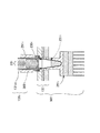
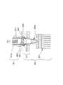
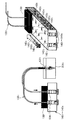
第1の発明は、2以上の各反応容器と直接的または間接的に連係可能であって、連係する該反応容器内部と光学的に接続する1または2以上の導光部の先端が設けられた2以上の連係部と、該各連係部に対応して設けられ、該連係部にその先端が設けられた導光部の後端が設けられた2以上の接続端を、所定経路に沿って配列して支持する配列面を有する接続端配列体と、前記配列面に近接若しくは接触して設けられ、該各接続端と前記所定経路に沿って順次光学的に接続可能な1または2以上の測定端を有し、該接続端と該測定端との光学的接続によって前記反応容器内の光学的状態に基づく光を受光可能な測定器と、前記接続端配列体に配列された前記各接続端と前記各測定端とを順次光学的に接続するように相対的に移動させる導光切換機構とを有する反応容器用光測定装置である。前記測定器が複数種類の測定器からなる場合には、各測定器に対して、少なくとも隣接する測定器間では、相互に異なる各所定周波数で各測定器が受光すべき光の強度を変調させる変調器と、該各測定器が受光した光に関して、前記各所定周波数に同調させて、対応する受光した光の強度を得る同調器とを有することが好ましい。 The first invention can be linked directly or indirectly to two or more reaction vessels, and is provided with one or more light guide tips that are optically connected to the associated reaction vessels. Two or more connecting portions, and two or more connecting ends provided corresponding to each of the connecting portions and provided with a rear end of a light guide portion provided at the leading end of the connecting portion, along a predetermined path. A connection end array having an array surface to be arranged and supported, and one or more connected to the array surface in close proximity or in contact with each other and sequentially optically connectable with each connection end along the predetermined path And a measuring device capable of receiving light based on the optical state in the reaction vessel by optical connection between the connection end and the measurement end, and each of the measuring ends arranged in the connection end array. A light guide switching mechanism for relatively moving the connection end and each of the measurement ends in order to optically connect them sequentially. It is the optical measuring device for reaction containers which has. When the measuring device comprises a plurality of types of measuring devices, the intensity of light to be received by each measuring device is modulated at a predetermined frequency different from each other at least between adjacent measuring devices. It is preferable to have a modulator and a tuner that tunes to each predetermined frequency with respect to the light received by each measuring device to obtain the intensity of the corresponding received light.
前記反応容器が設けられている容器群には、前記反応容器の他、検体、試薬等の液体を収容する2以上の液収容部を有するのが好ましい。また、容器群には、複数の液収容部としてのウェルがマトリクス状または列(行)状に配列されたマイクロプレートや複数の液収容部としてのウェルが列状に配列されたカートリッジ状容器を含む。核酸の増幅を行なう場合には、前記容器群には、例えば、検体、増幅対象である核酸またはその断片を捕獲可能な磁性粒子が懸濁した磁性粒子懸濁液、前記増幅対象の分離および抽出に用いる分離抽出用溶液、核酸増幅に用いる増幅用溶液を収容する2以上の液収容部を有することになる。
また、前記2以上の連係部は、導光用架台に配列して設けられるのが好ましい。In addition to the reaction container, the container group provided with the reaction container preferably has two or more liquid storage units for storing liquids such as specimens and reagents. In addition, the container group includes a microplate in which wells as a plurality of liquid storage portions are arranged in a matrix or a column (row), and a cartridge-like container in which wells as a plurality of liquid storage portions are arranged in a row. Including. When nucleic acid amplification is performed, the container group includes, for example, a specimen, a magnetic particle suspension in which magnetic particles capable of capturing a nucleic acid to be amplified or a fragment thereof are suspended, and separation and extraction of the amplification target. It has two or more liquid storage units for storing the separation / extraction solution used in the above and the amplification solution used for nucleic acid amplification.
Further, it is preferable that the two or more linking portions are arranged in a light guide base.
ここで、「増幅用溶液」とは、例えばPCR法による増幅を行なう場合には、増幅対象の鋳型DNA溶液、プライマ溶液、DNAポリメラーゼ溶液、ヌクレオチド溶液、反応バッファ溶液等であり、SPIA法による増幅を行う場合には、DNA/RNAキメラプライマ溶液、DNAポリメラーゼ溶液、RNaseH溶液等である。また、リアルタイムPCRでは、通常蛍光物質を含有する蛍光試薬を用いて行なう方法として、インターカレーション法、ハイブリダイゼーション法、およびLUX法がある。「インターカレーション法」は、SYBR(登録商標)GREEN I、エチジウムブロマイド 等の蛍光物質が伸長反応の際に、二本鎖DNAに入り込み、励起光の照射によって蛍光を発する特性を利用してDNA量を測定する方法である。したがって、増幅用溶液の中には、少なくとも、前記蛍光物質と、該蛍光物質の発光を抑制するクエンチャーを含有させることになる。「ハイブリダイゼーション法」は、PCRプライマに加え、蛍光物質で標識したDNAプローブを用いて目的のPCR産物だけを検出する方法である。すなわち、蛍光で標識したDNAプローブが目的のPCR産物にハイブリダイゼーションすることで、そのハイブリダイズしたDNA(量)が検出される。「LUX法」は、オリゴ核酸に標識した蛍光物質の蛍光シグナルが、そのオリゴ核酸の形状(配列や一本鎖または二本鎖等)によって影響される性質を利用したものである。実際のリアルタイムPCRでは、1種類の蛍光物質で標識化したPCRプライマ(LUXプライマ)とそれに対する何も標識化されていないPCRプライマを用いてリアルタイムPCRを行なう。そのLUXプライマは、蛍光物質を3'末端付近に標識してあり、5'末端との間でヘアピン構造をとるように設計されている。LUXプライマがヘアピン構造をとっている時は消光効果が解かれて蛍光シグナルが増大するようになる。このシグナル増大を測定することによって、PCR産物量を測定することができる。 Here, the “amplification solution” refers to a template DNA solution, a primer solution, a DNA polymerase solution, a nucleotide solution, a reaction buffer solution, etc. to be amplified when amplification is performed by PCR, for example, and amplification by SPIA In the case of performing DNA / RNA chimera primer solution, DNA polymerase solution, RNaseH solution and the like. In real-time PCR, there are an intercalation method, a hybridization method, and a LUX method as methods that are usually performed using a fluorescent reagent containing a fluorescent substance. The “intercalation method” uses the property that fluorescent substances such as SYBR (registered trademark) GREEN I and ethidium bromide enter double-stranded DNA during the extension reaction and emit fluorescence when irradiated with excitation light. It is a method of measuring quantity. Therefore, the amplification solution contains at least the fluorescent substance and a quencher that suppresses light emission of the fluorescent substance. The “hybridization method” is a method of detecting only a target PCR product using a DNA probe labeled with a fluorescent substance in addition to a PCR primer. That is, the hybridized DNA (amount) is detected by hybridization of the fluorescently labeled DNA probe with the target PCR product. The “LUX method” utilizes the property that the fluorescent signal of a fluorescent substance labeled on an oligonucleic acid is influenced by the shape (sequence, single strand, double strand, etc.) of the oligonucleic acid. In actual real-time PCR, real-time PCR is performed using a PCR primer (LUX primer) labeled with one type of fluorescent substance and a PCR primer not labeled with anything. The LUX primer has a fluorescent substance labeled near the 3 ′ end and is designed to take a hairpin structure with the 5 ′ end. When the LUX primer has a hairpin structure, the quenching effect is released and the fluorescence signal increases. By measuring this signal increase, the amount of PCR product can be measured.
前記反応容器を含む容器や蓋等の材料は、例えば、ポリエチレン、ポリプロピレン、ポリスチレン、アクリル等の樹脂、ガラス、金属、金属化合物等がある。容器のサイズは、例えば、数μリットルから数100μリットルの液体を収容可能であるとともに、分注チップの先端が挿入可能な大きさである。例えば、円筒状の場合には、例えば、1の容器の大きさの径が数ミリ〜数10ミリ、深さが数ミリ〜数10ミリである。 Examples of materials such as a container and a lid including the reaction container include resins such as polyethylene, polypropylene, polystyrene, and acrylic, glass, metal, and metal compounds. The size of the container is, for example, a size that can accommodate a liquid of several μl to several hundreds of μl and can be inserted into the tip of the dispensing tip. For example, in the case of a cylindrical shape, for example, the diameter of the size of one container is several millimeters to several tens of millimeters, and the depth is several millimeters to several tens of millimeters.
前記反応容器内は温度制御器によって温度制御が可能であるのが好ましい。
「温度制御器」は、温度制御の対象となる液体を収容する反応容器内の温度を、外部からの信号等に基づいて上昇または下降が可能な温度源を有するものであり、温度源としては、ブロック状部材に例えば、ペルチェ素子、ヒーター、冷却装置等を設けたものである。PCR等の処理を行なうには、温度制御器としては、ペルチェ素子を用いたサーマルサイクラが好ましい。すなわち、前記容器群またはステージには、温度源として、ペルチェ素子によって温度が昇降する温度制御用ブロックを、前記反応容器の一部(例えば、下側壁部分)または全体に接触または近接して設けることによって温度制御がなされるのが好ましい。また、LAMP法によるアイソサーマルな増幅の温度制御を行うことも可能である。It is preferable that the temperature inside the reaction vessel can be controlled by a temperature controller.
The “temperature controller” has a temperature source capable of raising or lowering the temperature in the reaction container containing the liquid to be temperature controlled based on an external signal or the like. The block-like member is provided with, for example, a Peltier element, a heater, a cooling device, and the like. In order to perform processing such as PCR, a thermal cycler using a Peltier element is preferable as the temperature controller. That is, the container group or stage is provided with a temperature control block whose temperature is raised or lowered by a Peltier element as a temperature source in contact with or close to a part (for example, the lower wall part) or the whole of the reaction container. It is preferable that the temperature is controlled by. It is also possible to perform isothermal amplification temperature control by the LAMP method.
「温度制御」とは、その対象となる液体または容器について、1または2以上の設定された所定温度に、設定された時間維持することを、定められた順序に従って、定められた回数実行することである。前記温度制御器への指示は、プログラムに基づいて該当する信号を送ることによってなされる。 “Temperature control” means that a target liquid or container is maintained at one or two or more set predetermined temperatures for a set time in accordance with a set order. It is. The temperature controller is instructed by sending a corresponding signal based on a program.
「所定温度」とは、対象となる液体等の物が到達すべき目標とする温度であり、例えば、前記液体に含有するDNA等の核酸や核酸の断片であるオリゴヌクレオチド等をPCR法によって増幅する場合には、設定される所定温度としては、例えば、PCR法で行なわれる温度サイクル、すなわち、DNAの変性、アニーリング若しくはハイブリダイゼーション、伸長に各々必要な各温度、約94℃、50℃から60℃の間の温度、および約72℃である。一方、SPIA法(商標)による場合には、一定温度、例えば、55℃等に設定されることになる。 The “predetermined temperature” is a target temperature to be reached by an object such as a target liquid. For example, a nucleic acid such as DNA contained in the liquid or an oligonucleotide that is a fragment of the nucleic acid is amplified by a PCR method. In this case, the predetermined temperature to be set is, for example, a temperature cycle performed by the PCR method, that is, each temperature necessary for DNA denaturation, annealing or hybridization, extension, about 94 ° C., 50 ° C. to 60 ° C. A temperature between 0 ° C and about 72 ° C. On the other hand, in the case of the SPIA method (trademark), it is set to a constant temperature, for example, 55 ° C.
さらに、該所定温度には、例えば、高温度の所定温度から低温度の所定温度への移行の場合に、温度制御器によって、これらの所定温度よりも低い移行促進用温度で冷却を行なうことで、または、低温度の所定温度から高温度の所定温度への移行の際に、これらの所定温度よりもさらに高い移行促進用温度で加熱を行なうことで、移行時間を短縮して1サイクル時間を所定サイクル時間内に収めるための移行促進用温度を含む。「所定時間」は、各温度の維持に必要な時間であって、増幅法の種類や、PCR法で用いる試薬や液量、ノズルの形状、素材、大きさ、厚さ等に依存するが、1サイクルで、合計が、例えば、数秒から数10秒、PCR法全体としての処理時間は、例えば、約数分から数10分程度である。なお、移行時間をも所定時間に含める。 In addition, for example, in the case of a transition from a high temperature predetermined temperature to a low temperature predetermined temperature, the predetermined temperature can be cooled by a temperature controller at a transition promoting temperature lower than these predetermined temperatures. Or, at the time of transition from a predetermined temperature of low temperature to a predetermined temperature of high temperature, heating is performed at a temperature for promoting transition higher than these predetermined temperatures, thereby shortening the transition time and reducing one cycle time. Includes transition-promoting temperature to keep within predetermined cycle time. "Predetermined time" is the time required to maintain each temperature, and depends on the type of amplification method, the reagent and liquid amount used in the PCR method, the shape, material, size, thickness, etc. of the nozzle, In one cycle, the total is, for example, several seconds to several tens of seconds, and the processing time of the entire PCR method is, for example, about several minutes to several tens of minutes. The transition time is also included in the predetermined time.
「連係部」は、前記反応容器と直接的または密閉蓋等を介して間接的に解除可能に連係可能な部材である。該連係部には前記反応容器内と光学的に接続して該反応容器内の光学的状態に基づく光を導光可能な導光部の先端が設けられている。ここで、「反応容器との連係」とは、反応容器の開口部、外壁、外底部または装着された密閉蓋や鞘等に近接しまたは連結することであって、「近接」は接触せずに導光部との間の光学的接続が可能な程度に接近することであり、「連結」には、接触、密接、密着、嵌合、装着を含み、導光部との間の光学的接続が可能なように少なくとも接触することである。この連係によって、連係部に設けられた導光部と反応容器内とが光学的に接続するためである。連係部としては、例えば、導光部が設けられた後述する導光用架台の板状部分である。「導光部」とは光が通過可能な光学系要素またはその組合せである。導光部の先端は、その板状部分に穿設された孔、光ファイバ等の透光性部分もしくはレンズ等の光学系要素またはその一端である。または、例えば、前記導光用架台から突出するように設けられた円筒状等の部材であって、導光部の先端は、該円筒状等の部材に設けられた空洞、光ファイバ等の透光性部分もしくはレンズ等の光学系要素またはその一端である。導光部としてその一部は可撓性がある場合が好ましい。この場合は、例えば、光ファイバまたは光ファイバ束若しくはこれらとレンズ等の光学要素との組合せである。蛍光を測定する場合には、2以上の導光部を有する場合があり、そのような場合にはその一部は照射用、他は受光用として用いることがある。なお、接続端は、これらの光学的要素またはその他端を有するものである。また、前記反応容器の開口部と直接的に連係する場合には、ミネラルオイル等を用いて反応容器内を密閉する場合であって、この場合には該連係部は該反応容器を直接的に密閉可能となるように形成するのが好ましい。また、開口部以外で連係する場合には、前記反応容器またはその連係部分は透光性をもつ必要がある。連係部の材質は、加熱部の熱が連係部を通って放熱しないようにPEEK材等の熱伝導率が低くかつ剛性のある樹脂で形成するのが、結露防止のために好ましい。また、加熱部の熱が連係部を通って放熱しない場合には、連係部に設けられた、光ファイバやレンズ等の光学系要素への熱の影響を防止することができる。好ましくは、前記接続端配列体の配列面 上の隣接する前記接続端の間隔は、導光用架台における隣接する前記連係部の間隔よりも小さくなるように形成する。これによって、連係部の配列に対して接続端の配列の集積化が可能となる。 The “linkage portion” is a member that can be releasably linked with the reaction vessel directly or indirectly via a sealing lid or the like. The linking portion is provided with a light guide tip that is optically connected to the inside of the reaction vessel and can guide light based on the optical state in the reaction vessel. Here, the term “linkage with the reaction vessel” means that it is close to or connected to the opening, outer wall, outer bottom of the reaction vessel, or the attached sealing lid or sheath, etc. The “connection” includes contact, close contact, close contact, fitting, and mounting, and includes optical contact with the light guide. At least contact so that a connection is possible. This is because the light guide portion provided in the linkage portion and the inside of the reaction vessel are optically connected by this linkage. As a connection part, it is the plate-shaped part of the light guide mount in which the light guide part was provided, for example. The “light guide” is an optical system element or a combination thereof through which light can pass. The tip of the light guide is a hole formed in the plate-like portion, a light-transmitting portion such as an optical fiber, an optical element such as a lens, or one end thereof. Alternatively, for example, a cylindrical member or the like provided so as to protrude from the light guide pedestal, and the distal end of the light guide portion is a cavity provided in the cylindrical member or the like, a transparent fiber such as an optical fiber. It is an optical system element such as an optical part or a lens, or one end thereof. It is preferable that a part of the light guide portion is flexible. In this case, for example, an optical fiber or an optical fiber bundle or a combination of these with an optical element such as a lens. When measuring fluorescence, it may have two or more light guides. In such a case, some of them may be used for irradiation and others for light reception. The connection end has these optical elements or other ends. Further, in the case of directly linking with the opening of the reaction vessel, the inside of the reaction vessel is sealed with mineral oil or the like. In this case, the linking portion directly connects the reaction vessel. It is preferable to form it so that it can be sealed. Moreover, when linking other than the opening, the reaction vessel or its linking portion needs to have translucency. The material of the linking part is preferably formed of a resin having low thermal conductivity and rigidity such as PEEK material so that the heat of the heating part does not radiate heat through the linking part. Further, when the heat of the heating part does not radiate heat through the linkage part, it is possible to prevent the influence of heat on the optical system elements such as optical fibers and lenses provided in the linkage part. Preferably, an interval between the adjacent connection ends on the arrangement surface of the connection end array is formed to be smaller than an interval between the adjacent linking portions in the light guide base. Thereby, it is possible to integrate the array of connection ends with respect to the array of linkage parts.
「所定経路」とは、前記測定端と前記接続端配列体とが相対的に移動することで、該測定端がそれに沿って配列された全接続端を走査可能な平面または曲面上の経路であって、全接続端を結ぶ経路が、1重または多重の交差しない線分(ジグザグ線、閉直線も含む)、曲線(螺旋、閉曲線も含む)、またはこれらの組み合わせ等に沿った経路である。好ましくは、1重または多重の各経路は、連続的で、尖点や角のないまっすぐな線分や、測定端が辿ることができる曲率を持つ滑らかな曲線に沿ったものが好ましい。 The “predetermined path” is a path on a plane or curved surface that allows the measurement end and the connection end array to move relative to each other so that all the connection ends arranged along the measurement end can be scanned. The path connecting all the connection ends is a path along a single or multiple non-intersecting line segments (including zigzag lines and closed lines), curves (including spirals and closed curves), or combinations thereof. . Preferably, each single or multiple path is continuous and is along a straight line without cusps or corners, or along a smooth curve with a curvature that can be traced by the measurement end.
前記連係部と接続端とは、1対1に対応する場合、複数対1に対応する場合、1対複数に対応する場合がある。これは、途中で、導光部が分岐または合流し、または複数の導光部からなる導光部束を分岐しまたは合流させることが可能である。 The linkage part and the connection end may correspond one-to-one, may correspond to a plurality of one-to-one, and may correspond to a one-to-multiple. In the middle of this, it is possible to branch or merge the light guide sections, or to branch or merge the light guide section bundle composed of a plurality of light guide sections.
該所定経路は、測定器の測定端の個数、形状、配置、またはサイズに基づいて、円滑な走査が可能なように定めるのが好ましい。例えば、接続端の測定端に対する移動において、急激な方向転換、例えば、進行方向に対し、鈍角的、直角的な方向への転換のない直線に沿った所定経路が好ましい。 The predetermined path is preferably determined so that smooth scanning is possible based on the number, shape, arrangement, or size of the measurement ends of the measuring device. For example, in the movement of the connection end with respect to the measurement end, a predetermined path along a straight line that does not change abruptly, for example, an obtuse or perpendicular direction with respect to the traveling direction, is preferable.
連係部の配列パターンは、例えば、行列状、列状または行状であり、接続端の配列パターンは、例えば、それと同一の配列、それとサイズのみ異なる相似の配列、または配列パターンが異なる場合、例えば、円形状、その他の閉曲線状、1列状若しくはより少ない列数または行数を持つような行列状の場合がある。配列された接続端を全て通過するように前記所定経路が定められる。接続端は、連係部に対して相互に移動可能に設けられる場合と、連係部に対して不動であって同じ光学的架台の連係部の配列面の反対側の接続端配列面に、接続端配列体として設けられる場合も含む。 The arrangement pattern of the linking portion is, for example, a matrix, a column, or a row, and the arrangement pattern of the connection ends is, for example, the same arrangement, a similar arrangement that differs only in size, or a different arrangement pattern, for example, There may be a circular shape, other closed curve shape, one column shape, or a matrix shape having a smaller number of columns or rows. The predetermined path is determined so as to pass through all the connection ends arranged. The connection end is provided so as to be movable with respect to the linkage portion, and to the connection end arrangement surface on the opposite side of the arrangement surface of the linkage portion of the same optical mount that is immovable with respect to the linkage portion. The case where it is provided as an array is also included.
さらに、前記接続端の配列は、前記連係部の配列に対して集積化されていることが好ましい。この場合には、導光部は可撓性をもつことが好ましい。「集積化」は、前記所定経路(または前記接続端の配列パターン)が、前記導光用架台の連係部の配列パターンを囲む領域面積または隣接する連係部間の間隔よりも小さい領域面積または小さい間隔であって、全走査距離を短くすることによって行なうのが好ましい。これによって速度を同一にした場合には、前記連係部を直接測定端が走査する場合よりも短い時間で処理可能である。また、空間的にも装置の規模が縮小されることになり、製造費用の削減や作業空間の有効利用に役に立つ。
例えば、「集積化」が、前記接続端配列体の配列面上の隣接する前記接続端の間隔は、導光用架台における隣接する前記連係部の間隔よりも小さくすることによって行われる場合には、例えば、複数の反応容器が、9mmピッチの間隔で配列されている場合であって、前記導光部の光ファイバの外径が1.5mmである場合には、接続端の配列のピッチを3.75mmに設定することができることを実験的に確認した。Furthermore, it is preferable that the arrangement of the connection ends is integrated with respect to the arrangement of the linkage portions. In this case, it is preferable that the light guide portion has flexibility. In “integration”, the predetermined path (or the array pattern of the connection ends) is smaller or smaller than the area of the region surrounding the array pattern of the link portions of the light guide base or the interval between adjacent link portions. Preferably, the interval is set to shorten the total scanning distance. Thus, when the speed is the same, it is possible to process in a shorter time than the case where the measurement end directly scans the linkage portion. In addition, the scale of the apparatus is reduced spatially, which is useful for reducing manufacturing costs and effectively using the work space.
For example, when “integration” is performed by making the interval between the adjacent connection ends on the arrangement surface of the connection end array smaller than the interval between the adjacent linking portions in the light guide base For example, when a plurality of reaction vessels are arranged at intervals of 9 mm and the outer diameter of the optical fiber of the light guide is 1.5 mm, the pitch of the arrangement of the connection ends is 3.75. It was confirmed experimentally that it can be set to mm.
集積化の程度は、高ければ高いほど処理時間が短縮され、かつ空間的に装置規模が圧縮されて好ましいが、少なくとも、前記接続端配列体と前記測定器との間の相対的な移動または走査が、安定的受光可能時間内に測定すべき全反応容器からの受光を完了することができる程度以下であることが好ましい。ここで、「安定的受光可能時間」とは、反応容器内の受光可能な光学的状態が安定的に維持される時間であって、例えば、リアルタイムPCRのインターカレーション法やLUX法またはハイブリダイゼーション法のTaqManプローブの場合には、PCRの各サイクルの伸長反応が行われる時間がこれに相当する。なお、ハイブリダイゼーション法でFRETプローブを用いる場合はアニーリングが行われる時間がこれに相当する。 The higher the degree of integration, the shorter the processing time and the smaller the apparatus size, which is preferable, but at least the relative movement or scanning between the connection end array and the measuring instrument. However, it is preferable to be less than or equal to the extent that the light reception from all the reaction containers to be measured within the stable light reception time can be completed. Here, the “stable light receiving time” is a time during which the optical state capable of receiving light in the reaction container is stably maintained. For example, a real-time PCR intercalation method, LUX method or hybridization In the case of the TaqMan probe of the method, this corresponds to the time during which the extension reaction of each cycle of PCR is performed. In the case of using a FRET probe in the hybridization method, the time for annealing is equivalent to this.
これによって、安定的受光可能時間が短い発光体等に対しても適用することができるので汎用性が高い。 As a result, the present invention can be applied to a light-emitting body or the like having a short stable light receiving time, so that versatility is high.
1サイクルにかかる時間が例えば、数10秒から数分とすると、この安定的受光可能時間は、例えば、数秒から10秒程度ということになる。但し、PCR反応の初期のサイクルでは蛍光検出量は検出限界以下であり、PCR反応の後期のサイクルはプラトー状態になり厳密な意味で定量性を確保するには、指数関数的なPCR増幅が観察できる増幅曲線の範囲内ということになる。本発明は、安定的受光可能時間が、測定端の反応容器間の移動時間に用いることができることを利用して、各反応容器からの光の受光に必要な相対的な移動をこの安定的受光可能時間内に行うことで、複数の反応容器からの受光を、複雑な光学系要素を用いることなく、かつ装置規模を拡大することなく反応容器数に比較して十分に少ない個数もしくは1の測定器により、ほぼ並行して行なうことができるものである。 If the time required for one cycle is, for example, several tens of seconds to several minutes, this stable light receiving time is, for example, about several seconds to 10 seconds. However, the amount of fluorescence detected is below the detection limit in the initial cycle of the PCR reaction, and the latter cycle of the PCR reaction is in a plateau state, and in order to ensure quantification in a strict sense, exponential PCR amplification is observed. This is within the range of the amplification curve that can be produced. The present invention makes use of the fact that the stable light reception time can be used as the movement time between the reaction vessels at the measurement end, and the relative movement necessary for receiving the light from each reaction vessel is represented by this stable light reception. By performing within the possible time, light reception from a plurality of reaction vessels can be performed in a sufficiently small number or 1 compared with the number of reaction vessels without using complicated optical system elements and without increasing the scale of the apparatus. It can be performed almost in parallel by the vessel.
「光学的状態」とは、発光、呈色、変色または変光等の状態である。光学的状態に基づく光とは、発光もしくは変光による光、呈色もしくは変色に対し照射した光の反射光もしくは透過光、散乱光等である。 The “optical state” is a state such as light emission, coloration, color change, or light change. The light based on the optical state is light generated by light emission or change, reflected light or transmitted light of light applied to coloration or color change, scattered light, or the like.
「前記各接続端と前記測定端とを順次光学的に接続する」とは、前記接続端と前記測定端とが、至近距離で向かい合うことで光学的に接続させることである。接続の瞬間は、前記測定器が受光する光量の極大値に相当するので、前記測定制御部は、該光量の極大値を算出することで測定すべきデータを特定することになる。 “To optically connect each connection end and the measurement end sequentially” means that the connection end and the measurement end are optically connected by facing each other at a close distance. Since the moment of connection corresponds to the maximum value of the amount of light received by the measuring instrument, the measurement control unit specifies data to be measured by calculating the maximum value of the amount of light.
「測定器」は、例えば、蛍光、化学発光の測定を可能にするものであって、前者の場合には、1または2以上の種類の励起光の照射、1または2以上の種類の波長をもつ蛍光の受光、そのためのフィルタを有する。これらを光ファイバを用いて導光することが好ましい。また、複数種類の測定器には、波長(または周波数)の大きさや範囲に対応して設けられた場合がある。 The “measuring device” enables measurement of, for example, fluorescence and chemiluminescence. In the former case, irradiation of one or more types of excitation light, one or more types of wavelengths are performed. Fluorescent light reception and a filter for this purpose. These are preferably guided using an optical fiber. In addition, a plurality of types of measuring devices may be provided corresponding to the size or range of wavelengths (or frequencies).
「測定端」は、前記測定器に設けられた受光すべき光の入射口を少なくとも有し、蛍光の測定の場合には照射すべき光の出射口を有する。これらは、別の測定端として設けることができる。なお前記入射口または出射口は、内部に設けた光電素子からなる受光部または照射源と光学的に接続する。その際、各々受光用の導光部または照射用の導光部を介して接続することができる。また、前記接続端配列体、測定端、測定器は、加熱制御や温度制御の行われる反応容器や装着用架台と直接的に接触したり近接しないような離れた位置に設けるのが好ましい。 The “measurement end” has at least an incident port for light to be received provided in the measuring instrument, and has an exit port for light to be irradiated in the case of fluorescence measurement. These can be provided as separate measuring ends. The entrance or exit is optically connected to a light receiving unit or irradiation source made of a photoelectric element provided inside. In that case, it can each connect via the light guide part for light reception, or the light guide part for irradiation. Further, it is preferable that the connection end array, the measurement end, and the measuring device are provided at positions that are not in direct contact with or close to a reaction vessel or a mounting base on which heating control or temperature control is performed.
なお、前記反応容器用光測定装置には、その他、明示していないが「測定制御部」を有し、「測定制御部」は、前記測定器および導光切換機構を制御し、前記反応容器用光測定装置に内蔵したコンピュータ(CPU)および該コンピュータを駆動するプログラムからなり、例えば、DA変換器を通して信号を前記移動機構を駆動する各制御部に送ることによって測定制御がなされることになる。 The reaction vessel optical measurement device has a “measurement control unit” which is not explicitly described, and the “measurement control unit” controls the measuring device and the light guide switching mechanism, and the reaction vessel A computer (CPU) built in the optical measuring device and a program for driving the computer. For example, measurement control is performed by sending a signal to each control unit for driving the moving mechanism through a DA converter. .
ここで、「変調器」とは、各測定器が受光すべき光の強度を所定周波数で変調させる装置である。例えば、反応容器内の光学的状態が蛍光の発光である場合には、後述する励起光変調部を有する。該励起光変調部は、蛍光物質に照射する励起光を発生させるための照射源に印加する電圧を、前記所定周波数を持つ振動電圧とする振動電圧供給回路等の駆動回路や、前記所定周波数で受光すべき光を点滅させるための種々の装置、例えば、光シャッター、回転するポリゴンミラー、有透光孔回転体による光チョッパーを含む。「所定周波数の振動電圧」には、正弦波的な振動、光の点滅を含むパルス波的な変動がある。「同調器」は、受光した光に関して、前記所定周波数に同調することによって、対応する受光した光の光強度を得る装置であって、例えば、前記周波数または周波数帯域を取り出す帯域通過フィルタ回路を有する。これは、一般に、励起光の波長は蛍光の波長よりも短かく、かつ強度が高いので、複数種類の蛍光を、複数種類の励起光を用いて、互いに接近させた状態で測定を行なうことがありうる。このような場合に、ある励起光の波長と蛍光の波長が重なると、蛍光を励起光から抽出することが困難になるからである。そこで、少なくとも隣接する測定器間では、異なる所定周波数で変調させることで両者を区別することができることになる。これによって自然光等の他の雑光を排除することができることになる。
なお、「所定周波数」としては、1Hzから1MHzの間、好ましくは、1kHzから10kHz程度である。「少なくとも隣接する測定器間」であるので、一定の距離以上離れた測定器間の場合には、同一の周波数を用いることが可能である。Here, the “modulator” is a device that modulates the intensity of light to be received by each measuring device at a predetermined frequency. For example, when the optical state in the reaction vessel is fluorescence emission, an excitation light modulation unit described later is included. The excitation light modulation unit includes a drive circuit such as an oscillating voltage supply circuit that uses an oscillating voltage having the predetermined frequency as a voltage applied to an irradiation source for generating excitation light that irradiates the fluorescent material, and the predetermined frequency. Various devices for blinking light to be received, for example, an optical shutter, a rotating polygon mirror, and a light chopper by a transparent hole rotating body. The “vibration voltage having a predetermined frequency” includes pulse wave fluctuations including sinusoidal vibrations and blinking of light. The “tuner” is a device that obtains the light intensity of the corresponding received light by tuning to the predetermined frequency with respect to the received light, and has, for example, a band-pass filter circuit that extracts the frequency or frequency band. . In general, the wavelength of the excitation light is shorter than the wavelength of the fluorescence and the intensity thereof is high, so that it is possible to measure a plurality of types of fluorescence in a state where they are close to each other using a plurality of types of excitation light. It is possible. This is because in such a case, if the wavelength of a certain excitation light and the wavelength of the fluorescence overlap, it becomes difficult to extract the fluorescence from the excitation light. Therefore, at least between adjacent measuring instruments can be distinguished by modulating them at different predetermined frequencies. As a result, other miscellaneous light such as natural light can be eliminated.
The “predetermined frequency” is between 1 Hz and 1 MHz, preferably about 1 kHz to 10 kHz. Since it is “at least between adjacent measuring devices”, it is possible to use the same frequency in the case of measuring devices separated by a certain distance or more.
第2の発明は、前記測定器による受光の際には、少なくとも前記測定端を除く測定器本体は該反応容器およびそれに連係した連係部を有する前記導光用架台に対して不動に設けられている反応容器用光測定装置である。
したがって、前記接続端配列体が前記測定端に対し移動し、または測定端が前記接続端配列体に対して移動する場合があり、前記測定器本体は前記反応容器に前記導光用架台が連係するまでは、前記反応容器または前記導光用架台に対して移動可能に設けられて良い。前者の場合は、例えば、測定器本体が前記導光用架台と連動する場合または一部方向の移動に連動する場合であり、後者の場合は、測定器本体が前記反応容器と連動し、または反応容器とともにステージに固定されている場合である。なお、測定端には、もし存在する場合には測定器本体の外にあって測定端までの導光部をも含む。According to a second aspect of the present invention, at the time of light reception by the measuring device, at least the measuring device main body excluding the measuring end is provided immovably with respect to the reaction vessel and the light guide mount having a linking portion linked thereto. The reaction vessel optical measurement device.
Therefore, the connection end array may move with respect to the measurement end, or the measurement end may move with respect to the connection end array, and the measuring instrument body is linked to the reaction vessel with the light guide base Until then, it may be provided so as to be movable with respect to the reaction vessel or the light guide base. In the former case, for example, when the measuring instrument main body is interlocked with the light guide base or when the measuring instrument main body is interlocked with movement in a part of the direction, the latter case is interlocked with the reaction container, or This is a case where the reaction vessel and the stage are fixed. It should be noted that the measurement end also includes a light guide portion that is outside the measuring instrument main body and extends to the measurement end if present.
第3の発明は、前記測定器は、特定波長または特定波長帯の光を受光可能な複数種類の特定波長測定器からなり、各特定波長測定器は、前記各接続端と前記所定経路に沿って順次光学的に接続可能な少なくとも1の測定端を有し、前記各特定波長測定器に設けられた前記変調器の前記周波数は、少なくとも隣接する所定特定波長測定器間において、相互に異なり、前記光学的状態に基づく光が蛍光の場合には、各特定波長測定器は、対応する特定波長または特定波長帯の蛍光を励起する所定励起光を照射する照射源と、前記特定波長または特定波長帯の蛍光を受光可能な受光部とを有し、前記各特定波長測定器に対応する前記各変調器は、前記所定周波数で各所定励起光を変調させる励起光変調部を有し、前記各同調器は、前記受光部が受光した光について、前記各所定周波数をもつ光の強度データを抽出する帯域通過フィルタ回路またはロックインアンプを有する反応容器用光測定装置である。 According to a third aspect of the present invention, the measuring device includes a plurality of types of specific wavelength measuring devices capable of receiving light of a specific wavelength or a specific wavelength band, and each specific wavelength measuring device is along the connection end and the predetermined path. And at least one measurement end that can be optically connected sequentially, and the frequency of the modulator provided in each specific wavelength measuring device is different from each other at least between predetermined specific wavelength measuring devices adjacent to each other, When the light based on the optical state is fluorescence, each specific wavelength measuring device includes an irradiation source that irradiates predetermined excitation light that excites fluorescence of a corresponding specific wavelength or specific wavelength band, and the specific wavelength or specific wavelength. Each of the modulators corresponding to each of the specific wavelength measuring devices has an excitation light modulation unit that modulates each predetermined excitation light at the predetermined frequency, and The tuner receives light from the light receiver. For light, the a reaction vessel optical measuring device having a band pass filter circuit or the lock-in amplifier for extracting intensity data of light having a respective predetermined frequency.
ここで、測定端には、例えば、空洞、レンズ等の光学系要素、光ファイバ等の導光部が設けられることになる。また、各測定端には、前記照射源と接続する照射口、受光部と接続する受光口を有する。「帯域通過フィルタ回路」とは、測定対象の信号から(変調した)前記所定周波数を含む周波数帯域をもつ光の信号のみを抽出しそれ以外の周波数の信号を除去する回路であり、ハイパスフィルタとローパスフィルタを組み合わせたフィルタ回路が例示され、「ロックインアンプ」とは、測定対象の信号と、変調した前記所定周波数を持つ参照信号の2つを乗算器(Phase Sensitive Detector)で乗算し、その後平滑化して前記所定周波数を持つ信号の強度成分をもつ出力信号を得る回路である。 Here, for example, a cavity, an optical system element such as a lens, and a light guide unit such as an optical fiber are provided. Each measurement end has an irradiation port connected to the irradiation source and a light receiving port connected to the light receiving unit. The “band-pass filter circuit” is a circuit that extracts only a light signal having a frequency band including the predetermined frequency (modulated) from a signal to be measured, and removes signals of other frequencies. A filter circuit that combines a low-pass filter is exemplified. A “lock-in amplifier” is a product of a signal to be measured and a modulated reference signal having the predetermined frequency multiplied by a multiplier (Phase Sensitive Detector), and then It is a circuit that obtains an output signal having the intensity component of the signal having the predetermined frequency by smoothing.
第4の発明は、2以上の前記連係部は導光用架台に設けられ、前記連係部が2以上の前記反応容器と一斉に直接的又は間接的に連係するように前記導光用架台を前記反応容器に対して相対的に移動する架台移動機構を有する反応容器用光測定装置である。 According to a fourth aspect of the present invention, two or more linkage parts are provided on a light guide base, and the light guide base is arranged so that the linkage parts are directly or indirectly linked to two or more reaction vessels simultaneously. It is the optical measurement apparatus for reaction containers which has the mount movement mechanism which moves relatively with respect to the said reaction container.
好ましくは、前記接続端配列体の配列面上の隣接する前記接続端の間隔は、導光用架台における隣接する前記連係部の間隔よりも小さくなるように形成する。
前記架台移動機構は前記導光用架台を前記容器群に対して上下方向に相対的に移動可能とする場合には、前記反応容器の開口部を被覆するように装着された密閉蓋を押圧または振盪することができる。すなわち、前記測定制御部は、前記反応容器の開口部を被覆するように密閉蓋を介して前記連係部と間接的に連係した後、該密閉蓋を押圧または振盪するように制御することが好ましい。押圧によって、反応容器の密閉を確実にすることができるとともに、振盪によって、反応容器の開口部と密閉蓋との間の密閉状態を迅速かつ容易に解除し開放することができる。したがって、高い処理効率および信頼性を得ることができる。Preferably, the interval between the adjacent connection ends on the arrangement surface of the connection end array is formed to be smaller than the interval between the adjacent linkage portions in the light guide base.
When the gantry moving mechanism is configured to move the light guide gantry relatively in the vertical direction with respect to the container group, the gantry moving mechanism presses the sealing lid mounted to cover the opening of the reaction container or Can be shaken. That is, it is preferable that the measurement control unit performs control so that the sealing lid is pressed or shaken after being indirectly linked with the linking portion via the sealing lid so as to cover the opening of the reaction vessel. . By pressing, the reaction vessel can be securely sealed, and by shaking, the sealed state between the opening of the reaction vessel and the sealing lid can be quickly and easily released and opened. Therefore, high processing efficiency and reliability can be obtained.
なお、連係部が前記反応容器の開口部と直接的または間接的に嵌合等の連結によってではなく、反応容器に近接することで反応容器と連係する場合には、上下方向の相対的な移動を行なうことなく水平方向の移動によって、連係部と反応容器との間の連係とその解除を順次円滑に繰り返すことができる。 When the linking part is linked to the reaction container by being close to the reaction container, not directly or indirectly by connection such as fitting with the opening of the reaction container, the relative movement in the vertical direction By moving in the horizontal direction without performing the steps, the linkage between the linkage portion and the reaction vessel and the release thereof can be sequentially and smoothly repeated.
また、前記導光用架台に設けられた2以上の連係部は、2以上の反応容器と直接的または間接的に一斉に連係可能な状態で該導光用架台に対して水平方向に移動可能な連係部配列体に配列され、該連係部配列体を前記導光用架台に対して移動することによって、前記導光用架台を移動することなく該連係部配列体により一斉に連係可能な反応容器数よりも多い反応容器と連係可能とする反応容器用光測定装置を提供することができる。この場合には、各連係部と反応容器との連係を、各連係部が挿入可能であってその連係部配列体が移動可能な水平方向に延びるとともに該導光用架台に前記連係部ごとに設けた2以上の溝内または相互に隔壁で仕切られた2以上の領域等の相互に遮蔽された遮蔽領域内で行なうことが好ましい。これによって、他の反応容器からの光の混入を確実に防止することができる。 Further, two or more linking portions provided on the light guide pedestal can move in a horizontal direction with respect to the light guide pedestal in a state in which the two or more reaction vessels can be directly or indirectly linked together. A reaction that can be linked together by the linkage portion array without moving the light guide mount by moving the link portion array relative to the light guide mount. It is possible to provide a light measuring device for a reaction container that can be linked to more reaction containers than the number of containers. In this case, the linkage between each linkage portion and the reaction vessel is extended in the horizontal direction in which each linkage portion can be inserted and the linkage portion array body is movable, and the light guide base is attached to each linkage portion. It is preferable to carry out in two or more grooves provided or in a shielded area shielded from each other such as two or more areas partitioned by a partition wall. Thereby, mixing of light from other reaction containers can be surely prevented.
この場合には、前記連係部は、前記導光用架台の上下方向の移動によらずに、水平方向に移動するだけで容易かつ高速に反応容器と連係させることができる。したがって、連係部配列体の水平方向の移動を含めて前記安定的受光可能時間内に行なうことができるように連係部配列体の速度を設定することによって、より一層多数の反応容器について、1組の測定器によって、ほぼ並行して受光および測定を行なうことができる。 In this case, the linking part can be easily and rapidly linked to the reaction vessel simply by moving in the horizontal direction without depending on the vertical movement of the light guide base. Accordingly, by setting the speed of the linking portion array so that it can be performed within the stable light receiving time including the horizontal movement of the linking portion array, one set of more reaction vessels can be obtained. With this measuring device, light reception and measurement can be performed substantially in parallel.
なお、前記測定器が、前記各接続端と光学的に接続可能な1または2以上の測定端を有し特定波長又は特定波長帯の光を受光可能な複数種類の特定波長測定器を有する場合には、前記所定経路に沿って前記各接続端と光学的に接続可能なように複数の前記各測定端を整列させる測定端整列部とを有するのが好ましい。 When the measuring device has one or more measuring ends that can be optically connected to each of the connecting ends, and has a plurality of types of specific wavelength measuring devices that can receive light of a specific wavelength or a specific wavelength band. It is preferable to have a measurement end alignment section that aligns the plurality of measurement ends so that they can be optically connected to the connection ends along the predetermined path.
「整列」は、一体的または連鎖的に行われる。「一体的」とは、前記測定端間が自由度なしで相互に固定されるように配列されること。「連鎖的」とは、前記測定端間が鎖のようにある程度の自由度をもって配列されることである。「整列」は、前記所定経路の走査方向または走査方向に垂直な方向に沿って各測定端が並ぶ場合がある。後者の場合には、所定経路としては、複数の経路が並列的に並ぶことになる。 “Alignment” is performed integrally or in a chain. “Integrally” means that the measurement ends are arranged to be fixed to each other without any degree of freedom. “Chain” means that the measurement ends are arranged with a certain degree of freedom like a chain. In “alignment”, the measurement ends may be arranged along the scanning direction of the predetermined path or a direction perpendicular to the scanning direction. In the latter case, a plurality of paths are arranged in parallel as the predetermined path.
本発明によれば、複数種類の発光物質、呈色物質、変色物質または変光物質を用いることで、複数種類の増幅対象を1の反応容器で、同一条件で並行に増幅処理することで、複数種類の増幅対象について、複数種類の発光物質等で標識化したプライマを用いること等によって多重PCR増幅や多重リアルタイムPCRを行なうことが可能である。 According to the present invention, by using a plurality of types of luminescent materials, color developing materials, color changing materials or light changing materials, a plurality of types of amplification targets can be amplified in parallel under the same conditions in one reaction vessel, For a plurality of types of amplification targets, multiplex PCR amplification or multiplex real-time PCR can be performed by using a primer labeled with a plurality of types of luminescent substances or the like.
「特定波長または特定波長帯の光」であるから、例えば、可視光でいえば、赤色、黄色、緑色、青色、紫色等の波長の範囲である。 Since it is “light of a specific wavelength or a specific wavelength band”, for example, in the case of visible light, it is a range of wavelengths such as red, yellow, green, blue, and purple.
第5の発明は、前記容器群には、1または2以上の前記反応容器の開口部に装着されて該反応容器を密閉する透光性を有する密閉蓋を有する反応容器用光測定装置である。 A fifth aspect of the present invention is a reaction container photometric device having a translucent sealing lid attached to the opening of one or more of the reaction containers and sealing the reaction containers in the container group. .
ここで、「密閉蓋」には、板状またはブロック状の非可撓性のものの他、柔軟性のあるフィルム状または膜状のものも含む。前記「装着」には、嵌合、螺合、摩擦、吸着、付着、接着等が含まれる。この場合、着脱可能に装着するのが好ましい。 Here, the “sealing lid” includes not only a plate-like or block-like inflexible but also a flexible film-like or film-like one. The “mounting” includes fitting, screwing, friction, adsorption, adhesion, adhesion, and the like. In this case, it is preferable to detachably attach.
また、前記導光用架台の各連係部を各反応容器の開口部において連係させた場合には、前記反応容器の開口部を被覆する密閉蓋に対して、前記連係部またはノズルを押圧または振盪可能とするのが好ましい。 In addition, when each linking portion of the light guide base is linked at the opening of each reaction vessel, the linking portion or the nozzle is pressed or shaken against the sealing lid that covers the opening of the reaction vessel. Preferably it is possible.
前記連係部は前記導光用架台の下方に突出するように設けられるのが好ましい。この場合、連係部は、例えば、棒状、筒状、錐状等の形状をもち、該部材の下端部が前記密閉蓋と接触可能であるのが好ましい。 It is preferable that the linkage portion is provided so as to protrude below the light guide base. In this case, it is preferable that the linkage portion has a shape such as a rod shape, a cylindrical shape, or a cone shape, and the lower end portion of the member can contact the sealing lid.
前記密閉蓋は、1個で1または2以上の反応容器の開口部を被覆する。密閉蓋は、例えば、後述するノズルに装着させて移動し、チップ脱着機構を用いて反応容器の開口部を被覆させることになる。そのためには、密閉蓋の上側には、1または2以上の前記ノズルに装着可能な1または2以上の装着用の窪みが設けられることになる。1または2以上の前記連係部は、前記導光用架台の上下方向の移動によってこの窪み(連係用の窪みでもある)内に挿入されて反応容器と連係させることができる。 One sealing lid covers the openings of one or more reaction vessels. For example, the sealing lid is moved by being attached to a nozzle to be described later, and covers the opening of the reaction vessel using a chip detachment mechanism. For this purpose, one or more mounting recesses that can be mounted on one or more of the nozzles are provided on the upper side of the sealing lid. One or two or more of the linking portions can be inserted into the dent (which is also a dent for linking) by the vertical movement of the light guide base and linked to the reaction vessel.
密閉蓋をノズルにより移動せずに、専用の密閉蓋搬送機構を設けることもできる。該密閉蓋搬送機構として、前記反応容器用光測定装置は、例えば、前記容器群に対して移動可能な搬送体と、各反応容器の開口部を被覆する被覆板、および光が透過可能な該被覆板の中央部を除く部分で下側に突出して前記反応容器に前記被覆板を装着可能な装着部を有する密閉蓋について、前記装着部が前記反応容器に装着可能な状態で下側に露出するように前記被覆板を把持し、前記反応容器の配列に応じて前記搬送体に配列された1または2以上の把持部とを有する密閉蓋搬送体を有するものである。また、密閉蓋搬送体は、前記導光用架台と連動させるようにすれば、装置構造を簡素化し、装置規模の拡大を防ぐことができる。 A dedicated sealing lid transport mechanism can also be provided without moving the sealing lid by the nozzle. As the sealing lid transport mechanism, the reaction container optical measurement device includes, for example, a transport body movable with respect to the container group, a covering plate that covers the opening of each reaction container, and the light transmissive member. A sealing lid having a mounting portion that protrudes downward at a portion excluding the central portion of the covering plate and that can mount the covering plate on the reaction vessel, and is exposed to the lower side in a state where the mounting portion can be mounted on the reaction vessel. The cover plate is gripped as described above, and has a hermetic lid transport body having one or more grip portions arranged on the transport body in accordance with the arrangement of the reaction containers. Further, if the hermetic lid carrier is interlocked with the light guide base, the structure of the apparatus can be simplified and the scale of the apparatus can be prevented from being increased.
この場合には、密閉蓋の上側には、ノズル装着用等の窪みを設ける必要がないので、前記連係部は、前記導光用架台の上下方向の移動によらずに、密閉蓋上で反応容器の開口部間を水平方向に移動するだけで容易に連係させることができる。この場合、連係部の水平方向の移動を前記安定的受光可能時間内に行なうことができれば、より一層多数の反応容器について、ほぼ並行して受光および測定が可能となる。 In this case, since it is not necessary to provide a recess for mounting a nozzle or the like on the upper side of the sealing lid, the linking portion reacts on the sealing lid without depending on the vertical movement of the light guide base. It can be easily linked only by moving horizontally between the openings of the container. In this case, if the linking portion can be moved in the horizontal direction within the time during which stable light reception is possible, light reception and measurement can be performed in parallel in a larger number of reaction vessels.
第6の発明は前記導光用架台には、前記密閉蓋を加熱可能な加熱部を有する反応容器用光測定装置である。 A sixth aspect of the present invention is the reaction container optical measurement device, wherein the light guide base has a heating unit capable of heating the sealing lid.
例えば、前記測定制御部は、前記連係部に前記密閉蓋を一斉に装着した後に、前記光学的連係部が2以上の反応容器と一斉に間接的に連係するように前記架台移動機構を制御した後、前記密閉蓋を加熱するように前記加熱部を制御する。「加熱部」は、例えば、加える電流の大きさによってまたはオン・オフ制御に基づいて設定される温度での加熱機能を有する。 For example, the measurement control unit controls the gantry moving mechanism so that the optical linking unit is indirectly linked to two or more reaction vessels simultaneously after the sealing lids are attached to the linking unit all at once. Thereafter, the heating unit is controlled to heat the sealing lid. The “heating unit” has a heating function at a temperature set by, for example, the magnitude of an applied current or based on on / off control.
ここで、該加熱部による密閉蓋の加熱は、前記密閉蓋が密閉した前記反応容器の温度制御の際の結露防止のために行う。 Here, the heating of the sealing lid by the heating unit is performed to prevent condensation during temperature control of the reaction vessel sealed by the sealing lid.
第7の発明は、前記反応容器の下側壁部分に接触または近接して設けられた温度源を有する温度制御器と、前記反応容器の該下側壁部分よりも上側に位置した前記反応容器の上側壁部分に接触または近接して設けられて、該上側壁部分を加熱可能な加熱源を有する加熱部とを有する反応容器用光測定装置である。 According to a seventh aspect of the present invention, there is provided a temperature controller having a temperature source provided in contact with or close to a lower wall portion of the reaction vessel, and an upper portion of the reaction vessel positioned above the lower wall portion of the reaction vessel. A reaction container optical measurement device having a heating unit provided with a heating source provided in contact with or in proximity to the side wall portion and capable of heating the upper side wall portion.
ここで、「下側壁部分」は、反応容器の全容量の一部(例えば、1%から90%)の予め定めた所定液量が収容可能な容量部分を囲み底部を含む壁部分またはその一部である。該下側壁部分は、例えば、前記規定液量の液体を収容可能な部分の壁部分である。例えば、前記連係部と連係する広口管部および細口管部からなる反応容器の場合には、細口管部に設けられる。「上側壁部分」は、反応容器の全容量の内、前記規定液量が収容された下側容器部分の残りの容量を囲む容器部分またはその一部である。「上側壁部分」は、通常、前記下側壁部分と間隔を空けた反応容器の上側に設けられるのが好ましい。上側壁部分は、下側壁部分よりも開口部、密閉蓋、または連係部に近いことになる。例えば、前記広口管部および前記細口管部からなる容器の場合で、連係部が広口管部と嵌合することで連係する場合には、広口管部の壁部分に上側壁部分が設けられる。上側壁部分は、例えば、該容器壁の周に沿った帯状に相当する部分である。 Here, the “lower wall portion” is a wall portion including a bottom portion or a part of the wall portion that surrounds a volume portion that can accommodate a predetermined predetermined liquid amount of a part (for example, 1% to 90%) of the total volume of the reaction vessel. Part. The lower wall portion is, for example, a wall portion of a portion that can accommodate the liquid of the specified liquid amount. For example, in the case of a reaction vessel composed of a wide-mouthed pipe part and a narrow-mouthed pipe part linked to the linkage part, it is provided in the narrow-mouthed pipe part. The “upper wall portion” is a container portion that surrounds the remaining volume of the lower container portion in which the specified liquid amount is accommodated, or a part thereof, out of the total capacity of the reaction vessel. The “upper wall portion” is usually preferably provided on the upper side of the reaction vessel spaced from the lower wall portion. The upper wall portion is closer to the opening, the sealing lid, or the linkage portion than the lower wall portion. For example, in the case of a container composed of the wide-mouthed tube portion and the narrow-mouthed tube portion, when the linking portion is linked by fitting with the wide-mouthed tube portion, an upper wall portion is provided on the wall portion of the wide-mouthed tube portion. The upper side wall portion is, for example, a portion corresponding to a strip shape along the circumference of the container wall.
前記測定制御部は、前記連係部が反応容器と一斉に直接的または間接的に連係するように架台移動機構を制御した後に、前記連係部の直接的または間接的な結露を防止するように前記加熱部を制御する。「間接的な連係」とは、密閉蓋、反応容器の外壁等を介して前記連係部が反応容器と連係する場合である。「加熱部の制御」は、結露防止のために「温度制御」に応じて行われる。例えば、加熱温度は、温度制御で設定された各所定温度よりも、数度(結露防止に必要な水蒸気の露点を超える温度)から数10℃(反応容器の素材の融点よりは十分に低い温度)、例えば、1℃から60℃、好ましくは、約5℃程度高めに設定するように制御する。例えば、増幅がPCRの場合には、94℃から数度高い温度、例えば、100℃で加熱し、アイソサーマルの場合には、所定温度が約55℃の場合には、例えば、それより数度高い温度、例えば、60℃から70℃程度で加熱される。なお、加熱温度は、温度制御の対象となる液量や、配列された反応容器の位置にも依存する。例えば、実験によると、温度制御で設定された温度が95℃の場合、液量25μLでは、113℃で結露が消失した。 The measurement control unit controls the gantry moving mechanism so that the linking unit is directly or indirectly linked to the reaction vessel at once, and then prevents the linking unit from directly or indirectly condensing. Control the heating section. “Indirect linkage” refers to the case where the linkage portion is linked to the reaction vessel via a sealing lid, the outer wall of the reaction vessel, or the like. “Control of the heating unit” is performed according to “temperature control” in order to prevent condensation. For example, the heating temperature is several degrees (a temperature exceeding the dew point of water vapor necessary for preventing condensation) to several tens of degrees Celsius (a temperature sufficiently lower than the melting point of the material in the reaction vessel) than each predetermined temperature set by temperature control. ), For example, 1 to 60 ° C., preferably about 5 ° C. higher. For example, when amplification is PCR, heating is performed at a temperature higher than 94 ° C., for example, 100 ° C., and when isothermal is used, when the predetermined temperature is about 55 ° C., for example, several degrees higher than that. Heating is performed at a high temperature, for example, about 60 ° C to 70 ° C. The heating temperature also depends on the amount of liquid to be temperature controlled and the position of the arranged reaction vessels. For example, according to experiments, when the temperature set by the temperature control is 95 ° C., the condensation disappeared at 113 ° C. when the liquid volume was 25 μL.
加熱部が、直接、連係部または密閉部ではなく反応容器に対して加熱を行なうことによって、連係部に設けられた光学系要素、または連係部に近い測定端への熱的な影響を軽減または除去し、プリズム、光ファイバ、凹凸レンズ、ボールレンズ、非球面レンズ、ドラムレンズ、屈折率分布型のロッドレンズ等の各種レンズ、ミラー、導波管等の光学系要素の劣化を防止し、かつ、光学系要素を通してえられ得る画像の信頼性を高めることができる。連係部に前記光学系要素である、ボールレンズ、非球面レンズ等の各種レンズを用いることにより、前記反応容器内で発生して開口部方向に出射される光を確実に集光して光ファイバ等の導光部に入射して導光することができる。 The heating unit directly heats the reaction vessel instead of the linkage unit or the sealed unit, thereby reducing the thermal effect on the optical system element provided in the linkage unit or the measurement end near the linkage unit or To prevent prisms, optical fibers, concave / convex lenses, ball lenses, aspheric lenses, drum lenses, various lenses such as gradient index rod lenses, optical elements such as mirrors and waveguides, and The reliability of the image that can be obtained through the optical system element can be increased. By using various lenses such as a ball lens and an aspherical lens, which are the optical system elements, in the linking part, the light generated in the reaction container and emitted in the direction of the opening is reliably condensed to an optical fiber. The light can be incident on a light guide unit such as a light guide.
ここで、反応容器と、該反応容器の前記下側壁部分と接触または近接して設けられた温度源を有し前記反応容器内の温度制御を行う温度制御器と、前記上側壁部分に接触または近接して設けられて、前記上側壁部分を加熱可能な加熱源を有する加熱部とは、反応容器制御システムを構成する。 Here, a reaction vessel, a temperature controller having a temperature source provided in contact with or in proximity to the lower wall portion of the reaction vessel, and controlling the temperature in the reaction vessel, and contacting the upper wall portion or A heating unit that is provided in the vicinity and has a heating source capable of heating the upper side wall portion constitutes a reaction vessel control system.
その場合、前記反応容器は、広口管部と、該広口管部の下側に設けられ該広口管部と連通し該広口管部よりも細く形成された細口管部とからなり、該広口管部は前記連係部の先端が嵌合可能であって、該細口管部には液体が収容可能であり、前記下側壁部分は前記細口管部に、前記上側壁部分は前記広口管部に設けられるのが好ましい。また、前記加熱部により加熱される反応容器の上側壁部分若しくはそれと接触する密閉蓋と、前記連係部との間の接触面はできるだけ小さい方が好ましい。これによって、加熱部による連係部の光学系要素への影響を軽減しまたは除去することができる。 In that case, the reaction vessel includes a wide-mouthed pipe part and a narrow-mouthed pipe part provided below the wide-mouthed pipe part and communicating with the wide-mouthed pipe part and formed narrower than the wide-mouthed pipe part. The portion can be fitted with the tip of the linkage portion, and the narrow mouth tube portion can contain liquid, the lower wall portion is provided in the narrow mouth tube portion, and the upper wall portion is provided in the wide mouth tube portion. It is preferred that Moreover, it is preferable that the contact surface between the upper part of the reaction vessel heated by the heating part or the sealing lid contacting the reaction container and the linkage part is as small as possible. As a result, the influence of the link portion on the optical system element by the heating portion can be reduced or eliminated.
第8の発明は、反応容器と直接的または間接的に連係可能であって、内部に光学的要素が設けられた連係部は、水蒸気の露点よりも高い温度まで使用可能であって、熱伝導率が1.0W/(m・K)よりも小さい素材である反応容器用光測定装置である(W:ワット、K:ケルビン、m:メートル)。 According to an eighth aspect of the present invention, the linking portion that can be directly or indirectly linked to the reaction vessel, and in which the optical element is provided, can be used up to a temperature higher than the dew point of water vapor, It is a light measuring device for a reaction vessel which is a material having a rate smaller than 1.0 W / (m · K) (W: Watt, K: Kelvin, m: Meter).
ここで、例えば、素材が樹脂の場合には、加熱部による加熱制御が113℃で行われるような場合には、下記の表から明らかなように、この条件に該当するものとしては、PEEK、MCナイロン、フッ素樹脂、PBT等があるが、剛性を考慮すると、PEEKが好ましい。

第9の発明は、前記導光用架台は、気体の吸引及び吐出を行なう吸引吐出機構および該吸引吐出機構によって液体の吸引および吐出が可能な分注チップを着脱可能に装着する1または2以上のノズルを有するノズルヘッドに設けられ、該ノズルヘッドを前記容器群との間で相対的に移動可能とするノズルヘッド移動機構を有する反応容器用光測定装置である。 According to a ninth aspect of the invention, the light guide base is detachably mounted with a suction / discharge mechanism that sucks and discharges gas, and a dispensing tip that can suck and discharge liquid by the suction / discharge mechanism. It is a light measuring device for reaction containers which is provided in the nozzle head which has this nozzle, and has a nozzle head moving mechanism which makes this nozzle head relatively movable between the said container groups.
この場合、前記ノズルに装着した前記分注チップまたは前記容器群に設けられた液収容部の内部に磁場を及ぼしかつ除去することが可能で前記分注チップまたは前記液収容部の内壁に前記磁性粒子を吸着可能な磁力部をさらに設けるとともに、前記吸引吐出機構、前記移動機構、および前記磁力部を制御して、前記反応溶液として、前記検体から前記増幅対象の溶液を分離抽出して液収容部内に前記増幅用溶液の一部として収容する抽出制御部を設けるのが好ましい。 In this case, it is possible to apply and remove a magnetic field to the inside of the dispensing tip attached to the nozzle or the liquid container provided in the container group, and the magnetic material is applied to the inner wall of the dispensing tip or the liquid container. A magnetic part capable of adsorbing particles is further provided, and the suction / discharge mechanism, the moving mechanism, and the magnetic part are controlled to separate and extract the solution to be amplified from the sample as the reaction solution and store the liquid It is preferable to provide an extraction control unit that is housed as a part of the amplification solution in the unit.
ここで、「分離抽出用溶液」としては、検体に含有する細胞壁等を形成するタンパク質を分解または溶解して核酸またはその断片を細菌や細胞外に流出させる溶解液、前記磁性粒子への核酸またはその断片の捕獲を容易化するバッファ液、さらに前記磁性粒子に捕獲した核酸または核酸の断片を該磁性粒子から解離させる解離液等がある。前記核酸またはその断片の分離を行うためには、前記混合溶液の吸引吐出を繰り返すのが好ましい。 Here, the “solution for separation and extraction” refers to a lysis solution that decomposes or dissolves a protein that forms a cell wall or the like contained in a specimen and causes nucleic acid or a fragment thereof to flow out of bacteria or cells, nucleic acid to the magnetic particles, or There are a buffer solution for facilitating the capture of the fragment, and a dissociation solution for dissociating the nucleic acid or the nucleic acid fragment captured by the magnetic particle from the magnetic particle. In order to separate the nucleic acid or a fragment thereof, it is preferable to repeat the suction and discharge of the mixed solution.
「分注チップ」は、例えば、太径部と、細径部と、該太径部と該細径部とを連通する移行部とからなり、前記太径部には、前記ノズルの下端が挿入されて前記ノズルに装着される装着用開口部を有し、前記細径部には、前記吸引吐出機構による気体の吸引吐出によって液体が流入および流出可能な先端口部とを有する。分注チップおよびノズルは、例えば、ポリプロピレン、ポリスチレン、ポリエステル、アクリル等の樹脂等の有機物、ガラス、セラミックス、ステンレススチール等の金属、金属化合物、半導体等の無機物によって製造される。 The “dispensing tip” includes, for example, a large-diameter portion, a small-diameter portion, and a transition portion that communicates the large-diameter portion and the small-diameter portion. It has a mounting opening to be inserted and mounted on the nozzle, and the narrow-diameter portion has a front end opening through which liquid can flow in and out by suction and discharge of gas by the suction and discharge mechanism. The dispensing tip and the nozzle are made of, for example, organic materials such as resins such as polypropylene, polystyrene, polyester, and acrylic, metals such as glass, ceramics, and stainless steel, metal compounds, and inorganic materials such as semiconductors.
「吸引吐出機構」は、例えば、シリンダと、該シリンダ内を摺動するピストンと、該ピストンと連結したナット部と、該ナット部が螺合するボール螺子と、該ボール螺子を正逆両方向に回転駆動するモータによって形成する。 The “suction / discharge mechanism” includes, for example, a cylinder, a piston sliding in the cylinder, a nut portion connected to the piston, a ball screw into which the nut portion is screwed, and the ball screw in both forward and reverse directions. It is formed by a motor that rotates.
なお、2以上のノズルを用いる場合には、各ノズルに対応するように2以上の前記容器群が、1の前記ノズルが進入し他のノズルが進入しない各ノズルに対応した2以上の専用領域内に各々配列されることによって、各専用領域を、異なる検体ごとに設定することで、検体間のクロスコンタミネーションを確実に防止することができる。 When two or more nozzles are used, the two or more container groups correspond to each nozzle, and two or more dedicated areas corresponding to each nozzle that one nozzle enters and the other nozzle does not enter. By arranging each dedicated area for each different specimen by arranging each inside, it is possible to reliably prevent cross-contamination between specimens.
前記架台移動機構は、前記ノズルヘッド移動機構を、少なくとも一部利用する。ノズル自体をZ軸方向に移動するノズル移動機構も、前記ノズルヘッド移動機構を、少なくとも一部利用し、架台移動機構とノズル移動機構は、Z軸方向の移動については独立して移動可能とするのが好ましい。 The gantry moving mechanism uses at least a part of the nozzle head moving mechanism. The nozzle moving mechanism that moves the nozzle itself in the Z-axis direction also uses at least a part of the nozzle head moving mechanism, and the gantry moving mechanism and the nozzle moving mechanism can move independently with respect to movement in the Z-axis direction. Is preferred.
第10の発明は、前記ノズルは、密閉蓋を装着して保持可能であり、該密閉蓋を脱着することによって前記密閉蓋を前記反応容器の開口部に装着可能な反応容器用光測定装置である。該密閉蓋の脱着は、ノズルに装着した分注チップをノズルから脱着するチップ脱着機構で兼用することができる。この場合、「密閉蓋」には、反応容器の開口部に装着可能な密閉部と、ノズルに装着可能な連係用の窪みを有することになる。また、密閉蓋に装着することで連係部が間接的に反応容器と連係する場合であって、ノズルの外径と連係部の外径とが異なる場合には、該密閉蓋の前記連係用の窪みは、ノズルの代わりに連係部の先端と嵌合、装着して、連係部が密閉蓋を保持可能とするのが好ましい。この場合、密閉蓋の連係部からの脱着は、専用の密閉蓋脱着機構を設けるのが好ましい。 In a tenth aspect of the invention, the nozzle is capable of holding and holding a sealing lid, and is an optical measurement device for a reaction container that can be attached to the opening of the reaction container by removing the sealing lid. is there. The sealing lid can be detached by a tip detaching mechanism that detaches the dispensing tip attached to the nozzle from the nozzle. In this case, the “sealing lid” has a sealing portion that can be attached to the opening of the reaction vessel and a recess for connection that can be attached to the nozzle. In addition, when the linkage portion is indirectly linked to the reaction vessel by being attached to the sealing lid, and the outer diameter of the nozzle is different from the outer diameter of the linkage portion, the linkage lid is used for the linkage. The depression is preferably fitted and attached to the tip of the linkage part instead of the nozzle so that the linkage part can hold the sealing lid. In this case, it is preferable to provide a dedicated sealing lid detaching mechanism for detaching the sealing lid from the link portion.
第11の発明は、前記各連係部に複数本の導光部からなる導光部束の先端が設けられ、該導光部束の一部の導光部束の後端は前記接続端配列体の第1の接続端に設けられ、前記導光部束の残りの一部または全部は、前記接続端配列体の第2の接続端に設けられ、前記所定経路は、第1の経路と第2の経路からなり、前記接続端配列体の移動によって、前記測定器に設けられた第1の測定端は前記第1の接続端からなる第1の経路に沿って、第2の測定端は、前記第2の接続端からなる第2の経路に沿って各々相対的に移動する反応容器用光測定装置である。 In an eleventh aspect of the present invention, each link portion is provided with a front end of a light guide section bundle including a plurality of light guide sections, and a rear end of a part of the light guide section bundle of the light guide section bundle is connected to the connection end array. Provided at the first connection end of the body, the remaining part or all of the light guide section bundle is provided at the second connection end of the connection end array, and the predetermined path includes the first path and the first path. The first measurement end provided on the measuring instrument is moved along the first path consisting of the first connection end by the movement of the connection end array. Is a reaction vessel optical measuring device that moves relatively along a second path formed by the second connection end.
第12の発明は、前記第1の測定端は、前記測定器の照射源と光学的に接続し、前記第2の測定端は、前記測定器の受光部と接続し、前記第1の測定端は、前記第1の接続端と接続可能であり、前記第2の測定端は、前記第2の接続端と接続可能である反応容器用光測定装置である。 In a twelfth aspect of the invention, the first measurement end is optically connected to an irradiation source of the measuring device, the second measurement end is connected to a light receiving unit of the measuring device, and the first measurement is performed. An end is connectable with the first connection end, and the second measurement end is a light measuring device for a reaction vessel that is connectable with the second connection end.
ここで、前記接続端配列体は、前記連係部と光学的に接続した複数組の前記第1の接続端および第2の接続端と、導光部によって光学的に相互に接続された1組の第3の接続端および第4の接続端とを有し、前記測定器に設けられた第1の測定端は複数個の前記第1の接続端および1個の第3の接続端からなる第1の経路に沿って、かつ前記測定器に設けられた第2の測定端は、複数個の前記第2の接続端および1個の第4の接続端からなる第2の経路に沿って相対的に移動可能であり、前記第1の測定端は、前記測定器の照射源と光学的に接続し、前記第2の測定端は、前記測定器の受光部と接続し、各組ごとに、前記第1の測定端が複数個の前記第1の接続端および1個の第3の接続端と順次接続可能であり前記第2の測定端が複数個の前記第2の接続端および1個の前記第4の接続端と順次接続可能であることが好ましい。
この場合には、前記照射源の発する励起光を、前記連係部および前記反応容器を迂回せずに前記導光部を介して直接受光部が受光して、その強度を測定することができる。一般に、励起光源として用いられるLED等の半導体発光素子は、温度に依存して発光強度が変動することがある。一方、溶液中に溶解した蛍光体の発する蛍光強度は、蛍光体濃度と、励起光強度に比例する。多くの蛍光測定は、蛍光強度の蛍光体濃度依存性を利用し溶液中の蛍光体濃度を推定するための測定であるが、励起光強度の変動も、蛍光体の独活の変動と同様に蛍光強度を変動させる。このため、励起光の強度を測定して、その変動に基づく蛍光強度への影響を除去することで、高精度な測定を行なうことができることになる。
また、前記第1の接続端に対応する先端と前記第2の接続端に対応する先端とが混在するように配列されるのが好ましい。「先端の混在」は、複数本の導光部からなる導光部束にあっては、2種類以上の導光部の先端が均質化されるように混じり合うように配置するのが、均質な照射と均質な受光のためには好ましい。Here, the connection end array includes a plurality of sets of the first connection end and the second connection end that are optically connected to the linkage unit, and one set optically connected to each other by a light guide unit. A third connecting end and a fourth connecting end, and the first measuring end provided in the measuring instrument is composed of a plurality of the first connecting ends and one third connecting end. A second measurement end provided along the first path and the measuring device is along a second path including a plurality of the second connection ends and one fourth connection end. The first measuring end is optically connected to the irradiation source of the measuring instrument, the second measuring end is connected to the light receiving part of the measuring instrument, and each set is relatively movable. In addition, the first measurement end can be sequentially connected to a plurality of the first connection ends and one third connection end, and the second measurement end is a plurality of the first connection ends. It is preferable that two connection ends and one fourth connection end can be sequentially connected.
In this case, the excitation light emitted from the irradiation source can be directly received by the light receiving unit via the light guiding unit without bypassing the linking unit and the reaction vessel, and the intensity thereof can be measured. In general, a semiconductor light emitting element such as an LED used as an excitation light source may vary in emission intensity depending on temperature. On the other hand, the fluorescence intensity emitted by the phosphor dissolved in the solution is proportional to the phosphor concentration and the excitation light intensity. Many fluorescence measurements are used to estimate the phosphor concentration in solution using the phosphor concentration dependence of the fluorescence intensity. However, fluctuations in the intensity of the excitation light are similar to those in the phosphor alone. Vary the intensity. For this reason, it is possible to measure with high accuracy by measuring the intensity of excitation light and removing the influence on the fluorescence intensity based on the fluctuation.
Further, it is preferable that the tip corresponding to the first connection end and the tip corresponding to the second connection end are arranged so as to coexist. “Mixed tip” means that in a light guide bundle consisting of multiple light guides, the tips of two or more types of light guides are arranged so as to be mixed so that they are homogeneous. Is preferable for smooth irradiation and uniform light reception.
第13の発明は、前記容器群は、1または2以上の前記ノズルからなる1組のノズルが進入し他の組のノズルが進入しない各組のノズルに対応した2以上の各専用領域からなり、各専用領域には、少なくとも1の前記反応容器、該反応に用いる反応溶液を収容する1または2以上の液収容部、前記ノズルを用いて前記反応容器にまで運搬可能であって前記反応容器に収容した前記反応溶液を密閉可能な密閉蓋を少なくとも有し、前記導光用架台の各連係部は、前記各専用領域に1または2以上の連係部からなる1組の連係部が進入し他の組の連係部が進入しないように対応付けられるように前記導光用架台は前記全専用領域に渡って延設されている反応容器用光測定装置である。 In a thirteenth aspect of the present invention, the container group includes two or more dedicated areas corresponding to each set of nozzles in which one set of nozzles including one or more of the nozzles enters and other sets of nozzles do not enter. In each dedicated region, at least one of the reaction containers, one or two or more liquid storage units that store the reaction solution used for the reaction, and can be transported to the reaction container using the nozzle, and the reaction container At least a sealing lid capable of sealing the reaction solution accommodated in each of the light guide racks, and each of the link portions of the light guide base enters a set of one or more link portions into each of the dedicated areas. The light guide pedestal is a light measuring device for a reaction vessel that is extended over the entire exclusive area so that other sets of linkage portions are associated with each other so as not to enter.
「1組の前記ノズルが進入し他の組のノズルが進入しない」または「1組の連係部が進入し他の組の連係部が進入しないように」するには、例えば、前記各専用領域に1組の前記ノズルが進入し他の組のノズルが進入しないように前記ノズルヘッド移動機構を制御し、前記各専用領域に1組の前記連係部が進入し他の組の連係部が進入しないように制御する専用領域制御部を設けることで行う。 In order to “to prevent one set of nozzles from entering and another set of nozzles from entering” or “to prevent one set of linking units from entering and other sets of linking units from entering”, for example, the dedicated areas The nozzle head moving mechanism is controlled so that one set of the nozzles enters and the other set of nozzles does not enter, and one set of the linkage parts enters the other dedicated area and the other set of linkage parts enters. This is done by providing a dedicated area control unit for controlling so as not to occur.
第14の発明は、前記各専用領域を横断するように移動可能であって、各専用領域に侵入可能な1または2以上のノズルからなる1組の横断可能ノズルをさらに有する反応容器用光測定装置である。 In a fourteenth aspect of the present invention, the optical measurement for a reaction vessel further includes a pair of traversable nozzles which are movable so as to traverse each of the dedicated areas and are capable of entering each dedicated area. Device.
第15の発明は、前記各専用領域には、検体を識別しまたは管理する検体情報及び検査内容を示す検査情報が可視的に表示され、該検体情報および該検査情報を含む前記各専用領域に表示された内容を撮影して画像データを得るデジタル・カメラが前記横断可能ノズルに設けられた反応容器用光測定装置である。 In the fifteenth aspect of the invention, in each dedicated area, specimen information for identifying or managing a specimen and examination information indicating examination contents are visually displayed, and each dedicated area including the specimen information and the examination information is displayed. A digital camera that captures the displayed content and obtains image data is a light measuring device for a reaction vessel provided in the crossable nozzle.
ここで、「検体情報」とは、検体を識別しまたは管理するのに必要な情報であって、検体を識別する情報としては、例えば、検体が採取された患者、動物、食材、土壌、汚水等の検体の属性、例えば、患者の氏名、年令、性別、ID番号、食材の販売場所、土壌の採取場所、採取日時等、または採取した検体の物性、例えば、患者の血液、尿、便、体液、細胞等の種別、食材の種別、土壌の種別、汚水の種別等である。検体を管理する情報としては、例えば、その検体の採取者、採取日付、該検体についての検査の担当者、その検体についての検査の日付等である。 Here, “specimen information” is information necessary for identifying or managing the specimen. Examples of information for identifying the specimen include the patient, animal, foodstuff, soil, sewage from which the specimen was collected. Specimen attributes such as patient name, age, gender, ID number, food sales location, soil collection location, collection date and time, or sample physical properties such as patient blood, urine, feces , Body fluid, cell type, food type, soil type, sewage type, and the like. The information for managing the sample includes, for example, the sampler of the sample, the collection date, the person in charge of the test for the sample, the date of the test for the sample, and the like.
「検査情報」とは、検体に対して行われる検査の内容を示す情報であって、例えば、検査項目、例えば、各種遺伝子情報(例えばSNPs、塩基配列決定)、遺伝子診断、若しくはその他の各種タンパク情報、または検査で使用する試薬の種類、試薬の製造ロット番号、試薬の検量曲線、若しくは検査用器具の種類、構造、担体等に固定されている生体物質の種類等を含有することができる。これらの情報は、手書きの場合、印字された場合、バーコードによる場合またはQR(登録商標)コード(マトリクス型二次元コード)による場合等で表示される。画像データは解析されて、該コードデータに対応する解析データに変換されて出力される。 “Test information” is information indicating the content of a test performed on a specimen, and includes, for example, test items, for example, various gene information (for example, SNPs, nucleotide sequence determination), genetic diagnosis, or other various proteins. Information or the type of reagent used in the test, the reagent production lot number, the calibration curve of the reagent, or the type, structure, type of biological substance fixed on the carrier, etc. can be contained. Such information is displayed by handwriting, when printed, by barcode, or by QR (registered trademark) code (matrix two-dimensional code). The image data is analyzed, converted into analysis data corresponding to the code data, and output.
第16の発明は、気体の吸引および吐出を行う吸引吐出機構および該吸引吐出機構によって液体の吸引および吐出が可能な分注チップを着脱可能に装着する1または2以上のノズルが設けられたノズルヘッドと、種々の反応に用いる反応用溶液を収容する1または2以上の液収容部、目的物質を捕獲可能な磁性粒子が懸濁した磁性粒子懸濁液を収容する液収容部、検体を収容する液収容部、目的物質の分離抽出用溶液を収容する1または2以上の液収容部、および2以上の反応容器を少なくとも有する容器群と、前記ノズルヘッドと前記容器群との間を相対的に移動可能とするノズルヘッド移動機構と、前記ノズルに装着された各分注チップの内壁に前記磁性粒子を吸着可能な磁力部と、前記ノズルヘッドに設けられ、前記各反応容器と直接的または間接的に連係可能であって、連係した該反応容器内部と光学的に接続する1または2以上の導光部の先端が設けられた2以上の連係部を有する導光用架台と、前記各連係部に対応して設けられ、該連係部にその先端が設けられた前記導光部の後端が設けられた2以上の接続端を、所定経路に沿って配列して支持する配列面を有する接続端配列体と、前記配列面に近接若しくは接触して設けられ、該各接続端と前記所定経路に沿って順次光学的に接続可能な1または2以上の測定端を有し、該接続端と該測定端との光学的接続によって前記反応容器内の光学的状態に基づく光を受光可能な測定器と、前記接続端配列体の前記所定経路に沿って設けられた前記各接続端と前記各測定端とを順次光学的に接続するように相対的に移動させる導光切換機構と、を有する反応容器用光測定装置である。
前記測定器が複数種類の測定器からなる場合には、各測定器に対して、少なくとも隣接する測定器間では、相互に異なる各所定周波数で各測定器が受光すべき光の強度を変調させる変調器と、該各測定器が受光した光に関して、前記各所定周波数に同調させて、対応する受光した光の強度を得る同調器とを有することが好ましい。According to a sixteenth aspect of the invention, there is provided a suction / discharge mechanism for sucking and discharging gas, and a nozzle provided with one or more nozzles for detachably mounting a dispensing tip capable of sucking and discharging liquid by the suction / discharge mechanism Head, one or more liquid storage units for storing reaction solutions used for various reactions, liquid storage unit for storing magnetic particle suspensions in which magnetic particles capable of capturing target substances are suspended, and samples A container group having at least one or two or more liquid container parts for containing a solution for separating and extracting a target substance, and two or more reaction containers, and a relative relationship between the nozzle head and the container group. A nozzle head moving mechanism that can move to the nozzle, a magnetic part that can adsorb the magnetic particles on the inner wall of each dispensing tip attached to the nozzle, and a nozzle head that is directly or directly connected to each reaction vessel. while A light guide pedestal having two or more linkage parts provided with tips of one or two or more light guide parts optically connected to the inside of the linked reaction vessel; An arrangement surface for arranging and supporting two or more connection ends provided at the rear end of the light guide portion provided corresponding to the linkage portion and provided at the tip of the linkage portion along a predetermined path. A connection end array having one or two or more measurement ends that are provided in close proximity to or in contact with the array surface and that can be sequentially optically connected to the connection ends along the predetermined path. A measuring instrument capable of receiving light based on the optical state in the reaction vessel by optical connection between the end and the measuring end, and each connection end provided along the predetermined path of the connection end array A light guide switching mechanism that moves relative to each other so as to optically connect the measurement ends in sequence. A reaction vessel for optical measurement device for.
When the measuring device comprises a plurality of types of measuring devices, the intensity of light to be received by each measuring device is modulated at a predetermined frequency different from each other at least between adjacent measuring devices. It is preferable to have a modulator and a tuner that tunes to each predetermined frequency with respect to the light received by each measuring device to obtain the intensity of the corresponding received light.
ここで、前記「反応溶液」としては、例えば、核酸増幅に用いる増幅用溶液であり、「目的物質」としては、増幅対象である核酸またはその断片である。なお、前記ノズルから前記密閉蓋または分注チップを脱着するチップ脱着機構を設けるのが好ましい。なお、本装置に、前記容器群に必要な検体、試薬、洗浄液、バッファ等を供給する分注機能を有する検体供給装置を前記反応容器用光測定装置のステージとは別の位置に設け、供給された容器群が組み込まれたステージごと、自動的に前記反応容器用光測定装置の前記ステージの位置に移動して差換え可能とすることが好ましい。これによって、容器群への分注処理や供給処理等の準備工程を含めて一貫して処理することができることになる。
なお、第2の発明乃至第13の発明について各々本発明と組み合わせることが可能である。Here, the “reaction solution” is, for example, an amplification solution used for nucleic acid amplification, and the “target substance” is a nucleic acid to be amplified or a fragment thereof. In addition, it is preferable to provide a chip detachment mechanism for detaching the sealing lid or the dispensing tip from the nozzle. In this apparatus, a sample supply device having a dispensing function for supplying the sample, reagent, cleaning liquid, buffer, etc. necessary for the container group is provided at a position different from the stage of the reaction container optical measurement device. It is preferable that each stage in which the container group is incorporated is automatically moved to the position of the stage of the light measuring device for reaction container so as to be replaceable. Thereby, it can process consistently including preparatory processes, such as a dispensing process to a container group, and a supply process.
Each of the second to thirteenth inventions can be combined with the present invention.
第17の発明は、2以上の反応容器に対して、1または2以上の導光部の先端が設けられた連係部を移動し、前記反応容器と前記連係部とを直接的または間接的に一斉に連係して、連係した前記反応容器内部と前記導光部を光学的に接続し、該反応容器内で温度制御を行い、前記反応容器からの光を、該各連係部に対応して設けられ、該連係部にその先端が設けられた前記導光部の後端が設けられた2以上の接続端を所定経路に沿って配列して支持する配列面を有する接続端配列体に導き、該配列面に近接若しくは接触して設けられ、測定器に設けられた1または2以上の測定端と該各接続端とを、前記接続端配列体を移動させることで、前記所定経路に沿って順次光学的に接続させて、前記反応容器内の光学的状態に基づく光を測定器が受光する反応容器用光測定方法である。
前記測定器が複数種類の測定器からなる場合には、少なくとも隣接する測定器間では、相互に異なる所定の周波数で各測定器が受光すべき光の強度を変調させ、各測定器が受光した光に関して、前記所定周波数に同調させて、対応する受光した光の強度を得ることが好ましい。
また、前記各連係部に複数本の導光部からなる導光部束の先端が設けられ、該導光部束の一部の導光部束の後端は前記接続端配列体の第1の接続端に設けられ、前記導光部束の残りの一部または全部は、前記接続端配列体の第2の接続端に設けられ、前記所定経路は、第1の経路と第2の経路からなり、前記接続端配列体は、前記連係部と光学的に接続した複数組の前記第1の接続端および第2の接続端と、導光部によって光学的に相互に接続された1組の第3の接続端および第4の接続端とを有し、前記測定器に設けられた第1の測定端は複数個の前記第1の接続端および1個の第3の接続端からなる第1の経路に沿って、第2の測定端は、前記第2の接続端および第4の接続端からなる第2の経路に沿って相対的に移動する際に、前記第1の測定端は、前記測定器の照射源と光学的に接続し、前記第2の測定端は、前記測定器の受光部と接続し、各組ごとに、前記第1の測定端が複数個の前記第1の接続端および1個の前記第3の接続端と順次接続し前記第2の測定端が複数個の前記第2の接続端および1個の前記第4の接続端と順次接続するのが好ましい。この場合にも前述した効果を奏することになる。
なお、第2の発明乃至第15の発明について各々本発明と組み合わせることが可能である。In a seventeenth aspect of the present invention, the linkage unit provided with the tip of one or more light guides is moved with respect to two or more reaction vessels, and the reaction vessel and the linkage unit are directly or indirectly moved. Linking all together, optically connecting the inside of the linked reaction vessel and the light guide unit, performing temperature control in the reaction vessel, and allowing light from the reaction vessel to correspond to each linkage unit A connecting end array having an arrangement surface for arranging and supporting two or more connecting ends provided with a rear end of the light guide portion provided at a leading end of the linkage portion along a predetermined path; The connection end array is moved along the predetermined path by moving the connection end array between one or two or more measurement ends provided on the measuring instrument and the connection ends provided in proximity to or in contact with the arrangement surface. Are sequentially connected optically, and the measuring device receives light based on the optical state in the reaction vessel. It is a container for light measurement method.
When the measuring device is composed of a plurality of types of measuring devices, at least between adjacent measuring devices, the intensity of light to be received by each measuring device is modulated at a predetermined frequency different from each other, and each measuring device receives light. The light is preferably tuned to the predetermined frequency to obtain the corresponding received light intensity.
In addition, a tip end of a light guide section bundle made up of a plurality of light guide sections is provided in each linkage section, and a rear end of a part of the light guide section bundle of the light guide section bundle is a first end of the connection end array. The remaining part or all of the light guide section bundle is provided at the second connection end of the connection end array, and the predetermined path includes the first path and the second path. The connection end array includes a plurality of sets of the first connection end and the second connection end that are optically connected to the linkage part, and one set optically connected to each other by a light guide part. A third connecting end and a fourth connecting end, and the first measuring end provided in the measuring instrument is composed of a plurality of the first connecting ends and one third connecting end. When the second measurement end moves along the first path along the second path including the second connection end and the fourth connection end, the first measurement end The measuring end is optically connected to the irradiation source of the measuring device, the second measuring end is connected to the light receiving unit of the measuring device, and each set includes a plurality of the first measuring ends. The first connection end and one third connection end are sequentially connected, and the second measurement end is sequentially connected to a plurality of the second connection ends and one fourth connection end. Is preferred. Even in this case, the above-described effects are exhibited.
Each of the second to fifteenth inventions can be combined with the present invention.
第18の発明は、前記測定器は特定波長または特定波長帯の光を受光可能な特定波長測定器を複数種類有し、各特定波長測定器は前記各接続端と前記所定経路に沿って順次光学的に接続可能な少なくとも1の測定端を有し、複数種類の該各測定端を測定端整列部によって整列させ、前記各測定端が前記経路に沿って前記各接続端と順次光学的に接続して、各特定波長測定器が前記反応容器内の光学的状態に基づく特定波長または特定波長帯の光を受光する反応容器用光測定方法である。 In an eighteenth aspect of the invention, the measuring device has a plurality of types of specific wavelength measuring devices capable of receiving light of a specific wavelength or a specific wavelength band, and each specific wavelength measuring device is sequentially provided along each connection end and the predetermined path. And at least one measurement end that is optically connectable, and each of the plurality of types of measurement ends is aligned by a measurement end alignment unit, and each of the measurement ends is sequentially optically connected to each of the connection ends along the path. It is the optical measurement method for reaction containers which connects and each specific wavelength measuring device receives the light of the specific wavelength or specific wavelength band based on the optical state in the said reaction container.
第19の発明は、前記容器群に配列され、前記反応容器の開口部と嵌合可能な透光性を有する2以上の密閉蓋を反応容器に一斉に装着させてから、前記導光用架台を前記反応容器の各密閉蓋に対して、移動させる反応容器用光測定方法である。 According to a nineteenth aspect of the present invention, the light guide gantry is mounted after simultaneously mounting two or more sealing lids arranged in the container group and having translucency that can be fitted to the opening of the reaction container on the reaction container. Is a light measurement method for a reaction container in which the reaction container is moved with respect to each sealing lid of the reaction container.
第20の発明は、前記反応容器の開口部を被覆する密閉蓋に対して押圧または振盪する反応容器用光測定方法である。 A twentieth aspect of the invention is a light measurement method for a reaction container in which the sealing lid that covers the opening of the reaction container is pressed or shaken.
第21の発明は、前記導光用架台を通して、前記反応容器を密閉する密閉蓋を加熱する反応容器用光測定方法である。 A twenty-first aspect of the invention is a light measurement method for a reaction container in which a sealing lid for sealing the reaction container is heated through the light guide mount.
第22の発明は、前記反応容器の各開口部と前記連係部とを直接的または間接的に連係して、該反応容器内の温度制御を行う際に、該反応容器の下側壁部分と接触または近接して設けられた温度源を有する温度制御器の温度制御に応じて、前記下側壁部分よりも上側に位置した該反応容器の上側壁部分を、該上側壁部分に接触または近接して設けられた加熱部の加熱源によって加熱し、前記連係部の直接的または間接的な結露を防止する反応容器用光測定方法である。 According to a twenty-second aspect of the present invention, when controlling the temperature in the reaction vessel by directly or indirectly linking each opening of the reaction vessel and the linking portion, the contact with the lower wall portion of the reaction vessel Alternatively, depending on the temperature control of the temperature controller having a temperature source provided in close proximity, the upper wall portion of the reaction vessel located above the lower wall portion is brought into contact with or close to the upper wall portion. It is a light measurement method for a reaction container that is heated by a heating source of a provided heating unit to prevent direct or indirect condensation of the linkage unit.
第23の発明は、ノズルヘッドに設けた気体の吸引および吐出を行なう各ノズルに着脱可能に分注チップを装着し、磁力部、前記ノズルヘッドと容器群との間を相対的に移動するノズルヘッド移動機構、容器群に収容された目的物質を捕獲可能な磁性粒子が懸濁した磁性粒子懸濁液、検体、および目的物質の分離抽出用溶液を用いて目的物質を分離し、分離した目的物質および反応に用いる反応用溶液を容器群に設けられた複数の反応容器に導入し、該反応容器の開口部に対して、前記ノズルヘッドに設けられるとともに1または2以上の導光部の先端が設けられた2以上の連係部を有する導光用架台を少なくとも前記ノズルヘッド移動機構により移動し、前記反応容器の各開口部と前記連係部とを直接的または間接的に一斉に連係して、連係した該反応容器内部と前記導光部とを光学的に接続し、該反応容器内で温度制御を行い、前記反応容器からの光を、該各連係部に対応して設けられ、該連係部にその先端が設けられた前記導光部の後端が設けられた2以上の接続端を所定経路に沿って配列して支持する接続端配列体に導き、該配列面に近接若しくは接触して設けられ、測定器に設けられた1または2以上の測定端と該各接続端とを、相対的に移動させることで、前記所定経路に沿って順次光学的に接続させて、前記反応容器内の光学的状態に基づく光を各測定器が受光する反応測定用光測定方法である。
なお、第2の発明乃至第15の発明について各々本発明と組み合わせることが可能である。
また、測定器が複数種類の測定器からなる場合には、前記反応容器からの光を前記接続端配列体に導く際に、少なくとも隣接する測定器間では、相互に異なる所定周波数で各測定器が受光すべき光の強度を変調させ、各測定器が受光した光に関して、前記所定周波数に同調させて、対応する受光した光の強度を得るのが好ましい。According to a twenty-third aspect of the present invention, a dispensing tip is detachably attached to each nozzle that performs suction and discharge of gas provided in a nozzle head, and the nozzle moves relatively between the magnetic part and the nozzle head and the container group. The target substance is separated using a head moving mechanism, a magnetic particle suspension in which magnetic particles capable of capturing the target substance contained in a container group are suspended, a specimen, and a target substance separation and extraction solution. A substance and a reaction solution used for reaction are introduced into a plurality of reaction containers provided in a container group, and the tip of one or more light guides is provided in the nozzle head with respect to the opening of the reaction container The light guide gantry having two or more linking portions provided with is moved by at least the nozzle head moving mechanism, and each opening of the reaction vessel and the linking portion are linked together directly or indirectly. Work together The inside of the reaction vessel and the light guide unit are optically connected, temperature control is performed in the reaction vessel, and light from the reaction vessel is provided corresponding to each linkage unit, The two or more connection ends provided with the rear end of the light guide portion provided with the tip thereof are guided along a predetermined path to a connection end array, and are provided close to or in contact with the arrangement surface. The one or two or more measurement ends provided in the measuring instrument and the respective connection ends are moved relative to each other so that they are sequentially optically connected along the predetermined path. This is a light measurement method for reaction measurement in which each measuring device receives light based on an optical state.
Each of the second to fifteenth inventions can be combined with the present invention.
Further, when the measuring device is composed of a plurality of types of measuring devices, when the light from the reaction vessel is guided to the connection end array, at least the measuring devices adjacent to each other have a predetermined frequency different from each other. It is preferable to modulate the intensity of light to be received and to tune the light received by each measuring instrument to the predetermined frequency to obtain the corresponding received light intensity.
第1の発明、第16の発明、第17の発明等、または第23の発明によれば、複数の反応容器を連係部により連係して反応容器内と光学的に接続することにより複数の前記反応容器と導光部を介して接続端配列体の配列面の接続端にまで反応容器内の光学的状態を伝達し、接続端配列体の配列面上での所定経路に沿って配列された接続端と測定器の測定端とを順次光学的に接続するようにしている。したがって、反応容器の開口部に対して直接的に測定端を走査する場合に比較して、測定端と液面との間での光の散乱による減衰や光の漏れを防止するとともに、接続端の配列を、測定端との接続が確実、迅速かつ円滑に行なうように配列し直すことができるので、信頼性の高い測定、およびより効率的で迅速な反応容器内の光学的状態の測定を行なうことができる。 According to the first invention, the sixteenth invention, the seventeenth invention, etc., or the twenty-third invention, a plurality of the reaction vessels are optically connected to the inside of the reaction vessel by being linked by the linkage portion. The optical state in the reaction container is transmitted to the connection end of the array surface of the connection end array through the reaction container and the light guide, and is arranged along a predetermined path on the array surface of the connection end array. The connection end and the measurement end of the measuring device are optically connected sequentially. Therefore, compared to the case where the measurement end is scanned directly with respect to the opening of the reaction vessel, attenuation and light leakage due to light scattering between the measurement end and the liquid surface are prevented, and the connection end Can be rearranged to ensure reliable, quick and smooth connection to the end of the measurement, providing reliable measurements and more efficient and quick measurement of the optical state in the reaction vessel. Can be done.
そのためには、安定的受光可能時間、測定端の構造等を考慮して、全体の前記接続端の配列領域または隣接する接続端間の距離を連係部の配列領域または隣接する距離よりも小さくする集積化や、連係部の配列に比較し、所定経路の直線化や曲率半径の拡大による測定端の移動の円滑化により達成することができる。 For this purpose, considering the stable light reception possible time, the structure of the measurement end, etc., the distance between the entire connection end arrangement region or the adjacent connection ends is made smaller than the arrangement region of the linkage part or the adjacent distance. This can be achieved by integration or by smoothing the movement of the measurement end by linearizing a predetermined path or enlarging the radius of curvature as compared with the arrangement of the linking portions.
測定端と接続端との間の配列面上の前記所定経路に沿った移動によって光学系の切換えを行なうので、光学系の構造を簡単化することができる。また、接続端、測定端、および測定器を温度制御や加熱制御が行われる反応容器や導光用架台より遠ざけることによって光学的要素の熱的影響を排除して信頼性の高い処理を行なうことができる。 Since the optical system is switched by the movement along the predetermined path on the arrangement surface between the measurement end and the connection end, the structure of the optical system can be simplified. In addition, by removing the connection end, measurement end, and measuring instrument away from the reaction vessel and light guide base where temperature control and heating control are performed, the thermal influence of the optical elements is eliminated and reliable processing is performed. Can do.
前記測定端に対する接続端の移動は、連続的または間欠的な移動を含む。リアルタイムPCRによる測定の結果、増幅曲線を作成して、DNAの初期濃度の決定等の種々の解析に利用することができる。 The movement of the connection end with respect to the measurement end includes continuous or intermittent movement. As a result of measurement by real-time PCR, an amplification curve can be prepared and used for various analyzes such as determination of the initial concentration of DNA.
また、安定的受光可能時間を利用して1の測定器で、複数の反応容器の測定を並行して行なうことができるので、測定器の個数を削減して装置規模の拡大を抑制し、製造コストを削減することができる。さらに、予め定めた所定経路に沿って順次最短距離で測定端と接続端間を移動することで測定可能なので、移動機構のみの簡単な機構で測定を並行して行なうことができることになる。 In addition, it is possible to measure a plurality of reaction vessels in parallel with one measuring device using the stable light reception time, so that the number of measuring devices can be reduced and the scale of the device can be suppressed, and manufacturing can be performed. Cost can be reduced. Furthermore, since measurement can be performed by sequentially moving between the measurement end and the connection end along the predetermined route at the shortest distance, measurement can be performed in parallel with a simple mechanism having only a moving mechanism.
反応容器の開口部を連係部で直接的または間接的に連係することで反応容器を閉塞して反応および測定を行なう場合には、クロスコンタミネーションおよび光の混入を確実に防止することができる信頼性の高い自動測定を行なうことができる。 Reliability that can reliably prevent cross-contamination and light contamination when reaction and measurement are performed by closing the reaction container by directly or indirectly linking the opening of the reaction container with the linking part Highly automatic measurement can be performed.
さらに、第1の発明、第16の発明、第17の発明または第23の発明にあっては、複数種類の測定器に対して、少なくとも隣接する測定器間にあっては、各測定器が測定すべき光の強度を相互に異なる所定の周波数で変調させ、受光した光から光の強度を復調するようにした場合には、各測定器にあっては、隣接する測定器からの主として励起光の進入による光のクロストークを防止して、信頼性の高い光測定を行なうことができる。すると、前記接続端の配列をより一層集積化させることができるので、コンパクトで迅速な測定を行なうことができることになる。 Furthermore, in the first invention, the sixteenth invention, the seventeenth invention, or the twenty-third invention, each measuring instrument measures at least between the measuring instruments adjacent to each other with respect to a plurality of types of measuring instruments. When the intensity of the light to be modulated is modulated at a predetermined frequency different from each other and the intensity of the light is demodulated from the received light, each measuring instrument has mainly the excitation light from the adjacent measuring instrument. It is possible to prevent light crosstalk due to entry and perform highly reliable light measurement. Then, since the arrangement of the connection ends can be further integrated, a compact and quick measurement can be performed.
第2の発明によれば、前記接続端配列体に配列された前記各接続端と前記各測定端に対する移動の際には、前記測定器が前記反応容器及びそれに連係した導光用架台に対して不動であるので、測定の際に、測定器本体に内蔵された光学系要素や電子系要素には、移動に伴う加速度等による慣性力の負荷がかからず、光学系要素のずれや電子系要素の破壊を防止し、信頼性の高い精密な測定を行なうことができる。なお、測定以外の場合には、前記測定器本体は反応容器等に対して移動可能であるので、測定器を反応容器の近くに運搬して測定することが可能である。 According to the second aspect of the present invention, the measuring instrument moves the reaction container and the light guide cradle associated therewith when moving with respect to the connection ends and the measurement ends arranged in the connection end array. Therefore, during measurement, the optical system elements and electronic system elements built in the measuring instrument body are not subjected to inertial force due to acceleration caused by movement, etc. System elements can be prevented from being destroyed and highly reliable and precise measurement can be performed. In cases other than measurement, the measuring instrument main body can be moved with respect to the reaction container or the like, so that the measuring instrument can be carried near the reaction container for measurement.
第3の発明によれば、光学的状態に基づく光が蛍光の場合には、各測定器には、励起光の照射源が設けられているため、励起光の照射源の電源として、前記所定周波数の交流電圧を印加して、所定周波数で光の強度が変動する励起光を容易に得ることができる。すると、該励起光の照射に応じた強度をもつ、同一の周波数で変動する蛍光を容易に得ることができる。これによって簡単な構成により、隣接する測定器間で光のクロストークのない信頼性の高い測定を行なうことができることになる。 According to the third invention, when the light based on the optical state is fluorescence, each measuring instrument is provided with an excitation light irradiation source. By applying an AC voltage having a frequency, excitation light whose light intensity varies at a predetermined frequency can be easily obtained. Then, the fluorescence which changes with the same frequency with the intensity | strength according to irradiation of this excitation light can be obtained easily. This makes it possible to perform highly reliable measurement with no light crosstalk between adjacent measuring instruments with a simple configuration.
第4の発明、第16の発明、または第23の発明によれば、導光用架台を移動させる架台移動機構を設けることにより、前記連係部を人手を介することなく各反応容器と直接的または間接的に一斉に連係することができるようにしているので、クロスコンタミネーションを防止して、処理を効率良く行なうことができる。 According to the fourth invention, the sixteenth invention, or the twenty-third invention, by providing a gantry moving mechanism for moving the light guide gantry, the linkage portion is directly or directly connected to each reaction vessel without manual intervention. Since they can be linked together indirectly, it is possible to prevent cross contamination and perform processing efficiently.
第3の発明、または第18の発明によると、1の反応容器内で複数種類の発光物質、呈色物質、変色物質または変光物質を用いることで、例えば、複数種類の増幅対象を1の反応容器で同一条件で並行に増幅処理する場合に、複数種類の増幅対象について、複数種類の発光物質等で標識化したプライマを用いること等によって多重PCR増幅や多重リアルタイムPCRを行なうことが可能である。その際、複数種類の発光物質等からの複数種類の特定波長または特定波長帯の光の受光の切換えを、安定的受光可能時間を利用して複数の反応容器間の移動の際に用いる機構と兼用することで、特別な光切換え機構を別途設ける必要がなく、装置機構を簡略化し、製造費用を削減することができる。さらに、各特定波長測定器ごとに単独の特定波長または特定波長帯の光を受光するようにしているので、他の特定波長または特定波長帯からの影響を受けず高精度の測定を行なうことができる。また、各特定波長測定器ごとにモジュール化して除去追加を行なうことができるので、処理目的に応じた汎用性の高い処理を行なうことができる。 According to the third invention or the eighteenth invention, by using a plurality of types of luminescent substances, colorants, color-changing substances, or light-changing substances in one reaction container, When performing amplification in parallel under the same conditions in a reaction vessel, multiplex PCR amplification and multiplex real-time PCR can be performed on multiple types of amplification targets by using primers labeled with multiple types of luminescent substances, etc. is there. At that time, a mechanism for switching the reception of light of a plurality of types of specific wavelengths or a specific wavelength band from a plurality of types of luminescent substances, etc., when moving between a plurality of reaction vessels using a stable light reception time By using both, it is not necessary to separately provide a special light switching mechanism, the apparatus mechanism can be simplified, and the manufacturing cost can be reduced. Furthermore, since each specific wavelength measuring device receives light of a single specific wavelength or specific wavelength band, it is possible to perform high-precision measurement without being affected by other specific wavelengths or specific wavelength bands. it can. In addition, since each specific wavelength measuring device can be modularized for removal and addition, highly versatile processing according to the processing purpose can be performed.
第5の発明、または第19の発明によれば、容器群に配列された密閉蓋を連係部またはノズルに装着することでノズルヘッド等の移動により前記反応容器の開口部に装着することが可能なので、反応容器内の収容物が前記架台の連係部に直接接触することがないので、クロスコンタミネーションを有効に防止することができる。また、該密閉蓋を反応容器に装着するための専用の機構を設ける必要がないので、装置規模を拡大することがなく、製造コストを削減することになる。 According to the fifth aspect or the nineteenth aspect, the sealing lid arranged in the container group can be attached to the opening of the reaction container by moving the nozzle head or the like by attaching the sealing lid to the linkage part or the nozzle. Therefore, since the contents in the reaction container do not directly contact the linking part of the gantry, cross contamination can be effectively prevented. Moreover, since it is not necessary to provide a dedicated mechanism for mounting the hermetic lid on the reaction vessel, the scale of the apparatus is not increased and the manufacturing cost is reduced.
第20の発明によれば、前記反応容器の開口部を被覆する密閉蓋を押圧するように制御することによって、反応容器の密閉を確実にすることができる。また、密閉蓋を振盪することによって、反応容器の開口部と密閉蓋との間の密閉状態を迅速かつ容易に解除し開放することができる。したがって、高い処理効率および信頼性を得ることができる。 According to the twentieth invention, the reaction container can be reliably sealed by controlling to press the sealing lid covering the opening of the reaction container. Moreover, by shaking the sealing lid, the sealed state between the opening of the reaction vessel and the sealing lid can be quickly and easily released and opened. Therefore, high processing efficiency and reliability can be obtained.
第6の発明または第21の発明によれば、前記密閉蓋を加熱するように制御することによって、前記密閉蓋が密閉した前記反応容器の温度制御の際の結露を防止し、透光性のある密閉蓋を通しての測定を確実かつ高い精度で行なうことができる。 According to 6th invention or 21st invention, by controlling to heat the said sealing lid, the condensation at the time of temperature control of the said reaction container which the said sealing lid sealed was prevented, and translucent Measurement through a certain sealing lid can be performed reliably and with high accuracy.
第7の発明または第22の発明によれば、反応容器の下側壁部分の温度制御に応じて、反応容器の上側壁部分の加熱を行なうことによって、連係部の直接的または間接的な結露を防止することができる。この場合、連係部や密閉蓋を直接的に加熱するのではなく、反応容器の上側壁部分において、加熱を行なうようにしているので、連係部に設けられた光学系要素への直接的な加熱の影響を軽減若しくは除去することができる。これによって光学系要素の劣化や変質による画像の歪み等を軽減若しくは除去するとともに、連係部に種々の光学系要素を設けることができるので、精密で汎用性の高い測定を行なうことができる。また、容器の直上に加熱部を設ける必要がなく、容器直上の構造、したがって、装置全体の構造が簡単化され、かつ光学系要素を持つ連係部を容器に一層接近させて光学的測定を確実に行なうことができる。なお、下側壁部分については、上側壁部分の加熱に応じて、冷却が可能なペルチェ素子等を用いて設定した各所定温度に導くように温度制御して信頼性の高い測定を行なうことができる。 According to the seventh invention or the twenty-second invention, direct or indirect dew condensation on the linking portion is performed by heating the upper wall portion of the reaction vessel according to the temperature control of the lower wall portion of the reaction vessel. Can be prevented. In this case, since the heating is performed on the upper side wall portion of the reaction vessel, not directly on the linkage portion or the sealing lid, direct heating to the optical system element provided on the linkage portion is performed. Can be reduced or eliminated. As a result, image distortion and the like due to deterioration and alteration of the optical system elements can be reduced or removed, and various optical system elements can be provided in the linking portion, so that accurate and versatile measurement can be performed. In addition, there is no need to provide a heating unit directly above the container, the structure directly above the container, and hence the overall structure of the apparatus is simplified, and the optical measurement is ensured by bringing the linkage part having the optical system elements closer to the container. Can be done. In addition, about the lower side wall part, according to the heating of the upper side wall part, it is possible to perform highly reliable measurement by controlling the temperature so as to lead to each predetermined temperature set using a Peltier element or the like that can be cooled. .
第8の発明によれば、連係部を水蒸気の露点を超える温度まで使用可能であって、熱伝導率が低くかつ剛性の高い素材を用いることによって、結露防止を図るとともに連係部に設けた光学系要素への熱の影響を削減して、信頼性の高い光学処理を行なうことができることになる。 According to the eighth aspect of the present invention, the link portion can be used up to a temperature exceeding the dew point of water vapor, and a material having low thermal conductivity and high rigidity is used to prevent condensation and to provide an optical device provided in the link portion. It is possible to reduce the influence of heat on the system elements and perform highly reliable optical processing.
第9の発明、第13の発明、第16の発明によれば、前記導光用架台を、ノズルが設けられたノズルヘッドに組み込むことで、測定器の反応容器間の移動機構(少なくともX軸およびY軸方向)を別途設けることなく、ノズルの移動機構と兼用することができるので、装置規模の拡大を防止することができる。また、測定対象となる反応容器内に収容すべき検体溶液、試薬溶液や反応溶液の反応容器への移送や調製をノズルの機能を用いて行うことができるので、測定対象の処理から測定までを一貫して効率的かつ迅速に行うことができる。 According to 9th invention, 13th invention, and 16th invention, the said light guide mount is integrated in the nozzle head provided with the nozzle, The movement mechanism between the reaction containers of a measuring device (at least X-axis) And the Y-axis direction) can be shared with the nozzle moving mechanism, so that the scale of the apparatus can be prevented from being increased. In addition, since the sample solution, reagent solution, and reaction solution to be stored in the reaction vessel to be measured can be transferred to the reaction vessel and prepared using the function of the nozzle, the process from the measurement object to the measurement can be performed. Can be done consistently efficiently and quickly.
第10の発明によれば、密閉蓋をノズルに装着して移送するようにしているので、新たな専用の蓋移送機構を設けることなく、既存の機構を利用して装置規模の拡大を防止することができる。一方、密閉蓋を連係部に装着して移送または保持する場合には、連係部とノズルの径を異ならせることができるので、連係部内にノズルのサイズに限定されない種々の光学系要素を設けることが可能となり、汎用性が高くかつ信頼性のある処理を行なうことができることになる。 According to the tenth invention, since the sealing lid is attached to the nozzle for transfer, the existing scale is prevented from being enlarged without providing a new dedicated lid transfer mechanism. be able to. On the other hand, when the sealing lid is attached to the linking part and transferred or held, the diameter of the linking part and the nozzle can be made different, so that various optical system elements not limited to the size of the nozzle are provided in the linking part. Therefore, highly versatile and reliable processing can be performed.
第11の発明によれば、各連係部に複数本の導光部からなる導光部束の先端を設け、該導光部束を複数の束に分割して、各導光部の後端を複数の接続端に分け、1または複数種類の測定器が有する複数の測定端と同時に接続させることで、複数種類の波長または波長帯の受光や、反応容器に対する励起光の照射と、受光とを同時に行うことができるので、多重の蛍光の処理を行なうことができる。 According to the eleventh aspect of the present invention, the front end of the bundle of light guide parts including a plurality of light guide parts is provided in each linkage part, the light guide part bundle is divided into a plurality of bundles, and the rear end of each light guide part Is divided into a plurality of connection ends and connected simultaneously to a plurality of measurement ends of one or more types of measuring instruments, thereby receiving light of multiple types of wavelengths or wavelength bands, irradiation of excitation light to the reaction vessel, Can be performed simultaneously, so that multiple fluorescence treatments can be performed.
第12の発明によれば、第1の測定端を測定器の照射源と光学的に接続し、第2の測定端は、前記測定器の受光部と光学的に接続するとともに、照射源と受光部と接続可能な導光部の先端を混在させることで、蛍光の測定の際には、反応容器内に斑なく励起光を照射して、確実で蛍光量に応じた強度を測定することが可能である。 According to the twelfth invention, the first measurement end is optically connected to the irradiation source of the measuring instrument, and the second measurement end is optically connected to the light receiving unit of the measuring instrument, and the irradiation source By mixing the tip of the light guide unit that can be connected to the light receiving unit, when measuring fluorescence, irradiate the reaction vessel with excitation light without unevenness, and reliably measure the intensity according to the amount of fluorescence. Is possible.
第14の発明によれば、各専用領域を横断するように移動可能な横断可能ノズルを設けることによって、複数の専用領域について、同一の核酸等の目的物質や検体を分注することで、同一の目的物質や検体を条件を変えた反応に利用することができる。また、該横断可能ノズルの移動を前記接続端配列体の移動機構と兼用することで、装置規模の拡大を抑制することができる。 According to the fourteenth aspect, by providing a traversable nozzle that is movable so as to traverse each dedicated area, the same target substance or sample such as the same nucleic acid is dispensed to a plurality of dedicated areas, thereby providing the same The target substances and specimens can be used for reactions with different conditions. Further, the movement of the traversable nozzle is also used as the moving mechanism of the connection end array, whereby the scale of the apparatus can be suppressed.
第15の発明によれば、各専用領域に情報を表示し、横断可能ノズルの移動に伴って、各専用領域に表示された情報をカメラで読み取ることで、装置規模を拡大することなく、信頼性の高い反応、測定処理を行なうことができる。 According to the fifteenth aspect of the present invention, information is displayed in each dedicated area, and the information displayed in each dedicated area is read by the camera as the traversable nozzle moves, so that the reliability can be increased without increasing the scale of the apparatus. A highly reactive reaction and measurement process can be performed.
続いて、図面に基づいて本発明の実施の形態について説明する。なお、この実施の形態は特に指定のない限り本発明を制限するものと解釈してはならない。また、各実施の形態または各実施の形態例において同一のものは同一の符号で表わし説明を省略した。 Next, embodiments of the present invention will be described with reference to the drawings. This embodiment should not be construed as limiting the present invention unless otherwise specified. Also, in each embodiment or each embodiment, the same components are denoted by the same reference numerals and description thereof is omitted.
図1は、本発明の第1の実施の形態に係る反応容器用光測定装置10のブロック図を示す。
該反応容器用光測定装置10は、大きくは、複数(この例では12個)の反応容器群23i (i=1,…12、以下省略)が配列された容器群20と、分注チップを着脱可能に装着する複数(この例では12個)のノズル71i が配列されたノズル配列部70、および前記各反応容器の各開口部と直接的または間接的に連係可能であって、連係した前記反応容器内部と光学的に接続する可撓性のある2以上の導光部の先端が設けられた複数(この例では12個)の連係部31iを有する導光用架台32を有するノズルヘッド50と、該ノズルヘッド50に固定して設けられた測定器40と、前記ノズルヘッド50を、例えば、X軸方向に移動可能とするノズルヘッド移動機構51と、前記容器群の反応容器群23i に対する所定の温度制御を行う温度制御器29と、CPU、ROM、RAM、各種外部メモリ、LAN等の通信機能、およびROM等に格納されたプログラム等からなるCPU+プログラム60と、液晶ディスプレイ等の表示部や操作キー、タッチパネル等の操作部を有する操作パネル13とを有する。FIG. 1 shows a block diagram of a reaction vessel
The reaction container
前記ノズルヘッド50には、前記ノズル配列部70とは独立に前記導光用架台32を前記容器群20に対してZ軸方向に移動可能とする架台Z軸移動機構35、前記架台32とは独立に前記ノズル配列部70を前記容器群20に対してZ軸に移動可能とするノズルZ軸移動機構75、前記ノズル71iに着脱可能に装着された分注チップ211iの細径部211iaに接離可能に設けられた磁石571によって内部に磁場を及ぼしかつ除去することが可能な磁力部57と、前記ノズル71iに対して気体の吸引および吐出を行うことでノズル71iに装着された分注チップ211iに対して液体の吸引吐出を可能とする吸引吐出機構53と、前記吸引吐出機構53によって駆動され前記容器群20の各液収容部の開口部を被覆して予め各種液体を収容するフィルムを穿孔するための穿孔機構55とを有する。前記架台移動機構は前記ノズルヘッド移動機構と架台Z軸移動機構とに相当する。The
前記ノズルヘッド50には、さらに、前記各連係部31iに対応して設けられ、該連係部31iにその先端が設けられた導光部としての光ファイバ(束)33iの後端が設けられた複数(この例では12個)の接続端34i を、配列面として垂直平面上に設けた所定経路(この例では、Y軸方向に沿った1直線状の経路)に沿って前記連係部31i間の間隔よりも狭い間隔で集積化するように配列して支持する接続端配列体30を有する。また、該接続端配列体30は、導光用架台32や反応容器群23iから離れた位置に設けられている。The said
前記測定器40は、6種類の蛍光の特定波長または特定波長帯の光を各々受光可能であるとともに、前記光の発光のために照射する6種類の特定波長または特定波長帯の励起光を照射可能な6種類の特定波長測定器40j(j=1,…6、以下省略)を有する。The measuring
各特定波長測定器40jには、前記配列面に近接若しくは接触して設けられ、該各接続端34i と前記所定経路(Y軸方向に沿った直線状経路)に沿って順次接続可能な測定端44jを有し、各測定端44jは、Y軸方向に沿って配列された2つの第1の測定端42jおよび第2の測定端43jを有している。該第1の測定端42jは、各特定波長測定器40jに設けられた照射源と光学的に接続し、第2の測定端43jは、該特定波長測定器40jに設けられた光電子増倍管等の光電素子と光学的に接続している。Each specific
さらに、前記ノズルヘッド50には、前記接続端配列体30に配列された前記各接続端34iと、前記各測定端44jとを順次接続するように、前記接続端配列体30をY軸方向に沿ってノズルヘッド50上で移動させる導光切換機構としての配列体Y軸移動機構41を有する。Further, the
また、前記導光用架台32には、加熱して連係部31iの先端または装着された透光性のある密閉蓋251iの結露を防止するための前記加熱部としてのヒーター37とを有する。In addition, the
前記容器群20は、1(この例では、1組は1に相当)のノズルが進入し他のノズルが進入しない各ノズルに対応した複数(この例では12個)の専用領域20iからなる。各専用領域20iには、試薬液等を収容しまたは収容可能な複数の収容部からなる液収容部群27iと、前記ノズルに着脱可能に装着される透光性のある1または2以上の前記密閉蓋251iを収容しまたは収容可能な密閉蓋収容部25iと、ノズルに着脱可能に装着される複数の分注チップ211iや検体等を収容するチップ等収容部群21iとを有する。前記液収容部群27iには、少なくとも磁性粒子懸濁液を収容する1または2以上の液収容部、核酸またはその断片の分離および抽出に用いる分離抽出用溶液を収容する2以上の液収容部を有し、必要ならば、さらに、核酸の増幅に用いる増幅用溶液を収容する2以上の液収容部、前記反応容器としてのPCR用チューブ231iに収容した前記増幅用溶液を該PCR用チューブ231i内に密閉するための密閉液を収容する液収容部を有する。The
なお、前記各専用領域20iには、各専用領域20iを識別するための前記検体情報および検査情報としてのバーコードが表示されているのが好ましい。また、前記ノズルヘッド50には、前記専用領域20iを横断して(Y軸方向に移動して)液体を移送または分注可能な1の横断可能ノズル710を設け、前記吸引吐出機構53とは別の横断可能ノズル吸引吐出機構17によって吸引吐出を行なうようにしている。これによってある専用領域20iに収容したDNA等の溶液を、他の専用領域20K(k≠i)に分注また配送することができる。このY軸方向の移動は、前記配列体Y軸移動機構41が兼用することが好ましい。Note that the each
前記CPU+プログラム60は、核酸またはその断片についての、抽出、増幅、増幅用溶液の密閉等の一連の処理のための指示を 、温度制御器29、ノズルヘッド移動機構51、チップ脱着機構59、吸引吐出機構53、磁力部57、ノズルZ軸移動機構75に対して行なう核酸処理制御部63と、前記連係部31iが複数(この例では12個)の前記PCR用チューブ231iの開口部と一斉に直接的または間接的に連係するように前記ノズルヘッド移動機構51および架台Z軸移動機構35を制御した後、前記連係部31iの前記導光部としての光ファイバ(束)33iと、前記測定器40jの測定端44jの後述する第1の測定端42j、第2の測定端43jとを光学的に接続するように前記配列体Y軸移動機構41を制御することで前記測定器40jによる測定を指示する測定制御部61を少なくとも有する。The CPU +
また、前記核酸処理制御部63には、抽出制御部65および密閉蓋制御部67を有し、前記抽出制御部65は、前記チップ脱着機構59、吸引吐出機構53、磁力部57、ノズルZ軸移動機構75およびノズルヘッド移動機構51、架台Z軸移動機構35に対して前記核酸またはその断片の抽出についての一連の処理の指示を行なう抽出制御部65と、前記架台Z軸移動機構35およびノズルヘッド移動機構51に対し、密閉蓋による密閉処理について指示を行なう密閉蓋制御部67とを有する。
The nucleic acid
以下、図2から図10に基づいて、前述した本発明の実施の形態に係る反応容器用光測定装置10についてのより具体的な第1の実施の形態例を説明する。図2は、本発明の第1の実施の形態例に係る反応容器用光測定装置10の外観を示す透視斜視図である。
Hereinafter, based on FIG. 2 to FIG. 10, a more specific first embodiment of the reaction container
図2(a)は、該反応容器用光測定装置10の外観を示すものであって、例えば、縦500mm(Y軸方向)、横600mm(X軸方向)、高さ600mm(Z軸方向)の大きさで、内部に、前記容器群20、ノズルヘッド50、図1で説明したノズルヘッド移動機構51、およびCPU+プログラム60が収容されている筐体11と、前記筐体11に設けられた操作パネル13と、ステージが設けられた引出し15とを有する。
FIG. 2 (a) shows the appearance of the reaction vessel
図2(b)は、前記筐体11内を透視する斜視図であって、容器群20が組み込まれたステージが前記引出し15によって外部に引き出し可能に設けられ、さらに前記ノズルヘッド50が、前記容器群20に対して、図1の前記ノズルヘッド移動機構51によってX軸方向に移動可能に設けられている。
FIG. 2B is a perspective view of the inside of the
図2(b)には、該ノズルヘッド50は、大きくは、前記配列体Y軸移動機構41、架台Z軸移動機構35およびノズルZ軸移動機構75を有する各種移動機構52と、横断可能ノズル吸引吐出機構17と、前記測定器40と、接続端配列体30と、光ファイバ(束)33iと、前記磁力部57とを有していることが示されている。なお、前記横断可能ノズル吸引吐出機構17及び該横断可能ノズル710は、前記配列体Y軸移動機構41によって、前記専用領域20iを横断するようにY軸方向に移動可能なように支持されている。In FIG. 2B, the
図3は、図2に示す容器群20を拡大して示す平面図である。該容器群20は、その長手方向がX軸方向に沿って1列状に収容部が配列された12個の専用領域20i(i=1,…,12)が、例えば、ピッチ18mmで、Y軸方向に平行に配列されたものである。各専用領域20iには、PCR増幅用のカートリッジ容器201iと、核酸抽出用のカートリッジ容器202iと、チップ収容用カートリッジ容器203iが別体に設けられている。なお、各専用領域20iのカートリッジ容器201i,202i,203iのX軸方向に沿った片側の縁には隔壁2010,2020,2030が設けられて、専用領域20i間のクロスコンタミネーションの防止を図っている。FIG. 3 is an enlarged plan view showing the
前記PCR増幅用カートリッジ容器2011には、前記導光用架台32に設けられた12個の前記連係部31iに着脱可能により透光性のある1の密閉蓋251iを介して連係される前記反応容器としてのPCR用チューブ231iと、PCR反応に必要なバッファ液を収容する液収容部271iと、前記密閉蓋251iを収容した密閉蓋収容部25iと、前記PCR用チューブ231i及び前記液収容部271iを被覆するフィルムを穿孔するための穿孔用チップおよび分注チップ211iを収容するチップ等収容部21iと、該PCR増幅用カートリッジ容器201iに関する前記検体情報および検査情報を表示するバーコード81iとを有する。Wherein the PCR
前記核酸抽出用のカートリッジ容器202iには、核酸抽出用の各種試薬を収容する、例えば7個の液収容部272iと、抽出された核酸を収容する反応容器232iと、該カートリッジ容器に関する種々の情報、例えば、検体情報及び検査情報を表示するバーコード82iとを有する。前記PCR用チューブ231iおよび前記反応容器232iは、前記温度制御器29により温度制御可能である。The cartridge container 202 i for nucleic acid extraction contains, for example, seven liquid storage portions 272 i for storing various reagents for nucleic acid extraction, a reaction container 232 i for storing extracted nucleic acids, and the cartridge container It has a bar code 82 i for displaying various information, for example, specimen information and examination information. The temperature of the
前記チップ収容用カートリッジ容器203iは、前記核酸抽出用カートリッジ容器202iを被覆するフィルムを穿孔可能な穿孔用チップ、少量の液体の分注を行う2本の少量分注チップ、外部から磁力を及ぼしかつ除去することによって磁性粒子を内壁に吸着して分離可能な分離用分注チップを収容するチップ収容部21iと、該カートリッジ容器203iに関する種々の情報を表示するバーコード83iとを有する。The chip storage cartridge container 203 i includes a punching chip capable of punching a film covering the nucleic acid extraction cartridge container 202 i , two small-volume dispensing chips for dispensing a small amount of liquid, and an external magnetic force. A tip accommodating portion 21 i for accommodating a separating tip for separation which can be separated by adsorbing and removing the magnetic particles on the inner wall by exerting and removing, and a bar code 83 i for displaying various information relating to the cartridge container 203 i Have.
前記反応容器としての前記PCR用チューブ231iの容量は約200μL程度、その他の各反応容器、各液収容部およびチューブの容量は約2mL程度である。The capacity of the
前記PCR用チューブ231i は、核酸またはその断片の増幅に用いられ、前記温度制御器29によって、例えば、サーマルサイクル(4℃から95℃)等の所定の増幅法に基づいて温度制御が行われる。該PCR用チューブ231i は、例えば、図9に示すように、2段に形成され、下側に設けられ前記増幅用溶液234iが収容される細口管部233iと、上側に設けられ前記密閉蓋251iが嵌合可能な広口管部235iとを有する。該広口管部235iの内径は例えば8mm、細口管部233iの開口部の内径は例えば5mm程度である。反応チューブ収容孔に収容された反応容器232iでは、インキュベーションのために、例えば、55℃の恒温状態に温度制御する。The
前記液収容部群272iには、分離抽出用溶液を次のように収容する。第1の液収容部には、Lysis 1を40μL、第2の液収容部には、Lysis 2を200μL、第3の液収容部には、結合バッファ液500μL、第4の液収容部には、磁性粒子懸濁液、第5の液収容部には、洗浄液1を700μL、第6の液収容部には、洗浄液2を700μL、第7の液収容部には解離液として蒸留水を50μL収容し、少し離れた第8の液収容部には、前記タンパク質分離抽出用溶液の一部として、タンパク質の除去等に用いるイソプロピルアルコール(isopropanol)を1300μL収容されているものとする。その各開口部は穿孔可能なフィルムの被覆により前記各試薬等はプレパックされている。In the liquid storage unit group 272 i , the solution for separation and extraction is stored as follows. The first liquid storage part has
その他、蒸留水1.2mLが別の蒸留水槽に収容され、細菌や細胞等の懸濁液または全血等の検体を収容するチューブが各専用領域20iごとに別途用意されている。In addition, 1.2 mL of distilled water is stored in a separate distilled water tank, and a tube for storing a specimen such as a suspension of bacteria or cells or whole blood is separately prepared for each
図4は、本発明の第1の実施の形態例に係るノズルヘッド50の正面図および側面図、並びに図5は正面側からの斜視図を示す。
該ノズルヘッド50は、12個のノズル71iが配列されたノズル配列部70と、前記ノズル71iに装着された分注チップ211iを脱着可能なチップ脱着機構59と、吸引吐出機構53と、前記分注チップ211iに対して接離可能に設けられた12個の磁石571を有する磁力部57と、導光用架台32と、該導光用架台32に設けられた12個の連係部31iと、ノズルZ軸移動機構75および架台Z軸移動機構35を有する移動機構部52と、連係部31iから後側に延びる可撓性のある導光部としての光ファイバ(束)33iと、接続端配列体30と、該配列体Y軸移動機構41と、測定端44を有する測定器40と、横断可能ノズル710と、その吸引吐出機構17と、を有するものである。4 shows a front view and a side view of the
The
前記ノズル配列部70には、12本のシリンダ531iが所定の前記ピッチ、例えば、18mmでY軸方向に沿って配列するように支持したシリンダ支持部材73が設けられ、各シリンダ531iの下方の先端には前記ノズル71iが、該シリンダ531iと連通するように設けられている。The
チップ脱着機構59は、両側に脱着用シャフト593が設けられ12本の分注チップ211iを、上下方向にスライドすることによりノズル71iから脱着させるチップ脱着部材591とを有する。
図6または図7に具体的に示すように、前記チップ脱着部材591は、2本のチップ脱着用シャフト593の下降に連動して分注チップ211iを前記ノズル71iから脱着させる。前記チップ脱着用シャフト593は、上方向に付勢されるように外周にまきつけられたバネ600によって弾性的に前記シリンダ支持部材73に支持され、前記シリンダ531iの上端よりも上方であるが、後述するシリンダ用駆動板536の通常の吸引吐出の上下動範囲の下限位置よりも下方にその上端が位置している。2本の該チップ脱着用シャフト593は、前記シリンダ用駆動板536が前記上下動範囲を超えてシリンダ531iの上端近くまで下降することによって下方向に押されてチップ脱着部材591を下降させる。該チップ脱着部材591には、前記ノズル71iの外径よりも大きいが前記分注チップ211iの最大外径である装着部211icよりも小さな内径をもつ12個の孔が該ノズル71iが貫通するように前記ピッチで配列されている。As specifically shown in FIG. 6 or FIG. 7, the
図6または図7に具体的に示すように、前記吸引吐出機構53は、前記ノズル71iと連通し該ノズル71iに装着された分注チップ211iの内部に対し気体の吸引吐出を行うための前記シリンダ531iおよび該シリンダ531i内を摺動するピストン用ロッド532と、該ピストン用ロッド532を駆動する駆動板536と、該駆動板536と螺合するボール螺子533と、該ボール螺子533を軸支するとともに前記シリンダ支持部材73と一体的に形成されたノズルZ軸移動体535、該ノズルZ軸移動体535上に載置され前記ボール螺子533を回転駆動するモータ534とを有する。As specifically shown in FIG. 6 or FIG. 7, the suction /
前記磁力部57は、前記ノズル71iに着脱可能に装着された分注チップ211i の細径部211iaに対し接離可能に設けられて分注チップ211i 内に磁場を及ぼしかつ除去することが可能な磁石571を有する。The
図6に具体的に示すように、前記ノズルZ軸移動機構75は、前記ノズルZ軸移動体535と螺合して該Z軸移動体535をZ軸方向に沿って上下動させるボール螺子752と、該ボール螺子752を軸支し、その下側においては前記磁石571をX軸方向に移動可能に支持するとともに後述するノズルヘッド移動機構51によってそれ自身X軸方向に移動可能なノズルヘッド基体753と、該ノズルヘッド基体753の上側に設けられ前記ボール螺子752を回転駆動するモータ751とを有する。
As specifically shown in FIG. 6, the nozzle Z-
図6に具体的に示すように、前記導光用架台32は、断面L字状板の水平板32aと、垂直板32bとからなり、前記PCR用チューブ231iの各開口部と直接的または間接的に連係可能であって、連係した前記PCR用チューブ231i内部と光学的に接続する光ファイバ(束)33iの先端を有する12個の円柱状の連係部31iが前記水平板32aから下方向に突出して設けられている。また、該連係部31iの根元には、該連係部31iに装着する密閉蓋251iを加熱して結露を防止するヒーター37が内蔵されている。該ヒーター37の温度は例えば、105℃程度に設定しておく。該導光用架台32はノズルヘッド基体753に前記ノズルヘッド架台Z軸移動機構35によりZ軸方向に移動可能に支持されているので、ノズルX軸方向およびZ軸方向に移動可能となっている。As specifically shown in FIG. 6, the
該架台Z軸移動機構35は、前記ノズルヘッド基体753に設けられた側板355と、該側板355に軸支された垂直方向に配列された2つの鎖歯車353の間に掛け渡されたタイミングベルト352に支持されてZ軸方向に上下動する架台駆動用帯状部材354と、前記ノズルヘッド基体753の裏側に取り付けられ該鎖歯車353を回転駆動するモータとを有する。
The gantry Z-
図7に示すように、前記横断可能ノズル吸引吐出機構17には、チップ脱着機構592が、前記吸引吐出機構17の下側で前記ノズル710の上側に設けられている。また、前記吸引吐出機構17には、デジタル・カメラ19が設けられている。該吸引吐出機構17は、モータ172によって回転駆動される2つの鎖歯車173間に掛け渡されたタイミングベルト171に取り付けられて、Y軸方向に移動可能に設けられている。As shown in FIG. 7, the in crossable nozzle suction and
図8は、前記第1の実施の形態例に係るノズルヘッドの裏面側から見た2つの斜視図であって、前記接続端配列体30の各接続端と前記各測定端とを光学的に順次接続させる際の、接続開始位置(図8(a))との接続終了位置(図8(b))とを示している。
FIG. 8 is two perspective views as seen from the back side of the nozzle head according to the first embodiment, and optically connects each connection end of the
前記連係部31iには光ファイバ(束)33iの先端が設けられ、前記導光用架台32の水平板32aを貫いて、その後端が各連係部31iに対応して設けられた、接続端34iを所定経路としてのY軸方向の直線に沿った経路上に各連係部31iの間隔よりも短い間隔で配列面に配列された接続端配列体30と、前記配列面に近接または接触して設けられ、該各接続端34iと前記直線に沿って順次光学的に接続可能な6個の測定端を有し、該接続端と該測定端との光学的接続によって前記PCR用チューブ231i内の光学的状態としての蛍光を受光可能であるとともに励起光を照射可能な測定器40を有する。The link portion 31 i is provided with a tip of an optical fiber (bundle) 33 i , penetrates the
また、前記導光用架台32には、前記連係部31iから後側に延びる光ファイバ(束)33iを、折れ曲がりを防止するために内部を通るように保持する筒状体311iが連係部31i直上の水平板32aから上方に突設されている。同様に、前記接続端配列体30にも接続端34iから延びる光ファイバ(束)33iを、折れ曲がりを防止するために内部を通るように保持する筒状体301iが接続端34i側に設けられている。In addition, the
該接続端配列体30をY軸方向に移動させる前記配列体Y軸移動機構41は、前記接続端配列体30に設けられたアーム412,413と、該アーム412,413とタイミングベルトとを結合させる結合体411と、結合体411のY軸方向の移動案内するガイドレール414と、該タイミングベルトが掛け渡され、Y軸方向に沿って配列した2個の鎖歯車とを有する。
The array body Y-
前記測定器40は、蛍光の測定に対応したものであって、6種類の蛍光の測定に対応するように前記所定経路としてのY軸方向の直線に沿って直列状に整列させた6種類の特定波長測定器40jからなり、ノズルヘッド50の基体、例えば、移動機構部52を囲む枠体、またはそれを支持する部材に固定して設けられている。したがって、前記移動機構部52に設けられた機構によっては測定器40は移動しない。The measuring
前記測定器40は、複数種類(この例では6種類)の特定波長測定器40j(j=1,2,3,4,5,6)の測定端、したがって、この場合には特定波長測定器40j自体を1列状に整列させて前記ノズルヘッド基体753と連結した部材に固定具45jを用いて一体的に固定して設けたものである。各特定波長測定器40jは、前記接続端34iと順次光学的に接続するように、所定経路として前記Y軸方向の直線状の経路に沿って配列された測定端44jと、前記PCR用チューブ231iに励起光を照射する照射源および前記PCR用チューブ231iで発生した蛍光を受光する受光部を有する光学系要素が内蔵された光検出部46jと、回路基板47jと、を有する。前記測定端44jは、前記照射源と光学的に接続する第1の測定端42jと、前記受光部と光学的に接続する第2の測定端43jとを有する。ここで、光検出部46jおよび回路基板47jは前記測定器本体に相当する。The measuring
各接続端34i 間のピッチは、例えば、連係部31i 間のピッチを、例えば18mmとすると、その半分の9mmである。すると、前記測定端44j間のピッチは、例えば、9mm以下である。The pitch between the connection ends 34 i is, for example, 9 mm, which is half of the pitch between the linkage portions 31 i , for example, 18 mm. Then, the pitch between the measurement ends 44 j is, for example, 9 mm or less.
該各特定波長測定器40jの測定端44jの第1の測定端42jと第2の測定端43jは、前記所定経路に沿ってY軸方向の直線に沿って横方向(Y軸方向)に並べて配列される場合と、縦方向(X軸方向)に並べて配列される場合がある。前者の場合には、励起光の発光は停止せずに、前記接続端配列体の速度、および接続端間のピッチおよび測定端の第1の測定端と第2の測定端との間の距離、測定端間のピッチに基づいて定まる受光のタイミングで各測定器が順次受光することになる。The first measurement end 42 j and the second measurement end 43 j of the measurement end 44 j of each specific
一方、後者の場合には、図8に示すように、接続端について、第1の接続端と、第2の接続端とを設け、第1の接続端は、前記第1の測定端42jとのみ接続し、第2の測定端43jは第2の接続端とのみ接続し、前記所定経路は2本の経路であり、光ファイバ(束)33iは、前記第1の接続端を有する受光用の光ファイバ(束)331iと第2の接続端を有する照射用の光ファイバ(束)332iとを有することになる。この場合には、前者の場合に比較して、照射源と受光部とが専用の光ファイバによって前記連係部と接続しているので、制御が容易であり、照射と受光に各々適した光ファイバを用いることができて信頼性が高い。On the other hand, in the latter case, as shown in FIG. 8, a first connection end and a second connection end are provided for the connection end, and the first connection end is the first measurement end 42 j. And the second measurement end 43 j is connected only to the second connection end, the predetermined path is two paths, and the optical fiber (bundle) 33 i is connected to the first connection end. It has the optical fiber (bundle) 331 i for light reception which has, and the optical fiber (bundle) 332 i for irradiation which has a 2nd connection end. In this case, as compared with the former case, since the irradiation source and the light receiving unit are connected to the linkage unit by a dedicated optical fiber, the control is easy, and the optical fibers suitable for irradiation and light receiving respectively. Can be used and is highly reliable.
前記接続端配列体30の前記測定端44jに対する速度は、前記安定的受光可能時間、励起光照射に対する蛍光の寿命、接続端の個数、および接続端間のピッチ等(所定経路の距離)を考慮して定められ、例えば、リアルタイムPCRの測定の場合には、秒速100mmから500mmとなるように制御する。本実施の形態例では、前記測定端44に対して配列面を摺動して移動するので、測定端44への雑光の入射を防止することができる。また、前記接続端配列体30は、前記接続端間または測定端間の1ピッチ進むごとに瞬間的に停止するように間欠的に、または、連続的に前記測定端に対して移動することになる。The speed of the
図9(a)は、前記導光用架台32の水平板32aから下側に突出する前記連係部31i(ここでは、例えばi=1)が、前記専用領域20iにある前記PCR用チューブ231iの開口部に装着された透光性のある密閉蓋251iを介して、該PCR用チューブ231iと間接的に連係した状態を示すものであって、該密閉蓋251iの窪み内に前記連係部31iが挿入しその端面が密閉蓋251iの窪みの底面に密着している。該PCR用チューブ231iは、広口管部235iと、該広口管部235iと連通し、該広口管部235iよりも細く形成された細口管部233iとからなり、細口管部233iには、予め乾燥され、または液体状の増幅用溶液234iが予め収容されている。ここでリアルタイム用増幅用試薬は、例えば、酵素、バッファ、プライマ等からなるマスタミックス(SYBR(登録商標) Green Mix)を70μLである。FIG. 9A shows the PCR tube in which the linkage part 31 i (here, i = 1, for example) protruding downward from the
該広口管部235iの開口部には、透光性をもつ前記密閉蓋251iの下側に突出した該密閉蓋251iを反応容器に装着させるため該密閉蓋251iの光が透過する中央部を囲むような管状の密閉部252iが嵌合することで反応容器に装着している。該密閉部252iが嵌合した際には、前記連係部31iの内部を通る導光部としての光ファイバ(束)33iの径は、前記細口管部233iの開口部の径の大きさと同一かそれよりも大きいことが好ましい。これによって、前記PCR用チューブ231iからの光を確実に受光することができることになる。該細口管部233iは温度制御器29によって加熱または冷却される温度制御用ブロック内に収容されている。The light of the sealing
この例では、光ファイバ(束)33iは、前記第2の測定端43jと接続可能な照射用の光ファイバ(束)332iと、前記第1の測定端42jと接続可能な受光用の光ファイバ(束)331iとからなっている。In this example, the optical fiber (bundle) 33 i is a light receiving optical fiber (bundle) 332 i that can be connected to the second measurement end 43 j and the light reception that can be connected to the first measurement end 42 j. Optical fiber (bundle) 331 i .
図9(b)は、前記光ファイバ(束)33iは、前記第2の測定端43jと接続可能な複数本の受光用の光ファイバからなる光ファイバ束と、前記第1の測定端42jと接続可能な複数本の照射用の光ファイバからなる光ファイバ束とを均質になるように混在させた光ファイバ束からなる例を示す。FIG. 9B shows that the optical fiber (bundle) 33 i is an optical fiber bundle composed of a plurality of light receiving optical fibers connectable to the second measurement end 43 j and the first measurement end. An example of an optical fiber bundle in which 42 j and an optical fiber bundle composed of a plurality of optical fibers for irradiation that can be connected are mixed so as to be homogeneous is shown.
なお、該反応容器用光測定装置10には、検体等供給装置を組み込むのが好ましい。検体等供給装置は、前記容器群20に対して親検体等を分注して供給するための装置であって、前記親検体等が供給された該容器群20を組み込んだステージは、自動的に前記反応容器等光測定装置に移動させることになる。該検体等供給装置は、例えば、親検体等を収容する親容器群と、チップ脱着機構、吸引吐出機構、および該機構によって気体の吸引吐出が行われるとともに分注チップ211iが着脱可能に装着される1本のノズルを有し、前記親容器群および前記容器群20のチップ等収容部群21に対してZ軸方向に沿って移動する機構をもつノズルヘッドと、該ノズルヘッドを前記親容器群等に対しY軸方向に移動させるY軸移動機構をもつX軸移動体と、該X軸移動体を前記親容器群等に対しX軸方向に沿って移動させるX軸移動機構と、前記親容器群とを有する。前記親容器群は、前記容器群20のチップ等収容部群21に供給されるべき親検体を収容する12行×8列の行列状に配列された親検体収容部群と、蒸留水・洗浄液群と、試薬ボトル群とを有するのが好ましい。In addition, it is preferable to incorporate a sample supply device in the reaction container
図10は、本発明の第1の実施の形態例に係る測定器40に属する1の特定波長測定器401の光検出部461を示す。Figure 10 shows a light detecting portion 46 1 of the specific
本実施の形態例に係る特定波長測定器401は、PCR用チューブ231iに励起光を出射するための光ファイバ469、およびPCR用チューブ231iからの光を入射するための光ファイバ479を有するとともに、前記光ファイバ469の第1の測定端421および前記光ファイバ479の第2の測定端431が下端に設けられた測定端441と、前記光ファイバ469を通って励起光を照射するLED467、およびフィルタ468を有する照射部462と、光ファイバ479、ドラムレンズ478、フィルタ477およびフォトダイオード472を有する受光部とを有する。この例では、前記第1の測定端421と第2の測定端431とは、前記所定経路であるY軸方向の直線に垂直な方向(X軸方向)に沿って設けられている場合を示す。Specific
続いて、実施の形態例に係る反応容器用光測定装置10を用いた細菌が含まれる検体の核酸のリアルタイムPCRを行なう一連の処理動作について説明する。以下のステップS1からステップS11については、分離抽出工程に相当する。
Next, a series of processing operations for performing real-time PCR of a nucleic acid of a specimen containing bacteria using the reaction container
ステップS1で、図2に示す反応容器用光測定装置10の引出し15を開けて、前記容器群20を引出し、該容器群20に別途設けた前記検体等供給装置等を利用して、検査対象の検体、各種洗浄液、各種試薬を予め供給し、また、試薬等がプレパックされた液収容部を装着しておく。
In step S1, the
ステップS2で、容器群20を元に戻して前記引出し15を閉じた後、前記操作パネル13のタッチパネル等の操作により、分離抽出および増幅処理の開始を指示する。
In step S2, after the
ステップS3で、前記反応容器用光測定装置10のCPU+プログラム60の核酸処理制御部63に設けられた抽出制御部65は、前記ノズルヘッド移動機構51に指示して前記ノズルヘッド50をX軸方向に移動して、前記容器群の液収容部群27iの最初の液収容部の上方に前記ノズル71iに装着した前記穿孔用チップを位置させノズルZ軸移動機構75によりノズルを下降させることで、前記液収容部の開口部を被覆するフィルムを穿孔し、同様にして、前記ノズルヘッド50をX軸方向に移動させて該液収容部群27iの他の液収容部および反応容器群23iについても順次穿孔する。In step S3, the
ステップS4で、前記ノズルヘッド50を再度X軸方向に移動させて、チップ等収容部群21iにまで移動させ、かつ前記各ノズル71iを前記ノズルZ軸移動機構75によって下降させて分注チップ211iを装着させる。次に、前記ノズルZ軸移動機構75によって上昇させた後、該分注チップ211iを前記ノズルヘッド移動機構51によってX軸に沿って移動させて、前記液収容部群27iの第8の液収容部に進み、該液収容部から所定量のisopropanolを吸引し、再びX軸に沿って移動させて第3の液収容部と第5の液収容部に収容されている溶液成分(NaCl,SDS溶液)、および前記第6の液収容部に収容した蒸留水に、所定量ずつ分注することによって、第3、第5、第6の各液収容部内に分離抽出用溶液として各々結合バッファ液(NaCl,SDS,isopropanol)が500μL、洗浄液1(NaCl,SDS,isopropanol)が700μL、洗浄液2(水50%,isopropanol 50%)が700μL調製されることになる。In step S4, the
ステップS5では、チップ等収容部群21iの内、別途検体が収容されている検体用チューブにまで移動した後、ノズルZ軸移動機構75を用いて、分注チップ211iの細径部211iaを下降挿入させて、前記吸引吐出機構53の駆動板536を上昇および下降させることで該検体用チューブに収容されている検体の懸濁液について、吸引吐出を繰り返すことで該検体を液中に懸濁させた後、該検体懸濁液を分注チップ211i内に吸引する。該検体懸濁液は前記ノズルヘッド移動機構51によってX軸に沿って分離抽出用溶液としての Lysis 1(酵素)が収容されている液収容部群27iの第1の液収容部にまで移動させて、穿孔されたフィルムの孔を通して前記分注チップ211iの細径部211iaを挿入して前記検体懸濁液と前記 Lysis 1とを攪拌するため吸引吐出を繰り返す。In step S5, after moving to the sample tube in which the sample is separately accommodated in the tip storage portion group 21 i , the small-
ステップS6で、攪拌した該液の全量を、前記分注チップ211iによって吸引し、前記恒温制御部によって55℃に設定された前記収容孔に保持された各反応用チューブからなる前記反応容器232iに収容してインキュベーションを行なう。これによって、前記検体に含まれるタンパク質を破壊して低分子化する。所定時間経過後、該反応液を前記反応用チューブに残したまま、前記分注チップ211iを前記ノズルヘッド移動機構51によって前記液収容部群27iの第2の液収容部にまで移動し、ノズルZ軸移動機構75および前記吸引吐出機構53を用いて該第2の液収容部内に収容されている液の全量を吸引し、ノズルヘッド移動機構51により前記分注チップ211iを用いて移送し、前記第3の液収容部内に前記フィルムの孔を貫通して前記細径部を挿入して前記反応溶液を吐出する。In step S6, the total amount of the stirred liquid, the dispensing and suction by the
ステップS7で、該第3の液収容部内に収容されている分離抽出溶液としての結合バッファ液と、前記反応溶液とを攪拌して、可溶化したタンパク質をさらに脱水させ、核酸またはその断片を溶液中に分散させる。 In step S7, the binding buffer solution as the separation / extraction solution stored in the third solution storage unit and the reaction solution are stirred to further dehydrate the solubilized protein, and the nucleic acid or fragment thereof is solution Disperse in.
ステップS8で、前記分注チップ211iを用いて該第3の液収容部中にその細径部を前記フィルムの孔を貫通して挿入し、全量を吸引してノズルZ軸移動機構75により該分注チップ211iを上昇させ、該反応溶液を、第4の液収容部にまで移送し、該第4の液収容部内に収容されている磁性粒子懸濁液と前記反応溶液とを攪拌する。該磁性粒子懸濁液内に含まれる磁性粒子の表面に形成された水酸基にNa+ イオンが結合するカチオン構造が形成されている。そのために負に帯電したDNAが磁性粒子に捕獲される。In step S8, by the dispensing
ステップS9で、前記分注チップ211iの細径部211iaに前記磁力部57の磁石571を接近させることによって該分注チップ211iの細径部211iaの内壁に前記磁性粒子を吸着させる。該磁性粒子を該分注チップ211iの細径部211iaの内壁に吸着させた状態で、前記ノズルZ軸移動機構75により上昇させ、前記ノズルヘッド移動機構51を用いて該分注チップ211iを該第4の液収容部から第5の液収容部にまで移動させ前記フィルムの孔を貫通して前記細径部211iaを挿入する。In step S9, the magnetic particles to the inner wall of the
前記磁力部57の前記磁石571を該分注チップ211iの細径部211iaから離間させることによって前記細径部211ia内への磁力を除去した状態で、該第5の液収容部に収容されている洗浄液1(NaCl, SDS, isopropanol)について吸引吐出を繰り返すことにより前記磁性粒子を前記内壁から離脱させて洗浄液1中で攪拌することでタンパク質を洗浄する。その後、前記磁力部57の磁石571を再び前記分注チップ211iの細径部211iaに接近させることで前記磁性粒子を細径部211iaの内壁に吸着させた状態で、前記分注チップ211iを、前記ノズルZ軸移動機構75により該第5の液収容部から第6の液収容部にまで前記ノズルヘッド移動機構51により移動させる。While removing the magnetic force to the small-diameter portion 211 i a by separating the said
ステップS10で、前記分注チップ211iの細径部211iaをノズルZ軸移動機構75を用いて前記フィルムの孔を貫通して挿入する。前記磁力部57の磁石571を前記分注チップ211iの細径部211iaから離間させることで前記細径部211ia内への磁力を除去した状態で、該第6の液収容部に収容されている洗浄液2(isopropanol)について吸引吐出を繰り返すことで、前記磁性粒子を液中で攪拌させ NaCl および SDS を除去し、タンパク質を洗浄する。その後、前記磁力部57の磁石571を再び前記分注チップ211iの細径部211iaに接近させることで前記磁性粒子を細径部211iaの内壁に吸着させた状態で、前記分注チップ211iを、前記ノズルZ軸移動機構75により上昇させた後、該第6の液収容部から、蒸留水が収容されている前記第7の液収容部に前記ノズルヘッド移動機構51によって移動させる。In step S10, the small-diameter portion 211 i a of the dispensing
ステップS11で、前記ノズルZ軸移動機構75によって、前記分注チップ211iの細径部211iaを前記孔を通って下降させ、前記磁力を前記分注チップ211iの細径部211ia内に及ぼした状態で、ゆっくりとした流速での前記蒸留水の吸引吐出を繰り返すことで、洗浄液2(isopropanol)を水と置き換えて除去する。その後、前記磁力部57の磁石571を前記分注チップ211iの細径部211iaから離間させて磁力を除去した状態で前記磁性粒子を前記解離液としての蒸留水中で吸引吐出を繰り返すことで攪拌して、前記磁性粒子が保持していた核酸またはその断片を磁性粒子から液中に解離(溶出)する。その後、前記分注チップ211iの細径部211iaに前記磁石571を接近させることで細径部内に磁場を及ぼし磁性粒子を内壁に吸着させ、前記第8の液収容部内に前記抽出した核酸等を含有する溶液を残留させる。ノズルヘッド移動機構51により前記分注チップ211iを前記チップ等収容部群21iの該分注チップ211iが収容されていた収容部にまで移動させ、前記チップ脱着機構59の前記脱着部材591を用いて該ノズル71iから磁性粒子を吸着した該分注チップ211iを前記磁性粒子と共に該収容部内に脱着させる。In step S11, by the nozzle Z-
続く、ステップS12からステップS15は、核酸増幅および測定工程に該当する。
ステップS12において、該ノズル71iに新たな分注チップ211iを装着し、前記第8の液収容部内に収容された核酸等を含有する溶液を吸引して、予め増幅用溶液234iが収容された前記PCR用チューブ231iにまで移送して吐出して該容器内に導入する。前記ノズルヘッド移動機構51によって前記ノズルヘッド50を移動させて、前記ノズル71iに前記容器群20の密閉蓋251iを収容する密閉蓋収容部25iの上方にまで移動させる。前記ノズルZ軸移動機構75を用いて下降させることによって前記密閉蓋251の上側の連係用の窪み258iをノズル71iの下端に嵌合させることで装着する。該ノズルZ軸移動機構75によって上昇させた後、前記ノズルヘッド移動機構51を用いて該密閉蓋251を前記PCR用チューブ231i上に位置させ、前記ノズルZ軸移動機構75によって、密閉蓋251iを下降させて該PCR用チューブ231iの広口管部235iの開口部と嵌合させて装着密閉する。The subsequent steps S12 to S15 correspond to nucleic acid amplification and measurement processes.
In step S12, a
ステップS13において、前記測定制御部61の指示により、前記ノズルヘッド移動機構51を指示して、ノズルヘッド50をX軸に沿って移動させることにより、前記導光用架台32の前記連係部31iを前記密閉蓋251iが装着されたPCR用チューブ231i上方に位置させ、前記架台Z軸移動機構35によって、前記導光用架台32を下降させることによって、前記連係部31iを前記密閉蓋251iの窪み内に挿入させて、その下端を該窪み底面に接触または密着させる。In step S13, by instructing the nozzle
ステップS14において、前記核酸処理制御部63による指示により前記温度制御器29はリアルタイムPCRによる温度制御のサイクル、例えば、該PCR用チューブ231iを96℃で5秒間加熱し、60℃で15秒間加熱するというサイクルを、例えば49回繰り返すように指示する。In step S14, in response to an instruction from the nucleic acid
ステップS15において、前記測定制御部61は、前記核酸処理制御部63による各サイクルでの温度制御が開始されると、各サイクルでの伸長反応工程の開始を判断し、前記接続端配列体30を前記測定器40の各測定端44jに対し、連続的または間欠的な移動を指示する。その移動速度は、前記安定的受光可能時間、蛍光寿命および前記専用領域20iの個数(この例では12個)等に基づいて算出された速度で移動させることになる。これによって前記安定的受光可能時間内での全12個のPCR用チューブ231iからの受光が完了することになる。In step S15, when the temperature control in each cycle is started by the nucleic acid
ステップS16において、前記測定制御部61は、例えば前記連係部31iの光ファイバ(束)33iと前記測定端44の第1の測定端、第2の測定端との各光学的接続の瞬間を判断して受光を前記測定器40に指示する。In step S16, the
この測定は、指数関数的増幅が行われるサイクルについて実行され、該測定に基づいて増幅曲線が得られ、該増幅曲線に基づき種々の解析が行なわれることになる。なお、測定の際に、前記測定制御部61は前記導光用架台32に内蔵されたヒーター37を加熱して前記密閉蓋251の結露を防止して、明瞭な測定を行なうことができる。
This measurement is performed for a cycle in which exponential amplification is performed, an amplification curve is obtained based on the measurement, and various analyzes are performed based on the amplification curve. At the time of measurement, the
図11は、本発明の第2の実施の形態例に係る反応容器用光測定装置のノズルヘッド500の正面側の斜視図およびその一部を切り欠いて示す斜視図である。図12は、図11の切り欠いて示された一部を拡大して示す斜視図である。
FIG. 11 is a perspective view of the front side of the
図11に示すように、この例では、第1の実施の形態例に係る反応容器用光測定装置と異なり、反応容器としてのPCR用チューブ236iが、12個ずつ3列以上配列されている容器群を有するものである。As shown in FIG. 11, in this example, unlike the reaction container optical measurement device according to the first embodiment,
該ノズルヘッド500におけるノズルを含む分注装置に関する部分、および横断可能ノズル、ノズルヘッドの移動機構、および配列体移動機構に関する部分は、第1の実施の形態例と大きな差異はないので、省略して説明する。該ノズルヘッド500には、導光用架台320と、該導光用架台320に設けられた12個の連係部310iと、連係部310iから後側に延びる光ファイバ(束)33iと、接続端配列体300と、前記導光用架台320に整列して取り付けられた6種類の特定波長測定器からなる測定端を有する測定器400と、密閉蓋搬送体125とを有する。The portion relating to the dispensing device including the nozzles in the
第2の実施の形態例に係る前記導光用架台320は、2以上(この例では12)の反応容器としてのPCR用チューブ236iと一斉に連係可能な2以上(この例では、12個)の連係部310iが配列され、該導光用架台320に対し水平方向(この例ではX軸方向)に移動可能な連係部配列体322を有し、該連係部配列体322の移動によって、前記導光用架台320を移動することなく、該連係部配列体322により一斉に連係可能な反応容器数(この例では12個)よりも多い反応容器としてのPCR用チューブ236i(この例では、1列12個の反応容器が3列分)と連係可能である。The
該導光用架台320は、水平板320a,垂直板320bおよび三角形状の補強用側板320cを有する。前記導光用架台320の水平板320aには、前記連係部配列体322に配列された連係部310iの配置に応じて、2以上この例では12本の前記遮蔽用領域に相当する長孔321iが刻設されている。The
前記導光用架台320の垂直板320bの上縁には前記測定器400が固定して取り付けられている。したがって、受光時には、該導光用架台320は静止しているので該測定器400は、前記反応容器および該導光用架台320に対して不動に設けられている。
The measuring
前記連係部310iに先端を有する光ファイバ(束)33iは、途中で受光用の光ファイバ(束)331iと、照射用の光ファイバ(束)332iとに分かれ、該受光用の光ファイバ(束)331iは、第2の接続端341iと接続し、照射用の光ファイバ(束)332iは、第1の接続端342iと接続して前記接続端配列体300の下側の配列面としての下向きの水平面にY軸方向に沿った2本の経路として配列されることになる。その際、これらの各経路上の隣接する接続端間の間隔は、例えば、前記連係部の間隔の半分または3分の1程度に集積化されることになる。なお、これらの第1の接続端342iについては、前記測定器400の第1の測定端と順次接続可能であり、第2の接続端341iについては、第2の測定端と順次接続可能である。The linkage portion 310 i optical fibers (bundle) 33 having a tip to i is an optical fiber (bundle) 331 i for receiving the way, divided into an optical fiber (bundle) 332 i for irradiation, for receiving light The optical fiber (bundle) 331 i is connected to the
図12または図13に示すように、前記導光用架台320の水平板320aは、樹脂等で形成された断熱板323と、断熱板323の下側に設けられ前記密閉蓋253iを加熱して密閉蓋253iの結露を防止するためのヒーター370と、ヒーター370の下側に設けられた伝熱性の金属板325とが積層して設けられている。なお、符号238は、前記反応容器としてのPCR用チューブ236iを収容する前記カートリッジ容器に穿設された収容孔であり、符号239は、前記反応容器としてのPCR用チューブ236i内で一定の高さに制御された液面を表す。符号291はPCR用の温度制御器である。As shown in FIG. 12 or 13, the
該水平板320aに刻設された前記長孔321iは前記金属板325にまで達している。該長孔321iの底の該金属板325の前記反応容器としてのPCR用チューブ236iの開口部の上方において、開口部と同じ大きさの透光のための孔326が穿設されて長孔321iの底と光学的に連通している。The long hole 321 i carved in the
前記連係部配列体332に設けられた連係部310iおよび内部に設けられた光ファイバ(束)33iの先端が、前記密閉蓋253iに近接することで前記反応容器としてのPCR用チューブ236iと連係している。The
図14は、前記反応容器に装着可能な第2の実施の形態例に係る各種密閉蓋254i乃至257iを示すものである。FIG. 14 shows various sealing lids 254 i to 257 i according to the second embodiment that can be attached to the reaction vessel.
図14(a)には、密閉蓋253iは、反応容器としてのPCR用チューブ236iの開口部236iaを被覆する被覆板253iaと、被覆板253iaの中央に周縁よりも肉薄に形成され光の透過率を高めた中央部253icと、該中央部253icを囲んで下側に突出するように設けられ前記反応容器の開口部の外縁部236ibに装着可能な装着部としての2重の環状壁からなる留め具253ibとを有する。The FIG. 14 (a), the sealing
図14(b)に示す密閉蓋254iは、中央部254icを容器外方に膨れる湾曲面を持つ凸レンズ状に肉厚に形成している。これによって反応容器内で発生した光を光ファイバの先端に収束させ、または光ファイバからの励起光を液面等に収束させて、光を効率的に収集することができる。Sealing lid 254 i shown in FIG. 14 (b) forms a thick convex lens shape having a curved surface bulging
図14(c)に示す密閉蓋255iは、中央部255icを容器外方に膨れる湾曲面を持つ凸レンズ状に形成し、これによって図14(b)で示した効果を奏する。Sealing lid 255 i shown in FIG. 14 (c), formed in a convex lens shape having a curved surface bulging
図14(d)に示す密閉蓋256iは、中央部256icを容器内方に膨れる湾曲面を持つように肉厚に形成している。これによって図14(b)で示した効果を奏する。Sealing lid 256 i shown in FIG. 14 (d) is formed thicker so as to have a curved surface bulging
図14(e)に示す密閉蓋257iは、中央部257icを容器内方に膨れる湾曲面を持つように形成し、これによって図14(b)で示した効果を奏する。Sealing lid 257 i shown in FIG. 14 (e) the
図15は、第2の実施の形態例に係る密閉蓋搬送体125を示す。
該密閉蓋搬送体125は、1列12個の前記反応容器としてのPCR用チューブ236iを少なくとも3列有する前記容器群20に対して、X軸方向に移動可能な角柱状基材128と、前記密閉蓋253i(乃至256i)について、前記装着部が前記反応容器に装着可能な状態で下側に露出するように前記被覆板を把持し、前記反応容器の配列に応じて前記角柱状基材128に配列された1または2以上(この例では、12個)の把持部127iと、前記角柱状基材128の下側に取り付けられた底板126とを有するものである。FIG. 15 shows a
The
図16の断面図および図17の下側から見た斜視図に示すように、前記把持部127iは、前記角柱状基材128から前記密閉蓋253iの被覆板253iaの大半を収納可能なように略半円柱状に繰り抜かれた空洞123iを有し、前記底板126には、前記密閉蓋253iの装着部としての留め具253ibが下側に露出可能なように、半長孔状の切欠き部129iが設けられている。As shown in the sectional view and a perspective view seen from the lower side of FIG. 17 in FIG. 16, the
続いて、第2の実施の形態例に係るノズルヘッド500を用いた処理動作について説明する。
Subsequently, a processing operation using the
前記第1の実施の形態例で説明した工程の内、分離抽出工程は省略し、核酸増幅および測定工程に相当するステップS'12からステップS'16について説明する。 Of the steps described in the first embodiment, the separation and extraction step is omitted, and steps S′12 to S′16 corresponding to the nucleic acid amplification and measurement step will be described.
ステップS'12において、該ノズル71iに新たな分注チップ211iを装着し、前記第8の液収容部内に収容された核酸等を含有する溶液を吸引して、予め増幅用溶液234iが収容された前記反応容器としてのPCR用チューブ236iにまで移送して吐出して該容器内に導入する。前記ノズルヘッド移動機構51によって前記ノズルヘッド500を移動させることで、前記密閉蓋搬送体125に、12個の密閉蓋253iが収容されている密閉蓋収容部から密閉蓋253iを前記把持部127iの前記空洞124iに一斉に収容して把持させる。In step S′12, a
該密閉蓋253iを把持した前記密閉蓋搬送体125は、導光用架台320と連動するので、前記架台Z軸移動機構35を用いて、前記架台320とともにやや上方に持ち上げてからさらにX軸方向に移動させて、前記反応容器としてのPCR用チューブ236iの上方にまで搬送して下降させることで、前記密閉蓋搬送体125から下側に露出している止め具253ibを前記PCR用チューブ236iに取り付けることによって12個の密閉蓋253iを密閉する。同様にして、他の2列の24個の反応容器列についても密閉蓋で順次密閉する。Since the
ステップS'13において、前記測定制御部61の指示により、前記ノズルヘッド移動機構51を指示して、ノズルヘッド500をX軸に沿って移動させることにより、前記導光用架台320を密閉蓋が装着された3列の36個の反応容器を覆うように移動させる。
In step S′13, the nozzle
ステップS'14において、前記核酸処理制御部63による指示により前記温度制御器29はリアルタイムPCRによる温度制御のサイクル、例えば、該PCR用チューブ231iを96℃で5秒間加熱し、60℃で15秒間加熱するというサイクルを、例えば49回繰り返すように指示する。In step S′14, the
ステップS'15において、前記測定制御部61は、前記核酸処理制御部63による各サイクルでの温度制御が開始されると、各サイクルでの伸長反応工程の開始を判断し、該導光用架台320上に設けられた連係部配列体322を該導光用架台320上で移動させて、該導光用架台320に設けた前記長孔321iに挿入された前記各連係部310iを前記反応容器と密閉蓋253iを介して間接的に連係して、反応容器内に測定器400からの励起光を照射しながら、反応容器からの光を順次受光する。同時に、前記接続端配列体300を前記測定器400の各測定端44jに対し、連続的または間欠的な移動を指示する。その移動速度は、前記安定的受光可能時間、蛍光寿命および前記導光用架台320が測定可能な専用領域20iの反応容器の個数(この例では、1列12個の反応容器が3列)等に基づいて算出された速度で移動させることになる。これによって前記安定的受光可能時間内で前記導光用架台320上で前記連係部配列体322を移動させることによって、この例では、1列12個で3列の36個の反応容器に附いて並行して測定することができることになる。In step S′15, when the temperature control in each cycle is started by the nucleic acid
ステップS'16において、前記測定制御部61は、前記連係部310iの光ファイバ(束)33iと前記測定端44の第1の測定端、第2の測定端との各光学的接続の瞬間を判断して励起光の照射および受光を前記測定器400に指示する。In step S'16, the
図18は、前記連係部が反応容器としてのPCR用チューブ236iの開口部以外の場所で連係する場合に、連係部に設けた受光用および照射用光ファイバ先端の位置の例を示すものである。図18(a)は、受光用の光ファイバ(束)331iが、反応容器の外底部に近接し、照射用の光ファイバ(束)332iが反応容器の外壁に近接した場合を示す。図18(b)は、受光用の光ファイバ(束)331iおよび照射用の光ファイバ(束)332iが反応容器の外壁に近接した場合を示し、図18(c)は、受光用の光ファイバ(束)331iおよび照射用の光ファイバ(束)332iが反応容器の外底部に近接した場合を示す。これらは一例にすぎず、近接の代わりに接触等により反応容器と連結する場合も可能である。FIG. 18 shows an example of the positions of the light receiving and irradiating optical fibers provided in the linking part when the linking part is linked at a place other than the opening of the
図19は、本発明の第2の実施の形態に係る反応容器用光測定装置110のブロック図を示す。なお、第1の実施の形態で用いた符号と同一の符号は、同一のものまたは相似(サイズのみの相違)のものを表すので、その説明を省略した。
FIG. 19 shows a block diagram of a reaction container
第2の実施の形態に係る反応容器用光測定装置110は、そのノズルヘッド150が、導光用架台32とは異なる導光用架台132を有する点で、第1の実施の形態に係る反応容器用光測定装置10とは相違する。第2の実施の形態に係る該導光用架台132は、前記PCR用チューブ231i内部と光学的に接続する可撓性のある2以上の導光部としての光ファイバの先端および集光用の光学系要素が内部に設けられた複数(この例では12個)の連係部131iを有し、該反応容器を加熱するための加熱部としてのヒーター137の加熱源は、該導光用架台132ではなく、容器群120またはステージに設けられている点で第1の実施の形態に係る前記導光用架台32とは相違する。The reaction container
さらに、密閉蓋251iが、ノズル71iではなく、連係部131iに嵌合して運搬され、専用の密閉蓋脱着機構39によって、該連係部から脱着される点が相違する。したがって、密閉蓋制御部167、したがって、核酸処理制御部163、CPU+プログラム160が第1の実施の形態に係る装置10とは相違することになる。Further, the sealing
該容器群120は、その長手方向がX軸方向に沿って一列状に収容部が配列された12個の専用領域120i(i=1,…,12)が、例えば、Y軸方向に配列されたものである。各専用領域120iには、反応容器群23iと、液収容部群27iと、前記導光用架台132に設けられた前記連係部131iに着脱可能に装着される透光性のある密閉蓋251iを収容する密閉蓋収容部25iと、チップ等収容部21iとを有する。The
前記反応容器23i,温度制御器29、ヒーター137は、反応容器制御システム90に相当する。The
図20は、第2の実施の形態の第1の実施の形態例に係るノズルヘッド150の内、主として移動機構および吸引吐出機構を示す側面図である。
ここでは、前記連係部131iの径がノズル71iよりも太いので、PCR用チューブに装着されるべき密閉蓋251iは連係部131iにより運搬されるようにしている。そのために、前記磁力部57の磁石571の移動機構を利用して、連係部131iに対して、接離可能に設けられた12個の前記連係筒131a iの径に略等しい半円形状のアーチを有する切欠き部が配列された櫛歯状の脱着部材391を有する密閉蓋脱着機構39が設けられている。本実施の形態例では、既存の機構を利用して密閉蓋の脱着を行なうことができるので、装置規模の拡大、複雑化を防ぐことができる。FIG. 20 is a side view mainly showing a moving mechanism and a suction / discharge mechanism in the
Here, since the diameter of the link portion 131 i is larger than that of the nozzle 71 i, the sealing
図21は、第2の実施の形態の第1の実施の形態例に係る反応容器制御システム901および該反応容器制御システム901の複数個(この例では12個)の反応容器としてのPCR用チューブ231iが設けられた反応容器群の開口部に、導光用架台132の水平板132aから下側に突出する該連係部131i(ここでは、例えばi=1)が、前記専用領域120iにある前記PCR用チューブ231iの開口部に装着された透光性のある密閉蓋251iを介して、該PCR用チューブ231iと間接的に連係した状態を示すものであって、該密閉蓋251iの連係用の窪み253i内に前記連係部131iが嵌合することでPCR用チューブ231iと連係している。FIG. 21 shows a reaction
図21に示すように、前記連係部131iは、PCR用チューブ231iと密閉蓋253を介して間接的に連係するもので、前記導光用架台132の水平板132aより下方向に突設された略円筒状の連係筒131a iを有し、該連係筒131aiの底板の中央部に、細口管部に収容される液の液面に相当する大きさの開口を有する円孔131biが穿設され、該底板の周縁には下方に突設された環状縁部131diが設けられている。これによって、連係部と密閉蓋との密着を防止している。前記連係筒の内径に相当する径をもつ球状のボールレンズ381iが,該連係筒131ai内に緩挿されて前記円孔131bi上に載置されている。該ボールレンズ381iの上方所定距離には先端が位置しかつ前記水平板132aを貫通して外部に至る樹脂製のフェルール131ciで被覆された光ファイバ33iが設けられている。この連係筒131ai、円孔131bi、ボールレンズ381iおよび光ファイバ33iの束は、連係筒131ai内部では同軸に配置されている。 As shown in FIG. 21, the linking part 131 i is indirectly linked to the
図21に示すように、前記反応容器制御システム901は、目的塩基配列をもつDNA等の目的溶液を収容して増幅等の反応が行なわれる反応容器としてのPCR用チューブ231i、ヒーター137、およびPCR用の温度制御器291iを有する。ヒーター137は、高い熱伝導性をもつアルミニウム板からなる加熱用ブロック137cと、シートヒーター137aと、断熱材137bとが積層して設けられている。複数の(この例では12個の)前記PCR用チューブ231iを収容保持する12個の貫通孔137diが同一のヒーター137に穿設され、広口管部235iが前記加熱用ブロック137cで支持されている。As shown in FIG. 21, the reaction
PCR用の温度制御器291は、前記反応容器としてのPCR用チューブ231iの細口管部233iに接触して収容可能な温度制御用ブロック292iと、ペルチェ素子293i、およびヒートシンク294iとを有する。The
該PCR用チューブ231iの、細口管部233iは、前記PCR用ブロック292iが接触して設けられている部分の下側壁部分233aiを有し、該下側壁部分233aiの間隔を空けた上側に設けられ、前記ヒーターの加熱用ブロック137cと接触する広口管部235iの壁部分に相当する上側壁部分235aiとを有する。Of the
本実施の形態例によれば、まず、密閉蓋制御部167(CPU+プログラム160)の指示により、前記ノズルヘッド移動機構51を指示して、前記導光用架台132の各連係部131iを密閉蓋収容部25iに移動させた後、前記架台Z軸移動機構35を指示して該連係部131iに密閉蓋251iに嵌合させて装着する。次に、所定のPCR用チューブ231iの開口部を密閉蓋251iで嵌合させることで、同時に連係部131iをPCR用チューブ231iに連係させる。According to the present embodiment, first, the nozzle
次に、測定制御部161の指示により温度制御器29による温度制御に応じて、PCRの場合には、最高の所定温度(例えば、94℃)よりも数度、好ましくは約5℃高い一定温度(例えば、100℃)で前記上側壁部分235aiを加熱するようにヒーター137を制御することで、前記PCR用チューブ231iの前記広口管部235iに嵌合した密閉蓋251iが加熱されて該密閉蓋の結露を防止することができる。その際、該上側壁部分235aiは、前記温度制御がなされる下側壁部分233aiと、所定間隔だけ離し、かつ下側壁部分よりも小さな表面積をもつ上側壁部分235aiに加熱源を接触または近接させて加熱する。したがって、上側壁部分235aiの加熱の影響は、上側壁部分235aiに近い位置に設けられている密閉蓋251iの下面を加熱して結露を防止することができる。Next, in accordance with the temperature control by the
一方、連係部131iは、密閉蓋251iの上側とは、環状縁部131diを介して接触しているに過ぎないので密閉蓋251iに対するほどの加熱の影響はない。同様に、前記下側壁部分233aiについては加熱冷却機能を有するペルチェ素子を用いて前記所定温度に温度制御され、また同時に測定が行われることになる。測定終了後、密閉蓋制御部167の指示により、前記脱着部材391を用いて、連係部131iに接近させた後、前記架台Z軸移動機構35により導光用架台132を上方に移動させることにより密閉蓋251iを前記連係部から脱着させてPCR用チューブ231iに残したまま、連係部を移動させて連係を解除することになる。On the other hand, the link portion 131 i is only in contact with the upper side of the sealing
図22は、第2の実施の形態例を示すものであって、前記ボールレンズ381iの代わりに、前記連係筒131aiの内径に相当するレンズ径をもつドラムレンズ382iが該連係筒131ai内に緩挿されて前記円孔131bi上に載置されて、前記光ファイバ33iの先端に集光するように設けられた連係部131iを示すものである。FIG. 22 shows a second embodiment. Instead of the ball lens 381 i, a drum lens 382 i having a lens diameter corresponding to the inner diameter of the linkage cylinder 131a i is provided in the linkage cylinder 131a. The link part 131 i is provided so as to be lightly inserted into i and placed on the circular hole 131 b i and focused on the tip of the
図23は、第3の実施の形態例を示すものであって、前記ボールレンズ381i等の代わりに、前記連係筒131aiの内径に相当するレンズ径をもつ非球面レンズ383iが該連係筒131ai内に緩挿されて前記円孔131bi上に載置されて前記光ファイバ33iの先端に集光するように設けられた連係部131iを示すものである。なお、符号391は、前記密閉蓋脱着機構39の櫛歯状の脱着部材であって、連係部131iに近接または接触した状態を表わす。この状態で、連係部131iを上昇させることによって、密閉蓋251iが該密閉蓋脱着部材391と係合して連係部131iから外れてPCR用チューブ231iに装着されたまま残されることになる。また、前記各レンズ381i〜383iは、上側から管状のフレームを取り付けて連係筒131ai内に緩装するようにしても良い。FIG. 23 shows a third embodiment in which an aspherical lens 383 i having a lens diameter corresponding to the inner diameter of the linkage cylinder 131a i is used instead of the ball lens 381 i and the like. It shows the linkage portion 131 i provided to be loosely inserted into the cylinder 131a i is mounted on the circular hole 131b i focused on the tip of the
図24は、本実施の形態例に係るヒーター137(図24(b))に設けられた12個の貫通孔137dにPCR用チューブ231i(図24(a))を収容保持させたものにヒーター137を所定温度に加熱させて、そのヒーターの加熱温度を増加させた際の、密閉蓋の天面温度を測定し、結露の発生温度と結露の消失温度を測定したものである。FIG. 24 shows a PCR tube 231 i (FIG. 24A) accommodated and held in twelve through-holes 137d provided in the heater 137 (FIG. 24B) according to this embodiment. The
図24(a)に示すように、PCR用チューブ231iの開口部は透光性のある密閉蓋259で密閉され、該密閉蓋の上側の径は14mm、密閉蓋259の装着部259aの高さは8.6mm、PCR用チューブの底から密閉蓋259の上側までの高さは、21.4mmである。図24(c)は、ヒーター設定温度に対する密閉蓋の天面における実測温度を示すものである。As shown in FIG. 24 (a), the opening of the
ステップS101で、該各PCR用チューブ231i内の細口管部には、蒸留水25μLを分注し、図24(a)に示すように、密閉蓋259で広口管部の開口部を閉塞し、前記ヒーター137の12個の貫通孔に保持させる。前記密閉蓋259の天面温度を測定するために、前記密閉蓋259に微細孔(径0.5mm)を空けて、熱電対900を通し、前記密閉蓋259の天面の内側に設置する。In step S101, the narrow mouth tube portion of the
ステップS102で、PCR用チューブ231iの、細口管部が接触して設けられているPCR用ブロック292iの温度を95℃に設定し、目視により密閉蓋の天面の結露の有無を観察する。その際前記ヒーター137の設定温度を100℃から115℃まで徐々に上げ、結露が消失する設定温度を確認した。なお、符号902はサーミスタの位置であり、その近傍に熱電対が設置されている。
ヒーター137のブロック分割単位で、別の実験で、レーン1から4、レーン9から12、レーン5から8の順で温度が高く、温度が最も低かったレーン1と、最も高かったレーン6の密閉蓋の天面温度を測定すると、レーン1の密閉蓋の天面温度は、設定温度よりも13℃低く、レーン6の密閉蓋の天面温度は、設定温度とほぼ同等であった。設定温度が113℃のとき、全レーンで結露が解消し、そのときのレーン1の天面温度は約100℃であることが読み取れる。In step S102, the
In the block division unit of the
図25は、連係部131iの材質がステンレス製の場合と、ステンレスよりも熱伝導率の低い樹脂(PEEK)を用いた場合のPCR用チューブ231iに連係した場合の防曇効果の改善を示すものである。図25(a)は、連係部131が連係したPCR用チューブ231を示すものである。図25(b),(c)は、各々ステンレス製連係部、およびPEEK製連係部を用いた場合の温度−蛍光強度特性を示すものであって、縦軸は、蛍光強度を示す。FIG. 25 shows the improvement of the antifogging effect when the material of the linking part 131 i is made of stainless steel and when the linking part 131 i is linked to the
この実験は、ステップS201で、反応容器としてのPCR用チューブ231iに蛍光試薬(0.25μL ROX)20μLを分注して密閉蓋259により開口部を密閉し、12レーン分を温度制御ブロックにセットする。次に、連係部131を該密閉蓋の窪み部分に装着させる。ここで、連係部131iは、外径が10mmである。In this experiment, in step S201, 20 μL of a fluorescent reagent (0.25 μL ROX) is dispensed into a
ステップS202で、温度制御ブロックにより、ブロック温度を、60℃〜95℃にまで上昇させ、1℃ごとに各レーンの蛍光強度を測定する。すると、ステンレス製の連係部の使用時は、PCRブロック温度が約80℃以上で、蛍光強度の著しい低下が確認されたのに対して、PEEK製連係部の使用時はこれが改善されている。ここで、ステンレス(SUS303)の熱伝導率(約16.7W/(m・K))と比較して、PEEKの熱伝導率は約0.25W/(m・K)と非常に低いため、ヒーター137から連係部を伝わっての放熱が減少し、密閉蓋への加熱効果が向上し、防曇性が改善されたと考えられる。 In step S202, the block temperature is raised to 60 ° C. to 95 ° C. by the temperature control block, and the fluorescence intensity of each lane is measured every 1 ° C. Then, when the stainless steel linkage part was used, the PCR block temperature was about 80 ° C. or more, and a significant decrease in fluorescence intensity was confirmed. On the other hand, this was improved when the PEEK linkage part was used. Here, compared to the thermal conductivity of stainless steel (SUS303) (about 16.7W / (m · K)), the thermal conductivity of PEEK is very low at about 0.25W / (m · K). It is considered that the heat dissipation from the linking part to the joint part decreased, the heating effect on the sealing lid was improved, and the antifogging property was improved.
図26は、ヒーター137からの伝熱が連係部131内に設けられた、フェルール131cにより囲まれた導光部である光ファイバ33に与える熱的影響を示すものである。
結論は、フェルール内温度は、サーマルサイクルによる温度制御の実行時には、最高で41℃であり、これは、導光部である光ファイバ33の耐熱温度70℃より十分に低く、ヒーターからの伝熱が光ファイバの劣化に及ぼす影響はないと考えられる。FIG. 26 shows the thermal effect of heat transfer from the
The conclusion is that the temperature inside the ferrule is 41 ° C. at the maximum when the temperature control is performed by the thermal cycle, which is sufficiently lower than the heat-
実験は、温度記録器(KEYENCE NR-250(K05003))および温度センサーとして、二宮電線極細熱電対01-Kを用い、かつファイバの入っていないフェルール(先端の外径が3.5mm、長さ32.5mm)を用いて行なった。
フェルール内に熱電対を挿入する。フェルール内にテフロン(登録商標)チューブを圧入し、1の熱電対をフェルールの内壁に押し付け固定する。そのフェルールを2つ用意して、前記連係部131内に設置する。該連係部は、ヒーター137上の最も温度が高かったレーン6と、最も温度が低かったレーン1の上に設置する。次に、PCR温度制御として95℃(2分)の後、60℃(30秒)から95℃(5秒)のサイクルを50回繰り返すサーマルサイクルを実行し、フェルール内の温度変化を記録する。なお、ヒーター137の温度は、結露が消失した113℃に設定した。In the experiment, a ferrule with a temperature recorder (KEYENCE NR-250 (K05003)) and a temperature sensor, Ninomiya Electric Wire Extra Fine Thermocouple 01-K, and no fiber inside (tip outer diameter 3.5mm, length 32.5) mm).
Insert a thermocouple in the ferrule. A Teflon (registered trademark) tube is press-fitted into the ferrule, and the
図26において、(1)は、室温、(2)は、装置内温度、(3)は、レーン1の温度、(4)は、レーン6の温度を示すものである。
この実験の結果、サーマルサイクルの終了時のフェルール131c内温度は、開始時よりも約2℃上昇した。したがって、サーマルサイクル終了時のフェルール内温度は、最高で約41℃(定常状態)であった。 すると、この温度は、導光部の光ファイバー33iの耐熱温度70℃よりも十分に低く、前記ヒーター137からの伝熱が前記連係部131i内の光ファイバー33iの劣化に及ぼす影響はないと考えられる。In FIG. 26, (1) shows the room temperature, (2) shows the temperature inside the apparatus, (3) shows the temperature of
As a result of this experiment, the temperature inside the ferrule 131c at the end of the thermal cycle increased by about 2 ° C. from the start. Therefore, the temperature inside the ferrule at the end of the thermal cycle was about 41 ° C. (steady state) at the maximum. Then, this temperature is sufficiently lower than the heat-
図27は、本発明の第4の実施の形態に係る複数種類の測定器140に相当する6つの特定波長測定器140j(j=1,…6)の内の2つの隣接する特定波長測定器1401,1402を取り出して示したものである。FIG. 27 shows two adjacent specific wavelength measurements among six specific wavelength measuring devices 140 j (j = 1,..., 6) corresponding to a plurality of types of measuring
各特定波長測定器1401,1402は、2以上の各反応容器231iと直接的または間接的に連係可能であって、連係した該反応容器231i内部と光学的に接続する可撓性のある2以上の導光部133iの先端が設けられた2以上の連係部131iに対応して設けられ、該連係部131iにその先端が設けられた導光部の後端が設けられた2以上の接続端134iを、所定経路に沿って配列指定支持する接続端配列体130の配列面に近接若しくは接触して設けられ、該各接続端134iと前記所定経路に沿って順次光学的に接続可能な1または2以上の測定端1421,1431(1422,1432)を有し、該接続端134jと該測定端142i,143iとの光学的接続によって前記反応容器内の光学的状態に基づく光を受光可能とするものである。Each of the specific
前記各特定波長測定器1401,1402に対応して、少なくとも隣接する特定波長測定器間では、相互に異なる所定周波数A,Bで各特定波長測定器が受光すべき特定波長Λ1,Λ2の光の強度を変調させる変調器481,482と、受光した光から変調した前記特定波長Λ1,Λ2の光の強度の前記周波数に同調させる同調器491,492とが設けられている。Corresponding to the specific
前記光学的状態に基づく光が蛍光の場合には、各特定波長測定器1401,1402は、対応する特定波長または特定波長帯Λ1,Λ2の蛍光を励起する所定励起光λ1,λ2を照射する照射源1461,1462と、前記特定波長または特定波長帯Λ1,Λ2の蛍光を受光可能な受光部1471,1472とを有する。なお、一般に励起光の波長λは特定波長Λより短い。When the light based on the optical state is fluorescence, each of the specific
前記照射源1461,1462は、該当する励起光λ1,λ2を含有する光を発光する、LED,白熱電球等の発光素子14641,14642と、発光素子14641,14642の発光から前記励起光λ1,λ2を抽出して透過させる励起光λ1光学フィルタ14681、励起光λ2光学フィルタ14682とを有するものである。The
前記受光部1471,1472は、対応する前記特定波長または特定波長帯Λ1,Λ2の光を抽出して透過させる特定波長Λ1光学フィルタ14771,特定波長Λ2光学フィルタ14772と、該特定波長Λ1光学フィルタ14771および特定波長Λ2光学フィルタ14772を透過した光を該当する電気信号に変換する、フォトダイオード、フォトトランジスタ、光電子増倍管、光電管、光伝導セル等の受光素子14741,14742とを有する。The light receiving units 147 1 and 147 2 extract a specific wavelength Λ 1 optical filter 1477 1 and a specific wavelength Λ 2 optical filter 1477 2 that extract and transmit light of the corresponding specific wavelength or specific wavelength band Λ 1 or Λ 2 , and the specific wavelength. Light-receiving elements 1474 1 , 1474 such as photodiodes, phototransistors, photomultiplier tubes, phototubes, photoconductive cells, etc. that convert the light transmitted through the Λ1 optical filter 1477 1 and the specific wavelength Λ2 optical filter 1477 2 into corresponding electric signals. 2 .
すると、前記変調器481,482は、前記照射源1461,1462の発光素子を駆動するための電圧を相互に異なる所定の周波数A、Bの所定波形で振動する電圧を前記照射源1461,1462に供給する前記励起光変調部としての周波数A振動電圧供給回路1481,周波数B振動電圧供給回路1482を有する。該変調器481,482には、その他前記照射源1461,1462、その他、蛍光物質が収容された反応容器231iも含められることになる。Then, the modulators 48 1 and 48 2 generate voltages for oscillating the voltages for driving the light emitting elements of the irradiation sources 146 1 and 146 2 with predetermined waveforms of predetermined frequencies A and B different from each other. 146 1 , 146 2 includes a frequency A oscillating voltage supply circuit 148 1 and a frequency B oscillating voltage supply circuit 148 2 serving as the excitation light modulators. The modulators 48 1 and 48 2 include the irradiation sources 146 1 and 146 2 , and a
一方、前記同調器491,492は、前記受光部1471,1472により受光された光から変換された電気信号を周波数A帯域通過フィルタ回路または周波数B帯域通過フィルタ回路を通して周波数Aまたは周波数B に同調させて、該特定波長測定器1401,1402の前記励起光λ1,λ2に基づき発光した蛍光の受光した周波数Aまたは周波数Bの光強度データ(電気信号)を抽出し、隣接する特定波長測定器1401,1402同士のクロストークを防止して、信頼性の高い測定を行なうことができることになる。On the other hand, the tuners 49 1 and 49 2 transmit the electric signal converted from the light received by the light receiving units 147 1 and 147 2 through the frequency A bandpass filter circuit or the frequency B bandpass filter circuit. The light intensity data (electric signal) of the received frequency A or frequency B of the fluorescence emitted based on the excitation lights λ1 and λ2 of the specific
図28は、図27に対応して、複数種類(この例では6種類)の特定波長測定器140j(j=1,…6)の6組の測定端142j,143jと接続端配列体130の接続端134iとの間の移動方向を示す。FIG. 28 corresponds to FIG. 27, and six sets of measurement ends 142 j and 143 j and connection end arrangements of a plurality of types (six types in this example) of specific wavelength measuring devices 140 j (j = 1,..., 6). The movement direction between the connection end 134 i of the
図29は、図28に示す6組の特定波長測定器140j(j=1,…6)に対応する前記変調器の各周波数A−Fを、(A,B,C,D,E,F)=(1kHz,4kHz,7kHz,7kHz,4kHz,1kHz)のように設定して、励起光の強度を、点滅信号に変調させた場合に、サンプルの代わりに、反応容器内に収容した無反射シートに照射されるようにして、5msのサンプリング速度で受光した光の電気信号から、各周波数に同調したデータを抽出して、対応する励起光の強度(蛍光の受光した強度データに相当するデータ)を測定して各特定波長測定器140j間のクロストークを、測定したものである。これは、励起光の強度は、蛍光の強度よりも圧倒的に高く(数100倍のオーダ)、また、励起光の波長は、励起される蛍光の波長に比べると短いが、複数種類の蛍光を用いる場合には、励起光の波長または波長帯とその励起光に対応しない隣接する測定器で使用する蛍光の波長または波長帯とが重複する場合がある。このような場合には、蛍光の受光の際に励起光を排除することができずに測定器間のクロストークが生ずるおそれがある。29 shows the frequencies A-F of the modulators corresponding to the six sets of specific wavelength measuring devices 140 j (j = 1,..., 6) shown in FIG. 28 as (A, B, C, D, E, F) = (1kHz, 4kHz, 7kHz, 7kHz, 4kHz, 1kHz), and when the intensity of the excitation light is modulated into a flashing signal, The data tuned to each frequency is extracted from the electrical signal of the light received at the sampling rate of 5 ms so as to irradiate the reflection sheet, and the intensity of the corresponding excitation light (corresponding to the intensity data received by the fluorescence) Data) and the crosstalk between the specific
図29(1)の場合は、基板1に設けられた特定波長測定器1401,1402,1403のみについて相互に異なる周波数A,B,C(=1kHz,4kHz,7kHz)を設定して、各励起光λ1,λ2,λ3を照射した場合に、漏れ、散乱または反射等により各測定器で受光される励起光の強度を示す。この場合には、(1)のグラフに示すように、各々一定強度の光が得られているので各隣接する特定波長測定器からのクロストークは観測されていないことになる。In the case of FIG. 29 (1), different frequencies A, B, C (= 1 kHz, 4 kHz, 7 kHz) are set only for the specific
図29(2)の場合は、基板1に設けられた特定波長測定器1401,1402,1403,基板2に設けられた1404,1405,1406の全てについて、前述したような周波数A−Fを設定して、各励起光λ1,λ2,λ3を照射して基板1に設けられた特定波長測定器1401,1402,1403で測定した励起光の強度を示すものである。この場合には、(2)のグラフに示すように、特定波長測定器1403には、隣接する特定波長測定器1404との間で励起光が同一の周波数7kHzで変調されているために励起光のクロストークがあり、両者の間の変調波形(点滅型)の位相のずれによる合成のため強度に変動があることが測定されている。In the case of FIG. 29 (2), the specific
図29(3)の場合には、基板1に設けられた特定波長測定器1401,1402,1403の全てと、基板2に設けられた特定波長測定器1406のみを駆動させて基板1に設けた前記特定波長測定器で測定を行なった場合を示す。(3)のグラフに示すように、同一の周波数をもつ測定器間の間隔が長いため励起光のクロストークは観測されていない。In the case of FIG. 29 (3), all of the specific
図29(4)の場合には、基板1に設けられた特定波長測定器1401,1402,1403の全てと、基板2に設けられた特定波長測定器1405のみを駆動させて、基板1に設けた前記特定波長測定器で測定を行なった場合を示す。(4)のグラフに示すように、励起光のクロストークは観測されていない。In the case of FIG. 29 (4), all of the specific
図29(5)の場合には、基板1に設けられた特定波長測定器1401,1402,1403の全てと、基板2に設けられた特定波長測定器1404のみを駆動させて基板1に設けた前記特定波長測定器で測定を行なった場合を示す。(5)のグラフに示すように、特定波長測定器1403には、隣接する特定波長測定器1404との間で同一の周波数7kHzで変調されているために励起光のクロストークがあり、両者の間の変調波形の位相のずれによる合成のため強度に変動があることが測定されている。In the case of FIG. 29 (5), all of the specific
図30は、国際標準として利用される96穴のマイクロプレートに準じて、反応容器であるPCR用チューブ231iを配列した場合のピッチ9mmに対応して、連係部131を、9mmピッチで配列した場合に、該連係部131にその一端が設けられ、他端が接続端134として接続端配列体130に配列された導光部である光ファイバ133の径が1.5mmの場合に、前記接続端配列体130の配列面における前記接続端134iの間隔を3.75mmにまで集積化した場合を示す。このような間隔であっても、図31では、測定器140のある特定波長測定器1401の測定端1431が受光したデータは8個の接続端からの光を確実に識別していることを示している。FIG. 30 shows that according to a 96-well microplate used as an international standard, the linkage portions 131 are arranged at a pitch of 9 mm corresponding to a pitch of 9 mm when
図32は、本発明の第4の実施の形態に係る接続端配列体1300およびその動作を示すものである。各連係部1312〜13112に複数本の導光部からなる導光部束1332〜13312の先端が設けられ、該導光部束の一部の導光部束の後端が接続端配列体1300の第1の接続端に設けられ、前記導光部束の残りが前記接続端配列体1300の第2の接続端に設けられ、前記所定経路は、例えば、直線状の第1の経路と直線状の第2の経路からなり、該接続端配列体には、前記11個の前記連係部1312〜13112と光学的に接続した11組の前記第1の接続端および第2の接続端と、導光部1330によって光学的に相互に接続された1組の第3の接続端および第4の接続端とが、前記11個の第1の接続端と1個の第3の接続端が直線状の第1の経路に沿って配列され、前記11個の第2の接続端と1個の第4の接続端が前記第1の経路に対して一定間隔を空けて平行な直線状の第2の経路に沿って配列されている。この例では、簡単のため、前述した実施の形態に係る前記接続端配列体130において、第1の組の第1接続端および第2の接続端に設けられた導光束1331を除去した上、第3の接続端および第4の接続端間として光学的に相互に接続する導光部1330に代えることで、本実施の形態に係る接続端配列体1300としたものである。FIG. 32 shows the
前記接続端配列体1300の移動によって、前記測定器1401〜1406の各々に設けられた第1の測定端1401は11個の前記第1の接続端および1個の前記第3の接続端からなる第1の経路に沿って、前記測定器1401〜1406の各々に設けられた第2の測定端は、11個の前記第2の接続端および1個の第4の接続端からなる第2の経路に沿って各々相対的に移動する。前記第1の測定端は、前記測定器の照射源と光学的に接続し、前記第2の測定端は、前記測定器の受光部と接続している。前記各測定器1401〜1406に各々設けられた第1の測定端と第2の測定端の組の一体的に設けられたものに対して、接続端配列体1300の移動によって、各組ごとに、前記各測定器の第1の測定端が11個の前記第1の接続端および1個の第3の接続端と順次接続し、同時に前記各測定器の第2の測定端が、対応する11個の前記第2の接続端および1個の第4の接続端と順次接続する。したがって、前記11組の第1の接続端および第2の接続端による蛍光強度の測定とともに、前記1組の第3の接続端および第4の接続端によって、前記励起光を、反応容器を迂回せずに前記導光部1330を介して直接受光部が受光することができることになり、純粋な励起光の強度を測定することができることになる。By the movement of the connecting
図33(a)は、LED周辺の温度を意図的に上昇させた場合(例えば、冷却用ファンを止めた場合)に、1組の第3の接続端および第4の接続端を用いて受光部によって測定された励起光の強度と11組の第1の接続端および第2の接続端を用いて励起光を連係部1312〜13112を介して各反応容器に照射し、該各反応容器から得られた蛍光の強度を測定したデータをプロットしたグラフである。なお、この例の場合、LEDの中心波長は590nmであり、LED回路の励起光には7kHzの変調周波数が加えられているものとする。また、各チューブには蒸留水が収容され、5分間の95℃で加熱された後、95℃で5秒および60℃で30秒の温度制御を80サイクル繰り返すものとする。図33(b)は、測定した該励起光の強度で蛍光強度を除算することによって、励起光の変動分を除去して標準化した蛍光強度をプロットしたグラフである。FIG. 33 (a) shows a case where light is received using one set of third connection end and fourth connection end when the temperature around the LED is intentionally increased (for example, when the cooling fan is stopped). Each reaction container is irradiated with excitation light via the linkage parts 131 2 to 131 12 using the intensity of the excitation light measured by the unit and the 11 sets of first connection end and second connection end of the 11 sets. It is the graph which plotted the data which measured the intensity | strength of the fluorescence obtained from the container. In this example, it is assumed that the center wavelength of the LED is 590 nm and a modulation frequency of 7 kHz is added to the excitation light of the LED circuit. Each tube contains distilled water and heated at 95 ° C. for 5 minutes, and then temperature control at 95 ° C. for 5 seconds and 60 ° C. for 30 seconds is repeated 80 cycles. FIG. 33 (b) is a graph plotting the fluorescence intensity normalized by removing the fluctuation of the excitation light by dividing the fluorescence intensity by the measured intensity of the excitation light.
図33(a)に示すように、LEDの温度上昇に伴って、前記1組の第3の接続端および第4の接続端を用いて前記受光部によって測定された励起光の強度が次第に弱まることが示されている。すると、その場合、強度が安定した5分後から80分までの励起光および各蛍光の強度の変動の具合は、標準偏差値を平均値で除算したCV値として約1.89%から1.37%として表されている。それに対して、図33(b)に示すように、前記1組の第3の接続端および第4の接続端を用いて測定された励起光の強度で前記蛍光の強度を除算した値を見ると、各蛍光の強度の変動の具合は、CV値として約0.40%から0.63%であることが示され、蛍光強度の変動が小さいこと、すなわち、励起光の変動を除いた主として蛍光体濃度によって定まる蛍光体強度が得られることを示している。 As shown in FIG. 33 (a), as the temperature of the LED rises, the intensity of the excitation light measured by the light receiving unit using the one set of the third connection end and the fourth connection end gradually decreases. It has been shown. Then, in that case, the fluctuation of the intensity of the excitation light and each fluorescence from 5 minutes to 80 minutes after the stabilization of the intensity is expressed as about 1.89% to 1.37% as a CV value obtained by dividing the standard deviation value by the average value. Has been. On the other hand, as shown in FIG. 33 (b), a value obtained by dividing the fluorescence intensity by the intensity of the excitation light measured using the third connection end and the fourth connection end of the one set is seen. The degree of variation in the intensity of each fluorescence is shown to be about 0.40% to 0.63% as a CV value, and the variation in fluorescence intensity is small, that is, mainly depending on the phosphor concentration excluding the variation in excitation light. It shows that a fixed phosphor intensity can be obtained.
図34には、同調器491,492として、帯域通過フィルタ回路の代わりに、ロックインアンプ14901,14902を用いた場合の特定波長測定器14001,14002を示す。この場合には、参照信号は、変調器481,482の周波数A、Bの振動電圧供給回路1481,1482の出力を利用することができるので、全体として構成が簡単化され、かつ、信頼性の高い測定を行うことができることになる。FIG. 34 shows specific wavelength measuring instruments 1400 1 and 1400 2 when lock-in amplifiers 1490 1 and 1490 2 are used as the tuners 49 1 and 49 2 instead of the band-pass filter circuit. In this case, the reference signal can use the outputs of the oscillating voltage supply circuits 148 1 and 148 2 of the frequencies A and B of the modulators 48 1 and 48 2 , so that the configuration is simplified as a whole, and Therefore, measurement with high reliability can be performed.
以上の実施の形態例は、本発明をより良く理解させるために具体的に説明したものであって、別形態を制限するものではない。したがって、発明の主旨を変更しない範囲で変更可能である。例えば、ノズル、分注チップ、穿孔チップ、容器群、その専用領域、収容部、測定端、測定器、特定波長測定器、吸引吐出機構、移動機構部、磁力部、加熱部、反応容器、密閉蓋、導光用架台、連係部、導光部、接続端、接続端配列体、連係部配列体、ノズルヘッド、温度制御器、ノズル脱着機構、密閉蓋脱着機構、変調器、同調器等の構成、形状、材料、配列、量、個数、および、使用した試薬、検体等についても実施の形態例に示した例に限られるものではない。また、ノズルを容器群に対して移動させるようにしたが、容器群をノズルに対して移動させることも可能である。 The above embodiment has been specifically described for better understanding of the present invention, and does not limit other embodiments. Therefore, changes can be made without changing the gist of the invention. For example, nozzle, dispensing tip, perforated tip, container group, its dedicated area, storage part, measuring end, measuring instrument, specific wavelength measuring instrument, suction / discharge mechanism, moving mechanism part, magnetic part, heating part, reaction container, sealing Covers, light guide bases, linkage parts, light guide parts, connection ends, connection end arrays, linkage part arrays, nozzle heads, temperature controllers, nozzle removal mechanisms, sealed lid removal mechanisms, modulators, tuners, etc. The configuration, shape, material, arrangement, quantity, number, reagents used, specimens, and the like are not limited to the examples shown in the embodiments. Further, although the nozzle is moved with respect to the container group, the container group can be moved with respect to the nozzle.
また、以上の説明では、PCR用の反応容器の密閉に密閉蓋を用いて増幅用溶液を密閉したが、代わりに、または併用して、ミネラルオイル等の密閉液を用いて密閉するようにしても良い。さらに前記ノズルに穿孔用チップを装着して穿孔する代わりに、吸引吐出機構で駆動する穿孔ピンを用いることも可能である。また、以上の説明では、リアルタイムPCRの測定について説明したが、この測定に限定されることなく、温度制御の行われる他の種々の測定にも適用することができる。また、以上の説明においては、前記測定器を分注装置に設けた場合について説明したが必ずしもこれに限定されるものではない。測定器内部には、光ファイバを用いた光学系についてのみ説明したが、レンズ系を用いた光学系を採用することも可能である。 In the above explanation, the amplification reaction solution was sealed using a sealing lid to seal the PCR reaction vessel, but instead or in combination, the PCR reaction vessel was sealed using a sealing solution such as mineral oil. Also good. Further, instead of drilling by mounting a drilling tip on the nozzle, a drilling pin driven by a suction / discharge mechanism can be used. In the above description, the measurement of real-time PCR has been described. However, the present invention is not limited to this measurement, and can be applied to other various measurements in which temperature control is performed. Moreover, in the above description, although the case where the said measuring device was provided in the dispensing apparatus was demonstrated, it is not necessarily limited to this. Although only the optical system using the optical fiber has been described in the measuring instrument, an optical system using a lens system can also be adopted.
また、本発明の各実施の形態例で説明した装置、これらの装置を形成する部品またはこれらの部品を形成する部品は適当に選んで適当な変更を加えて相互に組み合わせることができる。なお、本出願内の「上方」、「下方」、「内部」、「外部」、「X軸」、「Y軸」、「Z軸」等の空間的な表示は、図解のためのみであって、前記構造の特定の空間的な方向また配置に制限するものではない。 The devices described in the embodiments of the present invention, the components forming these devices, or the components forming these components can be appropriately selected and combined with each other with appropriate modifications. Note that the spatial indications such as “upper”, “lower”, “inner”, “outer”, “X-axis”, “Y-axis”, “Z-axis”, etc. in this application are for illustration only. Thus, the structure is not limited to a specific spatial direction or arrangement.
本発明は、例えば、主としてDNA,RNA,mRNA,rRNA,tRNAを含む核酸、についての処理、検査、解析が要求される分野、例えば、工業分野、食品、農産、水産加工等の農業分野、薬品分野、製剤分野、衛生、保険、疾病、遺伝等の医療分野、生化学若しくは生物学等の理学分野等に関係するものである。本発明は、特に、PCR、リアルタイムPCR等の種々の核酸等を扱う処理や解析に用いることができる。 The present invention relates to fields requiring treatment, inspection, and analysis of, for example, nucleic acids mainly containing DNA, RNA, mRNA, rRNA, and tRNA, such as industrial fields, agricultural fields such as food, agricultural products, and fishery processing, and pharmaceuticals. This field is related to the field, pharmaceutical field, hygiene, insurance, illness, medical field such as heredity, etc., science field such as biochemistry or biology. The present invention can be used particularly for processing and analysis for handling various nucleic acids such as PCR and real-time PCR.
10,110 反応容器用光測定装置
20,120 容器群
20i,120i(i=1,…,12) 専用領域
211i(i=1,…,12) 分注チップ
231i,236i(i=1,…,12) PCR用チューブ(反応容器)
30,300、130,1300 接続端配列体
31i,131i(i=1,…,12) 連係部
32,320,132 導光用架台
33i 光ファイバ(導光部の例)
40,400,140 測定器
40j,140j,1400j(j=1,…,6) 特定波長測定器
44 測定端
48j 変調器
49j 同調器
50,500,150 ノズルヘッド
52 移動機構部
53 吸引吐出機構
59 チップ脱着機構
61,161 測定制御部
70 ノズル配列部
71i(i=1,…,12) ノズル10, 110 Reaction vessel
30, 300, 130, 1300 Connection end array 31 i , 131 i (i = 1,..., 12)
40, 400, 140 Measuring
Claims (14)
該各連係部に対応して設けられ、該連係部にその先端が設けられた導光部の後端が設けられた2以上の接続端を、所定経路に沿って配列して支持する配列面を有する接続端配列体と、
前記配列面に近接若しくは接触して設けられ、該各接続端と前記所定経路に沿って順次光学的に接続可能な1または2以上の測定端を有し、該接続端と該測定端との光学的接続によって前記反応容器内の光学的状態に基づく光を受光可能な測定器と、
前記接続端配列体に配列された前記各接続端と前記各測定端とを順次光学的に接続するように相対的に移動させる導光切換機構とを有するとともに、
前記測定器は、各特定波長または特定波長帯の光を受光可能な複数種類の特定波長測定器からなり、各前記特定波長測定器は、前記各接続端と前記所定経路に沿って順次光学的に接続可能な少なくとも1の前記測定端を有し、
各前記特定波長測定器に対して、少なくとも隣接する前記特定波長測定器間では、相互に異なる各所定周波数で各前記特定波長測定器が受光すべき光の強度を変調させる変調器と、各前記特定波長測定器が受光した光に関して、前記各所定周波数に同調させて、対応する受光した光の強度を得る同調器とを有する反応容器用光測定装置。 Two or more linking parts that can be directly or indirectly linked to two or more reaction containers and are provided with one or two or more light guide tip tips that are optically connected to the associated reaction container. When,
An arrangement surface for arranging and supporting two or more connection ends provided along the predetermined path, provided corresponding to each of the linkage portions, and provided with a rear end of the light guide portion provided at the tip of the linkage portion. A connection end array having:
Provided in proximity to or in contact with the arrangement surface, and having one or two or more measurement ends that can be sequentially optically connected to the connection ends along the predetermined path, the connection ends and the measurement ends A measuring instrument capable of receiving light based on the optical state in the reaction vessel by optical connection;
A light guide switching mechanism that relatively moves so as to optically connect each connection end and each measurement end arranged in the connection end array, and
The measuring device includes a plurality of types of specific wavelength measuring devices capable of receiving light of each specific wavelength or specific wavelength band, and each of the specific wavelength measuring devices is optically sequentially along each connection end and the predetermined path. Having at least one said measuring end connectable to
For each said specific wavelength measuring device, between at least adjacent said specific wavelength measuring device, a modulator each said specific wavelength measuring device at each predetermined different frequencies is to modulate the intensity of light to be received, each said A light measuring device for a reaction container, comprising: a tuning unit that tunes the light received by the specific wavelength measuring device to each predetermined frequency and obtains the intensity of the corresponding received light.
前記第1の測定端は、各前記特定波長測定器の照射源と光学的に接続し、前記第2の測定端は、各前記特定波長測定器の受光部と接続し、各組ごとに、前記第1の測定端が複数個の前記第1の接続端および1個の第3の接続端と順次接続可能であり前記第2の測定端が複数個の前記第2の接続端および1個の第4の接続端と順次接続可能である請求項1乃至請求項6に記載の反応容器用光測定装置。 A tip of a light guide part bundle made up of a plurality of light guide parts is provided in each linkage part, and a rear end of a part of the light guide part bundle of the light guide part bundle is a first connection of the connection end array The remaining part or all of the light guide section bundle is provided at a second connection end of the connection end array, and the predetermined path includes a first path and a second path. The connection end array includes a plurality of sets of the first connection end and the second connection end that are optically connected to the linkage part, and a set of first optically connected to each other by a light guide part. Each of the specific wavelength measuring devices includes a plurality of first connection ends and one third connection end. along the first path comprising a second measuring portion provided in each of said specific wavelength measuring device, comprising a plurality of said second connection end and one fourth connection end Relatively movably provided along a second path,
The first measurement end is optically connected to an irradiation source of each of the specific wavelength measuring devices, and the second measurement end is connected to a light receiving unit of each of the specific wavelength measuring devices, and for each set, The first measurement end can be sequentially connected to a plurality of the first connection ends and one third connection end, and the second measurement end is a plurality of the second connection ends and one piece. The reaction container optical measurement device according to claim 1, which can be sequentially connected to the fourth connection end.
種々の反応に用いる反応用溶液を収容する1または2以上の液収容部、目的物質を捕獲可能な磁性粒子が懸濁した磁性粒子懸濁液を収容する液収容部、検体を収容する液収容部、目的物質の分離抽出用溶液を収容する1または2以上の液収容部、および2以上の反応容器を少なくとも有する容器群と、
前記ノズルヘッドと前記容器群との間を相対的に移動可能とするノズルヘッド移動機構と、
前記ノズルに装着された各分注チップの内壁に前記磁性粒子を吸着可能な磁力部と、
前記ノズルヘッドに設けられ、前記各反応容器と直接的または間接的に連係可能であって、連係した該反応容器内部と光学的に接続する可撓性のある1または2以上の導光部の先端が設けられた2以上の連係部を有する導光用架台と、
前記各連係部に対応して設けられ、該連係部にその先端が設けられた前記導光部の後端が設けられた2以上の接続端を、所定経路に沿って配列して支持する配列面を有する接続端配列体と、
前記配列面に近接若しくは接触して設けられ、該各接続端と前記所定経路に沿って順次光学的に接続可能な1または2以上の測定端を有し、該接続端と該測定端との光学的接続によって前記反応容器内の光学的状態に基づく光を受光可能な測定器と、
前記接続端配列体の前記所定経路に沿って設けられた前記各接続端と前記各測定端とを順次光学的に接続するように相対的に移動させる導光切換機構とを有するとともに、
前記測定器は、各特定波長または特定波長帯の光を受光可能な複数種類の特定波長測定器からなり、各前記特定波長測定器は、前記各接続端と前記所定経路に沿って順次光学的に接続可能な少なくとも1の前記測定端を有し、
各前記特定波長測定器に対して、少なくとも隣接する前記特定波長測定器間では、相互に異なる各所定周波数で各前記特定波長測定器が受光すべき光の強度を変調させる変調器と、該各測定器が受光した光に関して、前記各所定周波数に同調させて、対応する受光した光の強度を得る同調器とを有する反応容器用光測定装置。 A nozzle head provided with one or two or more nozzles that detachably attach a dispensing tip capable of sucking and discharging a liquid by the suction and discharging mechanism, which sucks and discharges a gas; and
One or two or more liquid storage units for storing reaction solutions used for various reactions, a liquid storage unit for storing a magnetic particle suspension in which magnetic particles capable of capturing a target substance are suspended, and a liquid storage for storing a specimen A container group having at least one, two or more liquid storage units for storing a solution for separation and extraction of a target substance, and two or more reaction containers;
A nozzle head moving mechanism that enables relative movement between the nozzle head and the container group;
A magnetic part capable of adsorbing the magnetic particles on the inner wall of each dispensing tip attached to the nozzle;
One or two or more flexible light guides that are provided in the nozzle head and can be directly or indirectly linked to the reaction vessels and optically connected to the linked reaction vessels. A light guide pedestal having two or more linkage parts provided with tips; and
An arrangement that supports two or more connection ends provided along the predetermined path, provided corresponding to each of the linkage portions, and provided with a rear end of the light guide portion provided at a tip of the linkage portion. A connection end array having a surface;
Provided in proximity to or in contact with the arrangement surface, and having one or two or more measurement ends that can be sequentially optically connected to the connection ends along the predetermined path, the connection ends and the measurement ends A measuring instrument capable of receiving light based on the optical state in the reaction vessel by optical connection;
A light guide switching mechanism that relatively moves so as to optically connect each connection end and each measurement end provided along the predetermined path of the connection end array;
The measuring device includes a plurality of types of specific wavelength measuring devices capable of receiving light of each specific wavelength or specific wavelength band, and each of the specific wavelength measuring devices is optically sequentially along each connection end and the predetermined path. Having at least one said measuring end connectable to
For each of the specific wavelength measuring devices, at least between the adjacent specific wavelength measuring devices, a modulator that modulates the intensity of light to be received by each of the specific wavelength measuring devices at a predetermined frequency different from each other; A light measuring device for a reaction vessel, comprising: a tuning device that tunes the light received by the measuring device to each of the predetermined frequencies and obtains the intensity of the corresponding received light.
前記各反応容器と前記連係部とを直接的または間接的に一斉に連係して、連係した前記反応容器内部と前記導光部を光学的に接続し、
該反応容器内で温度制御を行い、
前記反応容器からの光を、該各連係部に対応して設けられ、該連係部にその先端が設けられた前記導光部の後端が設けられた2以上の反応容器と直接的または間接的に光学的に接続した2以上の接続端を所定経路に沿って配列して支持する配列面を有する接続端配列体に導き、該配列面に近接若しくは接触して設けられ、測定器に設けられた1または2以上の測定端と該各接続端とを、相対的に移動させることで、前記所定経路に沿って順次光学的に接続させて、前記反応容器内の光学的状態に基づく光を複数種類の測定器が受光するとともに、
前記複数種類の測定器は特定波長または特定波長帯の光を受光可能な特定波長測定器であり、各前記特定波長測定器は前記各接続端と前記所定経路に沿って順次光学的に接続可能な少なくとも1の測定端を有し、
少なくとも隣接する各前記特定波長測定器間では、相互に異なる所定の周波数で各前記特定波長測定器が受光すべき光の強度を変調させ、各前記特定波長測定器が受光した光に関して、前記所定周波数に同調させて、対応する受光した光の強度を得る反応容器用光測定方法。 Move two or more linkage parts provided with the tip of one or more light guide parts to two or more reaction vessels,
Linking each reaction container and the linkage part directly or indirectly all at once, optically connecting the linked reaction container inside and the light guide part,
Perform temperature control in the reaction vessel,
The light from the reaction vessel is directly or indirectly connected to two or more reaction vessels provided with the rear end of the light guide unit provided corresponding to each linkage unit, the tip of which is provided at the linkage unit. Two or more connection ends that are optically connected to each other are led to a connection end array having an array surface that supports the array by arranging along a predetermined path, and is provided close to or in contact with the array surface to be provided in a measuring instrument. The one or more measurement ends and the respective connection ends are moved relative to each other so that they are sequentially optically connected along the predetermined path, and light based on the optical state in the reaction container. Multiple types of measuring instruments receive light,
The plurality of types of measuring devices are specific wavelength measuring devices capable of receiving light of a specific wavelength or a specific wavelength band, and each of the specific wavelength measuring devices can be optically connected to each connection end sequentially along the predetermined path. At least one measuring end,
At least between the specific wavelength measuring devices adjacent to each other, the intensity of light to be received by the specific wavelength measuring device is modulated at a predetermined frequency different from each other, and the predetermined wavelength measuring device receives the predetermined light with respect to the light received by the specific wavelength measuring device. An optical measurement method for a reaction vessel that is tuned to a frequency to obtain the intensity of the corresponding received light.
前記第1の測定端は、各前記特定波長測定器の照射源と光学的に接続し、前記第2の測定端は、各前記特定波長測定器の受光部と接続し、各組ごとに、前記第1の測定端が複数個の前記第1の接続端および1個の第3の接続端と順次接続し前記第2の測定端が複数個の前記第2の接続端および1個の第4の接続端と順次接続する請求項9または請求項10に記載の反応容器用光測定方法。 A tip of a light guide part bundle made up of a plurality of light guide parts is provided in each linkage part, and a rear end of a part of the light guide part bundle of the light guide part bundle is a first connection of the connection end array The remaining part or all of the light guide section bundle is provided at a second connection end of the connection end array, and the predetermined path includes a first path and a second path. The connection end array includes a plurality of sets of the first connection end and the second connection end that are optically connected to the linkage part, and a set of first optically connected to each other by a light guide part. Each of the specific wavelength measuring devices has a plurality of first connection ends and a single third connection end. along a first path comprising the second measuring portion provided in each of said specific wavelength measuring instrument, a plurality of the second connection end and one of said fourth connecting end Ranaru when each relatively moves along the second path,
The first measurement end is optically connected to an irradiation source of each of the specific wavelength measuring devices, and the second measurement end is connected to a light receiving unit of each of the specific wavelength measuring devices, and for each set, The first measurement end is sequentially connected to a plurality of the first connection ends and one third connection end, and the second measurement end is a plurality of the second connection ends and one first connection end. The light measurement method for reaction containers according to claim 9 or 10 , wherein the connection ends are sequentially connected to the four connection ends.
磁力部、前記ノズルヘッドと容器群との間を相対的に移動するノズルヘッド移動機構、容器群に収容された目的物質を捕獲可能な磁性粒子が懸濁した磁性粒子懸濁液、検体、および目的物質の分離抽出用溶液を用いて目的物質を分離し、
分離した目的物質および反応に用いる反応用溶液を容器群に設けられた複数の反応容器に導入し、
該反応容器に対して、前記ノズルヘッドに設けられるとともに1または2以上の導光部の先端が設けられた2以上の連係部を有する導光用架台を少なくとも前記ノズルヘッド移動機構により移動し、
前記各反応容器と前記連係部とを直接的または間接的に一斉に連係して、連係した該反応容器内部と前記導光部とを光学的に接続し、
該反応容器内で温度制御を行い、
前記反応容器からの光を、該各連係部に対応して設けられ、該連係部にその先端が設けられた前記導光部の後端が設けられた2以上の接続端を所定経路に沿って配列して支持する接続端配列体に導き、該配列面に近接若しくは接触して設けられ、測定器に設けられた1または2以上の測定端と該各接続端とを、前記接続端配列体を移動させることで、前記所定経路に沿って順次光学的に接続させて、前記反応容器内の光学的状態に基づく光を測定器が受光するとともに、
前記測定器は、各特定波長または特定波長帯の光を受光可能な複数種類の特定波長測定器からなり、各前記特定波長測定器は、前記各接続端と前記所定経路に沿って順次光学的に接続可能な少なくとも1の前記測定端を有し、
少なくとも隣接する前記特定波長測定器間では、相互に異なる所定の周波数で各前記特定波長測定器が受光すべき光の強度を変調させ、各前記特定波長測定器が受光した光に関して、前記所定周波数に同調させて、対応する受光した光の強度を得る反応容器用光測定方法。 A dispensing tip is detachably attached to each nozzle that sucks and discharges gas provided in the nozzle head,
A magnetic part, a nozzle head moving mechanism that relatively moves between the nozzle head and the container group, a magnetic particle suspension in which magnetic particles capable of capturing a target substance contained in the container group are suspended, a specimen, and The target substance is separated using a solution for separation and extraction of the target substance,
Introducing the separated target substance and the reaction solution used for the reaction into a plurality of reaction containers provided in the container group,
With respect to the reaction vessel, at least the nozzle head moving mechanism is provided to move the light guide gantry having two or more linkage portions provided at the nozzle head and provided with the tip of one or two or more light guide portions,
Linking each reaction container and the linkage part directly or indirectly all at once, optically connecting the linked reaction container inside and the light guide part,
Perform temperature control in the reaction vessel,
The light from the reaction vessel is provided corresponding to each link part, and the two or more connection ends provided with the rear end of the light guide part provided at the tip of the link part along a predetermined path. One or two or more measurement ends provided on a measuring instrument and each of the connection ends, which are provided in proximity to or in contact with the arrangement surface, are connected to the connection end array arranged and supported by the connection end array. By moving the body, optically connected sequentially along the predetermined path, and the measuring device receives light based on the optical state in the reaction vessel,
The measuring device includes a plurality of types of specific wavelength measuring devices capable of receiving light of each specific wavelength or specific wavelength band, and each of the specific wavelength measuring devices is optically sequentially along each connection end and the predetermined path. Having at least one said measuring end connectable to
Between at least adjacent said specific wavelength measuring device, another is modulating the intensity of light to be received by each said specific wavelength measuring instrument at a different predetermined frequency, with respect to the received light each of said specific wavelength measuring device, the predetermined frequency An optical measurement method for a reaction vessel that obtains the intensity of the corresponding received light in synchronization with.
Applications Claiming Priority (3)
| Application Number | Priority Date | Filing Date | Title |
|---|---|---|---|
| JP2012159088 | 2012-07-17 | ||
| JP2012159088 | 2012-07-17 | ||
| PCT/JP2013/069385 WO2014014016A1 (en) | 2012-07-17 | 2013-07-17 | Light measurement apparatus for reaction vessel, and light measurement method |
Publications (2)
| Publication Number | Publication Date |
|---|---|
| JPWO2014014016A1 JPWO2014014016A1 (en) | 2016-07-07 |
| JP6294823B2 true JP6294823B2 (en) | 2018-03-14 |
Family
ID=49948841
Family Applications (1)
| Application Number | Title | Priority Date | Filing Date |
|---|---|---|---|
| JP2014525841A Expired - Fee Related JP6294823B2 (en) | 2012-07-17 | 2013-07-17 | Photometric device for reaction vessel and method thereof |
Country Status (5)
| Country | Link |
|---|---|
| US (2) | US9556477B2 (en) |
| EP (1) | EP2876432B1 (en) |
| JP (1) | JP6294823B2 (en) |
| TW (1) | TWI628283B (en) |
| WO (1) | WO2014014016A1 (en) |
Families Citing this family (17)
| Publication number | Priority date | Publication date | Assignee | Title |
|---|---|---|---|---|
| EP2672250B1 (en) * | 2011-02-04 | 2020-09-02 | Universal Bio Research Co., Ltd. | A measurement device and a corresponding measurement method |
| WO2015141828A1 (en) * | 2014-03-20 | 2015-09-24 | ユニバーサル・バイオ・リサーチ株式会社 | Lightguide aggregate inspection device and inspection method |
| CN104089939B (en) * | 2014-07-21 | 2016-08-17 | 深圳市奥特库贝科技有限公司 | A kind of fluorescence determination device and method |
| EP3290909B1 (en) * | 2015-05-01 | 2021-10-06 | Universal Bio Research Co., Ltd. | Parallel measurement device and parallel measurement method for multiple reactions |
| JP6639135B2 (en) | 2015-07-24 | 2020-02-05 | あおい精機株式会社 | Centrifuge |
| KR101970790B1 (en) * | 2017-03-21 | 2019-04-19 | 주식회사 아이센스 | Method and apparatus with improved accuracy |
| EP3229028B1 (en) | 2016-04-08 | 2021-11-10 | I-Sens, Inc. | Circular type cartridge enabling centrifugation and modular automatic analyzer using the same |
| KR101860744B1 (en) | 2016-04-08 | 2018-05-24 | 주식회사 아이센스 | Method and apparatus with improved accuracy |
| US11204358B2 (en) | 2016-05-25 | 2021-12-21 | Universal Bio Research Co., Ltd. | Specimen processing and measuring system |
| JP6686800B2 (en) * | 2016-08-31 | 2020-04-22 | ウシオ電機株式会社 | Optical measuring device |
| JP6768814B2 (en) * | 2016-09-13 | 2020-10-14 | 富士フイルム株式会社 | PCR tube, RFID sample management system, and RFID sample management method |
| WO2018181481A1 (en) * | 2017-03-28 | 2018-10-04 | ユニバーサル・バイオ・リサーチ株式会社 | Photometric dispensing nozzle unit, photometric dispensing apparatus, and photometric dispensing method |
| WO2018207875A1 (en) * | 2017-05-12 | 2018-11-15 | ユニバーサル・バイオ・リサーチ株式会社 | Cartridge for nucleic acid detection |
| EP3770244A4 (en) * | 2018-03-23 | 2021-11-24 | Nippon Sheet Glass Company, Limited | Reaction treatment device |
| JP6571303B1 (en) | 2018-03-23 | 2019-09-04 | 日本板硝子株式会社 | Reaction processing equipment |
| WO2020028766A1 (en) * | 2018-08-02 | 2020-02-06 | The Charles Stark Draper Laboratory, Inc. | Fluorescence lifetime well array reader and actuator |
| CN112300911A (en) * | 2020-10-27 | 2021-02-02 | 广州和实生物技术有限公司 | Nucleic acid detector and nucleic acid detection method |
Family Cites Families (20)
| Publication number | Priority date | Publication date | Assignee | Title |
|---|---|---|---|---|
| JPS62106347A (en) | 1985-11-05 | 1987-05-16 | Shimadzu Corp | Method for correcting variation of light source of particle analyzer |
| DE69634794T2 (en) | 1995-03-20 | 2006-04-27 | PRECISION SYSTEM SCIENCE Co., Ltd., Matsudo | METHOD AND DEVICE FOR LIQUID TREATMENT USING A DISTRIBUTOR |
| JP3855485B2 (en) * | 1998-09-09 | 2006-12-13 | 東ソー株式会社 | Scanner type fluorescence detector |
| JP2002010777A (en) | 2000-06-30 | 2002-01-15 | Precision System Science Co Ltd | Reaction vessel, reactor and method for controlling temperature of reaction liquid |
| WO2004036284A1 (en) * | 2002-09-30 | 2004-04-29 | Japan Science And Technology Agency | Cofocal microscope, fluorescence measuring method and polarized light measuring metod using cofocal microscope |
| US7148043B2 (en) | 2003-05-08 | 2006-12-12 | Bio-Rad Laboratories, Inc. | Systems and methods for fluorescence detection with a movable detection module |
| EP1803805A4 (en) | 2004-08-05 | 2011-06-01 | Universal Bio Research Co Ltd | Reaction vessel, reaction vessel liquid introducing device, liquid introducing and reaction measuring device, and liquid introducing device |
| JP2007071729A (en) * | 2005-09-07 | 2007-03-22 | Nippon Sheet Glass Co Ltd | Detection method, and micro-chemical system using the detection method |
| JP2006234794A (en) * | 2005-01-27 | 2006-09-07 | Nippon Sheet Glass Co Ltd | Thermal lens spectrophotometery system, fluorescent detection system, signal detection method, device, system, and program, and storage medium |
| WO2006080556A1 (en) | 2005-01-27 | 2006-08-03 | Nippon Sheet Glass Company, Limited | Detection method, micro-chemical system using the detection method, signal detection method, thermal lens spectrophotometry system, fluorescent detection system, signal detection device, signal detection system, signal detection program, and storage medium |
| US8163183B2 (en) * | 2007-02-07 | 2012-04-24 | Universal Bio Research Co., Ltd. | Magnetic particle parallel processing apparatus permitting repeated use of container and method of magnetic particle parallel processing permitting repeated use of container |
| EP1962084A1 (en) | 2007-02-21 | 2008-08-27 | Roche Diagnostics GmbH | Apparatus for emitting and detecting beams of light |
| DK2152417T3 (en) * | 2007-05-04 | 2018-08-06 | Opko Diagnostics Llc | APPARATUS AND PROCEDURE FOR ANALYSIS IN MICROFLUID SYSTEMS |
| WO2010110096A1 (en) * | 2009-03-26 | 2010-09-30 | ユニバーサル・バイオ・リサーチ株式会社 | Reaction optical measurement device and method for measurement therefor |
| CN102822665A (en) * | 2009-06-12 | 2012-12-12 | 三井造船株式会社 | Fluorescence detection device and fluorescence detection method |
| EP2463643B1 (en) * | 2009-08-06 | 2020-01-15 | Universal Bio Research Co., Ltd. | Optical fiber measurement device and measurement method using same |
| EP3151015A1 (en) | 2010-11-15 | 2017-04-05 | F. Hoffmann-La Roche AG | Instrument and method for the automated thermal treatment of liquid samples |
| EP2672250B1 (en) | 2011-02-04 | 2020-09-02 | Universal Bio Research Co., Ltd. | A measurement device and a corresponding measurement method |
| CN103403533B (en) * | 2011-02-24 | 2017-02-15 | 简.探针公司 | Systems and methods for distinguishing optical signals of different modulation frequencies in an optical signal detector |
| EP2711690B1 (en) * | 2011-05-16 | 2019-10-30 | Universal Bio Research Co., Ltd. | Optical measurement device for reaction vessel and method therefor |
-
2013
- 2013-07-17 EP EP13819199.4A patent/EP2876432B1/en active Active
- 2013-07-17 JP JP2014525841A patent/JP6294823B2/en not_active Expired - Fee Related
- 2013-07-17 TW TW102125510A patent/TWI628283B/en active
- 2013-07-17 WO PCT/JP2013/069385 patent/WO2014014016A1/en active Application Filing
- 2013-07-17 US US14/415,072 patent/US9556477B2/en active Active
-
2016
- 2016-12-22 US US15/388,602 patent/US10088419B2/en active Active
Also Published As
| Publication number | Publication date |
|---|---|
| TWI628283B (en) | 2018-07-01 |
| EP2876432B1 (en) | 2019-12-18 |
| TW201408781A (en) | 2014-03-01 |
| US20170160196A1 (en) | 2017-06-08 |
| US10088419B2 (en) | 2018-10-02 |
| WO2014014016A1 (en) | 2014-01-23 |
| JPWO2014014016A1 (en) | 2016-07-07 |
| US20150218618A1 (en) | 2015-08-06 |
| EP2876432A1 (en) | 2015-05-27 |
| US9556477B2 (en) | 2017-01-31 |
| EP2876432A4 (en) | 2016-03-16 |
Similar Documents
| Publication | Publication Date | Title |
|---|---|---|
| JP6294823B2 (en) | Photometric device for reaction vessel and method thereof | |
| JP6134018B2 (en) | Automatic reaction / light measurement apparatus and method | |
| JP5991967B2 (en) | Photometric device for reaction vessel and method thereof | |
| JP5830024B2 (en) | Nucleic acid automatic processing apparatus and method using multi-function dispensing unit | |
| JP6449017B2 (en) | Direct acting reaction processing apparatus and method | |
| JP5877192B2 (en) | Reaction vessel and method for producing the same |
Legal Events
| Date | Code | Title | Description |
|---|---|---|---|
| A529 | Written submission of copy of amendment under section 34 (pct) |
Free format text: JAPANESE INTERMEDIATE CODE: A5211 Effective date: 20150114 |
|
| A621 | Written request for application examination |
Free format text: JAPANESE INTERMEDIATE CODE: A621 Effective date: 20160614 |
|
| A621 | Written request for application examination |
Free format text: JAPANESE INTERMEDIATE CODE: A621 Effective date: 20160614 |
|
| A131 | Notification of reasons for refusal |
Free format text: JAPANESE INTERMEDIATE CODE: A131 Effective date: 20170620 |
|
| A521 | Written amendment |
Free format text: JAPANESE INTERMEDIATE CODE: A523 Effective date: 20170816 |
|
| RD03 | Notification of appointment of power of attorney |
Free format text: JAPANESE INTERMEDIATE CODE: A7423 Effective date: 20170816 |
|
| TRDD | Decision of grant or rejection written | ||
| A01 | Written decision to grant a patent or to grant a registration (utility model) |
Free format text: JAPANESE INTERMEDIATE CODE: A01 Effective date: 20180206 |
|
| A61 | First payment of annual fees (during grant procedure) |
Free format text: JAPANESE INTERMEDIATE CODE: A61 Effective date: 20180216 |
|
| R150 | Certificate of patent or registration of utility model |
Ref document number: 6294823 Country of ref document: JP Free format text: JAPANESE INTERMEDIATE CODE: R150 |
|
| LAPS | Cancellation because of no payment of annual fees |