JP6285621B2 - Switchable fluid nozzle - Google Patents
Switchable fluid nozzle Download PDFInfo
- Publication number
- JP6285621B2 JP6285621B2 JP2011239834A JP2011239834A JP6285621B2 JP 6285621 B2 JP6285621 B2 JP 6285621B2 JP 2011239834 A JP2011239834 A JP 2011239834A JP 2011239834 A JP2011239834 A JP 2011239834A JP 6285621 B2 JP6285621 B2 JP 6285621B2
- Authority
- JP
- Japan
- Prior art keywords
- nozzle
- shaft
- frame
- base
- piece
- Prior art date
- Legal status (The legal status is an assumption and is not a legal conclusion. Google has not performed a legal analysis and makes no representation as to the accuracy of the status listed.)
- Active
Links
Images


Description
本発明は消防用又は散水用或いは薬剤散布用に用いられる流体継ぎ手であって、特に、軸方向先側への噴出とは別に設けた噴口ヘッドから流体を霧状又は低圧噴出し得る機能と、遠方まで棒状放水し得る機能とを備えた切り替え式の流体継ぎ手に関する。 The present invention is a fluid joint used for fire fighting or water spraying or chemical spraying, and in particular, a function capable of spraying fluid in a mist or low pressure from a nozzle head provided separately from the jet toward the axial front side; The present invention relates to a switchable fluid joint having a function of discharging a rod-like water far away.
噴霧放水する消防用の放水ノズルに関し、従来、切り替えバルブを切り替えることにより、拡がり角度が小さくて遠方にまで到達しやすい直噴噴射水流と、水平方向に大きい拡がり角度を有した扇形噴射水流とを、必要に応じて切り替えて放水することができるものが開示される(特許文献1参照)。 With regard to water discharge nozzles for firefighting that spray water, conventionally, by switching a switching valve, a direct injection water flow that has a small expansion angle and can easily reach far away, and a fan-shaped injection water flow that has a large expansion angle in the horizontal direction. The thing which can be switched and discharged as needed is disclosed (refer patent document 1).
これは具体的には、選択的に切り替え可能の二つの水流路を有し、第一の水流路の先端に複数の直噴ノズル孔が形成され、各直噴ノズル孔が他の直噴ノズル孔に対してその軸線方向が若干の角度をもって拡がる方向に形成され、第二の水流路の先端に複数の扇形ノズル孔が形成され、各扇形ノズル孔が他の扇形ノズル孔に対してその軸線方向が水平方向に角度をもって拡がる方向に形成されたものである。 Specifically, this has two water flow channels that can be selectively switched, and a plurality of direct injection nozzle holes are formed at the tip of the first water flow channel, and each direct injection nozzle hole is another direct injection nozzle. The axial direction of the hole is formed so as to expand at a slight angle with respect to the hole, and a plurality of fan-shaped nozzle holes are formed at the tip of the second water flow path, and each fan-shaped nozzle hole has its axis line with respect to the other fan-shaped nozzle holes. The direction is formed in a direction that expands at an angle in the horizontal direction.
上記扇形噴射水流は、高圧の水を霧状に噴霧して放水し、その水によって火元を冷却すると共に、水が蒸発して生じた水蒸気により火元を覆い、空気の供給を遮断して消火するものである。かかる噴霧放水による消火は、棒状の水を火元に直射して消火する旧来の方式と異り、消火のために要する水の量が少なくて済み、しかもその水を微細な水滴の状態で放出するので、放水流の直射による衝撃も少なく、水損を大幅に軽減することができる、とされる。 The above-mentioned fan jet water stream sprays high-pressure water in the form of a mist to discharge water, cools the fire source with the water, covers the fire source with water vapor generated by water evaporation, and shuts off the supply of air. Extinguish fire. Fire extinguishing by spraying water spray is different from the conventional method of extinguishing fire by directly squirting rod-shaped water into the fire, and the amount of water required for extinguishing is small, and the water is released in the form of fine water droplets. Therefore, it is said that there is little impact due to direct discharge of the water discharge flow, and water loss can be greatly reduced.
ここで放水作業は現場の状況によって様々に変わることがあり、遠方まで届く高圧狭幅放水、低圧の所定範囲への拡散放水、噴霧状にひろがる拡散放水といった各種放水態様を備えることが求められる。例えば消防用ノズルの使用時においては、油火災に対する霧状放水による消火と、通常火災に対する集中放水による消火の同時消火が求められる場合がある。ところがこれらの放水態様に合わせてノズル口を交換していては交換作業に時間が掛かり、またノズル口を交換するためのノズル口を運搬する手間や機材も必要となる。 Here, the water discharge work may vary depending on the situation at the site, and it is required to have various water discharge modes such as high-pressure narrow-width water discharge reaching to a distant place, diffusion water discharge to a predetermined range of low pressure, and diffusion water discharge spreading in a spray form. For example, when a fire-fighting nozzle is used, there is a case where fire extinguishing by mist water discharge for oil fire and simultaneous fire extinguishing by concentrated water discharge for normal fire may be required. However, if the nozzle ports are replaced in accordance with these water discharge modes, it takes time to replace the nozzle ports, and labor and equipment for transporting the nozzle ports for replacing the nozzle ports are also required.
しかしながら、上記従来の消防用ノズルは、切り替えバルブの切り替えによって直噴噴射水流と扇形噴射水流とを選択して噴射するものの、直噴噴射水流を行う直噴ノズル孔が若干の角度をもって拡がる方向に形成されているため、遠方への局所的な高圧放水を行うことはできなかった。また上記従来の消防用ノズルは切り替えバルブによって2種類の流体を選択式に切り替えるものに過ぎず、これら2種類の水流を同時に放出することはできなかった。このため、上記霧状放水と集中放水の同時消火を行うという要求に応えることができなかった。 However, although the conventional fire-fighting nozzle selects and injects a direct-injection water flow and a fan-type injection water flow by switching the switching valve, the direct-injection nozzle hole that performs the direct-injection water flow expands at a slight angle. Because of the formation, local high-pressure water discharge to a distant location could not be performed. In addition, the conventional fire-fighting nozzle is merely one that selectively switches between two types of fluids using a switching valve, and cannot discharge these two types of water streams simultaneously. For this reason, the request | requirement of performing simultaneous fire extinguishing of the said mist-like water discharge and concentrated water discharge was not able to be met.
また一般的な消防用継ぎ手は螺子式に回動可能な切り替えバルブを回転させて放水量を調整するものであり、その多くは切り替えバルブを最前端または最後端にまで移動させて弁体を閉塞状態とし、逆に切り替えバルブを最後端又は最前端にまで移動させてはじめて弁体が最大開放状態となる。上記従来の消防用ノズルも同様であり、このようなものでは閉塞状態から最大開放状態とするまでに切り替えバルブを半周以上は回転させなければならず、水損を押さえる場合もある一方で新たな火種が見つかった場合もある等、瞬時に放水圧の切り替えが必要となるような状況に対応することが困難であった。 Also, general firefighting joints adjust the amount of water discharged by rotating a switching valve that can be turned in a screw-type manner, and many of them move the switching valve to the front end or the end to close the valve body. On the contrary, the valve body becomes the maximum open state only when the switching valve is moved to the rearmost end or the frontmost end. The same applies to the conventional fire-fighting nozzle, and in such a case, the switching valve must be rotated more than half a circle from the closed state to the maximum open state, which may reduce water loss and may be new. It was difficult to deal with situations that required instantaneous switching of the water discharge pressure, such as when fire types were found.
そこで本発明は、ノズル交換の手間や機材運搬の手間を回避しながら様々な消化状況に応じた放水態様に可変させることができ、また、遠方への局所的な高圧放水を行うことができると共に、上記霧状放水と集中放水の同時消火を行うという要求に応えることができる切り替え式流体ノズルを提供することを課題とする。さらに、瞬時に放水圧の切り替えが必要となるような状況に対応することが容易な切り替え構造を具備する切り替え式流体ノズルを提供することを課題とする。 Therefore, the present invention can be changed to a water discharge mode according to various digestion situations while avoiding the trouble of nozzle replacement and equipment transportation, and can perform local high-pressure water discharge to a distant place. It is an object of the present invention to provide a switchable fluid nozzle capable of meeting the demand for simultaneous fire extinguishing of mist water discharge and concentrated water discharge. It is another object of the present invention to provide a switchable fluid nozzle having a switching structure that can easily cope with a situation where the water discharge pressure needs to be instantaneously switched.
上記課題を達成すべく本発明は以下(1)〜(4)の手段を講じている。
(1)本発明の切り替え式流体ノズルは、
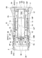
軸中心に沿って軸孔10Hが貫通形成されたノズル軸10と、ノズル軸10先端に拡径固定された第一ノズルコマ11と、ノズル軸10先端近傍に拡径固定された第二ノズルコマ12と、第二ノズルコマ12より軸方向後方にてノズル軸10の周部外方に張り出す基体保持アーム13と、基体保持アーム13の外端が筒内面に固定されることでノズル軸10を筒内空間を介して内挿保持する基部枠14とを具備してなるノズル基体1と、
筒状先端を噴出口20としてノズル基体1の前部側に軸方向移動可能に外嵌された外枠21と、外枠21の枠内から軸中心側へ張り出し形成された閉塞前板22とを具備してなり、
外枠21のノズル基体1に対する軸方向位置によって、閉塞前板22と第一ノズルコマ11、閉塞前板22と第二ノズルコマ12の各組を選択して接触状態とし、又は前記各組共に非接触状態とし得る前枠体2と、
筒状基端を接続口30としてノズル基体1の後部側に軸方向移動可能に内嵌された内枠31と、
内枠31の枠内から軸中心方向へ張り出す枠体保持アーム32と、
前記枠体保持アーム32によって内枠31の軸方向前部に中央固定された閉塞後板33とを具備してなり、
内枠20のノズル基体1に対する軸方向位置によって、閉塞後板33とノズル軸10の軸孔後端10Eとを接触または非接触状態とし得る後枠体3と、から構成される流体ノズルであって、
ノズル基体1と前枠体2の軸方向位置関係に応じて、閉塞前板22と第一ノズルコマ11、閉塞前板22と第二ノズルコマ12の各組の接触状態/非接触状態を切り替えることで、噴出口20周縁からの流体噴出を調節し得るものであり、かつ、
ノズル基体1と後枠体3の軸方向位置関係に応じて、閉塞後板33と軸孔後端10Eの接触状態/非接触状態を切り替えることで、ノズル軸20の軸孔10Hからの流体噴出を調節し得ることを特徴とする。
(2)前記切り替え式流体ノズルにおいて、軸孔10H内に、複数の矢羽根片15Pを有した整流体15が収容されてなることが好ましい。
(3)前記いずれか記載の切り替え式流体ノズルにおいて、後ろコマ33の前面中央に、軸中心にて前方突起を有する中央突板34が設けられてなることが好ましい。
(4)前記いずれか記載の切り替え式流体ノズルにおいて、第一ノズルコマ11、第二ノズルコマ12のいずれかがノズル軸から取り外し可能に固定されることが好ましい。
In order to achieve the above object, the present invention takes the following means (1) to (4).
(1) The switchable fluid nozzle of the present invention is
A
An
Depending on the axial position of the
An
A
A
The fluid nozzle includes a
By switching the contact state / non-contact state of each set of the
Fluid ejection from the
(2) In the switchable fluid nozzle, it is preferable that a
(3) In any one of the switchable fluid nozzles described above, it is preferable that a
(4) In any one of the switchable fluid nozzles described above, it is preferable that one of the
上記構成によれば、ホース又は流体ノズルに介設可能な継ぎ手本体によって、継ぎ手の筒軸方向先側へホース先側又は流体ノズルによる流体噴出を可能としながら、噴口ヘッドから対軸方向斜め側方へ、流体を側方噴出することができる。既存のホースや流体ノズルに後付けで組み込むことで、より多種な噴出きるため、また噴出調整機構によって、ななめ側方への所定量を調節しながら噴出することができる。また継ぎ手の先側をプラグによって閉塞するかまたは閉塞可能なノズルを接続することで、軸方向先側へ流体を送らずに噴口ヘッドからのみ散水することも可能である。例えば、芝生のメンテナンス作業をはじめとする園芸や植物栽培において、必要最小限の水または薬剤を噴口ヘッドから霧状にして散布することができる。 According to the above configuration, the joint main body that can be interposed in the hose or the fluid nozzle allows the fluid to be ejected from the hose tip side or the fluid nozzle toward the cylinder axial direction side of the joint, while being diagonally opposite to the axial direction from the nozzle head. The fluid can be ejected laterally. By retrofitting into an existing hose or fluid nozzle, more types of jetting can be performed, and jetting can be performed while adjusting a predetermined amount toward the side of the lick by the jetting adjustment mechanism. Moreover, it is possible to spray water only from the nozzle head without sending the fluid to the axial front side by connecting the nozzle which can close the front side of the joint with a plug or can be closed. For example, in horticulture and plant cultivation including lawn maintenance work, the minimum amount of water or chemicals can be sprayed from the nozzle head in the form of a mist.
本発明の切り替え式流体ノズルは上記手段を講じており、拡散方向及び軸方向の2経路の流体流路を内部形成し、各流体流路に対応した2重の切り替えハンドルの調節によって、ノズル口を交換することなく簡易に様々な消化状況に応じた放水態様へ切り替えることができ、また、遠方への局所的な高圧放水を行うことができると共に、上記霧状放水と集中放水の同時消火を行うという要求に応えることができる切り替え式流体ノズルを提供するものとなった。さらに、瞬時に放水圧の切り替えが必要となるような状況に対応することが容易な切り替え構造を具備する切り替え式流体ノズルを提供するものとなった。 The switchable fluid nozzle of the present invention employs the above-described means, and internally forms two fluid flow paths in the diffusion direction and the axial direction, and adjusts the double switch handle corresponding to each fluid flow path to adjust the nozzle opening. It is possible to easily switch to a water discharge mode according to various digestion situations without exchanging water, and to perform local high-pressure water discharge to a distant place, and simultaneously extinguish the above-mentioned mist water discharge and concentrated water discharge. It became possible to provide a switchable fluid nozzle capable of meeting the demand to do so. Furthermore, the present invention provides a switchable fluid nozzle having a switching structure that can easily cope with a situation where the water discharge pressure needs to be switched instantaneously.
以下本発明を実施するための形態例を、実施例として示す各図と共に説明する。図1〜図3bは実施例1の切り替え式流体ノズルであって、図4a〜図5bは実施例2の切り替え式流体ノズルであって、図6は実施例2に使用する整流体である。 DESCRIPTION OF THE PREFERRED EMBODIMENTS Embodiments for carrying out the present invention will be described below with reference to the drawings shown as examples. FIGS. 1 to 3b are switching type fluid nozzles of the first embodiment, FIGS. 4a to 5b are switching type fluid nozzles of the second embodiment, and FIG. 6 is a rectifier used in the second embodiment.
〔基本構成〕 実施例の切り替え式流体ノズルは、基本的に、
軸中心に沿って軸孔10Hが貫通形成されたノズル軸10と、ノズル軸10先端に拡径固定された第一ノズルコマ11と、ノズル軸10先端近傍に拡径固定された第二ノズルコマ12と、第二ノズルコマ12より軸方向後方にてノズル軸10の周部外方に張り出す基体保持アーム13と、基体保持アーム13の外端が筒内面に固定されることでノズル軸10を筒内空間を介して内挿保持する基部枠14とを具備してなるノズル基体1と、
筒状先端を噴出口20としてノズル基体1の前部側に軸方向移動可能に外嵌された外枠21と、外枠21の枠内から軸中心側へ張り出し形成された閉塞前板22とを具備してなり、
外枠21のノズル基体1に対する軸方向位置によって、閉塞前板22と第一ノズルコマ11、閉塞前板22と第二ノズルコマ12の各組を選択して接触状態とし、又は前記各組共に非接触状態とし得る前枠体2と、
筒状基端を接続口30としてノズル基体1の後部側に軸方向移動可能に内嵌された内枠31と、
内枠31の枠内から軸中心方向へ張り出す枠体保持アーム32と、
前記保持アームによって内枠31の軸方向前部に中央固定された閉塞後板33とを具備してなり、
内枠20のノズル基体1に対する軸方向位置によって、閉塞後板33とノズル軸10の軸孔後端10Eとを接触または非接触状態とし得る後枠体3と、から構成される流体ノズルであって、
ノズル基体1と前枠体2の軸方向位置関係に応じて、閉塞前板22と第一ノズルコマ11、閉塞前板22と第二ノズルコマ12の各組の接触状態/非接触状態を切り替えることで、噴出口20周縁からの流体噴出を調節し得るものであり、かつ、ノズル基体1と後枠体3の軸方向位置関係に応じて、閉塞後板33と軸孔後端10Eの接触状態/非接触状態を切り替えることで、ノズル軸20の軸孔10Hからの流体噴出を調節し得ることを特徴とする。
[Basic configuration] The switchable fluid nozzle of the example is basically
A
An
Depending on the axial position of the
An
A
A closed
The fluid nozzle includes a
By switching the contact state / non-contact state of each set of the
(整流体15)軸孔10H内に、複数の矢羽根片15Pを有した整流体15が収容されてなることが好ましい。実施例の整流体15は、軸直交断面にて十字に組んだ四枚羽の2つの組み板からなる。各組み板は軸方向一端側に突出した片傾斜辺を有する台形状の矢羽根片151からなり、他端側は外角部に方形切り欠きを有する軸直交辺を端部とする方形部152からなる。2つの整流体15がそれぞれの矢羽根片151の先端突部153を軸方向相反させて軸直交辺同士が当接するように組み合せられる。十字羽根状の整流板を2枚、同軸上に組み合わせることで、断面視8枚分の整流効果を期待することができる。
(中央突板34)後ろコマ33の前面中央に、軸中心にて前方突起を有する中央突板34が設けられてなる。
(第一ノズルコマ、第二ノズルコマ)第一ノズルコマ、第二ノズルコマのいずれかがノズル軸から取り外し可能に固定されることが好ましい。
(Rectifier 15) It is preferable that a
(Center protrusion 34) A
(First Nozurukoma, second Nozurukoma) first Nozurukoma, that either the second Nozurukoma is removably secured from the nozzle axis preferred.
(使用方法)
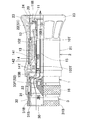
第一、第二、第三状態は中央流路の閉塞によって軸内から棒状の高圧流体の噴出を行うものである。このうち第一状態及び第三状態は、軸周部の第一流路が閉塞された状態であり、第二状態は、軸周部の第一流路が最解放された状態である。具体的には後ろ枠体3を前枠体2に対して前方に螺子移動させ、閉塞後ろコマをノズル軸の軸後ろ端に対して圧着させた、軸内の第二流路閉塞状態とする。そのうえで第一状態は、ノズル基体1を前枠体2に対して最後方に螺子移動させ、ノズル軸の後部の第二ノズルコマ12を前枠体の閉塞前板22の後面に圧着させて、軸周部の第一流路を閉塞させた状態である。また第三状態は、
ノズル基体1を前枠体2に対して最前方に螺子移動させ、ノズル軸の前部の第一ノズルコマ11を前枠体の閉塞前板22の前面に圧着させて、軸周部の第一流路を閉塞させた状態であ
る。第一状態と第三状態は、共に閉塞状態ではあるが、前端に位置するか後端に位置するかで状態が異なり、その後の軸体の移動可能方向が異なる。
(how to use)
In the first, second, and third states, a rod-shaped high-pressure fluid is ejected from the shaft by closing the central flow path. Among these, the first state and the third state are states where the first flow path of the shaft peripheral portion is closed, and the second state is a state where the first flow passage of the shaft peripheral portion is most released. Specifically, the
The
第二状態は、ノズル軸体が第一状態と第二状態の中間の位置にあるものであり、第一流路は最大開放状態となる。 In the second state, the nozzle shaft is in a position intermediate between the first state and the second state, and the first flow path is in the maximum open state.
第四、第五、第六状態は中央流路の解放によって軸内から棒状の高圧流体の噴出を行うものである。このうち第四状態及び第六状態は、軸周部の第一流路が閉塞された状態であり、第二状態は、軸周部の第一流路が最解放された状態である。(うち第五状態のみ図面省略)。具体的には後ろ枠体3を前枠体2に対して後方に螺子移動させ、閉塞後ろコマをノズル軸の軸後ろ端に対して離間させた、軸内の第二流路開放状態とする。
In the fourth, fifth, and sixth states, the bar-shaped high-pressure fluid is ejected from the shaft by releasing the central flow path. Among these, the fourth state and the sixth state are states where the first flow path of the shaft peripheral portion is closed, and the second state is a state where the first flow passage of the shaft peripheral portion is most released. (Of which only the fifth state is omitted). Specifically, the
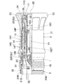
実施例2の切り替え式流体ノズルは、基本的な動作及び構成において実施例1と共通するものの、ノズル軸のコマ構成、後ろ枠体2のうち閉塞後ろコマの構成、及び整流板の構成が異なる。
Although the switchable fluid nozzle of the second embodiment is common in the basic operation and configuration to the first embodiment, the configuration of the nozzle shaft, the configuration of the closed rear frame of the
実施例2の整流体15は図6に示すように円筒板154の内面に軸方向に沿って方形の多数の突出片155が配列される。軸中央の流量を確保したうえで断面視8枚分の整流効果を期待することができる。
As shown in FIG. 6, in the rectifying
その他本発明は上述の実施例に限定されることなく、本発明の趣旨を逸脱しない範囲で種々の配置変更、一体−別体化の構成変更、ヘッド数及びヘッド角度の配置、向きの変更、及び噴出口ヘッドの噴出口及び内部流通構造の変更、並びに、流体流路の形成方向又は形成本数や遮断板の配置並びに調節方法等を変更することができる。 Others The present invention is not limited to the above-described embodiments, but various arrangement changes, integral-separated configuration changes, arrangements of the number of heads and head angles, and orientation changes without departing from the spirit of the invention. In addition, it is possible to change the jet outlet and the internal flow structure of the jet head, the formation direction or number of the fluid flow paths, the arrangement of the blocking plates, the adjustment method, and the like.
ノズル基体1
軸孔10H
軸後端10B
軸前端10F
ノズル軸10
第一ノズルコマ11
第二ノズルコマ12
基体保持アーム13
筒内空間1H
基部枠14
整流体15
矢羽根片151
方形部152
先端突部153
基部ハンドル16
前枠体2
噴出口20
外枠21
閉塞前板22
拡径端23
整流リブ24
筒内板25
S1第一接触状態
S2第二接触状態
S3非接触状態
後枠体3
接続口30
内枠31
枠後部31B
内ネジ31S
枠体保持アーム32
閉塞後コマ33
閉塞板33F
中央突部34
軸孔後端10E
Shaft
In-
Base handle 16
In-
S1 first contact state S2 second contact state S3 non-contact state
Frame
Post-blocking top 33
Blocking
Shaft hole rear end 10E
Claims (4)
外枠のノズル基体に対する軸方向位置によって、閉塞前板と第一ノズルコマ、閉塞前板と第二ノズルコマの各組を選択して接触状態とし、又は前記各組共に非接触状態とし得る前枠体と、筒状基端を接続口としてノズル基体の後部側に軸方向移動可能に内嵌された内枠と、内枠の枠内から軸中心方向へ張り出す枠体保持アームと、前記枠体保持アームによって内枠の軸方向前部に中央固定された後ろコマとを具備してなり、
内枠のノズル基体に対する軸方向位置によって、後ろコマとノズル軸の軸孔後端とを接触または非接触状態とし得る後枠体と、から構成される流体ノズルであって、
ノズル基体と前枠体の軸方向位置関係に応じて、閉塞前板と第一ノズルコマ、閉塞前板と第二ノズルコマの各組の接触状態/非接触状態を切り替えることで、噴出口周縁からの流体噴出を調節し得るものであり、かつ、ノズル基体と後枠体の軸方向位置関係に応じて、後ろコマと軸孔後端の接触状態/非接触状態を切り替えることで、ノズル軸の軸孔からの流体噴出を調節し得ることを特徴とする切り替え式流体ノズル。 A nozzle shaft in which a shaft hole is formed through the shaft center, a first nozzle piece having an enlarged diameter fixed at the tip of the nozzle shaft, a second nozzle piece having an enlarged diameter fixed in the vicinity of the nozzle shaft tip, and a shaft from the second nozzle piece Nozzle comprising a base holding arm that protrudes outward from the periphery of the nozzle shaft in the rear direction, and a base frame that inserts and holds the nozzle shaft by fixing the outer end of the base holding arm to the inner surface of the cylinder A base body, an outer frame externally fitted to the front side of the nozzle base body with a cylindrical tip as a jet outlet, and a closed front plate formed to project from the frame of the outer frame to the axial center side And
Depending on the axial position of the outer frame with respect to the nozzle base, the front frame and the first nozzle piece, the front block and the second nozzle piece can be selected to be in contact with each other, or the front frame can be in non-contact with each set. An inner frame that is fitted into the rear side of the nozzle base so as to be axially movable with the cylindrical base end as a connection port, a frame holding arm that protrudes from the inside of the inner frame toward the axial center, and the frame A rear frame fixed at the center in the axial front of the inner frame by a holding arm ;
A fluid nozzle composed of a rear frame body capable of bringing the rear frame and the rear end of the shaft hole of the nozzle shaft into contact or non-contact depending on the axial position of the inner frame with respect to the nozzle base,
By switching the contact state / non-contact state of each set of the front plate and the first nozzle piece, the front plate and the second nozzle piece according to the axial positional relationship between the nozzle base body and the front frame body, The nozzle of the nozzle shaft can be adjusted by switching the contact state / non-contact state between the rear frame and the rear end of the shaft hole according to the axial positional relationship between the nozzle base body and the rear frame body. A switchable fluid nozzle characterized in that fluid ejection from a hole can be adjusted.
Priority Applications (1)
| Application Number | Priority Date | Filing Date | Title |
|---|---|---|---|
| JP2011239834A JP6285621B2 (en) | 2011-10-31 | 2011-10-31 | Switchable fluid nozzle |
Applications Claiming Priority (1)
| Application Number | Priority Date | Filing Date | Title |
|---|---|---|---|
| JP2011239834A JP6285621B2 (en) | 2011-10-31 | 2011-10-31 | Switchable fluid nozzle |
Publications (2)
| Publication Number | Publication Date |
|---|---|
| JP2013094426A JP2013094426A (en) | 2013-05-20 |
| JP6285621B2 true JP6285621B2 (en) | 2018-02-28 |
Family
ID=48617015
Family Applications (1)
| Application Number | Title | Priority Date | Filing Date |
|---|---|---|---|
| JP2011239834A Active JP6285621B2 (en) | 2011-10-31 | 2011-10-31 | Switchable fluid nozzle |
Country Status (1)
| Country | Link |
|---|---|
| JP (1) | JP6285621B2 (en) |
Families Citing this family (2)
| Publication number | Priority date | Publication date | Assignee | Title |
|---|---|---|---|---|
| JP6328444B2 (en) * | 2014-02-25 | 2018-05-23 | 株式会社船舶配管機器テクノロジー | Nozzle for fire fighting |
| JP7019180B2 (en) * | 2018-04-16 | 2022-02-15 | ヨネ株式会社 | Water discharge nozzle that can change the injection form |
Family Cites Families (3)
| Publication number | Priority date | Publication date | Assignee | Title |
|---|---|---|---|---|
| JPS6329554U (en) * | 1986-08-12 | 1988-02-26 | ||
| JP2984852B2 (en) * | 1990-10-18 | 1999-11-29 | 能美防災株式会社 | Automatic variable nozzle |
| CA2092495C (en) * | 1992-03-26 | 1998-07-28 | Mitsuaki Oshima | Communication system |
-
2011
- 2011-10-31 JP JP2011239834A patent/JP6285621B2/en active Active
Also Published As
| Publication number | Publication date |
|---|---|
| JP2013094426A (en) | 2013-05-20 |
Similar Documents
| Publication | Publication Date | Title |
|---|---|---|
| EP2496360B1 (en) | Outlet for a washing installation | |
| JP6180528B2 (en) | Modular dual vector fluid spray nozzle | |
| JP6285621B2 (en) | Switchable fluid nozzle | |
| JP2011167822A (en) | Injection nozzle for dry ice snow washing device | |
| WO2015061144A1 (en) | Spray gun | |
| CN203899782U (en) | Water mist spray head with automatic switching function | |
| CN209108502U (en) | Fine mist spray head | |
| US20200222736A1 (en) | Fog-cloud generating nozzle | |
| JP6328444B2 (en) | Nozzle for fire fighting | |
| JP4361590B1 (en) | Fire extinguishing nozzle device | |
| CN102909139B (en) | Injection apparatus and spray gun | |
| EP0738174B1 (en) | Nozzle for spreading water fog | |
| KR100938935B1 (en) | Fire-fighting apparatus | |
| TW200613033A (en) | High pressure nozzle for spraying water mist | |
| CN108348797A (en) | Fire nozzle | |
| CN209885087U (en) | Fire water monitor | |
| JP4060999B2 (en) | Fire spray nozzle | |
| JP2013094427A (en) | Fire fighting nozzle | |
| KR20230064743A (en) | Pistol fireman window that can connect multiple fire hoses | |
| CN203043386U (en) | Multifunctional fire branch | |
| CN201939919U (en) | Water-mist spray gun for fire fighting | |
| CN211659127U (en) | Mix little spraying fire-fighting lance rifle head | |
| CN217472631U (en) | Fire-extinguishing water gun | |
| JP6267061B2 (en) | Spray gun | |
| CN101507867A (en) | Injection gun for fire fighting |
Legal Events
| Date | Code | Title | Description |
|---|---|---|---|
| A621 | Written request for application examination |
Free format text: JAPANESE INTERMEDIATE CODE: A621 Effective date: 20141031 |
|
| RD04 | Notification of resignation of power of attorney |
Free format text: JAPANESE INTERMEDIATE CODE: A7424 Effective date: 20141105 |
|
| A131 | Notification of reasons for refusal |
Free format text: JAPANESE INTERMEDIATE CODE: A131 Effective date: 20160210 |
|
| A02 | Decision of refusal |
Free format text: JAPANESE INTERMEDIATE CODE: A02 Effective date: 20160928 |
|
| A521 | Written amendment |
Free format text: JAPANESE INTERMEDIATE CODE: A523 Effective date: 20170130 |
|
| A911 | Transfer to examiner for re-examination before appeal (zenchi) |
Free format text: JAPANESE INTERMEDIATE CODE: A911 Effective date: 20170213 |
|
| A912 | Re-examination (zenchi) completed and case transferred to appeal board |
Free format text: JAPANESE INTERMEDIATE CODE: A912 Effective date: 20170224 |
|
| R155 | Notification before disposition of declining of application |
Free format text: JAPANESE INTERMEDIATE CODE: R155 |
|
| A61 | First payment of annual fees (during grant procedure) |
Free format text: JAPANESE INTERMEDIATE CODE: A61 Effective date: 20180202 |
|
| R150 | Certificate of patent or registration of utility model |
Ref document number: 6285621 Country of ref document: JP Free format text: JAPANESE INTERMEDIATE CODE: R150 |
|
| R250 | Receipt of annual fees |
Free format text: JAPANESE INTERMEDIATE CODE: R250 |
|
| R250 | Receipt of annual fees |
Free format text: JAPANESE INTERMEDIATE CODE: R250 |