JP6284445B2 - Quick coupler - Google Patents
Quick coupler Download PDFInfo
- Publication number
- JP6284445B2 JP6284445B2 JP2014131346A JP2014131346A JP6284445B2 JP 6284445 B2 JP6284445 B2 JP 6284445B2 JP 2014131346 A JP2014131346 A JP 2014131346A JP 2014131346 A JP2014131346 A JP 2014131346A JP 6284445 B2 JP6284445 B2 JP 6284445B2
- Authority
- JP
- Japan
- Prior art keywords
- lock
- hydraulic cylinder
- hook
- connecting pin
- pin
- Prior art date
- Legal status (The legal status is an assumption and is not a legal conclusion. Google has not performed a legal analysis and makes no representation as to the accuracy of the status listed.)
- Expired - Fee Related
Links
Images


Classifications
-
- E—FIXED CONSTRUCTIONS
- E02—HYDRAULIC ENGINEERING; FOUNDATIONS; SOIL SHIFTING
- E02F—DREDGING; SOIL-SHIFTING
- E02F3/00—Dredgers; Soil-shifting machines
- E02F3/04—Dredgers; Soil-shifting machines mechanically-driven
- E02F3/28—Dredgers; Soil-shifting machines mechanically-driven with digging tools mounted on a dipper- or bucket-arm, i.e. there is either one arm or a pair of arms, e.g. dippers, buckets
- E02F3/36—Component parts
- E02F3/3604—Devices to connect tools to arms, booms or the like
- E02F3/3609—Devices to connect tools to arms, booms or the like of the quick acting type, e.g. controlled from the operator seat
- E02F3/3663—Devices to connect tools to arms, booms or the like of the quick acting type, e.g. controlled from the operator seat hydraulically-operated
-
- E—FIXED CONSTRUCTIONS
- E02—HYDRAULIC ENGINEERING; FOUNDATIONS; SOIL SHIFTING
- E02F—DREDGING; SOIL-SHIFTING
- E02F3/00—Dredgers; Soil-shifting machines
- E02F3/04—Dredgers; Soil-shifting machines mechanically-driven
- E02F3/28—Dredgers; Soil-shifting machines mechanically-driven with digging tools mounted on a dipper- or bucket-arm, i.e. there is either one arm or a pair of arms, e.g. dippers, buckets
- E02F3/36—Component parts
- E02F3/3604—Devices to connect tools to arms, booms or the like
- E02F3/3609—Devices to connect tools to arms, booms or the like of the quick acting type, e.g. controlled from the operator seat
- E02F3/3618—Devices to connect tools to arms, booms or the like of the quick acting type, e.g. controlled from the operator seat with two separating hooks
-
- E—FIXED CONSTRUCTIONS
- E02—HYDRAULIC ENGINEERING; FOUNDATIONS; SOIL SHIFTING
- E02F—DREDGING; SOIL-SHIFTING
- E02F3/00—Dredgers; Soil-shifting machines
- E02F3/04—Dredgers; Soil-shifting machines mechanically-driven
- E02F3/28—Dredgers; Soil-shifting machines mechanically-driven with digging tools mounted on a dipper- or bucket-arm, i.e. there is either one arm or a pair of arms, e.g. dippers, buckets
- E02F3/36—Component parts
- E02F3/3604—Devices to connect tools to arms, booms or the like
- E02F3/3609—Devices to connect tools to arms, booms or the like of the quick acting type, e.g. controlled from the operator seat
- E02F3/3645—Devices to connect tools to arms, booms or the like of the quick acting type, e.g. controlled from the operator seat with auto-engagement means for automatic snap-on of the tool coupler part
Description
本発明は、クイックカプラに関する。 The present invention relates to a quick coupler.
油圧ショベルなどの作業車両には、バケット、カッター、ブレーカ、フォークなどの多様なアタッチメントが取り付けられる。このようなアタッチメントを作業車両に簡易に取り付けるための部品として、クイックカプラが知られている。クイックカプラは、作業車両に取り付けられる。 Various attachments such as buckets, cutters, breakers, and forks are attached to work vehicles such as hydraulic excavators. A quick coupler is known as a component for easily attaching such an attachment to a work vehicle. The quick coupler is attached to the work vehicle.
例えば、特許文献1に示すように、クイックカプラは、固定フックと可動フックとを有しており、これらのフックがアタッチメントに設けられた2つのピンに係止することで、アタッチメントがクイックカプラに連結される。
For example, as shown in
上記のようにフックによってアタッチメントがクイックカプラに取り付けられる場合、フックに対してピンを抜け止めするためのロック部材が設けられることが好ましい。例えば、特許文献1のクイックカプラでは、可動フックに設けられたボスにロックピンが挿入されることで、フックに対するピンの抜け止めがなされる。
When the attachment is attached to the quick coupler by the hook as described above, it is preferable to provide a lock member for preventing the pin from coming off from the hook. For example, in the quick coupler of
しかし、特許文献1のクイックカプラでは、作業者によってロックピンが装着される。そのような作業は煩雑であるため、アタッチメントの装着時に自動的にロック部材による抜け止め機能が作用することが好ましい。また、アタッチメントの取り外し時には、自動的にロック部材による抜け止め機能が解除されることが好ましい。
However, in the quick coupler of
本発明の課題は、アタッチメントの着脱時に自動的にロック部材による抜け止め機能の作用と解除とが行われるクイックカプラを提供することにある。 An object of the present invention is to provide a quick coupler in which the action of releasing and preventing the lock member is automatically performed and released when the attachment is attached or detached.
本発明の一態様に係るクイックカプラは、カプラ本体と、可動部材と、油圧シリンダと、第2連結ピンと、第2ロック部材と、付勢部材と、を備える。カプラ本体は、第1のフックを有する。可動部材は、第2のフックを有し、カプラ本体に対して可動的に支持される。油圧シリンダは、カプラ本体に接続される第1端部と、可動部材に接続される第2端部とを有する。油圧シリンダは、伸張することによって第2のフックが第1のフックから離れるように可動部材を移動させる。油圧シリンダは、収縮することによって第2のフックが第1のフックに近づくように可動部材を移動させる。 A quick coupler according to an aspect of the present invention includes a coupler main body, a movable member, a hydraulic cylinder, a second connecting pin, a second lock member, and an urging member. The coupler body has a first hook. The movable member has a second hook and is movably supported with respect to the coupler main body. The hydraulic cylinder has a first end connected to the coupler main body and a second end connected to the movable member. The hydraulic cylinder moves to move the movable member so that the second hook is separated from the first hook. The hydraulic cylinder moves the movable member so that the second hook approaches the first hook by contracting.
第2連結ピンは、油圧シリンダの第2端部と可動部材とを連結する。第2ロック部材は、ロックオン位置と、ロックオフ位置とに移動可能に設けられる。第2ロック部材は、ロックオン位置において第2のフックの開口内に突出する。第2ロック部材は、ロックオン位置において、ロックオン位置から退いた状態となる。付勢部材は、第2ロック部材をロックオン位置に向かって付勢する。 The second connecting pin connects the second end of the hydraulic cylinder and the movable member. The second lock member is provided to be movable between a lock-on position and a lock-off position. The second lock member projects into the opening of the second hook at the lock-on position. The second lock member is in a state of being retracted from the lock-on position at the lock-on position. The biasing member biases the second lock member toward the lock-on position.
可動部材は、第2支持孔を有する。第2支持孔は、油圧シリンダの伸縮方向に沿ったロック解除位置とロック作動位置との間で第2連結ピンを可動的に支持する。油圧シリンダが伸長することで、第2連結ピンは、ロック解除位置からロック作動位置へ移動する。油圧シリンダが収縮することで、第2連結ピンは、ロック作動位置からロック解除位置へ移動する。第2ロック部材は、第2支持孔と重なるように配置されるガイド孔を有する。第2連結ピンは、第2支持孔とガイド孔とに挿入されている。 The movable member has a second support hole. The second support hole movably supports the second connecting pin between the lock release position and the lock operation position along the expansion / contraction direction of the hydraulic cylinder. As the hydraulic cylinder extends, the second connecting pin moves from the unlocked position to the locked operating position. When the hydraulic cylinder contracts, the second connecting pin moves from the lock operation position to the lock release position. The second lock member has a guide hole disposed so as to overlap the second support hole. The second connecting pin is inserted into the second support hole and the guide hole.
ガイド孔の縁は、第1接触部と、第2接触部と、ガイド部と、を有する。第1接触部は、第2連結ピンがロック作動位置に位置している状態で第2連結ピンと接触する。第2接触部は、第2連結ピンがロック解除位置に位置している状態で第2連結ピンと接触する。ガイド部は、第1接触部と第2接触部との間において第2連結ピンの移動方向に対して交差する方向に延びている。ガイド部は、ロック作動位置からロック解除位置に移動する第2連結ピンによって押圧されることで、付勢部材の付勢力に抗して、第2ロック部材をロックオン位置からロックオフ位置に移動させる。 The edge of the guide hole has a first contact portion, a second contact portion, and a guide portion. The first contact portion contacts the second connection pin in a state where the second connection pin is located at the lock operation position. The second contact portion contacts the second connection pin in a state where the second connection pin is located at the unlock position. The guide portion extends between the first contact portion and the second contact portion in a direction that intersects the moving direction of the second connecting pin. The guide portion is pressed by the second connecting pin that moves from the lock operation position to the lock release position, thereby moving the second lock member from the lock-on position to the lock-off position against the urging force of the urging member. Let
本態様に係るクイックカプラでは、油圧シリンダが伸長することにより、油圧シリンダの第2端部が、第1端部から離れるように移動する。これにより、第2のフックが第1のフックから離れるように移動する。その結果、第1のフックと第2のフックとのそれぞれがアタッチメントのピンに係止して、アタッチメントがクイックカプラに取り付けられる。 In the quick coupler according to this aspect, the second end of the hydraulic cylinder moves away from the first end when the hydraulic cylinder extends. As a result, the second hook moves away from the first hook. As a result, each of the first hook and the second hook is locked to the pin of the attachment, and the attachment is attached to the quick coupler.
また、油圧シリンダが伸長すると、第2連結ピンは、ロック解除位置からロック作動位置へ移動する。このとき、付勢部材の付勢力によって第2ロック部材がロックオフ位置からロックオン位置へ移動する。これにより、自動的に第2ロック部材による抜け止め機能が作用する。 When the hydraulic cylinder is extended, the second connecting pin moves from the unlock position to the lock operation position. At this time, the second lock member moves from the lock-off position to the lock-on position by the biasing force of the biasing member. Thereby, the retaining function by the second lock member automatically acts.
逆に、油圧シリンダが収縮することにより、油圧シリンダの第2端部が、第1端部に近づくように移動する。これにより、第2のフックが第1のフックに近づくように移動する。その結果、第1のフックと第2のフックとのそれぞれがアタッチメントのピンから外れて、アタッチメントがクイックカプラから取り外される。 Conversely, when the hydraulic cylinder contracts, the second end of the hydraulic cylinder moves so as to approach the first end. Thereby, the second hook moves so as to approach the first hook. As a result, each of the first hook and the second hook is detached from the pin of the attachment, and the attachment is detached from the quick coupler.
また、油圧シリンダが収縮すると、第2連結ピンが、ロック作動位置からロック解除位置へ移動する。このとき、第2ロック部材のガイド部が、第2連結ピンによって押圧されることで、第2ロック部材が、付勢部材の付勢力に抗して、ロックオン位置からロックオフ位置に移動する。これにより、第2ロック部材による抜け止め機能が自動的に解除される。 When the hydraulic cylinder contracts, the second connecting pin moves from the lock operation position to the lock release position. At this time, the guide portion of the second lock member is pressed by the second connecting pin, so that the second lock member moves from the lock-on position to the lock-off position against the urging force of the urging member. . Thereby, the retaining function by the second lock member is automatically released.
好ましくは、第2支持孔は、油圧シリンダの伸縮方向に沿って延びる長孔である。この場合、第2端部は、長孔に沿って油圧シリンダの伸縮方向に移動することで、第2ロック部材による抜け止め機能を作用させることができる。このため、クイックカプラの構造を簡素化することができる。 Preferably, the second support hole is a long hole extending along the expansion / contraction direction of the hydraulic cylinder. In this case, the second end portion can move in the expansion / contraction direction of the hydraulic cylinder along the elongated hole, thereby allowing the second locking member to function as a retaining member. For this reason, the structure of the quick coupler can be simplified.
好ましくは、第2ロック部材は、ロックオン位置とロックオフ位置との間で回動可能に可動部材に支持される。この場合、簡易な構造で第2ロック部材を支持することができる。 Preferably, the second lock member is supported by the movable member so as to be rotatable between a lock-on position and a lock-off position. In this case, the second lock member can be supported with a simple structure.
好ましくは、ガイド孔の縁は、第1隅部と、第2隅部と、第3隅部と、第1接続部と、第2接続部と、第3接続部と、を有する。第1隅部は、第1接触部を含む。第2隅部は、第2接触部を含む。第3隅部は、第1隅部に対して第2ロック部材の移動方向に配置される。第1接続部は、ガイド部を含み、第1隅部と第2隅部とを接続する。第2接続部は、第2隅部と第3隅部とを接続する。第3接続部は、第3隅部と第1隅部とを接続する。この場合、簡易な構造で第2ロック部材を第2連結ピンの動作に連動させることができる。 Preferably, the edge of the guide hole includes a first corner portion, a second corner portion, a third corner portion, a first connection portion, a second connection portion, and a third connection portion. The first corner includes a first contact portion. The second corner includes a second contact portion. The third corner is disposed in the moving direction of the second lock member with respect to the first corner. The first connection part includes a guide part and connects the first corner part and the second corner part. The second connection portion connects the second corner portion and the third corner portion. The third connection portion connects the third corner portion and the first corner portion. In this case, the second lock member can be interlocked with the operation of the second connecting pin with a simple structure.
好ましくは、第2連結ピンがロック作動位置に位置する状態で第2ロック部材がロックオン位置からロックオフ位置に移動可能なように、ガイド孔の第3隅部は、ロック作動位置に位置する第2連結ピンに対して間隔をおいて下方に配置される。 Preferably, the third corner portion of the guide hole is positioned at the lock operation position so that the second lock member can move from the lock-on position to the lock-off position in a state where the second connecting pin is positioned at the lock operation position. It arrange | positions below at intervals with respect to a 2nd connection pin.
この場合、第2連結ピンがロック作動位置に位置していても、第2ロック部材はロックオン位置からロックオフ位置に移動可能である。従って、アタッチメントのピンを第2のフックの開口の外方から第2ロック部材に押し付けることで、第2ロック部材を付勢部材の付勢力に抗してロックオン位置からロックオフ位置に移動させることができる。これにより、第2ロック部材がロックオン位置に位置していても、アタッチメントのピンを第2のフックの開口に挿入することができる。 In this case, the second lock member can move from the lock-on position to the lock-off position even if the second connecting pin is located at the lock operation position. Accordingly, the second lock member is moved from the lock-on position to the lock-off position against the urging force of the urging member by pressing the attachment pin against the second lock member from the outside of the opening of the second hook. be able to. Thereby, even if the 2nd lock member is located in a lock on position, the pin of an attachment can be inserted in the opening of the 2nd hook.
好ましくは、クイックカプラは、第1ロック部材と、第1連結ピンと、をさらに備える。第1ロック部材は、ロックオン位置とロックオフ位置とに移動可能に設けられる。第1ロック部材は、ロックオン位置において、第1のフックの開口内に突出する。第1ロック部材は、ロックオフ位置において、ロックオン位置から退いた状態となる。第1連結ピンは、油圧シリンダの第1端部とカプラ本体とを連結する。 Preferably, the quick coupler further includes a first lock member and a first connecting pin. The first lock member is provided to be movable between a lock-on position and a lock-off position. The first lock member protrudes into the opening of the first hook at the lock-on position. The first lock member is retracted from the lock-on position at the lock-off position. The first connecting pin connects the first end of the hydraulic cylinder and the coupler body.
カプラ本体は、第1連結ピンを油圧シリンダの伸縮方向に可動的に支持する第1支持孔を有する。油圧シリンダの第1端部は、第1連結ピンの可動範囲内で第2端部から離れるように移動することで第1ロック部材をロックオフ位置からロックオン位置に移動させる。 The coupler main body has a first support hole that movably supports the first connecting pin in the expansion / contraction direction of the hydraulic cylinder. The first end of the hydraulic cylinder moves away from the second end within the movable range of the first connecting pin, thereby moving the first lock member from the lock-off position to the lock-on position.
この場合、油圧シリンダが伸長すると、油圧シリンダの第1端部が、第1連結ピンの可動範囲内で第2端部から離れるように移動する。この第1端部の動作に伴って、第1ロック部材がロックオフ位置からロックオン位置に移動する。これにより、アタッチメントの装着時に自動的に第1ロック部材による抜け止め機能を作用させることができる。 In this case, when the hydraulic cylinder extends, the first end of the hydraulic cylinder moves away from the second end within the movable range of the first connecting pin. With the operation of the first end, the first lock member moves from the lock-off position to the lock-on position. Accordingly, it is possible to automatically act as a retaining mechanism by the first lock member when the attachment is mounted.
好ましくは、第1支持孔は、油圧シリンダの伸縮方向に沿って延びる長孔である。この場合、第1端部は、長孔に沿って油圧シリンダの伸縮方向に移動することで、第1ロック部材による抜け止め機能を作用させることができる。このため、クイックカプラの構造を簡素化することができる。 Preferably, the first support hole is a long hole extending along the expansion / contraction direction of the hydraulic cylinder. In this case, the first end portion can move in the expansion / contraction direction of the hydraulic cylinder along the long hole, thereby allowing the first locking member to function as a retaining member. For this reason, the structure of the quick coupler can be simplified.
好ましくは、クイックカプラは、第1支持孔に挿入される弾性部材をさらに備える。弾性部材は、第2端部から第1端部に向かう方向に第1連結ピンを押圧する。この場合、故障により油圧シリンダの伸びる力が失われても、弾性部材の押圧力により第1連結ピンの位置が保持される。これにより、第1ロック部材がロックオン位置に保持される。 Preferably, the quick coupler further includes an elastic member inserted into the first support hole. The elastic member presses the first connecting pin in a direction from the second end toward the first end. In this case, even if the extension force of the hydraulic cylinder is lost due to failure, the position of the first connecting pin is held by the pressing force of the elastic member. As a result, the first lock member is held in the lock-on position.
好ましくは、油圧シリンダの第1端部は、第1連結ピンの可動範囲内で第2端部に近づくように移動することで、第1ロック部材をロックオン位置からロックオフ位置に移動させる。この場合、アタッチメントの取り外し時に自動的に第1ロック部材による抜け止め機能を解除することができる。 Preferably, the first end of the hydraulic cylinder moves so as to approach the second end within the movable range of the first connecting pin, thereby moving the first lock member from the lock-on position to the lock-off position. In this case, when the attachment is removed, the retaining function by the first lock member can be automatically released.
本発明によれば、アタッチメントの装着時に自動的にロック部材による抜け止め機能を作用させると共に、アタッチメントの取り外し時に自動的にロック部材による抜け止め機能を解除することができる。 According to the present invention, the retaining function by the lock member can be automatically activated when the attachment is attached, and the retaining function by the lock member can be automatically released when the attachment is detached.
以下、図面を参照して実施形態にかかるクイックカプラについて説明する。図1は、本実施形態に係るクイックカプラ1が装着された作業車両100の一部を示す側面図である。作業車両100は、例えば油圧ショベルである。ただし、作業車両100は、油圧ショベルに限らず、他の作業車両であってもよい。
Hereinafter, a quick coupler according to an embodiment will be described with reference to the drawings. FIG. 1 is a side view showing a part of a
図1に示すように、作業車両100は、アーム101とリンク部材102とアタッチメント103とを有する。なお、図1では、アタッチメント103の一例としてのバケットが図示されているが、アタッチメント103は、バケットに限らず、カッター、ブレーカ、フォークなど他のアタッチメントであってもよい。
As shown in FIG. 1, the
クイックカプラ1は、アームピン104を介してアーム101に接続される。クイックカプラ1は、リンクピン105を介してリンク部材102に接続される。クイックカプラ1は、第1のピン106と第2のピン107とを介してアタッチメント103に接続される。
The
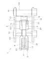
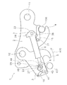
図2は、クイックカプラ1の平面図である。図3は、クイックカプラ1の内部の概略構成を示す側面断面図である。図2及び図3に示すように、クイックカプラ1は、カプラ本体2と可動部材3とを有する。カプラ本体2は、アームピン支持孔11とリンクピン支持孔12とを有する。アームピン支持孔11には、アームピン104が挿入される。リンクピン支持孔12には、リンクピン105が挿入される。
FIG. 2 is a plan view of the
カプラ本体2は、第1のフック4を有する。第1のフック4は、第1のピン106に係止する。可動部材3は、カプラ本体2と別体である。可動部材3は、第2のフック5を有する。第2のフック5は、第2のピン107に係止する。
The coupler
なお、本実施形態に係るクイックカプラ1においては、アームピン支持孔11に対してリンクピン支持孔12が位置する方向を前方と呼び、その反対を後方と呼ぶ。アームピン支持孔11及びリンクピン支持孔12に対して第1のフック4及び第2のフック5が位置する方向を下方と呼び、その反対を上方と呼ぶ。また、アームピン支持孔11の軸線及びリンクピン支持孔12の軸線が延びる方向を幅方向或いは側方と呼ぶ。ただし、これらの方向を示す用語は、上記のようにクイックカプラ1を見たときに特定されるものであって、クイックカプラ1の取付方向を限定するものではない。
In the
図2に示すように、カプラ本体2は、第1側面部13と第2側面部14と壁部15とを有する。第1側面部13と第2側面部14とは、それぞれ前後方向及び上下方向に延びる板状の形状を有する。第1側面部13と第2側面部14とは、幅方向に間隔をおいて配置されている。壁部15は、幅方向に延びており、第1側面部13と第2側面部14とに渡って配置されている。アームピン支持孔11とリンクピン支持孔12は、第1側面部14と第2側面部15とを幅方向に貫通するように設けられている。
As shown in FIG. 2, the coupler
可動部材3は、カプラ本体2に可動的に支持されている。詳細には、可動部材3は、リンクピン105を介してカプラ本体2に対して回動可能に支持される。
The
図3に示すように、第1のフック4と第2のフック5とは、互いに反対の方向に向かって開口している。詳細には、第1のフック4は、後方に向かって開口している。第2のフック5は、前方に向かって開口している。第2のフック5は、第1のフック4の前方に配置されている。
As shown in FIG. 3, the
クイックカプラ1は、油圧シリンダ6と、第1連結ピン7と、第2連結ピン8と、を有する。油圧シリンダ6は、油圧管21を介して、作業車両100の油圧システムに接続される。油圧シリンダ6は、油圧管21からの油圧によって伸縮する。
The
油圧シリンダ6は、第1端部22と第2端部23とを有する。第1端部22は、カプラ本体2に接続される。第2端部23は、可動部材3に接続される。詳細には、油圧シリンダ6は、シリンダチューブ24とピストンロッド25とを有する。第1端部22は、シリンダチューブ24に含まれる。第2端部23は、ピストンロッド25に含まれる。
The hydraulic cylinder 6 has a
第1連結ピン7は、油圧シリンダ6の第1端部22とカプラ本体2とを連結する。カプラ本体2は、第1支持孔26を有する。第1支持孔26は、第1側面部13と第2側面部14とを貫通するように設けられている。第1連結ピン7は第1端部22に取り付けられており、第1端部22は、第1連結ピン7を介してカプラ本体2に支持される。
The first connecting
第1連結ピン7は、第1支持孔26に挿入されている。第1支持孔26は、油圧シリンダ6の伸縮方向に沿って延びる長孔である。このため、第1支持孔26は、第1連結ピン7を油圧シリンダ6の伸縮方向に可動的に支持する。
The first connecting
第2連結ピン8は、油圧シリンダ6の第2端部23と可動部材3とを連結する。可動部材3は、第2支持孔27を有する。第2支持孔27は、可動部材3を幅方向に貫通するように設けられている。第2連結ピン8は、第2端部23に取り付けられており、第2端部23は、第2連結ピン8を介して可動部材3に支持される。第2支持孔27は、油圧シリンダ6の伸縮方向に沿って延びる長孔である。このため、第2支持孔27は、第2連結ピン8を油圧シリンダ6の伸縮方向に可動的に支持する。
The second connecting
図2及び図3に示すように、壁部15は、開口151を有する。開口151は、第1端部22の上方に位置する。図3に示すように、開口151を通して、油圧管21がカプラ本体2内に導入されている。
As shown in FIGS. 2 and 3, the
図4は、油圧シリンダ6が図3に示す状態から伸張した状態を示す側面断面図である。図5は、油圧シリンダ6が図4に示す状態から更に伸張した状態を示す側面断面図である。図4及び図5に示すように、油圧シリンダ6が伸長することにより、第2端部23は第1端部22から離れるように移動する。これにより、油圧シリンダ6は、第2のフック5が第1のフック4から離れるように、可動部材3をカプラ本体2に対して回動させる。
4 is a side sectional view showing a state in which the hydraulic cylinder 6 is extended from the state shown in FIG. FIG. 5 is a side sectional view showing a state where the hydraulic cylinder 6 is further extended from the state shown in FIG. As shown in FIGS. 4 and 5, when the hydraulic cylinder 6 extends, the
図6は、油圧シリンダ6が図5に示す状態から収縮した状態を示す側面断面図である。図7は、油圧シリンダ6が図6に示す状態から更に収縮した状態を示す側面断面図である。図6及び図7に示すように、油圧シリンダ6が収縮することにより、第2端部23は第1端部22に近づくように移動する。これにより、油圧シリンダ6は、第2のフック5が第1のフック4に近づくように、可動部材3をカプラ本体2に対して回動させる。
6 is a side sectional view showing a state in which the hydraulic cylinder 6 is contracted from the state shown in FIG. FIG. 7 is a side sectional view showing a state where the hydraulic cylinder 6 is further contracted from the state shown in FIG. As shown in FIGS. 6 and 7, when the hydraulic cylinder 6 contracts, the
なお、理解の容易のため、図4から図7においては、図3に示す構成の一部が省略されている。 For easy understanding, a part of the configuration shown in FIG. 3 is omitted in FIGS.
図3に示すように、クイックカプラ1は、第1ロック部材16と、第2ロック部材17と、付勢部材18と、を有する。第1ロック部材16は、アタッチメント103の装着時に第1のフック4を自動的に抜け止めする機能を有する。以下、第1ロック部材16に関する構成について説明する。
As shown in FIG. 3, the
第1ロック部材16は、第1のフック4の上方に配置される。第1ロック部材16は、第1ロック連結ピン31を介してカプラ本体2に接続されている。第1ロック部材16は、基端部32と先端部33と有する。基端部32は、カプラ本体2に対して回転可能に支持されている。先端部33は、下方に向かって屈曲したフック状の形状を有する。すなわち、先端部33は、第1のフック4に向かって屈曲したフック状の形状を有する。
The
第1ロック部材16は、第1ロックオン位置と第1ロックオフ位置とに移動可能に設けられる。図3は、第1ロック部材16が第1ロックオフ位置に位置している状態を示している。図4及び図5は、第1ロック部材16が第1ロックオン位置に位置している状態を示している。
The
図4及び図5に示すように、第1ロックオン位置において、第1ロック部材16の先端部33は第1のフック4の開口内に突出している。これにより、第1のピン106が第1のフック4から抜け止めされる。図3に示すように、第1ロックオフ位置において、第1ロック部材16の先端部33は、第1ロックオン位置から退いた状態となる。詳細には、第1ロックオフ位置において、第1ロック部材16の先端部33は、第1のフック4の開口内から退いた状態となる。
As shown in FIGS. 4 and 5, the
油圧シリンダ6の第1端部22は、第2端部23から離れるように移動することで保持位置に移動する。図5は、第1端部22が保持位置に位置している状態を示している。第1端部22は、保持位置において、第1ロック部材16を第1ロックオン位置に保持する。逆に、第1端部22は、第2端部23に近づくように移動することで、解除位置に移動する。図3は、第1端部22が解除位置に位置している状態を示している。第1端部22は、解除位置において、第1ロック部材16の保持を解除する。
The
詳細には、油圧シリンダ6の第1端部22は、第1ロック部材16に向かって突出する凸部34を有する。凸部34は、下方に向かって突出している。第1ロック部材16は、凹部35と受け部36を有する。凹部35と受け部36とは、基端部32と先端部33との間に位置する。凹部35は、第1ロック部材16の上面から下方に向かって凹んだ形状を有する。受け部36は、凹部35の後方に位置する。
Specifically, the
図5に示すように、第1端部22が保持位置に位置している状態では、凸部34は受け部36に接触しており、凸部34は、第1ロック部材16を第1のフック4に向かって押圧している。これにより、第1ロック部材16が第1ロックオン位置に保持される。図3に示すように、第1端部22が解除位置に位置している状態では、凸部34は凹部35内に位置している。これにより、第1ロック部材16が第1ロックオフ位置に保持される。
As shown in FIG. 5, in a state where the
より詳細には、第1ロック部材16は、凹部35に接続される傾斜面37と段部38とを有する。傾斜面37と段部38とは、基端部32と先端部33との間に位置する。傾斜面37は、凹部35に対して第2端部23から第1端部22に向かう方向に配置される。すなわち、傾斜面37は、凹部35の後方に配置される。段部38は、凹部35に対して第1端部22から第2端部23に向かう方向に配置される。すなわち、段部38は、凹部35の前方に配置される。
More specifically, the
図3から図5に示すように、凸部34が凹部35から傾斜面37に移動して傾斜面37を押圧することにより、第1ロック部材16が回動して第1ロックオン位置に移動する。また、図6及び図7に示すように、凸部34が凹部35から段部38に移動して段部38を押圧することにより、第1ロック部材16が回動して第1ロックオフ位置に移動する。
As shown in FIGS. 3 to 5, when the
なお、図8に示すように、第1支持孔26には、弾性部材28が挿入される。弾性部材28は、例えばゴム製である。ただし、弾性部材28は、弾性力を生じさせる材料であればよく、ゴムに限らず他の材料であってもよい。弾性部材28は、第1支持孔26に沿った細長形状を有する。
As shown in FIG. 8, an
図8は、第1端部22が保持位置に位置している状態(図5参照)での第1連結ピン7と弾性部材28とを示している。図8に示す状態において、弾性部材28は第1連結ピン7を押圧している。図9は、図6に示すように、第1端部22が保持位置から解除位置に移動している状態での第1連結ピン7と弾性部材28とを示している。図9に示すように、第1連結ピン7が移動することで、弾性部材28が第1連結ピン7によって圧縮されている。すなわち、弾性部材28は、油圧シリンダ6が収縮するときに、第1連結ピン7によって圧縮されるように配置される。
FIG. 8 shows the first connecting
次に、第2ロック部材17に関する構成について説明する。第2ロック部材17は、アタッチメント103の装着時に第2のフック5を自動的に抜け止めする機能を有する。図3に示すように、第2ロック部材17は、第2のフック5の前方に配置される。第2ロック部材17は、第2ロック連結ピンを介して可動部材3に接続されている。第2ロック部材17は、第2ロック連結ピン41を介して可動部材3に回動可能に支持されている。
Next, the structure regarding the
第2ロック部材17は、第2ロックオン位置と第2ロックオフ位置との間で回動可能に設けられている。図3及び図4は、第2ロック部材17が第2ロックオフ位置に位置している状態を示している。図5は、第2ロック部材17が第2ロックオン位置に位置している状態を示している。
The
図5に示すように、第2ロック部材17は、第2ロックオン位置において第2のフック5の開口内に突出する。図3及び図4に示すように、第2ロック部材17は、第2ロックオン位置において、第2ロックオン位置から退いた状態となる。
As shown in FIG. 5, the
付勢部材18は、第2ロック部材17を第2ロックオン位置に向かって付勢する。付勢部材18は連結ピン57を介して可動部材3に接続されている。付勢部材18は連結ピン58を介して第2ロック部材17に接続されている。付勢部材18は、バネ42と、バネカバー43と、シャフト44とを有する。バネ42は、第2ロックオン位置と第2ロックオフ位置とのいずれの位置においても、圧縮された状態となっている。バネカバー43は、バネ42を収容している。バネカバー43は、連結ピン57を介して回動可能に可動部材3に接続されている。シャフト44は、バネ42によって押圧されており、バネカバー43から突出している。シャフト44は、連結ピン58を介して回動可能に第2ロック部材17に連結されている。
The urging
上述した第2支持孔27は、油圧シリンダ6の伸縮方向に沿ったロック解除位置とロック作動位置との間で第2連結ピン8を可動的に支持する。後述するように、ロック解除位置は、第2ロック部材17による抜け止め機能を解除する位置である。ロック作動位置は、第2ロック部材17による抜け止め機能を作動させる位置である。油圧シリンダ6が伸長することで、第2連結ピン8は、ロック解除位置からロック作動位置へ移動する。油圧シリンダ6が収縮することで、第2連結ピン8は、ロック作動位置からロック解除位置へ移動する。
The
第2ロック部材17は、ガイド孔45を有する。ガイド孔45は、第2連結ピン8の軸線方向から見て、第2支持孔27と重なるように配置される。第2連結ピン8は、第2支持孔27とガイド孔45とに挿入されている。ガイド孔45は、3つの隅部を有する略三角形状を有する。
The
図10は、第2ロック部材17及びその周囲の拡大図である。図10に示すように、ガイド孔45の縁は、第1隅部46と、第2隅部47と、第3隅部48と、第1接続部51と、第2接続部52と、第3接続部53と、を有する。
FIG. 10 is an enlarged view of the
なお、図10において“8a”は、ロック作動位置での第2連結ピン8の第2ロック部材17に対する位置を示している。また、“8b”は、ロック解除位置での第2連結ピン8の第2ロック部材17に対する位置を示している。また、“8”は、ロック作動位置とロック解除位置との間の位置での第2連結ピン8の第2ロック部材17に対する位置を示している。
In FIG. 10, “8a” indicates the position of the second connecting
第1隅部46は、第1接触部54を含む。図5に示すように、第1接触部54は、第2連結ピン8がロック作動位置に位置している状態で第2連結ピン8と接触する。第2隅部47は、第2接触部55を含む。図3に示すように、第2接触部55は、第2連結ピン8がロック解除位置に位置している状態で第2連結ピン8と接触する。第3隅部48は、第1隅部46に対して第2ロック部材17の可動方向に配置される。第3隅部48は、第1隅部46の下方に位置する。第3隅部48は、第2隅部47の前方に位置する。
The
第1接続部51は、第1隅部46と第2隅部47とを接続する。第2接続部52は、第2隅部47と第3隅部48とを接続する。第3接続部53は、第3隅部48と第1隅部46とを接続する。第1接続部51は、ガイド部56を含む。
The first connecting
ガイド部56は、第1接触部54と第2接触部55との間において第2連結ピン8の移動方向(矢印A8参照)に対して交差する方向に延びている。ガイド部56は、第2連結ピン8がロック作動位置(8a)からロック解除位置(8b)に移動する際に、第2連結ピン8によって押圧される。これにより、第2ロック部材17が、付勢部材18の付勢力に抗して、第2ロックオン位置から第2ロックオフ位置に移動する。
The
第3接続部53は、ロック作動位置(8a)に位置する第2連結ピン8から下方に延びている。このため、図5に示すように、ガイド孔45の縁は、ロック作動位置に位置する第2連結ピン8に対して間隔をおいて配置される。詳細には、第3隅部48は、ロック作動位置(8a)に位置する第2連結ピン8に対して間隔をおいて下方に配置される。すなわち、ガイド孔45は、ロック作動位置に位置する第2連結ピン8の下方に、第2連結ピン8を配置可能な空間を有している。このため、第2連結ピン8がロック作動位置に位置する状態で、第2ロック部材17が第2ロックオン位置から第2ロックオフ位置に移動可能となっている。
The third connecting
次に、クイックカプラ1にアタッチメント103を取り付けるときの動作について説明する。まず、図3に示すように、第1のピン106を第1のフック4に係止させる(矢印A1参照)。また、第1のピン106を中心にクイックカプラ1或いはアタッチメント103を回動させることにより、第2のピン107を第2のフック5の前方に配置する(矢印A2参照)。そして、油圧シリンダ6を伸長させる。
Next, an operation when attaching the
油圧シリンダ6を伸長させると、図4に示すように、第1端部22が第2端部23から離れるように第1支持孔26に沿って後方へ移動する(矢印A3参照)。これにより、凸部34が、第1ロック部材16の凹部35から傾斜面37に移動し、傾斜面37を押圧することで第1ロック部材16を回動させる(矢印A4参照)。
When the hydraulic cylinder 6 is extended, the
そして、図5に示すように、第1端部22が解除位置に到達すると、凸部34が第1ロック部材16の受け部36を押圧する。これにより、第1ロック部材16が第1ロックオン位置に到達して、第1ロック部材16によって第1のピン106が第1のフック4から抜け止めされる。また、凸部34が受け部36を押圧することによって、第1ロック部材16は第1ロックオン位置に保持される。
Then, as shown in FIG. 5, when the
また、油圧シリンダ6が伸長することにより、第2端部23が第1端部22から離れるように前方へ移動する(矢印A5参照)。そして、油圧シリンダ6がさらに伸長することにより、第2のフック5が第1のフック4から離れるように、可動部材3がカプラ本体2に対して回動する(矢印A6参照)。その結果、第2のフック5が第2のピン107に係止する。
Further, when the hydraulic cylinder 6 extends, the
また、油圧シリンダ6が伸長することにより、第2連結ピン8がロック解除位置からロック作動位置に移動する(矢印A5参照)。第2連結ピン8がロック作動位置に位置する状態では、第2連結ピン8による第2ロック部材17の第2ロックオフ位置への押圧が解除される。このため、第2ロック部材17は、付勢部材18の付勢力によって第2ロックオン位置へ移動する(矢印A7参照)。その結果。第2ロック部材17によって第2のピン107が第2のフック5から抜け止めされる。
Further, the extension of the hydraulic cylinder 6 moves the second connecting
次に、クイックカプラ1からアタッチメント103を取り外すときの動作について説明する。図6に示すように、油圧シリンダ6が収縮すると、第2端部23が第1端部22に近づくように後方へ移動する。これにより、第2連結ピン8がロック作動位置からロック解除位置へ移動する(矢印A8参照)。これにより、図10に示すように、第2連結ピン8が、第2ロック部材17のガイド部56に対して摺動しながら、第2ロック部材17を第2ロックオフ位置へ向けて押圧する。その結果、第2ロック部材17が第2ロックオフ位置へ回動する(矢印A9参照)。これにより、第2ロック部材17による抜け止めが解除される。
Next, the operation when removing the
油圧シリンダ6がさらに収縮すると、第2のフック5が第1のフック4に近づくように、可動部材3がカプラ本体2に対して回動する(矢印A10参照)。これにより、第2のフック5の第2のピン107への係止が解除される。
When the hydraulic cylinder 6 further contracts, the
また、図7に示すように、油圧シリンダ6が収縮することにより、第1端部22が第2端部23に近づくように第1支持孔26に沿って前方へ移動する(矢印A11参照)。これにより、凸部34が、第1ロック部材16の受け部36から傾斜面37を通り、凹部35に移動する。そして、凸部34が、さらに後方へ移動して段部38に係止することで、第1ロック部材16を回動させる(矢印A12参照)。これにより、第1ロック部材16が第1ロックオフ位置に移動して、第1ロック部材16による第1のピン106の抜け止めが解除される。
Further, as shown in FIG. 7, when the hydraulic cylinder 6 contracts, the
その後、第1のピン106を中心にクイックカプラ1或いはアタッチメント103を回動させることにより、第2のピン107を第2のフック5の開口に対向する位置から移動させる(矢印A13参照)。そして、第1のフック4を第1のピン106から外す(矢印A14参照)。以上のようにして、クイックカプラ1からアタッチメント103が取り外される。
Thereafter, by rotating the
なお、クイックカプラ1にアタッチメント103を取り付ける場合において、第1ロック部材16の第1ロックオン位置への移動(図4の矢印A4)と第2のフック5の回動(図5の矢印A6)との順番はどちらが先になってもよい。クイックカプラ1からアタッチメント103を取り外す場合においても同様に、第1ロック部材16の第1ロックオフ位置への移動(図7の矢印A12)と第2のフック5の回動(図6の矢印A10)との順番はどちらが先になってもよい。
When attaching the
以上説明したように、本実施形態に係るクイックカプラ1では、アタッチメント103の装着時に、自動的に第1ロック部材16と第2ロック部材17とによる抜け止め機能を作用させることができる。また、アタッチメント103の取り外し時に、自動的に第1ロック部材16と第2ロック部材17とによる抜け止め機能を解除することができる。
As described above, in the
また、第2ロック部材17による抜け止め機能が作用している状態であっても、アタッチメント103の第2のピン107を第2のフック5の開口の外方から第2ロック部材17に押し付けることで、第2ロック部材17を付勢部材18の付勢力に抗して第2ロックオン位置から第2ロックオフ位置に移動させることができる。これにより、第2ロック部材17が第2ロックオン位置に位置していても、アタッチメントのピンを第2のフック5の開口に挿入することができる。そして、第2のピン107が第2ロック部材17を押しのけて第2のフック5の開口に挿入された後は、付勢部材18の付勢力によって第2ロック部材17が第2ロックオン位置に戻される。これにより、第2のピン107が第2ロック部材17によって第2のフック5に抜け止めされる。
Further, even when the retaining function by the
油圧システムの故障等により、油圧シリンダ6の伸びる力が失われても、第2ロック部材17は、付勢部材18の付勢力によって第2ロックオン位置に保持される。また、弾性部材28によって、第1連結ピン7が押圧されているため、第1ロック部材16が第1ロックオン位置に保持される。これにより、アタッチメント103を作業位置に保持することができる。
Even if the extension force of the hydraulic cylinder 6 is lost due to a failure of the hydraulic system or the like, the
第1のフック4が破損した場合であっても、第2ロック部材17は付勢部材18の付勢力によって第2ロックオン位置に保持される。従って、第2ロック部材17により第2のピン107が第2のフック5から抜けないので、アタッチメント103がクイックカプラ1から脱落することが防止される。
Even when the
第2のフック5が破損した場合であっても、油圧シリンダ6の凸部34が第1ロック部材16の受け部36を押圧することによって、第1ロック部材16は第1ロックオン位置に保持される。従って、第1ロック部材16により第1のピン106が第1のフック4から抜けない。このため、アタッチメント103がクイックカプラ1から脱落することが防止される。
Even when the
以上、本発明の一実施形態について説明したが、本発明は上記実施形態に限定されるものではなく、発明の要旨を逸脱しない範囲で種々の変更が可能である。 As mentioned above, although one Embodiment of this invention was described, this invention is not limited to the said embodiment, A various change is possible in the range which does not deviate from the summary of invention.
第1支持孔26或いは第2支持孔27の形状は、長孔に限らず、変更されてもよい。例えば、第1支持孔26が第1連結ピン7より大きい円形或いは楕円形であってもよい。第2支持孔27が第2連結ピン8より大きい円形或いは楕円形であってもよい。
The shape of the
第1ロック部材16は、上述の実施形態の構成に限らず、変更されてもよい。例えば、第1ロック部材16に凹部35、傾斜面37、或いは段部38が設けられなくてもよい。第1ロック部材16は、回動ではなく直線的或いは曲線的に移動することで、第1ロックオン位置と第1ロックオフ位置とに移動してもよい。
The
第2ロック部材17は、上述の実施形態の構成に限らず、変更されてもよい。例えば、第2ロック部材17のガイド孔45の形状が変更されてもよい。ガイド孔45は、略三角形状に限らず、四角形等の他の多角形状、或いは、楕円形、円形であってもよい。或いは、ガイド孔45は、第2連結ピン8の移動の軌跡に合わせた形状であってもよい。
The
付勢部材18は、バネに限らず、気体や液体などの流体、或いは、弾性材料など、付勢力を生じさせる他の部材で構成されてもよい。弾性部材28が省略されてもよい。カプラ本体2の壁部15が省略されてもよい。
The urging
上記の実施形態では、第1端部22は、シリンダチューブ24に含まれており、第2端部23は、ピストンロッド25に含まれている。しかし、第1端部がピストンロッドに含まれ、第2端部23がシリンダチューブに含まれてもよい。
In the above embodiment, the
本発明によれば、アタッチメントの装着時に自動的にロック部材による抜け止め機能を作用させると共に、アタッチメントの取り外し時に自動的にロック部材による抜け止め機能を解除することができる。 According to the present invention, the retaining function by the lock member can be automatically activated when the attachment is attached, and the retaining function by the lock member can be automatically released when the attachment is detached.
4 第1のフック
2 カプラ本体
16 第1ロック部材
5 第2のフック
22 第1端部
23 第2端部
6 油圧シリンダ
7 第1連結ピン
8 第2連結ピン
26 第1支持孔
27 第2支持孔
1 クイックカプラ
28 弾性部材
45 ガイド孔
54 第1接触部
55 第2接触部
56 ガイド部
4
Claims (9)
第2のフックを有し、前記カプラ本体に対して可動的に支持される可動部材と、
前記カプラ本体に接続される第1端部と、前記可動部材に接続される第2端部とを有し、伸張することによって前記第2のフックが前記第1のフックから離れるように前記可動部材を移動させ、収縮することによって前記第2のフックが前記第1のフックに近づくように前記可動部材を移動させる油圧シリンダと、
前記油圧シリンダの前記第2端部と前記可動部材とを連結する第2連結ピンと、
前記第2のフックの開口内に突出するロックオン位置と、前記ロックオン位置から退いたロックオフ位置とに移動可能に設けられる第2ロック部材と、
前記第2ロック部材を前記ロックオン位置に向かって付勢する付勢部材と、
を備え、
前記可動部材は、前記油圧シリンダの伸縮方向に沿ったロック解除位置とロック作動位置との間で前記第2連結ピンを可動的に支持する第2支持孔を有し、
前記油圧シリンダが伸長することで、前記第2連結ピンは、前記ロック解除位置から前記ロック作動位置へ移動し、
前記油圧シリンダが収縮することで、前記第2連結ピンは、前記ロック作動位置から前記ロック解除位置へ移動し、
前記第2ロック部材は、前記第2支持孔と重なるように配置されるガイド孔を有し、
前記第2連結ピンは、前記第2支持孔と前記ガイド孔とに挿入されており、
前記ガイド孔の縁は、
前記第2連結ピンが前記ロック作動位置に位置している状態で前記第2連結ピンと接触する第1接触部と、
前記第2連結ピンが前記ロック解除位置に位置している状態で前記第2連結ピンと接触する第2接触部と、
前記第1接触部と前記第2接触部との間において前記第2連結ピンの移動方向に対して交差する方向に延びており、前記ロック作動位置から前記ロック解除位置に移動する前記第2連結ピンによって押圧されることで前記付勢部材の付勢力に抗して前記第2ロック部材を前記ロックオン位置から前記ロックオフ位置に移動させるガイド部と、
を有する、
クイックカプラ。 A coupler body having a first hook;
A movable member having a second hook and movably supported with respect to the coupler body;
The movable body has a first end connected to the coupler body and a second end connected to the movable member, and the second hook is separated from the first hook by extending. A hydraulic cylinder that moves the movable member so that the second hook approaches the first hook by moving and contracting the member;
A second connecting pin that connects the second end of the hydraulic cylinder and the movable member;
A second lock member movably provided between a lock-on position protruding into the opening of the second hook and a lock-off position retracted from the lock-on position;
A biasing member that biases the second lock member toward the lock-on position;
With
The movable member has a second support hole that movably supports the second connection pin between a lock release position and a lock operation position along the expansion / contraction direction of the hydraulic cylinder,
When the hydraulic cylinder extends, the second connecting pin moves from the unlock position to the lock operation position,
When the hydraulic cylinder contracts, the second connecting pin moves from the lock operation position to the lock release position,
The second lock member has a guide hole arranged to overlap the second support hole,
The second connecting pin is inserted into the second support hole and the guide hole,
The edge of the guide hole is
A first contact portion in contact with the second connection pin in a state where the second connection pin is located at the lock operating position;
A second contact portion that contacts the second connection pin in a state where the second connection pin is located at the unlock position;
The second connection extending between the first contact part and the second contact part in a direction intersecting the moving direction of the second connecting pin and moving from the lock operating position to the unlocking position. A guide part that moves the second lock member from the lock-on position to the lock-off position against the biasing force of the biasing member by being pressed by a pin;
Having
Quick coupler.
請求項1に記載のクイックカプラ。 The second support hole is a long hole extending along the expansion / contraction direction of the hydraulic cylinder,
The quick coupler according to claim 1.
請求項1又は2に記載のクイックカプラ。 The second lock member is supported by the movable member so as to be rotatable between the lock-on position and the lock-off position.
The quick coupler according to claim 1 or 2.
前記第1接触部を含む第1隅部と、
前記第2接触部を含む第2隅部と、
前記第1隅部に対して前記第2ロック部材の可動方向に配置される第3隅部と、
前記ガイド部を含み前記第1隅部と前記第2隅部とを接続する第1接続部と、
前記第2隅部と前記第3隅部とを接続する第2接続部と、
前記第3隅部と前記第1隅部とを接続する第3接続部と、
を有する、
請求項1から3のいずれかに記載のクイックカプラ。 The edge of the guide hole is
A first corner including the first contact portion;
A second corner including the second contact portion;
A third corner disposed in a movable direction of the second lock member with respect to the first corner;
A first connection part including the guide part and connecting the first corner part and the second corner part;
A second connection portion connecting the second corner portion and the third corner portion;
A third connecting portion connecting the third corner portion and the first corner portion;
Having
The quick coupler according to any one of claims 1 to 3.
請求項4に記載のクイックカプラ。 The third corner is located at the lock operating position so that the second lock member can move from the lock on position to the lock off position with the second connecting pin positioned at the lock operating position. Arranged below the second connecting pin at a distance,
The quick coupler according to claim 4.
前記油圧シリンダの前記第1端部と前記カプラ本体とを連結する第1連結ピンと、
をさらに備え、
前記カプラ本体は、前記第1連結ピンを前記油圧シリンダの伸縮方向に可動的に支持する第1支持孔を有し、
前記油圧シリンダの前記第1端部は、前記第1連結ピンの可動範囲内で前記第2端部から離れるように移動することで前記第1ロック部材を前記ロックオフ位置から前記ロックオン位置に移動させる、
請求項1から5のいずれかに記載のクイックカプラ。 A first lock member provided movably between a lock-on position protruding into the opening of the first hook and a lock-off position retracted from the lock-on position;
A first connecting pin that connects the first end of the hydraulic cylinder and the coupler body;
Further comprising
The coupler main body has a first support hole that movably supports the first connecting pin in the expansion and contraction direction of the hydraulic cylinder,
The first end of the hydraulic cylinder moves away from the second end within a movable range of the first connecting pin, thereby moving the first lock member from the lock-off position to the lock-on position. Move,
The quick coupler according to any one of claims 1 to 5.
請求項6に記載のクイックカプラ。 The first support hole is a long hole extending along the expansion and contraction direction of the hydraulic cylinder.
The quick coupler according to claim 6.
前記弾性部材は、前記第2端部から前記第1端部に向かう方向に前記第1連結ピンを押圧する、
請求項6又は7に記載のクイックカプラ。 An elastic member inserted into the first support hole;
The elastic member presses the first connecting pin in a direction from the second end toward the first end;
The quick coupler according to claim 6 or 7.
請求項6から8のいずれかに記載のクイックカプラ。 The first end of the hydraulic cylinder moves within the movable range of the first connecting pin so as to approach the second end, thereby moving the first lock member from the lock-on position to the lock-off position. Move to
The quick coupler according to claim 6.
Priority Applications (7)
| Application Number | Priority Date | Filing Date | Title |
|---|---|---|---|
| JP2014131346A JP6284445B2 (en) | 2014-06-26 | 2014-06-26 | Quick coupler |
| CN201580024771.7A CN106460359B (en) | 2014-06-26 | 2015-06-23 | Quick connector |
| AU2015281832A AU2015281832B2 (en) | 2014-06-26 | 2015-06-23 | Quick coupler |
| PCT/JP2015/068062 WO2015199082A1 (en) | 2014-06-26 | 2015-06-23 | Quick coupler |
| DE112015002420.4T DE112015002420T5 (en) | 2014-06-26 | 2015-06-23 | Quick coupler |
| KR1020167031102A KR101776081B1 (en) | 2014-06-26 | 2015-06-23 | Quick coupler |
| US15/315,902 US10184224B2 (en) | 2014-06-26 | 2015-06-23 | Quick coupler |
Applications Claiming Priority (1)
| Application Number | Priority Date | Filing Date | Title |
|---|---|---|---|
| JP2014131346A JP6284445B2 (en) | 2014-06-26 | 2014-06-26 | Quick coupler |
Publications (2)
| Publication Number | Publication Date |
|---|---|
| JP2016008477A JP2016008477A (en) | 2016-01-18 |
| JP6284445B2 true JP6284445B2 (en) | 2018-02-28 |
Family
ID=54938163
Family Applications (1)
| Application Number | Title | Priority Date | Filing Date |
|---|---|---|---|
| JP2014131346A Expired - Fee Related JP6284445B2 (en) | 2014-06-26 | 2014-06-26 | Quick coupler |
Country Status (7)
| Country | Link |
|---|---|
| US (1) | US10184224B2 (en) |
| JP (1) | JP6284445B2 (en) |
| KR (1) | KR101776081B1 (en) |
| CN (1) | CN106460359B (en) |
| AU (1) | AU2015281832B2 (en) |
| DE (1) | DE112015002420T5 (en) |
| WO (1) | WO2015199082A1 (en) |
Cited By (1)
| Publication number | Priority date | Publication date | Assignee | Title |
|---|---|---|---|---|
| KR20240003322A (en) | 2022-06-30 | 2024-01-08 | 얀마 홀딩스 주식회사 | Apparatus for attaching and detaching attachment of construction machine and construction machine equipped with the same |
Families Citing this family (12)
| Publication number | Priority date | Publication date | Assignee | Title |
|---|---|---|---|---|
| US9567018B1 (en) * | 2016-09-02 | 2017-02-14 | Equipement Vtc Mfg Inc. | Tractor front linkage quick attach coupling system |
| JP6732233B2 (en) * | 2016-12-06 | 2020-07-29 | 株式会社田口クリエイト | Attachment attachment/detachment device |
| KR102618906B1 (en) | 2017-08-04 | 2023-12-27 | 웨지락 이큅먼트 리미티드 | quick coupler |
| KR102086686B1 (en) * | 2018-08-09 | 2020-03-09 | 장정수 | Attachment coupling link for poclain |
| WO2020032293A1 (en) * | 2018-08-09 | 2020-02-13 | 장정수 | Excavator attachment coupling link |
| AU2019388459A1 (en) * | 2018-11-30 | 2021-07-08 | Hughes Asset Group Pty Ltd | A coupler |
| KR20210122246A (en) * | 2019-02-04 | 2021-10-08 | 스미도모쥬기가이고교 가부시키가이샤 | shovel |
| WO2020166673A1 (en) * | 2019-02-15 | 2020-08-20 | 住友重機械工業株式会社 | Excavator |
| JP6880109B2 (en) * | 2019-03-25 | 2021-06-02 | 丸山 俊 | Construction Machinery Attachment Mounting Jigs and Construction Machinery |
| US11702816B2 (en) * | 2020-01-30 | 2023-07-18 | Wedgelock Equipment Limited | Quick coupler |
| JP7393317B2 (en) | 2020-11-02 | 2023-12-06 | ヤンマーホールディングス株式会社 | Construction machine attachment/detachment device and construction machine equipped with the same |
| CN113431112B (en) * | 2021-05-28 | 2022-02-18 | 中联重科土方机械有限公司 | Bucket assembly method of excavator |
Family Cites Families (31)
| Publication number | Priority date | Publication date | Assignee | Title |
|---|---|---|---|---|
| JP2756078B2 (en) | 1993-12-16 | 1998-05-25 | 博 小野寺 | Attachment coupler |
| FR2724957A1 (en) * | 1994-09-26 | 1996-03-29 | Radec Sarl | Tool coupling lock for excavator vehicle |
| JP2793165B2 (en) * | 1996-02-06 | 1998-09-03 | 甲南電機株式会社 | Hydraulic excavator attachment / detachment device |
| GB2359062B (en) | 2000-02-11 | 2002-01-02 | Ronald Keith Miller | Universal coupler for bucket excavators |
| JP3703090B2 (en) * | 2001-08-21 | 2005-10-05 | 新キャタピラー三菱株式会社 | Quick coupler |
| US6902346B2 (en) * | 2002-03-15 | 2005-06-07 | Hendrix Manufacturing, Ltd. | Hydraulic coupler |
| IES20040194A2 (en) * | 2003-09-18 | 2005-03-23 | Caroline Mccormick | An excavator tool quick attachment device |
| EP2087178A2 (en) * | 2006-09-04 | 2009-08-12 | Miller UK Limited | Coupler |
| ATE488648T1 (en) * | 2006-09-13 | 2010-12-15 | Ian Hill | CLUTCH FOR EXCAVATORS |
| US7648305B2 (en) * | 2007-02-08 | 2010-01-19 | Cws Industries (Mfg.) Corp. | Pin grabber coupler |
| DE102007016822B4 (en) * | 2007-04-05 | 2009-01-15 | Tracto-Technik Gmbh & Co. Kg | Linkage coupling with pin |
| US8944189B2 (en) | 2007-04-05 | 2015-02-03 | Tracto-Technik Gmbh & Co. Kg | Rod coupling having a sacrificial element |
| US7984575B2 (en) * | 2007-07-05 | 2011-07-26 | Caterpillar Inc. | Quick coupler assembly |
| US20090282712A1 (en) * | 2008-05-15 | 2009-11-19 | Pruszynski Edwin | Coupler for excavating machines and the like |
| WO2010059948A1 (en) * | 2008-11-20 | 2010-05-27 | Jrb Attachments, Llc | Coupler with secondary lock on front hook |
| KR101093218B1 (en) * | 2009-08-12 | 2011-12-13 | 주식회사 에버다임 | Attachment coupler for heavy machinery |
| GB2473630B (en) * | 2009-09-17 | 2013-08-07 | Gary Miller | Fully automatic coupler for excavator arm |
| AU2010328742B2 (en) * | 2009-12-09 | 2016-06-09 | Hughes Asset Group Pty Ltd | Improvements relating to couplers |
| US8281506B2 (en) * | 2010-02-26 | 2012-10-09 | Caterpillar Inc. | Tool coupler assembly |
| GB2488990A (en) * | 2011-03-09 | 2012-09-19 | Miller Int Ltd | Excavator coupler with magnetic latch |
| GB201108376D0 (en) * | 2011-05-19 | 2011-06-29 | Shadowfiction Ltd | An automatic quick hitch for an extractor |
| US8974137B2 (en) * | 2011-12-22 | 2015-03-10 | Caterpillar Inc. | Quick coupler |
| US8869437B2 (en) * | 2012-05-30 | 2014-10-28 | Caterpillar Inc. | Quick coupler |
| US9217235B2 (en) * | 2012-05-30 | 2015-12-22 | Caterpillar Inc. | Tool coupler system having multiple pressure sources |
| US8684623B2 (en) * | 2012-05-30 | 2014-04-01 | Caterpillar Inc. | Tool coupler having anti-release mechanism |
| KR101210833B1 (en) | 2012-07-26 | 2012-12-11 | 주식회사 필엔지니어링 | Automatic safety device for quick coupler |
| KR101338036B1 (en) | 2013-03-07 | 2013-12-11 | 주식회사 필엔지니어링 | Automatic safety device for quick coupler |
| US9228314B2 (en) * | 2013-05-08 | 2016-01-05 | Caterpillar Inc. | Quick coupler hydraulic control system |
| GB201317354D0 (en) * | 2013-10-01 | 2013-11-13 | Oriel Flues Ltd | A coupler device |
| CN106062283B (en) * | 2014-06-26 | 2018-04-17 | 株式会社小松制作所 | Quick connector |
| AU2014203664B1 (en) * | 2014-07-03 | 2014-10-23 | Norm Engineering Pty Ltd | A coupler for coupling attachments to excavation machines |
-
2014
- 2014-06-26 JP JP2014131346A patent/JP6284445B2/en not_active Expired - Fee Related
-
2015
- 2015-06-23 DE DE112015002420.4T patent/DE112015002420T5/en not_active Withdrawn
- 2015-06-23 AU AU2015281832A patent/AU2015281832B2/en not_active Ceased
- 2015-06-23 US US15/315,902 patent/US10184224B2/en not_active Expired - Fee Related
- 2015-06-23 KR KR1020167031102A patent/KR101776081B1/en active IP Right Grant
- 2015-06-23 CN CN201580024771.7A patent/CN106460359B/en not_active Expired - Fee Related
- 2015-06-23 WO PCT/JP2015/068062 patent/WO2015199082A1/en active Application Filing
Cited By (1)
| Publication number | Priority date | Publication date | Assignee | Title |
|---|---|---|---|---|
| KR20240003322A (en) | 2022-06-30 | 2024-01-08 | 얀마 홀딩스 주식회사 | Apparatus for attaching and detaching attachment of construction machine and construction machine equipped with the same |
Also Published As
| Publication number | Publication date |
|---|---|
| AU2015281832B2 (en) | 2017-04-27 |
| AU2015281832A1 (en) | 2016-12-08 |
| WO2015199082A1 (en) | 2015-12-30 |
| US10184224B2 (en) | 2019-01-22 |
| US20170107687A1 (en) | 2017-04-20 |
| DE112015002420T5 (en) | 2017-03-09 |
| CN106460359A (en) | 2017-02-22 |
| KR101776081B1 (en) | 2017-09-07 |
| CN106460359B (en) | 2018-09-28 |
| JP2016008477A (en) | 2016-01-18 |
| KR20160142387A (en) | 2016-12-12 |
Similar Documents
| Publication | Publication Date | Title |
|---|---|---|
| JP6284445B2 (en) | Quick coupler | |
| JP6178509B2 (en) | Quick coupler | |
| EP2076631B1 (en) | Coupler for excavators | |
| EP1676006B1 (en) | An excavator tool quick attachment device | |
| JP2012515864A (en) | Quick couplers for work vehicles and generally machinery | |
| JP2007009606A (en) | Safety device for attachment fastening device of power shovel | |
| JP6355258B2 (en) | Bucket link device with hook | |
| JP4247211B2 (en) | Locking mechanism of excavator in tractor, loader and backhoe | |
| JP2009518588A (en) | Safety device for hydraulic coupling | |
| JP4897719B2 (en) | Bucket link with hook | |
| JP2016008478A (en) | Quick coupler, and method for attaching attachment to the same | |
| JP2019077519A (en) | Work tool link with hook, construction machinery and hook fixing method of work tool link with hook | |
| KR101641664B1 (en) | Quick coupler having automatic safety pin | |
| JP6903508B2 (en) | Derrick top pin retaining structure | |
| JP6523935B2 (en) | Front loader and work vehicle | |
| JP2001303609A (en) | Disengagement preventing structure for attachment of swiveling working vehicle | |
| JP2023067218A (en) | quick coupler | |
| JP2016166508A (en) | Attachment connection device | |
| JP3776800B2 (en) | Work tool mounting device | |
| JP4357430B2 (en) | Loader working machine | |
| IES83839Y1 (en) | An excavator tool quick attachment device | |
| KR20140075889A (en) | Wheel loader | |
| IE20040194U1 (en) | An excavator tool quick attachment device | |
| JPH06272274A (en) | Connector for construction work machine |
Legal Events
| Date | Code | Title | Description |
|---|---|---|---|
| A621 | Written request for application examination |
Free format text: JAPANESE INTERMEDIATE CODE: A621 Effective date: 20170501 |
|
| TRDD | Decision of grant or rejection written | ||
| A01 | Written decision to grant a patent or to grant a registration (utility model) |
Free format text: JAPANESE INTERMEDIATE CODE: A01 Effective date: 20180116 |
|
| A61 | First payment of annual fees (during grant procedure) |
Free format text: JAPANESE INTERMEDIATE CODE: A61 Effective date: 20180130 |
|
| R150 | Certificate of patent or registration of utility model |
Ref document number: 6284445 Country of ref document: JP Free format text: JAPANESE INTERMEDIATE CODE: R150 |
|
| LAPS | Cancellation because of no payment of annual fees |