以下、本発明を適用した給液装置について、図面を参照しながら詳細に説明する。なお、本発明は、以下の例に限定されるものではなく、本発明の要旨を逸脱しない範囲で任意に変更可能である。
Hereinafter, a liquid supply apparatus to which the present invention is applied will be described in detail with reference to the drawings. In addition, this invention is not limited to the following examples, It can change arbitrarily in the range which does not deviate from the summary of this invention.
本発明を適用した給液装置1は、例えばウォータサーバ等であり、図1に示すように、本体10と、本体10内に設けられ、ミネラルウォータ等の液体を貯留する液体容器体20が装着される装着機構30とを備えている。更に、図2に示すように、液体容器体20は、容器21と容器21が収納される収納箱22とで構成され、容器21に注水口となる開封機構40が取り付けられている。更に、装着機構30は、図3に示すように、液体容器体20の開封機構40に嵌入されて接続されるジョイント部材110と、液体容器体20をジョイント部材110に対して位置決めして保持する位置決め保持機構70とで構成されている。
A liquid supply apparatus 1 to which the present invention is applied is, for example, a water server or the like, and as shown in FIG. 1, a main body 10 and a liquid container body 20 that is provided in the main body 10 and stores liquid such as mineral water are mounted. The mounting mechanism 30 is provided. Further, as shown in FIG. 2, the liquid container body 20 includes a container 21 and a storage box 22 in which the container 21 is stored, and an opening mechanism 40 serving as a water inlet is attached to the container 21. Further, as shown in FIG. 3, the mounting mechanism 30 positions and holds the liquid container body 20 with respect to the joint member 110 and the joint member 110 that is inserted and connected to the opening mechanism 40 of the liquid container body 20. The positioning and holding mechanism 70 is comprised.
<本体>
本体10は、図1に示すように、液体を冷却する冷却タンク(不図示)と液体を温める加熱タンク(不図示)とを内蔵している。冷却タンクは、例えば配管を介して装着機構30のジョイント部材110と連結されており、装着機構30に装着された液体容器体20から流入された液体を、本体10に内蔵された熱交換器等の冷却装置によって所定の温度となるように冷やす。加熱タンクは、例えば配管を介して装着機構30のジョイント部材110又は冷却タンクと連結されており、装着機構30に装着された液体容器体20又は冷却タンクから流入された液体を、本体10に内蔵されたヒーター等の加熱装置によって所定の温度となるように温める。
<Main body>
As shown in FIG. 1, the main body 10 incorporates a cooling tank (not shown) for cooling the liquid and a heating tank (not shown) for warming the liquid. The cooling tank is connected to the joint member 110 of the mounting mechanism 30 via, for example, a pipe, and the liquid flowing in from the liquid container body 20 mounted on the mounting mechanism 30 is converted into a heat exchanger or the like built in the main body 10. Cool to a predetermined temperature with the cooling device. The heating tank is connected to the joint member 110 or the cooling tank of the mounting mechanism 30 via, for example, a pipe, and the liquid container body 20 mounted on the mounting mechanism 30 or the liquid flowing from the cooling tank is built into the main body 10. It is warmed to a predetermined temperature by a heating device such as a heater.
また、本体10の前面10aには、冷却タンクで冷やされた液体を外部に供給する第一供給口(不図示)と、加熱タンクで温められた液体を外部に供給する第二供給口(不図示)とが設けられている。第一供給口は、例えば配管を介して冷却タンクと連結されており、使用者等によって操作されると、冷却タンクで冷やされた液体を外部に供給する。第二供給口は、例えば配管を介して加熱タンクと連結されており、使用者等によって操作されると、加熱タンクで加熱された液体を外部に供給する。なお、供給口は、冷やされた液体を供給する第一供給口と温められた液体を供給する第二供給口とに分かれているが、一つの供給口で冷やされた液体と温められた液体とを切り替えて供給する構造であっても良い。
Further, the front surface 10a of the main body 10 has a first supply port (not shown) for supplying the liquid cooled in the cooling tank to the outside and a second supply port (not shown) for supplying the liquid heated in the heating tank to the outside. Are provided). The first supply port is connected to the cooling tank via a pipe, for example, and when operated by a user or the like, supplies the liquid cooled in the cooling tank to the outside. The second supply port is connected to the heating tank via a pipe, for example, and when operated by a user or the like, supplies the liquid heated in the heating tank to the outside. The supply port is divided into a first supply port for supplying a cooled liquid and a second supply port for supplying a warmed liquid, but the cooled liquid and the warmed liquid are supplied by one supply port. It is also possible to use a structure in which these are switched and supplied.
また、本体10の下部に形成された空間部11内には、本体10の縦幅方向(前面・後面方向)Xに摺動可能な摺動機構12が設けられており、この摺動機構12の摺動板12a上に、液体を貯留する液体容器体20が装着される装着機構30が設けられている。摺動機構12は、装着機構30に液体容器体20が取り付けられる又は装着機構30から液体容器体20が取り外される際、縦幅方向Xの一端側(外部側)に摺動させることで、装着機構30を本体10の空間部11から外部に引き出すことが出来る。その一方で、摺動機構12は、装着機構30に液体容器体20が取り付けられた後、縦幅方向Xの他端側(空間部11側)に摺動させることで、装着機構30を本体10の空間部11に収納することが出来る。
A sliding mechanism 12 is provided in the space 11 formed in the lower part of the main body 10 and is slidable in the longitudinal width direction (front / rear direction) X of the main body 10. On the sliding plate 12a, there is provided a mounting mechanism 30 on which the liquid container body 20 for storing the liquid is mounted. The sliding mechanism 12 is mounted by sliding it to one end side (external side) in the longitudinal width direction X when the liquid container body 20 is attached to or removed from the mounting mechanism 30. The mechanism 30 can be pulled out from the space 11 of the main body 10. On the other hand, after the liquid container body 20 is attached to the mounting mechanism 30, the sliding mechanism 12 slides the mounting mechanism 30 on the other end side (the space portion 11 side) in the longitudinal width direction X. It can be stored in ten space portions 11.
従って、本体10は、下部に形成された空間部11に液体容器体20を収納することが出来るので、従来の給液装置のように本体の上部に容器装着部(容器収納部)が設けられているものよりも、液体容器体20を持ち上げる負担を軽減することが出来、容易に液体容器体20の取り付けを行うことが出来る。更に、本体10は、液体容器体20が装着される装着機構30を摺動機構12によって容易に空間部11から引き出すことが出来るので、単に本体の下部に容器収納部が設けられているものよりも、容易に液体容器体20の取り付けを行うことが出来る。
Therefore, since the main body 10 can store the liquid container body 20 in the space portion 11 formed in the lower portion, a container mounting portion (container storage portion) is provided at the upper portion of the main body as in a conventional liquid supply apparatus. Thus, the burden of lifting the liquid container body 20 can be reduced, and the liquid container body 20 can be easily attached. Furthermore, the main body 10 can be easily pulled out from the space portion 11 by the sliding mechanism 12 to which the liquid container body 20 is mounted, so that the main body 10 is simply provided with a container housing portion at the lower portion of the main body. In addition, the liquid container body 20 can be easily attached.
<液体容器体>
液体容器体20は、図2に示すように、液体を貯留する容器21と、容器21が収納される収納箱22とで構成されている。容器21は、ネック部24に注水口となる開封機構40が取り付けられている。更に、容器21は、例えば、段ボール等によって組み立てられた収納箱22の高さ方向Zの一端側の一端面22aに形成された貫通口23から開封機構40が外部に突出するように、収納箱22に収納されている。すなわち、液体容器体20は、所謂、BIB(バックインボックス)型の構造を有している。そして、液体容器体20は、容器21が収納箱22に収納されたままの状態で、開封機構40が突出されている収納箱22の一端面22aを挿入端として、装着機構30に挿入されて装着される。なお、収納箱22は、高さ方向Zの他端側の他端面22bに他端側に一対のフラップ部25,25を延在させて、フラップ部25に貫通口26を形成して、液体容器体20を装着機構30に取り付ける又は装着機構30から取り外す際に使用者によって把持される把持部を設けるようにしても良い。
<Liquid container body>
As illustrated in FIG. 2, the liquid container body 20 includes a container 21 that stores liquid and a storage box 22 that stores the container 21. In the container 21, an opening mechanism 40 serving as a water inlet is attached to the neck portion 24. Furthermore, the container 21 is stored in a storage box 22 so that the opening mechanism 40 protrudes to the outside from a through-hole 23 formed in one end surface 22a on one end side in the height direction Z of the storage box 22 assembled by cardboard or the like. 22. That is, the liquid container body 20 has a so-called BIB (back-in-box) type structure. Then, the liquid container body 20 is inserted into the mounting mechanism 30 with the one end face 22a of the storage box 22 from which the opening mechanism 40 is projected as the insertion end while the container 21 is still stored in the storage box 22. Installed. In addition, the storage box 22 has a pair of flap portions 25 and 25 extending to the other end surface 22b on the other end side in the height direction Z, and a through-hole 26 is formed in the flap portion 25 to form a liquid. You may make it provide the holding part hold | gripped by the user when attaching the container body 20 to the mounting mechanism 30, or removing from the mounting mechanism 30. FIG.
<容器>
容器21は、液体を貯留する容器であって、例えばポリプロピレン、ポリエチレン、ポリアミド(ナイロン)、ポリエチレンテレフタレート等の合成樹脂材料で成形された容量が可変の可撓性容器や、例えばポリエチレンテレフタレート(PET)等の合成樹脂材料でブロー成形等によって成形された容量が可変でないハード容器が用いられる。このような容器21には、液体として、水、ミネラルウォータ等の他に、ジュース、コーヒー、紅茶、スープ等の液体の他、ゲル状乃至スラリー状の流動体や砂糖や塩等の差状流動体等を収容することが出来る。
<Container>
The container 21 is a container for storing a liquid. The container 21 is a flexible container having a variable capacity formed of a synthetic resin material such as polypropylene, polyethylene, polyamide (nylon), polyethylene terephthalate, or the like, for example, polyethylene terephthalate (PET). A hard container having a variable capacity formed by blow molding or the like using a synthetic resin material such as is used. In such a container 21, in addition to water, mineral water, etc., liquids such as juice, coffee, tea, soup, etc., gel-like or slurry-like fluids, and differential fluids such as sugar and salt The body can be accommodated.
<開封機構>
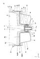
更に、容器21には、図4に示すように、ネック部24が設けられている。更に、ネック部24の先端には、注水口となる開封機構40が設けられている。この開封機構40は、ネック部24に取り付けられる容器コネクタ51と、容器コネクタ51内に配設される開封部材61とで構成されている。
<Opening mechanism>
Furthermore, the container 21 is provided with a neck portion 24 as shown in FIG. Further, an opening mechanism 40 serving as a water inlet is provided at the tip of the neck portion 24. The opening mechanism 40 includes a container connector 51 attached to the neck portion 24 and an opening member 61 disposed in the container connector 51.
<容器コネクタ>
容器コネクタ51は、図4及び図5に示すように、有底筒状のコネクタ部52の基端部に、容器21の筒状のネック部24に固定するための取付部53が外側に張り出して形成されている。この取付部53は、コネクタ部52に一体に設けられ、コネクタ部52を覆うようにコネクタ部52の外周に設けられた筒状の第一筒状部53aと、第一筒状部53aの先端部に基端側に外折りに設けられた第二筒状部53bとで構成されている。第一筒状部53aの外径は、ネック部24の内径とほぼ同じ大きさに形成され、第二筒状部53bの内径は、ネック部24の外径とほぼ同じ大きさに形成されている。更に、第二筒状部53bの内周面には、ネック部24の外周面の先端部又は先端部近傍に形成されたネック側嵌合部24aと嵌合する取付部側嵌合部53cが形成されている。そして、容器コネクタ51は、容器コネクタ51の取付部53の第一筒状部53aと第二筒状部53bとの間の隙間に容器21のネック部24を差し込み、第一筒状部53aと第二筒状部53bとでネック部24を狭持した状態で、第二筒状部53bの取付部側嵌合部53cをネック部24のネック側嵌合部24aと嵌合させることで、容器21に固定される。
<Container connector>
As shown in FIGS. 4 and 5, the container connector 51 has an attachment portion 53 that protrudes outward from the base end portion of the bottomed cylindrical connector portion 52 to be fixed to the cylindrical neck portion 24 of the container 21. Is formed. The attachment portion 53 is provided integrally with the connector portion 52, and has a cylindrical first cylindrical portion 53a provided on the outer periphery of the connector portion 52 so as to cover the connector portion 52, and a distal end of the first cylindrical portion 53a. And a second cylindrical portion 53b provided on the base end side so as to be folded outward. The outer diameter of the first cylindrical portion 53a is formed to be approximately the same as the inner diameter of the neck portion 24, and the inner diameter of the second cylindrical portion 53b is formed to be approximately the same as the outer diameter of the neck portion 24. Yes. Further, on the inner peripheral surface of the second cylindrical portion 53b, there is an attachment portion side fitting portion 53c that fits with the neck side fitting portion 24a formed at or near the distal end portion of the outer peripheral surface of the neck portion 24. Is formed. And the container connector 51 inserts the neck part 24 of the container 21 in the clearance gap between the 1st cylindrical part 53a and the 2nd cylindrical part 53b of the attaching part 53 of the container connector 51, and the 1st cylindrical part 53a and By fitting the attachment portion side fitting portion 53c of the second cylindrical portion 53b with the neck side fitting portion 24a of the neck portion 24 in a state where the neck portion 24 is sandwiched between the second cylindrical portion 53b, It is fixed to the container 21.
また、有底筒状のコネクタ部52の底部は、開封部材61によって打ち抜かれる打抜部54となる。ここでは、打抜部54の周囲は、薄肉部54aが設けられており、開封部材61で打抜部54を打ち抜き易くなっている。更に、コネクタ部52の底部には、略中央部に容器21側に向けて凹状の凹部54bが設けられている。この凹部54bは、開封部材61がジョイント部材110によって押される際にジョイント部材110の先端部に形成された突破部115が収納される凹部65の逃げ部である。これにより、コネクタ部52の底部は、凹部65に干渉されることなく、開封部材61の刃部63と当接することが出来る。
Further, the bottom of the bottomed cylindrical connector portion 52 is a punched portion 54 that is punched by the opening member 61. Here, a thin portion 54 a is provided around the punched portion 54, and the punched portion 54 is easily punched by the opening member 61. Furthermore, a concave portion 54b is provided at the bottom of the connector portion 52 at a substantially central portion toward the container 21 side. The concave portion 54 b is a relief portion of the concave portion 65 in which the breakthrough portion 115 formed at the distal end portion of the joint member 110 is accommodated when the opening member 61 is pushed by the joint member 110. Thereby, the bottom part of the connector part 52 can contact | abut with the blade part 63 of the opening member 61, without interfering with the recessed part 65. FIG.
更に、コネクタ部52の内周面には、段差によって構成されたストッパ55が形成されている。このストッパ55は、開封部材61の突部66と係止されることで、開封部材61が容器21の打抜部54を打ち抜いた際に開封部材61が容器21の内部に抜脱しないように構成されている。
Further, a stopper 55 constituted by a step is formed on the inner peripheral surface of the connector portion 52. The stopper 55 is engaged with the protrusion 66 of the opening member 61 so that the opening member 61 does not pull out into the container 21 when the opening member 61 punches the punching portion 54 of the container 21. It is configured.
更に、コネクタ部52の内周面には、内側に張り出すように係止部56が形成されている。この係止部56は、例えば、コネクタ部52の内周面のストッパ55よりも基端側に、コネクタ部52の内側にリング状に突設されて凸リング状に設けられている。そして、係止部56は、開封部材61の筒状部62の外周面に形成された封止部68と係止することで、開封部材61が先端側からコネクタ部52の外部に抜脱しないようにする。
Furthermore, a locking portion 56 is formed on the inner peripheral surface of the connector portion 52 so as to project inward. For example, the locking portion 56 is provided in a convex ring shape so as to protrude in a ring shape on the inner side of the connector portion 52 on the proximal side of the stopper 55 on the inner peripheral surface of the connector portion 52. And the latching | locking part 56 latches with the sealing part 68 formed in the outer peripheral surface of the cylindrical part 62 of the unsealing member 61, and the unsealing member 61 does not pull out of the connector part 52 from the front end side. Like that.
更に、容器コネクタ51の取付部53の第二筒状部53bの先端側の先端面には、保護フィルム57が貼着されている。この保護フィルム57は、例えばタンパーエビデンスフィルム等であり、コネクタ部52及び開封部材61を塵埃や雑菌等から保護し、衛生状態を維持する。このような保護フィルム57は、例えば液体容器体20がジョイント部材110に取り付けられる際に、ジョイント部材110の突破部115によって切り裂かれる。ここで突破部115は、保護フィルム57にある程度の集中した圧力を付与することが出来るようになっていれば良く、例えば、先鋭状であっても先丸状であっても良く、突破部115によって保護フィルム57がと破断されるように構成される。従って、保護フィルム57が剥がされていないことや切り裂かれていないことを確認することで、使用者は、容器21が密封された状態から手が加えられていないことを容易に把握することが出来る。なお、保護フィルム57は、突破部115によって切り裂かれた後に容器コネクタ51や開封部材61に干渉しないように、配向性を有する材料で形成され、切り裂かれると、配向方向に沿って内側に折り曲げられ、容器コネクタ51や開封部材61から退避するようにしても良い。更に、保護フィルム57は、張力が付加された状態で取り付けられ、切り裂かれると、第二筒状部53bの縁部側に逃げて、容器コネクタ51や開封部材61から退避するようにしても良い。勿論、保護フィルム57の破断部には、ハーフカット等による易断部を設けても良い。
Further, a protective film 57 is attached to the distal end surface of the second cylindrical portion 53 b of the attachment portion 53 of the container connector 51. The protective film 57 is, for example, a tamper evidence film, and protects the connector portion 52 and the opening member 61 from dust, germs, and the like, and maintains a sanitary state. For example, when the liquid container body 20 is attached to the joint member 110, the protective film 57 is torn by the breakthrough portion 115 of the joint member 110. Here, the breakthrough portion 115 only needs to be able to apply a certain amount of concentrated pressure to the protective film 57. For example, the breakthrough portion 115 may be sharp or rounded. Thus, the protective film 57 is configured to be broken. Therefore, by confirming that the protective film 57 has not been peeled off or torn, the user can easily grasp that the container 21 has not been touched from the sealed state. . The protective film 57 is formed of a material having orientation so as not to interfere with the container connector 51 and the opening member 61 after being cut by the breakthrough portion 115. When the protective film 57 is cut, the protective film 57 is folded inward along the orientation direction. The container connector 51 and the opening member 61 may be retracted. Furthermore, the protective film 57 may be attached in a state where a tension is applied, and when it is torn, it may escape to the edge side of the second cylindrical portion 53b and retreat from the container connector 51 or the opening member 61. . Of course, an easily cut portion by half cut or the like may be provided at the break portion of the protective film 57.
<開封部材>
開封部材61は、図4及び図6に示すように、容器コネクタ51と別部材であり、容器コネクタ51の打抜部54を打ち抜いたときに容器21の内部に挿入される筒状部62と、容器21の打抜部54を打ち抜く刃部63と、ジョイント部材110と連通する連通部64とを有している。
<Opening member>
As shown in FIGS. 4 and 6, the opening member 61 is a separate member from the container connector 51, and a cylindrical portion 62 inserted into the container 21 when the punching portion 54 of the container connector 51 is punched. The blade portion 63 for punching the punching portion 54 of the container 21 and the communication portion 64 communicating with the joint member 110 are provided.
筒状部62は、外径が容器コネクタ51のコネクタ部52のストッパ55よりも基端側の内周面の内径とほぼ同じ大きさとなるように形成されており、コネクタ部52の軸方向に摺動可能にコネクタ部52内に収納されている。更に、筒状部62の基端部は、閉塞され、平坦に形成されている。
The cylindrical portion 62 is formed so that the outer diameter is substantially the same as the inner diameter of the inner peripheral surface on the proximal end side with respect to the stopper 55 of the connector portion 52 of the container connector 51, and in the axial direction of the connector portion 52. The connector part 52 is slidably accommodated. Further, the proximal end portion of the cylindrical portion 62 is closed and formed flat.
更に、筒状部62の基端面には、図7に示すように、その縁部に沿うように、容器21側に向けて先鋭状をなす刃部63が少なくとも一個形成されている。例えば、刃部63は、筒状部62の基端面の一部の領域の縁部W以外に複数個形成されている。これにより、打抜部54は、刃部63が形成された領域に対応する領域では刃部63によって打ち抜かれるが、刃部63が形成されていない領域に対応する領域では打ち抜かれることがなく、この打ち抜かれなかった領域がコネクタ部52と打抜部54とを連結する連結部となり、この連結部によって打抜部54が容器21内を浮遊することを防止することが出来る。なお、刃部63は、筒状部62の基端面の全ての縁部に亘って複数個形成されるようにしても良い。
Further, as shown in FIG. 7, at least one blade portion 63 that is sharpened toward the container 21 side is formed on the base end surface of the cylindrical portion 62 so as to follow the edge portion. For example, a plurality of blade portions 63 are formed other than the edge portion W of a partial region of the proximal end surface of the cylindrical portion 62. Thereby, the punching portion 54 is punched by the blade portion 63 in the region corresponding to the region where the blade portion 63 is formed, but is not punched in the region corresponding to the region where the blade portion 63 is not formed, The region that has not been punched becomes a connecting portion that connects the connector portion 52 and the punching portion 54, and the connecting portion can prevent the punching portion 54 from floating in the container 21. Note that a plurality of blade portions 63 may be formed across all the edge portions of the base end surface of the cylindrical portion 62.
このような刃部63は、開封部材61がジョイント部材110によって押されると、容器21側に移動し、容器コネクタ51の底部の打抜部54を打ち抜く。なお、容器コネクタ51には、薄肉部54aが形成され、打ち抜き易くなっているので、刃部63を設けなくても良い。
When the unsealing member 61 is pushed by the joint member 110, the blade portion 63 moves to the container 21 side and punches the punching portion 54 at the bottom of the container connector 51. In addition, since the thin part 54a is formed in the container connector 51 and it is easy to punch out, the blade part 63 does not need to be provided.
また、図4及び図6に示すように、筒状部62の基端面には、略中心部に容器21側に向けて凹状の凹部65が設けられている。この凹部65は、開封部材61がジョイント部材110によって押される際に、ジョイント部材110の先端面に形成された突破部115が収納される逃げ部である。これにより、筒状部62の基端面は、ジョイント部材110の突破部115に干渉されることなく、ジョイント部材110の先端面と密接させることが出来る。なお、ジョイント部材110の突破部115を凹部65に収納することで、ジョイント部材110と開封部材61との位置決めを行うようにしても良い。
As shown in FIGS. 4 and 6, the proximal end surface of the cylindrical portion 62 is provided with a concave portion 65 that is substantially centered toward the container 21 side. The recess 65 is an escape portion in which the breakthrough portion 115 formed on the front end surface of the joint member 110 is stored when the opening member 61 is pushed by the joint member 110. Thereby, the base end surface of the cylindrical portion 62 can be brought into close contact with the distal end surface of the joint member 110 without being interfered with the breakthrough portion 115 of the joint member 110. Note that the joint member 110 and the opening member 61 may be positioned by housing the breakthrough portion 115 of the joint member 110 in the recess 65.
また、筒状部62の外周面の先端部には、外側に張り出した突部66が連続又は断続的に形成されている。この突部66は、開封部材61がジョイント部材110によって押されてコネクタ部52内を容器21側に移動したときに、ストッパ55に係止されて、開封部材61の押し込み量を規制し、開封部材61が容器21内に抜脱しないようにする。なお、突部66の外径は、ジョイント部材110が開封部材61を押圧する押圧力を小さくする観点からコネクタ部52のストッパ55の内径より小さく設けるようにしても良く、コネクタ部52の内周面と開封部材61の外周面との隙間から液体漏れが発生しないように、コネクタ部52のストッパ55の内径とほぼ同じ大きさ又はやや大きく設けて、コネクタ部52のストッパ55の内周面に圧接するように設けても良い。
Further, a protruding portion 66 projecting outward is formed continuously or intermittently at the distal end portion of the outer peripheral surface of the cylindrical portion 62. The protrusion 66 is locked by the stopper 55 when the opening member 61 is pushed by the joint member 110 and moves to the container 21 side in the connector portion 52, and regulates the pushing amount of the opening member 61, thereby opening the opening. The member 61 is prevented from being pulled out into the container 21. Note that the outer diameter of the protrusion 66 may be smaller than the inner diameter of the stopper 55 of the connector part 52 from the viewpoint of reducing the pressing force with which the joint member 110 presses the opening member 61. In order to prevent liquid leakage from the gap between the surface and the outer peripheral surface of the unsealing member 61, the inner diameter of the stopper 55 of the connector portion 52 is set to be approximately the same as or slightly larger than the inner diameter of the stopper 55 of the connector portion 52. You may provide so that it may press-contact.
また、筒状部62の外周面の基端側には、外側に張り出した封止部67,68が設けられている。封止部67は、例えば、外側にリング状に少なくとも一個突設された凸リング部や、ゴムパッキン及びOリング等の別体の封止部材等で構成されており、筒状部62の外周部の基端部又は基端部近傍に設けられている。封止部68は、封止部67と同様に、例えば、外側にリング状に少なくとも一個突設された凸リング部や、ゴムパッキン及びOリング等の別体の封止部材等で構成されており、筒状部62の外周部の封止部67よりも先端側でコネクタ部52の係止部56が当接する位置よりも基端側の中途部に設けられている。そして、封止部67,68は、コネクタ部52の係止部56よりも基端側の内周面に圧接される。これにより、封止部67,68は、コネクタ部52の内周面と開封部材61の外周面との隙間から液体漏れが発生しないようにしている。更に、開封部材61は、封止部67,68によってコネクタ部52の内周面に圧入保持されることで、コネクタ部52の内部で暴れ、刃部63が欠損することが防止される。
Further, sealing portions 67 and 68 projecting outward are provided on the proximal end side of the outer peripheral surface of the cylindrical portion 62. The sealing portion 67 includes, for example, a convex ring portion that protrudes in a ring shape on the outside, a separate sealing member such as a rubber packing and an O-ring, and the like. It is provided in the base end part of the part or in the vicinity of the base end part. Similar to the sealing portion 67, the sealing portion 68 is configured by, for example, a convex ring portion that protrudes in a ring shape on the outside, or a separate sealing member such as a rubber packing and an O-ring. In addition, the cylindrical portion 62 is provided at a midway portion on the proximal end side from the position where the locking portion 56 of the connector portion 52 abuts on the distal end side of the sealing portion 67 on the outer peripheral portion of the cylindrical portion 62. And the sealing parts 67 and 68 are press-contacted to the internal peripheral surface of the base end side rather than the latching | locking part 56 of the connector part 52. FIG. Thus, the sealing portions 67 and 68 prevent liquid leakage from occurring between the inner peripheral surface of the connector portion 52 and the outer peripheral surface of the opening member 61. Further, the unsealing member 61 is press-fitted and held on the inner peripheral surface of the connector portion 52 by the sealing portions 67 and 68, so that the unraveling inside the connector portion 52 and the blade portion 63 are prevented from being lost.
また、筒状部62の側面部には、開口部69が複数個形成されており、内部には、容器21の内部とジョイント部材110とを連通する連通部64が形成されている。この開口部69は、筒状部62の側面部の全周に亘って等間隔に複数個形成されている。ここでは、開口部69は、筒状部62の側面部の全周に亘って等間隔に二個形成されている。なお、開口部69は、一個又は三個以上形成されるようにしても良く、非等間隔に形成されるようにしても良い。更に、開口部69は、筒状部62の軸方向において、封止部67,68間に配置されるように形成されている。そして、開口部69は、開封部材61が容器コネクタ51の底部の打抜部54を打ち抜いて容器21の内部に進入した際、容器21の内部の液体を取り込み、連通部64に導水し、ジョイント部材110に液体を供給する。
In addition, a plurality of openings 69 are formed in the side surface portion of the cylindrical portion 62, and a communication portion 64 that connects the inside of the container 21 and the joint member 110 is formed inside. A plurality of openings 69 are formed at equal intervals over the entire circumference of the side surface of the cylindrical portion 62. Here, two openings 69 are formed at equal intervals over the entire circumference of the side surface of the cylindrical portion 62. One or three or more openings 69 may be formed, or may be formed at non-uniform intervals. Further, the opening 69 is formed so as to be disposed between the sealing portions 67 and 68 in the axial direction of the cylindrical portion 62. When the opening member 61 punches the punched portion 54 at the bottom of the container connector 51 and enters the inside of the container 21, the opening 69 takes in the liquid inside the container 21, conducts water to the communicating portion 64, A liquid is supplied to the member 110.
以上のような開封機構40を組み立てるに当たっては、図4に示すように、容器コネクタ51のコネクタ部52の先端側から開封部材61の刃部63を挿入端として、開封部材61の全体がコネクタ部52内に入るまで挿入される。この後、容器コネクタ51は、取付部53の第二筒状部53bの先端面に、保護フィルム57が貼着される。そして、開封部材61が挿入された容器コネクタ51は、容器21のネック部24に取付部53が嵌合されて、容器21に固定される。なお、組立手順は、この順に限定されるものではない。
In assembling the opening mechanism 40 as described above, as shown in FIG. 4, the entire opening member 61 is a connector part with the blade part 63 of the opening member 61 as the insertion end from the distal end side of the connector part 52 of the container connector 51. It is inserted until it enters in 52. Thereafter, the protective film 57 is adhered to the distal end surface of the second cylindrical portion 53 b of the attachment portion 53 of the container connector 51. The container connector 51 into which the opening member 61 is inserted is fixed to the container 21 by fitting the attachment portion 53 to the neck portion 24 of the container 21. Note that the assembly procedure is not limited to this order.
<装着機構>
装着機構30は、図1に示すように、本体10の下部に形成された空間部11内に本体10の縦幅方向Xに摺動可能な摺動機構12の摺動板12a上に取り付けられている。そして、装着機構30は、液体容器体20が取り付けられる又は取り外される際、縦幅方向Xの一端側(外部側)に摺動されて、本体10の空間部11内から外部に引き出されて、液体容器体20が取り付けられる又は取り外される。その一方で、装着機構30は、液体容器体20が取り付けられた後に、縦幅方向Xの他端側(空間部11側)に摺動されて、本体10の空間部11内に収納される。
<Mounting mechanism>
As shown in FIG. 1, the mounting mechanism 30 is mounted on a sliding plate 12 a of a sliding mechanism 12 that can slide in a longitudinal width direction X of the main body 10 in a space portion 11 formed in the lower portion of the main body 10. ing. Then, when the liquid container body 20 is attached or removed, the mounting mechanism 30 is slid to one end side (external side) in the longitudinal width direction X, and is pulled out from the space 11 of the main body 10, The liquid container body 20 is attached or removed. On the other hand, the mounting mechanism 30 is slid to the other end side (space part 11 side) in the longitudinal width direction X after the liquid container body 20 is attached, and is stored in the space part 11 of the main body 10. .
具体的に、装着機構30は、図3に示すように、液体容器体20の開封機構40に嵌入されて接続されるジョイント部材110と、液体容器体20をジョイント部材110に対して位置決めして保持する位置決め保持機構70とを有している。
Specifically, as shown in FIG. 3, the mounting mechanism 30 positions the liquid container body 20 with respect to the joint member 110 and the joint member 110 that is inserted and connected to the opening mechanism 40 of the liquid container body 20. And a positioning and holding mechanism 70 for holding.
<位置決め保持機構>
位置決め保持機構70は、図3に示すように、ジョイント部材110を保持するジョイント保持部材80と、ジョイント保持部材80に着脱可能に設けられ、液体容器体20を位置決めして保持する容器保持部材90とを有している。
<Positioning and holding mechanism>
As shown in FIG. 3, the positioning and holding mechanism 70 is detachably provided on the joint holding member 80 that holds the joint member 110 and the joint holding member 80, and the container holding member 90 that positions and holds the liquid container body 20. And have.
<ジョイント保持部材>
ジョイント保持部材80は、図3に示すように、底面部80aと、底面部80aの全周に高さ方向Zの一端側に向けて突設された側壁部80bとを有し、上面が開口された平面視略矩形の箱状に形成されている。
<Joint holding member>
As shown in FIG. 3, the joint holding member 80 has a bottom surface portion 80a and a side wall portion 80b projecting toward one end side in the height direction Z on the entire circumference of the bottom surface portion 80a. It is formed in a box shape having a substantially rectangular shape in plan view.
更に、ジョイント保持部材80の底面部80aには、高さ方向Zの一端側に向けて突設された突部81と、突部81の周辺に突部81よりも一段低い低部82とが設けられている。更に、この突部81には、ジョイント部材110が貫通された状態で保持されている。
Further, the bottom surface portion 80 a of the joint holding member 80 has a protrusion 81 projecting toward one end side in the height direction Z, and a lower portion 82 that is one step lower than the protrusion 81 around the protrusion 81. Is provided. Further, the protrusion 81 holds the joint member 110 in a penetrating state.
このようなジョイント保持部材80は、図8に示すように、容器保持部材90が着脱可能に取り付けられているので、例えば液体容器体20がジョイント部材110から取り外された際に液体がジョイント保持部材80にこぼれても、容器保持部材90を取り外すことで、容易に液体を拭きとることが出来、従来よりも簡単に掃除をすることが出来る。更に、ジョイント保持部材80は、ジョイント保持部材80にこぼれた液体はジョイント部材110が取り付けられている突部81よりも一段低い低部82に溜るので、ジョイント部材110と突部81の間から漏水が発生することを防止することが出来る。更に、ジョイント保持部材80は、こぼれた液体が低部82に溜るので、容易に液体を拭きとることが出来、従来よりも簡単に掃除をすることが出来る。従って、当該給液装置1は、衛生状態を維持することが出来る。
As shown in FIG. 8, such a joint holding member 80 has a container holding member 90 detachably attached thereto, so that, for example, when the liquid container body 20 is removed from the joint member 110, the liquid is removed from the joint holding member 80. Even if it spills over 80, by removing the container holding member 90, the liquid can be easily wiped off and can be cleaned more easily than in the past. Further, since the liquid spilled on the joint holding member 80 is accumulated in the lower portion 82 that is one step lower than the protrusion 81 to which the joint member 110 is attached, the joint holding member 80 leaks water between the joint member 110 and the protrusion 81. Can be prevented. Furthermore, since the spilled liquid accumulates in the lower portion 82, the joint holding member 80 can easily wipe off the liquid and can be cleaned more easily than in the past. Therefore, the liquid supply apparatus 1 can maintain a sanitary state.
なお、ジョイント保持部材80は、突部81の上面にこぼれた液体が低部82により確実に流れるように、突部81の上面に、中央部から低部82に向けて次第に低くなるように、傾斜を設けるようにしても良い。更に、ジョイント保持部材80は、低部82にこぼれた液体が隅部にまとめて溜るように、低部82に、突部81側から側壁部80b側に向けて次第に低くなるように、傾斜を設けるようにしても良い。
It should be noted that the joint holding member 80 is gradually lowered from the central portion toward the low portion 82 on the upper surface of the protrusion 81 so that liquid spilled on the upper surface of the protrusion 81 flows reliably through the low portion 82. An inclination may be provided. Further, the joint holding member 80 is inclined so that the liquid spilled in the low portion 82 is collected in the corner portion and gradually decreases from the protruding portion 81 side to the side wall portion 80b side. You may make it provide.
更に、図3に示すように、ジョイント保持部材80の側壁部80bには、高さ方向Zの一端部に、フランジ部83が設けられている。このフランジ部83は、側壁部80bの高さ方向Zの一端部から外側に張り出すように設けられた第一壁部83aと、第一壁部83aの先端部から高さ方向Zの他端側に向けて設けられた第二壁部83bとで構成されている。第一壁部83aは、容器保持部材90がジョイント保持部材80に取り付けられる際に、容器保持部材90の底面部90aと当接され、容器保持部材90が載置される載置部となる。第二壁部83bは、容器保持部材90がジョイント保持部材80に取り付けられる際に、外周面が容器保持部材90の他端側側壁部90cの内周面と当接され、容器保持部材90をジョイント保持部材80に位置決めすると共に、容器保持部材90が高さ方向Zの他端側に摺動する際にガイドする。具体的には、第二壁部83bは、容器保持部材90の位置決め部91の貫通口92の軸線がジョイント保持部材80のジョイント部材110の軸線と略一致するように、容器保持部材90をジョイント保持部材80に位置決めする。すなわち、第二壁部83bは、容器保持部材90を位置決めする位置決め部として機能すると共に、容器保持部材90を摺動する際のガイド部として機能する。
Further, as shown in FIG. 3, a flange portion 83 is provided at one end portion in the height direction Z on the side wall portion 80 b of the joint holding member 80. The flange portion 83 includes a first wall portion 83a provided so as to project outward from one end portion in the height direction Z of the side wall portion 80b, and the other end in the height direction Z from the distal end portion of the first wall portion 83a. And a second wall portion 83b provided toward the side. When the container holding member 90 is attached to the joint holding member 80, the first wall 83a is brought into contact with the bottom surface portion 90a of the container holding member 90 and serves as a placement portion on which the container holding member 90 is placed. When the container holding member 90 is attached to the joint holding member 80, the second wall 83 b comes into contact with the inner peripheral surface of the other end side wall 90 c of the container holding member 90, and the container holding member 90 is While positioning to the joint holding member 80, it guides when the container holding member 90 slides to the other end side of the height direction Z. Specifically, the second wall portion 83b joints the container holding member 90 so that the axis of the through-hole 92 of the positioning portion 91 of the container holding member 90 substantially coincides with the axis of the joint member 110 of the joint holding member 80. Position to the holding member 80. That is, the second wall portion 83 b functions as a positioning portion that positions the container holding member 90 and also functions as a guide portion when sliding the container holding member 90.
なお、フランジ部83は、第二壁部83bを設けずに、第一壁部83aだけで構成されるようにしても良い。第一壁部83aだけで構成される場合であっても、容器保持部材90がジョイント保持部材80に取り付けられる際に、第一壁部83aの端部83cが、容器保持部材90の他端側側壁部90cの内周面と当接されることで、容器保持部材90をジョイント保持部材80に位置決めすると共に、容器保持部材90が高さ方向Zの他端側に摺動する際にガイドすることが出来る。
In addition, the flange part 83 may be comprised only by the 1st wall part 83a, without providing the 2nd wall part 83b. Even when the container holding member 90 is attached to the joint holding member 80, the end 83c of the first wall 83a is connected to the other end side of the container holding member 90 even when the container holding member 90 is attached to the joint holding member 90. The container holding member 90 is positioned on the joint holding member 80 by being brought into contact with the inner peripheral surface of the side wall 90c, and is guided when the container holding member 90 slides to the other end side in the height direction Z. I can do it.
<容器保持部材>
容器保持部材90は、図3に示すように、ジョイント保持部材80に着脱可能に設けられ、内部に液体容器体20を位置決めして保持する。
<Container holding member>
As shown in FIG. 3, the container holding member 90 is detachably provided on the joint holding member 80, and positions and holds the liquid container body 20 therein.
具体的に、図3に示すように、容器保持部材90は、ジョイント保持部材80と同様に、底面部90aと、底面部90aの全周に高さ方向Zの一端側に向けて突設された側壁部90bとを有し、上面が開口された平面視略矩形の箱状に形成されている。そして、容器保持部材90は、底面部90aと側壁部90bとから成る空間部に例えば液体容器体20の一部が収納される。
Specifically, as shown in FIG. 3, similarly to the joint holding member 80, the container holding member 90 protrudes toward the one end side in the height direction Z on the entire circumference of the bottom surface portion 90 a and the bottom surface portion 90 a. And a substantially rectangular box shape in plan view with an upper surface opened. In the container holding member 90, for example, a part of the liquid container body 20 is accommodated in a space formed by the bottom surface portion 90a and the side wall portion 90b.
更に、容器保持部材90の底面部90aには、高さ方向Zの他端側に向けて突設され、容器保持部材90内に液体容器体20が収納される際に、液体容器体20の開封機構40が収納される筒状の位置決め部91が設けられている。この位置決め部91は、高さ方向Zの一端及び他端の両端が開口されており、内部に貫通口92が形成されている。更に、位置決め部91は、容器保持部材90がジョイント保持部材80に取り付けられた際に、先端部がジョイント保持部材80の底面部80a(突部81)と当接するように設けられている。更に、位置決め部91は、内周面の大きさが、液体容器体20の開封機構40の外周面の大きさとほぼ同じとなるように設けられている。そして、位置決め部91は、容器保持部材90に液体容器体20が収納される際に、液体容器体20を位置決めする。具体的には、位置決め部91は、液体容器体20の開封機構40の軸線が位置決め部91の貫通口92の軸線と略一致するように、液体容器体20の開封機構40を位置決めする。更に、この位置決め部91には、液体容器体20の開封機構40が収納されるので、液体容器体20が容器保持部材90に収納された際に、収納箱22の一端面22aと容器保持部材90の底面部90aとを確実に当接させることが出来る。
Furthermore, the bottom surface portion 90 a of the container holding member 90 protrudes toward the other end side in the height direction Z, and when the liquid container body 20 is stored in the container holding member 90, the liquid container body 20 A cylindrical positioning portion 91 in which the opening mechanism 40 is accommodated is provided. The positioning portion 91 is open at one end and the other end in the height direction Z, and has a through-hole 92 formed therein. Further, the positioning portion 91 is provided such that the tip end portion comes into contact with the bottom surface portion 80 a (projecting portion 81) of the joint holding member 80 when the container holding member 90 is attached to the joint holding member 80. Further, the positioning portion 91 is provided so that the size of the inner peripheral surface is substantially the same as the size of the outer peripheral surface of the opening mechanism 40 of the liquid container body 20. The positioning unit 91 positions the liquid container body 20 when the liquid container body 20 is stored in the container holding member 90. Specifically, the positioning unit 91 positions the opening mechanism 40 of the liquid container body 20 so that the axis of the opening mechanism 40 of the liquid container body 20 substantially matches the axis of the through-hole 92 of the positioning unit 91. Further, since the opening mechanism 40 of the liquid container body 20 is accommodated in the positioning portion 91, when the liquid container body 20 is accommodated in the container holding member 90, the one end face 22a of the storage box 22 and the container holding member are accommodated. The bottom surface portion 90a of the 90 can be reliably brought into contact.
更に、容器保持部材90の側壁部90bは、例えば液体容器体20(収納箱22)と平面視でほぼ同じ大きさ又はやや大きくなるように形成されており、液体容器体20を容器保持部材90に大まかに位置決めすると共に、液体容器体20が高さ方向Zの他端側に摺動する際にガイドする。すなわち、側壁部90bは、液体容器体20を位置決めする位置決め部として機能すると共に、液体容器体20を摺動する際のガイド部として機能する。
Furthermore, the side wall portion 90b of the container holding member 90 is formed to be, for example, substantially the same size or slightly larger in plan view than the liquid container body 20 (storage box 22). And is guided when the liquid container body 20 slides to the other end side in the height direction Z. That is, the side wall part 90 b functions as a positioning part for positioning the liquid container body 20 and also functions as a guide part when sliding the liquid container body 20.
更に、容器保持部材90は、側壁部90bの内周面に、リブ(不図示)が少なくとも一個形成されている。このリブには、容器保持部材90内に保持された液体容器体20の収納箱22に噛み込む返し部が設けられている。更に、この返し部は、収納箱22に噛み込む係止力が容器保持部材90とジョイント保持部材80との間の嵌合力よりもやや小さくなるように、設けられている。従って、容器保持部材90内に保持された液体容器体20は、収納箱22と返し部との間の係止力以上で容器保持部材90とジョイント保持部材80との間の嵌合力以下の力で高さ方向Zの一端側に持ち上げることで、容器保持部材90をジョイント保持部材80から離脱させることなく、容器保持部材90から離脱させることが出来る。更に、容器保持部材90は、容器保持部材90とジョイント保持部材80との間の嵌合力以上の力で高さ方向Zの一端側に持ち上げられると、ジョイント保持部材80から離脱させることが出来る。
Further, the container holding member 90 has at least one rib (not shown) formed on the inner peripheral surface of the side wall 90b. The rib is provided with a return portion that bites into the storage box 22 of the liquid container body 20 held in the container holding member 90. Further, the return portion is provided so that the locking force biting into the storage box 22 is slightly smaller than the fitting force between the container holding member 90 and the joint holding member 80. Accordingly, the liquid container body 20 held in the container holding member 90 has a force that is greater than the locking force between the storage box 22 and the return portion and less than the fitting force between the container holding member 90 and the joint holding member 80. Thus, the container holding member 90 can be detached from the container holding member 90 without being separated from the joint holding member 80 by being lifted to one end side in the height direction Z. Furthermore, the container holding member 90 can be detached from the joint holding member 80 when it is lifted to one end in the height direction Z by a force greater than the fitting force between the container holding member 90 and the joint holding member 80.
更に、側壁部90bの高さ方向Zの一端部には、使用者が把持する把持部94が設けられている。この把持部94は、例えば、側壁部90bの高さ方向Zの一端部を外側に折り曲げた折曲部で構成さている。従って、容器保持部材90は、ジョイント保持部材80から離脱させてジョイント保持部材80に溜った液体等を拭きとり掃除する際に、使用者が把持部94を把持することで、容易に高さ方向Zの一端側に引き上げることが出来る。なお、把持部94は、折曲部で構成されることに限定されるものではなく、使用者が容器保持部材90を把持することが出来れば、従来公知の如何なる構成であっても良く、例えば、底面部90aや側壁部90bに形成された使用者の指等が挿入可能な貫通口で構成されるようにしても良い。
Furthermore, a grip portion 94 that is gripped by the user is provided at one end portion in the height direction Z of the side wall portion 90b. For example, the grip portion 94 includes a bent portion in which one end portion in the height direction Z of the side wall portion 90b is bent outward. Therefore, when the container holding member 90 is separated from the joint holding member 80 and wipes and cleans the liquid accumulated in the joint holding member 80, the user can easily hold the holding portion 94 in the height direction. It can be pulled up to one end of Z. Note that the grip portion 94 is not limited to be formed of a bent portion, and may be any conventionally known configuration as long as the user can grip the container holding member 90. For example, In addition, a user's finger or the like formed on the bottom surface portion 90a or the side wall portion 90b may be configured as a through-hole that can be inserted.
更に、容器保持部材90は、底面部90aの全周に高さ方向Zの他端側に向けて突設された他端側側壁部90cを有している。他端側側壁部90cは、平面視した際、内周面の形状及び大きさがジョイント保持部材80のフランジ部83とほぼ同じ形状及び大きさになるように設けられている。そして、他端側側壁部90cは、容器保持部材90がジョイント保持部材80に取り付けられる際に、ジョイント保持部材80のフランジ部83の第二壁部83bの外周面が内周面に当接され、容器保持部材90がジョイント保持部材80に位置決めされると共に、容器保持部材90が高さ方向Zの他端側に摺動する際にガイドされる。
Furthermore, the container holding member 90 has the other end side wall portion 90c that protrudes toward the other end side in the height direction Z on the entire circumference of the bottom surface portion 90a. The other end side wall portion 90c is provided such that the shape and size of the inner peripheral surface thereof are substantially the same shape and size as the flange portion 83 of the joint holding member 80 when viewed in plan. Then, when the container holding member 90 is attached to the joint holding member 80, the outer peripheral surface of the second wall 83b of the flange portion 83 of the joint holding member 80 is brought into contact with the inner peripheral surface of the other end side wall 90c. The container holding member 90 is positioned on the joint holding member 80 and is guided when the container holding member 90 slides to the other end side in the height direction Z.
<ジョイント部材>
ジョイント部材110は、図4に示すように、内部に通水路111aが形成されると共に、側面部に通水路111aと連通する取込開口部111bが形成された筒状部111と、筒状部111の軸方向に摺動可能に設けられ、取込開口部111bを覆うと共に露出させるシャッタ部112と、液体容器体20が未装着時にシャッタ部112が取込開口部111bを覆うように付勢する付勢部113とを有している。
<Joint material>
As shown in FIG. 4, the joint member 110 includes a tubular portion 111 in which a water passage 111 a is formed and a side surface portion is formed with an intake opening 111 b communicating with the water passage 111 a. 111 is slidable in the axial direction of 111, and covers and exposes the intake opening 111b, and urges the shutter 112 to cover the intake opening 111b when the liquid container body 20 is not attached. And an urging portion 113 that performs the above operation.
筒状部111は、筒状に形成されており、内部に通水路111aが形成されている。更に、筒状部111は、図3に示すように、装着機構30のジョイント保持部材80の底面部80aに立設されて設けられている。
The tubular portion 111 is formed in a tubular shape, and a water passage 111a is formed inside. Further, as shown in FIG. 3, the cylindrical portion 111 is provided upright on the bottom surface portion 80 a of the joint holding member 80 of the mounting mechanism 30.
また、筒状部111の側面部の先端側には、図4及び図9に示すように、外側に張り出したフランジ部114が形成されている。このフランジ部114は、外径が開封部材61の筒状部62の内径とほぼ同じ大きさとなるように形成されている。そして、フランジ部114は、ジョイント部材110が開封部材61の筒状部62内に差し込まれた際に、開封部材61の筒状部62の内周面に圧接される。更に、筒状部111の側面部の先端側には、フランジ部114よりも基端側に、取込開口部111bが複数個形成されている。例えば、取込開口部111bは、筒状部111の側面部に等間隔に二個形成されている。なお、取込開口部111bは、筒状部111の側面部に一個又は三個以上形成されるようにしても良く、非等間隔に形成されるようにしても良い。
Further, as shown in FIGS. 4 and 9, a flange portion 114 projecting outward is formed on the distal end side of the side surface portion of the cylindrical portion 111. The flange portion 114 is formed so that the outer diameter is substantially the same as the inner diameter of the cylindrical portion 62 of the opening member 61. The flange portion 114 is in pressure contact with the inner peripheral surface of the tubular portion 62 of the opening member 61 when the joint member 110 is inserted into the tubular portion 62 of the opening member 61. Further, a plurality of intake openings 111 b are formed on the distal end side of the side surface portion of the cylindrical portion 111 on the proximal end side with respect to the flange portion 114. For example, two intake openings 111 b are formed at equal intervals on the side surface of the cylindrical portion 111. Note that one or three or more intake openings 111b may be formed on the side surface of the cylindrical portion 111, or may be formed at unequal intervals.
更に、筒状部111の先端面には、先端が先鋭な突破部115が形成されている。従って、液体容器体20をジョイント部材110に取り付ける際に、この突破部115によって保護フィルム57を切り裂くことが出来るので、容器コネクタ51から保護フィルム57を剥がす工程を省略することが出来る。
Further, a breakthrough portion 115 having a sharp tip is formed on the tip surface of the cylindrical portion 111. Therefore, when the liquid container body 20 is attached to the joint member 110, the protective film 57 can be cut off by the breakthrough portion 115, so that the step of peeling the protective film 57 from the container connector 51 can be omitted.
シャッタ部112は、図4及び図9に示すように、筒状に形成されており、筒状部111の外周上に筒状部111の軸方向に摺動可能に設けられている。更に、シャッタ部112は、外径が開封部材61の筒状部62の内径とほぼ同じ大きさとなるように形成されている。これにより、シャッタ部112は、開封部材61の筒状部62内に隙間無く圧入され、シャッタ部112と開封部材61の間から漏水が発生することを防止することが出来る。
As shown in FIGS. 4 and 9, the shutter portion 112 is formed in a cylindrical shape, and is provided on the outer periphery of the cylindrical portion 111 so as to be slidable in the axial direction of the cylindrical portion 111. Furthermore, the shutter portion 112 is formed so that the outer diameter is substantially the same as the inner diameter of the cylindrical portion 62 of the opening member 61. As a result, the shutter portion 112 is press-fitted into the cylindrical portion 62 of the opening member 61 without any gap, and leakage of water from between the shutter portion 112 and the opening member 61 can be prevented.
また、シャッタ部112の外周面の基端部には、外側に張り出した突部116が連続又は断続的に形成されている。突部116は、シャッタ部112が開封部材61の筒状部62内に挿入されると、開封部材61の筒状部62の基端面に係止される。そして、シャッタ部112は、液体容器体20がジョイント部材110の基端側に移動されると、付勢部113の付勢力に抗して基端側に移動されて、図9(A)に示すように、筒状部111の取込開口部111bを露出させる。その一方で、シャッタ部112は、液体容器体20をジョイント部材110から取り外す等、液体容器体20がジョイント部材110の先端側に移動されると、付勢部113の付勢力によって先端側に移動されて、図9(B)に示すように、筒状部111の取込開口部111bを覆う。
In addition, a protrusion 116 protruding outward is continuously or intermittently formed at the proximal end portion of the outer peripheral surface of the shutter portion 112. When the shutter portion 112 is inserted into the cylindrical portion 62 of the opening member 61, the protrusion 116 is locked to the base end surface of the cylindrical portion 62 of the opening member 61. Then, when the liquid container body 20 is moved to the proximal end side of the joint member 110, the shutter portion 112 is moved to the proximal end side against the urging force of the urging portion 113, as shown in FIG. As shown, the intake opening 111b of the cylindrical portion 111 is exposed. On the other hand, when the liquid container body 20 is moved to the distal end side of the joint member 110 such as removing the liquid container body 20 from the joint member 110, the shutter section 112 moves to the distal end side by the urging force of the urging portion 113. Then, as shown in FIG. 9B, the intake opening 111b of the cylindrical portion 111 is covered.
また、図4及び図9に示すように、シャッタ部112の外周面の先端部には、外側に張り出すように封止部117が設けられている。この封止部117は、例えば、外側にリング状に少なくとも1個突設された凸リング部や、ゴムパッキン及びOリング等の別体の封止部材等で構成されており、シャッタ部112の外周面の先端部に設けられている。そして、封止部117は、シャッタ部112が開封部材61の筒状部62内に挿入されると、開封部材61の筒状部62の内周面に圧接される。これにより、封止部117は、開封部材61の筒状部62の内周面とシャッタ部112の外周面との隙間から液体漏れが発生しないようにしている。
As shown in FIGS. 4 and 9, a sealing portion 117 is provided at the distal end portion of the outer peripheral surface of the shutter portion 112 so as to protrude outward. The sealing portion 117 is composed of, for example, a convex ring portion that protrudes in a ring shape on the outside, a separate sealing member such as a rubber packing and an O-ring, and the like. It is provided in the front-end | tip part of an outer peripheral surface. The sealing portion 117 is pressed against the inner peripheral surface of the cylindrical portion 62 of the opening member 61 when the shutter portion 112 is inserted into the cylindrical portion 62 of the opening member 61. As a result, the sealing portion 117 prevents liquid leakage from the gap between the inner peripheral surface of the cylindrical portion 62 of the opening member 61 and the outer peripheral surface of the shutter portion 112.
付勢部113は、図3に示すように、例えば圧縮バネ又は永久磁石等で構成されており、筒状部111の外周上のジョイント保持部材80の底面部80aとシャッタ部112の基端面との間に配設されている。付勢部113は、液体容器体20がジョイント部材110に未装着の際やジョイント部材110から取り外される際に、シャッタ部112の先端面が筒状部111のフランジ部114の基端面と当接して、シャッタ部112が筒状部111の取込開口部111bを覆うように、シャッタ部112を先端部(フランジ部114)側に付勢する。
As shown in FIG. 3, the urging portion 113 is composed of, for example, a compression spring or a permanent magnet, and includes a bottom surface portion 80 a of the joint holding member 80 on the outer periphery of the cylindrical portion 111 and a base end surface of the shutter portion 112. Between the two. When the liquid container body 20 is not attached to the joint member 110 or is removed from the joint member 110, the urging portion 113 is in contact with the proximal end surface of the flange portion 114 of the tubular portion 111 when the shutter portion 112 is removed. Thus, the shutter portion 112 is biased toward the distal end portion (flange portion 114) so that the shutter portion 112 covers the intake opening 111b of the cylindrical portion 111.
<取付方法>
次に、以上のような構成を有する給液装置1において、液体容器体20を装着機構30に取り付ける取付方法について説明する。
<Mounting method>
Next, an attachment method for attaching the liquid container body 20 to the attachment mechanism 30 in the liquid supply apparatus 1 having the above configuration will be described.
先ず、図1に示すように、当該給液装置1は、本体10の摺動機構12が縦幅方向Xの一端側(外部側)に摺動されて、装着機構30が本体10の空間部11内から外部に引き出される。
First, as shown in FIG. 1, in the liquid supply apparatus 1, the sliding mechanism 12 of the main body 10 is slid to one end side (external side) in the vertical width direction X, and the mounting mechanism 30 is a space portion of the main body 10. 11 is pulled out from the inside.
次いで、当該給液装置1は、図1に示すように、液体容器体20が、容器21が収納箱22に収納されたままの状態で、収納箱22の開封機構40側の一端面22aを挿入端として、液体容器体20の開封機構40を容器保持部材90の位置決め部91に挿入しつつ、装着機構30の容器保持部材90内に挿入される。当該給液装置1は、図10に示すように、液体容器体20の開封機構40が容器保持部材90の位置決め部91内に収納されて、図14に示すように、液体容器体20の収納箱22の一端面22aと容器保持部材90の底面部90aとが当接するまで、液体容器体20が装着機構30の容器保持部材90内に挿入される。
Next, as shown in FIG. 1, the liquid supply apparatus 1 is configured so that the liquid container body 20 has an end surface 22 a on the opening mechanism 40 side of the storage box 22 while the container 21 is stored in the storage box 22. As an insertion end, the opening mechanism 40 of the liquid container body 20 is inserted into the container holding member 90 of the mounting mechanism 30 while being inserted into the positioning portion 91 of the container holding member 90. 10, the unsealing mechanism 40 of the liquid container body 20 is housed in the positioning portion 91 of the container holding member 90, and the liquid container body 20 is housed as shown in FIG. The liquid container body 20 is inserted into the container holding member 90 of the mounting mechanism 30 until the one end surface 22a of the box 22 and the bottom surface portion 90a of the container holding member 90 abut.
この際、当該給液装置1は、図10に示すように、先ず、液体容器体20が容器保持部材90内に挿入されて、液体容器体20の開封機構40が容器保持部材90の位置決め部91内に収納されると、図11に示すように、ジョイント部材110の突破部115によって、液体容器体20の保護フィルム57が切り裂かれる。従って、当該給液装置1は、液体容器体20の容器21から保護フィルム57を剥がす工程を省略することが出来る。なお、当該給液装置1は、液体容器体20を容器保持部材90内に挿入する前に、保護フィルム57を剥がしておくようにしても良い。
At this time, as shown in FIG. 10, the liquid supply apparatus 1 is configured such that the liquid container body 20 is first inserted into the container holding member 90, and the opening mechanism 40 of the liquid container body 20 is positioned by the positioning portion of the container holding member 90. When housed in 91, as shown in FIG. 11, the protective film 57 of the liquid container body 20 is torn by the breakthrough portion 115 of the joint member 110. Therefore, the liquid supply apparatus 1 can omit the step of peeling the protective film 57 from the container 21 of the liquid container body 20. The liquid supply apparatus 1 may peel off the protective film 57 before inserting the liquid container body 20 into the container holding member 90.
次いで、当該給液装置1は、さらに液体容器体20が高さ方向Zの他端側に移動されると、図12に示すように、ジョイント部材110のシャッタ部112が、シャッタ部112の突部116と開封部材61の筒状部62の基端面とが係止されるまで、開封部材61内に差し込まれる。この際、ジョイント部材110は、シャッタ部112が開封部材61内に隙間無く圧入され、ジョイント部材110と開封部材61の間から漏水が発生することを防止することが出来る。
Next, when the liquid container body 20 is further moved to the other end side in the height direction Z, the liquid supply device 1 causes the shutter portion 112 of the joint member 110 to protrude from the shutter portion 112 as shown in FIG. It is inserted into the opening member 61 until the portion 116 and the proximal end surface of the cylindrical portion 62 of the opening member 61 are locked. At this time, the joint member 110 can prevent the shutter portion 112 from being press-fitted into the opening member 61 without a gap, and leakage of water from between the joint member 110 and the opening member 61 can be prevented.
次いで、当該給液装置1は、さらに液体容器体20が高さ方向Zの他端側に移動されると、図13に示すように、シャッタ部112が付勢部113の付勢力に抗して基端側に移動され、開封部材61内で筒状部111の取込開口部111bが露出される。
Next, in the liquid supply apparatus 1, when the liquid container body 20 is further moved to the other end side in the height direction Z, the shutter portion 112 resists the urging force of the urging portion 113 as shown in FIG. Then, the intake opening 111b of the cylindrical portion 111 is exposed in the opening member 61.
次いで、図14に示すように、当該給液装置1は、さらに液体容器体20が高さ方向Zの他端側に移動されて、液体容器体20の収納箱22の一端面22aと容器保持部材90の底面部90aとが当接されると、図15に示すように、容器コネクタ51が高さ方向Zの他端側に移動されるのに伴って、ジョイント部材110の開封部材61の刃部63が容器コネクタ51の底部の打抜部54を打ち抜く。そして、当該給液装置1は、ジョイント部材110の筒状部111の取込開口部111bがコネクタ部52から露出される。これにより、液体容器体20の容器21の内部と開封部材61の開口部69とジョイント部材110の筒状部111の取込開口部111bと通水路111aとが連通する。これにより、容器21の液体は、容器コネクタ51及びジョイント部材110を介して給液装置1に供給される。
Next, as shown in FIG. 14, in the liquid supply apparatus 1, the liquid container body 20 is further moved to the other end side in the height direction Z, and the one end face 22 a of the storage box 22 of the liquid container body 20 and the container holding When the bottom surface portion 90a of the member 90 is brought into contact, as shown in FIG. 15, the container connector 51 is moved to the other end side in the height direction Z and the opening member 61 of the joint member 110 is moved. The blade part 63 punches the punching part 54 at the bottom of the container connector 51. In the liquid supply apparatus 1, the intake opening 111 b of the cylindrical portion 111 of the joint member 110 is exposed from the connector portion 52. Thereby, the inside of the container 21 of the liquid container body 20, the opening 69 of the opening member 61, the intake opening 111b of the tubular portion 111 of the joint member 110, and the water passage 111a communicate with each other. Thereby, the liquid in the container 21 is supplied to the liquid supply apparatus 1 via the container connector 51 and the joint member 110.
以上のようにして、当該給液装置1は、液体容器体20を装着機構30に取り付けることが出来る。
As described above, the liquid supply apparatus 1 can attach the liquid container body 20 to the mounting mechanism 30.
<取外方法>
次に、以上のような構成を有する給液装置1において、液体容器体20を装着機構30から取り外す取外方法について説明する。
<Removal method>
Next, a method of removing the liquid container body 20 from the mounting mechanism 30 in the liquid supply apparatus 1 having the above configuration will be described.
先ず、図16に示すように、当該給液装置1は、液体容器体20が使用者によって液体容器体20が装着機構30に装着された状態から高さ方向Zの一端側に持ち上げられると、図17に示すように、開封機構40のコネクタ部52が高さ方向Zの一端側に移動されて、開封機構40の開封部材61がコネクタ部52内に収納される。
First, as shown in FIG. 16, when the liquid container body 20 is lifted to one end side in the height direction Z from the state in which the liquid container body 20 is mounted on the mounting mechanism 30 by the user, As shown in FIG. 17, the connector portion 52 of the opening mechanism 40 is moved to one end side in the height direction Z, and the opening member 61 of the opening mechanism 40 is accommodated in the connector portion 52.
次いで、当該給液装置1は、さらに液体容器体20が高さ方向Zの一端側に移動されると、図18に示すように、シャッタ部112が付勢部113の付勢力によって高さ方向Zの一端側に移動されて、シャッタ部112によって開封部材61内で筒状部111の取込開口部111bが覆われる。
Next, when the liquid container body 20 is further moved to one end side in the height direction Z, the liquid supply device 1 is moved in the height direction by the urging force of the urging portion 113 as shown in FIG. It moves to the one end side of Z, and the opening part 111b of the cylindrical part 111 is covered in the opening member 61 by the shutter part 112.
次いで、当該給液装置1は、さらに液体容器体20が高さ方向Zの一端側に移動されると、図19に示すように、シャッタ部112が開封部材61内から取り出され、シャッタ部112の突部116と開封部材61の筒状部62の基端面との係止状態が解除され、開封機構40がジョイント部材110から離脱する。
Next, when the liquid container body 20 is further moved to one end side in the height direction Z, the liquid supply device 1 takes out the shutter portion 112 from the opening member 61 as shown in FIG. The protruding state 116 and the proximal end surface of the cylindrical portion 62 of the opening member 61 are released, and the opening mechanism 40 is detached from the joint member 110.
次いで、図20に示すように、当該給液装置1は、さらに液体容器体20が高さ方向Zの一端側に持ち上げられると、液体容器体20が容器保持部材90内から取り出され、液体容器体20が装着機構30から離脱する。
Next, as shown in FIG. 20, when the liquid container body 20 is further lifted to one end side in the height direction Z, the liquid container body 20 is taken out from the container holding member 90, and the liquid container body 20 The body 20 is detached from the mounting mechanism 30.
以上のようにして、当該給液装置1は、液体容器体20を装着機構30から取り外すことが出来る。
As described above, the liquid supply apparatus 1 can remove the liquid container body 20 from the mounting mechanism 30.
<作用効果>
以上のように、本発明を適用した給液装置1は、容器コネクタ51のコネクタ部52内に収納された開封部材61がジョイント部材110の挿入ガイド部として機能することから、ジョイント部材110が漏水を防止することが出来る。すなわち、給液装置1は、液体が満杯に入った重い容器21を有する液体容器体20を、容易に正しく装着機構30に装着することが出来る。
<Effect>
As described above, in the liquid supply apparatus 1 to which the present invention is applied, since the unsealing member 61 housed in the connector portion 52 of the container connector 51 functions as an insertion guide portion of the joint member 110, the joint member 110 leaks water. Can be prevented. That is, the liquid supply apparatus 1 can easily and correctly mount the liquid container body 20 having the heavy container 21 filled with the liquid to the mounting mechanism 30.
また、給液装置1は、容器保持部材90がジョイント保持部材80に着脱可能に設けられているので、図8に示すように、容器保持部材90をジョイント保持部材80から取り外すことが出来るので、容器保持部材90に液体容器体20の開封機構40を収納する筒状の位置決め部91が設けられていても、容器保持部材90の位置決め部91内、ジョイント部材110及びジョイント保持部材80に付着した液体や塵埃や雑菌等を容易に拭きとることが出来、簡単に掃除することが出来る。従って、当該給液装置1は、従来よりも容易に衛生状態を維持することが出来る。
Moreover, since the container holding member 90 is detachably provided on the joint holding member 80 in the liquid supply apparatus 1, the container holding member 90 can be detached from the joint holding member 80 as shown in FIG. Even if the container holding member 90 is provided with the cylindrical positioning portion 91 that accommodates the opening mechanism 40 of the liquid container body 20, the container holding member 90 adheres to the joint member 110 and the joint holding member 80 in the positioning portion 91 of the container holding member 90. Liquids, dust, germs, etc. can be easily wiped off and can be easily cleaned. Therefore, the liquid supply apparatus 1 can maintain a sanitary state more easily than in the past.
更に、給液装置1は、ジョイント保持部材80の底面部80aに、ジョイント部材110が取り付けられた突部81の周辺に突部81よりも一段低い低部82が設けられており、液体容器体20がジョイント部材110から取り外された際に、こぼれた液体がこの低部82に溜るので、ジョイント部材110と突部81との間から漏水が発生することを防止することが出来る。更に、給液装置1は、こぼれた液体が低部82にまとめて溜るので、従来の給液装置よりも、容易に液体を拭きとることが出来、従来よりも簡単に掃除をすることが出来る。従って、当該給液装置1は、従来よりも容易に衛生状態を維持することが出来る。
Furthermore, the liquid supply apparatus 1 is provided with a lower portion 82 that is one step lower than the protrusion 81 around the protrusion 81 to which the joint member 110 is attached, on the bottom surface portion 80a of the joint holding member 80. When 20 is removed from the joint member 110, spilled liquid accumulates in the low portion 82, so that leakage of water between the joint member 110 and the protrusion 81 can be prevented. Furthermore, since the liquid supply apparatus 1 collects the spilled liquid in the lower portion 82, the liquid supply apparatus 1 can wipe off the liquid more easily than the conventional liquid supply apparatus and can be cleaned more easily than the conventional liquid supply apparatus. . Therefore, the liquid supply apparatus 1 can maintain a sanitary state more easily than in the past.
また、給液装置1は、ジョイント保持部材80の側壁部80bのフランジ部83の外周面と容器保持部材90の他端側側壁部90cの内周面とが当接することによって、ジョイント保持部材80のジョイント部材110の軸線と容器保持部材90の位置決め部91の貫通口92の軸線とが略一致するように位置決めされている。更に、給液装置1は、液体容器体20が、容器21が収納箱22に収納されたままの状態で、収納箱22の開封機構40側の一端面22aを挿入端として、液体容器体20の開封機構40を容器保持部材90の位置決め部91に挿入しつつ、装着機構30の容器保持部材90内に挿入されると、容器保持部材90の位置決め部91によって、液体容器体20の開封機構40の軸線と容器保持部材90の位置決め部91の貫通口92の軸線とが略一致するように位置決めされる。すなわち、給液装置1は、液体容器体20の開封機構40が容器保持部材90の位置決め部91内に収納されると、液体容器体20の開封機構40の軸線とジョイント保持部材80のジョイント部材110の軸線とが略一致するように位置決めされる。従って、給液装置1は、液体容器体20を、容器21が収納箱22に収納されたままの状態で、収納箱22の開封機構40側の一端面22aを挿入端として、液体容器体20の開封機構40を容器保持部材90の位置決め部91に挿入しつつ、装着機構30の容器保持部材90内に挿入するといった簡単な動作を行うことで、液体容器体20の開封機構40の軸線とジョイント保持部材80のジョイント部材110の軸線とが略一致するように配置することが出来、液体容器体20を容易に正しく装着機構30に装着することが出来る。
Further, the liquid supply apparatus 1 is configured such that the outer peripheral surface of the flange portion 83 of the side wall portion 80b of the joint holding member 80 and the inner peripheral surface of the other end side wall portion 90c of the container holding member 90 come into contact with each other. The axis of the joint member 110 and the axis of the through-hole 92 of the positioning portion 91 of the container holding member 90 are positioned so as to substantially coincide with each other. Furthermore, the liquid supply apparatus 1 is configured such that the liquid container body 20 is in a state where the container 21 is stored in the storage box 22, and the one end surface 22 a on the opening mechanism 40 side of the storage box 22 is used as an insertion end. When the unsealing mechanism 40 is inserted into the container holding member 90 of the mounting mechanism 30 while being inserted into the positioning portion 91 of the container holding member 90, the opening mechanism of the liquid container body 20 is inserted by the positioning portion 91 of the container holding member 90. The positioning is performed so that the 40 axis and the axis of the through-hole 92 of the positioning portion 91 of the container holding member 90 substantially coincide with each other. That is, in the liquid supply apparatus 1, when the opening mechanism 40 of the liquid container body 20 is accommodated in the positioning portion 91 of the container holding member 90, the axis of the opening mechanism 40 of the liquid container body 20 and the joint member of the joint holding member 80. Positioning is performed so that the axis of 110 substantially matches. Therefore, the liquid supply apparatus 1 uses the liquid container body 20 with the one end face 22a on the side of the opening mechanism 40 of the storage box 22 as the insertion end while the container 21 is still stored in the storage box 22. The opening mechanism 40 is inserted into the positioning portion 91 of the container holding member 90 while being inserted into the container holding member 90 of the mounting mechanism 30, so that the axis of the opening mechanism 40 of the liquid container body 20 The joint holding member 80 can be arranged so that the axis of the joint member 110 substantially coincides, and the liquid container body 20 can be easily and correctly mounted on the mounting mechanism 30.
更に、給液装置1は、液体容器体20が容器保持部材90内に挿入され、液体容器体20の開封機構40が容器保持部材90の位置決め部91内に収納されると、液体容器体20の開封機構40の軸線と容器保持部材90の位置決め部91の貫通口92の軸線とが略一致するように位置決めされるので、例えば液体容器体20の収納箱22が輸送時や保管時に潰れる等の変形等しても、液体容器体20の開封機構40の軸線と容器保持部材90の位置決め部91の貫通口92の軸線とが略一致するように位置決めすることが出来、液体容器体20を容易に正しく装着機構30に装着することが出来る。
Further, in the liquid supply apparatus 1, when the liquid container body 20 is inserted into the container holding member 90 and the opening mechanism 40 of the liquid container body 20 is stored in the positioning portion 91 of the container holding member 90, the liquid container body 20. Is positioned so that the axis of the unsealing mechanism 40 and the axis of the through-hole 92 of the positioning portion 91 of the container holding member 90 substantially coincide with each other, for example, the storage box 22 of the liquid container body 20 is crushed during transportation or storage. Can be positioned so that the axis of the opening mechanism 40 of the liquid container body 20 and the axis of the through-hole 92 of the positioning portion 91 of the container holding member 90 substantially coincide with each other. The mounting mechanism 30 can be easily and correctly mounted.
また、給液装置1は、液体容器体20の未装着時において、ジョイント部材110の筒状部111の取込開口部111bがシャッタ部112によって覆われている。更に、ジョイント部材110は、液体容器体20が取り付けられる際、シャッタ部112が開封部材61内に差し込まれた後に、開封部材61内で筒状部111の取込開口部111bを露出させる動作が行われる。更に、ジョイント部材110は、液体容器体20が取り外される際、シャッタ部112が開封部材61内に差し込まれた状態で、開封部材61内で筒状部111の取込開口部111bを覆う動作が行われる。従って、ジョイント部材110は、液体容器体20の未装着時、取り付け時、取り外し時の何れの際にも、筒状部111の取込開口部111bが外部と遮断されており、筒状部111の取込開口部111bに塵埃や雑菌等が付着することを防止することが出来る。よって、給液装置1は、筒状部111の取込開口部111bから塵埃や雑菌等が給液装置1の内部に侵入することを防止することが出来、衛生状態を維持することが出来る。
Further, in the liquid supply apparatus 1, the intake opening 111 b of the cylindrical portion 111 of the joint member 110 is covered with the shutter portion 112 when the liquid container body 20 is not attached. Further, when the liquid container body 20 is attached, the joint member 110 operates to expose the intake opening 111b of the tubular portion 111 in the opening member 61 after the shutter portion 112 is inserted into the opening member 61. Done. Furthermore, when the liquid container body 20 is removed, the joint member 110 operates to cover the intake opening 111b of the tubular portion 111 in the opening member 61 in a state where the shutter 112 is inserted into the opening member 61. Done. Accordingly, the joint member 110 has the intake opening 111b of the cylindrical portion 111 cut off from the outside when the liquid container body 20 is not attached, attached, or removed, and the cylindrical portion 111 is disconnected. It is possible to prevent dust, germs, and the like from adhering to the intake opening 111b. Therefore, the liquid supply apparatus 1 can prevent dust, germs, and the like from entering the liquid supply apparatus 1 from the intake opening 111b of the cylindrical portion 111, and can maintain a sanitary state.
更に、給液装置1は、上述したように、液体容器体20の未装着時において、シャッタ部112がジョイント部材110の筒状部111の取込開口部111bを覆っているので、筒状部111の取込開口部111b(フランジ部114の基端面及びシャッタ部112の先端面)に塵埃や雑菌等が付着することを防止することは出来るが、フランジ部114の先端面及びシャッタ部112の外周面には塵埃や雑菌等が付着する虞がある。
Furthermore, as described above, the liquid supply device 1 has the cylindrical portion because the shutter portion 112 covers the intake opening 111b of the cylindrical portion 111 of the joint member 110 when the liquid container body 20 is not attached. Although it is possible to prevent dust, germs and the like from adhering to the intake opening 111b of 111 (the base end surface of the flange portion 114 and the front end surface of the shutter portion 112), the front end surface of the flange portion 114 and the shutter portion 112 There is a risk that dust, germs, etc. may adhere to the outer peripheral surface.
しかしながら、給液装置1は、図15に示すように、液体容器体20の容器21の液体が給液装置1に供給される際、ジョイント部材110のフランジ部114は開封部材61の筒状部62の内周面に圧接されているので、開封部材61の筒状部62内のフランジ部114よりも基端側の空間部は密閉されている。すなわち、給液装置1は、ジョイント部材110のフランジ部114の先端面が容器21の液体と接触することを防止している。従って、給液装置1は、ジョイント部材110のフランジ部114の先端面側に塵埃や雑菌等が付着していても、フランジ部114の先端面に付着された塵埃や雑菌等が筒状部111の取込開口部111bから給液装置1の内部に侵入することを防止することが出来、衛生状態を維持することが出来る。
However, as shown in FIG. 15, when the liquid in the container 21 of the liquid container body 20 is supplied to the liquid supply apparatus 1, the flange portion 114 of the joint member 110 is connected to the cylindrical portion of the unsealing member 61. Since it is press-contacted to the inner peripheral surface of 62, the space part of the base end side rather than the flange part 114 in the cylindrical part 62 of the opening member 61 is sealed. That is, the liquid supply apparatus 1 prevents the front end surface of the flange portion 114 of the joint member 110 from coming into contact with the liquid in the container 21. Therefore, in the liquid supply apparatus 1, even if dust or germs or the like adhere to the front end surface side of the flange portion 114 of the joint member 110, the dust or germs or the like attached to the front end surface of the flange portion 114 remains in the cylindrical portion 111. Intrusion into the interior of the liquid supply apparatus 1 from the intake opening 111b can be prevented, and a sanitary condition can be maintained.
更に、給液装置1は、シャッタ部112の封止部117が開封部材61の筒状部62の内周面に圧接されているので、封止部117によって、シャッタ部112の外周面が容器21の液体と接触することを防止している。従って、給液装置1は、シャッタ部112の外周面に塵埃や雑菌等が付着していても、シャッタ部112の外周面に付着された塵埃や雑菌等が筒状部111の取込開口部111bから給液装置1の内部に侵入することを防止することが出来、衛生状態を維持することが出来る。
Furthermore, since the sealing part 117 of the shutter part 112 is press-contacted with the internal peripheral surface of the cylindrical part 62 of the opening member 61, the liquid supply apparatus 1 makes the outer peripheral surface of the shutter part 112 be a container by the sealing part 117. This prevents contact with 21 liquids. Accordingly, in the liquid supply apparatus 1, even if dust or germs adhere to the outer peripheral surface of the shutter portion 112, the dust or germs attached to the outer peripheral surface of the shutter portion 112 may be taken in the intake opening of the cylindrical portion 111. It is possible to prevent intrusion into the liquid supply apparatus 1 from 111b and maintain a sanitary condition.
<第一変形例>
なお、給液装置1は、ジョイント保持部材80のフランジ部83の第二壁部83bの外周面が容器保持部材90の他端側側壁部90cの内周面に当接され、容器保持部材90内にジョイント保持部材80が嵌合されることに限定されるものではなく、図21に示すように、容器保持部材90の側壁部90bの外周面がジョイント保持部材80の側壁部80bの内周面に当接され、ジョイント保持部材80内に容器保持部材90が嵌合されるようにしても良い。
<First modification>
In the liquid supply apparatus 1, the outer peripheral surface of the second wall portion 83 b of the flange portion 83 of the joint holding member 80 is brought into contact with the inner peripheral surface of the other end side wall portion 90 c of the container holding member 90, so The joint holding member 80 is not limited to being fitted therein, and the outer peripheral surface of the side wall 90b of the container holding member 90 is the inner periphery of the side wall 80b of the joint holding member 80 as shown in FIG. The container holding member 90 may be fitted into the joint holding member 80 in contact with the surface.
具体的には、図21に示すように、容器保持部材90は、他端側側壁部90cを設けることなく、位置決め部91が形成された底面部90aと、底面部90aの全周に高さ方向Zの一端側に向けて突設された側壁部90bとを有している。更に、底面部90aには、容器保持部材90をジョイント保持部材80内に嵌合する際又はジョイント保持部材80から取り出す際に使用者によって把持される把持部となる貫通口95が形成されている。この把持部となる貫通口95は、図22に示すように、例えば、底面部90aに、位置決め部91の貫通口92の軸線を中心に等間隔に複数個形成されている。ここでは、貫通口95は、底面部90aに、位置決め部91の貫通口92の軸線を中心に等間隔に4個形成されている。なお、貫通口95の数及び配置位置は、これに限定されるものでなく、使用者が把持することが出来れば、適宜変更可能である。
Specifically, as shown in FIG. 21, the container holding member 90 has a bottom surface portion 90 a on which the positioning portion 91 is formed and a height on the entire circumference of the bottom surface portion 90 a without providing the other end side wall portion 90 c. And a side wall 90b projecting toward one end in the direction Z. Further, the bottom surface portion 90 a is formed with a through-hole 95 that serves as a gripping portion that is gripped by the user when the container holding member 90 is fitted into the joint holding member 80 or taken out from the joint holding member 80. . As shown in FIG. 22, for example, a plurality of through-holes 95 serving as gripping portions are formed on the bottom surface portion 90 a at equal intervals around the axis of the through-hole 92 of the positioning portion 91. Here, the four through-holes 95 are formed in the bottom face part 90a at equal intervals around the axis of the through-hole 92 of the positioning part 91. In addition, the number and arrangement positions of the through-holes 95 are not limited to this, and can be appropriately changed as long as the user can hold them.
更に、図21に示すように、ジョイント保持部材80は、側壁部80bに、段差によって構成されたストッパ84が形成されている。このストッパ84は、容器保持部材90の底面部90aと係止されることで、容器保持部材90の高さ方向Zの他端側の動きを規制する。具体的に、側壁部80bは、底面部80aに高さ方向Zの一端側に向けて設けられた第一壁部80b1と、第一壁部80b1の高さ方向Zの一端に外側に張り出すように設けられた第二壁部80b2と、第二壁部80b2の先端に高さ方向の一端側に向けて設けられた第三壁部80b3とで構成されている。第二壁部80b2は、容器保持部材90の底面部90aと係止されるストッパ84となる。第三壁部80b3は、例えば容器保持部材90と平面視でほぼ同じ大きさとなるように形成されており、容器保持部材90をジョイント保持部材80に位置決めすると共に、容器保持部材90が高さ方向の他端側に摺動する際にガイドする。具体的には、第三壁部80b3は、容器保持部材90の位置決め部91の貫通口92の軸線がジョイント保持部材80のジョイント部材110の軸線と略一致するように、容器保持部材90をジョイント保持部材80に位置決めする。すなわち、第三壁部80b3は、容器保持部材90を位置決めする位置決め部として機能すると共に、容器保持部材90を摺動する際のガイド部として機能する。
Furthermore, as shown in FIG. 21, the joint holding member 80 has a stopper 84 formed of a step on the side wall 80b. The stopper 84 is engaged with the bottom surface portion 90 a of the container holding member 90 to restrict the movement of the container holding member 90 on the other end side in the height direction Z. Specifically, the side wall portion 80b includes a first wall portion 80b 1 which is provided toward the one end side in the height direction Z on the bottom portion 80a, the outside one end of the first wall portion 80b 1 of the height direction Z The second wall portion 80b 2 is provided so as to protrude, and the third wall portion 80b 3 is provided at the tip of the second wall portion 80b 2 toward one end side in the height direction. The second wall portion 80 b 2 serves as a stopper 84 that is locked to the bottom surface portion 90 a of the container holding member 90. The third wall portion 80b 3 is formed to have, for example, substantially the same size as the container holding member 90 in plan view, and positions the container holding member 90 on the joint holding member 80, and the container holding member 90 has a height. Guide when sliding to the other end of the direction. Specifically, the third wall portion 80b 3 moves the container holding member 90 so that the axis of the through hole 92 of the positioning portion 91 of the container holding member 90 substantially coincides with the axis of the joint member 110 of the joint holding member 80. The joint holding member 80 is positioned. That is, the third wall portion 80b 3 functions as a positioning portion for positioning the container holding member 90 and also functions as a guide portion when sliding the container holding member 90.
このようなジョイント保持部材80内に容器保持部材90が嵌合された給液装置1であっても、上述した容器保持部材90内にジョイント保持部材80が嵌合された給液装置1と同様に、容器保持部材90がジョイント保持部材80に着脱可能に設けられているので、容器保持部材90をジョイント保持部材80から取り外すことで、容器保持部材90に液体容器体20の開封機構40を収納する筒状の位置決め部91が設けられていても、容器保持部材90の位置決め部91内、ジョイント部材110及びジョイント保持部材80に付着した液体や塵埃や雑菌等を容易に拭きとることが出来、簡単に掃除することが出来る。従って、当該給液装置1は、従来よりも容易に衛生状態を維持することが出来る。
Even in the liquid supply apparatus 1 in which the container holding member 90 is fitted in such a joint holding member 80, the same as the liquid supply apparatus 1 in which the joint holding member 80 is fitted in the container holding member 90 described above. In addition, since the container holding member 90 is detachably provided on the joint holding member 80, the container holding member 90 is removed from the joint holding member 80, so that the opening mechanism 40 of the liquid container body 20 is accommodated in the container holding member 90. Even if the cylindrical positioning portion 91 is provided, the liquid, dust, germs and the like attached to the positioning member 91 of the container holding member 90, the joint member 110 and the joint holding member 80 can be easily wiped off. Easy to clean. Therefore, the liquid supply apparatus 1 can maintain a sanitary state more easily than in the past.
更に、給液装置1は、ジョイント保持部材80内に容器保持部材90が嵌合されていても、上述した容器保持部材90内にジョイント保持部材80が嵌合された場合と同様に、ジョイント保持部材80のジョイント部材110の軸線と容器保持部材90の位置決め部91の貫通口92の軸線とが略一致するように位置決めされる。更に、給液装置1は、液体容器体20が、容器21が収納箱22に収納されたままの状態で、収納箱22の開封機構40側の一端面22aを挿入端として、液体容器体20の開封機構40を容器保持部材90の位置決め部91に挿入しつつ、装着機構30の容器保持部材90内に挿入されると、容器保持部材90の位置決め部91によって、液体容器体20の開封機構40の軸線と容器保持部材90の位置決め部91の貫通口92の軸線とが略一致するように位置決めされる。すなわち、給液装置1は、液体容器体20の開封機構40が容器保持部材90の位置決め部91内に収納されると、液体容器体20の開封機構40の軸線とジョイント保持部材80のジョイント部材110の軸線とが略一致するように位置決めされる。従って、給液装置1は、ジョイント保持部材80内に容器保持部材90が嵌合されていても、液体容器体20を、容器21が収納箱22に収納されたままの状態で、収納箱22の開封機構40側の一端面22aを挿入端として、液体容器体20の開封機構40を容器保持部材90の位置決め部91に挿入しつつ、装着機構30の容器保持部材90内に挿入するといった簡単な動作を行うことで、液体容器体20の開封機構40の軸線とジョイント保持部材80のジョイント部材110の軸線とが略一致するように配置することが出来、液体容器体20を容易に正しく装着機構30に装着することが出来る。
Further, the liquid supply apparatus 1 can hold the joint even when the container holding member 90 is fitted in the joint holding member 80, as in the case where the joint holding member 80 is fitted in the container holding member 90 described above. The member 80 is positioned such that the axis of the joint member 110 and the axis of the through-hole 92 of the positioning portion 91 of the container holding member 90 substantially coincide. Furthermore, the liquid supply apparatus 1 is configured such that the liquid container body 20 is in a state where the container 21 is stored in the storage box 22, and the one end surface 22 a on the opening mechanism 40 side of the storage box 22 is used as an insertion end. When the unsealing mechanism 40 is inserted into the container holding member 90 of the mounting mechanism 30 while being inserted into the positioning portion 91 of the container holding member 90, the opening mechanism of the liquid container body 20 is inserted by the positioning portion 91 of the container holding member 90. The positioning is performed so that the 40 axis and the axis of the through-hole 92 of the positioning portion 91 of the container holding member 90 substantially coincide with each other. That is, in the liquid supply apparatus 1, when the opening mechanism 40 of the liquid container body 20 is accommodated in the positioning portion 91 of the container holding member 90, the axis of the opening mechanism 40 of the liquid container body 20 and the joint member of the joint holding member 80. Positioning is performed so that the axis of 110 substantially matches. Therefore, in the liquid supply apparatus 1, even when the container holding member 90 is fitted in the joint holding member 80, the liquid container body 20 is stored in the storage box 22 while the container 21 is stored in the storage box 22. The opening mechanism 40 of the liquid container 20 is inserted into the positioning portion 91 of the container holding member 90 and inserted into the container holding member 90 of the mounting mechanism 30 with the one end face 22a on the opening mechanism 40 side of the opening being inserted. By performing a proper operation, it is possible to arrange the liquid container body 20 so that the axis of the opening mechanism 40 of the liquid container body 20 and the axis of the joint member 110 of the joint holding member 80 substantially coincide with each other. It can be attached to the mechanism 30.
<第一変形例の変形例>
更に、図23に示すように、容器保持部材90は、ジョイント保持部材80内に容器保持部材90が嵌合される場合、側壁部90bを設けることなく、位置決め部91が形成された底面部90aだけで構成されるようにしても良い。この際、給液装置1は、容器保持部材90の底面部90aの端部90dがジョイント保持部材80の側壁部80bの内周面に当接されて、ジョイント保持部材80内に容器保持部材90が嵌合される。従って、給液装置1は、容器保持部材90が位置決め部91が形成された底面部90aだけで構成されるようなものであっても、容器保持部材90に側壁部90bを有する給液装置1と同様に、液体容器体20を、容器21が収納箱22に収納されたままの状態で、収納箱22の開封機構40側の一端面22aを挿入端として、液体容器体20の開封機構40を容器保持部材90の位置決め部91に挿入しつつ、装着機構30の容器保持部材90内に挿入するといった簡単な動作を行うことで、液体容器体20の開封機構40の軸線とジョイント保持部材80のジョイント部材110の軸線とが略一致するように配置することが出来、液体容器体20を、容易に正しく装着機構30に装着することが出来る。
<Modification of the first modification>
Furthermore, as shown in FIG. 23, when the container holding member 90 is fitted in the joint holding member 80, the container holding member 90 is not provided with the side wall part 90b, and the bottom part 90a in which the positioning part 91 is formed. It may be configured only by. At this time, in the liquid supply apparatus 1, the end portion 90 d of the bottom surface portion 90 a of the container holding member 90 is in contact with the inner peripheral surface of the side wall portion 80 b of the joint holding member 80, and the container holding member 90 is placed in the joint holding member 80. Are fitted. Therefore, the liquid supply apparatus 1 has the side wall 90b on the container holding member 90 even if the container holding member 90 is configured only by the bottom surface part 90a on which the positioning part 91 is formed. In the same manner as described above, the liquid container body 20 is stored in the storage box 22, and the opening mechanism 40 of the liquid container body 20 with the one end face 22 a on the opening mechanism 40 side of the storage box 22 as the insertion end. The axis of the opening mechanism 40 of the liquid container body 20 and the joint holding member 80 are inserted into the container holding member 90 of the mounting mechanism 30 while being inserted into the positioning portion 91 of the container holding member 90. Therefore, the liquid container body 20 can be easily and correctly mounted on the mounting mechanism 30.
<第二変形例>
また、給液装置1は、ジョイント部材110が、取込開口部111bが形成された筒状部111とシャッタ部112と付勢部113とで構成されることに限定されるものではなく、図23に示すように、取込開口部121aが形成された筒状部121だけで構成される従来公知のジョイント部材120を用いるようにしても良い。
<Second modification>
Moreover, the liquid supply apparatus 1 is not limited to the joint member 110 being comprised by the cylindrical part 111 in which the intake opening part 111b was formed, the shutter part 112, and the urging | biasing part 113, FIG. As shown in FIG. 23, a conventionally known joint member 120 constituted only by the cylindrical portion 121 in which the intake opening 121a is formed may be used.
更に、給液装置1は、ジョイント部材110が取込開口部121aが形成された筒状部121だけで構成されることに加え、容器保持部材90の位置決め部91に、ジョイント部材110が挿通される貫通口96が形成された筒部底面部97を設けて、容器保持部材90の位置決め部91を有底筒状に設けるようにしても良い。
Furthermore, in the liquid supply apparatus 1, in addition to the joint member 110 being configured only by the cylindrical portion 121 in which the intake opening 121a is formed, the joint member 110 is inserted into the positioning portion 91 of the container holding member 90. It is also possible to provide a cylindrical bottom surface portion 97 in which a through-hole 96 is formed and provide the positioning portion 91 of the container holding member 90 in a bottomed cylindrical shape.
更に、筒部底面部97は、高さ方向Zの一端側に突設された突部98を有するようにしても良い。このような給液装置1は、容器保持部材90の筒部底面部97に、突部98の周辺に突部98よりも一段低い低部99が設けられ、こぼれた液体がこの低部99に溜るので、ジョイント部材110と突部98との間から漏水が発生することを防止することが出来る。更に、給液装置1は、こぼれた液体が低部99にまとめて溜るので、従来の給液装置よりも、容易に液体を拭きとることが出来、従来よりも簡単に掃除をすることが出来る。従って、給液装置1は、従来よりも容易に衛生状態を維持することが出来る。
Further, the cylindrical bottom portion 97 may have a protrusion 98 that protrudes from one end in the height direction Z. In such a liquid supply apparatus 1, the bottom portion 97 of the cylindrical portion of the container holding member 90 is provided with a lower portion 99 that is one step lower than the protruding portion 98 around the protruding portion 98, and spilled liquid is formed in the lower portion 99. Therefore, it is possible to prevent water leakage from occurring between the joint member 110 and the protrusion 98. Furthermore, since the liquid supply apparatus 1 collects the spilled liquid in the lower portion 99, the liquid supply apparatus 1 can wipe off the liquid more easily than the conventional liquid supply apparatus, and can be cleaned more easily than the conventional liquid supply apparatus. . Therefore, the liquid supply apparatus 1 can maintain a sanitary state more easily than before.
なお、取込開口部121aが形成された筒状部121だけで構成される従来公知のジョイント部材120は、図21及び図22に示すようなジョイント保持部材80内に容器保持部材90が嵌合された給液装置1以外に、図3に示すような容器保持部材90内にジョイント保持部材80が嵌合された給液装置1において用いるようにしても良い。
In addition, the conventionally well-known joint member 120 comprised only by the cylindrical part 121 in which the intake opening part 121a was formed fits the container holding member 90 in the joint holding member 80 as shown in FIG.21 and FIG.22. In addition to the supplied liquid supply apparatus 1, the liquid supply apparatus 1 in which the joint holding member 80 is fitted in the container holding member 90 as shown in FIG. 3 may be used.
<第三変形例>
更に、給液装置1は、液体容器体20が、容器21と、容器21が収納される収納箱22とで構成されることに限定されるものではなく、容器21のみで構成されるようにしても良い。給液装置1は、このような収納箱22が無い容器21のみの液体容器体20であっても、液体容器体20が容器保持部材90内に挿入され、液体容器体20の開封機構40が容器保持部材90の位置決め部91内に収納されることで、容器保持部材90の位置決め部91によって、液体容器体20の開封機構40の軸線とジョイント保持部材80のジョイント部材110の軸線とが略一致するように位置決めすることが出来るので、容易に正しく装着機構30に装着することが出来る。
<Third modification>
Furthermore, the liquid supply apparatus 1 is not limited to the liquid container body 20 being configured by the container 21 and the storage box 22 in which the container 21 is stored. May be. Even if the liquid supply apparatus 1 is the liquid container body 20 of only the container 21 without such a storage box 22, the liquid container body 20 is inserted into the container holding member 90, and the opening mechanism 40 of the liquid container body 20 is provided. By being accommodated in the positioning portion 91 of the container holding member 90, the axis of the opening mechanism 40 of the liquid container body 20 and the axis of the joint member 110 of the joint holding member 80 are substantially set by the positioning portion 91 of the container holding member 90. Since it can position so that it may correspond, it can mount | wear to the mounting mechanism 30 correctly easily.
<第四変形例>
更に、液体容器体20は、平面視略矩形状に設けることに限定されるものではなく、例えば、平面視略円形状や多角形状に設けるようにしても良い。更に、ジョイント保持部材80及び容器保持部材90は液体容器体20の形状に対応するように設けられることが好ましいので、給液装置1は、液体容器体20が平面視略円形状や多角形状に設けられた場合、図24に示すように、ジョイント保持部材80及び容器保持部材90を液体容器体20の形状に対応するように、平面視略円形状や多角形状に設けるようにしても良い。
<Fourth modification>
Furthermore, the liquid container body 20 is not limited to being provided in a substantially rectangular shape in plan view, and may be provided, for example, in a substantially circular shape or polygonal shape in plan view. Furthermore, since it is preferable that the joint holding member 80 and the container holding member 90 are provided so as to correspond to the shape of the liquid container body 20, the liquid supply apparatus 1 is configured so that the liquid container body 20 has a substantially circular shape or a polygonal shape in plan view. When provided, as shown in FIG. 24, the joint holding member 80 and the container holding member 90 may be provided in a substantially circular shape or a polygonal shape in plan view so as to correspond to the shape of the liquid container body 20.
<第五変形例>
更に、ジョイント部材110は、シャッタ部112に封止部117を設けることなく、シャッタ部112の外周面が開封部材61の筒状部62の内周面に圧接されるように設けても良い。このような場合であっても、ジョイント部材110は、開封部材61の筒状部62の内周面とシャッタ部112の外周面との隙間から液体漏れが発生しないようにすることが出来る。更に、容器21の液体が給液装置1に供給される際には、シャッタ部112の外周面は開封部材61の筒状部62の内周面に圧接されているので、シャッタ部112は先端面以外が容器21の液体と接触することがなく、シャッタ部112の外周面が容器21の液体と接触することはない。従って、ジョイント部材110は、シャッタ部112の外周面に塵埃や雑菌等が付着していても、シャッタ部112の外周面に付着された塵埃や雑菌等が筒状部111の取込開口部111bから給液装置1内に侵入することを防止することが出来、衛生状態を維持することが出来る。
<Fifth modification>
Further, the joint member 110 may be provided so that the outer peripheral surface of the shutter portion 112 is pressed against the inner peripheral surface of the tubular portion 62 of the opening member 61 without providing the shutter portion 112 with the sealing portion 117. Even in such a case, the joint member 110 can prevent liquid leakage from occurring between the inner peripheral surface of the cylindrical portion 62 of the opening member 61 and the outer peripheral surface of the shutter portion 112. Furthermore, when the liquid in the container 21 is supplied to the liquid supply apparatus 1, the outer peripheral surface of the shutter portion 112 is pressed against the inner peripheral surface of the cylindrical portion 62 of the unsealing member 61, so that the shutter portion 112 has a leading end. Other than the surface does not come into contact with the liquid in the container 21, and the outer peripheral surface of the shutter unit 112 does not come into contact with the liquid in the container 21. Therefore, in the joint member 110, even if dust or germs adhere to the outer peripheral surface of the shutter portion 112, the dust or germs attached to the outer peripheral surface of the shutter portion 112 can be removed from the intake opening 111 b of the cylindrical portion 111. Can be prevented from entering the liquid supply apparatus 1 and the sanitary condition can be maintained.