JP6281338B2 - Transmission apparatus and transmission method - Google Patents
Transmission apparatus and transmission method Download PDFInfo
- Publication number
- JP6281338B2 JP6281338B2 JP2014049836A JP2014049836A JP6281338B2 JP 6281338 B2 JP6281338 B2 JP 6281338B2 JP 2014049836 A JP2014049836 A JP 2014049836A JP 2014049836 A JP2014049836 A JP 2014049836A JP 6281338 B2 JP6281338 B2 JP 6281338B2
- Authority
- JP
- Japan
- Prior art keywords
- frame
- length
- buffer
- counter
- control unit
- Prior art date
- Legal status (The legal status is an assumption and is not a legal conclusion. Google has not performed a legal analysis and makes no representation as to the accuracy of the status listed.)
- Expired - Fee Related
Links
Images


Classifications
-
- H—ELECTRICITY
- H04—ELECTRIC COMMUNICATION TECHNIQUE
- H04L—TRANSMISSION OF DIGITAL INFORMATION, e.g. TELEGRAPHIC COMMUNICATION
- H04L49/00—Packet switching elements
- H04L49/90—Buffering arrangements
Description
本発明は、フレームまたはパケットを伝送する伝送装置および伝送方法に係わる。 The present invention relates to a transmission apparatus and a transmission method for transmitting a frame or a packet.
インターネットおよびモバイル通信の普及などにより、通信事業者が提供するキャリアネットワークは、SONET/SDH(Synchronous Optical NETwork/Synchronous Digital Hierarchy)等のTDMネットワークから、Ethernet(登録商標)技術およびIP技術を利用するパケットネットワークへ移行しつつある。 Carrier networks provided by carriers due to the spread of the Internet and mobile communications are packets that use Ethernet (registered trademark) technology and IP technology from TDM networks such as SONET / SDH (Synchronous Optical NETwork / Synchronous Digital Hierarchy). The network is moving.
キャリアネットワークにおいは、ユーザに対して提供されるサービスの1つとして帯域保証が実用化されている。帯域保証サービスにおいては、例えば、ユーザ毎に契約等によって決められた最大帯域(又は、最大伝送速度)が割り当てられる。この場合、帯域保証サービスを提供する通信機器は、各ユーザのトラヒックが対応する最大帯域を越えないように帯域制御を行う。 In carrier networks, bandwidth guarantee is put into practical use as one of the services provided to users. In the bandwidth guarantee service, for example, a maximum bandwidth (or a maximum transmission rate) determined by a contract or the like is assigned for each user. In this case, the communication device that provides the bandwidth guarantee service performs bandwidth control so that the traffic of each user does not exceed the maximum bandwidth supported.
帯域制御は、例えば、データ量制御により実現される。この場合、単位時間当たりのデータ量が制御される。なお、データ量は、一般に、ビット/秒(bps)で表される。また、ネットワーク上でフレームを中継する伝送装置(例えば、ルータ)は、各フレームのヘッダに付与されているアドレス情報に基づいてルーティング処理を行う。よって、単位時間当たりのフレーム数が増加すると、伝送装置内の回路においてオーバフローが発生するおそれがある。そこで、伝送装置は、フレーム数制御を行うことがある。フレーム数制御においては、単位時間当たりの送信フレームの数が許容数以下に制限される。 Band control is realized by, for example, data amount control. In this case, the data amount per unit time is controlled. Note that the data amount is generally expressed in bits / second (bps). In addition, a transmission device (for example, a router) that relays a frame on the network performs a routing process based on address information given to the header of each frame. Therefore, when the number of frames per unit time increases, an overflow may occur in a circuit in the transmission apparatus. Therefore, the transmission apparatus may perform frame number control. In the frame number control, the number of transmission frames per unit time is limited to an allowable number or less.
上述の帯域制御は、例えば、トークンバケツを利用して実現される。トークンバケツには、一定のレートでトークンが供給される。そして、トークンバケツに蓄積されているトークンの数が所定値(例えば、ゼロ)よりも大きければ、送信制御回路は、フレームバッファからフレームを読み出して送信する。このとき、送信制御回路は、フレームバッファから読み出したフレームの長さに相当する数のトークンをトークンバケツから削減する。よって、データ量は、トークンバケツに供給されるトークンの量に応じて制御される。 The above-described bandwidth control is realized using, for example, a token bucket. The token bucket is supplied with tokens at a constant rate. If the number of tokens stored in the token bucket is larger than a predetermined value (for example, zero), the transmission control circuit reads the frame from the frame buffer and transmits it. At this time, the transmission control circuit reduces the number of tokens corresponding to the length of the frame read from the frame buffer from the token bucket. Thus, the amount of data is controlled according to the amount of tokens supplied to the token bucket.
なお、関連する技術は、例えば、特許文献1〜4に記載されている。 In addition, the related technique is described in patent documents 1-4, for example.
トークンバケツを利用する帯域制御においては、バースト転送(データ量またはフレーム数が一時的に増加する状態)が発生することがある。すなわち、トークンバケツには、上述したように、一定のレートでトークンが供給される。このため、伝送装置がフレームを受信していない期間は、トークンバケツにトークンが蓄積されてゆく。この後、伝送装置が連続してフレームを受信すると、送信制御回路は、トークンバケツに蓄積されているトークンの数が所定値以下になるまで、連続的にフレームを出力する。そうすると、これらのフレームを処理するフレーム処理回路および/または下流側のノードにおいてオーバフローが発生することがある。 In bandwidth control using a token bucket, burst transfer (a state in which the amount of data or the number of frames temporarily increases) may occur. That is, as described above, tokens are supplied to the token bucket at a constant rate. For this reason, tokens are accumulated in the token bucket during a period when the transmission apparatus does not receive the frame. Thereafter, when the transmission apparatus continuously receives frames, the transmission control circuit continuously outputs frames until the number of tokens stored in the token bucket becomes a predetermined value or less. Then, an overflow may occur in the frame processing circuit that processes these frames and / or the downstream node.
なお、この問題は、例えば、トークンバケツの容量(トークンバケツに蓄積可能なトークンの数)を小さくすることで解決され得る。ところが、トークンバケツの容量を小さくし過ぎると、ユーザの通信速度が設定帯域に対応するレートまで上がらないことがある。 This problem can be solved, for example, by reducing the capacity of the token bucket (the number of tokens that can be stored in the token bucket). However, if the token bucket capacity is too small, the user communication speed may not increase to a rate corresponding to the set bandwidth.
本発明の1つの側面に係わる目的は、指定された帯域を確保しながら、フレームのバースト転送を抑制することである。 An object according to one aspect of the present invention is to suppress frame burst transfer while securing a designated bandwidth.
本発明の1つの態様の伝送装置は、第1のカウンタと、指定されたレートで前記第1のカウンタをインクリメントするカウンタ制御部と、受信フレームを格納するフレームバッファと、前記第1のカウンタの値が所定の閾値よりも大きいときに、前記フレームバッファからフレームを読み出して出力するバッファ制御部と、を有する。前記バッファ制御部により前記フレームバッファから読み出された出力フレームの長さが指定された基準フレーム長よりも短いときは、前記カウンタ制御部は、前記基準フレーム長を表す値だけ前記第1のカウンタをデクリメントする。前記出力フレームの長さが前記基準フレーム長以上であるときは、前記カウンタ制御部は、前記出力フレームの長さを表す値だけ前記第1のカウンタをデクリメントする。 A transmission apparatus according to one aspect of the present invention includes a first counter, a counter control unit that increments the first counter at a specified rate, a frame buffer that stores a received frame, and a first counter. And a buffer control unit that reads out and outputs a frame from the frame buffer when the value is larger than a predetermined threshold. When the length of the output frame read from the frame buffer by the buffer control unit is shorter than the specified reference frame length, the counter control unit sets the first counter by a value representing the reference frame length. Is decremented. When the length of the output frame is greater than or equal to the reference frame length, the counter control unit decrements the first counter by a value representing the length of the output frame.
上述の態様によれば、指定された帯域を確保しながら、フレームのバースト転送を抑制することができる。 According to the above-described aspect, it is possible to suppress frame burst transfer while securing a designated bandwidth.
図1は、本発明の実施形態の伝送装置が使用されるネットワークの一例を示す。このネットワークは、図1に示すように、複数の伝送装置1(1a〜1f)によって構築されている。各伝送装置1は、例えば光ファイバにより、1または複数の他の伝送装置1と接続されている。例えば、伝送装置1aは、伝送装置1b、1d、1eと接続されており、伝送装置1bは、伝送装置1a、1c、1d、1e、1fと接続されている。また、各伝送装置1は、1または複数のユーザ端末2を収容することができる。図1に示す例では、伝送装置1a、1c、1d、1fが、それぞれ複数のユーザ端末2を収容している。
FIG. 1 shows an example of a network in which a transmission apparatus according to an embodiment of the present invention is used. As shown in FIG. 1, this network is constructed by a plurality of transmission apparatuses 1 (1a to 1f). Each
伝送装置1は、ユーザ端末2または他の伝送装置1から受信するフレームを、宛先へ向かって転送する。すなわち、伝送装置1は、受信フレームの宛先アドレスに基づいてそのフレームを転送することができる。例えば、ユーザ端末2からEthernetフレームまたはIPフレームが送信される場合、伝送装置1は、受信フレーム内に格納されているMACアドレスまたはIPアドレス等に基づいて、そのフレームの転送処理を行う。なお、この明細書では、フレームおよびパケットを互いに区別しないことにする。したがって、「フレーム」は、パケットを含むものとする。
The
図2は、伝送装置1の構成を示す。伝送装置1は、図2に示すように、複数のIF(インタフェース)ユニット11、スイッチ部12、制御部13を有する。また、伝送装置1には、制御端末14が接続されている。
FIG. 2 shows the configuration of the
各IFユニット11は、複数のポートを有する。この実施例では、伝送装置1は、1つの対向装置(他の伝送装置1またはユーザ端末2)に対して1組の入力ポートおよび出力ポートを有する。すなわち、伝送装置1は、対向装置から送信されるフレームを入力ポートを介して受信し、出力ポートを介して対向装置へフレームを送信する。
Each
IFユニット11は、ポートを介して受信するフレームを終端し、そのフレームをスイッチ部12へ送る。また、IFユニット11は、スイッチ部12から導かれてくるフレームを、そのパケットの宛先に対応するポートを介して出力する。なお、IFユニット11は、例えば、着脱可能なモジュール、ボード、またはカードで実現される。
The
スイッチ部12は、複数のIFユニット11に接続されている。そして、スイッチ部12は、IFユニット11から入力されるフレームを、その宛先に対応するIFユニット11へ導く。尚、スイッチ部12は、フレーム転送を制御するためのプロセッサ、メモリ、およびハードウェア回路を含む。また、スイッチ部12は、例えば、着脱可能なモジュール、ボード、またはカードで実現される。
The
制御部13は、CPUおよびメモリを含み、IFユニット11およびスイッチ部12の動作を制御する。また、制御部13は、アラーム情報および/または統計情報を収集することもできる。なお、制御部13は、例えば、着脱可能なモジュール、ボード、またはカードで実現される。
The
制御端末14は、制御部13に接続されるコンピュータであり、ユーザまたはネットワーク管理者の指示を伝送装置1に与える。なお、制御端末14は、伝送装置1の一部であってもよい。
The
IFユニット11、スイッチ部12、制御部13は、個々に着脱可能である必要はなく、例えば、マザーボードによって一体化されていてもよい。また、伝送装置1は、IFユニット11、スイッチ部12、制御部13に加えて、他の要素を含んでいてもよい。
The
図3は、伝送装置1により伝送されるフレームのフォーマットの例を示す。ここでは、伝送装置1は、Ethernetフレームを伝送するものとする。なお、図3に示す括弧付きの数字は、ビット数を表す。
FIG. 3 shows an example of the format of a frame transmitted by the
Ethernetフレームは、図3(a)に示すように、宛先MACアドレス(MAC DA)、送信元MACアドレス(MAC SA)、イーサネット(登録商標)タイプ(E-TYPE)、プロトコルデータユニット(PDU)、フレームチェックシーケンス(FCS)を有する。イーサネットタイプは、プロトコルデータユニットに格納されるメッセージのタイプを識別する。一例としては、0x0800は、IPv4フレームを表す。なお、イーサネットタイプは、例えば、IANAにより規定される。プロトコルデータユニットは、上位レイヤのメッセージを格納する。例えば、ユーザデータは、このプロトコルデータユニットに格納される。フレームチェックシーケンスは、フレーム誤り検出のために使用され、例えば、CRC32符号により実現される。 As shown in FIG. 3A, the Ethernet frame includes a destination MAC address (MAC DA), a source MAC address (MAC SA), an Ethernet (registered trademark) type (E-TYPE), a protocol data unit (PDU), It has a frame check sequence (FCS). The Ethernet type identifies the type of message stored in the protocol data unit. As an example, 0x0800 represents an IPv4 frame. The Ethernet type is defined by, for example, IANA. The protocol data unit stores higher layer messages. For example, user data is stored in this protocol data unit. The frame check sequence is used for frame error detection, and is realized by, for example, a CRC32 code.
図3(b)は、VLANタグが付与されたEthernetフレームのフォーマットを示す。VLANタグは、タグプロトコル識別子(TPID)、優先度(Priority)、DEI(Drop Eligible Indicator)、仮想LAN識別子(VLAN ID)を含む。タグプロトコル識別子には、フレーム内に仮想LAN識別子が格納されていることを表す値が設定される。たとえば、タグプロトコル識別子として、IEEE802.1Qで規定される0x8100が設定される。優先度は、フレーム自体の優先度を表す。図3(b)に示す例では、優先度は、3ビットであり、8クラスの優先度を表示できる。DEIは、廃棄優先度を表す。ネットワークが輻輳しているときは、DEI=1が設定されているフレームが優先的に廃棄される。仮想LAN識別子は、ユーザを識別することができる。なお、タグプロトコル識別子および仮想LAN識別子の組合せがVLANタグと呼ばれることもある。 FIG. 3B shows the format of an Ethernet frame to which a VLAN tag is attached. The VLAN tag includes a tag protocol identifier (TPID), a priority (Priority), a DEI (Drop Eligible Indicator), and a virtual LAN identifier (VLAN ID). A value indicating that the virtual LAN identifier is stored in the frame is set in the tag protocol identifier. For example, 0x8100 defined by IEEE802.1Q is set as the tag protocol identifier. The priority represents the priority of the frame itself. In the example shown in FIG. 3B, the priority is 3 bits, and eight classes of priority can be displayed. DEI represents the discard priority. When the network is congested, frames for which DEI = 1 is set are discarded preferentially. The virtual LAN identifier can identify the user. A combination of a tag protocol identifier and a virtual LAN identifier may be called a VLAN tag.
次に、伝送装置1により提供される帯域制御機能(または、帯域管理機能)について記載する。
Next, the bandwidth control function (or bandwidth management function) provided by the
伝送装置1は、帯域制御装置を有する。帯域制御装置は、例えば、ユーザ毎に割り当てられている最大帯域を越えないように各ユーザのトラヒックを制御する。また、帯域制御装置は、図2においては、例えば、IFユニット11の中に設けられる。この場合、帯域制御装置は、入力ポートを介して受信するフレームを処理する。或いは、帯域装置は、スイッチ部12から導かれてくるフレームを処理してもよい。また、帯域制御装置は、スイッチ12の中に設けられてもよい。この場合、帯域制御装置は、IFユニット11から導かれてくるフレームを処理する。
The
<第1の実施形態>
図4は、第1の実施形態に係わる帯域制御装置の構成を示す。第1の実施形態の帯域制御装置100は、図4に示すように、フレームバッファ101、バッファ制御部102、トークンバケツ103、トークン制御部104、基準フレーム長テーブル105、フレーム長補正部106を有する。なお、帯域制御装置100は、図4に示していない他の要素を有していてもよい。
<First Embodiment>
FIG. 4 shows the configuration of the bandwidth control apparatus according to the first embodiment. As shown in FIG. 4, the
フレームバッファ101は、受信フレームを格納する。ここで、フレームバッファ101は、たとえば、ユーザ毎に受信フレームを格納することができる。各フレームのユーザは、例えば、図3(b)に示す「仮想LAN識別子(VLAN ID)」により識別される。なお、フレームバッファ101は、例えば、メモリデバイスにより実現される。
The
バッファ制御部102は、フレームバッファ101からフレームを読み出して出力することができる。ここで、バッファ入力帯域(書込み帯域)よりもバッファ出力帯域(読出し帯域)の方が小さいときは、フレームバッファ101においてオーバフローが発生することがある。この場合、例えば、バッファ制御部が優先制御処理の機能を有していれば、優先度の低いフレームが廃棄される。各フレームの優先度は、例えば、図3(b)に示す「優先度(Priority)」により識別される。
The
バッファ制御部102は、後で詳しく記載するが、トークンバケツ103に蓄積されているトークンの個数に基づいてフレームバッファ101からフレームを読み出す。このとき、バッファ制御部102は、基準フレーム長テーブル105に登録されている基準フレーム長に基づいて、フレームバッファ101からフレームを読み出す間隔を制御してもよい。
As will be described in detail later, the
トークンバケツ103は、トークンを蓄積する。ただし、この実施例では、トークンバケツ103は、トークンの個数をカウントする。よって、以下では、トークンバケツ103に蓄積されているトークンの個数を「トークンバケツ103の値」と呼ぶことがある。例えば、トークンバケツ103に100個のトークンが供給されると、トークンバケツ103の値は100だけインクリメントされる。したがって、トークンバケツ103は、この実施例では、カウンタにより実現される。なお、後で詳しく記載するが、トークンバケツ103の値は、負の値となることができるものとする。
The
トークン制御部104は、トークンバケツ103に蓄積されるトークンの個数を制御する。具体的には、トークン制御部104は、指定されたレートでトークンバケツ103にトークンを供給する。トークンバケツ103にトークンを供給するレート(以下、トークン供給レート)は、許容データレート(または、最大帯域)を規定する。例えば、許容データレートが100Mbpsであるときは、トークン制御部104は、1秒間に、トークンバケツ103に100,000,000個のトークンを供給する。この場合、トークンバケツ103は、100,000,000/秒でカウントアップされる。なお、トークン供給レートは、例えば、ネットワーク管理者により指定される。また、トークン制御部104は、バッファ制御部102からの指示に応じて、トークンバケツ103からトークンを取り出すことができる。例えば、トークン制御部104がトークンバケツ103から100個のトークンを取り出すと、トークンバケツ103の値は100だけデクリメントされる。さらに、トークン制御部104は、トークンバケツ103の状態(例えば、トークンバケツ103に蓄積されているトークンの個数)をバッファ制御部102に通知することができる。
The
基準フレーム長テーブル105には、基準フレーム長が登録されている。基準フレーム長は、フレームの長さを表す。フレームの長さは、この例では、ビット数で表される。また、基準フレーム長は、例えば、許容データレートおよび最大送信フレーム数に基づいて指定される。一例としては、基準フレーム長は、下式で算出される。なお、最大送信フレーム数は、単位時間当たりに送信可能なフレームの数を表す。
基準フレーム長=許容データレート[bps]/最大送信フレーム数[fps]
この場合、許容データレートが指定されているものとすると、基準フレーム長を指定することで最大送信フレーム数が算出される。例えば、許容データレートが100Mbpsであるときに、基準データ長=10000ビットが与えられると、最大送信フレーム数=10,000フレーム/秒が得られる。換言すれば、許容データレートおよび最大送信フレーム数が与えられると、基準フレーム長が算出される。
A reference frame length is registered in the reference frame length table 105. The reference frame length represents the length of the frame. In this example, the length of the frame is represented by the number of bits. The reference frame length is specified based on, for example, the allowable data rate and the maximum number of transmission frames. As an example, the reference frame length is calculated by the following equation. The maximum number of transmission frames represents the number of frames that can be transmitted per unit time.
Reference frame length = Allowable data rate [bps] / Maximum number of transmission frames [fps]
In this case, assuming that the allowable data rate is designated, the maximum number of transmission frames is calculated by designating the reference frame length. For example, when the allowable data rate is 100 Mbps and the reference data length = 10000 bits, the maximum number of transmission frames = 10,000 frames / second is obtained. In other words, given the allowable data rate and the maximum number of transmission frames, the reference frame length is calculated.
フレーム長補正部106は、バッファ制御部102からの指示に応じて、フレームバッファ101から読み出されたフレームを補正する。すなわち、フレームバッファ101から読み出された出力フレームの長さが基準フレーム長よりも短いときは、フレーム長補正部106は、フレーム長が基準フレーム長になるように出力フレームを補正することができる。この場合、フレーム長補正部106は、例えば、出力フレームの末尾にダミーデータを付与してもよい。
The frame
次に、上記構成の帯域制御装置100の動作を説明する。以下の記載では、図4に示すように、受信フレーム#1、#2、#3、...が帯域制御装置100に順番入力されるものとする。そして、受信フレームは、順番に、フレームバッファ101格納される。
Next, the operation of the
トークン制御部104は、上述したように、指定されたレートでトークンバケツ103にトークンを供給する。したがって、トークンバケツ103は、トークン供給レートで継続的にインクリメントされる。
As described above, the
バッファ制御部102は、定期的に、トークン管理信号を利用してトークンバケツ103の状態を確認する。トークン管理信号は、トークン制御部104により受信される。そうすると、トークン制御部104は、トークンバケツ103の状態を検出し、バッファ制御部102に通知する。具体的には、トークンバケツ103に蓄積されているトークンの個数がバッファ制御部102に通知される。或いは、トークンバケツ103に蓄積されているトークンの個数が所定の閾値より多いか否かがバッファ制御部102に通知される。この場合、閾値は、例えば、ゼロである。
The
トークンバケツ103に蓄積されているトークンの個数が1以上であるときは(すなわち、トークンバケツ103にトークンが残っているときは)、バッファ制御部102は、フレームバッファ101の先頭に格納されているフレームを読み出す。このように、トークンバケツ103の値は、フレームバッファ101からフレームを読み出すことを許可するか否かを表す。以下、フレームバッファ101から読み出されたフレームを「出力フレーム」と呼ぶことがある。
When the number of tokens accumulated in the
バッファ制御部102は、フレームバッファ101から読み出したフレーム(即ち、出力フレーム)の長さをトークン管理部104に通知する。この場合、フレーム長は、例えば、ビット数で表される。そうすると、トークン制御部104は、通知されたフレーム長を表す値だけ、トークンバケツ103をデクリメントする。例えば、出力フレームのフレーム長が128バイト(即ち、1024ビット)であったときは、トークンバケツ103は「1024」だけデクリメントされる。なお、トークンバケツ103の値は、負の値となることができる。
The
このように、トークンバケツ103の値は、上述したトークン供給レートでインクリメントされ、各出力フレームの長さに応じてデクリメントされる。ここで、この例では、トークンバケツ103の値が1以上であるときに、フレームバッファ101からフレームを読み出す動作が許可される。したがって、出力データレートは、実質的に、トークン供給レートによって制限される。すなわち、最大出力データレートは、トークンバケツ103を利用して制御される。
In this way, the value of the
バッファ制御部102は、フレームバッファ101から読み出した出力フレームの長さと基準フレーム長とを比較する。そして、出力フレームの長さが基準フレーム長よりも短いときは、バッファ制御部102は、時間領域において、出力フレームに対して割り当てられる区間の後に無効区間を設ける。無効区間においては、フレームバッファ101から次のフレームを読み出す処理が禁止される。また、無効区間の長さは、出力フレームの長さと基準フレーム長との差分に対応する。例えば、図4に示す例では、フレーム#1の長さが基準フレーム長よりも短い。したがって、フレーム#1の末尾に無効区間が設けられている。なお、図4では、無効区間は、斜線領域で表されている。
The
また、出力フレームの長さが基準フレーム長よりも短いときは、バッファ制御部102は、フレーム長補正部106と連携して、出力フレームの長さが基準フレーム長になるように出力フレームを補正してもよい。この場合、フレーム長補正部106は、例えば、出力フレームの末尾にダミーデータを付与する。ダミーデータのデータ長は、基準フレーム長と出力フレームの長さとの差分に相当する。なお、上述の無効区間は、出力フレームの末尾にダミーデータを付加することで実現してもよい。
When the output frame length is shorter than the reference frame length, the
一方、出力フレームの長さが基準フレーム長以上であるときは、バッファ制御部102は、出力フレームの末尾に無効区間を設けない。或いは、出力フレームの末尾にダミーデータは付与されない。例えば、図4に示す例では、フレーム#2の長さが基準フレーム長よりも長い。したがって、フレーム#2の末尾に無効区間は設けられていない。
On the other hand, when the length of the output frame is greater than or equal to the reference frame length, the
フレームバッファ101から読み出された出力フレームは、フレーム処理部110に導かれる。フレーム処理部110は、フレームのヘッダに格納されている情報に応じてそのフレームを処理する。例えば、フレーム処理部110は、ヘッダ情報に応じてフレームをフィルタリングする。また、フレーム処理部110は、ヘッダ情報に応じてフレームの宛先を決定してもよい。さらに、フレーム処理部110は、ヘッダ情報に応じてフレーム内のデータを加工してもよい。
The output frame read from the
このように、第1の実施形態の帯域制御装置100は、トークンバケツ103を利用して出力データレートを制御する。これに加えて、出力フレームの長さが基準フレーム長より短いときは、帯域制御装置100は、出力フレームの長さと基準フレーム長との差分に相当する無効区間(または、ダミーデータ)を挿入する。したがって、フレームバッファ101からフレームを読み出す間隔は、基準フレーム長に対応する時間よりも短くならないように制御される。すなわち、単位時間あたりの送信フレーム数の上限が適切に制限される。この結果、フレームのバースト転送が抑制される。
As described above, the
例えば、フレーム長の短いフレーム(以下、短フレーム)が連続してフレームバッファ101に格納されたものとする。この場合、出力データレートを制御するだけでは、一時的に多数の短フレームが連続的に読み出される可能性がある。ところが、帯域制御装置100においては、短フレームに対して上述の無効区間(または、ダミーデータ)を付加することにより、フレームのバースト転送が抑制される。したがって、フレーム処理部110またはフレームの転送先ノードの回路の単位時間当たりのフレーム処理の負荷が抑制される。
For example, it is assumed that frames having a short frame length (hereinafter, short frames) are continuously stored in the
なお、上述の帯域制御は、複数のユーザにより帯域が共有されるときにも有用である。例えば、総帯域1Gbpsが10ユーザにより共有され、各ユーザに対して帯域100Mbpsが割り当てられているものとする。この場合、フレームバッファ101は、ユーザ毎に受信フレームを独立して格納する。また、帯域制御装置100は、ユーザ毎にトークンバケツ103、トークン制御部104、基準フレーム長テーブル105を有する。そして、帯域制御装置100は、各ユーザのトラヒックがそれぞれ100Mbpsを超えないように、フレームバッファ101からフレームを読み出す。
The band control described above is also useful when a band is shared by a plurality of users. For example, it is assumed that a total bandwidth of 1 Gbps is shared by 10 users, and a bandwidth of 100 Mbps is allocated to each user. In this case, the
ここで、仮に、基準フレーム長に基づく無効区間の挿入を行わないものとすると、一部のユーザの送信フレーム数が増大することがある。例えば、あるユーザが多数の短フレームを連続して送信したときは、データレートは指定された帯域内に抑制されるが、そのユーザの送信フレーム数が増大する。ここで、フレーム処理部110の処理能力が十分に高くないものとすると、フレーム処理部110のリソースがこのユーザによって消費されてしまい、他のユーザのトラヒックに影響が及ぶおそれがある。
Here, if no invalid section is inserted based on the reference frame length, the number of transmission frames of some users may increase. For example, when a certain user transmits many short frames continuously, the data rate is suppressed within a designated band, but the number of transmission frames of the user increases. Here, if the processing capability of the
これに対して第1の実施形態の帯域制御装置100においては、各ユーザのデータレートが制御されるだけでなく、各ユーザの送信フレーム数も制御される。したがって、複数のユーザにより帯域が共有されるケースであっても、フレーム処理部110のリソースが一部のユーザによって過剰に消費されることはなく、すべてのユーザのトラヒックがフレーム処理部110によって適切に処理される。なお、複数のユーザにより帯域が共有されるときは、ユーザ毎に基準フレーム長を指定することが可能である。
On the other hand, in the
図5は、第1の実施形態の帯域制御方法を示すフローチャートである。このフローチャートの処理は、例えば、定期的に実行される。なお、トークンバケツ103は、トークン制御部104により所定のレートでインクリメントされる。また、受信フレームは順番にフレームバッファ101に格納される。
FIG. 5 is a flowchart illustrating the bandwidth control method according to the first embodiment. The process of this flowchart is executed periodically, for example. The
S1において、バッファ制御部102は、トークンバケツ103に1個以上のトークンが蓄積されているか否かを判定する。トークンバケツ103に1個以上のトークンが蓄積されているときは(即ち、トークンバケツ103の値が1以上であるときは)、バッファ制御部102は、S2において、フレームバッファ101の先頭に格納されているフレームを読み出す。一方、トークンバケツ103にトークンが残っていないときは(即ち、トークンバケツ103の値がゼロ以下であるときは)、バッファ制御部102は、フレームバッファ101からフレームを読み出すことはできない。
In S <b> 1, the
S3において、バッファ制御部102は、フレームバッファ101から読み出した出力フレームの長さと基準フレーム長とを比較する。そして、出力フレームの長さが基準フレーム長よりも短いときは、バッファ制御部102は、S4において、出力フレームの末尾に無効区間またはダミーデータを付加して送信する。一方、出力フレームの長さが基準フレーム長以上であるときは、バッファ制御部102は、S5において、無効区間またはダミーデータを付加することなく出力フレームを送信する。
In S3, the
S6において、バッファ制御部102は、出力フレームの長さをトークン制御部104に通知する。そうすると、トークン制御部104は、この出力フレームの長さを表す値だけトークンバケツ103をデクリメントする。なお、以下の記載では、フレームバッファ101から読み出された出力フレームの長さを「実フレーム長」と呼ぶことがある。すなわち、S6では、出力フレームの実フレーム長を表す値だけトークンバケツ103がデクリメントされる。
In S6, the
なお、バッファ制御部102およびトークン制御部104は、例えば、図5に示すフローチャートの処理を行うハードウェア回路により実現される。或いは、バッファ制御部102およびトークン制御部104は、図5に示すフローチャートの処理を記述したプログラムをプロセッサで実行することにより実現してもよい。さらに、バッファ制御部102およびトークン制御部104は、ハードウェア回路およびソフトウェアの組合せで実現してもよい。
The
図6は、第1の実施形態における帯域制御の一例を示す。第1の実施形態では、フレームバッファ101からフレームが読み出されるときに、そのフレーム長を表す値だけトークンバケツ103がデクリメントされる。図6に示す例では、例えば、時刻T1においてフレーム長L1のフレームが読み出されている。この結果、トークンバケツ103は、L1に対応する値だけデクリメントされる。なお、バッファ制御部102は、トークンバケツ103にトークンが残っていないとき(即ち、トークンバケツ103の値が負であるとき)は、フレームバッファ101からフレームを読み出すことはできない。図6に示す例では、時刻T2〜T3は、バッファ制御部102はフレームバッファ101からフレームを読み出すことはできない。この後、時刻T4において、フレームバッファ101から次のフレームが読み出されている。
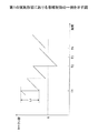
FIG. 6 shows an example of bandwidth control in the first embodiment. In the first embodiment, when a frame is read from the
<第2の実施形態>
帯域制御装置の構成は、第1および第2の実施形態において実質的に同じである。すなわち、第2の実施形態の帯域制御は、図4に示す帯域制御装置100により提供される。ただし、トークンバケツ103を制御する方法は、第1および第2の実施形態において異なる。
<Second Embodiment>
The configuration of the bandwidth control device is substantially the same in the first and second embodiments. That is, the bandwidth control of the second embodiment is provided by the
図7は、第2の実施形態の帯域制御方法を示すフローチャートである。このフローチャートの処理は、第1の実施形態と同様に、例えば、定期的に実行される。また、第1の実施形態と同様に、トークンバケツ103は、トークン制御部104により所定のレートでインクリメントされる。さらに、受信フレームは順番にフレームバッファ101に格納される。
FIG. 7 is a flowchart illustrating the bandwidth control method according to the second embodiment. The process of this flowchart is executed periodically, for example, as in the first embodiment. As in the first embodiment, the
第1の実施形態では、図5に示すように、フレームバッファ101から読み出された出力フレームの長さにかかわらず、実フレーム長を表す値だけトークンバケツ103がデクリメントされる。これに対して第2の実施形態では、図7に示すように、フレームバッファ101から読み出された出力フレームの長さが基準フレーム長よりも短いときは、S11において、トークン制御部104は、基準フレーム長を表す値だけトークンバケツ103をデクリメントする。また、フレームバッファ101から読み出された出力フレームの長さが基準フレーム長以上であるときは、S12において、トークン制御部104は、出力フレームの実フレーム長を表す値だけトークンバケツ103をデクリメントする。
In the first embodiment, as shown in FIG. 5, the
図8は、第2の実施形態における帯域制御の一例を示す。なお、図6および図8において、動作条件(トークン供給レート、基準フレーム長など)は同じである。 FIG. 8 shows an example of bandwidth control in the second embodiment. 6 and 8, the operating conditions (token supply rate, reference frame length, etc.) are the same.
時刻T4においてフレームバッファ101から読み出されるフレームの長さL2は、基準フレーム長よりも短い。この場合、第1の実施形態では、図6に示すように、トークン制御部104は、実フレーム長を表す値だけトークンバケツ103をデクリメントする。これに対して第2の実施形態では、図8に示すように、トークン制御部104は、基準フレーム長を表す値だけトークンバケツ103をデクリメントする。
The length L2 of the frame read from the
このように、第2の実施形態では、出力フレームの長さが基準フレーム長よりも短いときは、基準フレーム長を表す値だけトークンバケツ103がデクリメントされる。すなわち、第2の実施形態では、あるユーザのフレームの末尾に無効区間(または、ダミーデータ)が付加されたときは、その無効区間に対応する帯域は、そのユーザによって使用されたものとして帯域制御が実行される。このため、第1の実施形態と比較して、第2の実施形態では、トークンバケツ103の値が小さくなりやすい。
Thus, in the second embodiment, when the length of the output frame is shorter than the reference frame length, the
例えば、第1の実施形態では、図6に示すように、時刻T4においてトークンバケツ103の値は負になっていない。一方、第2の実施形態では、図8に示すように、時刻T4においてトークンバケツ103の値が負になっている。ここで、トークンバケツ103の値がゼロ以下である期間は、バッファ制御部102はフレームバッファ101からフレームを読み出すことはできない。よって、第2の実施形態では、トークンバケツ103を利用して、単位時間あたりの送信フレーム数を抑制することが可能である。したがって、第2の実施形態では、出力フレームの長さが基準フレーム長よりも短いときに、必ずしもその出力フレームの末尾に無効区間を付加しなくてもてもよい。この場合、帯域制御装置100は、フレーム長補正部106を有していなくてもよい。
For example, in the first embodiment, as shown in FIG. 6, the value of the
<第3の実施形態>
図9は、第3の実施形態に係わる帯域制御装置の構成を示す。第3の実施形態の帯域制御装置300は、図9に示すように、フレームバッファ101、トークンバケツ103、基準フレーム長テーブル105、フレーム長補正部106、キャッシュバケツ301、トークン制御部302、バッファ制御部303を有する。なお、フレームバッファ101、トークンバケツ103、基準フレーム長テーブル105、フレーム長補正部106は、第1および第3の実施形態において実質的に同じである。また、帯域制御装置300は、図9に示していない他の要素を有していてもよい。
<Third Embodiment>
FIG. 9 shows the configuration of the bandwidth control apparatus according to the third embodiment. As shown in FIG. 9, the
キャッシュバケツ301は、所定の条件の下でトークンバケツ103から取り出されたトークンを一時的に格納することができる。なお、この実施例では、トークンバケツ103と同様に、キャッシュバケツ301もトークンの個数をカウントする。よって、以下では、キャッシュバケツ301に格納されているトークンの個数を「キャッシュバケツ301の値」と呼ぶことがある。また、トークンバケツ103と同様に、キャッシュバケツ301もカウンタにより実現される。ただし、トークンバケツ103は指定されたレートでトークンが供給されるが、キャッシュバケツ301に対してそのようなトークンの供給は行われない。
The
トークン制御部302は、第1または第2の実施形態と同様の方法でトークンバケツ103を制御する。これに加えて、トークン制御部302は、キャッシュバケツ301も制御する。そして、バッファ制御部303は、トークンバケツ103の値だけでなく、キャッシュバケツ301の値も考慮して、フレームバッファ101からフレームを読み出して出力する。以下、フローチャートを参照しながら第3の実施形態の帯域制御装置300の動作を説明する。
The
図10は、第3の実施形態の帯域制御方法を示すフローチャートである。このフローチャートの処理は、第1の実施形態と同様に、例えば、定期的に実行される。また、第1の実施形態と同様に、トークンバケツ103は、トークン制御部302により所定のレートでインクリメントされる。さらに、受信フレームは順番にフレームバッファ101に格納される。
FIG. 10 is a flowchart illustrating the bandwidth control method according to the third embodiment. The process of this flowchart is executed periodically, for example, as in the first embodiment. As in the first embodiment, the
S1〜S5、S11、S12の処理は、第2及び第3の実施形態において同じである。すなわち、第3の実施形態においても、フレームバッファ101から読み出される出力フレームの長さが基準フレーム長よりも短いときは、出力フレームの末尾に無効区間(または、ダミーデータ)が付加され、基準フレーム長を表す値だけトークンバケツ103がデクリメントされる。また、出力フレームの長さが基準フレーム長以上であるときは、出力フレームに無効区間が付加されることはなく、実フレーム長を表す値だけトークンバケツ103がデクリメントされる。
The processes of S1 to S5, S11, and S12 are the same in the second and third embodiments. That is, also in the third embodiment, when the length of the output frame read from the
但し、第3の実施形態では、出力フレームの長さが基準フレーム長よりも短いときは、S11の後に、S21において、実フレーム長と基準フレーム長との差分に対応する個数のトークンがキャッシュバケツ301に格納される。すなわち、実フレーム長と基準フレーム長との差分を表す値だけキャッシュバケツ301がインクリメントされる。
However, in the third embodiment, when the length of the output frame is shorter than the reference frame length, after S11, in S21, the number of tokens corresponding to the difference between the actual frame length and the reference frame length is the cache bucket. 301. That is, the
また、第1および第2の実施形態では、トークンバケツ103にトークンが残っていないとき(すなわち、トークンバケツ103の値がゼロ以下であるとき)は、バッファ制御部102はフレームバッファ101からフレームを読み出すことはない。これに対して第3の実施形態では、トークンバケツ103にトークンが残っていないときであっても、S22〜S23の条件が満たされるときは、バッファ制御部102はフレームバッファ101からフレームを読み出すことができる。よって、トークンバケツ103にトークンが残っていないときは(S1:No)、帯域制御装置300の処理はS22へ移動する。
In the first and second embodiments, when no token remains in the token bucket 103 (that is, when the value of the
S22において、バッファ制御部303は、フレームバッファ101の先頭に格納されているフレームの長さ(以下、次フレーム長)が基準フレーム長であるか否か判定する。そして、次フレーム長が基準フレーム長以上であれば、バッファ制御部303の処理はS23へ進む。一方、次フレーム長が基準フレーム長よりも短いときは、バッファ制御部303の処理はS1へ戻る。
In S22, the
S23において、バッファ制御部303は、キャッシュバケツ301に残っているトークンの個数に対応するフレーム長(以下、キャッシュフレーム長)と次フレーム長とを比較する。そして、キャッシュフレーム長が次フレーム長以上であるときは、バッファ制御部303の処理はS24へ進む。すなわち、フレームバッファ101の先頭に格納されているフレームの長さに対して、キャッシュバケツ301に十分な数のトークンが格納されているときは、S24〜S25の処理が実行される。なお、キャッシュフレーム長が次フレーム長よりも短いときは、バッファ制御部303の処理はS1へ戻る。すなわち、フレームバッファ101の先頭に格納されているフレームの長さに対して、キャッシュバケツ301に十分な数のトークンが格納されていないときは、バッファ制御部303はフレームバッファ101からフレームを読み出さない。
In S23, the
S24において、バッファ制御部303は、フレームバッファ101の先頭に格納されているフレームを読み出して出力する。このとき、バッファ制御部303は、このフレームの末尾に無効区間を付加する必要はない。そして、S25において、トークン制御部302は、実フレーム長(すなわち、フレームバッファ101から読み出されたフレームの長さ)を表す値だけキャッシュバケツ301をデクリメントする。なお、S25の実フレーム長は、S22およびS23の次フレーム長と同じである。
In S24, the
このように、第3の実施形態では、出力フレームの長さが基準フレーム長よりも短いときは、基準フレーム長を表す値だけトークンバケツ103がデクリメントされる。すなわち、出力フレームの長さが基準フレーム長よりも短いときは、トークンバケツ103は、実フレーム長よりも長い基準フレーム長を表す値だけデクリメントされる。そして、この場合、トークン制御部302は、実フレーム長と基準フレーム長との差分を表す値だけキャッシュバケツ301をインクリメントする。
Thus, in the third embodiment, when the length of the output frame is shorter than the reference frame length, the
また、トークンバケツ103にトークンが残っていないときであっても、バッファ制御部303は、所定の条件の下でフレームバッファ101からフレームを読み出すことができる。具体的には、トークンバケツ103の値がゼロ以下であっても、下記の2つの条件が満たされているときは、バッファ制御部303はフレームバッファ101からフレームを読み出す。
(1)フレームバッファ101の先頭に格納されているフレームの長さ(即ち、次フレーム長)が基準フレーム長以上である。
(2)キャッシュバケツ301に残っているトークンの個数に対応するフレーム長が次フレーム長以上である。
Even when no token remains in the
(1) The length of the frame stored at the head of the frame buffer 101 (that is, the next frame length) is greater than or equal to the reference frame length.
(2) The frame length corresponding to the number of tokens remaining in the
ここで、第1〜第2の実施形態と第3の実施形態とを比較する。第1の実施形態では、実フレーム長が基準フレーム長より短いときであっても、トークンバケツ103は実フレーム長を表す値だけデクリメントされる。また、第2の実施形態では、実フレーム長が基準フレーム長よりも短いときは、トークンバケツ103は基準フレーム長を表す値だけデクリメントされる。すなわち、第1の実施形態と比較すると、第2の実施形態では、トークンバケツ103が「より大きく」デクリメントされる。
Here, the first to second embodiments are compared with the third embodiment. In the first embodiment, even when the actual frame length is shorter than the reference frame length, the
第3の実施形態では、第1の実施形態と第2の実施形態との間の「差分」がキャッシュバケツ301に格納される。すなわち、実フレーム長と基準フレーム長との差分を表す値だけキャッシュバケツ301がインクリメントされる。そして、キャッシュバケツ301に格納されたトークンは、上述の条件(1)及び(2)が満たされるときに使用される。すなわち、第3の実施形態の帯域制御は、無効区間を消費帯域として処理するか否かという観点において、第1の実施形態と第2の実施形態との中間に位置する。
In the third embodiment, “difference” between the first embodiment and the second embodiment is stored in the
また、第2の実施形態では、あるユーザの短フレームに対して無効区間が設けられたときに、その無効区間は、そのユーザの消費帯域としてカウントされる。このため、第2の実施形態では、短フレームが多いトラヒックに対しては、許容帯域に対して実際の送信データレートが十分に得られないおそれがある。これに対して第3の実施形態では、あるユーザの短フレームに対して無効区間が設けられたときに、その無効区間に相当するトークンがキャッシュバケツ301に格納される。そして、キャッシュバケツ301に格納されたトークンは、このユーザの他のフレームを送信するために使用される。すなわち、短フレームを送信する際に余分にカウントされた帯域が、他のフレームを送信するために利用される。したがって、第3の実施形態の帯域制御方法によれば、トークンバケツ103を利用して指定した送信データレートを保証することができる。
In the second embodiment, when an invalid section is provided for a short frame of a certain user, the invalid section is counted as the user's consumed bandwidth. For this reason, in the second embodiment, the actual transmission data rate may not be sufficiently obtained with respect to the allowable band for traffic with many short frames. In contrast, in the third embodiment, when an invalid section is provided for a short frame of a certain user, a token corresponding to the invalid section is stored in the
なお、バッファ制御部303およびトークン制御部302は、例えば、図10に示すフローチャートの処理を行うハードウェア回路により実現される。或いは、バッファ制御部303およびトークン制御部302は、図10に示すフローチャートの処理を記述したプログラムをプロセッサで実行することにより実現してもよい。さらに、バッファ制御部303およびトークン制御部302は、ハードウェア回路およびソフトウェアの組合せで実現してもよい。
The
図11は、第3の実施形態における帯域制御の一例を示す。この例では、時刻T11においてフレームバッファ101から読み出される出力フレームの長さL3は、基準フレーム長よりも短い。この場合、トークンバケツ103は、基準フレーム長を表す値だけデクリメントされる。このとき、トークンバケツ103から「余分に」取り出されたトークンがキャッシュバケツ301に格納される。すなわち、キャッシュバケツ301は、基準フレーム長と長さL3との差分(図11では、ΔL)だけインクリメントされる。同様に、時刻T12においても、キャッシュバケツ301はインクリメントされている。
FIG. 11 shows an example of bandwidth control in the third embodiment. In this example, the length L3 of the output frame read from the
時刻T13においてフレームバッファ101から読み出される出力フレームの長さは、基準フレーム長よりも長い。この場合、トークンバケツ103は、実フレーム長を表す値だけデクリメントされる。一方、キャッシュバケツ301の値は、そのまま維持される。同様に、時刻T14においても、トークンバケツ103は、実フレーム長を表す値だけデクリメントされる。
The length of the output frame read from the
時刻T15においては、トークンバケツ103の値は負である。ここで、時刻T15においてフレームバッファ101の先頭に格納されているフレームの長さ(即ち、次フレーム長)が基準フレーム長以上であるものとする。また、キャッシュバケツ301に格納されているトークンの個数が基準フレーム長に対応するトークン数以上である。よって、この場合、バッファ制御部303は、フレームバッファ101の先頭に格納されているフレームを読み出して出力することができる。このとき、トークン制御部302は、実フレーム長(ここでは、次フレーム長)を表す値だけキャッシュバケツ301をデクリメントする。ただし、トークンバケツ103の値は、そのまま維持される。
At time T15, the value of the
<第4の実施形態>
第4の実施形態では、クラス毎に基準フレーム長が設定され、クラス毎に送信データレートおよび送信フレーム数の双方が制御される。
<Fourth Embodiment>
In the fourth embodiment, a reference frame length is set for each class, and both the transmission data rate and the number of transmission frames are controlled for each class.
図12は、第4の実施形態に係わる帯域制御装置の構成を示す。第4の実施形態の帯域制御装置400は、図12に示すように、フレームバッファ401、トークンバケツ103、基準フレーム長テーブル402−1〜402−n、フレーム長補正部106、キャッシュバケツ301、トークン制御部302、バッファ制御部303を有する。なお、トークンバケツ103、フレーム長補正部106、キャッシュバケツ301、トークン制御部302、バッファ制御部303は、第3および第4の実施形態において実質的に同じである。また、帯域制御装置400は、図12に示していない他の要素を有していてもよい。
FIG. 12 shows the configuration of the bandwidth control apparatus according to the fourth embodiment. As shown in FIG. 12, the
フレームバッファ401は、受信フレームをクラス毎に格納する。クラスは、この例では、VLANタグ内の優先度(Priority)ビットで識別される。即ち、フレームバッファ401は、各フレームの優先度ごとに受信フレームを格納することができる。また、基準フレーム長テーブル402−1〜402−nには、それぞれ、各クラスに対して指定された基準フレーム長が登録されている。即ち、第4の実施形態では、VLANタグで指定される各ユーザの優先度に対して基準フレーム長が設定される。
The
1つの実施例としては、優先度の高いVLANユーザに対して使用される基準フレーム長は短い。そうすると、このユーザのフレームに対して無効区間が付加されにくくなる。よって、優先度の高いVLANユーザの送信フレーム数は、抑制されにくくなる。一方、優先度の低いVLANユーザに対して使用される基準フレーム長は長い。そうすると、このユーザのフレームに対して無効区間が付加されやすくなる。したがって、優先度の低いVLANユーザの送信フレーム数は抑制されやすくなる。このような構成とすれば、優先度の低いフレームのバーストが抑制され、優先度の高いユーザのトラヒックがバースト性を有していても、コンピュータ資源(例えば、フレーム処理部110)はそのユーザのフレームを処理することができる。 In one embodiment, the reference frame length used for high priority VLAN users is short. Then, it becomes difficult to add an invalid section to this user's frame. Therefore, the number of transmission frames of VLAN users with high priority is difficult to be suppressed. On the other hand, the reference frame length used for VLAN users with low priority is long. Then, an invalid section is easily added to the user's frame. Therefore, the number of transmission frames of VLAN users with low priority is easily suppressed. With such a configuration, bursts of low priority frames are suppressed, and even if high priority user traffic is bursty, the computer resources (for example, the frame processing unit 110) are able to The frame can be processed.
なお、フレーム処理部110で実行される処理ステップの数は、ネットワークアプリケーションまたはサービスアプリケーションに依存する。したがって、クラス毎に基準フレーム長を設定するかわりに、アプリケーション毎に基準フレーム長を設定してもよい。例えば、フレーム処理部110で実行される処理ステップの数が多いアプリケーションに対して長い基準フレーム長が与えられる。このような設定とすれば、フレーム処理部110の負荷が効率的に削減され、伝送装置の処理能力が向上する。
Note that the number of processing steps executed by the
このように、第4の実施形態によれば、全体として送信データレートを制御しながら、任意のグループ(優先度、アプリケーションなど)毎に送信フレーム数の制御を行うことができる。なお、図12に示す帯域制御装置は、図9に示す構成をベースにしているが、第4の実施形態の帯域制御は、図4に示す構成をベースにして実現してもよい。 As described above, according to the fourth embodiment, the number of transmission frames can be controlled for each arbitrary group (priority, application, etc.) while controlling the transmission data rate as a whole. The band control device shown in FIG. 12 is based on the configuration shown in FIG. 9, but the band control of the fourth embodiment may be realized based on the configuration shown in FIG.
<他の実施形態>
上述した第1〜第4の実施形態の帯域制御装置は、トークンバケツ103を利用して送信データレートおよび送信フレーム数を制御する。これに対して図13に示す帯域制御装置500は、量的トークンバケツ501および量的トークン制御部502を利用して送信データレートを制御し、数的トークンバケツ503および数的トークン制御部504を利用して送信フレーム数を制御する。なお、量的トークンバケツ501および量的トークン制御部502は、例えば、第1の実施形態のトークンバケツ103およびトークン制御部104と同様に動作する。また、数的トークンバケツ503は、所定のレートでインクリメントされ、フレームバッファ101からフレームが読み出されたときに1だけデクリメントされる。
<Other embodiments>
The band control devices according to the first to fourth embodiments described above control the transmission data rate and the number of transmission frames using the
ただし、図13に示す帯域制御装置500においては、各ユーザに対して量的トークンバケツ501、量的トークン制御部502、数的トークンバケツ503、数的トークン制御部504を設ける必要がある。これに対して、図4に示す帯域制御装置100は、送信フレーム数を制御するための回路(図13では、数的トークンバケツ503および数的トークン制御部504)を設けることなく、送信フレーム数を制御することができる。よって、図13に示す構成と比較して、図4に示す構成によれば、回路規模が小さくなり、伝送装置のコストを削減することができる。
However, in the
図9に示す帯域制御装置300は、図4に示す構成に加えて、キャッシュバケツ301を有する。ただし、キャッシュバケツ301は、トークンバケツ103によって余計にカウントされたトークンを一時的に格納するために設けられている。このため、図13に示す量的トークンバケツ501または数的トークンバケツ503と比較して、キャッシュバケツ301の回路規模を小さくするこが可能である。これに加えて、キャッシュバケツ301には、所定のレートでトークンを供給する処理は行われない。よって、図13に示す構成と比較して、図4に示す構成によっても、回路規模が小さくなり、伝送装置のコストを削減することができる。
A
以上記載した各実施例を含む実施形態に関し、さらに以下の付記を開示する。
(付記1)
第1のカウンタと、
指定されたレートで前記第1のカウンタをインクリメントするカウンタ制御部と、
受信フレームを格納するフレームバッファと、
前記第1のカウンタの値が所定の閾値よりも大きいときに、前記フレームバッファからフレームを読み出して出力するバッファ制御部と、を有し、
前記バッファ制御部により前記フレームバッファから読み出された出力フレームの長さが指定された基準フレーム長よりも短いときは、前記カウンタ制御部は、前記基準フレーム長を表す値だけ前記第1のカウンタをデクリメントし、
前記出力フレームの長さが前記基準フレーム長以上であるときは、前記カウンタ制御部は、前記出力フレームの長さを表す値だけ前記第1のカウンタをデクリメントする
ことを特徴とする伝送装置。
(付記2)
前記出力フレームの長さが前記基準フレーム長よりも短いときは、前記バッファ制御部は、前記出力フレームに対して割り当てられる区間の後に、前記出力フレームの長さと前記基準フレーム長との差分に対応する時間だけ、前記フレームバッファから次のフレームを読み出す処理を禁止する無効区間を設ける
ことを特徴とする付記1に記載の伝送装置。
(付記3)
前記出力フレームの長さが前記基準フレーム長よりも短いときに、前記出力フレームの長さが前記基準フレーム長になるように前記出力フレームを補正するフレーム長補正部をさらに有する
ことを特徴とする付記1に記載の伝送装置。
(付記4)
第2のカウンタをさらに有し、
前記出力フレームの長さが前記基準フレーム長よりも短いときは、前記カウンタ制御部は、前記出力フレームの長さと前記基準フレーム長との差分を表す値だけ前記第2のカウンタをインクリメントし、
前記第1のカウンタの値が前記閾値以下であり、且つ、前記フレームバッファの先頭に格納されている先頭フレームの長さが前記基準フレーム長以上であり、且つ、前記第2のカウンタの値が前記先頭フレームの長さを表す値以上であるときは、
前記バッファ制御部は、前記フレームバッファから前記先頭フレームを読み出して出力し、
前記カウンタ制御部は、前記先頭フレームの長さを表す値だけ前記第2のカウンタをデクリメントする
ことを特徴とする付記1に記載の伝送装置。
(付記5)
前記フレームバッファは、送信元ユーザ毎に受信フレームを格納する構成であり、
前記基準フレーム長は、前記ユーザ毎に指定される
ことを特徴とする付記1〜4のいずれか1つに記載の伝送装置。
(付記6)
前記フレームバッファは、各フレームの優先度ごとに受信フレームを格納する構成であり、
前記基準フレーム長は、前記優先度に応じて指定される
ことを特徴とする付記1〜4のいずれか1つに記載の伝送装置。
(付記7)
前記優先度が高いほど長い基準フレーム長が指定される
ことを特徴とする付記6に記載の伝送装置。
(付記8)
前記フレームバッファは、各フレームに格納されているデータに関連するアプリケーション毎に受信フレームを格納する構成であり、
前記基準フレーム長は、前記アプリケーション毎に指定される
ことを特徴とする付記1〜4のいずれか1つに記載の伝送装置。
(付記9)
カウンタと、
指定されたレートで前記カウンタをインクリメントするカウンタ制御部と、
受信フレームを格納するフレームバッファと、
前記カウンタの値が所定の閾値よりも大きいときに、前記フレームバッファからフレームを読み出して出力するバッファ制御部と、を有し、
前記カウンタ制御部は、前記バッファ制御部により前記フレームバッファから読み出された出力フレームの長さに基づいて決まる値だけ前記カウンタをデクリメントし、
前記出力フレームの長さが前記基準フレーム長よりも短いときは、前記バッファ制御部は、前記出力フレームに対して割り当てられる区間の後に、前記出力フレームの長さと前記基準フレーム長との差分に対応する時間だけ、前記フレームバッファから次のフレームを読み出す処理を禁止する無効区間を設ける
ことを特徴とする伝送装置。
(付記10)
受信フレームを格納するフレームバッファを有する伝送装置においてフレームの送信を制御する伝送方法であって、
指定されたレートでカウンタをインクリメントし、
前記カウンタの値が所定の閾値よりも大きいときに、前記フレームバッファからフレームを読み出して出力し、
前記フレームバッファから読み出された出力フレームの長さが指定された基準フレーム長よりも短いときに、前記基準フレーム長を表す値だけ前記カウンタをデクリメントし、
前記出力フレームの長さが前記基準フレーム長以上であるときに、前記出力フレームの長さを表す値だけ前記カウンタをデクリメントする
ことを特徴とする伝送方法。
The following additional notes are further disclosed with respect to the embodiments including the examples described above.
(Appendix 1)
A first counter;
A counter controller for incrementing the first counter at a specified rate;
A frame buffer for storing received frames;
A buffer control unit that reads out and outputs a frame from the frame buffer when the value of the first counter is greater than a predetermined threshold;
When the length of the output frame read from the frame buffer by the buffer control unit is shorter than the specified reference frame length, the counter control unit sets the first counter by a value representing the reference frame length. Decrement
When the length of the output frame is equal to or longer than the reference frame length, the counter control unit decrements the first counter by a value representing the length of the output frame.
(Appendix 2)
When the length of the output frame is shorter than the reference frame length, the buffer control unit corresponds to the difference between the length of the output frame and the reference frame length after a section allocated to the output frame. The transmission apparatus according to
(Appendix 3)
A frame length correction unit configured to correct the output frame so that the length of the output frame becomes the reference frame length when the length of the output frame is shorter than the reference frame length; The transmission apparatus according to
(Appendix 4)
A second counter;
When the length of the output frame is shorter than the reference frame length, the counter control unit increments the second counter by a value representing a difference between the length of the output frame and the reference frame length,
The value of the first counter is less than or equal to the threshold, the length of the head frame stored at the head of the frame buffer is greater than or equal to the reference frame length, and the value of the second counter is When it is greater than or equal to the value representing the length of the first frame,
The buffer control unit reads and outputs the first frame from the frame buffer,
The transmission apparatus according to
(Appendix 5)
The frame buffer is configured to store a received frame for each transmission source user,
The transmission apparatus according to any one of
(Appendix 6)
The frame buffer is configured to store a received frame for each frame priority,
The transmission apparatus according to any one of
(Appendix 7)
The transmission apparatus according to
(Appendix 8)
The frame buffer is configured to store a received frame for each application related to data stored in each frame,
The transmission apparatus according to any one of
(Appendix 9)
A counter,
A counter controller for incrementing the counter at a specified rate;
A frame buffer for storing received frames;
A buffer control unit that reads out and outputs a frame from the frame buffer when the value of the counter is greater than a predetermined threshold;
The counter controller decrements the counter by a value determined based on the length of the output frame read from the frame buffer by the buffer controller;
When the length of the output frame is shorter than the reference frame length, the buffer control unit corresponds to the difference between the length of the output frame and the reference frame length after a section allocated to the output frame. A transmission apparatus is provided, wherein an invalid section is provided that prohibits a process of reading a next frame from the frame buffer for a predetermined time.
(Appendix 10)
A transmission method for controlling transmission of a frame in a transmission apparatus having a frame buffer for storing a received frame,
Increment the counter at the specified rate,
When the value of the counter is greater than a predetermined threshold, the frame is read out from the frame buffer and output,
When the length of the output frame read from the frame buffer is shorter than a specified reference frame length, the counter is decremented by a value representing the reference frame length;
When the length of the output frame is equal to or longer than the reference frame length, the counter is decremented by a value representing the length of the output frame.
1 伝送装置
100、300、400 帯域制御装置
101、401 フレームバッファ
102、303 バッファ制御部
103 トークンバケツ
104、302 トークン制御部
105 基準フレーム長テーブル
106 フレーム長補正部
301 キャッシュバケツ
402−1〜402−n 基準フレーム長テーブル
1
Claims (7)
指定されたレートで前記第1のカウンタをインクリメントするカウンタ制御部と、
受信フレームを格納するフレームバッファと、
前記第1のカウンタの値が所定の閾値よりも大きいときに、前記フレームバッファからフレームを読み出して出力するバッファ制御部と、を有し、
前記バッファ制御部により前記フレームバッファから読み出された出力フレームの長さが指定された基準フレーム長よりも短いときは、前記カウンタ制御部は、前記基準フレーム長を表す値だけ前記第1のカウンタをデクリメントし、
前記出力フレームの長さが前記基準フレーム長以上であるときは、前記カウンタ制御部は、前記出力フレームの長さを表す値だけ前記第1のカウンタをデクリメントする
ことを特徴とする伝送装置。 A first counter;
A counter controller for incrementing the first counter at a specified rate;
A frame buffer for storing received frames;
A buffer control unit that reads out and outputs a frame from the frame buffer when the value of the first counter is greater than a predetermined threshold;
When the length of the output frame read from the frame buffer by the buffer control unit is shorter than the specified reference frame length, the counter control unit sets the first counter by a value representing the reference frame length. Decrement
When the length of the output frame is equal to or longer than the reference frame length, the counter control unit decrements the first counter by a value representing the length of the output frame.
ことを特徴とする請求項1に記載の伝送装置。 When the length of the output frame is shorter than the reference frame length, the buffer control unit corresponds to the difference between the length of the output frame and the reference frame length after a section allocated to the output frame. The transmission apparatus according to claim 1, further comprising: an invalid section that prohibits a process of reading a next frame from the frame buffer for a period of time.
ことを特徴とする請求項1に記載の伝送装置。 A frame length correction unit configured to correct the output frame so that the length of the output frame becomes the reference frame length when the length of the output frame is shorter than the reference frame length; The transmission apparatus according to claim 1.
前記出力フレームの長さが前記基準フレーム長よりも短いときは、前記カウンタ制御部は、前記出力フレームの長さと前記基準フレーム長との差分を表す値だけ前記第2のカウンタをインクリメントし、
前記第1のカウンタの値が前記閾値以下であり、且つ、前記フレームバッファの先頭に格納されている先頭フレームの長さが前記基準フレーム長以上であり、且つ、前記第2のカウンタの値が前記先頭フレームの長さを表す値以上であるときは、
前記バッファ制御部は、前記フレームバッファから前記先頭フレームを読み出して出力し、
前記カウンタ制御部は、前記先頭フレームの長さを表す値だけ前記第2のカウンタをデクリメントする
ことを特徴とする請求項1に記載の伝送装置。 A second counter;
When the length of the output frame is shorter than the reference frame length, the counter control unit increments the second counter by a value representing a difference between the length of the output frame and the reference frame length,
The value of the first counter is less than or equal to the threshold, the length of the head frame stored at the head of the frame buffer is greater than or equal to the reference frame length, and the value of the second counter is When it is greater than or equal to the value representing the length of the first frame,
The buffer control unit reads and outputs the first frame from the frame buffer,
The transmission apparatus according to claim 1, wherein the counter control unit decrements the second counter by a value representing a length of the head frame.
前記基準フレーム長は、前記優先度に応じて指定される
ことを特徴とする請求項1〜4のいずれか1つに記載の伝送装置。 The frame buffer is configured to store a received frame for each frame priority,
The transmission apparatus according to any one of claims 1 to 4, wherein the reference frame length is designated according to the priority.
指定されたレートで前記カウンタをインクリメントするカウンタ制御部と、
受信フレームを格納するフレームバッファと、
前記カウンタの値が所定の閾値よりも大きいときに、前記フレームバッファからフレームを読み出して出力するバッファ制御部と、を有し、
前記カウンタ制御部は、前記バッファ制御部により前記フレームバッファから読み出された出力フレームの長さに基づいて決まる値だけ前記カウンタをデクリメントし、
前記出力フレームの長さが指定された基準フレーム長よりも短いときは、前記バッファ制御部は、前記出力フレームに対して割り当てられる区間の後に、前記出力フレームの長さと前記基準フレーム長との差分に対応する時間だけ、前記フレームバッファから次のフレームを読み出す処理を禁止する無効区間を設ける
ことを特徴とする伝送装置。 A counter,
A counter controller for incrementing the counter at a specified rate;
A frame buffer for storing received frames;
A buffer control unit that reads out and outputs a frame from the frame buffer when the value of the counter is greater than a predetermined threshold;
The counter controller decrements the counter by a value determined based on the length of the output frame read from the frame buffer by the buffer controller;
When the length of the output frame is shorter than the designated reference frame length, the buffer control unit, after the section allocated to the output frame, the difference between the length of the output frame and the reference frame length A transmission apparatus is provided, wherein an invalid section is provided that prohibits a process of reading a next frame from the frame buffer for a time corresponding to.
指定されたレートでカウンタをインクリメントし、
前記カウンタの値が所定の閾値よりも大きいときに、前記フレームバッファからフレームを読み出して出力し、
前記フレームバッファから読み出された出力フレームの長さが指定された基準フレーム長よりも短いときに、前記基準フレーム長を表す値だけ前記カウンタをデクリメントし、
前記出力フレームの長さが前記基準フレーム長以上であるときに、前記出力フレームの長さを表す値だけ前記カウンタをデクリメントする
ことを特徴とする伝送方法。 A transmission method for controlling transmission of a frame in a transmission apparatus having a frame buffer for storing a received frame,
Increment the counter at the specified rate,
When the value of the counter is greater than a predetermined threshold, the frame is read out from the frame buffer and output,
When the length of the output frame read from the frame buffer is shorter than a specified reference frame length, the counter is decremented by a value representing the reference frame length;
When the length of the output frame is equal to or longer than the reference frame length, the counter is decremented by a value representing the length of the output frame.
Priority Applications (2)
| Application Number | Priority Date | Filing Date | Title |
|---|---|---|---|
| JP2014049836A JP6281338B2 (en) | 2014-03-13 | 2014-03-13 | Transmission apparatus and transmission method |
| US14/612,720 US9749265B2 (en) | 2014-03-13 | 2015-02-03 | Transmission device and transmission method |
Applications Claiming Priority (1)
| Application Number | Priority Date | Filing Date | Title |
|---|---|---|---|
| JP2014049836A JP6281338B2 (en) | 2014-03-13 | 2014-03-13 | Transmission apparatus and transmission method |
Publications (2)
| Publication Number | Publication Date |
|---|---|
| JP2015177215A JP2015177215A (en) | 2015-10-05 |
| JP6281338B2 true JP6281338B2 (en) | 2018-02-21 |
Family
ID=54070229
Family Applications (1)
| Application Number | Title | Priority Date | Filing Date |
|---|---|---|---|
| JP2014049836A Expired - Fee Related JP6281338B2 (en) | 2014-03-13 | 2014-03-13 | Transmission apparatus and transmission method |
Country Status (2)
| Country | Link |
|---|---|
| US (1) | US9749265B2 (en) |
| JP (1) | JP6281338B2 (en) |
Family Cites Families (9)
| Publication number | Priority date | Publication date | Assignee | Title |
|---|---|---|---|---|
| JP5048184B2 (en) * | 2001-01-26 | 2012-10-17 | 富士通株式会社 | Transmission rate monitoring apparatus and transmission rate monitoring method |
| JP4163044B2 (en) * | 2003-05-09 | 2008-10-08 | 古河電気工業株式会社 | BAND CONTROL METHOD AND BAND CONTROL DEVICE THEREOF |
| JP4027955B2 (en) * | 2003-06-03 | 2007-12-26 | 富士通株式会社 | Flow control device |
| US7564790B2 (en) * | 2005-02-28 | 2009-07-21 | Cisco Technology, Inc. | Method and system for shaping traffic in a parallel queuing hierarchy |
| JP4519079B2 (en) * | 2006-01-31 | 2010-08-04 | 富士通株式会社 | Concentrator |
| JP2009010449A (en) | 2007-06-26 | 2009-01-15 | Panasonic Corp | Radio communications equipment and packet transmission method therefor |
| JP2009147569A (en) * | 2007-12-12 | 2009-07-02 | Fujitsu Ltd | Frame transmission device and frame reception device |
| JP2009200947A (en) * | 2008-02-22 | 2009-09-03 | Fujitsu Ltd | Packet transmitter, packet transmission method, and packet transmission program |
| JP5533303B2 (en) | 2010-06-11 | 2014-06-25 | 富士通株式会社 | Packet transmission device, packet transmission method, and packet transmission program |
-
2014
- 2014-03-13 JP JP2014049836A patent/JP6281338B2/en not_active Expired - Fee Related
-
2015
- 2015-02-03 US US14/612,720 patent/US9749265B2/en active Active
Also Published As
| Publication number | Publication date |
|---|---|
| JP2015177215A (en) | 2015-10-05 |
| US20150263969A1 (en) | 2015-09-17 |
| US9749265B2 (en) | 2017-08-29 |
Similar Documents
| Publication | Publication Date | Title |
|---|---|---|
| US7280478B2 (en) | Control packet structure and method for generating a data burst in optical burst switching networks | |
| CN108243120B (en) | Service flow transmission method, device and communication system based on flexible Ethernet | |
| US20210083970A1 (en) | Packet Processing Method and Apparatus | |
| US20090180478A1 (en) | Ethernet switching method and ethernet switch | |
| EP3605975B1 (en) | Client service transmission method and device | |
| JP7231749B2 (en) | Packet scheduling method, scheduler, network device and network system | |
| JP2007201965A (en) | Packet repeating apparatus having transmission control function | |
| JP6236945B2 (en) | Transmission apparatus, transmission system, and transmission method | |
| KR20130093702A (en) | Packet transport system and traffic management method thereof | |
| JP4648207B2 (en) | Transmission apparatus and line speed changing method | |
| JP2008118281A (en) | Communication device | |
| JP6236925B2 (en) | Transmission apparatus and transmission method | |
| JP4652314B2 (en) | Ether OAM switch device | |
| JP2020017903A (en) | Communication system, communication control method, and communication device | |
| US20150109922A1 (en) | Method and apparatus for bandwidth adjustment in network virtualization system | |
| US20060222007A1 (en) | RPR ring network system | |
| WO2022183879A1 (en) | Packet forwarding method, electronic device, and storage medium | |
| JP6281338B2 (en) | Transmission apparatus and transmission method | |
| CN115250389A (en) | Optical network terminal | |
| CN114124833A (en) | Method, network equipment and system for controlling message sending | |
| JP2017521961A (en) | Signaling for transmitting coherent data flows in packet-switched networks | |
| CN114070776B (en) | Improved time-sensitive network data transmission method, device and equipment | |
| US8976812B2 (en) | Communication apparatus and band control method | |
| JP4531660B2 (en) | Packet relay device | |
| JP2007335986A (en) | Communication device and communication method |
Legal Events
| Date | Code | Title | Description |
|---|---|---|---|
| A621 | Written request for application examination |
Free format text: JAPANESE INTERMEDIATE CODE: A621 Effective date: 20161102 |
|
| A977 | Report on retrieval |
Free format text: JAPANESE INTERMEDIATE CODE: A971007 Effective date: 20170816 |
|
| A131 | Notification of reasons for refusal |
Free format text: JAPANESE INTERMEDIATE CODE: A131 Effective date: 20170919 |
|
| A521 | Request for written amendment filed |
Free format text: JAPANESE INTERMEDIATE CODE: A523 Effective date: 20171012 |
|
| TRDD | Decision of grant or rejection written | ||
| A01 | Written decision to grant a patent or to grant a registration (utility model) |
Free format text: JAPANESE INTERMEDIATE CODE: A01 Effective date: 20171226 |
|
| A61 | First payment of annual fees (during grant procedure) |
Free format text: JAPANESE INTERMEDIATE CODE: A61 Effective date: 20180108 |
|
| R150 | Certificate of patent or registration of utility model |
Ref document number: 6281338 Country of ref document: JP Free format text: JAPANESE INTERMEDIATE CODE: R150 |
|
| LAPS | Cancellation because of no payment of annual fees |