JP6281179B2 - Game machine - Google Patents

Game machine Download PDF

Info

Publication number
JP6281179B2
JP6281179B2 JP2013017907A JP2013017907A JP6281179B2 JP 6281179 B2 JP6281179 B2 JP 6281179B2 JP 2013017907 A JP2013017907 A JP 2013017907A JP 2013017907 A JP2013017907 A JP 2013017907A JP 6281179 B2 JP6281179 B2 JP 6281179B2
Authority
JP
Japan
Prior art keywords
effect member
unit
gear
base
rack
Prior art date
Legal status (The legal status is an assumption and is not a legal conclusion. Google has not performed a legal analysis and makes no representation as to the accuracy of the status listed.)
Active
Application number
JP2013017907A
Other languages
Japanese (ja)
Other versions
JP2014140598A (en
Inventor
和則 久保
和則 久保
拓 清水
清水  拓
Current Assignee (The listed assignees may be inaccurate. Google has not performed a legal analysis and makes no representation or warranty as to the accuracy of the list.)
Sanyo Bussan Co Ltd
Original Assignee
Sanyo Bussan Co Ltd
Priority date (The priority date is an assumption and is not a legal conclusion. Google has not performed a legal analysis and makes no representation as to the accuracy of the date listed.)
Filing date
Publication date
Application filed by Sanyo Bussan Co Ltd filed Critical Sanyo Bussan Co Ltd
Priority to JP2013017907A priority Critical patent/JP6281179B2/en
Publication of JP2014140598A publication Critical patent/JP2014140598A/en
Application granted granted Critical
Publication of JP6281179B2 publication Critical patent/JP6281179B2/en
Active legal-status Critical Current
Anticipated expiration legal-status Critical

Links

Images

Description

本発明は、パチンコ機などの遊技機に関するものである。   The present invention relates to a gaming machine such as a pachinko machine.

パチンコ機等の遊技機において、ベース部材と、そのベース部材に基端側がスライド移動可能に支持される移動部材と、その移動部材をスライド移動させるための駆動力を発生する駆動手段とを備え、その駆動手段の駆動力により移動部材をベース部材に対してスライド移動させる遊技機がある。   In a gaming machine such as a pachinko machine, it comprises a base member, a moving member whose base end side is slidably supported by the base member, and a driving means for generating a driving force for sliding the moving member, There is a gaming machine in which a moving member is slid with respect to a base member by a driving force of the driving means.

特開2010−200914号公報JP 2010-200194 A

しかしながら、上述した従来の遊技機では、駆動手段から付与された駆動力によって移動部材のスライド移動が開始される際の初期動作をスムーズに行うことが困難であるという問題点があった。   However, the conventional gaming machine described above has a problem that it is difficult to smoothly perform the initial operation when the sliding movement of the moving member is started by the driving force applied from the driving unit.

本発明は、上記例示した問題点を解決するためになされたものであり、駆動手段から付与された駆動力によって移動部材のスライド移動が開始される際の初期動作をスムーズに行うことができる遊技機を提供することを目的とする。   The present invention has been made to solve the above-described problems, and a game that can smoothly perform an initial operation when a sliding movement of a moving member is started by a driving force applied from a driving unit. The purpose is to provide a machine.

この目的を達成するために請求項1記載の遊技機は、ベース部材と、そのベース部材にスライド移動可能に支持される移動部材と、その移動部材をスライド移動させるための駆動力を発生する駆動手段と、を備えたものであり、前記移動部材は、前記駆動手段から駆動力が付与される被駆動部材と、その被駆動部材に軸支により相対移動可能に連結されると共に前記ベース部材に案内されて移動する連結部材と、を備え、前記被駆動部材と前記連結部材とを軸支する軸および軸孔は、前記軸の外周面と前記軸孔の内周面との間に隙間を有し、前記被駆動部材と前記連結部材とは、前記軸に直交する平面内で相対的に水平移動可能とされ、前記被駆動部材および連結部材の一方は、前記被駆動部材および連結部材の他方に当接してその相対変位を規制する規制部を備える。
In order to achieve this object, a gaming machine according to claim 1 is a base member, a moving member that is slidably supported by the base member, and a drive that generates a driving force for sliding the moving member. The moving member is connected to a driven member to which a driving force is applied from the driving unit, and is connected to the driven member by a shaft support so as to be relatively movable and to the base member. A shaft and a shaft hole that pivotally supports the driven member and the connection member, and a gap is formed between the outer peripheral surface of the shaft and the inner peripheral surface of the shaft hole. The driven member and the connecting member are relatively horizontally movable within a plane orthogonal to the axis, and one of the driven member and the connecting member is a member of the driven member and the connecting member. Relative displacement against the other Ru equipped with a regulation portion for regulating.

請求項2記載の遊技機は、請求項1記載の遊技機において、発光する発光手段を備える。
Gaming machine of claim 2, in the gaming machine according to claim 1, wherein, Ru comprises a light emitting means for emitting light.

請求項1記載の遊技機によれば、初期動作をスムーズに行うことができる
According to claim 1 the gaming machine according, it is possible to perform the initial operation smoothly.

第1実施形態におけるパチンコ機の正面図である。It is a front view of the pachinko machine in a 1st embodiment. パチンコ機の遊技盤の正面図である。It is a front view of the game board of a pachinko machine. パチンコ機の背面図である。It is a rear view of a pachinko machine. パチンコ機の電気的構成を示すブロック図である。It is a block diagram which shows the electric constitution of a pachinko machine. 動作ユニットの正面斜視図である。It is a front perspective view of an operation unit. 動作ユニットの正面分解斜視図である。It is a front exploded perspective view of an operation unit. 第1ユニットの正面斜視図である。It is a front perspective view of a 1st unit. 第1ユニットの正面分解斜視図である。It is a front exploded perspective view of the 1st unit. 第1ベース体および第1カバー体の正面分解斜視図である。It is a front exploded perspective view of the 1st base body and the 1st cover body. (a)は、図9のXa−Xa線における第1ベース体の部分拡大断面図であり、(b)は、図9のXb−Xb線における第1カバー体の断面図である。(A) is the elements on larger scale of the 1st base body in the Xa-Xa line of FIG. 9, (b) is sectional drawing of the 1st cover body in the Xb-Xb line of FIG. 第1演出部材の正面分解斜視図である。It is a front exploded perspective view of the 1st production member. (a)は、第1演出部材の正面図であり、(b)は、図12(a)の矢印XIIb方向視における第1演出部材の側面図である。(A) is a front view of a 1st effect member, (b) is a side view of the 1st effect member in the arrow XIIb direction view of Fig.12 (a). (a)は、第1演出部材の背面図であり、(b)及び(c)は、図13(a)のXIIIb部における第1演出部材の部分拡大背面図である。(A) is a rear view of the first effect member, and (b) and (c) are partially enlarged rear views of the first effect member in the XIIIb portion of FIG. 13 (a). (a)は、第1演出部材が上昇位置に配置された状態における第1ユニットの正面図であり、(b)は、第1演出部材が下降位置に配置された状態における第1ユニットの正面図である。(A) is a front view of the 1st unit in the state where the 1st production member is arranged in the raise position, (b) is the front of the 1st unit in the state where the 1st production member is arranged in the down position FIG. 第2ユニットの正面斜視図である。It is a front perspective view of a 2nd unit. (a)は、第2カバー体の部分拡大正面図であり、(b)は、図16(a)のXVIb−XVIb線における第2カバー体の部分拡大断面図である。(A) is a partial enlarged front view of a 2nd cover body, (b) is a partial expanded sectional view of the 2nd cover body in the XVIb-XVIb line | wire of Fig.16 (a). (a)は、支持部材の正面図であり、(b)は、支持部材の背面図であり、(c)は、図17(a)のXVIIc−XVIIc線における支持部材の断面図である。(A) is a front view of a support member, (b) is a rear view of a support member, (c) is sectional drawing of the support member in the XVIIc-XVIIc line | wire of Fig.17 (a). 支持壁、背面規制および正面規制リブの位置関係を模式的に図示する模式図である。It is a schematic diagram which illustrates typically the positional relationship of a support wall, a back surface regulation, and a front surface regulation rib. (a)は、第1ユニット及び第2ユニットの正面図であり、(b)は、図19(a)のXIXb−XIXb線における第1ユニット及び第2ユニットの断面図である。(A) is a front view of a 1st unit and a 2nd unit, (b) is sectional drawing of the 1st unit and 2nd unit in the XIXb-XIXb line | wire of Fig.19 (a). 下方視における第1ユニット及び第2ユニットの模式図である。It is a schematic diagram of the 1st unit and 2nd unit in a downward view. 第3ユニットの正面分解斜視図である。It is a front exploded perspective view of the 3rd unit. 第3ユニットの背面分解斜視図である。It is a back surface exploded perspective view of the 3rd unit. 第4ユニットの正面斜視図である。It is a front perspective view of a 4th unit. 第4ケースの正面斜視図である。It is a front perspective view of a 4th case. 駆動部配設凹部を部分的に拡大した第4ケースの部分拡大正面図である。It is the partial enlarged front view of the 4th case which expanded the drive part arrangement | positioning recessed part partially. 駆動部配設凹部を部分的に拡大した第4ケースの部分拡大正面斜視図である。It is a partial expansion front perspective view of the 4th case which expanded a drive part arrangement crevice partially. 右ギヤ部材の背面斜視図である。It is a back perspective view of a right gear member. (a)は、右ギヤ部材の背面図であり、(b)は、図28(a)のXXVIIIb−XXVIIIb線における右ギヤ部材の断面図である。(A) is a rear view of a right gear member, (b) is sectional drawing of the right gear member in the XXVIIIb-XXVIIIb line | wire of Fig.28 (a). 第4内側リブ及び第4外側リブが形成される領域を部分的に拡大した第4ケースの部分拡大正面図である。It is the elements on larger scale of the 4th case which expanded the field where the 4th inner side rib and the 4th outside rib are formed partially. 第4演出部材の正面斜視図である。It is a front perspective view of the 4th production member. (a)は、左演出部材の正面図であり、(b)は、図31(a)の矢印XXXIb方向視における左演出部材の側面図であり、(c)は、図31(b)の矢印XXXIc方向視における左演出部材の部分拡大背面図である。(A) is a front view of the left effect member, (b) is a side view of the left effect member in the direction of arrow XXXIb in FIG. 31 (a), and (c) is a view of FIG. 31 (b). It is a partial expanded rear view of the left effect member in the arrow XXXIc direction view. (a)は、右演出部材の正面図であり、(b)は、図32(a)の矢印XXXIIb方向視における右演出部材の側面図であり、(c)は、図32(b)の矢印XXXIIc方向視における右演出部材の部分拡大背面図である。(A) is a front view of the right effect member, (b) is a side view of the right effect member in the direction of arrow XXXIIb in FIG. 32 (a), and (c) is a view of FIG. 32 (b). It is a partial expanded rear view of the right effect member as viewed in the direction of arrow XXXIIc. (a)は、右演出部材が上昇位置に配置された状態における第4ユニットの正面模式図であり、(b)は、図33(a)のXXXIIIb部における第4ユニットの部分拡大模式図である。(A) is the front schematic diagram of the 4th unit in the state where the right production member is arranged in the raising position, (b) is the partial expansion schematic diagram of the 4th unit in the XXXIIIb part of Drawing 33 (a). is there. (a)は、右演出部材が上昇位置と下降位置との間に配置された状態における第4ユニットの正面模式図であり、(b)は、図34(a)のXXXIVb部における第4ユニットの部分拡大模式図である。(A) is a front schematic diagram of the fourth unit in a state in which the right effect member is disposed between the raised position and the lowered position, and (b) is the fourth unit in the XXXIVb portion of FIG. 34 (a). FIG. (a)は、右演出部材が下降位置に配置された状態における第4ユニットの正面模式図であり、(b)は、図35(a)のXXXVb部における第4ユニットの部分拡大模式図である。(A) is a front schematic diagram of the fourth unit in a state in which the right effect member is disposed at the lowered position, and (b) is a partial enlarged schematic diagram of the fourth unit in the XXXVb portion of FIG. 35 (a). is there. 第1ユニット、第3ユニット及び第4ユニットの正面分解斜視図である。It is a front exploded perspective view of the 1st unit, the 3rd unit, and the 4th unit. 第2ユニット、第3ユニット及び第4ユニットの正面分解斜視図である。It is a front exploded perspective view of the 2nd unit, the 3rd unit, and the 4th unit. 第2実施形態における駆動部配設凹部を部分的に拡大した第4ケースの部分拡大正面図である。It is a partial expanded front view of the 4th case which expanded a drive part arrangement crevice in a 2nd embodiment partially. ギヤ部材近傍を部分的に拡大した駆動部配設凹部の部分拡大正面模式図である。It is the partial enlarged front schematic diagram of the drive part arrangement | positioning recessed part which expanded the gear member vicinity partially. (a)は、左演出部材の正面図であり、(b)は、図40(a)の矢印XLb方向視における左演出部材の側面図である。(A) is a front view of the left effect member, and (b) is a side view of the left effect member as viewed in the direction of the arrow XLb in FIG. 40 (a). (a)は、右演出部材の正面図であり、(b)は、図41(a)の矢印XLIb方向視における右演出部材の側面図である。(A) is a front view of the right effect member, and (b) is a side view of the right effect member as viewed in the direction of the arrow XLIb in FIG. 41 (a). (a)は、上昇位置に配置された状態における左演出部材および右演出部材の正面模式図であり、(b)は、上昇位置と下降位置との間に配置された状態における左演出部材および右演出部材の正面模式図である。(A) is a front schematic diagram of the left effect member and the right effect member in the state arranged at the raised position, and (b) is the left effect member in the state arranged between the raised position and the lowered position. It is a front schematic diagram of a right effect member. 下降位置に配置された状態における左演出部材および右演出部材の正面模式図である。It is the front schematic diagram of the left production | presentation member in the state arrange | positioned in the descent | fall position and the right production | presentation member. 第3実施形態における駆動部配設凹部を部分的に拡大した第4ケースの部分拡大正面図である。It is the partial enlarged front view of the 4th case which expanded the drive part arrangement | positioning recessed part in 3rd Embodiment partially. 駆動部配設凹部を部分的に拡大した第4ケースの部分拡大正面斜視図である。It is a partial expansion front perspective view of the 4th case which expanded a drive part arrangement crevice partially. (a)から(c)は、図44のXLVI−XLVI線における右ギヤ部材および駆動部配設凹部の断面図である。(A)-(c) is sectional drawing of the right gear member and drive part arrangement | positioning recessed part in the XLVI-XLVI line of FIG. 第4実施形態における第1ベース体および第1カバー体の正面分解斜視図である。It is a front exploded perspective view of the 1st base body and the 1st cover body in a 4th embodiment. (a)から(c)は、案内溝および第1演出部材の部分拡大模式図である。(A) to (c) are partial enlarged schematic views of the guide groove and the first effect member. 第5実施形態における第1ベース体および第1カバー体の正面分解斜視図である。It is a front exploded perspective view of the 1st base body and the 1st cover body in a 5th embodiment. (a)から(d)は、案内溝および第1演出部材の部分拡大模式図である。(A) to (d) is a partially enlarged schematic view of the guide groove and the first effect member. 第6実施形態における第4ユニットの正面模式図である。It is a front schematic diagram of the 4th unit in a 6th embodiment. 第4ユニットの正面模式図である。It is a front schematic diagram of a 4th unit. 変形例としての右ギヤ部材の背面斜視図である。It is a back surface perspective view of the right gear member as a modification. 変形例としての右ギヤ部材の背面斜視図である。It is a back surface perspective view of the right gear member as a modification.

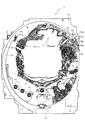
以下、本発明の実施形態について、添付図面を参照して説明する。まず、図1から図35を参照し、第1実施形態として、本発明をパチンコ遊技機(以下、単に「パチンコ機」という)10に適用した場合の一実施形態について説明する。図1は、第1実施形態におけるパチンコ機10の正面図であり、図2はパチンコ機10の遊技盤13の正面図であり、図3はパチンコ機10の背面図である。   Embodiments of the present invention will be described below with reference to the accompanying drawings. First, with reference to FIG. 1 to FIG. 35, an embodiment in which the present invention is applied to a pachinko gaming machine (hereinafter simply referred to as “pachinko machine”) 10 will be described as a first embodiment. 1 is a front view of a pachinko machine 10 according to the first embodiment, FIG. 2 is a front view of a game board 13 of the pachinko machine 10, and FIG. 3 is a rear view of the pachinko machine 10.

図1に示すように、パチンコ機10は、略矩形状に組み合わせた木枠により外殻が形成される外枠11と、その外枠11と略同一の外形形状に形成され外枠11に対して開閉可能に支持された内枠12とを備えている。外枠11には、内枠12を支持するために正面視(図1参照)左側の上下2カ所に金属製のヒンジ18が取り付けられ、そのヒンジ18が設けられた側を開閉の軸として内枠12が正面手前側へ開閉可能に支持されている。   As shown in FIG. 1, the pachinko machine 10 includes an outer frame 11 in which an outer shell is formed by a wooden frame combined in a substantially rectangular shape, and an outer shape that is substantially the same as the outer frame 11. And an inner frame 12 supported to be openable and closable. In order to support the inner frame 12, metal hinges 18 are attached to the outer frame 11 at two upper and lower portions on the left side when viewed from the front (see FIG. 1). The frame 12 is supported so as to be openable and closable to the front front side.

内枠12には、多数の釘や入賞口63,64等を有する遊技盤13(図2参照)が裏面側から着脱可能に装着される。この遊技盤13の前面を球(遊技球)が流下することにより弾球遊技が行われる。なお、内枠12には、球を遊技盤13の前面領域に発射する球発射ユニット112a(図4参照)やその球発射ユニット112aから発射された球を遊技盤13の前面領域まで誘導する発射レール(図示せず)等が取り付けられている。   A game board 13 (see FIG. 2) having a large number of nails, winning holes 63, 64, and the like is detachably mounted on the inner frame 12 from the back side. A ball ball game is played when a ball (game ball) flows down the front of the game board 13. The inner frame 12 has a ball launch unit 112a (see FIG. 4) that launches a ball to the front area of the game board 13 and a launch that guides the ball launched from the ball launch unit 112a to the front area of the game board 13. A rail (not shown) or the like is attached.

内枠12の前面側には、その前面上側を覆う前面枠14と、その下側を覆う下皿ユニット15とが設けられている。前面枠14及び下皿ユニット15を支持するために正面視(図1参照)左側の上下2カ所に金属製のヒンジ19が取り付けられ、そのヒンジ19が設けられた側を開閉の軸として前面枠14及び下皿ユニット15が正面手前側へ開閉可能に支持されている。なお、内枠12の施錠と前面枠14の施錠とは、シリンダ錠20の鍵穴21に専用の鍵を差し込んで所定の操作を行うことでそれぞれ解除される。   On the front side of the inner frame 12, a front frame 14 that covers the upper side of the front surface and a lower dish unit 15 that covers the lower side of the front frame 14 are provided. In order to support the front frame 14 and the lower dish unit 15, metal hinges 19 are attached to two upper and lower portions on the left side when viewed from the front (see FIG. 1), and the side on which the hinges 19 are provided is used as an opening / closing axis. 14 and the lower pan unit 15 are supported so as to be openable and closable toward the front front side. The locking of the inner frame 12 and the locking of the front frame 14 are respectively released by inserting a dedicated key into the key hole 21 of the cylinder lock 20 and performing a predetermined operation.

前面枠14は、装飾用の樹脂部品や電気部品等を組み付けたものであり、その略中央部には略楕円形状に開口形成された窓部14cが設けられている。前面枠14の裏面側には2枚の板ガラスを有するガラスユニット16が配設され、そのガラスユニット16を介して遊技盤13の前面がパチンコ機10の正面側に視認可能となっている。   The front frame 14 is assembled with decorative resin parts, electrical parts, and the like, and a window part 14c that is formed in an approximately elliptical shape is provided at a substantially central part thereof. A glass unit 16 having two plate glasses is disposed on the back side of the front frame 14, and the front surface of the game board 13 can be seen on the front side of the pachinko machine 10 through the glass unit 16.

前面枠14には、球を貯留する上皿17が前方へ張り出して上面を開放した略箱状に形成されており、この上皿17に賞球や貸出球などが排出される。上皿17の底面は正面視(図1参照)右側に下降傾斜して形成され、その傾斜により上皿17に投入された球が球発射ユニット112aへと案内される。また、上皿17の上面には、枠ボタン22が設けられている。この枠ボタン22は、例えば、第3図柄表示装置81(図2参照)で表示される演出のステージを変更したり、スーパーリーチの演出内容を変更したりする場合などに、遊技者により操作される。   On the front frame 14, an upper plate 17 that stores balls is formed in a substantially box shape that protrudes forward and the upper surface is opened, and prize balls and rental balls are discharged to the upper plate 17. The bottom surface of the upper plate 17 is formed to be inclined downward to the right when viewed from the front (see FIG. 1), and the sphere thrown into the upper plate 17 is guided to the ball launch unit 112a by the inclination. A frame button 22 is provided on the upper surface of the upper plate 17. The frame button 22 is operated by the player when, for example, changing the stage of the effect displayed on the third symbol display device 81 (see FIG. 2) or changing the contents of the effect of super reach. The

前面枠14には、その周囲(例えばコーナー部分)に各種ランプ等の発光手段が設けられている。これら発光手段は、大当たり時や所定のリーチ時等における遊技状態の変化に応じて、点灯又は点滅することにより発光態様が変更制御され、遊技中の演出効果を高める役割を果たす。窓部14cの周縁には、LED等の発光手段を内蔵した電飾部29〜33が設けられている。パチンコ機10においては、これら電飾部29〜33が大当たりランプ等の演出ランプとして機能し、大当たり時やリーチ演出時等には内蔵するLEDの点灯や点滅によって各電飾部29〜33が点灯または点滅して、大当たり中である旨、或いは大当たり一歩手前のリーチ中である旨が報知される。また、前面枠14の正面視(図1参照)左上部には、LED等の発光手段が内蔵され賞球の払い出し中とエラー発生時とを表示可能な表示ランプ34が設けられている。   The front frame 14 is provided with light emitting means such as various lamps around it (for example, a corner portion). These light-emitting means play a role of enhancing the effect of the game during the game by changing or controlling the light-emitting mode by turning on or flashing according to the change in the gaming state at the time of big hit or predetermined reach. On the peripheral edge of the window portion 14c, there are provided electric decoration portions 29 to 33 incorporating light emitting means such as LEDs. In the pachinko machine 10, these lighting parts 29 to 33 function as effect lamps such as jackpot lamps, and the lighting parts 29 to 33 are turned on by lighting or blinking of the built-in LEDs at the time of jackpot or reach effects. Alternatively, it blinks to notify that the jackpot is being hit or that the reach is one step before the jackpot. Further, in the upper left part of the front frame 14 as viewed from the front (see FIG. 1), there is provided a display lamp 34 which has built-in light emitting means such as an LED and can display when a prize ball is being paid out and when an error occurs.

また、右側の電飾部32下側には、前面枠14の裏面側を視認できるように裏面側より透明樹脂を取り付けて小窓35が形成され、遊技盤13前面の貼着スペースK1(図2参照)に貼付される証紙等はパチンコ機10の前面から視認可能とされている。また、パチンコ機10においては、より煌びやかさを醸し出すために、電飾部29〜33の周りの領域にクロムメッキを施したABS樹脂製のメッキ部材36が取り付けられている。   In addition, a small window 35 is formed by attaching a transparent resin from the back side so that the back side of the front frame 14 can be visually recognized, on the lower side of the right illumination part 32, and a sticking space K1 on the front side of the game board 13 (FIG. 2) is visible from the front surface of the pachinko machine 10. In addition, in the pachinko machine 10, a plated member 36 made of ABS resin that is chrome-plated is attached to an area around the electric decoration parts 29 to 33 in order to bring out more gorgeousness.

窓部14cの下方には、貸球操作部40が配設されている。貸球操作部40には、度数表示部41と、球貸しボタン42と、返却ボタン43とが設けられている。パチンコ機10の側方に配置されるカードユニット(球貸しユニット)(図示せず)に紙幣やカード等を投入した状態で貸球操作部40が操作されると、その操作に応じて球の貸出が行われる。具体的には、度数表示部41はカード等の残額情報が表示される領域であり、内蔵されたLEDが点灯して残額情報として残額が数字で表示される。球貸しボタン42は、カード等(記録媒体)に記録された情報に基づいて貸出球を得るために操作されるものであり、カード等に残額が存在する限りにおいて貸出球が上皿17に供給される。返却ボタン43は、カードユニットに挿入されたカード等の返却を求める際に操作される。なお、カードユニットを介さずに球貸し装置等から上皿17に球が直接貸し出されるパチンコ機、いわゆる現金機では貸球操作部40が不要となるが、この場合には、貸球操作部40の設置部分に飾りシール等を付加して部品構成は共通のものとしても良い。カードユニットを用いたパチンコ機と現金機との共通化を図ることができる。   A ball rental operation unit 40 is disposed below the window 14c. The ball lending operation unit 40 is provided with a frequency display unit 41, a ball lending button 42, and a return button 43. When the ball lending operation unit 40 is operated in a state where a bill or a card is inserted into a card unit (ball lending unit) (not shown) arranged on the side of the pachinko machine 10, Loans are made. Specifically, the frequency display unit 41 is an area in which the remaining amount information such as a card is displayed, and the built-in LED is lit to display the remaining amount as the remaining amount information. The ball lending button 42 is operated to obtain a lending ball based on information recorded on a card or the like (recording medium), and the lending ball is supplied to the upper plate 17 as long as there is a remaining amount on the card or the like. Is done. The return button 43 is operated when requesting the return of a card or the like inserted into the card unit. In addition, in a pachinko machine in which a ball is lent directly to the upper plate 17 from a ball lending device or the like without using a card unit, a so-called cash machine does not require the ball lending operation unit 40. In this case, the ball lending operation unit 40 It is also possible to add a decorative seal or the like to the installation portion of the parts so that the component configuration is common. A pachinko machine using a card unit and a cash machine can be shared.

上皿17の下側に位置する下皿ユニット15には、その中央部に上皿17に貯留しきれなかった球を貯留するための下皿50が上面を開放した略箱状に形成されている。下皿50の右側には、球を遊技盤13の前面へ打ち込むために遊技者によって操作される操作ハンドル51が配設される。   In the lower plate unit 15 located on the lower side of the upper plate 17, a lower plate 50 for storing a ball that could not be stored in the upper plate 17 is formed in a substantially box shape having an open upper surface. Yes. On the right side of the lower plate 50, an operation handle 51 that is operated by a player to drive a ball into the front surface of the game board 13 is disposed.

操作ハンドル51の内部には、球発射ユニット112aの駆動を許可するためのタッチセンサ51aと、押下操作している期間中には球の発射を停止する発射停止スイッチ51bと、操作ハンドル51の回動操作量(回動位置)を電気抵抗の変化により検出する可変抵抗器(図示せず)などが内蔵されている。操作ハンドル51が遊技者によって右まわりに回動操作されると、タッチセンサ51aがオンされると共に可変抵抗器の抵抗値が回動操作量に対応して変化し、その可変抵抗器の抵抗値に対応した強さ(発射強度)で球が発射され、これにより遊技者の操作に対応した飛び量で遊技盤13の前面へ球が打ち込まれる。また、操作ハンドル51が遊技者により操作されていない状態においては、タッチセンサ51aおよび発射停止スイッチ51bがオフとなっている。   Inside the operation handle 51, a touch sensor 51a for permitting driving of the ball launch unit 112a, a launch stop switch 51b for stopping the launch of the ball during the pressing operation, and a rotation of the operation handle 51. A variable resistor (not shown) that detects the amount of movement (rotation position) based on a change in electrical resistance is incorporated. When the operation handle 51 is rotated clockwise by the player, the touch sensor 51a is turned on, and the resistance value of the variable resistor changes corresponding to the amount of rotation operation. The resistance value of the variable resistor A ball is fired with a strength corresponding to (shooting strength), and the ball is driven into the front surface of the game board 13 with a jump amount corresponding to the player's operation. Further, when the operation handle 51 is not operated by the player, the touch sensor 51a and the firing stop switch 51b are turned off.

下皿50の正面下方部には、下皿50に貯留された球を下方へ排出する際に操作するための球抜きレバー52が設けられている。この球抜きレバー52は、常時、右方向に付勢されており、その付勢に抗して左方向へスライドさせることにより、下皿50の底面に形成された底面口が開口して、その底面口から球が自然落下して排出される。この球抜きレバー52の操作は、通常、下皿50の下方に下皿50から排出された球を受け取る箱(一般に「千両箱」と称される)を置いた状態で行われる。下皿50の右方には、上述したように操作ハンドル51が配設され、下皿50の左方には灰皿53が取り付けられている。   In the lower part of the front of the lower plate 50, a ball removal lever 52 is provided for operating when the balls stored in the lower plate 50 are discharged downward. The ball removal lever 52 is always urged in the right direction. By sliding the ball release lever 52 in the left direction against the urge, the bottom opening formed in the bottom surface of the lower plate 50 is opened. A ball naturally falls from the bottom opening and is discharged. The operation of the ball removal lever 52 is normally performed in a state where a box (generally referred to as “a thousand box”) for receiving the balls discharged from the lower plate 50 is placed below the lower plate 50. As described above, the operation handle 51 is disposed on the right side of the lower plate 50, and the ashtray 53 is attached on the left side of the lower plate 50.

図2に示すように、遊技盤13は、正面視略正方形状に切削加工した木製のベース板60に、球案内用の多数の釘(図示せず)や風車の他、レール61,62、一般入賞口63、第1入球口64、第2入球口640、可変入賞装置65、スルーゲート67、可変表示装置ユニット80等を組み付けて構成され、その周縁部が内枠12(図1参照)の裏面側に取り付けられる。一般入賞口63、第1入球口64、第2入球口640、可変入賞装置65、可変表示装置ユニット80は、ルータ加工によってベース板60に形成された貫通穴に配設され、遊技盤13の前面側から木ネジ等により固定されている。   As shown in FIG. 2, the game board 13 has a wooden base plate 60 cut into a substantially square shape when viewed from the front, a number of nails (not shown) for ball guidance, a windmill, rails 61, 62, The general winning port 63, the first winning port 64, the second winning port 640, the variable winning device 65, the through gate 67, the variable display device unit 80 and the like are assembled, and the peripheral portion thereof is the inner frame 12 (FIG. 1). (See below). The general winning port 63, the first winning port 64, the second winning port 640, the variable winning device 65, and the variable display device unit 80 are disposed in a through hole formed in the base plate 60 by router processing, and the game board 13 is fixed from the front side with a wood screw or the like.

遊技盤13の前面中央部分は、前面枠14の窓部14c(図1参照)を通じて内枠12の前面側から視認することができる。以下に、主に図2を参照して、遊技盤13の構成について説明する。   The front center portion of the game board 13 can be viewed from the front side of the inner frame 12 through the window portion 14c (see FIG. 1) of the front frame 14. The configuration of the game board 13 will be described below mainly with reference to FIG.

遊技盤13の前面には、帯状の金属板を略円弧状に屈曲加工して形成した外レール62が植立され、その外レール62の内側位置には外レール62と同様に帯状の金属板で形成した円弧状の内レール61が植立される。この内レール61と外レール62とにより遊技盤13の前面外周が囲まれ、遊技盤13とガラスユニット16(図1参照)とにより前後が囲まれることにより、遊技盤13の前面には、球の挙動により遊技が行われる遊技領域が形成される。遊技領域は、遊技盤13の前面であって2本のレール61,62とレール間を繋ぐ円弧を内面側に設けて形成された樹脂製の円弧部材(図示せず)とにより区画して形成される略円形状の領域(入賞口等が配設され、発射された球が流下する領域)である。   An outer rail 62 formed by bending a strip-shaped metal plate into a substantially arc shape is planted on the front surface of the game board 13, and the strip-shaped metal plate is located on the inner side of the outer rail 62 in the same manner as the outer rail 62. The arc-shaped inner rail 61 formed by the above is planted. The inner rail 61 and the outer rail 62 surround the outer periphery of the front surface of the game board 13, and the game board 13 and the glass unit 16 (see FIG. 1) surround the front and rear. A game area in which a game is played is formed by the behavior of. The game area is formed by dividing the two rails 61 and 62 on the front surface of the game board 13 and a resin arc member (not shown) formed by providing an arc connecting the rails on the inner surface side. This is a substantially circular region (region in which a winning opening or the like is provided and the launched ball flows down).

2本のレール61,62は、球発射ユニット112a(図4参照)から発射された球を遊技盤13上部へ案内するために設けられたものである。内レール61の先端部分(図2の左上部)には戻り球防止部材68が取り付けられ、一旦、遊技盤13の上部へ案内された球が再度球案内通路内に戻ってしまうといった事態が防止される。外レール62の先端部(図2の右上部)には、球の最大飛翔部分に対応する位置に返しゴム69が取り付けられ、所定以上の勢いで発射された球は、返しゴム69に当たって、勢いが減衰されつつ中央部側へ跳ね返される。また、パチンコ機10の状態では、内レール61の右下側の先端部と外レール62の右上側の先端部との間には、レール間を繋ぐ円弧を内面側に設けて形成された樹脂製の円弧部材がベース板60に当接し固定される。   The two rails 61 and 62 are provided to guide the ball fired from the ball launch unit 112a (see FIG. 4) to the upper part of the game board 13. A return ball preventing member 68 is attached to the front end portion of the inner rail 61 (upper left portion in FIG. 2) to prevent the ball once guided to the upper portion of the game board 13 from returning to the ball guide path again. Is done. A return rubber 69 is attached to the tip of the outer rail 62 (upper right part in FIG. 2) at a position corresponding to the maximum flying portion of the sphere. Is bounced back to the center while being attenuated. Further, in the state of the pachinko machine 10, a resin formed by providing an arc connecting the rails on the inner surface side between the lower right end portion of the inner rail 61 and the upper right end portion of the outer rail 62. The made circular arc member is in contact with and fixed to the base plate 60.

遊技領域の正面視右側上部(図2の右側上部)には、2つの第1図柄表示装置37A,37Bが配設されている。第1図柄表示装置37Aには、発光手段である複数のLED37Aaと7セグメント表示器37Abとが設けられている。他方の第1図柄表示装置37Bもまた同様に、発光手段である複数のLED37Baと7セグメント表示器37Bbとが設けられている。   Two first symbol display devices 37A and 37B are disposed in the upper right portion of the game area when viewed from the front (upper right portion of FIG. 2). The first symbol display device 37A is provided with a plurality of LEDs 37Aa which are light emitting means and a 7-segment display 37Ab. Similarly, the other first symbol display device 37B is provided with a plurality of LEDs 37Ba and a 7-segment display 37Bb which are light emitting means.

第1図柄表示装置37A,37Bは、主制御装置110で行われる各制御に応じた表示がなされるものであり、主にパチンコ機10の遊技状態の表示が行われる。本実施形態では、これらの第1図柄表示装置37A,37Bは、球が、第1入球口64へ入賞したか、第2入球口640へ入賞したかに応じて使い分けられるように構成されている。具体的には、球が、第1入球口64へ入賞した場合には、第1図柄表示装置37Aが作動し、一方で、球が、第2入球口640へ入賞した場合には、第1図柄表示装置37Bが作動するように構成されている。   The first symbol display devices 37 </ b> A and 37 </ b> B display according to each control performed by the main control device 110, and mainly display the gaming state of the pachinko machine 10. In the present embodiment, these first symbol display devices 37 </ b> A and 37 </ b> B are configured to be selectively used depending on whether the ball has won the first entrance 64 or the second entrance 640. ing. Specifically, when the ball wins the first entrance 64, the first symbol display device 37A operates, while when the ball wins the second entrance 640, The first symbol display device 37B is configured to operate.

複数のLED37Aa,37Baは、いずれも、パチンコ機10が確変中か時短中か通常中であるかを点灯状態により示したり、変動中であるか否かを点灯状態により示したり、停止図柄が確変大当たりに対応した図柄か普通大当たりに対応した図柄か外れ図柄であるかを点灯状態により示したり、保留球数を点灯状態により示すものである。7セグメント表示装置37Ab,37Bbは、いずれも、大当たり中のラウンド数やエラー表示を行うものである。なお、LED37Aa,37Baは、それぞれのLEDの発光色(例えば、赤、緑、青)が異なるよう構成され、その発光色の組み合わせにより、少ないLEDでパチンコ機10の各種遊技状態を示唆することができる。   Each of the plurality of LEDs 37Aa and 37Ba indicates whether the pachinko machine 10 is in a certain change, in a short time, or in a normal state by a lighting state, indicates whether or not it is fluctuating by a lighting state, and a stop pattern is definitely changed. Whether the symbol corresponds to the jackpot, the symbol corresponding to the normal jackpot or the off symbol is indicated by a lighting state, or the number of reserved balls is indicated by a lighting state. Each of the 7-segment display devices 37Ab and 37Bb displays the number of rounds that are a big hit and an error display. The LEDs 37Aa and 37Ba are configured so that the emission colors (for example, red, green, and blue) of the respective LEDs are different, and the combination of the emission colors may suggest various gaming states of the pachinko machine 10 with a small number of LEDs. it can.

尚、本パチンコ機10では、第1入球口64及び第2入球口640へ入球があったことを契機として抽選が行われる。パチンコ機10は、その抽選において、大当たりか否かの当否判定(大当たり抽選)を行うと共に、大当たりと判定した場合はその大当たり種別の判定も行う。ここで判定される大当たり種別としては、15R確変大当たり、4R確変大当たり、15R通常大当たりが用意されている。LED37Aa,37Baには、変動終了後の停止図柄として抽選の結果が大当たりであるか否かが示されるだけでなく、大当たりである場合はその大当たり種別に応じた図柄が示される。   In the pachinko machine 10, lottery is performed when the first entrance 64 and the second entrance 640 are entered. In the lottery, the pachinko machine 10 determines whether or not it is a big hit (big hit lottery), and also determines the type of the big hit if it is determined to be a big hit. As the jackpot type determined here, 15R probability variation jackpot, 4R probability variation jackpot, and 15R normal jackpot are prepared. The LEDs 37Aa and 37Ba not only indicate whether or not the lottery result is a jackpot as a stop symbol after the end of the change, but if the jackpot is a jackpot, a symbol corresponding to the jackpot type is displayed.

ここで、「15R確変大当たり」とは、最大ラウンド数が15ラウンドの大当たりの後に高確率状態へ移行する確変大当たりのことであり、「4R確変大当たり」とは、最大ラウンド数が4ラウンドの大当たりの後に高確率状態へ移行する確変大当たりのことである。また、「15R通常大当たり」は、最大ラウンド数が15ラウンドの大当たりの後に、低確率状態へ移行すると共に、所定の変動回数の間(例えば、100変動回数)は時短状態となる大当たりのことである。   Here, “15R probability variation jackpot” is a probability variation jackpot in which the maximum number of rounds shifts to a high probability state after a jackpot of 15 rounds. “4R probability variation jackpot” is a jackpot with a maximum number of rounds of four. It is a probabilistic jackpot that shifts to a high probability state after. In addition, “15R normal jackpot” is a jackpot that shifts to a low probability state after the maximum number of rounds of 15 rounds and hits a short time during a predetermined number of fluctuations (for example, 100 fluctuations). is there.

また、「高確率状態」とは、大当たり終了後に付加価値としてその後の大当たり確率がアップした状態、いわゆる確率変動中(確変中)の時をいい、換言すれば、特別遊技状態へ移行し易い遊技の状態のことである。本実施形態における高確率状態(確変中)は、後述する第2図柄の当たり確率がアップして第2入球口640へ球が入球し易い遊技の状態を含む。「低確率状態」とは、確変中でない時をいい、大当たり確率が通常の状態、即ち、確変の時より大当たり確率が低い状態をいう。また、「低確率状態」のうちの時短状態(時短中)とは、大当たり確率が通常の状態であると共に、大当たり確率がそのままで第2図柄の当たり確率のみがアップして第2入球口640へ球が入球し易い遊技の状態のことをいう。一方、パチンコ機10が通常中とは、確変中でも時短中でもない遊技の状態(大当たり確率も第2図柄の当たり確率もアップしていない状態)である。   In addition, the “high probability state” means a state in which the jackpot probability thereafter increases as an added value after the jackpot ends, that is, when the probability change is in progress (probability change), in other words, a game that easily shifts to the special game state. It is a state of. The high probability state (during probability change) in the present embodiment includes a game state in which the hit probability of the second symbol, which will be described later, is increased and a ball is likely to enter the second entrance 640. The “low probability state” refers to a time when the probability of jackpot change is not occurring, and a state where the jackpot probability is normal, that is, a state where the jackpot probability is lower than that at the time of probability change. The short time state (short time) of the “low probability state” means that the jackpot probability is a normal state, and the jackpot probability remains as it is and only the hit probability of the second symbol is increased. It means a game state in which a ball can easily enter 640. On the other hand, when the pachinko machine 10 is in a normal state is a game state (a state where neither the big hit probability nor the second symbol hit probability is increased) which is neither probabilistic nor short in time.

確変中や時短中は、第2図柄の当たり確率がアップするだけではなく、第2入球口640に付随する電動役物640aが開放される時間も変更され、通常中と比して長い時間が設定される。電動役物640aが開放された状態(開放状態)にある場合は、その電動役物640aが閉鎖された状態(閉鎖状態)にある場合と比して、第2入球口640へ球が入球しやすい状態となる。よって、確変中や時短中は、第2入球口640へ球が入球し易い状態となり、大当たり抽選が行われる回数を増やすことができる。   During probability change and time reduction, not only the probability of hitting the second symbol is increased, but also the time when the electric accessory 640a attached to the second entrance 640 is opened is changed, which is longer than normal Is set. When the electric accessory 640a is in an open state (open state), a ball enters the second entrance 640 as compared with a case where the electric accessory 640a is in a closed state (closed state). It becomes easy to sphere. Thus, during the probability change or during the short time, it becomes easy for the ball to enter the second entrance 640, and the number of jackpot lotteries can be increased.

なお、確変中や時短中において、第2入球口640に付随する電動役物640aの開放時間を変更するのではなく、または、その開放時間を変更することに加えて、1回の当たりで電動役物640aが開放する回数を通常中よりも増やす変更を行うものとしてもよい。また、確変中や時短中において、第2図柄の当たり確率は変更せず、第2入球口640に付随する電動役物640aが開放される時間および1回の当たりで電動役物640aが開放する回数の少なくとも一方を変更するものとしてもよい。また、確変中や時短中において、第2入球口640に付随する電動役物640aが開放される時間や、1回の当たりで電動役物640aを開放する回数はせず、第2図柄の当たり確率だけを、通常中と比してアップするよう変更するものであってもよい。   In addition, during the probability change or in the short time, the opening time of the electric accessory 640a associated with the second entrance 640a is not changed, or in addition to changing the opening time, It is good also as what changes the frequency | count that the electrically-driven accessory 640a opens rather than usual. In addition, the probability of winning the second symbol is not changed during the probability change or in the short time, and the electric accessory 640a is opened at the time when the electric accessory 640a associated with the second entrance 640 is opened and once. It is good also as what changes at least one of the frequency | count to do. In addition, during the probability change or in the short time, the time for opening the electric accessory 640a associated with the second entrance 640 or the number of times of opening the electric accessory 640a per time is not shown. Only the hit probability may be changed so as to be higher than normal.

遊技領域には、球が入賞することにより5個から15個の球が賞球として払い出される複数の一般入賞口63が配設されている。また、遊技領域の中央部分には、可変表示装置ユニット80が配設されている。可変表示装置ユニット80には、第1入球口64及び第2入球口640への入球(始動入賞)をトリガとして、第1図柄表示装置37A,37Bにおける変動表示と同期させながら、第3図柄の変動表示を行う液晶ディスプレイ(以下単に「表示装置」と略す)で構成された第3図柄表示装置81と、スルーゲート67の球の通過をトリガとして第2図柄を変動表示するLEDで構成される第2図柄表示装置(図示せず)とが設けられている。また、可変表示装置ユニット80には、第3図柄表示装置81の外周を囲むようにして、センターフレーム86が配設されている。   The game area is provided with a plurality of general winning ports 63 through which 5 to 15 balls are paid out as winning balls when the balls win. In addition, a variable display device unit 80 is disposed in the central portion of the game area. The variable display device unit 80 has a first entry port 64 and a second entry port 640 as a trigger (start winning prize) as a trigger while synchronizing with the variable display on the first symbol display units 37A and 37B. A third symbol display device 81 composed of a liquid crystal display (hereinafter simply abbreviated as “display device”) for displaying three symbols in a variable manner, and an LED for variably displaying the second symbol with the passage of a ball of the through gate 67 as a trigger. A configured second symbol display device (not shown) is provided. The variable display device unit 80 is provided with a center frame 86 so as to surround the outer periphery of the third symbol display device 81.

第3図柄表示装置81は8インチサイズの大型の液晶ディスプレイで構成されるものであり、表示制御装置114(図4参照)によって表示内容が制御されることにより、例えば上、中及び下の3つの図柄列が表示される。各図柄列は複数の図柄(第3図柄)によって構成され、これらの第3図柄が図柄列毎に横スクロールして第3図柄表示装置81の表示画面上にて第3図柄が可変表示されるようになっている。本実施形態の第3図柄表示装置81は、主制御装置110(図4参照)の制御に伴った遊技状態の表示が第1図柄表示装置37で行われるのに対して、その第1図柄表示装置37の表示に応じた装飾的な表示を行うものである。なお、表示装置に代えて、例えばリール等を用いて第3図柄表示装置81を構成するようにしても良い。   The third symbol display device 81 is constituted by a large liquid crystal display of 8 inch size, and the display content is controlled by the display control device 114 (see FIG. 4). One symbol row is displayed. Each symbol row is composed of a plurality of symbols (third symbol). These third symbols are horizontally scrolled for each symbol column, and the third symbol is variably displayed on the display screen of the third symbol display device 81. It is like that. In the third symbol display device 81 of the present embodiment, the display of the gaming state accompanying the control of the main controller 110 (see FIG. 4) is performed on the first symbol display device 37, whereas the first symbol display thereof is performed. A decorative display corresponding to the display of the device 37 is performed. Instead of the display device, the third symbol display device 81 may be configured using, for example, a reel.

第2図柄表示装置は、球がスルーゲート67を通過する毎に表示図柄(第2図柄(図示せず))としての「○」の図柄と「×」の図柄とを所定時間交互に点灯させる変動表示を行うものである。パチンコ機10では、球がスルーゲート67を通過したことが検出されると、当たり抽選が行われる。その当たり抽選の結果、当たりであれば、第2図柄表示装置において、第2図柄の変動表示後に「○」の図柄が停止表示される。また、当たり抽選の結果、外れであれば、第2図柄表示装置において、第3図柄の変動表示後に「×」の図柄が停止表示される。   Each time the ball passes through the through gate 67, the second symbol display device alternately turns on the symbol “◯” and the symbol “X” as a display symbol (second symbol (not shown)) for a predetermined time. A variable display is performed. In the pachinko machine 10, when it is detected that the ball has passed through the through gate 67, a winning lottery is performed. As a result of the winning lottery, if the winning symbol is a winning symbol, the symbol “◯” is stopped and displayed on the second symbol display device after the variation of the second symbol is displayed. Further, if the winning lottery results, the symbol of “x” is stopped and displayed on the second symbol display device after the variation of the third symbol is displayed.

パチンコ機10は、第2図柄表示装置における変動表示が所定図柄(本実施形態においては「○」の図柄)で停止した場合に、第2入球口640に付随された電動役物640aが所定時間だけ作動状態となる(開放される)よう構成されている。   In the pachinko machine 10, when the variable display on the second symbol display device stops at a predetermined symbol (in this embodiment, a symbol “◯”), the electric accessory 640a attached to the second entrance 640 is predetermined. It is configured to be activated (opened) only for a period of time.

第2図柄の変動表示にかかる時間は、遊技状態が通常中の場合よりも、確変中または時短中の方が短くなるように設定される。これにより、確変中および時短中は、第2図柄の変動表示が短い時間で行われるので、当たり抽選を通常中よりも多く行うことができる。よって、当たり抽選において当たりとなる機会が増えるので、第2入球口640の電動役物640aが開放状態となる機会を遊技者に多く与えることができる。よって、確変中および時短中は、第2入球口640へ球が入球しやすい状態とすることができる。   The time required for the variable display of the second symbol is set to be shorter during the probability change or during the shorter time than when the game state is normal. As a result, during the probability change and during the time reduction, since the variation display of the second symbol is performed in a short time, the winning lottery can be performed more than during normal. Therefore, since the chance of winning in the winning lottery increases, it is possible to give the player many opportunities for the electric accessory 640a of the second entrance 640 to be opened. Therefore, it is possible to make it easier for the ball to enter the second entrance 640 during the probability change and during the time reduction.

なお、確変中または時短中において、当たり確率を高める、1回に当たりに対する電動役物640aの開放時間や開放回数を増やすなど、その他の方法によっても、確変中または時短中に第2入球口640へ球が入球しやすい状態としている場合は、第2図柄の変動表示にかかる時間を遊技状態にかかわらず一定としてもよい。一方、第2図柄の変動表示にかかる時間を、確変中または時短中において通常中よりも短く設定する場合は、当たり確率を遊技状態にかかわらず一定にしてもよいし、また、1回の当たりに対する電動役物640aの開放時間や開放回数を遊技状態にかかわらず一定にしてもよい。   It should be noted that the second entrance 640 may be changed during the probability change or in a short time by other methods such as increasing the probability of hitting during the probability change or in the time reduction, or increasing the opening time or the number of times of opening of the electric accessory 640a per hit. When the ball is in a state where it is easy to enter the ball, the time required for the variable display of the second symbol may be constant regardless of the gaming state. On the other hand, when the time required for displaying the variation of the second symbol is set shorter than normal during probability change or short time, the winning probability may be constant regardless of the gaming state, The opening time and the number of opening times of the electric accessory 640a may be constant regardless of the gaming state.

スルーゲート67は、可変表示装置ユニット80の右方において遊技盤に組み付けられ、遊技盤に発射された球のうち、遊技盤の右方を流下する球の一部が通過可能に構成されている。スルーゲート67を球が通過すると、第2図柄の当たり抽選が行われる。当たり抽選の後、第2図柄表示装置にて変動表示を行い、当たり抽選の結果が当たりであれば、変動表示の停止図柄として「○」の図柄を表示し、当たり抽選の結果が外れであれば、変動表示の停止図柄として「×」の図柄を表示する。   The through gate 67 is assembled to the game board on the right side of the variable display device unit 80, and is configured so that a part of the ball flowing down to the right of the game board can pass through the balls launched to the game board. . When the ball passes through the through gate 67, a winning lottery of the second symbol is performed. After winning the lottery, the 2nd symbol display device displays the variation. For example, the symbol “x” is displayed as the stop symbol of the variable display.

球のスルーゲート67の通過回数は、合計で最大4回まで保留され、その保留球数が上述した第1図柄表示装置37により表示されると共に第2図柄保留ランプ(図示せず)においても点灯表示される。第2図柄保留ランプは、最大保留数分の4つ設けられ、第3図柄表示装置81の下方に左右対称に配設されている。   The total number of passes through the through-gate 67 of the sphere is reserved up to a total of 4 times, and the number of spheres retained is displayed on the first symbol display device 37 described above and also lit on the second symbol hold lamp (not shown). Is displayed. Four second symbol holding lamps are provided for the maximum number of holdings, and are arranged symmetrically below the third symbol display device 81.

なお、第2図柄の変動表示は、本実施形態のように、第2図柄表示装置において複数のランプの点灯と非点灯を切り換えることにより行うものの他、第1図柄表示装置37及び第3図柄表示装置81の一部を使用して行うようにしても良い。同様に、第2図柄保留ランプの点灯を第3図柄表示装置81の一部で行うようにしても良い。また、スルーゲート67の球の通過に対する最大保留球数は4回に限定されるものでなく、3回以下、又は、5回以上の回数(例えば、8回)に設定しても良い。また、スルーゲートの組み付け数は1つに限定されるものではなく、複数(例えば、2つ)であっても良い。また、スルーゲートの組み付け位置は可変表示装置ユニット80の右方に限定されるものではなく、例えば、可変表示装置ユニット80の左方でも良い。また、第1図柄表示装置37により保留球数が示されるので、第2図柄保留ランプにより点灯表示を行わないものとしてもよい。   In addition, the variable display of the second symbol is performed by switching on and off of a plurality of lamps in the second symbol display device as in the present embodiment, as well as the first symbol display device 37 and the third symbol display. You may make it carry out using a part of apparatus 81. FIG. Similarly, the second symbol holding lamp may be turned on by a part of the third symbol display device 81. Further, the maximum number of balls held for passing through the ball of the through gate 67 is not limited to four times, and may be set to three times or less, or five times or more (for example, eight times). Further, the number of through gates to be assembled is not limited to one, but may be plural (for example, two). Further, the assembly position of the through gate is not limited to the right side of the variable display device unit 80, and may be the left side of the variable display device unit 80, for example. Moreover, since the number of reserved balls is shown by the 1st symbol display apparatus 37, it is good also as not performing a lighting display by a 2nd symbol hold lamp.

可変表示装置ユニット80の下方には、球が入球し得る第1入球口64が配設されている。この第1入球口64へ球が入球すると遊技盤13の裏面側に設けられる第1入球口スイッチ(図示せず)がオンとなり、その第1入球口スイッチのオンに起因して主制御装置110(図4参照)で大当たりの抽選がなされ、その抽選結果に応じた表示が第1図柄表示装置37AのLED37Aaで示される。   Below the variable display device unit 80, a first entrance 64 into which a sphere can enter is disposed. When a ball enters the first entrance 64, a first entrance switch (not shown) provided on the back side of the game board 13 is turned on, and the first entrance switch is turned on. The main control device 110 (see FIG. 4) draws a jackpot, and a display corresponding to the lottery result is indicated by the LED 37Aa of the first symbol display device 37A.

一方、第1入球口64の正面視下方には、球が入球し得る第2入球口640が配設されている。この第2入球口640へ球が入球すると遊技盤13の裏面側に設けられる第2入球口スイッチ(図示せず)がオンとなり、その第2入球口スイッチのオンに起因して主制御装置110(図4参照)で大当たりの抽選がなされ、その抽選結果に応じた表示が第1図柄表示装置37BのLED37Baで示される。   On the other hand, a second entrance 640 through which a sphere can enter is disposed below the first entrance 64 in front view. When a ball enters the second entrance 640, a second entrance switch (not shown) provided on the back side of the game board 13 is turned on, and the second entrance switch is turned on. The main control device 110 (see FIG. 4) performs a lottery lottery, and the display corresponding to the lottery result is indicated by the LED 37Ba of the first symbol display device 37B.

また、第1入球口64および第2入球口640は、それぞれ、球が入球すると5個の球が賞球として払い出される入賞口の1つにもなっている。なお、本実施形態においては、第1入球口64へ球が入球した場合に払い出される賞球数と第2入球口640へ球が入球した場合に払い出される賞球数とを同じに構成したが、第1入球口64へ球が入球した場合に払い出される賞球数と第2入球口640へ球が入球した場合に払い出される賞球数とを異なる数、例えば、第1入球口64へ球が入球した場合に払い出される賞球数を3個とし、第2入球口640へ球が入球した場合に払い出される賞球数を5個として構成してもよい。   Each of the first entrance 64 and the second entrance 640 is also one of the entrances for paying out 5 balls as prize balls when a ball enters. In the present embodiment, the number of prize balls paid out when a ball enters the first entrance 64 and the number of prize balls paid out when a ball enters the second entrance 640 are the same. However, the number of prize balls to be paid out when a ball enters the first entrance 64 is different from the number of prize balls to be paid out when a ball enters the second entrance 640, for example, The number of prize balls to be paid out when a ball enters the first entrance 64 is three, and the number of prize balls to be paid out when a ball enters the second entrance 640 is five. May be.

第2入球口640には電動役物640aが付随されている。この電動役物640aは開閉可能に構成されており、通常は電動役物640aが閉鎖状態(縮小状態)となって、球が第2入球口640へ入球しにくい状態となっている。一方、スルーゲート67への球の通過を契機として行われる第2図柄の変動表示の結果、「○」の図柄が第2図柄表示装置に表示された場合、電動役物640aが開放状態(拡大状態)となり、球が第2入球口640へ入球しやすい状態となる。   The second entrance 640 is accompanied by an electric accessory 640a. The electric combination 640a is configured to be openable and closable. Normally, the electric combination 640a is in a closed state (reduced state), and it is difficult for the ball to enter the second entrance 640. On the other hand, when the symbol “◯” is displayed on the second symbol display device as a result of the variation display of the second symbol that is triggered by the passage of the ball to the through gate 67, the electric accessory 640a is in an open state (enlarged) State), and the ball easily enters the second entrance 640.

上述した通り、確変中および時短中は、通常中と比して第2図柄の当たり確率が高く、また、第2図柄の変動表示にかかる時間も短いので、第2図柄の変動表示において「○」の図柄が表示され易くなって、電動役物640aが開放状態(拡大状態)となる回数が増える。更に、確変中および時短中は、電動役物640aが開放される時間も、通常中より長くなる。よって、確変中および時短中は、通常時と比して、第2入球口640へ球が入球しやすい状態を作ることができる。   As described above, the probability of hitting the second symbol is higher than that during normal change during the probability change and the short time, and the time required for the variation display of the second symbol is short. "Is easily displayed, and the number of times that the electric accessory 640a is opened (enlarged) is increased. Further, during the probability change and the time reduction, the time for opening the electric accessory 640a also becomes longer than during the normal time. Therefore, it is possible to create a state in which the ball is likely to enter the second entrance 640 during the probability change and during the short time compared to the normal time.

ここで、第1入球口64に球が入球した場合と第2入球口640へ球が入球した場合とで、大当たりとなる確率は、低確率状態であっても高確率状態でも同一である。しかしながら、大当たりとなった場合に選定される大当たりの種別として15R確変大当たりとなる確率は、第2入球口640へ球が入球した場合のほうが第1入球口64へ球が入球した場合よりも高く設定されている。一方、第1入球口64は、第2入球口640にあるような電動役物は有しておらず、球が常時入球可能な状態となっている。   Here, the probability of a big hit between when the ball enters the first entrance 64 and when the ball enters the second entrance 640 is low or high. Are the same. However, the probability of a 15R probability variable jackpot as the jackpot type selected when the jackpot is won is that the ball enters the first slot 64 when the ball enters the second slot 640. It is set higher than the case. On the other hand, the first entrance 64 does not have an electric accessory as in the second entrance 640 and is in a state in which a ball can always enter.

よって、通常中においては、第2入球口640に付随する電動役物が閉鎖状態にある場合が多く、第2入球口640に入球しづらいので、電動役物のない第1入球口64へ向けて、可変表示装置ユニット80の左方を球が通過するように球を発射し(所謂「左打ち」)、第1入球口64への入球によって大当たり抽選の機会を多く得て、大当たりとなることを狙った方が、遊技者にとって有利となる。   Therefore, during normal times, the electric accessory associated with the second entrance 640 is often in a closed state, and it is difficult to enter the second entrance 640, so the first entrance without the electric accessory The ball is fired toward the mouth 64 so that the ball passes through the left side of the variable display device unit 80 (so-called “left-handed”), and the chance to win a lottery is increased by entering the first entrance 64. It is advantageous for the player to aim for a big hit.

一方、確変中や時短中は、スルーゲート67に球を通過させることで、第2入球口640に付随する電動役物640aが開放状態となりやすく、第2入球口640に入球しやすい状態であるので、第2入球口640へ向けて、可変表示装置80の右方を球が通過するように球を発射し(所謂「右打ち」)、スルーゲート67を通過させて電動役物を開放状態にすると共に、第2入球口640への入球によって15R確変大当たりとなることを狙った方が、遊技者にとって有利となる。   On the other hand, during probability change and time reduction, by passing the ball through the through gate 67, the electric accessory 640a associated with the second entrance 640 is likely to be in an open state, and it is easy to enter the second entrance 640. Since it is in a state, the ball is fired toward the second entrance 640 so that the ball passes the right side of the variable display device 80 (so-called “right-handed”), and passes through the through gate 67 to be electrically operated. It is advantageous for the player to open the object and aim to win 15R probability variation by entering the second entrance 640.

このように、本実施形態のパチンコ機10は、パチンコ機10の遊技状態(確変中であるか、時短中であるか、通常中であるか)に応じて、遊技者に対し、球の発射の仕方を「左打ち」と「右打ち」とに変えさせることができる。よって、遊技者に対して、球の打ち方に変化をもたらすことができるので、遊技を楽しませることができる。   As described above, the pachinko machine 10 according to the present embodiment launches a ball to the player in accordance with the gaming state of the pachinko machine 10 (whether it is probable, short, or normal). Can be changed between “left-handed” and “right-handed”. Thus, the player can be changed in the way the ball is hit, so that the game can be enjoyed.

第1入球口64の右方には可変入賞装置65が配設されており、その略中央部分に横長矩形状の特定入賞口(大開放口)65aが設けられている。パチンコ機10においては、第1入球口64又は第2入球口640への入球に起因して行われた大当たり抽選が大当たりとなると、所定時間(変動時間)が経過した後に、大当たりの停止図柄となるよう第1図柄表示装置37AのLED37Aa又は第1図柄表示装置37BのLED37Baを点灯させると共に、その大当たりに対応した停止図柄を第3図柄表示装置81に表示させて、大当たりの発生が示される。その後、球が入賞し易い特別遊技状態(大当たり)に遊技状態が遷移する。この特別遊技状態として、通常時には閉鎖されている特定入賞口65aが、所定時間(例えば、30秒経過するまで、或いは、球が10個入賞するまで)開放される。   A variable winning device 65 is disposed on the right side of the first winning hole 64, and a horizontally-long rectangular specific winning opening (large opening) 65a is provided at a substantially central portion thereof. In the pachinko machine 10, when the jackpot lottery performed due to entering the first entrance 64 or the second entrance 640 becomes a big win, after a predetermined time (fluctuation time) has passed, The LED 37Aa of the first symbol display device 37A or the LED 37Ba of the first symbol display device 37B is turned on so as to become a stop symbol, and the stop symbol corresponding to the jackpot is displayed on the third symbol display device 81, so that a big hit is generated. Indicated. Thereafter, the gaming state transitions to a special gaming state (big hit) where the ball is easy to win. In this special gaming state, the special winning opening 65a that is normally closed is opened for a predetermined time (for example, until 30 seconds have elapsed or ten balls have been won).

この特定入賞口65aは、所定時間が経過すると閉鎖され、その閉鎖後、再度、その特定入賞口65aが所定時間開放される。この特定入賞口65aの開閉動作は、最高で例えば15回(15ラウンド)繰り返し可能にされている。この開閉動作が行われている状態が、遊技者にとって有利な特別遊技状態の一形態であり、遊技者には、遊技上の価値(遊技価値)の付与として通常時より多量の賞球の払い出しが行われる。   The specific winning opening 65a is closed when a predetermined time elapses, and after the closing, the specific winning opening 65a is opened again for a predetermined time. The opening / closing operation of the specific winning opening 65a can be repeated up to 15 times (15 rounds), for example. The state in which the opening / closing operation is performed is a form of a special gaming state advantageous to the player, and the player is given out a larger amount of prize balls than usual in order to give a gaming value (game value). Is done.

可変入賞装置65は、具体的には、特定入賞口65aを覆う横長矩形状の開閉板と、その開閉板の下辺を軸として前方側に開閉駆動するための大開放口ソレノイド(図示せず)とをいずれも備えている。特定入賞口65aは、通常時は、球が入賞できないか又は入賞し難い閉状態になっている。大当たりの際には大開放口ソレノイドを駆動して開閉板を前面下側に傾倒し、球が特定入賞口65aに入賞しやすい開状態を一時的に形成し、その開状態と通常時の閉状態との状態を交互に繰り返すように作動する。   Specifically, the variable winning device 65 is a horizontally long rectangular opening / closing plate covering the specific winning opening 65a, and a large opening opening solenoid (not shown) for driving to open / close forward with the lower side of the opening / closing plate as an axis. And both. The special winning opening 65a is normally closed so that the ball cannot win or is difficult to win. In the case of a big hit, the large opening opening solenoid is driven to tilt the opening / closing plate to the lower front side to temporarily form an open state in which the ball is likely to win the specific winning opening 65a. It operates to repeat the state and the state alternately.

なお、上記した形態に特別遊技状態は限定されるものではない。特定入賞口65aとは別に開閉される大開放口を遊技領域に設け、第1図柄表示装置37A,37Bにおいて大当たりに対応したLED37Aa,LED37Baが点灯した場合に、特定入賞口65aが所定時間開放され、その特定入賞口65aの開放中に、球が特定入賞口65a内へ入賞することを契機として特定入賞口65aとは別に設けられた大開放口が所定時間、所定回数開放される遊技状態を特別遊技状態として形成するようにしても良い。また、特定入賞口65aは1つに限るものではなく、複数(例えば2つ)配置しても良く、また配置位置も第1入球口64の右方に限らず、例えば、可変表示装置ユニット80の左方でも良い。   Note that the special gaming state is not limited to the above-described form. When the game area is provided with a large opening that is opened and closed separately from the specific winning port 65a, and the LED 37Aa and LED 37Ba corresponding to the jackpot are turned on in the first symbol display devices 37A and 37B, the specific winning port 65a is opened for a predetermined time. A gaming state in which a large opening provided separately from the specific winning opening 65a is opened a predetermined number of times for a predetermined time when the ball wins into the specific winning opening 65a while the specific winning opening 65a is opened. You may make it form as a special game state. Further, the number of the specific winning openings 65a is not limited to one, and a plurality (for example, two) may be arranged, and the arrangement position is not limited to the right side of the first entrance 64, for example, a variable display device unit. The left side of 80 is also acceptable.

遊技盤13の下側における中央部及び右隅部には、証紙や識別ラベル等を貼着するための貼着スペースK1,K2が設けられ、貼着スペースK1に貼られた証紙等は、前面枠14の小窓35(図1参照)を通じて視認することができる。   Adhesive spaces K1 and K2 for adhering stamps and identification labels are provided at the center and right corner on the lower side of the game board 13, and the stamps and the like pasted on the adhering space K1 are It can be visually recognized through the small window 35 (see FIG. 1) of the frame 14.

更に、遊技盤13には、アウト口66が設けられている。いずれの入賞口63,64,65a,640,にも入球しなかった球はアウト口66を通って図示しない球排出路へと案内される。遊技盤13には、球の落下方向を適宜分散、調整等するために多数の釘が植設されているとともに、風車等の各種部材(役物)が配設されている。   Further, the game board 13 is provided with an out port 66. A ball that has not entered any of the winning openings 63, 64, 65a, 640 is guided to a ball discharge path (not shown) through the out opening 66. A number of nails are planted on the game board 13 in order to appropriately disperse and adjust the falling direction of the ball, and various members (instruments) such as a windmill are arranged.

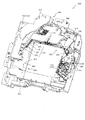
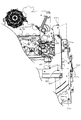
図3に示すように、パチンコ機10の背面側には、制御基板ユニット90,91と、裏パックユニット94とが主に備えられている。制御基板ユニット90は、主基板(主制御装置110)と音声ランプ制御基板(音声ランプ制御装置113)と表示制御基板(表示制御装置114)とが搭載されてユニット化されている。制御基板ユニット91は、払出制御基板(払出制御装置111)と発射制御基板(発射制御装置112)と電源基板(電源装置115)とカードユニット接続基板116とが搭載されてユニット化されている。   As shown in FIG. 3, control board units 90 and 91 and a back pack unit 94 are mainly provided on the back side of the pachinko machine 10. The control board unit 90 is unitized by mounting a main board (main control apparatus 110), an audio lamp control board (audio lamp control apparatus 113), and a display control board (display control apparatus 114). The control board unit 91 is unitized by mounting a payout control board (payout control apparatus 111), a firing control board (launching control apparatus 112), a power supply board (power supply apparatus 115), and a card unit connection board 116.

裏パックユニット94は、保護カバー部を形成する裏パック92と払出ユニット93とがユニット化されている。また、各制御基板には、各制御を司る1チップマイコンとしてのMPU、各種機器との連絡をとるポート、各種抽選の際に用いられる乱数発生器、時間計数や同期を図る場合などに使用されるクロックパルス発生回路等が、必要に応じて搭載されている。   The back pack unit 94 includes a back pack 92 and a dispensing unit 93 that form a protective cover. In addition, each control board is used for MPU as a one-chip microcomputer that controls each control, a port for communicating with various devices, a random number generator used for various lotteries, time counting and synchronization. A clock pulse generation circuit or the like is mounted as necessary.

なお、主制御装置110、音声ランプ制御装置113及び表示制御装置114、払出制御装置111及び発射制御装置112、電源装置115、カードユニット接続基板116は、それぞれ基板ボックス100〜104に収納されている。基板ボックス100〜104は、ボックスベースと該ボックスベースの開口部を覆うボックスカバーとを備えており、そのボックスベースとボックスカバーとが互いに連結されて、各制御装置や各基板が収納される。   The main control device 110, the sound lamp control device 113 and the display control device 114, the payout control device 111 and the firing control device 112, the power supply device 115, and the card unit connection board 116 are housed in the board boxes 100 to 104, respectively. . The board boxes 100 to 104 include a box base and a box cover that covers the opening of the box base. The box base and the box cover are connected to each other, and each control device and each board are accommodated.

また、基板ボックス100(主制御装置110)及び基板ボックス102(払出制御装置111及び発射制御装置112)は、ボックスベースとボックスカバーとを封印ユニット(図示せず)によって開封不能に連結(かしめ構造による連結)している。また、ボックスベースとボックスカバーとの連結部には、ボックスベースとボックスカバーとに亘って封印シール(図示せず)が貼着されている。この封印シールは、脆性な素材で構成されており、基板ボックス100,102を開封するために封印シールを剥がそうとしたり、基板ボックス100,102を無理に開封しようとすると、ボックスベース側とボックスカバー側とに切断される。よって、封印ユニット又は封印シールを確認することで、基板ボックス100,102が開封されたかどうかを知ることができる。   Further, the substrate box 100 (main control device 110) and the substrate box 102 (dispensing control device 111 and launch control device 112) connect the box base and the box cover so that they cannot be opened by a sealing unit (not shown) (caulking structure). Consolidated). In addition, a seal (not shown) is attached to the connecting portion between the box base and the box cover so as to cover the box base and the box cover. This seal seal is made of a brittle material. If the seal is to be peeled off in order to open the substrate boxes 100, 102, or if the substrate boxes 100, 102 are forcibly opened, the box base side and the box cover are removed. Cut to the side. Therefore, it is possible to know whether or not the substrate boxes 100 and 102 have been opened by checking the sealing unit or the sealing seal.

払出ユニット93は、裏パックユニット94の最上部に位置して上方に開口したタンク130と、タンク130の下方に連結され下流側に向けて緩やかに傾斜するタンクレール131と、タンクレール131の下流側に縦向きに連結されるケースレール132と、ケースレール132の最下流部に設けられ、払出モータ216(図4参照)の所定の電気的構成により球の払出を行う払出装置133とを備えている。タンク130には、遊技ホールの島設備から供給される球が逐次補給され、払出装置133により必要個数の球の払い出しが適宜行われる。タンクレール131には、当該タンクレール131に振動を付加するためのバイブレータ134が取り付けられている。   The payout unit 93 includes a tank 130 that is located at the top of the back pack unit 94 and opens upward, a tank rail 131 that is connected to the lower side of the tank 130 and is gently inclined toward the downstream side, and downstream of the tank rail 131. A case rail 132 that is vertically connected to the side, and a payout device 133 that is provided at the most downstream portion of the case rail 132 and that pays out a ball by a predetermined electrical configuration of the payout motor 216 (see FIG. 4). ing. The tank 130 is successively replenished with balls supplied from the island equipment of the game hall, and a required number of balls are paid out by the payout device 133 as appropriate. A vibrator 134 for applying vibration to the tank rail 131 is attached to the tank rail 131.

また、払出制御装置111には状態復帰スイッチ120が設けられ、発射制御装置112には可変抵抗器の操作つまみ121が設けられ、電源装置115にはRAM消去スイッチ122が設けられている。状態復帰スイッチ120は、例えば、払出モータ216(図4参照)部の球詰まり等、払出エラーの発生時に球詰まりを解消(正常状態への復帰)するために操作される。操作つまみ121は、発射ソレノイドの発射力を調整するために操作される。RAM消去スイッチ122は、パチンコ機10を初期状態に戻したい場合に電源投入時に操作される。   The payout control device 111 is provided with a state return switch 120, the firing control device 112 is provided with a variable resistor operation knob 121, and the power supply device 115 is provided with a RAM erase switch 122. The state return switch 120 is operated, for example, to eliminate ball clogging (return to a normal state) when a payout error occurs, such as ball clogging in the payout motor 216 (see FIG. 4). The operation knob 121 is operated to adjust the firing force of the firing solenoid. The RAM erase switch 122 is operated when the power is turned on to return the pachinko machine 10 to the initial state.

次に、図4を参照して、本パチンコ機10の電気的構成について説明する。図4は、パチンコ機10の電気的構成を示すブロック図である。   Next, the electrical configuration of the pachinko machine 10 will be described with reference to FIG. FIG. 4 is a block diagram showing an electrical configuration of the pachinko machine 10.

主制御装置110には、演算装置である1チップマイコンとしてのMPU201が搭載されている。MPU201には、該MPU201により実行される各種の制御プログラムや固定値データを記憶したROM202と、そのROM202内に記憶される制御プログラムの実行に際して各種のデータ等を一時的に記憶するためのメモリであるRAM203と、そのほか、割込回路やタイマ回路、データ送受信回路などの各種回路が内蔵されている。主制御装置110では、MPU201によって、大当たり抽選や第1図柄表示装置37および第3図柄表示装置81における表示の設定、第2図柄表示装置における表示結果の抽選といったパチンコ機10の主要な処理を実行する。   The main controller 110 is equipped with an MPU 201 as a one-chip microcomputer that is an arithmetic unit. The MPU 201 includes a ROM 202 that stores various control programs executed by the MPU 201 and fixed value data, and a memory that temporarily stores various data when the control program stored in the ROM 202 is executed. A certain RAM 203 and various other circuits such as an interrupt circuit, a timer circuit, and a data transmission / reception circuit are incorporated. In the main controller 110, the MPU 201 executes main processing of the pachinko machine 10 such as jackpot lottery, display setting in the first symbol display device 37 and the third symbol display device 81, and lottery of display results in the second symbol display device. To do.

なお、払出制御装置111や音声ランプ制御装置113などのサブ制御装置に対して動作を指示するために、主制御装置110から該サブ制御装置へ各種のコマンドがデータ送受信回路によって送信されるが、かかるコマンドは、主制御装置110からサブ制御装置へ一方向にのみ送信される。   Various commands are transmitted from the main control device 110 to the sub control device by the data transmission / reception circuit in order to instruct the sub control device such as the payout control device 111 and the sound lamp control device 113 to operate. Such a command is transmitted from the main controller 110 to the sub controller only in one direction.

RAM203は、各種エリア、カウンタ、フラグのほか、MPU201の内部レジスタの内容やMPU201により実行される制御プログラムの戻り先番地などが記憶されるスタックエリアと、各種のフラグおよびカウンタ、I/O等の値が記憶される作業エリア(作業領域)とを有している。なお、RAM203は、パチンコ機10の電源の遮断後においても電源装置115からバックアップ電圧が供給されてデータを保持(バックアップ)できる構成となっており、RAM203に記憶されるデータは、すべてバックアップされる。   The RAM 203 stores various areas, counters, flags, a stack area for storing the contents of the internal registers of the MPU 201 and a return address of a control program executed by the MPU 201, various flags, counters, I / O, and the like. And a work area (work area) in which values are stored. Note that the RAM 203 is configured so that the backup voltage is supplied from the power supply device 115 and the data can be retained (backed up) even after the power of the pachinko machine 10 is shut off, and all data stored in the RAM 203 is backed up. .

停電などの発生により電源が遮断されると、その電源遮断時(停電発生時を含む。以下同様)のスタックポインタや、各レジスタの値がRAM203に記憶される。一方、電源投入時(停電解消による電源投入を含む。以下同様)には、RAM203に記憶される情報に基づいて、パチンコ機10の状態が電源遮断前の状態に復帰される。RAM203への書き込みはメイン処理(図示せず)によって電源遮断時に実行され、RAM203に書き込まれた各値の復帰は電源投入時の立ち上げ処理(図示せず)において実行される。なお、MPU201のNMI端子(ノンマスカブル割込端子)には、停電等の発生による電源遮断時に、停電監視回路252からの停電信号SG1が入力されるように構成されており、その停電信号SG1がMPU201へ入力されると、停電時処理としてのNMI割込処理(図示せず)が即座に実行される。   When the power is shut down due to the occurrence of a power failure or the like, the stack pointer and the value of each register when the power is shut off (including when the power failure occurs, the same applies hereinafter) are stored in RAM 203. On the other hand, at the time of power-on (including power-on due to power failure cancellation, the same applies hereinafter), the state of the pachinko machine 10 is restored to the state before power-off based on information stored in the RAM 203. Writing to the RAM 203 is executed when the power is shut off by a main process (not shown), and restoration of each value written to the RAM 203 is executed in a start-up process (not shown) when the power is turned on. Note that the power failure signal SG1 from the power failure monitoring circuit 252 is input to the NMI terminal (non-maskable interrupt terminal) of the MPU 201 when the power is interrupted due to the occurrence of a power failure or the like. Is input immediately, an NMI interrupt process (not shown) as a power failure process is immediately executed.

主制御装置110のMPU201には、アドレスバス及びデータバスで構成されるバスライン204を介して入出力ポート205が接続されている。入出力ポート205には、払出制御装置111、音声ランプ制御装置113、第1図柄表示装置37、第2図柄表示装置、第2図柄保留ランプ、特定入賞口65aの開閉板の下辺を軸として前方側に開閉駆動するための大開放口ソレノイドや電動役物を駆動するためのソレノイドなどからなるソレノイド209が接続され、MPU201は、入出力ポート205を介してこれらに対し各種コマンドや制御信号を送信する。   An input / output port 205 is connected to the MPU 201 of the main control device 110 via a bus line 204 composed of an address bus and a data bus. The input / output port 205 has a payout control device 111, a sound lamp control device 113, a first symbol display device 37, a second symbol display device, a second symbol holding lamp, and a front with the lower side of the opening / closing plate of the specific winning opening 65a as an axis. A solenoid 209 made up of a large opening solenoid for opening / closing and a solenoid for driving an electric accessory is connected to the side, and the MPU 201 transmits various commands and control signals to these via the input / output port 205. To do.

また、入出力ポート205には、図示しないスイッチ群およびスライド位置検出センサSや回転位置検出センサRを含むセンサ群などからなる各種スイッチ208、電源装置115に設けられた後述のRAM消去スイッチ回路253が接続され、MPU201は各種スイッチ208から出力される信号や、RAM消去スイッチ回路253より出力されるRAM消去信号SG2に基づいて各種処理を実行する。   The input / output port 205 includes a switch group (not shown), various switches 208 including a sensor group including a slide position detection sensor S and a rotation position detection sensor R, and a RAM erase switch circuit 253 described later provided in the power supply device 115. Are connected, and the MPU 201 executes various processes based on signals output from the various switches 208 and the RAM erase signal SG2 output from the RAM erase switch circuit 253.

払出制御装置111は、払出モータ216を駆動させて賞球や貸出球の払出制御を行うものである。演算装置であるMPU211は、そのMPU211により実行される制御プログラムや固定値データ等を記憶したROM212と、ワークメモリ等として使用されるRAM213とを有している。   The payout control device 111 drives the payout motor 216 to perform payout control of prize balls and rental balls. The MPU 211, which is an arithmetic unit, includes a ROM 212 that stores a control program executed by the MPU 211, fixed value data, and the like, and a RAM 213 that is used as a work memory or the like.

払出制御装置111のRAM213は、主制御装置110のRAM203と同様に、MPU211の内部レジスタの内容やMPU211により実行される制御プログラムの戻り先番地などが記憶されるスタックエリアと、各種のフラグおよびカウンタ、I/O等の値が記憶される作業エリア(作業領域)とを有している。RAM213は、パチンコ機10の電源の遮断後においても電源装置115からバックアップ電圧が供給されてデータを保持(バックアップ)できる構成となっており、RAM213に記憶されるデータは、すべてバックアップされる。なお、主制御装置110のMPU201と同様、MPU211のNMI端子にも、停電等の発生による電源遮断時に停電監視回路252から停電信号SG1が入力されるように構成されており、その停電信号SG1がMPU211へ入力されると、停電時処理としてのNMI割込処理(図示せず)が即座に実行される。   The RAM 213 of the payout control device 111, like the RAM 203 of the main control device 110, has a stack area for storing the contents of the internal registers of the MPU 211, the return address of the control program executed by the MPU 211, and various flags and counters. And a work area (work area) in which values such as I / O are stored. The RAM 213 is configured to be able to retain (backup) data by being supplied with a backup voltage from the power supply device 115 even after the power of the pachinko machine 10 is cut off, and all data stored in the RAM 213 is backed up. As with the MPU 201 of the main controller 110, the power failure signal SG1 is also input to the NMI terminal of the MPU 211 from the power failure monitoring circuit 252 when the power is interrupted due to the occurrence of a power failure or the like. When input to the MPU 211, an NMI interrupt process (not shown) as a power failure process is immediately executed.

払出制御装置111のMPU211には、アドレスバス及びデータバスで構成されるバスライン214を介して入出力ポート215が接続されている。入出力ポート215には、主制御装置110や払出モータ216、発射制御装置112などがそれぞれ接続されている。また、図示はしないが、払出制御装置111には、払い出された賞球を検出するための賞球検出スイッチが接続されている。なお、該賞球検出スイッチは、払出制御装置111に接続されるが、主制御装置110には接続されていない。   An input / output port 215 is connected to the MPU 211 of the payout control device 111 via a bus line 214 composed of an address bus and a data bus. The main control device 110, the payout motor 216, the firing control device 112, and the like are connected to the input / output port 215, respectively. Although not shown, the payout control device 111 is connected to a prize ball detection switch for detecting a prize ball that has been paid out. The prize ball detection switch is connected to the payout control device 111 but is not connected to the main control device 110.

発射制御装置112は、主制御装置110により球の発射の指示がなされた場合に、操作ハンドル51の回動操作量に応じた球の打ち出し強さとなるよう球発射ユニット112aを制御するものである。球発射ユニット112aは、図示しない発射ソレノイドおよび電磁石を備えており、その発射ソレノイドおよび電磁石は、所定条件が整っている場合に駆動が許可される。具体的には、遊技者が操作ハンドル51に触れていることをタッチセンサ51aにより検出し、球の発射を停止させるための発射停止スイッチ51bがオフ(操作されていないこと)を条件に、操作ハンドル51の回動操作量(回動位置)に対応して発射ソレノイドが励磁され、操作ハンドル51の操作量に応じた強さで球が発射される。   The launch control device 112 controls the ball launch unit 112a so that the launch strength of the ball according to the rotation operation amount of the operation handle 51 is obtained when the main control device 110 gives an instruction to launch a ball. . The ball launching unit 112a includes a launching solenoid and an electromagnet (not shown), and the firing solenoid and the electromagnet are permitted to be driven when predetermined conditions are met. Specifically, the touch sensor 51a detects that the player is touching the operation handle 51, and the operation is performed on the condition that the launch stop switch 51b for stopping the launch of the ball is off (not operated). The firing solenoid is excited corresponding to the amount of rotation (rotation position) of the handle 51, and a ball is launched with a strength corresponding to the amount of operation of the operation handle 51.

音声ランプ制御装置113は、音声出力装置(図示しないスピーカなど)226における音声の出力、ランプ表示装置(電飾部29〜33、表示ランプ34など)227における点灯および消灯の出力、変動演出(変動表示)や予告演出といった表示制御装置114で行われる第3図柄表示装置81の表示態様の設定などを制御するものである。演算装置であるMPU221は、そのMPU221により実行される制御プログラムや固定値データ等を記憶したROM222と、ワークメモリ等として使用されるRAM223とを有している。   The sound lamp control device 113 outputs sound in a sound output device (such as a speaker (not shown)) 226, outputs lighting and extinguishing in a lamp display device (lighting units 29 to 33, display lamp 34, etc.) 227, and fluctuating effects (fluctuation). Display) and setting of the display mode of the third symbol display device 81 performed by the display control device 114 such as a notice effect. The MPU 221 that is an arithmetic unit includes a ROM 222 that stores a control program executed by the MPU 221, fixed value data, and the like, and a RAM 223 that is used as a work memory or the like.

音声ランプ制御装置113のMPU221には、アドレスバス及びデータバスで構成されるバスライン224を介して入出力ポート225が接続されている。入出力ポート225には、主制御装置110、表示制御装置114、音声出力装置226、ランプ表示装置227、その他装置228、枠ボタン22などがそれぞれ接続されている。その他装置228には、第1駆動モータ470、第2駆動モータ、第3駆動モータ670及び第4駆動モータが含まれる。   An input / output port 225 is connected to the MPU 221 of the sound lamp control device 113 via a bus line 224 including an address bus and a data bus. Main controller 110, display controller 114, audio output device 226, lamp display device 227, other device 228, frame button 22 and the like are connected to input / output port 225, respectively. Other devices 228 include a first drive motor 470, a second drive motor, a third drive motor 670, and a fourth drive motor.

音声ランプ制御装置113は、主制御装置110から受信した各種のコマンド(変動パターンコマンド、停止種別コマンド等)に基づいて、第3図柄表示装置81の表示態様を決定し、決定した表示態様をコマンド(表示用変動パターンコマンド、表示用停止種別コマンド等)によって表示制御装置114へ通知する。また、音声ランプ制御装置113は、枠ボタン22からの入力を監視し、遊技者によって枠ボタン22が操作された場合は、第3図柄表示装置81で表示されるステージを変更したり、スーパーリーチ時の演出内容を変更したりするように、表示制御装置114へ指示する。ステージが変更される場合は、変更後のステージに応じた背面画像を第3図柄表示装置81に表示させるべく、変更後のステージに関する情報を含めた背面画像変更コマンドを表示制御装置114へ送信する。ここで、背面画像とは、第3図柄表示装置81に表示させる主要な画像である第3図柄の背面側に表示される画像のことである。表示制御装置114は、この音声ランプ制御装置113から送信されるコマンドに従って、第3図柄表示装置81に各種の画像を表示する。   The sound lamp control device 113 determines the display mode of the third symbol display device 81 based on various commands (variation pattern command, stop type command, etc.) received from the main control device 110, and uses the determined display mode as a command. The display control device 114 is notified by (display variation pattern command, display stop type command, etc.). The sound lamp control device 113 monitors the input from the frame button 22, and when the player operates the frame button 22, the stage displayed on the third symbol display device 81 is changed, or the super reach is performed. The display control device 114 is instructed to change the production contents at the time. When the stage is changed, a rear image change command including information on the changed stage is transmitted to the display control device 114 so that the rear image corresponding to the changed stage is displayed on the third symbol display device 81. . Here, the back image is an image displayed on the back side of the third symbol, which is a main image displayed on the third symbol display device 81. The display control device 114 displays various images on the third symbol display device 81 according to the command transmitted from the sound lamp control device 113.

また、音声ランプ制御装置113は、表示制御装置114から第3図柄表示装置81の表示内容を表すコマンド(表示コマンド)を受信する。音声ランプ制御装置113では、表示制御装置114から受信した表示コマンドに基づき、第3図柄表示装置81の表示内容に合わせて、その表示内容に対応する音声を音声出力装置226から出力し、また、その表示内容に対応させてランプ表示装置227の点灯および消灯を制御する。   Further, the sound lamp control device 113 receives a command (display command) representing the display content of the third symbol display device 81 from the display control device 114. The voice lamp control device 113 outputs the voice corresponding to the display content from the voice output device 226 in accordance with the display content of the third symbol display device 81 based on the display command received from the display control device 114, The lighting and extinguishing of the lamp display device 227 are controlled in accordance with the display contents.

表示制御装置114は、音声ランプ制御装置113及び第3図柄表示装置81が接続され、音声ランプ制御装置113より受信したコマンドに基づいて、第3図柄表示装置81における第3図柄の変動演出などの表示を制御するものである。また、表示制御装置114は、第3図柄表示装置81の表示内容を通知する表示コマンドを適宜音声ランプ制御装置113へ送信する。音声ランプ制御装置113は、この表示コマンドによって示される表示内容にあわせて音声出力装置226から音声を出力することで、第3図柄表示装置81の表示と音声出力装置226からの音声出力とをあわせることができる。   The display control device 114 is connected to the sound lamp control device 113 and the third symbol display device 81, and based on a command received from the sound lamp control device 113, the third symbol display device 81 can produce a variation effect of the third symbol. The display is controlled. Further, the display control device 114 appropriately transmits a display command for notifying the display content of the third symbol display device 81 to the sound lamp control device 113. The voice lamp control device 113 outputs the voice from the voice output device 226 in accordance with the display content indicated by the display command, thereby matching the display of the third symbol display device 81 with the voice output from the voice output device 226. be able to.

電源装置115は、パチンコ機10の各部に電源を供給するための電源部251と、停電等による電源遮断を監視する停電監視回路252と、RAM消去スイッチ122(図3参照)が設けられたRAM消去スイッチ回路253とを有している。電源部251は、図示しない電源経路を通じて、各制御装置110〜114等に対して各々に必要な動作電圧を供給する装置である。その概要としては、電源部251は、外部より供給される交流24ボルトの電圧を取り込み、各種スイッチ208などの各種スイッチや、ソレノイド209などのソレノイド、モータ等を駆動するための12ボルトの電圧、ロジック用の5ボルトの電圧、RAMバックアップ用のバックアップ電圧などを生成し、これら12ボルトの電圧、5ボルトの電圧及びバックアップ電圧を各制御装置110〜114等に対して必要な電圧を供給する。   The power supply device 115 includes a power supply unit 251 for supplying power to each unit of the pachinko machine 10, a power failure monitoring circuit 252 for monitoring power interruption due to a power failure, and a RAM deletion switch 122 (see FIG. 3). And an erasing switch circuit 253. The power supply unit 251 is a device that supplies a necessary operating voltage to each of the control devices 110 to 114 through a power supply path (not shown). As its outline, the power supply unit 251 takes in the voltage of AC 24 volts supplied from the outside, and drives various switches such as various switches 208, solenoids such as the solenoid 209, motors, etc. A 5 volt voltage for logic, a backup voltage for RAM backup, and the like are generated, and the 12 volt voltage, the 5 volt voltage, and the backup voltage are supplied to the control devices 110 to 114 as necessary voltages.

停電監視回路252は、停電等の発生による電源遮断時に、主制御装置110のMPU201及び払出制御装置111のMPU211の各NMI端子へ停電信号SG1を出力するための回路である。停電監視回路252は、電源部251から出力される最大電圧である直流安定24ボルトの電圧を監視し、この電圧が22ボルト未満になった場合に停電(電源断、電源遮断)の発生と判断して、停電信号SG1を主制御装置110及び払出制御装置111へ出力する。停電信号SG1の出力によって、主制御装置110及び払出制御装置111は、停電の発生を認識し、NMI割込処理を実行する。なお、電源部251は、直流安定24ボルトの電圧が22ボルト未満になった後においても、NMI割込処理の実行に充分な時間の間、制御系の駆動電圧である5ボルトの電圧の出力を正常値に維持するように構成されている。よって、主制御装置110及び払出制御装置111は、NMI割込処理(図示せず)を正常に実行し完了することができる。   The power failure monitoring circuit 252 is a circuit for outputting a power failure signal SG1 to each NMI terminal of the MPU 201 of the main control device 110 and the MPU 211 of the payout control device 111 when the power is cut off due to the occurrence of a power failure or the like. The power failure monitoring circuit 252 monitors the DC stable voltage of 24 volts, which is the maximum voltage output from the power supply unit 251, and determines that a power failure (power interruption, power interruption) occurs when this voltage falls below 22 volts. Then, the power failure signal SG1 is output to the main controller 110 and the payout controller 111. Based on the output of the power failure signal SG1, the main controller 110 and the payout controller 111 recognize the occurrence of the power failure and execute the NMI interrupt process. Note that the power supply unit 251 outputs a voltage of 5 volts, which is a drive voltage of the control system, for a time sufficient to execute the NMI interrupt processing even after the DC stable voltage of 24 volts becomes less than 22 volts. Is maintained at a normal value. Therefore, main controller 110 and payout controller 111 can normally execute and complete the NMI interrupt process (not shown).

RAM消去スイッチ回路253は、RAM消去スイッチ122(図3参照)が押下された場合に、主制御装置110へ、バックアップデータをクリアさせるためのRAM消去信号SG2を出力するための回路である。主制御装置110は、パチンコ機10の電源投入時に、RAM消去信号SG2を入力した場合に、バックアップデータをクリアすると共に、払出制御装置111においてバックアップデータをクリアさせるための払出初期化コマンドを払出制御装置111に対して送信する。   The RAM erase switch circuit 253 is a circuit for outputting a RAM erase signal SG2 for clearing backup data to the main controller 110 when the RAM erase switch 122 (see FIG. 3) is pressed. When the RAM erase signal SG2 is input when the pachinko machine 10 is powered on, the main control device 110 clears the backup data, and the payout control device 111 issues a payout initialization command for clearing the backup data. Transmit to device 111.

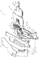
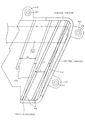
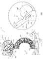
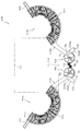
次いで、図5及び図6を参照して、動作ユニット300の詳細構成について説明する。図5は、動作ユニット300の正面斜視図であり、図6は、動作ユニット300の正面分解斜視図である。   Next, the detailed configuration of the operation unit 300 will be described with reference to FIGS. 5 and 6. FIG. 5 is a front perspective view of the operation unit 300, and FIG. 6 is a front exploded perspective view of the operation unit 300.

図5及び図6に示すように、動作ユニット300は、第1演出部材460をスライド移動させる第1ユニット400と、その第1ユニット400の側方(図5右側)に対向して配設されると共に第2演出部材560を回動させる第2ユニット500と、それら第1ユニット400及び第2ユニット500の背面側に配設されると共に一対の第3演出部材660を互いに近接離間する方向へ水平移動させる第3ユニット600と、その第3ユニット600の背面側に配設されると共に一対の第4演出部材760を互いに近接離間する方向に回動させる第4ユニット700と、を備える。   As shown in FIGS. 5 and 6, the operation unit 300 is disposed to face the first unit 400 that slides the first effect member 460 and the side of the first unit 400 (the right side in FIG. 5). And a second unit 500 that rotates the second effect member 560, and a pair of third effect members 660 that are disposed on the back side of the first unit 400 and the second unit 500 and that are close to and away from each other. A third unit 600 that is horizontally moved, and a fourth unit 700 that is disposed on the back side of the third unit 600 and rotates the pair of fourth effect members 760 in a direction to approach and separate from each other.

第4ユニット700は、一面側(図5及び図6紙面手前側)が開放された箱状の第4ケース710を備え、その第4ケース710の内部空間に、第1ユニット400、第2ユニット500及び第3ユニット600がそれぞれ収容される。   The fourth unit 700 includes a box-shaped fourth case 710 that is open on one side (the front side in FIGS. 5 and 6), and the first unit 400 and the second unit are disposed in the internal space of the fourth case 710. 500 and the third unit 600 are accommodated, respectively.

第4ユニット700の第4ケース710は、中央に矩形状の開口711aが開口形成されることで、正面視矩形の枠状に形成される。中央の開口711aは、第3図柄表示装置81(図2参照)の外形に対応した(即ち、表示内容を視認可能な)大きさの矩形状に形成される。一対の第4演出部材760は、開口711aの正面において互いの合わせ面同士を当接させる下降位置(図23参照)と、開口711aの形成領域外にそれぞれが退避する上昇位置(図5及び図6参照)との間で回動される。   The fourth case 710 of the fourth unit 700 is formed in a rectangular frame shape when viewed from the front by forming a rectangular opening 711a at the center. The central opening 711a is formed in a rectangular shape having a size corresponding to the outer shape of the third symbol display device 81 (see FIG. 2) (that is, the display content can be visually recognized). The pair of fourth effect members 760 has a lowered position (see FIG. 23) where the mating surfaces come into contact with each other in front of the opening 711a, and an elevated position where each of the fourth effect members 760 is retracted outside the formation region of the opening 711a (FIGS. 5 and 5). 6).

第3ユニット600は、その外形を形成する第3ケース610を備え、その第3ケース610に第3演出部材660などが収容(配設)される。第3ケース610は、第4ユニット700の第4ケース710の内形(壁部712の内壁面により形成される空間)と略同等の外形を有すると共に、中央に第4ケース710の開口711aの外形に対応した開口621が形成されることで、正面視矩形の枠状に形成される。第3ユニット600は、第3ケース610(第3ベース体620)の背面が第4ケース710の底面(底面板711の正面)と平行となる姿勢で第4ユニット700の内部空間に収納(配設)される。   The third unit 600 includes a third case 610 that forms its outer shape, and the third effect member 660 and the like are accommodated (arranged) in the third case 610. The third case 610 has an outer shape substantially the same as the inner shape of the fourth case 710 of the fourth unit 700 (the space formed by the inner wall surface of the wall portion 712), and the opening 711a of the fourth case 710 is formed at the center. By forming the opening 621 corresponding to the outer shape, it is formed in a rectangular frame shape when viewed from the front. The third unit 600 is stored (arranged) in the internal space of the fourth unit 700 in such a posture that the back surface of the third case 610 (third base body 620) is parallel to the bottom surface of the fourth case 710 (front surface of the bottom plate 711). Established).

第4ユニット700の第4ケース710には、複数の台座部711eが底面から立設され、それら各台座部711eに第3ユニット600の第3ケース610の外縁に形成される複数の被締結部624がそれぞれ締結固定されることで、第4ユニット700に第3ユニット600が配設(固定)される。即ち、第3ユニット600(第3ケース610)は、台座部711eの立設高さの分、第4ケース710の底面から嵩上げされた状態とされ、その嵩上げにより形成された空間(第4ケース710の底面(底面板711の正面)と第3ケース610の背面との間の対向面間)が、第4演出部材760が回転するための空間とされる。   In the fourth case 710 of the fourth unit 700, a plurality of pedestal portions 711e are erected from the bottom surface, and a plurality of fastened portions formed on the outer edges of the third case 610 of the third unit 600 on the pedestal portions 711e. The third unit 600 is disposed (fixed) in the fourth unit 700 by fastening and fixing the 624. That is, the third unit 600 (third case 610) is raised from the bottom surface of the fourth case 710 by the height of the pedestal portion 711e, and the space (fourth case) formed by the raising is provided. The bottom surface of 710 (the front surface of the bottom plate 711) and the opposite surface between the back surface of the third case 610 is a space for the fourth effect member 760 to rotate.

第1ユニット400及び第2ユニット500は、第3ユニット600の前面側(図5及び図6紙面手前側)であって、第4ユニット700の第4ケース710における一方(図5及び図6左側)の壁部712及び他方(図5及び図6右側)の壁部712に沿ってそれぞれ配設される。即ち、第1ユニット400及び第2ユニット500は、第3ケース610及び第4ケース710の開口621,711aを挟んだ左右に対向配置される。   The first unit 400 and the second unit 500 are the front side of the third unit 600 (the front side in FIG. 5 and FIG. 6), and one of the fourth units 710 in the fourth case 710 (the left side of FIGS. 5 and 6). ) And the other wall portion 712 (the right side in FIGS. 5 and 6). That is, the first unit 400 and the second unit 500 are opposed to each other on both sides of the openings 621 and 711a of the third case 610 and the fourth case 710.

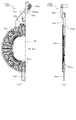
第1ユニット400は、図5に示すように、第1演出部材460が前面側(図5及び図6紙面手前側)に張り出して形成され、その第1演出部材460の先端側(先端部464)が、第2ユニット500の正面側に配置される。ここで、図7から図14を参照して、第1ユニット400について説明する。   As shown in FIG. 5, the first unit 400 is formed by projecting the first effect member 460 to the front side (the front side of FIG. 5 and FIG. 6), and the front end side (the tip portion 464) of the first effect member 460. Is disposed on the front side of the second unit 500. Here, the first unit 400 will be described with reference to FIGS. 7 to 14.

図7は、第1ユニット400の正面斜視図であり、図8は、第1ユニット400の正面分解斜視図である。なお、図7及び図8では、第1演出部材460が上昇位置に配置された状態が図示される。   FIG. 7 is a front perspective view of the first unit 400, and FIG. 8 is a front exploded perspective view of the first unit 400. 7 and 8 illustrate a state where the first effect member 460 is disposed at the raised position.

図7及び図8に示すように、第1ユニット400は、第1ケース410と、その第1ケース410に基端側がスライド移動可能に支持される第1演出部材460と、その第1演出部材460をスライド移動させるための駆動力を発生する第1駆動モータ470とを主に備える。   As shown in FIGS. 7 and 8, the first unit 400 includes a first case 410, a first effect member 460 that is slidably supported by the first case 410, and a first effect member thereof. And a first drive motor 470 that generates a driving force for sliding the 460.

第1ケース410は、一面側が開放された箱状の第1ベース体420と、その第1ベース体420の一面側に締結固定され第1ベース体420の開放部分を閉封する第1カバー体430と、その第1カバー体430の正面側に重ね合わされて締結固定される正面側部材440と、その正面側部材440の正面側に重ね合わされて締結固定される装飾連結板450とを備える。   The first case 410 includes a box-shaped first base body 420 that is open on one surface side, and a first cover body that is fastened and fixed to one surface side of the first base body 420 and closes an open portion of the first base body 420. 430, a front side member 440 that is overlapped and fastened to the front side of the first cover body 430, and a decorative connecting plate 450 that is overlapped and fastened to the front side of the front side member 440.

正面側部材440の内部(第1カバー体430の正面側との対向間)には、基板(図示せず)が収納され、その基板の正面側には、複数の発光手段(本実施形態では、LED)が全面にわたって点在配置される。正面側部材440及び装飾連結板450は、光透過性の樹脂材料から形成され、LEDの発光が正面側(図7及び図8紙面手前側)から視認可能とされる。なお、正面側部材440には、複数箇所に正面視矩形の開口が形成され、それら複数の開口においては、発光手段がそれぞれ露出されることで、発光手段が外部から直接視認可能とされる。   A substrate (not shown) is housed inside the front side member 440 (between the front side of the first cover body 430) and a plurality of light emitting means (in the present embodiment, on the front side of the substrate). , LEDs) are scattered over the entire surface. The front side member 440 and the decorative connecting plate 450 are formed from a light-transmitting resin material, and the light emission of the LED can be visually recognized from the front side (the front side of FIG. 7 and FIG. 8). Note that the front side member 440 is formed with a plurality of rectangular openings in a front view, and the light emitting means are exposed in each of the plurality of openings so that the light emitting means can be directly visually recognized from the outside.

正面側部材440は、第1カバー体430と正面視において略同一の外形に形成され、それらの外縁同士を一致させる位置で重ね合わされる一方、装飾連結板450は、正面側部材440よりも正面視において若干小さな外形に形成され、装飾連結板450の一部が正面側部材440の外縁から上方(図7及び図8上側)へ飛び出す(突出する)位置で重ね合わされる。   The front side member 440 is formed in substantially the same outer shape as the first cover body 430 in a front view, and is overlapped at a position where the outer edges thereof coincide with each other, while the decorative connecting plate 450 is more front than the front side member 440. It is formed in a slightly smaller outer shape in view, and a part of the decorative connecting plate 450 is overlapped at a position where it protrudes (protrudes) upward (upward in FIGS. 7 and 8) from the outer edge of the front side member 440.

装飾連結板450は、正面側部材440の外縁から上方(図7上側)へ飛び出す部分が、挿通孔451に挿通される締結ねじにより、第4ユニット700の第4ケース710の被締結孔712a(図23参照)に締結固定される。これにより、第4ユニット700の第4ケース710に第3ユニット600及び第1ユニット400が積み重ねられた状態で収容される場合であっても、全体としての剛性を確保して、各ユニット400,600の各演出部材460,660が動作する際のぐらつきを抑制できる。   A portion of the decorative connecting plate 450 that protrudes upward from the outer edge of the front-side member 440 (upper side in FIG. 7) is a fastening hole 712 a (in the fourth case 710 of the fourth unit 700) by a fastening screw that is inserted into the insertion hole 451. Fastened and fixed to (see FIG. 23). Accordingly, even when the third unit 600 and the first unit 400 are accommodated in the fourth case 710 of the fourth unit 700 in a stacked state, the overall rigidity is ensured, and each unit 400, It is possible to suppress wobbling when each of the 600 effect members 460 and 660 operates.

第1ベース体420及び第1カバー体430により形成される内部空間には、第1演出部材460の基端側(基部461)と、その第1演出部材460に駆動力を付与する第1駆動モータ470とが配設される。ここで、図9及び図10を参照して、第1ベース体420及び第1カバー体430の詳細構成について説明する。   In the internal space formed by the first base body 420 and the first cover body 430, the first end of the first effect member 460 (base 461) and the first drive that applies driving force to the first effect member 460. A motor 470 is disposed. Here, with reference to FIG.9 and FIG.10, the detailed structure of the 1st base body 420 and the 1st cover body 430 is demonstrated.

図9は、第1ベース体420及び第1カバー体430の正面分解斜視図である。図10(a)は、図9のXa−Xa線における第1ベース体420の部分拡大断面図であり、図10(b)は、図9のXb−Xb線における第1カバー体430の断面図である。なお、図9では、第1駆動モータ470及び駆動ギヤ472と、ピニオンギヤ480と、スライド位置検出センサSとが第1ベース体420に取着された状態が図示される。また、図10(a)では、理解を容易とするために、第1ベース体420が第3ユニット600の第3ケース610に積み重ねられる(図5参照)と共に第1演出部材460及びスライド位置検出センサSの電気的配線Sが配線された状態が図示される。   FIG. 9 is an exploded front perspective view of the first base body 420 and the first cover body 430. 10A is a partially enlarged cross-sectional view of the first base body 420 taken along line Xa-Xa in FIG. 9, and FIG. 10B is a cross-sectional view of the first cover body 430 taken along line Xb-Xb in FIG. FIG. 9 illustrates a state in which the first drive motor 470, the drive gear 472, the pinion gear 480, and the slide position detection sensor S are attached to the first base body 420. 10A, the first base body 420 is stacked on the third case 610 of the third unit 600 (see FIG. 5) and the first effect member 460 and the slide position detection are performed for easy understanding. The state where the electrical wiring S of the sensor S is wired is illustrated.

図9に示すように、第1ベース体420は、板状に形成され第1ベース体420の底面を形成する底面板421と、その底面板421から立設される壁部422と、その壁部422と同じ立設高さで底面板421から立設される案内壁423と、その案内壁423の延設方向と平行に延びる長円形状の孔として底面板421に開口形成される案内溝424とを備える。   As shown in FIG. 9, the first base body 420 includes a bottom plate 421 that is formed in a plate shape and forms the bottom surface of the first base body 420, a wall portion 422 that is erected from the bottom plate 421, and a wall thereof. Guide wall 423 erected from the bottom plate 421 at the same standing height as the portion 422, and a guide groove formed in the bottom plate 421 as an oval hole extending in parallel with the extending direction of the guide wall 423 424.

底面板421は、上底が下方(図9下側)となる姿勢の正面視台形形状に形成され、壁部422は、縦長の正面視平行四辺形形状に形成される。壁部422は、台形形状における2組の対辺のうちの長さが長くされる対辺に切り欠き部422a,422b,422cがそれぞれ凹設される。切り欠き部422aは、第1演出部材460の移動空間を確保するための切り欠きであり、第1演出部材460(基部461)の移動軌跡(図14参照)を含む領域に形成される。切り欠き部422b及び切り欠き部422cは、第1演出部材460及びスライド位置検出センサSの電気的配線Sを通過させる(取り回す)ための切り欠きである。   The bottom plate 421 is formed in a trapezoidal shape in a front view with an upper bottom downward (lower side in FIG. 9), and the wall portion 422 is formed in a vertically long parallelogram shape in a front view. The wall portion 422 is provided with notches 422a, 422b, and 422c on the opposite sides of the trapezoidal shape, the length of which is longer between the two pairs of opposite sides. The notch 422a is a notch for securing a moving space for the first effect member 460, and is formed in a region including the movement locus (see FIG. 14) of the first effect member 460 (base portion 461). The notch portion 422b and the notch portion 422c are notches for allowing the electrical wiring S of the first effect member 460 and the slide position detection sensor S to pass (manipulate).

案内壁423及び案内溝424は、第1演出部材460の移動を案内(一方向に規制)するための部位である。案内壁423は、壁部422の一部(図9右側部分)に対して所定間隔を隔てつつ平行に延設され、この壁部422の一部と案内壁423との対向間には、第1演出部材460のラック部465(図8参照)が配設される。案内溝424は、案内壁423と平行に延設され、第1演出部材460の基部461に取着されるカラーC(図8及び図12参照)が挿入される。   The guide wall 423 and the guide groove 424 are parts for guiding (restricting in one direction) the movement of the first effect member 460. The guide wall 423 extends in parallel to a part of the wall part 422 (the right side part in FIG. 9) with a predetermined interval, and between the part of the wall part 422 and the guide wall 423, The rack portion 465 (see FIG. 8) of the 1 effect member 460 is disposed. The guide groove 424 extends in parallel with the guide wall 423, and a collar C (see FIGS. 8 and 12) attached to the base 461 of the first effect member 460 is inserted.

底面板421は、案内壁423及び案内溝424の側方(図9右側)であって、これら両部423,424と壁部422(及び切り欠き部422a)との間に、スライド面421aを備える。スライド面421aは、第1演出部材460の基部461及びラック部465の底面をスライド移動可能に支持するための部位であり、ピニオンギヤ480の回転軸に垂直な平坦面として形成される。   The bottom plate 421 is on the side of the guide wall 423 and the guide groove 424 (right side in FIG. 9), and the slide surface 421a is formed between the both parts 423 and 424 and the wall part 422 (and the notch part 422a). Prepare. The slide surface 421a is a portion for supporting the bottom surface of the base portion 461 and the rack portion 465 of the first effect member 460 so as to be slidable, and is formed as a flat surface perpendicular to the rotation axis of the pinion gear 480.

なお、案内溝424には、その開口縁部に沿って壁部が正面側へ向けて立設され、案内溝424の内壁面の面積が拡大される。これにより、第1演出部材460のスライド移動を案内する際にカラーC(図11及び図12参照)から作用する面圧を小さくして、耐久性の向上を図ることができると共に、案内効果を確実として、第1演出部材460のスライド移動の高速化とを可能とすることができる。   Note that a wall portion is erected on the guide groove 424 toward the front side along the opening edge thereof, and the area of the inner wall surface of the guide groove 424 is enlarged. Thereby, when guiding the slide movement of the first effect member 460, the surface pressure acting from the collar C (see FIGS. 11 and 12) can be reduced to improve durability, and the guiding effect can be improved. As a certainty, it is possible to speed up the slide movement of the first effect member 460.

また、案内溝424の開口縁部に沿って立設される壁部は、壁部422及び案内壁423と同等の立設高さを有して形成される。よって、第1演出部材460が前後方向(図9紙面手前方向または奥方向)へ傾斜する場合やスライド移動の平面内へ傾斜する場合には、第1演出部材460に対し、その基部461のカラーCとラック465との両者を、案内溝424の開口縁部に沿って立設される壁部と壁部422又は案内壁423との両者によって同時に支えることができる。これにより、第1演出部材460の傾斜を抑制して、そのスライド移動の高速化を可能とすることができる。   Further, the wall portion erected along the opening edge portion of the guide groove 424 is formed to have a standing height equivalent to the wall portion 422 and the guide wall 423. Therefore, when the first effect member 460 is inclined in the front-rear direction (frontward or rearward direction in FIG. 9) or in the slide movement plane, the color of the base 461 with respect to the first effect member 460 is changed. Both C and the rack 465 can be supported simultaneously by both the wall portion erected along the opening edge of the guide groove 424 and the wall portion 422 or the guide wall 423. Thereby, the inclination of the 1st production member 460 can be suppressed and the speed of the slide movement can be increased.

壁部422の一部(図9右側)と案内壁423との対向間隔は、ラック部465の幅よりも若干大きくされ、壁部422又は案内壁423とラック部465との間に隙間が形成される。同様に、案内溝424の溝幅(内壁面の対向間隔)は、カラーC(本体部)の直径よりも若干大きくされ、案内溝424の内壁面とカラーC(本体部)の外周面との間に隙間が形成される。これにより、各部品の寸法公差を吸収して組み付け性の向上を図ることができるだけでなく、後述するように、第1演出部材460の移動が開始される際の初期動作をスムーズに(即ち、噛み込みを抑制)して、そのスライド移動の高速化を可能にすると共に、ラック部465(ラックギヤ465b)及びピニオンギヤ480における歯面の面圧を適正性化して、その歯面の磨耗を抑制できる。   The interval between the part of the wall part 422 (right side in FIG. 9) and the guide wall 423 is slightly larger than the width of the rack part 465, and a gap is formed between the wall part 422 or the guide wall 423 and the rack part 465. Is done. Similarly, the groove width (opposite distance between the inner wall surfaces) of the guide groove 424 is slightly larger than the diameter of the collar C (main body portion), and the inner wall surface of the guide groove 424 and the outer peripheral surface of the collar C (main body portion). A gap is formed between them. Thereby, not only can the dimensional tolerance of each part be absorbed to improve the assemblability, but the initial operation when the movement of the first effect member 460 is started smoothly (that is, as described later) (that is, It is possible to increase the speed of the sliding movement by suppressing the biting) and to optimize the tooth surface pressure in the rack portion 465 (rack gear 465b) and the pinion gear 480 to suppress the tooth surface wear. .

案内壁423及び案内溝424の間には、駆動ギヤ472と、その駆動ギヤ472に歯合されるピニオンギヤ480とが配設される。駆動ギヤ472は、第1駆動モータ470の駆動軸471に固着され、ピニオンギヤ480は、第1演出部材460のラック部465におけるラックギヤ465bに歯合可能な位置に配設される(図14参照)。   A drive gear 472 and a pinion gear 480 engaged with the drive gear 472 are disposed between the guide wall 423 and the guide groove 424. The drive gear 472 is fixed to the drive shaft 471 of the first drive motor 470, and the pinion gear 480 is disposed at a position that can mesh with the rack gear 465b in the rack portion 465 of the first effect member 460 (see FIG. 14). .

案内溝424の側方には、スライド位置検出センサSが配設される。スライド位置検出センサSは、発光部Sa及び受光部Sbを備えた光センサであり、それら発光部Sa及び受光部Sbの対向空間を、第1演出部材460の基部461における被検出板461b(図11参照)の移動軌跡上に配置することで、被検出板461bの有無に基づいて、第1演出部材460のスライド位置(上昇位置に位置するか否か)を検出する。   A slide position detection sensor S is disposed on the side of the guide groove 424. The slide position detection sensor S is an optical sensor including a light emitting unit Sa and a light receiving unit Sb, and a detected plate 461b in the base 461 of the first effect member 460 (see FIG. 11), the slide position of the first effect member 460 (whether or not it is located at the raised position) is detected based on the presence or absence of the detected plate 461b.

図9及び図10(b)に示すように、第1カバー体430は、正面視において第1ベース体420の壁部422の形成領域に対応する外形形状(即ち、縦長の平行四辺形形状)に形成され、その第1カバー体430の背面には、ラック案内凹部431と、カラー案内凹部432とが凹設される。   As shown in FIGS. 9 and 10B, the first cover body 430 has an outer shape corresponding to the formation region of the wall portion 422 of the first base body 420 in front view (that is, a vertically long parallelogram shape). A rack guide recess 431 and a collar guide recess 432 are provided in the back of the first cover body 430.

ラック案内凹部431及びカラー案内凹部432は、第1演出部材460の移動を案内(一方向に規制)するために直線状に延設される凹部であり、ラック案内凹部431には第1演出部材460のラック部465における案内リブ465c(図11参照)が、カラー案内凹部432には第1演出部材460の基部461におけるカラーC(本体部、図11参照)が、それぞれ挿入される。   The rack guide recessed portion 431 and the collar guide recessed portion 432 are recessed portions that extend linearly in order to guide (restrict in one direction) the movement of the first effect member 460, and the rack guide recess 431 includes the first effect member. The guide rib 465c (see FIG. 11) in the rack portion 465 of 460 is inserted, and the collar C (main body portion, see FIG. 11) in the base portion 461 of the first effect member 460 is inserted into the collar guide recess 432, respectively.

第1カバー体430が第1ベース体420に締結固定された組立状態において、ラック案内凹部431は、第1ベース体420のスライド面421aに対面して(即ち、ラック部465の案内リブ465cの移動軌跡に沿って)、カラー案内凹部432は、第1ベース体420の案内溝424に対面して、それぞれ形成される。   In the assembled state in which the first cover body 430 is fastened and fixed to the first base body 420, the rack guide recess 431 faces the slide surface 421a of the first base body 420 (that is, the guide rib 465c of the rack section 465). The color guide recesses 432 are formed to face the guide grooves 424 of the first base body 420, respectively, along the movement trajectory.

第1カバー体430のラック案内凹部431及びカラー案内凹部432と、第1ベース体420の案内壁423及び案内溝424とによる案内効果により、第1演出部材460の移動方向が一方向(ラック案内凹部431及びカラー案内凹部432と案内壁423及び案内溝424との延設方向)に規制される(図14参照)。   Due to the guiding effect of the rack guide recess 431 and collar guide recess 432 of the first cover body 430 and the guide wall 423 and guide groove 424 of the first base body 420, the moving direction of the first effect member 460 is one direction (rack guide). The extending direction of the recess 431 and the collar guide recess 432, the guide wall 423, and the guide groove 424) is regulated (see FIG. 14).

なお、第1カバー体430の厚み寸法(図10(b)上下方向寸法)は、図10(b)に示すように、ラック案内凹部431の形成領域の厚み寸法が、他の領域(カラー案内凹部431を挟んでラック案内凹部431と反対側となる領域、図10(b)左側)の厚み寸法に比較して大きく(厚く)される。本実施形態では、第1カバー体430の外縁(図10(b)右端)からカラー案内溝432の開口縁部(第1演出部材460(図8参照)に近い側の開口縁部)に沿った仮想直線までの領域において、厚み寸法が大きくされる。   As shown in FIG. 10B, the thickness dimension of the first cover body 430 (the vertical dimension in FIG. 10B) is the same as the other area (color guide). It is larger (thicker) than the thickness dimension of the region opposite to the rack guide recess 431 across the recess 431, that is, the left side of FIG. In the present embodiment, from the outer edge of the first cover body 430 (the right end in FIG. 10B) to the opening edge of the collar guide groove 432 (the opening edge on the side close to the first effect member 460 (see FIG. 8)). In the region up to the imaginary straight line, the thickness dimension is increased.

このように、ラック案内凹部431の形成領域を含む範囲の厚み寸法のみを大きくすることで、第1カバー体430において、第1演出部材460から作用する荷重が大きい領域の厚み寸法のみを部分的に大きくすることができる。これにより、第1カバー体430の耐久性の向上を図りつつ、第1カバー体430全体の厚み寸法が不必要に大きくなることを抑制して、軽量化と材料コストの削減とを図ることができる。   In this way, by increasing only the thickness dimension in the range including the formation area of the rack guide recess 431, only the thickness dimension of the area where the load acting from the first effect member 460 is large is partially applied to the first cover body 430. Can be large. Thereby, while aiming at the improvement of durability of the 1st cover body 430, it can suppress that the thickness dimension of the 1st cover body 430 whole becomes unnecessarily large, and aim at weight reduction and reduction of material cost. it can.

また、このように、カラー案内凹部432に比較して溝幅(図10(b)左右方向寸法)が小さくされるラック案内凹部431の形成領域において、第1カバー体430の厚み寸法が大きくされることで、カラー案内凹部432のように第1カバー体430の正面(図10(b)上側面)に突出させずに、ラック案内凹部431を凹設できるので、第1カバー体430全体としての肉厚を均一化して、樹脂金型による射出成形時の成形性の向上を図ることができる。   In addition, the thickness dimension of the first cover body 430 is increased in the formation region of the rack guide recess 431 in which the groove width (dimension in the left-right direction in FIG. 10B) is made smaller than the collar guide recess 432 as described above. Thus, the rack guide recess 431 can be provided without protruding from the front surface (upper side surface of FIG. 10B) of the first cover body 430 like the color guide recess 432, so that the first cover body 430 as a whole is provided. It is possible to make the wall thickness uniform and improve the moldability at the time of injection molding with a resin mold.

カラー案内凹部432には、その開口縁部に沿って壁部が立設され、カラー案内凹部432の内壁面の面積が拡大される。壁部の立設先端は、上述のように厚み寸法が大きくされる部分と面一とされる。これにより、第1演出部材460のスライド移動を案内する際にカラーC(図11及び図12参照)から作用する面圧を小さくして、耐久性の向上を図ることができると共に、案内効果を確実として、第1演出部材460のスライド移動の高速化とを可能とすることができる。   A wall portion is erected along the opening edge of the color guide recess 432, and the area of the inner wall surface of the color guide recess 432 is increased. The standing tip of the wall portion is flush with the portion where the thickness dimension is increased as described above. Thereby, when guiding the slide movement of the first effect member 460, the surface pressure acting from the collar C (see FIGS. 11 and 12) can be reduced to improve durability, and the guiding effect can be improved. As a certainty, it is possible to speed up the slide movement of the first effect member 460.

また、上述した第1ベース体420の場合と同様に、ラック案内凹部431の溝幅(内壁面の対向間隔、図10(b)左右方向寸法)は、ラック部465の案内リブ465c(図11参照)の厚み寸法よりも大きな寸法に設定され、カラー案内凹部432の溝幅(内壁面の対向間隔、図10(b)左右方向寸法)はカラーC(本体部)の直径よりも大きな寸法(即ち、案内溝424の溝幅と同等の寸法)に設定される。これにより、各部品の寸法公差を吸収して組み付け性の向上を図ることができるだけでなく、後述するように、第1演出部材460の移動が開始される際の初期動作をスムーズに(即ち、噛み込みを抑制)して、そのスライド移動の高速化を可能にすると共に、ラック部465(ラックギヤ465b)及びピニオンギヤ480における歯面の面圧を適正性化して、その歯面の磨耗を抑制できる。   Similarly to the case of the first base body 420 described above, the groove width of the rack guide recess 431 (the interval between the opposing inner wall surfaces, FIG. 10B, the horizontal dimension) is the guide rib 465c of the rack portion 465 (FIG. 11). The thickness of the collar guide recess 432 is larger than the diameter of the collar C (main body) (see FIG. 10B). That is, it is set to a dimension equivalent to the groove width of the guide groove 424. Thereby, not only can the dimensional tolerance of each part be absorbed to improve the assemblability, but the initial operation when the movement of the first effect member 460 is started smoothly (that is, as described later) (that is, It is possible to increase the speed of the sliding movement by suppressing the biting) and to optimize the tooth surface pressure in the rack portion 465 (rack gear 465b) and the pinion gear 480 to suppress the tooth surface wear. .

第1ベース体420の底面板421には、壁部422により囲まれた領域の外方となる部分に複数の被締結部425と爪部426と受入孔427とが形成される。被締結部425は、第3ケース体630の台座部635(図21参照)に締結固定される部位であり、締結ねじが挿通される挿通孔が穿設される。各被締結部425に挿通された締結ねじが、第3ユニット600における第3ケース体630の台座部635にそれぞれ締結されることで、第1ケース410(第1ユニット400)が第3ケース610(第3ユニット600)に積み重ねられた状態で配設される(図36参照)。   The bottom plate 421 of the first base body 420 is formed with a plurality of fastened portions 425, claw portions 426, and receiving holes 427 in portions that are outside the region surrounded by the wall portion 422. The fastened portion 425 is a portion fastened and fixed to the pedestal portion 635 (see FIG. 21) of the third case body 630, and an insertion hole through which a fastening screw is inserted is formed. The fastening screws inserted through the respective fastened portions 425 are fastened to the pedestal portions 635 of the third case body 630 in the third unit 600, so that the first case 410 (first unit 400) becomes the third case 610. The third unit 600 is disposed in a stacked state (see FIG. 36).

爪部426は、電気的配線Sを保持するための爪状の部位であり、底面板421から立設される基部と、その基部の立設先端から底面板421と水平に延設される延設部と、その延設部の延設先端を底面板421へ向けて屈曲させて形成される屈曲部とからなる。屈曲部の屈曲先端と底面板421との間には、電気的配線Sを通過させるのに必要な隙間が確保される。   The claw portion 426 is a claw-shaped portion for holding the electrical wiring S, and has a base portion standing from the bottom surface plate 421 and an extension extending horizontally from the bottom end plate of the base portion to the bottom surface plate 421. And a bent portion formed by bending the extended tip of the extended portion toward the bottom plate 421. A gap necessary to pass the electrical wiring S is secured between the bent tip of the bent portion and the bottom plate 421.

受入孔427は、底面板421に貫通形成される孔であり、爪部426の延設部および屈曲部に対面する位置であって、かつ、第3ケース610の第3ベース体620及び第3カバー体630を締結固定する締結ボルトBの頭部に対応する位置に配設される。即ち、第1ケース410(第1ベース体420)を第3ケース610(第3カバー体630)の正面に積み重ねる場合には(図5及び図6参照)、第3ケース610における第3カバー体630の正面から突出される締結ボルトBの頭部を、第1ベース体420の受入孔427に受け入れる(挿入する)ことができる。よって、締結ボルトBの頭部が突出されていても、第1ベース体420の背面を第3カバー体630の正面に密着させることができる。これにより、第1ケース410及び第3ケース610を厚み方向に嵩張らせることなく積み重ねることができ、全体としての厚み寸法(図10(a)上下方向寸法)を低減することができる。   The receiving hole 427 is a hole penetratingly formed in the bottom plate 421, a position facing the extended portion and the bent portion of the claw portion 426, and the third base body 620 and the third portion of the third case 610. The cover body 630 is disposed at a position corresponding to the head of the fastening bolt B that fastens and fixes the cover body 630. That is, when the first case 410 (first base body 420) is stacked on the front surface of the third case 610 (third cover body 630) (see FIGS. 5 and 6), the third cover body in the third case 610 is provided. The head of the fastening bolt B protruding from the front surface of 630 can be received (inserted) into the receiving hole 427 of the first base body 420. Therefore, even if the head of the fastening bolt B is protruded, the back surface of the first base body 420 can be brought into close contact with the front surface of the third cover body 630. Thereby, the 1st case 410 and the 3rd case 610 can be piled up without making it bulky in the thickness direction, and the thickness dimension (Drawing 10 (a) up-and-down direction dimension) as a whole can be reduced.

この場合、受入孔427は爪部426に対面する位置に形成されるので、受入孔427の開口を爪部426により塞ぐ(隠す)ことができる。これにより、締結ボルトBの頭部が受入孔427の開口を介して外部に露出されることを抑制して、かかる締結ボルトBの頭部への外部からのアクセス(頭部を操作すること)を困難とすることができる。更に、爪部426は電気的配線Sを保持する部位であるため、かかる電気的配線Sによっても受入孔427の開口を塞ぐ(隠す)ことができる。   In this case, since the receiving hole 427 is formed at a position facing the claw portion 426, the opening of the receiving hole 427 can be closed (hidden) by the claw portion 426. Accordingly, the head of the fastening bolt B is prevented from being exposed to the outside through the opening of the receiving hole 427, and the access to the head of the fastening bolt B from the outside (manipulating the head). Can be difficult. Furthermore, since the claw portion 426 is a part that holds the electrical wiring S, the opening of the receiving hole 427 can be blocked (hidden) by the electrical wiring S as well.

特に、電気的配線Sは、爪部426の延設方向に直交する方向(図10(a)紙面垂直方向)に沿って配線されるので、爪部426によって塞ぐ(隠す)ことが困難な爪部426の両側(図9上側および下側)の空間を電気的配線Sによって効果的に塞ぐことができる。即ち、受入孔427を爪部426に対面する位置に形成することで、締結ボルトBの頭部に外部からアクセスし難く(頭部を操作し難く)することを、爪部426及び電気的配線Sによって相乗的に高めることができる。   In particular, since the electrical wiring S is wired along the direction orthogonal to the extending direction of the claw portion 426 (FIG. 10A, the direction perpendicular to the paper surface), it is difficult to close (hide) the claw portion 426. The space on both sides (the upper side and the lower side in FIG. 9) of the portion 426 can be effectively blocked by the electrical wiring S. That is, by forming the receiving hole 427 at a position facing the claw portion 426, it is difficult to access the head of the fastening bolt B from the outside (it is difficult to operate the head). S can be synergistically enhanced.

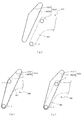
図7及び図8に戻って説明する。第1ケース410(第1ベース体420及び第1カバー体430)には、第1演出部材460がスライド移動可能に配設される。第1演出部材460は、基端側が第1ベース体420及び第1カバー体430に支持されると共に、先端側が第1ケース410(第1ベース体420及び第1カバー体430)の側方から水平に張り出された姿勢で配設される。ここで、図11から図13を参照して、第1演出部材460の詳細構成について説明する。   Returning to FIG. 7 and FIG. The first effect member 460 is slidably disposed in the first case 410 (the first base body 420 and the first cover body 430). The first effect member 460 is supported by the first base body 420 and the first cover body 430 at the base end side, and from the side of the first case 410 (the first base body 420 and the first cover body 430) at the distal end side. It is arranged in a horizontally projecting posture. Here, the detailed configuration of the first effect member 460 will be described with reference to FIGS. 11 to 13.

図11は、第1演出部材460の正面分解斜視図である。図12(a)は、第1演出部材460の正面図であり、図12(b)は、図12(a)の矢印XIIb方向視における第1演出部材460の側面図である。図13(a)は、第1演出部材460の背面図であり、図13(b)及び図13(c)は、図13(a)のXIIIb部における第1演出部材460の部分拡大背面図である。なお、図12(a)、図12(b)、図13(a)及び図13(b)では、ラック部465が基部461に取着された状態が図示される一方、図13(c)では、ラック部465が基部461から取り外された状態が図示される。   FIG. 11 is a front exploded perspective view of the first effect member 460. 12 (a) is a front view of the first effect member 460, and FIG. 12 (b) is a side view of the first effect member 460 as viewed in the direction of the arrow XIIb in FIG. 12 (a). Fig.13 (a) is a rear view of the 1st effect member 460, FIG.13 (b) and FIG.13 (c) are the partial expanded rear views of the 1st effect member 460 in the XIIIb part of Fig.13 (a). It is. 12 (a), 12 (b), 13 (a), and 13 (b) illustrate a state in which the rack portion 465 is attached to the base portion 461, while FIG. 13 (c). In the figure, a state in which the rack portion 465 is removed from the base portion 461 is illustrated.

図11から図13に示すように、第1演出部材460は、基部461と、その基部461の側方(図12(a)及び図12(b)右側)縁部から正面(図12(b)上側)へ向けて立設される立設部462と、その立設部462の立設先端から基部461と水平に延設される延設部463と、その延設部463の延設先端に配設される先端部464と、基部461の上方(図12(a)上側)縁部に連結されるラック部465と、を備える。   As shown in FIGS. 11 to 13, the first effect member 460 has a base 461 and a side (right side of FIGS. 12A and 12B) of the base 461 from the front (FIG. 12B). ) Standing portion 462 erected toward the upper side), an extending portion 463 extending horizontally from the base 461 from the standing tip of the standing portion 462, and an extending tip of the extension portion 463 And a rack portion 465 connected to an upper (upper side in FIG. 12A) edge of the base portion 461.

基部461は、樹脂材料から正面視くの字の平板状に形成され(図12(a)参照)、第1ベース体420及び第1カバー体430にスライド移動可能に支持される。この基部461には、カラーCを軸支する支持軸461aと、スライド位置検出センサSにより検出される部位である被検出板461bとが一体に形成される。   The base portion 461 is formed from a resin material into a plate shape in a front view (see FIG. 12A), and is supported by the first base body 420 and the first cover body 430 so as to be slidable. The base 461 is integrally formed with a support shaft 461 a that supports the collar C and a detected plate 461 b that is a part detected by the slide position detection sensor S.

支持軸461aは、円柱状に形成される部位であり、基部461の正面から一対一組が立設されると共に、その正面と反対側となる基部461の背面から一対一組が立設される。正面の組は、背面の組に対して、同軸となる位置に配置される。支持軸461aがカラーCの中央に貫通形成される軸支孔に挿通されることで、カラーCが基部461に回転可能に軸支される。   The support shaft 461a is a part formed in a columnar shape, and one pair is erected from the front of the base 461, and one pair is erected from the back of the base 461 opposite to the front. . The front set is disposed at a position that is coaxial with the back set. The support shaft 461a is inserted into a shaft support hole formed in the center of the collar C so that the collar C is rotatably supported by the base portion 461.

なお、カラーCの各組は、基部461の側方縁部であって立設部462が形成される側と反対側となる側方(図12(a)左側)縁部に沿って配設される。より詳細には、各組の一方の支持軸461aは、正面視くの字に形成される基部461の一端(図12(a)左下側)に位置し、他方の支持軸461aは、正面視くの字に形成される基部461の屈曲部(図12(a)左上側)に位置する。   Each set of the collars C is disposed along the side edge (left side in FIG. 12A) which is the side edge of the base 461 and opposite to the side where the standing portion 462 is formed. Is done. More specifically, one support shaft 461a of each set is located at one end (lower left side in FIG. 12 (a)) of a base portion 461 formed in a square shape in front view, and the other support shaft 461a is in front view. It is located at a bent portion (upper left side of FIG. 12A) of the base portion 461 formed in a square shape.

カラーCは、軸支孔を有する円筒状の本体部と、その本体部の軸方向端部における外周面から径方向外方へ向けて張り出すフランジ状のフランジ部とが樹脂材料から一体に形成されてなり、フランジ部を基部461の正面または背面へ向けた姿勢で支持軸461aに取着される。即ち、カラーCは、フランジ部の直径が第1ベース体420の案内溝424及び第1カバー体430のカラー案内凹部432(図9及び図10(b)参照)の溝幅よりも大きくされ、本体部が案内溝424及びカラー案内凹部432に変位可能に挿通されると共にその本体部の外周面が案内溝424及びカラー案内凹部432の内壁面により案内される。   In the collar C, a cylindrical main body portion having a shaft support hole and a flange-like flange portion projecting radially outward from an outer peripheral surface at an axial end portion of the main body portion are integrally formed from a resin material. Thus, the flange portion is attached to the support shaft 461a in a posture in which the flange portion is directed to the front surface or the back surface of the base portion 461. That is, in the collar C, the diameter of the flange portion is made larger than the groove width of the guide groove 424 of the first base body 420 and the collar guide recess 432 of the first cover body 430 (see FIGS. 9 and 10B). The main body is inserted into the guide groove 424 and the collar guide recess 432 so as to be displaceable, and the outer peripheral surface of the main body is guided by the inner walls of the guide groove 424 and the collar guide recess 432.

本実施形態では、基部461の背面(図12(b)下側面)から立設される支持軸461aには締結ねじが締結固定され、その締結ねじの頭部の直径は、カラーC(本体部)の挿通孔の直径よりも大きくされる。よって、基部461の背面の支持軸461aに装着されるカラーCは、軸方向への移動が規制される(即ち、カラーCが締結ねじの頭部により保持される)。一方、基部461の正面(図12(b)上側面)から立設される支持軸461aに装着されるカラーCは締結ねじによる締結固定が省略され、支持軸461aから抜取り可能な状態とされる。   In the present embodiment, a fastening screw is fastened and fixed to a support shaft 461a that is erected from the back surface of the base portion 461 (the lower side surface in FIG. 12B). ) Is made larger than the diameter of the insertion hole. Therefore, the movement of the collar C attached to the support shaft 461a on the back surface of the base portion 461 in the axial direction is restricted (that is, the collar C is held by the head of the fastening screw). On the other hand, the collar C attached to the support shaft 461a erected from the front of the base portion 461 (upper side surface in FIG. 12B) is not fastened by fastening screws, and can be removed from the support shaft 461a. .

これにより、正面側の締結ねじを省略することで、その分、部品点数を少なくして、部品コストの低減を図ることができる。このように、部品コストの低減を図るべく、締結ねじを省略した場合でも、本実施形態では、組立作業性の悪化を回避することができる。   Thereby, by omitting the fastening screw on the front side, the number of parts can be reduced correspondingly, and the part cost can be reduced. Thus, even when the fastening screw is omitted in order to reduce the component cost, in this embodiment, it is possible to avoid the deterioration of the assembly workability.

即ち、第1ユニット400の組立は、第1ベース体430の開放された一面側(図9紙面手前側)に第1演出部材460の基部461をその正面側(図9紙面手前側)を上方とした姿勢(即ち、正面側のカラーCが支持軸461aから脱落しない姿勢)で載置し、第1カバー体420を被せた後、締結固定することで行われる。よって、基部461の背面側のカラーCは、支持軸461aからの脱落を防止するべく、締結ねじにより保持しておく必要がある一方で、基部461の正面側のカラーCは、組立工程中、常に上方に位置するので、支持軸461aからの脱落を防止する必要がない。また、基部461の正面側のカラーCは、第1カバー体430が被せられれば、カラー案内凹部432により保持されるので、この点からも、支持軸461aからの脱落を締結ねじにより防止する必要がない。このように、正面側の支持軸461aへの締結ねじの締結を省略しても、組立作業性の悪化を回避できる。   That is, the first unit 400 is assembled by placing the base 461 of the first effect member 460 on the open side of the first base body 430 (front side of FIG. 9) and the front side (front side of FIG. 9) upward. This is performed by placing the first cover body 420 and then fastening and fixing it in the posture described above (that is, the posture where the collar C on the front side does not fall off the support shaft 461a). Therefore, the collar C on the back side of the base portion 461 needs to be held by a fastening screw to prevent the collar 461 from falling off from the support shaft 461a, while the collar C on the front side of the base portion 461 is held during the assembly process. Since it is always positioned above, it is not necessary to prevent the support shaft 461a from falling off. Further, since the collar C on the front side of the base portion 461 is held by the collar guide recess 432 when the first cover body 430 is covered, it is necessary to prevent the falling off from the support shaft 461a with a fastening screw also from this point. There is no. Thus, even if the fastening of the fastening screw to the support shaft 461a on the front side is omitted, deterioration in assembly workability can be avoided.

基部461は、図13(c)に示すように、ラック軸支座面461cと、そのラック軸支座面461cの中央から立設される円柱状のラック支持軸461dと、そのラック支持軸461dの周囲に立設されるラック規制壁461eとを備える。ラック軸支座面461cは、ラック部465の本体465aの基端側を支持する部位であり、平坦面として形成される。   As shown in FIG. 13C, the base 461 includes a rack shaft support surface 461c, a columnar rack support shaft 461d erected from the center of the rack shaft support surface 461c, and the rack support shaft 461d. And a rack restriction wall 461e that stands up around the door. The rack shaft support surface 461c is a portion that supports the base end side of the main body 465a of the rack portion 465, and is formed as a flat surface.

ラック支持軸461dは、ラック465(本体465a)を回転可能に軸支するための断面円形の軸であり、ラック部465の本体465aに貫通形成される断面円形の軸支孔465dに挿通される。ラック支持軸461dの外径は、軸支孔465dの内径よりも小さな寸法に設定される。よって、ラック支持軸461dには、若干のがたつきを有した状態で、ラック部465(本体465a)が回転可能に軸支される。   The rack support shaft 461d is a shaft with a circular cross section for rotatably supporting the rack 465 (main body 465a), and is inserted into a shaft support hole 465d with a circular cross section formed through the main body 465a of the rack portion 465. . The outer diameter of the rack support shaft 461d is set to be smaller than the inner diameter of the shaft support hole 465d. Therefore, the rack portion 465 (main body 465a) is rotatably supported on the rack support shaft 461d with a slight backlash.

ラック規制壁461eは、ラック部465がラック支持軸461dを中心として回転する際にその回転を所定の回転角度内に規制するための部位であり、図13(c)に示す背面視において、ラック支持軸461dを中心とする半円形状に形成される半円部と、その半円部の両端から互いに平行な直線状に延設される直線部とを備える。即ち、ラック規制壁461eは、背面視において、長円形状の一部を切り取った形状に形成される。またラック規制壁461eの直線部は、一対一組のカラーCの軸心を結ぶ方向と平行に延設される。   The rack regulating wall 461e is a part for regulating the rotation within a predetermined rotation angle when the rack portion 465 rotates about the rack support shaft 461d. In the rear view shown in FIG. A semicircular portion formed in a semicircular shape centering on the support shaft 461d and a linear portion extending in a straight line parallel to each other from both ends of the semicircular portion are provided. That is, the rack regulating wall 461e is formed in a shape obtained by cutting out a part of an oval shape in the rear view. The straight portion of the rack regulating wall 461e extends in parallel with the direction connecting the axes of the pair of collars C.

ラック規制壁461eの半円部の内径r1は、ラック部465の本体465aにおける基端側(図13(c)下側)の外径r2よりも大きくされ(r2<r1)、かつ、ラック規制壁461eの直線部の対向間隔w1は、ラック部465の本体465aにおける基端側の幅寸法w2よりも大きくされる(w2<w1)。なお、対向間隔w1は内径r1の2倍とされ(w1=2×r1)、幅寸法w2は外径r2の2倍とされる(w2=2×r2)。   The inner diameter r1 of the semicircular portion of the rack regulating wall 461e is made larger than the outer diameter r2 (r2 <r1) on the base end side (lower side in FIG. 13C) of the main body 465a of the rack portion 465, and the rack regulating wall The facing interval w1 between the straight portions of the wall 461e is made larger than the width dimension w2 on the base end side of the main body 465a of the rack portion 465 (w2 <w1). The facing interval w1 is twice the inner diameter r1 (w1 = 2 × r1), and the width dimension w2 is twice the outer diameter r2 (w2 = 2 × r2).

ラック部465は、対向間隔w1と幅寸法w2との寸法差の分だけ、ラック支持軸461dを中心として所定量の回転が可能とされる。また、ラック支持軸461dの外径(半径)と軸支孔465dの内径(半径)との寸法差は、内径r1と外径r2との寸法差(r1−r2)と同等または若干大きくされる。これにより、ラック部465は、基部461に対して、ラック軸支座面461cの面内で所定量の水平移動が可能とされる。この場合、ラック部465の回転または水平移動が所定量を超えると、ラック規制壁461eの内周壁によりラック部465(本体465a)の側面を受け止めて、それ以上の回転または水平移動を規制できる。即ち、回転または水平移動による荷重を、ラック支持軸461d及び軸支孔465dのみで負担するのではなく、ラック規制壁461eにも分散させることができるので、その分、耐久性の向上を図ることができる。   The rack portion 465 can be rotated by a predetermined amount around the rack support shaft 461d by the dimensional difference between the facing interval w1 and the width dimension w2. The dimensional difference between the outer diameter (radius) of the rack support shaft 461d and the inner diameter (radius) of the shaft support hole 465d is equal to or slightly larger than the dimensional difference (r1-r2) between the inner diameter r1 and the outer diameter r2. . As a result, the rack portion 465 can be moved horizontally by a predetermined amount in the plane of the rack shaft support surface 461c with respect to the base portion 461. In this case, if the rotation or horizontal movement of the rack portion 465 exceeds a predetermined amount, the side surface of the rack portion 465 (main body 465a) is received by the inner peripheral wall of the rack restriction wall 461e, and further rotation or horizontal movement can be restricted. In other words, the load due to rotation or horizontal movement can be distributed not only to the rack support shaft 461d and the shaft support hole 465d but also to the rack regulating wall 461e, so that the durability is improved accordingly. Can do.

なお、ラック規制壁461eのラック軸支座面461cからの立設高さ(図13(c)紙面垂直方向寸法)は、ラック部465の本体465aにおける基端側(図13(c)下側)の厚み寸法(図13(c)紙面垂直方向寸法)よりも若干大きくされる。よって、第1演出部材460が第1ベース体420に装着され(図8参照)、ラック規制壁461eの立設先端面が第1ベース体420のスライド面421a(図9参照)に当接されると、ラック部465は、その基端側が、スライド面421aとラック軸支座面461cとの間で回転可能に保持される。   The height of the rack regulating wall 461e from the rack shaft support surface 461c (FIG. 13 (c), the vertical dimension in the drawing) is the base end side of the main body 465a of the rack portion 465 (the lower side in FIG. 13 (c)). ) Thickness dimension (FIG. 13 (c) dimension in the direction perpendicular to the paper surface). Therefore, the first effect member 460 is mounted on the first base body 420 (see FIG. 8), and the standing front end surface of the rack regulating wall 461e is brought into contact with the slide surface 421a (see FIG. 9) of the first base body 420. Then, the base end side of the rack portion 465 is held so as to be rotatable between the slide surface 421a and the rack shaft support surface 461c.

立設部462は、延設部463の配設位置を基部461よりも正面側(図12(b)上側)に嵩上げするために、基部461の側方(図12(a)上右側)縁部に一体に形成される部位であり、基部461の側方縁部から正面側(図12(b)上側)へ向けて立設される立設部分462aと、その立設部分462aの立設先端から基部461と反対側(図12(b)右側)へ向けて基部461と水平に延設される平板状の平板部分462bとを備える。   The standing portion 462 has a side edge (upper right side in FIG. 12A) of the base portion 461 in order to raise the arrangement position of the extending portion 463 to the front side (upper side in FIG. 12B) than the base portion 461. And a standing part 462a standing from the side edge of the base 461 toward the front side (upper side in FIG. 12B), and the standing part 462a. A base 461 and a flat plate portion 462b extending horizontally are provided from the tip toward the side opposite to the base 461 (right side in FIG. 12B).

立設部分462aは、基部461に平行な仮想平面で切断した断面形状が、延設部463側(図12(a)右側)が開放されるコの字状に形成され、軽量化が図られつつ、基部461に対し延設部463が傾斜する方向(図12(b)上下方向)への曲げ剛性の向上が図られている。平板部分462aは、延設部463の基端側(図12(b)左側)の背面に締結固定される。   The standing portion 462a has a cross-sectional shape cut along an imaginary plane parallel to the base portion 461, and is formed in a U-shape in which the extending portion 463 side (the right side in FIG. 12A) is opened, thereby reducing the weight. However, the bending rigidity is improved in the direction in which the extending portion 463 is inclined with respect to the base portion 461 (the vertical direction in FIG. 12B). The flat plate portion 462a is fastened and fixed to the back surface of the extending portion 463 on the base end side (left side in FIG. 12B).

延設部463は、第1演出部材460の構成要素の中で最大の外形および重量を有する部位であり、中空の箱状に形成される。縁設部463の内部には、発光手段(例えば、LED)及び回路基板(いずれも図示せず)が収容される。延設部463は、図12(a)に示すように、一対一組のカラーCのうちのラック465側(図12(a)上側)に位置するカラーCと立設部462とを結ぶ方向(図12(a)左右方向)に沿って延設される。よって、延設部463は、正面視(図12(a))において、一対一組のカラーC(支持軸461a)を結ぶ方向に対して、傾斜する方向に沿って延設される。   The extending portion 463 is a portion having the largest outer shape and weight among the components of the first effect member 460, and is formed in a hollow box shape. Inside the edge portion 463, a light emitting means (for example, LED) and a circuit board (both not shown) are accommodated. As shown in FIG. 12A, the extending portion 463 connects the collar C positioned on the rack 465 side (upper side in FIG. 12A) of the pair of collars C and the standing portion 462. (Fig. 12 (a) left and right direction). Therefore, the extending portion 463 extends along a direction inclined with respect to a direction connecting the pair of collars C (support shafts 461a) in a front view (FIG. 12A).

延設部463の正面には、装飾板463aが配設される。装飾板463aは、所定の文字列(例えば、パチンコ機10の名称を示す文字列)が形成される部材であり、正面側の一部分(本実施形態では、文字列の各文字に対応する形状部分)が光透過性材料から形成される。遊技者は、延設部463の光透過性材料からなる部分を介して、その内部に配設される発光手段(例えば、LED)の発光が視認可能とされる。   A decorative plate 463a is disposed in front of the extending portion 463. The decorative plate 463a is a member on which a predetermined character string (for example, a character string indicating the name of the pachinko machine 10) is formed, and a part on the front side (in this embodiment, a shape portion corresponding to each character of the character string) ) Is formed from a light transmissive material. The player can visually recognize the light emission of the light emitting means (for example, LED) disposed in the extension portion 463 through the portion made of the light transmissive material.

先端部464は、第1演出部材460の先端側に形成されると共に、第2ユニット500によって重力方向下方から支持される部位であり(図19(a)参照)、延設部463の先端側(図12(b)右側)の背面に締結固定される取着部分464aと、その取着部分464aから外方へ向けて張り出すと共に正面視横長の平板形状に形成される先端板部分464bとを備える。   The front end portion 464 is a portion that is formed on the front end side of the first effect member 460 and that is supported by the second unit 500 from below in the gravity direction (see FIG. 19A), and is on the front end side of the extending portion 463. An attachment portion 464a fastened and fixed to the back surface of FIG. 12 (b) right side, and a tip plate portion 464b that protrudes outward from the attachment portion 464a and is formed in a horizontally long flat plate shape when viewed from the front. Is provided.

先端板部分464bは、図12(a)に示す正面視において、一対一組のカラーCのうちのラック465側(図12(a)上側)に位置するカラーCと立設部462とを結ぶ方向(即ち、延設部463の延設方向、図12(a)左右方向)に平行に延設される。   The front end plate portion 464b connects the collar C located on the rack 465 side (upper side in FIG. 12A) of the pair of collars C and the standing portion 462 in the front view shown in FIG. It extends in parallel to the direction (that is, the extending direction of the extending portion 463, the left-right direction in FIG. 12A).

また、先端板部分464bは、図12(b)に示す側面視において、基端部461と平行となる姿勢で配設されると共に、基端部461よりも延設部463側(前面側)へ距離N1だけオフセットした位置(即ち、正面側へ嵩上げされた位置)に配設される。これにより、先端部464の耐久性の向上を図ることができる。   Further, the distal end plate portion 464b is disposed in a posture parallel to the base end portion 461 in the side view shown in FIG. 12B, and extends from the base end portion 461 side (front side). It is disposed at a position offset by a distance N1 (that is, a position raised to the front side). Thereby, the durability of the tip 464 can be improved.

即ち、第1演出部材460は、基部461に対して延設部463が前面側(図12(b)上側)に張り出した形状であるため、図12(b)に示す側面視における第1演出部材460全体としての重心位置は、図12(b)に位置Gとして図示するように、基部461を含む平面よりも延設部463側に位置し(本実施形態では、延設部463の背面(図12(b)下側)近傍に位置する)、第1演出部材460がスライド移動する際に(或いは、第1演出部材460が停止中であっても)延設部463の上下方向(図12(b)紙面垂直方向)への揺れ(図12(a)に示す正面視において延設部463が図12(a)上下方向へ変位する揺れ。即ち、基部461及び先端部464を固定端とし延設部463を自由端とする自由振動)が発生しやすい。先端板部分464bは、後述するように、第2ユニット500の各規制リブ532,542や支持壁533,543(いずれも図19参照)により支持される部位であるため、延設部463の上下方向への揺れが発生すると、その揺れ(即ち、延設部463部分の重量)を先端部464により支える必要があり、かかる先端部464の耐久性が懸念される。   That is, since the first effect member 460 has a shape in which the extending part 463 projects to the front side (upper side in FIG. 12B) with respect to the base 461, the first effect in the side view shown in FIG. The position of the center of gravity of the member 460 as a whole is located closer to the extended portion 463 than the plane including the base portion 461 as illustrated as a position G in FIG. 12B (in this embodiment, the back surface of the extended portion 463). When the first effect member 460 slides (or even when the first effect member 460 is stopped) (in the vicinity of the lower side in FIG. 12B), the vertical direction of the extending portion 463 ( 12B (swing direction perpendicular to the paper surface) (swing in which the extended portion 463 is displaced in the vertical direction in FIG. 12A in the front view shown in FIG. 12A), that is, the base 461 and the tip 464 are fixed. Free vibration with the extension 463 as the free end) Easy to. As will be described later, the distal end plate portion 464b is a portion supported by the regulating ribs 532 and 542 and the support walls 533 and 543 (both see FIG. 19) of the second unit 500. When the swaying in the direction occurs, it is necessary to support the swaying (that is, the weight of the extending portion 463) by the tip portion 464, and there is a concern about the durability of the tip portion 464.

この場合、本実施形態では、先端板部分464bが、基端部461よりも延設部463側へ距離N1だけオフセットされるので、距離N1のオフセットがされない場合と比較して、重心位置(位置G)と先端板部分464bとの間の距離を小さくすることができる。これにより、延設部463の上下方向(図12(b)紙面垂直方向)への揺れ(先端部464を固定端とし延設部463を自由端とする自由振動)が発生した場合でも、その揺れ(延設部463部分の重量)により先端板部分464bに作用するモーメントを小さくして、先端部464の耐久性の向上を図ることができる。また、このように、重心位置と先端板部分464bとの間の距離が小さくされることで、延設部463の上下方向への揺れを早期に収束させることができる。   In this case, in the present embodiment, the distal end plate portion 464b is offset by the distance N1 from the base end portion 461 toward the extending portion 463, so that the center of gravity position (position) is compared with the case where the offset of the distance N1 is not performed. The distance between G) and the tip plate portion 464b can be reduced. As a result, even when the extending portion 463 swings in the vertical direction (the vertical direction in FIG. 12B) (free vibration with the distal end portion 464 as a fixed end and the extending portion 463 as a free end), The moment acting on the tip plate portion 464b due to shaking (weight of the extended portion 463 portion) can be reduced, and the durability of the tip portion 464 can be improved. In addition, as described above, the distance between the center of gravity position and the tip plate portion 464b is reduced, so that the swinging of the extending portion 463 in the vertical direction can be converged at an early stage.

先端板部分464bの正面(図12(a)紙面手前側面)には、その外縁に沿って壁部が立設され、先端板部部分464bの剛性の向上が図られている。先端板部分464bの正面に立設される壁部の立設先端面および先端板部材464bの背面は、基部461に平行な平坦面として形成される。また、先端板部分464bの嵩上げ位置(図12上下方向位置)は、図12(b)に示すように、基端部461の正面と延設部463の背面との間に設定される。   On the front surface (front side surface in FIG. 12A) of the front end plate portion 464b, a wall portion is erected along the outer edge so as to improve the rigidity of the front end plate portion 464b. The standing front end surface of the wall portion standing on the front surface of the front end plate portion 464b and the back surface of the front end plate member 464b are formed as flat surfaces parallel to the base portion 461. Further, the raised position (vertical direction position in FIG. 12) of the distal end plate portion 464b is set between the front surface of the base end portion 461 and the back surface of the extending portion 463, as shown in FIG.

ラック部465は、第1ベース体420に配設されるピニオンギヤ480と組み合わされてラック・アンド・ピニオンを構成する部位であり、第1駆動モータ470の回転力を第1演出部材460の直線の動き(スライド移動)に変換する。ラック部465は、長尺板状の本体465aと、その本体465aの側面に刻設されピニオンギヤ480に歯合されるラックギヤ465bと、本体465aの正面(図11紙面手前側面)に立設される2本の案内リブ465cと、本体465aの基端側に貫通形成される軸支孔465dと、を備える。   The rack portion 465 is a part that forms a rack and pinion in combination with the pinion gear 480 disposed on the first base body 420, and the rotational force of the first drive motor 470 is applied to the straight line of the first effect member 460. Convert to movement (slide movement). The rack portion 465 is erected on a long plate-like main body 465a, a rack gear 465b engraved on a side surface of the main body 465a and meshed with the pinion gear 480, and a front surface of the main body 465a (front side surface in FIG. 11). Two guide ribs 465c and a shaft support hole 465d formed through the base end side of the main body 465a are provided.

本体465aの基端側(図13(a)下側)は、軸支孔465dを中心とする半円形状に形成される。2本の案内リブ465cは、本体465aの長手方向に沿って互いに平行に延設され、第1ベース体420にラック部465が取着され第1カバー体430が被せられると(図7参照)、その第1カバー体430のラック案内凹部431(図10(b)参照)に挿通される。   The base end side (the lower side in FIG. 13A) of the main body 465a is formed in a semicircular shape centering on the shaft support hole 465d. The two guide ribs 465c extend in parallel with each other along the longitudinal direction of the main body 465a, and when the rack portion 465 is attached to the first base body 420 and the first cover body 430 is covered (see FIG. 7). The first cover body 430 is inserted into the rack guide recess 431 (see FIG. 10B).

案内リブ465cの立設高さ(図12(a)紙面垂直方向寸法)は、第1カバー体430のラック案内凹部431の凹設深さ(図10(b)上下方向寸法)よりも大きくされる。これにより、第1演出部材460の前面側への変位(揺れ)に伴い、ラック部465が第1カバー体430側(前面側、図8紙面手前側)へ変位される場合には、案内リブ465cの突設先端のみをラック案内凹部431の底面(図10(b)上側面)に当接させることができ、ラック部465の本体465aの前面(図12(a)紙面手前側面)が第1カバー体430の背面(図10(b)下側面)に当接して、当接面積が過大となることを抑制できる。   The standing height of the guide rib 465c (FIG. 12 (a) vertical dimension in the drawing) is made larger than the depth of the rack guide recess 431 of the first cover body 430 (FIG. 10 (b) vertical dimension). The Accordingly, when the rack portion 465 is displaced to the first cover body 430 side (front side, front side in FIG. 8) in accordance with the displacement (swing) of the first effect member 460 to the front side, the guide ribs are provided. Only the projecting tip of 465c can be brought into contact with the bottom surface (upper side surface of FIG. 10B) of the rack guide recess 431, and the front surface of the main body 465a of the rack portion 465 (front side surface in FIG. 12A) is first. It is possible to prevent the contact area from being excessively increased by contacting the back surface of the one cover body 430 (the lower surface in FIG. 10B).

これにより、第1演出部材460のスライド移動中に前面側の変位(揺れ)が発生した場合であっても、摺動抵抗を小さくして、第1演出部材460のスライド移動の高速化を可能とできる。特に、本実施形態では、上述したように、第1演出部材460の重心位置(位置G)が基部461及びラック部465よりも前面側(図12(b)上側)に位置するため、第1演出部材460が前面側に変位しやすい(揺れやすい)ため、ラック部465の前面側に案内リブ465cを設ける構成が有効となる。   Thereby, even when a displacement (swing) on the front side occurs during the slide movement of the first effect member 460, the sliding resistance can be reduced and the slide movement of the first effect member 460 can be speeded up. And can. In particular, in the present embodiment, as described above, the position of the center of gravity (position G) of the first effect member 460 is located on the front side (upper side in FIG. 12B) than the base portion 461 and the rack portion 465. Since the effect member 460 is easily displaced to the front side (easy to shake), the configuration in which the guide ribs 465c are provided on the front side of the rack portion 465 is effective.

ラック部465は、軸支孔465dに基部461のラック支持軸461dが挿通された状態で、基部461に取着される。この取着状態では、ラック部465は、その本体部465aの長手方向が、一対一組のカラーC(支持軸461a)を結ぶ方向と平行となる姿勢で配設されると共に、一対一組のカラーC(支持軸461a)を結ぶ仮想直線よりも延設部463側へ距離N2だけオフセットされた位置に配設される。なお、ラック部465は、この平行とされる位置を中央位置として、上述したように、左右(図13(b)左右方向)へ所定量だけ回転可能とされる(図13(b)参照)。   The rack portion 465 is attached to the base portion 461 in a state where the rack support shaft 461d of the base portion 461 is inserted into the shaft support hole 465d. In this attached state, the rack portion 465 is disposed in a posture in which the longitudinal direction of the main body portion 465a is parallel to the direction connecting the pair of collars C (support shafts 461a), and the pair of pairs. It is disposed at a position offset from the virtual straight line connecting the collar C (support shaft 461a) by the distance N2 toward the extending portion 463. The rack portion 465 can be rotated by a predetermined amount left and right (FIG. 13B, left and right direction) with the parallel position as the center position as described above (see FIG. 13B). .

ここで、ラック部465が基部461に対して所定量だけ回転可能に連結されることで、第1ユニット400の組立作業性の向上を図ることができる。即ち、第1演出部材460を第1ベース体420に装着する際には、基部461の背面側に配設される一対一組のカラーCを第1ベース体420に形成される案内溝424に挿通させる工程と、ラック部465のラックギヤ465bを第1ベース体420に配設されるピニオンギヤ480に歯合させる工程との2つの工程を行う必要がある。これら両工程は、寸法公差に起因する位置ずれだけでなく、ピニオンギヤ480及びラックギヤ465bの位相ずれも考慮する必要があるため、同時に両工程を行うことが困難である。   Here, since the rack portion 465 is rotatably connected to the base portion 461 by a predetermined amount, the assembly workability of the first unit 400 can be improved. That is, when the first effect member 460 is attached to the first base body 420, a pair of collars C disposed on the back side of the base 461 is formed in the guide groove 424 formed in the first base body 420. It is necessary to perform two processes: a process of inserting the rack gear 465b of the rack portion 465 and a process of engaging the pinion gear 480 provided in the first base body 420. In both of these processes, it is necessary to consider not only the positional deviation caused by the dimensional tolerance but also the phase deviation of the pinion gear 480 and the rack gear 465b, so that it is difficult to carry out both processes simultaneously.

これに対し、本実施形態では、ラック部465が基部461に対して所定量だけ回転可能に連結されるので、その回転の分、基部461に配設されるカラーCとラック部465に形成されるラックギヤ465bとの位置関係の自由度を高めることができる。これにより、基部461の背面側に配設される一対一組のカラーCを第1ベース体420に配設される案内溝424へ挿通させる工程と、ラックギヤ465bをピニオンギヤ480に歯合させる工程とを同時に或いは順に行いやすくすることができる。その結果、組立作業性の向上を図ることができる。   On the other hand, in the present embodiment, the rack portion 465 is rotatably connected to the base portion 461 by a predetermined amount, so that the rotation is formed on the collar C and the rack portion 465 disposed on the base portion 461. The degree of freedom of the positional relationship with the rack gear 465b can be increased. Thus, a step of inserting a pair of collars C disposed on the back side of the base portion 461 into the guide groove 424 disposed on the first base body 420, and a step of engaging the rack gear 465b with the pinion gear 480. Can be performed simultaneously or sequentially. As a result, it is possible to improve the assembly workability.

なお、第1ベース体420への第1演出部材460の装着は、上述のように、基部461にラック部465が連結された状態で行う必要はなく、本実施形態では、次のように行うこともできる。即ち、まず、ラック部465を、そのラックギヤ465bをピニオンギヤ480に歯合させつつ、第1ベース体420のスライド面421aに載置し、次いで、基部461を、その背面側のカラーCを案内溝424に挿通させつつ、スライド面421aに載置し、その載置の際にラック部465の軸支孔465dへ基部461のラック支持軸461dを挿通させることで、第1ベース体420へ第1演出部材460を装着しても良い。これによれば、ラックギヤ465bとピニオンギヤ480との歯合、カラーCの案内溝424への挿通、及び、ラック支持軸461dの軸支孔465dへの挿通を、それぞれ1工程ずつ順に行うことができるので、その組立作業性の向上を図ることができる。   Note that the mounting of the first effect member 460 to the first base body 420 does not have to be performed in a state where the rack portion 465 is coupled to the base portion 461 as described above, and is performed as follows in the present embodiment. You can also. That is, first, the rack portion 465 is placed on the slide surface 421a of the first base body 420 while the rack gear 465b is engaged with the pinion gear 480, and then the base portion 461 and the collar C on the back side thereof are guided through the guide groove. The first base body 420 is inserted into the first base body 420 by inserting the rack support shaft 461d of the base portion 461 into the shaft support hole 465d of the rack portion 465 at the time of placement. An effect member 460 may be attached. According to this, the engagement between the rack gear 465b and the pinion gear 480, the insertion of the collar C into the guide groove 424, and the insertion of the rack support shaft 461d into the shaft support hole 465d can be sequentially performed one step at a time. Therefore, the assembly workability can be improved.

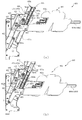
次いで、図14を参照して、第1ユニット400における第1演出部材460のスライド移動について説明する。図14(a)は、第1演出部材460が上昇位置に配置された状態における第1ユニット400の正面図であり、図14(b)は、第1演出部材460が下降位置に配置された状態における第1ユニット400の正面図である。なお、図14では、理解を容易とするために、第1ベース体420から第1カバー体430が取り外された状態が図示される。   Next, referring to FIG. 14, the sliding movement of the first effect member 460 in the first unit 400 will be described. FIG. 14A is a front view of the first unit 400 in a state in which the first effect member 460 is disposed in the raised position, and FIG. 14B is a diagram in which the first effect member 460 is disposed in the lowered position. It is a front view of the 1st unit 400 in a state. FIG. 14 shows a state where the first cover body 430 is removed from the first base body 420 for easy understanding.

図14(a)に示すように、第1演出部材460が上昇位置に配置された状態では、基部461(カラーCの一方)及びラック部465が、第1ベース体420の案内溝424及びスライド面421aの上端(図14(a)上側)にそれぞれ位置される。また、上昇位置では、基部461の被検出板461bが、スライド位置検出センサSの発光部Sa及び受光部Sb(図9参照)の対向空間に配置され、第1演出部材460が上昇位置に位置することが検出可能とされる。   As shown in FIG. 14A, in the state where the first effect member 460 is disposed at the raised position, the base 461 (one of the collars C) and the rack portion 465 are connected to the guide groove 424 and the slide of the first base body 420. It is located at the upper end (upper side in FIG. 14A) of the surface 421a. Further, at the raised position, the detected plate 461b of the base 461 is disposed in the space between the light emitting part Sa and the light receiving part Sb (see FIG. 9) of the slide position detection sensor S, and the first effect member 460 is located at the raised position. It is possible to detect.

この上昇位置に配置された状態から、第1駆動モータ470が正方向に回転駆動され、ピニオンギヤ480が図14(a)時計まわりに回転されると、そのピニオンギヤ480の回転がラックギヤ465bに伝達されることで、ラック部465が案内壁423及びラック案内凹部431(図10(b)参照)の延設方向に沿って下方(図14(a)左斜め下側)へスライド移動される。同時に、ラック部465のスライド移動に伴い、基部461がカラーCを介して案内溝424及びラック案内凹部432(図10(b)参照)に案内されその案内溝424及びラック案内凹部432の延設方向に沿って下方(ラック部465の移動方向と平行な方向)へスライド移動される。   When the first drive motor 470 is driven to rotate in the forward direction from the state where it is disposed at this raised position, and the pinion gear 480 is rotated clockwise in FIG. 14A, the rotation of the pinion gear 480 is transmitted to the rack gear 465b. As a result, the rack portion 465 is slid downward (slantingly downward on the left side in FIG. 14A) along the extending direction of the guide wall 423 and the rack guide recess 431 (see FIG. 10B). At the same time, as the rack portion 465 slides, the base portion 461 is guided to the guide groove 424 and the rack guide recess 432 (see FIG. 10B) via the collar C, and the guide groove 424 and the rack guide recess 432 are extended. It is slid along the direction downward (a direction parallel to the moving direction of the rack portion 465).

この場合、第1駆動モータ470の回転数が所定の回転数までカウントされると、第1演出部材460が下降位置に到達したと判断され、第1駆動モータ470の回転駆動が停止される。その結果、図14(b)に示すように、第1演出部材460が下降位置に配置される。   In this case, when the rotation speed of the first drive motor 470 is counted up to a predetermined rotation speed, it is determined that the first effect member 460 has reached the lowered position, and the rotation drive of the first drive motor 470 is stopped. As a result, as shown in FIG. 14B, the first effect member 460 is disposed at the lowered position.

図14(b)に示すように、第1演出部材460が下降位置に配置された状態では、ラック部465の長手方向一端側(図14(b)上側)が壁部422及び案内壁423の対向間に位置されると共に、案内リブ465cがラック案内凹部431に挿入されており、それら壁部422及び案内壁423とラック案内凹部431とによる案内効果が継続される。   As shown in FIG. 14B, in the state where the first effect member 460 is disposed at the lowered position, one end in the longitudinal direction of the rack portion 465 (the upper side in FIG. 14B) is the wall portion 422 and the guide wall 423. The guide rib 465c is inserted into the rack guide concave portion 431 while being positioned between the facing portions, and the guide effect by the wall portion 422, the guide wall 423, and the rack guide concave portion 431 is continued.

一方、図14(b)に示すように、下降位置に配置された状態から、第1駆動モータ470が逆方向に回転駆動され、ピニオンギヤ480が図14(b)反時計まわりに回転されると、そのピニオンギヤ480の回転がラックギヤ465bに伝達されることで、ラック部465が案内壁423及びラック案内凹部431(図10(b)参照)の延設方向に沿って上方(図14(b)右斜め上側)へスライド移動される。同時に、ラック部465のスライド移動に伴い、基部461がカラーCを介して案内溝424及びラック案内凹部432(図10(b)参照)に案内されその案内溝424の延設方向に沿って上方(ラック部465の移動方向と平行な方向)へスライド移動される。   On the other hand, as shown in FIG. 14B, when the first drive motor 470 is driven to rotate in the reverse direction from the state where it is disposed in the lowered position, the pinion gear 480 is rotated counterclockwise in FIG. 14B. The rotation of the pinion gear 480 is transmitted to the rack gear 465b, so that the rack portion 465 moves upward along the extending direction of the guide wall 423 and the rack guide recess 431 (see FIG. 10B) (FIG. 14B). It is slid to the upper right). At the same time, as the rack portion 465 slides, the base portion 461 is guided to the guide groove 424 and the rack guide concave portion 432 (see FIG. 10B) via the collar C and is moved upward along the extending direction of the guide groove 424. It is slid and moved in the direction parallel to the moving direction of the rack portion 465.

この場合、上述したように、基部461の被検出板461bが、スライド位置検出センサSにより検出されることで、第1演出部材460が上昇位置に到達したと判断され、第1駆動モータ470の回転駆動が停止される。その結果、図14(a)に示すように、第1演出部材460が上昇位置に配置される。なお、この上昇位置および下降位置の間の動作過程においては、ラック部465の案内リブ465cがラック案内凹部431により案内される状態が継続(維持)される。   In this case, as described above, the detected plate 461b of the base 461 is detected by the slide position detection sensor S, so that it is determined that the first effect member 460 has reached the raised position, and the first drive motor 470 The rotational drive is stopped. As a result, as shown in FIG. 14A, the first effect member 460 is disposed at the raised position. In the operation process between the raised position and the lowered position, the state in which the guide rib 465c of the rack portion 465 is guided by the rack guide recess 431 is continued (maintained).

第1演出部材460は、上述したように、基部461が正面視くの字状に形成され、延設部463が、第1演出部材460の構成要素の中で最大の外形および重量を有する部位であるところ、延設部463は、一対一組のカラーCのうちの正面視くの字形状に形成される基部461の屈曲部(図14(a)上側、ラック部465側)に位置するカラーCと正面視くの字形状に形成される基部461の他端(図14(a)上右側、立設部462(図12参照))とを結ぶ方向(図14(a)左右方向)に沿って延設され、ラック部465は、カラーCと延設部463との間となる位置において上方(図14(a)右上側)へ向けて延設される。   As described above, the first effect member 460 is formed such that the base portion 461 is shaped like a square when viewed from the front, and the extended portion 463 has the largest outer shape and weight among the components of the first effect member 460. However, the extended portion 463 is located at a bent portion (upper side in FIG. 14A, the rack portion 465 side) of the base portion 461 formed in a square shape in front view of the pair of collars C. The direction (FIG. 14A left-right direction) that connects the collar C and the other end of the base 461 formed in a U-shape when viewed from the front (upper right side in FIG. 14A, upright portion 462 (see FIG. 12)). The rack portion 465 extends upward (upper right side in FIG. 14A) at a position between the collar C and the extending portion 463.

そのため、延設部463の重量を、上記屈曲部に位置するカラーC(図14(a)上側)を中心として、第1演出部材460全体が図14(a)時計まわりに回転される方向へ作用させることができる。即ち、延設部463の重量を、ラック部465のラックギヤ465bをピニオンギヤ480から離間させる方向(図14(a)右側)へ作用させることができる。   Therefore, the weight of the extending portion 463 is set so that the entire first effect member 460 is rotated clockwise in FIG. 14 (a) around the collar C (upper side in FIG. 14 (a)) located at the bent portion. Can act. In other words, the weight of the extending portion 463 can be applied in the direction in which the rack gear 465b of the rack portion 465 is separated from the pinion gear 480 (right side in FIG. 14A).

これにより、ラックギヤ465bとピニオンギヤ480との間の歯面の面圧が過大となることを回避して、ラック・アンド・ピニオンを円滑に動作させることができるので、第1演出部材460をスムーズにスライド移動させ、そのスライド移動の高速化とを可能とすることができる。また、ラックギヤ465b及びピニオンギヤ480の歯の磨耗を抑制することができる。   As a result, the surface pressure of the tooth surface between the rack gear 465b and the pinion gear 480 can be avoided and the rack and pinion can be operated smoothly, so that the first effect member 460 can be smoothly moved. It is possible to move the slide and increase the speed of the slide movement. Further, wear of teeth of the rack gear 465b and the pinion gear 480 can be suppressed.

ここで、図14(a)又は図14(b)に示す上昇位置または下降位置に停止された状態から第1演出部材460のスライド移動を開始する場合は、摺動面における静摩擦および慣性力の影響が大きく、また、歯の歯合状態の影響を受けやすいため、第1演出部材460をスライド移動させ始める際の初期動作をスムーズに行わせることが困難となり、その結果、第1駆動モータ470の負荷が大きくなる。   Here, when the sliding movement of the first effect member 460 is started from the state where it is stopped at the ascending position or the descending position shown in FIG. 14 (a) or FIG. 14 (b), the static friction and the inertial force on the sliding surface are reduced. Since the influence is large and it is easy to be affected by the meshing state of the teeth, it is difficult to smoothly perform the initial operation when starting to slide the first effect member 460. As a result, the first drive motor 470 The load of increases.

これに対し、本実施形態の第1演出部材460は、上述したように、基部461に対して、ラック部465が変位可能(即ち、がたつきを有して)に軸支されるので(図13(c)参照)、そのがたつきの分、第1駆動モータ470(ピニオンギヤ480)の回転駆動によりラック部465がスライド移動され始める際には、ラック部465及び基部461のそれぞれを適正な位置に相対的に変位させる(なじませる)ことができる。即ち、ピニオンギヤ480に対してラック部465(ラックギヤb)自体が抵抗のより少ない位置に変位できると共に、ラック部465に対して基部461も独立して抵抗がより少ない位置に変位できる。これにより、初期動作をスムーズに行わせることができ、その分、第1駆動モータ470の負担を軽減することができる。   On the other hand, as described above, the first effect member 460 of the present embodiment is pivotally supported so that the rack portion 465 can be displaced (that is, has rattling) with respect to the base portion 461 ( 13 (c)), when the rack portion 465 starts to slide by the rotational drive of the first drive motor 470 (pinion gear 480), each of the rack portion 465 and the base portion 461 is properly moved. It can be displaced relative to the position. That is, the rack portion 465 (rack gear b) itself can be displaced to a position with less resistance with respect to the pinion gear 480, and the base portion 461 can be independently displaced to a position with less resistance with respect to the rack portion 465. Thereby, the initial operation can be performed smoothly, and the burden on the first drive motor 470 can be reduced accordingly.

また、基部461及びラック部465が、がたつきを有して軸支されていることで(図13参照)、そのがたつきの分、第1演出部材460の演出部463(装飾板463a)を振動させつつ(揺れさせつつ)、スライド移動させることができるので、その振動により演出効果を高めることができる。   In addition, the base portion 461 and the rack portion 465 are pivotally supported with a backlash (see FIG. 13), and the effect portion 463 (decoration plate 463a) of the first effect member 460 is equivalent to the backlash. Can be slid while being vibrated (vibrated), so that the production effect can be enhanced by the vibration.

特に、後述するように、第1演出部材460の先端部464は、定常状態では、支持壁533,543の直線部分533a,543aにより重力方向下方から支持され(図19参照)、重力方向上方(図14上方向)への変位が許容されると共に、背面規制リブ532及び正面規制リブ542との間には隙間が形成され(図19参照)、前後方向(図14紙面垂直方向)への変位が許容されるので、スライド移動時の演出部463の振動を形成しやすくできる。   In particular, as will be described later, the distal end portion 464 of the first effect member 460 is supported from below in the gravitational direction by the straight portions 533a and 543a of the support walls 533 and 543 in a steady state (see FIG. 19), and above the gravitational direction ( Displacement in the upward direction in FIG. 14 is allowed, and a gap is formed between the rear surface regulation rib 532 and the front surface regulation rib 542 (see FIG. 19), and displacement in the front-rear direction (perpendicular direction in FIG. 14). Therefore, it is possible to easily form the vibration of the effect part 463 during the slide movement.

更に、基部461及びラック部465が別体とされ、かつ、それら両部材461,465の軸支部分にがたつきを有することで(図13参照)、第1ベース体420に第1演出部材460を組み付ける際には、がたつきの分、寸法公差を吸収することができる。よって、第1ベース体420へ第1演出部材460を組み付ける際の組み付け性の向上を図ることができる。また、がたつきの分、各部品に要求される寸法公差を緩やかとすることができるので、部品コストを削減することができる。   Further, the base portion 461 and the rack portion 465 are separated from each other, and the shaft support portions of both the members 461 and 465 have a backlash (see FIG. 13), so that the first effect member is added to the first base body 420. When assembling 460, the dimensional tolerance can be absorbed by the backlash. Therefore, it is possible to improve the assemblability when the first effect member 460 is assembled to the first base body 420. In addition, since the dimensional tolerance required for each part can be moderated by the amount of rattling, the part cost can be reduced.

即ち、第1演出部材460を第1ベース体420に装着する際には、基部461の背面側に配設される一対一組のカラーCを第1ベース体420に形成される案内溝424に挿通させると共に、ラック部465のラックギヤ465bを第1ベース体420に配設されるピニオンギヤ480に歯合させる必要がある。この場合に、基部461とラック部465とが相対変位不能に固着されていれると、一対一組のカラーCを先に案内溝424にそれぞれ挿通させると、ラックギヤ465bとピニオンギヤ480との歯合が困難となり、一方、ラックギヤ465bとピニオンギヤ480との歯合を先に行うと、一対一組のカラーCのいずれか一方の案内溝424への挿通が困難になる事態が発生する。   That is, when the first effect member 460 is attached to the first base body 420, a pair of collars C disposed on the back side of the base 461 is formed in the guide groove 424 formed in the first base body 420. The rack gear 465b of the rack portion 465 needs to be engaged with the pinion gear 480 disposed on the first base body 420 while being inserted. In this case, if the base portion 461 and the rack portion 465 are fixed so as not to be relatively displaceable, when the pair of collars C is first inserted into the guide grooves 424, the meshing between the rack gear 465b and the pinion gear 480 is performed. On the other hand, if the rack gear 465b and the pinion gear 480 are first meshed, it may be difficult to insert one of the collars C into one of the guide grooves 424.

これに対し、本実施形態では、ラック部465が基部461に対して所定量だけ変位可能に(即ち、がたつきを有して)連結されるので、その分、基部461に配設されるカラーCとラック部465に形成されるラックギヤ465bとの位置関係の自由度を高めることができる。これにより、一対一組のカラーCを先に案内溝424へ挿通させたとしても、その状態からラックギヤ465bをピニオンギヤ480に対して位置調整することができるので、これら両ギヤ465b,480を容易に歯合させることができる。一方、ラックギヤ465bとピニオンギヤ480との歯合を先に行ったとしても、その状態から基部461を案内溝424に対して位置調整することができるので、一対一組のカラーCのそれぞれを案内溝424へ容易に挿通することができる。   On the other hand, in the present embodiment, the rack portion 465 is connected to the base portion 461 so as to be displaceable by a predetermined amount (that is, with backlash), and accordingly, the rack portion 465 is disposed on the base portion 461 accordingly. The degree of freedom of the positional relationship between the collar C and the rack gear 465b formed in the rack portion 465 can be increased. As a result, even if the pair of collars C is inserted into the guide groove 424 first, the position of the rack gear 465b with respect to the pinion gear 480 can be adjusted from that state, so that both the gears 465b and 480 can be easily adjusted. Can be engaged. On the other hand, even if the engagement between the rack gear 465b and the pinion gear 480 is performed first, the position of the base portion 461 can be adjusted with respect to the guide groove 424 from that state, so that each of the pair of collars C is guided to the guide groove. 424 can be easily inserted.

また、本実施形態によれば、ラック部465が基部461に対して所定量だけ変位可能に(即ち、がたつきを有して)連結されることで、第1ベース体420に第1演出部材460を組み付けた後、その第1ベース体420に第1カバー体430を組み付ける工程においても、基部461の正面側に配設される一対一組のカラーCを第1カバー体430のカラー案内凹部432に挿通する工程およびラック部465の案内リブ465cを第1カバー体430のラック案内凹部431に挿通する工程を共に容易に行うことができる。   In addition, according to the present embodiment, the rack portion 465 is connected to the base portion 461 so as to be displaceable by a predetermined amount (that is, with backlash), whereby the first effect is added to the first base body 420. In the step of assembling the first cover body 430 to the first base body 420 after assembling the member 460, the pair of collars C arranged on the front side of the base portion 461 is used as the color guide for the first cover body 430. Both the step of inserting the recess 432 and the step of inserting the guide rib 465c of the rack portion 465 into the rack guide recess 431 of the first cover body 430 can be easily performed.

次いで、図15から図20を参照して、第2ユニット500について説明する。図15は、第2ユニット500の正面斜視図である。なお、図15では、図面を簡素化して、理解を容易とするために、第2カバー体530及び支持部材540の正面側に形成される装飾形状の図示が省略される。   Next, the second unit 500 will be described with reference to FIGS. 15 to 20. FIG. 15 is a front perspective view of the second unit 500. In FIG. 15, in order to simplify the drawing and facilitate understanding, illustration of a decorative shape formed on the front side of the second cover body 530 and the support member 540 is omitted.

図15に示すように、第2ユニット500は、第2ケース510と、その第2ケース510に基端側が回転可能に軸支される第2演出部材560と、その第2演出部材560を回転させるための駆動力を発生する駆動手段(図示せず)とを主に備える。   As shown in FIG. 15, the second unit 500 rotates the second case 510, the second effect member 560 that is pivotally supported by the second case 510 so that the base end side is rotatable, and the second effect member 560. Driving means (not shown) for generating a driving force for the purpose.

第2ケース510は、一面側が開放された箱状の第2ベース体520と、その第2ベース体520の一面側に締結固定され第2ベース体520の開放部分を閉封する第2カバー体530と、その第2カバー体530の上方における正面側に重ね合わされて締結固定される支持部材540と、第2カバー体530の下方における正面側に重ね合わされて締結固定される装飾部材550と、を備える。   The second case 510 includes a box-shaped second base body 520 that is open on one surface side, and a second cover body that is fastened and fixed to one surface side of the second base body 520 and closes an open portion of the second base body 520. 530, a support member 540 that is overlapped and fastened to the front side above the second cover body 530, and a decorative member 550 that is overlapped and fastened to the front side below the second cover body 530; Is provided.

第2ベース体520には、駆動手段としての図示しない第2駆動モータと、その第2駆動モータの回転駆動力を第2演出部材560に伝達するための図示しないクランク機構と、が配設される。   The second base body 520 is provided with a second drive motor (not shown) as drive means and a crank mechanism (not shown) for transmitting the rotational driving force of the second drive motor to the second effect member 560. The

第2ベース体520には、被締結部525,526が形成される。被締結部525は第3ベース体620の台座部625(図21参照)に、被締結部526は第4ケース710の台座部711f(図23参照)に、それぞれ締結固定される部位であり、締結ねじが挿通される挿通孔が穿設される。被締結部525,526に挿通された締結ねじが、第3ユニット600における第3ベース体620の台座部625及び第4ユニット700における第4ケース710の台座部711fにそれぞれ締結されることで、第2ケース510(第2ユニット500)が、第3ケース610(第3ユニット600)及び第4ユニット700にに積み重ねられた状態で配設される(図37参照)。   Fastened portions 525 and 526 are formed on the second base body 520. The fastened portion 525 is a portion to be fastened and fixed to the base portion 625 (see FIG. 21) of the third base body 620, and the fastened portion 526 is fastened to the base portion 711f (see FIG. 23) of the fourth case 710, respectively. An insertion hole through which the fastening screw is inserted is drilled. The fastening screws inserted through the fastened portions 525 and 526 are fastened to the base portion 625 of the third base body 620 in the third unit 600 and the base portion 711f of the fourth case 710 in the fourth unit 700, respectively. The second case 510 (second unit 500) is disposed in a state of being stacked on the third case 610 (third unit 600) and the fourth unit 700 (see FIG. 37).

第2カバー体530は、正面視において第2ベース体520の外形形状に対応する形状の平板状に形成される。支持部材540は、正面視において略平行四辺形の平板形状に形成され、第2カバー体530の上方部分(支持軸562よりも上方)に配設される。これら第2カバー体530及び支持部材540は、互いに異なる色の光透過性の樹脂材料から形成される。なお、第2カバー体530及び支持部材540の詳細構成は、図16から図18を参照して後述する。   The second cover body 530 is formed in a flat plate shape corresponding to the outer shape of the second base body 520 in front view. The support member 540 is formed in a substantially parallelogram flat plate shape when viewed from the front, and is disposed in an upper portion of the second cover body 530 (above the support shaft 562). The second cover body 530 and the support member 540 are formed from light-transmitting resin materials having different colors. The detailed configurations of the second cover body 530 and the support member 540 will be described later with reference to FIGS. 16 to 18.

第2演出部材560は、正面視略くの字状に屈曲する棒状のアーム本体561と、そのアーム本体561の基端側(図15右側)に形成されると共に第2ケース510(第1ベース体520及び第2カバー体530)に回転可能に軸支される支持軸562と、アーム本体561の先端側に配設される装飾部材563とを主に備え、先端側(装飾部材563)を第2ケース体510の側方から第1ユニット400(図5及び図6参照)へ向けて張り出させた姿勢で配設される。第2ユニット500は、第2演出部材560を、上述した駆動手段の駆動力により、支持軸562を中心として回転させ、第2演出部材560の先端側(装飾部材563)を上方または下方へ移動させる。   The second effect member 560 is formed on a rod-like arm main body 561 that bends in a generally U-shape when viewed from the front, and a base end side (right side in FIG. 15) of the arm main body 561 and a second case 510 (first base). The main body 520 and the second cover body 530) are mainly provided with a support shaft 562 rotatably supported and a decoration member 563 disposed on the distal end side of the arm body 561, and the distal end side (decoration member 563) is provided. It arrange | positions with the attitude | position extended toward the 1st unit 400 (refer FIG.5 and FIG.6) from the side of the 2nd case body 510. FIG. The second unit 500 rotates the second effect member 560 around the support shaft 562 by the driving force of the driving means described above, and moves the distal end side (decoration member 563) of the second effect member 560 upward or downward. Let

ここで、第2演出部材560のアーム本体561は、上方(図15上側)に凸となるくの字状に屈曲されるので、かかる第2演出部材560が上方へ移動された状態では(図6参照)、くの字の凹の部分(図15下側部分)を利用して、背面側(第3演出部材660及び第4演出部材760)を視認するためのスペースを十分に確保することができる。また、このように、アーム本体561が上方に凸となるくの字状に屈曲されることで、支持軸562を中心として第2演出部材560を回転(上昇)させる際には、より少ない回転量でアーム本体561を第2カバー体530の正面板531(張出部分531a)の背面側に隠すことができる。   Here, since the arm main body 561 of the second effect member 560 is bent upward (upper side in FIG. 15) into a U-shape, the second effect member 560 is moved upward (see FIG. 6), using the concave portion (lower portion in FIG. 15) of the character shape, to ensure a sufficient space for visually recognizing the back side (the third effect member 660 and the fourth effect member 760). Can do. Further, since the arm body 561 is bent in a U-shape that protrudes upward in this way, when the second effect member 560 is rotated (lifted) around the support shaft 562, less rotation is performed. The arm main body 561 can be hidden by the amount on the back side of the front plate 531 (the overhang portion 531a) of the second cover body 530.

更に、アーム本体561をくの字状に屈曲する形状とすることで、全体の長さが長くなると共に屈曲部分を有することで、その剛性を小さくすることができる。即ち、装飾部材563の重量を、支持軸562のみに偏って作用することを抑制して、アーム本体563にも分担させることができる。これにより、装飾部材563の重量を、アーム本体563及び支持軸562の両者に分散させ、耐久性の向上を図ることができる。   Furthermore, by making the arm body 561 bendable in a U-shape, the overall length is increased and the bent portion is provided, so that the rigidity can be reduced. In other words, the weight of the decorative member 563 can be shared by the arm main body 563 while suppressing the biased action on only the support shaft 562. Thereby, the weight of the decoration member 563 can be distributed to both the arm main body 563 and the support shaft 562, and durability can be improved.

次いで、図16を参照して、第2カバー体530の詳細構成について説明する。図16(a)は、第2カバー体530の部分拡大正面図であり、図16(b)は、図16(a)のXVIb−XVIb線における第2カバー体530の部分拡大断面図である。   Next, the detailed configuration of the second cover body 530 will be described with reference to FIG. FIG. 16A is a partially enlarged front view of the second cover body 530, and FIG. 16B is a partially enlarged cross-sectional view of the second cover body 530 along the line XVIb-XVIb of FIG. .

図16に示すように、第2カバー体530は、平板状の正面板531と、その正面板531の正面から立設される背面規制リブ532と、その背面規制リブ532の側方および上方において正面板531の正面から立設される支持壁533と、それら背面規制リブ532及び支持壁533の周囲に点在する複数の被締結柱534と、を備え、これら各部531〜534が一体に形成される。   As shown in FIG. 16, the second cover body 530 includes a flat front plate 531, a back surface regulating rib 532 erected from the front surface of the front plate 531, and laterally and above the back surface regulating rib 532. A support wall 533 erected from the front surface of the front plate 531 and a plurality of fastening columns 534 scattered around the back surface regulating rib 532 and the support wall 533, and these portions 531 to 534 are integrally formed. Is done.

正面板531は、第2カバー体530の骨格をなす部位であり、略平板形状に形成される。正面板531は、第1ユニット400側(図5及び図6参照)となる側方(図16(a)左側)へ向けて張り出して形成される張出部分531aを備える。張出部分531aは、第2ベース体520の側縁部よりも第1ユニット400側へ張り出されており(図15参照)、これにより、第2演出部材560が上方へ移動された際には、その第2演出部材560の装飾部材563は露出させつつ、アーム本体561を張出部分531aの背面側に隠すことができる(図6参照)。   The front plate 531 is a part forming the skeleton of the second cover body 530 and is formed in a substantially flat plate shape. The front plate 531 includes an overhanging portion 531a formed to project toward the side (the left side in FIG. 16A) that is the first unit 400 side (see FIGS. 5 and 6). The overhanging portion 531a is overhanging from the side edge of the second base body 520 toward the first unit 400 (see FIG. 15), whereby the second effect member 560 is moved upward. Can hide the arm main body 561 on the back side of the overhanging portion 531a while exposing the decorative member 563 of the second effect member 560 (see FIG. 6).

背面規制リブ532は、第1演出部材460の先端部464(先端板部分464b)が前後方向(図16(a)紙面垂直方向)に変位される場合に、その先端板部分464bの背面に当接して(図19(b)参照)、後方(図16(a)紙面奥方向)への変位を規制するための部位であり、図16(a)に示す正面視において直線状に延設されると共に、正面板531の正面から突設される突起として形成される。   The back surface regulating rib 532 contacts the back surface of the front plate portion 464b when the front end portion 464 (the front plate portion 464b) of the first effect member 460 is displaced in the front-rear direction (FIG. 16 (a) perpendicular to the paper surface). It is a part for restricting displacement in contact with the back (see FIG. 19B) and rearward (FIG. 16A), and extends linearly in the front view shown in FIG. In addition, the projection is formed as a projection protruding from the front of the front plate 531.

背面規制リブ532の断面形状は、図16(b)に示すように、突設先端が第1演出部材460(図14参照)のスライド移動平面と平行な平坦面とされると共に、両側の角部が円弧状に湾曲して形成される。本実施形態では、2本の背面規制リブ532が、互いに平行に配設されると共に、図16(a)に示す正面視において、第1演出部材460のスライド方向に対応する方向に傾斜して延設される。   As shown in FIG. 16B, the cross-sectional shape of the back regulating rib 532 is such that the projecting tip is a flat surface parallel to the slide movement plane of the first effect member 460 (see FIG. 14) and the corners on both sides. The part is formed to be curved in an arc shape. In the present embodiment, the two back surface regulating ribs 532 are arranged in parallel to each other and are inclined in a direction corresponding to the sliding direction of the first effect member 460 in the front view shown in FIG. It is extended.

支持壁533は、第1演出部材460の先端部464(先端板部分464b)の変位または重量を支持部材540の支持壁543と共に規制または支持するための部位であり(図19参照)、図16(a)に示す正面視において、背面規制リブ532と平行に直線状に延設される直線部分533aと、その直線部分533aの上方に接続され水平(図16(a)左右方向)に延設される上方部分533bと、直線部分533aの下方側において上方部分533bと略平行に対向配置される下方部分533cとを備える。   The support wall 533 is a part for regulating or supporting the displacement or weight of the distal end portion 464 (the distal end plate portion 464b) of the first effect member 460 together with the support wall 543 of the support member 540 (see FIG. 19). In the front view shown in (a), a linear portion 533a that extends linearly in parallel with the back surface regulating rib 532, and is connected to the upper side of the linear portion 533a and extends horizontally (FIG. 16 (a) in the left-right direction). An upper portion 533b, and a lower portion 533c disposed substantially parallel to the upper portion 533b on the lower side of the straight portion 533a.

なお、より詳細には、支持壁533は、その直線部分533aにより、第1演出部材460の先端板部分464bを重力方向下方から支持する。また、支持壁533は、その上方部分533bにより、第1演出部材460の先端板部分464bの上方(図16(a)上側)への変位を規制すると共に、その下方部分533cにより、第1演出部材460の先端板部分464bの下方(図16(a)下側)への変位を規制する(図19(a)参照)。   In more detail, the support wall 533 supports the tip plate portion 464b of the first effect member 460 from below in the gravitational direction by the straight portion 533a. Further, the support wall 533 restricts the displacement of the first effect member 460 to the upper side (the upper side in FIG. 16A) of the first effect member 460 by the upper part 533b, and the first effect by the lower part 533c. Displacement of the member 460 to the lower side (lower side in FIG. 16A) of the tip plate portion 464b is regulated (see FIG. 19A).

第1演出部材460は、スライド移動により上昇位置または下降位置に到達すると(図14参照)、そのスライド移動が停止された際の慣性力により、先端側(先端板部分464b)が上方または下方へ大きく変位される。この場合、第1演出部材460の先端側の変位を支持壁533の上方部分533b又は下方部分533cの当接により規制できる(ストッパ機能を発揮可能である)ことで、第1演出部材460の過大な変位を規制すると共にその変位(自由振動)を早期に収束させることができ、耐久性の向上の点より有効となる。特に、基部461、立設部462の耐久性の向上に有効となる。   When the first effect member 460 reaches the ascending position or the descending position by slide movement (see FIG. 14), the tip side (tip plate portion 464b) moves upward or downward due to the inertial force when the slide movement is stopped. It is greatly displaced. In this case, the displacement of the front end side of the first effect member 460 can be restricted by the contact of the upper part 533b or the lower part 533c of the support wall 533 (a stopper function can be exhibited), so that the first effect member 460 is excessive. Therefore, the displacement (free vibration) can be converged at an early stage, which is effective in improving durability. In particular, it is effective for improving the durability of the base portion 461 and the standing portion 462.

なお、第1演出部材460が上昇位置または下降位置において停止された定常状態では、その先端側(先端板部分464b)と支持壁533の上方部分533b又は下方部分533cとの間には所定の隙間が形成される。但し、隙間が形成されない構成としても良い。   Note that, in a steady state in which the first effect member 460 is stopped at the raised position or the lowered position, a predetermined gap is provided between the tip side (tip plate portion 464b) and the upper portion 533b or the lower portion 533c of the support wall 533. Is formed. However, a configuration in which no gap is formed may be employed.

支持壁533は、図16(b)に示す断面視において背面規制リブ532よりも正面板531からの立設高さが高くされた矩形状の突起として形成され、その立設先端面は、正面板531の正面(図16(b)上側面)に平行な平坦面として形成される。なお、背面規制リブ532及び支持壁533(直線部分533a)は、図16(a)に示す正面視において、鉛直方向となす傾斜角度が角度θ1とされる。この角度θは、第1演出部材460のスライド移動の方向(即ち、案内溝424及びカラー案内凹部432の延設方向、図14参照)が鉛直方向となす傾斜角度と同一とされる。   The support wall 533 is formed as a rectangular projection having a standing height higher from the front plate 531 than the rear regulating rib 532 in the cross-sectional view shown in FIG. It is formed as a flat surface parallel to the front surface (upper side surface in FIG. 16B) of the face plate 531. Note that the back surface regulating rib 532 and the support wall 533 (straight line portion 533a) are inclined at an angle θ1 with respect to the vertical direction in the front view shown in FIG. This angle θ is the same as the inclination angle formed by the direction in which the first effect member 460 slides (that is, the extending direction of the guide groove 424 and the collar guide recess 432, see FIG. 14) and the vertical direction.

被締結柱534は、正面板531から立設される円柱状の部位であり、平坦面として形成される立設先端面により、支持部材540の締結座部544を支持する。また、被締結柱534の立設先端面に凹設された凹部には、その内周にめねじが刻設され、支持部材540の締結座部544が締結ねじにより締結固定される。   The to-be-fastened column 534 is a cylindrical portion that is erected from the front plate 531, and supports the fastening seat portion 544 of the support member 540 by an erected tip surface formed as a flat surface. Further, a female screw is engraved on the inner periphery of the concave portion provided in the standing front end surface of the column to be fastened 534, and the fastening seat portion 544 of the support member 540 is fastened and fixed by the fastening screw.

次いで、図17を参照して、支持部材540の詳細構成について説明する。図17(a)は、支持部材540の正面図であり、図17(b)は、支持部材540の背面図であり、図17(c)は、図17(a)のXVIIc−XVIIc線における支持部材540の断面図である。なお、図17(a)では、正面規制リブ542及び支持壁543の外形が破線により図示される。   Next, a detailed configuration of the support member 540 will be described with reference to FIG. 17 (a) is a front view of the support member 540, FIG. 17 (b) is a rear view of the support member 540, and FIG. 17 (c) is an XVIIc-XVIIc line in FIG. 17 (a). 5 is a cross-sectional view of a support member 540. FIG. In FIG. 17A, the outer shapes of the front regulating rib 542 and the support wall 543 are illustrated by broken lines.

図17に示すように、支持部材540は、平板状の正面板541と、その正面板541の背面から立設される正面規制リブ542と、その正面規制リブ542の側方および上方において正面板541の背面から立設される支持壁543と、支持壁543の外側面から張り出す複数の締結座部544と、を備え、これら各部541〜544が一体に形成される。   As shown in FIG. 17, the support member 540 includes a flat front plate 541, a front regulation rib 542 erected from the back surface of the front plate 541, and a front plate at the side and above the front regulation rib 542. A support wall 543 erected from the back surface of 541 and a plurality of fastening seat portions 544 projecting from the outer surface of the support wall 543, and these portions 541 to 544 are integrally formed.

正面板541は、支持部材540の骨格をなす部位であり、正面視略平行四辺形の平板形状に形成される。正面規制リブ542は、第1演出部材460の先端部464(先端板部分464b)が前後方向(図17(a)紙面垂直方向)に変位される場合に、その先端板部分464bの正面に当接して(図19(b)参照)、前方(図17(a)紙面手前方向)への変位を規制するための部位であり、図17(a)に示す正面視において直線状に延設されると共に、正面板541の背面から突設される突起として形成される。正面規制リブ542の断面形状は、図17(b)に示すように、突設先端が第1演出部材460(図14参照)のスライド移動平面と平行な平坦面とされると共に、両側の角部が円弧状に湾曲して形成される。本実施形態では、3本の正面規制リブ542が、互いに平行に配設されると共に、図17(a)に示す正面視において、第1演出部材460のスライド方向に対応する方向に傾斜して延設される。   The front plate 541 is a part forming the skeleton of the support member 540, and is formed in a flat plate shape having a substantially parallelogram in front view. The front regulating rib 542 contacts the front surface of the front plate portion 464b when the front end portion 464 (tip plate portion 464b) of the first effect member 460 is displaced in the front-rear direction (FIG. 17 (a) perpendicular to the paper surface). This is a part for restricting the forward displacement (see FIG. 17 (a) in the front direction of the paper) in contact (see FIG. 19 (b)), and is linearly extended in the front view shown in FIG. 17 (a). In addition, the projection is formed as a projection protruding from the back surface of the front plate 541. As shown in FIG. 17 (b), the front regulating rib 542 has a cross-sectional shape in which the projecting tip is a flat surface parallel to the slide moving plane of the first effect member 460 (see FIG. 14) and the corners on both sides. The part is formed to be curved in an arc shape. In the present embodiment, the three front regulating ribs 542 are arranged in parallel to each other, and incline in a direction corresponding to the sliding direction of the first effect member 460 in the front view shown in FIG. It is extended.

支持壁543は、第1演出部材460の先端部464(先端板部分464b)の変位または重量を第2カバー体530の支持壁533と共に規制または支持するための部位であり(図19(a)参照)、図17(a)に示す正面視において、正面規制リブ532の側方(図17(a)右側)に位置し直線状に延設される直線部分543aと、その直線部分543aの上方に接続され水平(図17(a)左右方向)に延設される上方部分543bと、直線部分543aの下方に接続され上方部分543bと略平行に対向配置される下方部分543cとを備える。   The support wall 543 is a part for regulating or supporting the displacement or weight of the distal end portion 464 (the distal end plate portion 464b) of the first effect member 460 together with the support wall 533 of the second cover body 530 (FIG. 19A). 17), in a front view shown in FIG. 17 (a), a linear portion 543a that is located on the side of the front regulating rib 532 (on the right side of FIG. 17 (a)) and extends linearly, and above the linear portion 543a And an upper portion 543b that extends horizontally (in the left-right direction in FIG. 17A), and a lower portion 543c that is connected to the lower side of the straight portion 543a and is disposed substantially parallel to the upper portion 543b.

なお、より詳細には、支持壁543は、その直線部分543aが、支持壁533(図16参照)の直線部分533aと共に、第1演出部材460の先端板部分464bを重力方向下方から支持する。また、支持壁543は、その上方部分543bが、支持壁533の上方部分533bと共に、第1演出部材460の先端板部分464bの上方(図17(a)上側)への変位を規制する。同様に、支持壁543は、その下方部分543cが、支持壁533の下方部分533cと共に、第1演出部材460の先端板部分464bの下方(図17(a)下側)への変位を規制する。   In more detail, the support wall 543 supports the tip plate portion 464b of the first effect member 460 from below in the gravitational direction together with the straight portion 533a of the support wall 533 (see FIG. 16). In addition, the upper portion 543b of the support wall 543, together with the upper portion 533b of the support wall 533, restricts the displacement of the first effect member 460 above the tip plate portion 464b (upper side in FIG. 17A). Similarly, the lower portion 543c of the support wall 543, together with the lower portion 533c of the support wall 533, regulates the displacement of the first effect member 460 below the front end plate portion 464b (downward in FIG. 17A). .

支持壁543は、図17(c)に示す断面視において正面規制リブ542よりも立設高さが高くされた矩形状の突起として形成され、その立設先端面は、正面板541の背面に平行な平坦面として形成される。ここで、支持壁543は、図17(a)に示す正面視形状が、第2カバー体530の支持壁533の正面視形状(図16(a)参照)と同一に形成され、第2カバー体530に支持部材540が締結固定されると、互いの支持壁533,543の立設先端面同士が当接される。よって、支持壁543は、第2カバー体530の支持壁533と共に、その直線部分543aにより、第1演出部材460の先端部464(先端板部分464b)を重力方向下方から支持し、同様に、支持壁543は、第2カバー体530の支持壁533と共に、上方部分543b及び下方部分543cにより、先端板部分464bの上方及び下方(図17(a)上側および下側)への変位を規制する(図19(a)参照)。   The support wall 543 is formed as a rectangular protrusion whose standing height is higher than that of the front regulating rib 542 in the cross-sectional view shown in FIG. 17C, and the standing tip surface is formed on the back surface of the front plate 541. It is formed as a parallel flat surface. Here, the front wall shape of the support wall 543 shown in FIG. 17A is the same as the front wall shape of the support wall 533 of the second cover body 530 (see FIG. 16A), and the second cover When the support member 540 is fastened and fixed to the body 530, the standing front end surfaces of the support walls 533 and 543 are brought into contact with each other. Therefore, the support wall 543 supports the front end portion 464 (front end plate portion 464b) of the first effect member 460 from the lower side in the gravitational direction by the linear portion 543a together with the support wall 533 of the second cover body 530, and similarly, The support wall 543, together with the support wall 533 of the second cover body 530, regulates the displacement of the tip plate portion 464b upward and downward (upper and lower sides in FIG. 17A) by the upper portion 543b and the lower portion 543c. (See FIG. 19 (a)).

支持部材540は、正面規制リブ542と支持壁543(直線部分543a)との傾斜角度が異なる角度に設定される。具体的には、図17(a)に示す正面視において、正面規制リブ542は、鉛直方向となす傾斜角度が角度θ2に設定される一方、支持壁543(直線部分543a)は、鉛直方向となす傾斜角度が、背面規制リブ532及び支持壁533(直線部分533a)と同一の角度(角度θ1)とされる。なお、角度θ1は角度θ2よりも大きな角度に設定される(θ2<θ1)。   The support member 540 is set to have different inclination angles between the front regulating rib 542 and the support wall 543 (linear portion 543a). Specifically, in the front view shown in FIG. 17 (a), the front regulating rib 542 is set to have an inclination angle of θ2 with respect to the vertical direction, while the support wall 543 (straight portion 543a) has the vertical direction. The inclination angle formed is the same angle (angle θ1) as that of the back regulating rib 532 and the support wall 533 (straight line portion 533a). The angle θ1 is set to be larger than the angle θ2 (θ2 <θ1).

締結座部544は、第2カバー体530の被締結柱534に対応する位置にそれぞれ形成され、この締結座部544が第2カバー体530の被締結柱534の立設先端面に載置され締結ねじにより締結固定されることで、支持部材540が第2カバー体530の正面に配設される(図15参照)。   The fastening seat portion 544 is formed at a position corresponding to the fastened column 534 of the second cover body 530, and the fastening seat portion 544 is placed on the standing front end surface of the fastened column 534 of the second cover body 530. The support member 540 is disposed on the front surface of the second cover body 530 by being fastened and fixed by the fastening screw (see FIG. 15).

次いで、図18及び図19を参照して、第2カバー体530及び支持部材540により第1演出部材460の先端部464を支持する支持構造について説明する。   Next, with reference to FIG. 18 and FIG. 19, a support structure for supporting the distal end portion 464 of the first effect member 460 by the second cover body 530 and the support member 540 will be described.

図18は、支持壁533,543、背面規制リブ532及び正面規制リブ542の位置関係を模式的に図示する模式図である。図19(a)は、第1ユニット400及び第2ユニット500の正面図であり、図19(b)は、図19(a)のXIXb−XIXb線における第1ユニット400及び第2ユニット500の断面図である。なお、図18は、図19(a)の透視図に対応する。図19(a)では、支持部材540の一部が部分的に省略して図示される。   FIG. 18 is a schematic diagram schematically illustrating the positional relationship among the support walls 533, 543, the back surface regulating rib 532, and the front surface regulating rib 542. FIG. 19A is a front view of the first unit 400 and the second unit 500, and FIG. 19B is a diagram of the first unit 400 and the second unit 500 taken along line XIXb-XIXb in FIG. It is sectional drawing. FIG. 18 corresponds to the perspective view of FIG. In FIG. 19A, a part of the support member 540 is partially omitted.

図18及び図19に示すように、第2カバー体530に支持部材540が締結固定された状態では、第2カバー体530の支持壁533と支持部材540の支持壁543との配置が一致される(正面視において重なる)一方、第2カバー体530の背面規制リブ532と支持部材540の正面規制リブ542とは、異なる位置(正面視において完全には重ならない互いにずれた位置)に配置される。   As shown in FIGS. 18 and 19, in a state where the support member 540 is fastened and fixed to the second cover body 530, the arrangement of the support wall 533 of the second cover body 530 and the support wall 543 of the support member 540 is matched. On the other hand, the back surface regulating rib 532 of the second cover body 530 and the front surface regulating rib 542 of the support member 540 are arranged at different positions (positions shifted from each other that do not completely overlap in the front view). The

この場合、第1演出部材460の先端板部分464bの背面および正面(図19(a)紙面奥側および紙面手前側)と、第2カバー体530の背面規制リブ532及び支持部材540の正面規制リブ542との間には、それぞれ所定の隙間が形成される。これにより、第1演出部材460が、その先端部464(先端板部分464b)に前後方向への変位(揺れ)が少ない状態でスライド移動される場合には、摩擦抵抗の発生を低減して、第1演出部材460をスムーズにスライド移動させ、第1駆動モータ470(図8参照)の負荷を軽減できる。一方、第1演出部材460の先端部464(先端板部分464b)における前後方向への変位(揺れ)が所定量以上となった場合には、各リブ532,542の規制により、過大な変位(揺れ)を抑制して、耐久性を向上できる。   In this case, the rear surface and front surface of the front plate portion 464b of the first effect member 460 (FIG. 19A, the rear side of the paper surface and the front side of the paper surface), and the front surface regulation rib 532 of the second cover body 530 and the front surface of the support member 540 are regulated. A predetermined gap is formed between each rib 542. Thereby, when the first effect member 460 is slid to the front end portion 464 (front end plate portion 464b) with little displacement (swing) in the front-rear direction, the generation of frictional resistance is reduced, The first effect member 460 can be smoothly slid to reduce the load on the first drive motor 470 (see FIG. 8). On the other hand, when the displacement (swing) in the front-rear direction at the front end portion 464 (front end plate portion 464b) of the first effect member 460 exceeds a predetermined amount, excessive displacement (by the restriction of each rib 532, 542) The durability can be improved by suppressing (sway).

第1ユニット400の第1演出部材460が上昇位置と下降位置との間でスライド移動される動作中(図14参照)、第1演出部材460は、基端側(基部461)が第1ケース410(第1ベース体420及び第1カバー体430)に支持される一方、先端側(先端部464)が第2カバー体530の支持壁533及び支持部材540の支持壁543の直線部分533a,543aにより重力方向(図18及び図19(a)上下方向)下方から支持されるので、かかる第1演出部材460を両持ち状態とすることができる。   During the operation in which the first effect member 460 of the first unit 400 is slid between the raised position and the lowered position (see FIG. 14), the first effect member 460 has the base case side (base 461) on the first case. 410 (the first base body 420 and the first cover body 430), while the distal end side (the distal end portion 464) is a linear portion 533a of the support wall 533 of the second cover body 530 and the support wall 543 of the support member 540, Since it is supported from below by the gravity direction (FIG. 18 and FIG. 19 (a) up-down direction) by 543a, this 1st effect member 460 can be made into a both-ends-supported state.

これにより、第1演出部材460の重量を、基端側(基部461及び第1ケース410)だけでなく、先端側(先端部464及び支持壁533,534)にも分担させることができ、その分、第1演出部材460の重量を分散させることができるので、片持ち状態(即ち、基端側のみが支持され、先端側が自由端とされる状態)の場合と比較して、基端側の負担を軽減でき、その耐久性の向上を図ることができる。   Thereby, the weight of the 1st production member 460 can be shared not only to the base end side (the base part 461 and the first case 410) but also to the front end side (the front end part 464 and the support walls 533 and 534). Since the weight of the first effect member 460 can be dispersed, the base end side compared to the cantilever state (that is, only the base end side is supported and the front end side is the free end). Can be reduced, and the durability can be improved.

第1演出部材460の先端側(先端部464)は、第2ベース体530(正面板531)と支持部材540(正面板541)との対向間に配置されるので、かかる第1演出部材460の先端側がそのスライド移動の方向と直交する方向(遊技盤13(図2参照)に垂直な前後方向、図18及び図19(a)紙面垂直方向)へ変位される(揺れる)場合には、その変位を第2ベース体530(正面板531)及び支持部材540(正面板541)により規制することができる。これにより、基端側(基部461及び第1ケース410)の負担を軽減して、その耐久性の向上を図ると共に、第1演出部材460をスムーズにスライド移動させることができる。   Since the front end side (front end portion 464) of the first effect member 460 is disposed between the second base body 530 (front plate 531) and the support member 540 (front plate 541), the first effect member 460 is arranged. Is displaced (swayed) in a direction perpendicular to the direction of sliding movement (front-rear direction perpendicular to the game board 13 (see FIG. 2), FIG. 18 and FIG. The displacement can be regulated by the second base body 530 (front plate 531) and the support member 540 (front plate 541). Thereby, the load on the base end side (base portion 461 and first case 410) can be reduced, the durability can be improved, and the first effect member 460 can be smoothly slid.

なお、第1演出部材460の先端側がそのスライド移動の方向と直交する方向(前後方向)へ変位するとは、スライド移動の方向と完全に直交する方向への変位成分のみを有する変位モードに限らず、上述したように、延設部463が上下方向(図12(b)紙面垂直方向)へ揺れる変位モード(即ち、基部461及び先端部464を固定端とし延設部463を自由端とする自由振動の変位モード)、及び、これら各変位モードが合成された変位モードを含む趣旨である。   Note that the displacement of the front end side of the first effect member 460 in the direction (front-rear direction) perpendicular to the direction of slide movement is not limited to the displacement mode having only a displacement component in the direction completely perpendicular to the direction of slide movement. As described above, the displacement mode in which the extending portion 463 swings in the vertical direction (the vertical direction in FIG. 12B) (that is, the free portion having the base portion 461 and the distal end portion 464 as the fixed end and the extending portion 463 as the free end). Vibration displacement mode), and a displacement mode in which these displacement modes are combined.

この場合、第2ベース体530にはその正面板531から背面規制リブ532が、支持部材540にはその正面板531から正面規制リブ542が、第1演出部材460の先端部464(先端板部分464b)の背面および正面へ向けてそれぞれ立設される。これにより、上述したように、第1演出部材460がそのスライド移動の方向と直交する方向(図18及び図19(a)紙面垂直方向)へ変位される(揺れる)場合には、その変位を、背面規制リブ532及び正面規制リブ542の立設先端によって規制する。即ち、各リブ532,542の突設先端が第1演出部材460の先端部464(先端板部分464b)に部分的に接触され、接触面積が抑制されるので、これらの間に生じる摩擦抵抗を低減できる。よって、第1演出部材460をスムーズにスライド移動させることができると共に、第1駆動モータ470の負担を軽減することができる。   In this case, the second base body 530 includes the front plate 531 to the back surface regulating rib 532, and the support member 540 includes the front plate 531 to the front surface regulating rib 542, and the front end portion 464 (the front plate portion) of the first effect member 460. 464b) are erected toward the back and front. As a result, as described above, when the first effect member 460 is displaced (swayed) in the direction perpendicular to the direction of the slide movement (FIG. 18 and FIG. 19A), the displacement is changed. The rear surface regulating rib 532 and the front surface regulating rib 542 are regulated by the standing tips. That is, the projecting tips of the ribs 532 and 542 are partially in contact with the tip portion 464 (tip plate portion 464b) of the first effect member 460 and the contact area is suppressed, so that the frictional resistance generated between them is reduced. Can be reduced. Therefore, the first effect member 460 can be smoothly slid and the burden on the first drive motor 470 can be reduced.

ここで、第1演出部材460は、そのスライド移動の際の往路および復路(上昇移動および下降移動)の両経路において、重力の作用方向は同方向である一方、ピニオンギヤ480からラック部465のラックギヤ465bに作用する回転駆動力の作用方向(即ち、ピニオンギヤ480の回転方向)が相違するため、第1演出部材460の姿勢が両経路で相違し、その結果、先端側(先端部464)の姿勢(傾斜状態および移動軌跡)も両経路で変化する。   Here, in both the forward path and the return path (upward movement and downward movement) during the sliding movement, the first effect member 460 has the same direction of gravity, while the pinion gear 480 to the rack gear of the rack portion 465 has the same direction. Since the acting direction of the rotational driving force acting on 465b (that is, the rotational direction of the pinion gear 480) is different, the posture of the first effect member 460 is different between the two paths, and as a result, the posture of the tip side (tip portion 464). The (tilt state and movement trajectory) also changes in both paths.

この場合、本実施形態では、背面規制リブ532の延設方向(鉛直方向に対する傾斜角度=角度θ1)と正面規制リブ542の延設方向(鉛直方向に対する傾斜角度=角度θ2)とが異なるので、例えば、背面規制リブ532の延設方向を往路の姿勢に、正面規制リブ542の延設方向を復路の姿勢に、それぞれ対応する方向(傾斜角度)に設定しておくことで、第1演出部材460がそのスライド移動の方向と直交する前後方向(図18及び図19(a)紙面前後方向)に変位され(揺れ)つつスライド移動される場合には、往路および復路の両経路において、第1演出部材460の先端部464を背面規制リブ532及び正面規制リブ542を利用してスムーズに案内することができる。   In this case, in this embodiment, the extending direction of the back surface regulating rib 532 (inclination angle with respect to the vertical direction = angle θ1) is different from the extending direction of the front surface regulating rib 542 (inclination angle with respect to the vertical direction = angle θ2). For example, by setting the extending direction of the back regulating rib 532 to the forward posture and the extending direction of the front regulating rib 542 to the corresponding posture (inclination angle), respectively, the first effect member When the 460 is slid while being displaced (swinged) in the front-rear direction (FIG. 18 and FIG. 19 (a) front-rear direction in FIG. 19) orthogonal to the direction of the slide movement, The leading end 464 of the effect member 460 can be smoothly guided using the back surface regulating rib 532 and the front surface regulating rib 542.

上述したように、第2ベース体530及び支持部材540は、互いに異なる色の光透過性の樹脂材料から形成される。よって、発光手段(例えば、LED)の光を透過させ、発光による装飾効果を高めることができる。また、第2ベース体530とその第2ベース体530と外形の大きさが異なる支持部材540とを異なる色から形成することで、外観の色彩を豊かにして、その装飾効果を高めることができる。   As described above, the second base body 530 and the support member 540 are formed from light-transmitting resin materials having different colors. Therefore, the light of a light emission means (for example, LED) can be permeate | transmitted and the decoration effect by light emission can be improved. Further, by forming the second base body 530 and the second base body 530 and the support member 540 having different external sizes from different colors, the appearance color can be enriched and the decoration effect can be enhanced. .

この場合、第2ベース体530及び支持部材540が異なる色の光透過性の樹脂材料から形成されることで、これら第2ベース体530及び支持部材540が重なる領域では、色の混合により、第2ベース体530及び支持部材540の対向空間(正面板531と正面板541との対向空間)を外部から視認し難くすることができる。即ち、正面板531と正面板541との間に挟まれている第1演出部材460の先端部464(先端板部分464b)を支持部材540の正面視において外部から視認し難くして、第1演出部材460の先端部464の存在を目立たなくすることができる。   In this case, since the second base body 530 and the support member 540 are formed of light-transmitting resin materials of different colors, in the region where the second base body 530 and the support member 540 overlap, It is possible to make it difficult to visually recognize the facing space (the facing space between the front plate 531 and the front plate 541) of the two base bodies 530 and the support member 540 from the outside. That is, the front end portion 464 (front end plate portion 464b) of the first effect member 460 sandwiched between the front plate 531 and the front plate 541 is made difficult to visually recognize from the outside in the front view of the support member 540, The presence of the tip 464 of the effect member 460 can be made inconspicuous.

本実施形態では、第1演出部材460の先端部464が、黒色の樹脂材料から形成される。これにより、かかる先端部464(先端板部分464b)を支持部材540の正面視において外部から視認し難くして目立たなくする効果を高めることができる。   In this embodiment, the front-end | tip part 464 of the 1st production member 460 is formed from a black resin material. Accordingly, it is possible to enhance the effect of making the tip 464 (tip plate portion 464b) inconspicuous by making it difficult to see from the outside in the front view of the support member 540.

また、第2ベース体530の背面規制リブ532の延設方向(鉛直方向に対する傾斜角度=角度θ1)と支持部材540の正面規制リブ542の延設方向(鉛直方向に対する傾斜角度=角度θ2)とが互いに異なる方向とされるので、背面規制リブ532及び正面規制リブ542の形成位置を分散させることができる。これにより、支持部材540の正面から視認する遊技者に対し、それら各リブ532,542の存在を全体として目立たなくすることができ、外観が損なわれることを抑制できる。   Further, the extending direction of the back surface regulating rib 532 of the second base body 530 (inclination angle with respect to the vertical direction = angle θ1) and the extending direction of the front surface regulating rib 542 of the support member 540 (inclination angle with respect to the vertical direction = angle θ2) Since the directions are different from each other, the formation positions of the rear surface regulating rib 532 and the front surface regulating rib 542 can be dispersed. As a result, the presence of the ribs 532 and 542 can be made inconspicuous as a whole for the player who is visually recognized from the front of the support member 540, and the appearance can be prevented from being damaged.

更に、背面規制リブ532と正面規制リブ542とは、支持壁533,543に最も近接するものを除き、正面視において互いに重ならない位置に形成される。即ち、2本の背面規制リブ532のうちの支持壁533の直線部分533aから離間する側(図18左側)に位置する1本の背面規制リブ532と、3本の正面規制リブ542のうちの支持壁543の直線部分543aから離間する側(図18左側)に位置する2本の正面規制リブ542とが正面視において互いに重ならない位置に形成される。よって、支持部材540を正面から視認する際にその存在が強調される両リブ532,542の重なり部分が形成されることを回避できると共に、両リブ532,542の形成位置を分散させることができるので、それら各リブ532,542の存在を目立たなくして、外観が損なわれることを抑制できる。   Further, the back regulating rib 532 and the front regulating rib 542 are formed at positions that do not overlap each other when viewed from the front, except for those closest to the support walls 533 and 543. That is, of the two back surface regulating ribs 532, one of the back surface regulating ribs 532 located on the side (left side in FIG. 18) that is separated from the straight portion 533 a of the support wall 533, and of the three front surface regulating ribs 542. The two front regulating ribs 542 located on the side (left side in FIG. 18) that is separated from the linear portion 543a of the support wall 543 are formed at positions that do not overlap each other in front view. Therefore, it is possible to avoid the formation of overlapping portions of the ribs 532 and 542 that emphasize the presence of the support member 540 when viewed from the front, and to disperse the formation positions of the ribs 532 and 542. Therefore, the presence of the ribs 532 and 542 is not conspicuous, and the appearance can be prevented from being damaged.

第1演出部材460は、上述したように、基部461に対して延設部463が前面側に張り出した形状に形成され(図12(b)参照)、第1演出部材460全体としての重心位置が前面側(図19(a)紙面手前側)に偏って位置する。そのため、第1演出部材460は、かかる重心位置の偏りに起因して、背面側よりも前面側へ変位しやすく(揺れやすく)される。即ち、第1演出部材460に揺れが発生する場合、その第1演出部材460の先端部464(先端板部分464b)は、背面規制リブ532よりも前面規制リブ542へ頻繁に当接される。   As described above, the first effect member 460 is formed in a shape in which the extending portion 463 projects to the front side with respect to the base 461 (see FIG. 12B), and the center of gravity position of the first effect member 460 as a whole. Is biased to the front side (FIG. 19 (a) front side of the paper surface). Therefore, the first effect member 460 is easily displaced (easier to swing) than the back side to the front side due to the bias of the center of gravity position. That is, when the first effect member 460 is shaken, the front end portion 464 (the front end plate portion 464b) of the first effect member 460 is more frequently brought into contact with the front surface regulating rib 542 than the back surface regulating rib 532.

この場合、背面規制リブ532及び正面規制リブ542は、第1に、背面規制リブ532の配設本数に対して正面規制リブ542の配設本数が少なくされ(本実施形態では、背面規制リブ532が2本配設される一方、正面規制リブ542が3本配設される)、第2に、背面規制リブ532の間隔寸法(図18左右方向寸法)に対して正面規制リブ542の間隔寸法が広くされ(本実施形態では、背面規制リブ532が間隔J1とされ、正面規制リブ542が間隔J2とされ、J1<J2に設定される)、第3に、背面規制リブ532が正面規制リブ542よりも第1演出部材460(先端板部分464b)の先端側(図18右側)に偏って配置される。なお、本実施形態では、背面規制リブ532及び正面規制リブ542が、上記第1から第3の構成を備える場合を説明するが、これら第1から第3の構成を全て備える必要はなく、少なくとも1の構成を備えれば足りる。   In this case, the number of the front restriction ribs 542 and the number of the front restriction ribs 542 are reduced compared to the number of the rear restriction ribs 532 (in this embodiment, the rear restriction ribs 532 are firstly provided). 2 are arranged, while three front regulating ribs 542 are arranged), and secondly, the spacing dimension of the front regulating rib 542 with respect to the spacing dimension of the rear regulating rib 532 (the dimension in the horizontal direction in FIG. 18). (In this embodiment, the back surface regulating rib 532 is set to the interval J1, the front surface regulating rib 542 is set to the space J2, and J1 <J2 is set). Third, the back surface regulating rib 532 is the front surface regulating rib. The first effect member 460 (front end plate portion 464b) is disposed more biased to the front end side (right side in FIG. 18) than 542. In the present embodiment, the case where the back regulating rib 532 and the front regulating rib 542 are provided with the above first to third configurations will be described. However, it is not necessary to provide all of these first to third configurations, and at least One configuration is sufficient.

このように、先端板部分464bの当接する頻度が高い正面規制リブ542については、配設本数を多くすると共に、間隔寸法を大きくして、配設領域を広くすることで、かかる正面規制リブ542に先端板部分464bが当接する際に発生する荷重を分散させやすくでき、耐久性の向上を図ることができる。一方で、先端板部分464bの当接する頻度が低い背面規制リブ532については、配設本数を少なくすることで、支持部材540を正面から視認する遊技者に対して、その存在を目立たなくして、外観が損なわれることを抑制できる。   As described above, the front regulating ribs 542 with which the tip plate portion 464b abuts frequently is provided with a larger number of arrangements, a larger interval dimension, and a wider arrangement area. Thus, it is possible to easily disperse the load generated when the tip plate portion 464b comes into contact with the end plate portion 464b, and it is possible to improve durability. On the other hand, with respect to the back surface regulating rib 532 with which the tip plate portion 464b abuts less frequently, by reducing the number of arrangement, the presence of the supporting member 540 from the front can be made inconspicuous. It can suppress that an external appearance is impaired.

この場合、第1演出部材460は、背面側へ変位される場合には、先端板部分464bの先端側(図18右側)のみを背面規制リブ532へ当接させる姿勢となるため、背面規制リブ532については、間隔寸法を小さくすると共に、先端板部分464bの先端側に偏って配置することが有効となる。即ち、先端板部分464bの根元側(図18左側)に背面規制リブ532を配設することは無駄となり、先端側への配置が、少ない配設本数で先端板部分464bを効果的に受け止めることに繋がる。   In this case, when the first effect member 460 is displaced to the back side, only the front end side (the right side in FIG. 18) of the front end plate portion 464b comes into contact with the back side control rib 532. As for 532, it is effective to reduce the distance dimension and to dispose it to the tip side of the tip plate portion 464b. That is, it is useless to dispose the back regulating rib 532 on the base side (left side in FIG. 18) of the tip plate portion 464b, and the tip plate portion 464b is effectively received with a small number of placements on the tip side. It leads to.

次いで、図20を参照して、第1ユニット400の第1演出部材460と第2ユニット500の第2演出部材560との前後方向の位置関係について説明する。図20は、下方視における第1ユニット400及び第2ユニット500の模式図であり、図12(a)の矢印XIIb方向視に対応する。なお、図20では、第3ユニット600の外形が二点鎖線により図示される。   Next, with reference to FIG. 20, the positional relationship in the front-rear direction between the first effect member 460 of the first unit 400 and the second effect member 560 of the second unit 500 will be described. FIG. 20 is a schematic diagram of the first unit 400 and the second unit 500 in the downward view, and corresponds to the view in the direction of the arrow XIIb in FIG. In FIG. 20, the outer shape of the third unit 600 is illustrated by a two-dot chain line.

図20に示すように、第1ユニット400及び第2ユニット500は、第3ユニット600の正面(図20上側面)に配設される。即ち、第1ユニット400及び第2ユニット500は同一平面上に配設される。この場合、第1演出部材460は、上述したように、延設部463が立設部462によって基端部461よりも正面側(図20上側)に嵩上げされると共に、先端板部分464bの嵩上げ位置(図20上下方向位置)は、基端部461の正面と延設部463の背面との間に設定される。   As shown in FIG. 20, the first unit 400 and the second unit 500 are disposed on the front surface (upper side surface in FIG. 20) of the third unit 600. That is, the first unit 400 and the second unit 500 are disposed on the same plane. In this case, as described above, in the first effect member 460, the extending portion 463 is raised to the front side (upper side in FIG. 20) than the base end portion 461 by the standing portion 462, and the tip plate portion 464b is raised. The position (the vertical position in FIG. 20) is set between the front surface of the base end portion 461 and the back surface of the extending portion 463.

これにより、第1演出部材460の延設部463の背面と第3ユニット600の正面との間に空間を形成することができる。即ち、この空間を、第2演出部材560が移動するための空間として利用することができる。その結果、正面視において、第1演出部材460の移動軌跡と第2演出部材560の移動軌跡とを重ねることができ、演出効果を高めることができる。   Thereby, a space can be formed between the back surface of the extending portion 463 of the first effect member 460 and the front surface of the third unit 600. That is, this space can be used as a space for the second effect member 560 to move. As a result, in the front view, the movement locus of the first effect member 460 and the movement locus of the second effect member 560 can be overlapped, and the effect of the effect can be enhanced.

一方で、このように、第1演出部材460を屈曲させる(立設部462により嵩上げする)構成では、第1演出部材460の重量が嵩み、その分、基端側(基端部461側)の負担が大きくなると共に、スライド移動時に上下方向(図20紙面垂直方向)への先端側(先端部464)の変位(揺れ)及びスライド移動の方向と直交する前後方向(図20上下方向)への先端側(先端部464)の変位(揺れ)が大きくなる。本実施形態では、第1演出部材460の先端部464(先端板部分464b)を、第2カバー体530及び支持部材540の支持壁533,543(直線部分533a,543a)により重力方向下方から支えると共に正面板531,541の間に配設することで、上述した直交する方向(前後方向)への先端側(先端部464)の変位を規制することができる。   On the other hand, in the configuration in which the first effect member 460 is bent (lifted by the standing portion 462) as described above, the weight of the first effect member 460 is increased, and accordingly, the base end side (the base end portion 461 side). ) In the vertical direction (vertical direction in FIG. 20), and the displacement (swing) of the tip side (tip portion 464) in the vertical direction (vertical direction in FIG. 20) and the longitudinal direction (vertical direction in FIG. 20) perpendicular to the direction of slide movement Displacement (swing) of the tip side (tip portion 464) toward the head increases. In the present embodiment, the front end portion 464 (front end plate portion 464b) of the first effect member 460 is supported from below in the direction of gravity by the second cover body 530 and the support walls 533 and 543 (linear portions 533a and 543a) of the support member 540. Moreover, by disposing between the front plates 531 and 541, the displacement of the distal end side (front end portion 464) in the orthogonal direction (front-rear direction) described above can be regulated.

即ち、第1演出部材460を屈曲させる(立設部462により嵩上げする)ことは、重量が嵩み、基端側(基端部461側)の負担が大きくなるため、第1演出部材460の先端側(先端部464)が自由端とされる片持ち状態のものでは採用不可能であり、第1演出部材460の先端部464(先端板部分464b)を、第2カバー体530及び支持部材540の支持壁533,543(直線部分533a,543a)により重力方向下方から支えると共に正面板531,541により上述した前後方向への先端側(先端部464)の変位を規制することで初めて採用可能となったものであり、その結果、基端側(基端部461側)の負担軽減による耐久性の向上および第1演出部材460のスムーズなスライド移動を可能としつつ、第1演出部材460の移動軌跡と第2演出部材560の移動軌跡とを正面視において重ねる演出が可能となる。   That is, bending the first effect member 460 (raising by the standing portion 462) increases the weight and increases the load on the base end side (base end portion 461 side). It cannot be used in a cantilever state in which the distal end side (the distal end portion 464) is a free end, and the distal end portion 464 (the distal end plate portion 464b) of the first effect member 460 is replaced with the second cover body 530 and the support member. It can be used for the first time by supporting from the lower side in the direction of gravity by supporting walls 533 and 543 (linear portions 533a and 543a) of 540 and restricting the displacement of the front end side (front end portion 464) in the front-rear direction by the front plates 531 and 541. As a result, it is possible to improve the durability by reducing the load on the base end side (base end portion 461 side) and to smoothly slide the first effect member 460 while maintaining the first effect. Production which overlap in the movement locus of the output member 460 and the front view and the movement locus of the second effect member 560 becomes possible.

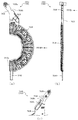
次いで、図21及び図22を参照して、第3ユニット600について説明する。図21は、第3ユニット600の正面分解斜視図であり、図22は、第3ユニット600の背面分解斜視図である。   Next, the third unit 600 will be described with reference to FIGS. 21 and 22. FIG. 21 is a front exploded perspective view of the third unit 600, and FIG. 22 is a rear exploded perspective view of the third unit 600.

図21及び図22に示すように、第3ユニット600は、第3ケース610と、その第3ケース610に配設されるスライド軸640と、そのスライド軸640に沿って案内されるラック部650と、そのラック部650のラックギヤ651に歯合されるピニオンギヤ680と、そのピニオンギヤ680を回転駆動する第3駆動モータ670と、ラック部650に連結される第3演出部材660と、を主に備える。   As shown in FIGS. 21 and 22, the third unit 600 includes a third case 610, a slide shaft 640 disposed in the third case 610, and a rack portion 650 guided along the slide shaft 640. And a pinion gear 680 that meshes with the rack gear 651 of the rack portion 650, a third drive motor 670 that rotationally drives the pinion gear 680, and a third effect member 660 connected to the rack portion 650. .

第3ケース610は、一面側(図21紙面手前側)が開放された箱状の第3ベース体620と、その第3ベース体620の一面側に締結固定され第3ベース体620の開放部分のうちの上方部分(図21上側)を閉封する第3カバー体630と、第3ベース体620の一面側に締結固定され第3ベース体620の開放部分のうちの第3カバー体630の下端よりも下方部分(図21下側)を閉封する平板状の平板カバー(図示せず)と、を備える。なお、これら第3ベース体620及び第3カバー体630と平板カバーとは無色の光透過性の樹脂材料から形成される。   The third case 610 includes a box-shaped third base body 620 that is open on one side (the front side in FIG. 21), and an open portion of the third base body 620 that is fastened and fixed to one surface of the third base body 620. A third cover body 630 that seals an upper portion (upper side in FIG. 21) of the first base body 620 and a third cover body 630 that is fastened and fixed to one surface side of the third base body 620. A flat plate cover (not shown) that seals the lower part (lower side in FIG. 21) from the lower end. The third base body 620, the third cover body 630, and the flat cover are formed from a colorless light-transmitting resin material.

第3ベース体620は、正面視において、中央に矩形状の開口621が開口形成されることで矩形枠状に形成されると共に、その矩形枠状の上辺中央から上方(図21上側)へ矩形状の部分が突出される形状に形成される。開口621は、第3ユニット600が第4ユニット700に積み重ねられた状態において(図5及び図6参照)、第4ユニット700(第4ベース体710)の開口711aに対応する位置および大きさに形成され、これら両開口621,711aを介して、第3図柄表示装置81(図2参照)の表示内容が視認可能とされる。   The third base body 620 is formed in a rectangular frame shape by forming a rectangular opening 621 in the center in a front view, and is rectangular upward from the center of the upper side of the rectangular frame shape (upper side in FIG. 21). The shape part is formed in a protruding shape. The opening 621 has a position and size corresponding to the opening 711a of the fourth unit 700 (fourth base body 710) when the third unit 600 is stacked on the fourth unit 700 (see FIGS. 5 and 6). The display content of the third symbol display device 81 (see FIG. 2) is visible through both the openings 621 and 711a.

第3ベース体620には、第4ケース710の台座部711e(図23参照)に締結固定される被締結部624が複数形成される。各被締結部624には、締結ねじが挿通される挿通孔が穿設されると共に、各被締結部624の座面(図22紙面手前側面)は、第3ベース体620の背面(図22紙面手前側面)と面一とされる。なお、本実施形態では、第3ベース体620には、正面視における上辺の2ヶ所および下辺の2ヶ所の合計4ヶ所に被締結部624が形成される。   In the third base body 620, a plurality of fastened portions 624 that are fastened and fixed to the pedestal portion 711e (see FIG. 23) of the fourth case 710 are formed. Each fastening portion 624 is provided with an insertion hole through which a fastening screw is inserted, and the seating surface (the front side surface in FIG. 22) of each fastening portion 624 is the back surface of the third base body 620 (FIG. 22). This is the same as the front side of the paper). In the present embodiment, the third base body 620 is formed with fastened portions 624 at a total of four locations, two locations on the upper side and two locations on the lower side in front view.

また、第3ベース体620及び第3カバー体630には、複数の台座部625,635が形成される。台座部625,635は、第1ユニット400及び第2ユニット500における被締結部425,525が締結固定される部位であり(図36及び図37参照)、これら各被締結部425,525に対応する位置に配置される。   The third base body 620 and the third cover body 630 are formed with a plurality of pedestal portions 625 and 635. The pedestal portions 625 and 635 are portions to which the fastened portions 425 and 525 in the first unit 400 and the second unit 500 are fastened and fixed (see FIGS. 36 and 37), and correspond to the fastened portions 425 and 525. It is arranged at the position to do.

第3カバー体630は、平板状に形成され、第3ベース体620の開放部分のうちの開口621の上辺よりも上方(図21上側)となる領域を閉封する。この第3カバー体630により閉封される領域において、スライド軸640、ラック部650、第3駆動モータ670及びピニオンギヤ680が第3ベース体620にそれぞれ配設される。   The third cover body 630 is formed in a flat plate shape, and closes a region above the upper side of the opening 621 (upper side in FIG. 21) in the open portion of the third base body 620. In the region sealed by the third cover body 630, the slide shaft 640, the rack portion 650, the third drive motor 670, and the pinion gear 680 are disposed on the third base body 620, respectively.

スライド軸640は、ラック部650のスライド移動方向を案内するための部材であり、第3ベース体620の幅寸法(図21左右方向寸法)と同等の長さを有する断面円形の棒状体として形成され、その長手方向を第3ベース体520の幅方向に向けた水平姿勢(即ち、開口621の上辺に平行な姿勢)で開口621の上方に配設される。   The slide shaft 640 is a member for guiding the slide movement direction of the rack portion 650, and is formed as a rod-shaped body having a circular cross section having a length equivalent to the width dimension of the third base body 620 (dimension in the left-right direction in FIG. 21). Then, it is disposed above the opening 621 in a horizontal posture (that is, a posture parallel to the upper side of the opening 621) with its longitudinal direction directed in the width direction of the third base body 520.

ラック部650は、スライド軸640の長手方向に沿ってスライド移動される断面矩形の箱状体であり、その箱状体の下面(図21下側面)には、第3演出部材660が配設されると共に、箱状体の正面側には、ラックギヤ651がスライド軸640の長手方向に沿って形成(刻設)される。ラックギヤ651には、ピニオンギヤ680が歯合され、ピニオンギヤ680には、第3駆動モータ670の駆動軸671に固着される駆動ギヤ672が歯合される。   The rack portion 650 is a box-shaped body having a rectangular cross section that is slid along the longitudinal direction of the slide shaft 640, and a third effect member 660 is disposed on the lower surface of the box-shaped body (the lower side surface in FIG. 21). At the same time, a rack gear 651 is formed (engraved) along the longitudinal direction of the slide shaft 640 on the front side of the box-shaped body. The rack gear 651 meshes with the pinion gear 680, and the pinion gear 680 meshes with the drive gear 672 fixed to the drive shaft 671 of the third drive motor 670.

第3ユニット600は、これら第3駆動モータ670、ピニオンギヤ680、ラック部650及び第3演出部材660からなる駆動機構を一対備え、それら一対の駆動機構が第3ベース体620の幅方向両側に対向して配設される。   The third unit 600 includes a pair of drive mechanisms including the third drive motor 670, the pinion gear 680, the rack portion 650, and the third effect member 660, and the pair of drive mechanisms are opposed to both sides in the width direction of the third base body 620. Arranged.

この駆動機構によれば、図21及び図22に示す退避位置から、一対の第3駆動モータ670が互いに逆方向に回転駆動されることにより、各ピニオンギヤ680が回転され、それらピニオンギヤ680の回転が各ラックギヤ651に伝達されることで、各ラック部650(第3演出部材660)がスライド軸640の長手方向に沿って開口621の中央へ向けてそれぞれスライド移動され、各第3演出部材660が開口621の形成領域内にそれぞれ張り出す張出位置(図示せず)に配置される。   According to this drive mechanism, the pair of third drive motors 670 are driven to rotate in opposite directions from the retracted positions shown in FIGS. 21 and 22, whereby each pinion gear 680 is rotated, and the rotation of these pinion gears 680 is caused. By being transmitted to each rack gear 651, each rack portion 650 (third effect member 660) is slid along the longitudinal direction of the slide shaft 640 toward the center of the opening 621, and each third effect member 660 is moved. They are arranged at overhanging positions (not shown) that protrude into the region where the opening 621 is formed.

一方、その張出位置から一対の第3駆動モータ670がそれぞれ上述の場合とは逆方向へ回転駆動されることで、各ラック部650(第3演出部材660)がスライド軸640の長手方向に沿って開口621の中央側から両脇(第3ベース体620の外縁)へ向けてそれぞれスライド移動され、各第3演出部材660が開口621の形成領域外にそれぞれ退避される退避位置(図21及び図22)に配置される。   On the other hand, the pair of third drive motors 670 are each driven to rotate in the opposite direction from the above-described case, so that each rack portion 650 (third effect member 660) extends in the longitudinal direction of the slide shaft 640. Along the opening 621 from the center side toward both sides (outer edges of the third base body 620), and the third rendering members 660 are respectively retracted outside the area where the opening 621 is formed (FIG. 21). And FIG. 22).

なお、本実施形態では、上記駆動機構が一対設けられるので、一対の第3演出部材660をそれぞれ独立にスライド移動させることができる。例えば、一対の第3駆動モータ670のうちの一方の第3駆動モータ670のみを回転駆動させることで、一対の第3演出部材660のうちの一方の第3演出部材660のみをスライド移動させることができる。或いは、一対の第3駆動モータ670を互いに同方向に回転駆動させることで、一対の第3演出部材660を同方向へスライド移動させることができる。   In the present embodiment, since a pair of the drive mechanisms is provided, the pair of third effect members 660 can be independently slid. For example, by rotating only one third drive motor 670 of the pair of third drive motors 670, only one third effect member 660 of the pair of third effect members 660 is slid. Can do. Alternatively, the pair of third drive members 660 can be slid in the same direction by rotating the pair of third drive motors 670 in the same direction.

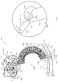
第3ベース体620には、図22に示すように、第3内側リブ622及び第3外側リブ623がその背面に形成される。第3内側リブ622及び第3外側リブ623は、第4ユニット700の第4演出部材760の先端側(先端部764L,764R)を案内するためのリブであり(図23参照)、断面半円状の突起として第3ベース体620の背面から突設されると共に、第3ベース体620の背面視において円弧状に湾曲して延設される。なお、第3ベース体620の背面視において、第3内側リブ622及び第3外側リブ623の右半分と左半分とは異なる位置を曲率中心として円弧状に湾曲される。   As shown in FIG. 22, the third base body 620 has a third inner rib 622 and a third outer rib 623 formed on the back surface thereof. The third inner rib 622 and the third outer rib 623 are ribs for guiding the tip side (tip portions 764L, 764R) of the fourth effect member 760 of the fourth unit 700 (see FIG. 23), and have a semicircular cross section. The protrusion is projected from the back surface of the third base body 620 as a protrusion, and is curved and extended in an arc shape in the rear view of the third base body 620. In addition, in the back view of the third base body 620, the third inner rib 622 and the third outer rib 623 are curved in an arc shape with different positions on the right half and the left half as the center of curvature.

第3内側リブ622は、その延設方向における2ヶ所が開口621により分断され、3分割される。3分割された第3内側リブ622は、開口621を挟んで位置する端部近傍において、第3ベース体620の背面からの立設高さが端部へ向かうに従って漸次低くされる(即ち、立設先端(図22紙面手前側)が端部へ向けて下降傾斜される)。この下降傾斜される領域を以下「傾斜部分622a」と称す。   The third inner rib 622 is divided into three parts by being divided by two openings 621 in the extending direction. The third inner rib 622 divided into three is gradually lowered from the back surface of the third base body 620 toward the end in the vicinity of the end located across the opening 621 (that is, upright The tip (the front side in FIG. 22) is inclined downward toward the end). This downwardly inclined region is hereinafter referred to as “inclined portion 622a”.

第3外側リブ623は、途中で分断されることなく、一端(図22右端)から他端(図22左端)までの全域にわたって連続して延設される。よって、左演出部材760L及び右演出部材760Rの先端部764L,764Rを、第3外側リブ623の突設高さの分だけ、第3ベース体620の背面から常に持ち上げておく(嵩上げしておく)ことができる。   The third outer rib 623 is continuously extended over the entire region from one end (the right end in FIG. 22) to the other end (the left end in FIG. 22) without being divided in the middle. Therefore, the front end portions 764L and 764R of the left effect member 760L and the right effect member 760R are always lifted from the back surface of the third base body 620 by the protruding height of the third outer rib 623. )be able to.

これにより、第3内側リブ622が途中で分断されている場合であっても(即ち、分断された箇所では先端部764L,764Rを第3ベース体620の背面から持ち上げられないので、左演出部材760L及び右演出部材760R(湾曲部761L,761R)が開口621の内周縁部に衝突する恐れがある)、左演出部材760L及び右演出部材760Rが右支持軸717R及び左支持軸717Lを回転中心として上昇位置および下降位置の間で回転する際に(図33から図35参照)、かかる左演出部材760L及び右演出部材760Rが開口621の内周縁部に衝突することを抑制することができる。   Thereby, even if the third inner rib 622 is divided in the middle (that is, the tip portions 764L and 764R cannot be lifted from the back surface of the third base body 620 at the divided portions, the left effect member) 760L and the right effect member 760R (the curved portions 761L and 761R may collide with the inner peripheral edge of the opening 621), the left effect member 760L and the right effect member 760R rotate about the right support shaft 717R and the left support shaft 717L. As shown in FIG. 33 to FIG. 35, the left effect member 760L and the right effect member 760R can be prevented from colliding with the inner peripheral edge of the opening 621 when rotating between the raised position and the lowered position.

なお、第3内側リブ622及び第3外側リブ623は、第3ユニット600が第4ユニット700に積み重ねられると(図5及び図6参照)、第4ユニット700の第4内側リブ714及び第4外側リブ715にそれぞれ対応する位置(正面視において重なる位置)に形成される。   The third inner rib 622 and the third outer rib 623 are arranged such that when the third unit 600 is stacked on the fourth unit 700 (see FIGS. 5 and 6), the fourth inner rib 714 and the fourth outer rib 714 of the fourth unit 700 are stacked. It is formed at a position corresponding to each of the outer ribs 715 (a position overlapping in front view).

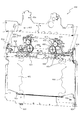
次いで、図23から図35を参照して、第4ユニット700について説明する。図23は、第4ユニット700の正面斜視図である。   Next, the fourth unit 700 will be described with reference to FIGS. FIG. 23 is a front perspective view of the fourth unit 700.

図23に示すように、第4ユニット700は、第4ケース710と、その第4ケース710に基端側が回転可能に軸支される第4演出部材760と、その第4演出部材760を回転させるための駆動力を発生する第4駆動モータ(図示せず)とを主に備える。ここで、図24から図29を参照して、第4ケースの詳細構成について説明する。   As shown in FIG. 23, the fourth unit 700 rotates a fourth case 710, a fourth effect member 760 that is pivotally supported by the fourth case 710 so that the base end side is rotatable, and the fourth effect member 760. And a fourth drive motor (not shown) that generates a driving force for the purpose. Here, a detailed configuration of the fourth case will be described with reference to FIGS. 24 to 29.

図24は、第4ケース710の正面斜視図であり、正面カバー716が取り外された状態が図示される。   FIG. 24 is a front perspective view of the fourth case 710, illustrating a state where the front cover 716 is removed.

図24に示すように、第4ケース710は、底面板711と、その底面板711の外縁から立設される壁部712とを備える。底面板711は、正面視において、中央に矩形状の開口711aが開口形成されることで矩形枠状に形成されると共に、その矩形枠状の上辺中央から上方(図23上側)へ矩形状の部分が突出される形状に形成される。即ち、第4ケース710の底面板711は、その正面視形状が、第3ユニット600の第3ベース体620(図21及び図22参照)の正面視形状と略同一に形成される。   As shown in FIG. 24, the fourth case 710 includes a bottom plate 711 and a wall portion 712 standing from the outer edge of the bottom plate 711. The bottom plate 711 is formed in a rectangular frame shape by opening a rectangular opening 711a in the center in a front view, and has a rectangular shape upward from the center of the upper side of the rectangular frame shape (upper side in FIG. 23). The part is formed in a protruding shape. That is, the bottom plate 711 of the fourth case 710 has a front view shape substantially the same as the front view shape of the third base body 620 (see FIGS. 21 and 22) of the third unit 600.

なお、底面板711には、複数の台座部711eが形成される。台座部711eは、第3ユニット600における第3ケース610の被締結部624が締結固定される部位であり(図36及び図37参照)、第3ケース610の被締結部624に対応する位置に配置される。   A plurality of pedestal portions 711 e are formed on the bottom plate 711. The pedestal portion 711e is a portion to which the fastened portion 624 of the third case 610 in the third unit 600 is fastened and fixed (see FIGS. 36 and 37), and is in a position corresponding to the fastened portion 624 of the third case 610. Be placed.

また、壁部712には、台座部711fと複数の被締結孔712aとが形成される。台座部711fは、第2ユニット500における第2ベース体520(被締結部526)が締結固定される部位であり(図36及び図37参照)、第2ベース体520の被締結部526に対応する位置に配置される。被締結孔712aは、第1ユニット400における装飾連結板450が締結固定される部位であり(図36及び図37参照)、装飾連結板450の挿通孔451に対応する位置に配置される。   In addition, a pedestal portion 711f and a plurality of fastening holes 712a are formed in the wall portion 712. The pedestal portion 711f is a portion to which the second base body 520 (fastened portion 526) in the second unit 500 is fastened and fixed (see FIGS. 36 and 37), and corresponds to the fastened portion 526 of the second base body 520. It is arranged at the position to do. The to-be-fastened hole 712a is a part to which the decorative connecting plate 450 in the first unit 400 is fastened and fixed (see FIGS. 36 and 37), and is disposed at a position corresponding to the insertion hole 451 of the decorative connecting plate 450.

ここで、台座部711fの周囲には、正面視L字状に延設される規制壁711faが立設される。規制壁711Faは、第2ベース体520の被締結部526(図15参照)の外形に対応して形成され、台座部711fに被締結部526が締結固定される際には、その被締結部526の外縁(外側面)に規制壁711faの内壁面が対面(又は、当接)される。これにより、台座部711fに被締結部526を載置する(即ち、第2ユニット500を第4ユニット700に連結するために、第3ユニット600の正面に第2ユニット500を積み重ねる、図37参照)際には、台座部711fに対する被締結部526の位置決めを、規制壁711faを利用して行うことができる。よって、その組み付け性の向上を図ることができる。   Here, around the base portion 711f, a restriction wall 711fa extending in an L shape in front view is erected. The restriction wall 711Fa is formed corresponding to the outer shape of the fastened portion 526 (see FIG. 15) of the second base body 520, and when the fastened portion 526 is fastened and fixed to the pedestal portion 711f, the fastened portion The inner wall surface of the regulating wall 711fa faces (or abuts) the outer edge (outer surface) of 526. Accordingly, the fastened portion 526 is placed on the pedestal portion 711f (that is, the second unit 500 is stacked on the front surface of the third unit 600 in order to connect the second unit 500 to the fourth unit 700, see FIG. 37). ), Positioning of the fastened portion 526 with respect to the pedestal portion 711f can be performed using the restriction wall 711fa. Therefore, the assembling property can be improved.

また、規制部711faが被締結部526の外縁の2辺を取り囲むので、被締結部526が台座部711f上で移動する(位置ずれする)ことを規制部711faにより規制できる。よって、第4ユニット700に対する第2ユニット500の連結強度を高めることができ、動作ユニット300のぐらつき(第4ユニット700に対する第3ユニット600及び第2ユニット500の変位)を抑制できる。   Further, since the restricting portion 711fa surrounds two sides of the outer edge of the fastened portion 526, the restricting portion 711fa can restrict the fastened portion 526 from moving (displacement) on the pedestal portion 711f. Therefore, the connection strength of the second unit 500 with respect to the fourth unit 700 can be increased, and wobbling of the operation unit 300 (displacement of the third unit 600 and the second unit 500 with respect to the fourth unit 700) can be suppressed.

更に、台座部711fは、第4ケース710の壁部712の立設先端から外方(図24右側)へ張り出して形成されるので、壁部712の内壁面側に設ける場合と比較して、第4ケース710への各ユニット400〜600の収容可能量を確保できるだけでなく、かかる台座部711fが補強リブとして機能することで、第4ケース体710自体の剛性を高めることができる。その結果、動作ユニット300全体としての剛性を高め、各演出部材460〜760の動作時におけるぐらつきを抑制することができる。   Furthermore, since the pedestal portion 711f is formed to project outward (right side in FIG. 24) from the standing tip of the wall portion 712 of the fourth case 710, compared to the case where it is provided on the inner wall surface side of the wall portion 712, Not only can the amount of each unit 400-600 accommodated in the fourth case 710 be ensured, but the rigidity of the fourth case body 710 itself can be increased by the pedestal portion 711f functioning as a reinforcing rib. As a result, the rigidity of the entire operation unit 300 can be increased, and wobbling during the operation of each effect member 460 to 760 can be suppressed.

同様に、被締結孔712aは、第4ケース710の壁部712の立設先端から外方(図24上側)へフランジ状に張り出して形成される部位に形成されるので、壁部712の内壁面側に設ける場合と比較して、第4ケース710への各ユニット400〜600の収容可能量を確保できるだけでなく、かかるフランジ状に形成される部位(被締結孔712aが形成さえる部位)が補強リブとして機能することで、第4ケース体710自体の剛性を高めることができる。その結果、動作ユニット300全体としての剛性を高め、各演出部材460〜760の動作時におけるぐらつきを抑制することができる。   Similarly, the fastened hole 712a is formed in a portion that is formed in a flange-like shape so as to protrude outward (upper side in FIG. 24) from the standing tip of the wall portion 712 of the fourth case 710. Compared with the case where it is provided on the wall surface side, not only can the amount of each unit 400-600 accommodated in the fourth case 710 be ensured, but also the portion formed in the flange shape (the portion where the tightened hole 712a can be formed). By functioning as a reinforcing rib, the rigidity of the fourth case body 710 itself can be increased. As a result, the rigidity of the entire operation unit 300 can be increased, and wobbling during the operation of each effect member 460 to 760 can be suppressed.

底面板711は、駆動部配設凹部711bと、第4基側リブ713と、第4内側リブ714及び第4外側リブ715とを備える。駆動部配設凹部711bは、第4演出部材760を回転駆動するための駆動手段が配設される部位であり、底面板711の幅方向(図24左右方向)中央であって開口711aの上方に位置し、正面視矩形の凹部として底面板711に凹設される。   The bottom plate 711 includes a drive unit disposition recess 711 b, a fourth base rib 713, a fourth inner rib 714, and a fourth outer rib 715. The driving portion disposing recess 711b is a portion where driving means for rotationally driving the fourth effect member 760 is disposed, and is the center in the width direction (left and right direction in FIG. 24) of the bottom plate 711 and above the opening 711a. Is located in the bottom plate 711 as a rectangular recess in front view.

駆動部配設凹部711bには、その外縁に沿って支持壁711cが立設され、その支持壁711cの立設先端には、正面カバー716が締結固定される。正面カバー716は、正面視横長の矩形状に形成され、駆動部配設凹部711bの上側部分(図24上側)のみに覆設される。   A support wall 711c is erected along the outer edge of the driving portion disposing recess 711b, and a front cover 716 is fastened and fixed to the erected tip of the support wall 711c. The front cover 716 is formed in a rectangular shape that is horizontally long when viewed from the front, and is covered only on the upper portion (upper side in FIG. 24) of the driving portion disposing recess 711b.

よって、正面カバー716の下端側(開口711a側、図24下側)が開放された状態とされるので(図23参照)、この開放部分を利用して第4演出部材760の基部側を後述する右支持軸717R及び左支持軸717Lに軸支させると共に、その軸支部分を中心に第4演出部材760を回転させることができる。また、正面カバー716の背面(図24紙面奥側面)には、正面視円形の保持凹部(図示せず)が一対凹設され、これら一対の保持凹部に右支持軸717R及び左支持軸717Lの先端がそれぞれ内嵌され保持される。ここで、図25及び図26を参照して、駆動部配設凹部711bに配設される駆動手段について説明する。   Therefore, since the lower end side (opening 711a side, lower side in FIG. 24) of the front cover 716 is opened (see FIG. 23), the base side of the fourth effect member 760 will be described later using this opened portion. While being supported by the right support shaft 717R and the left support shaft 717L, the fourth effect member 760 can be rotated around the shaft support portion. In addition, a pair of holding recesses (not shown) that are circular in front view are provided on the back surface of the front cover 716 (the back side surface in FIG. 24), and the right support shaft 717R and the left support shaft 717L are provided in the pair of holding recesses. Each tip is fitted and held. Here, with reference to FIG. 25 and FIG. 26, the drive means arrange | positioned at the drive part arrangement | positioning recessed part 711b is demonstrated.

図25は、駆動部配設凹部711bを部分的に拡大した第4ケース710の部分拡大正面図であり、図26は、駆動部配設凹部711bを部分的に拡大した第4ケース710の部分拡大正面斜視図である。なお、図26では、右ギヤ部材790Rが取り外された状態が図示されると共に、左ギヤ部材790L及び右ギヤ部材790Rの回転方向の位置決めを行うための位置決め冶具JGが図示される。   FIG. 25 is a partially enlarged front view of the fourth case 710 in which the driving portion disposing recess 711b is partially enlarged. FIG. 26 is a portion of the fourth case 710 in which the driving portion disposing recess 711b is partially enlarged. It is an enlarged front perspective view. FIG. 26 illustrates a state in which the right gear member 790R is removed and a positioning jig JG for positioning the left gear member 790L and the right gear member 790R in the rotational direction.

図25及び図26に示すように、駆動部配設凹部711bには、右支持軸717R及び左支持軸717Lと、駆動ギヤ770と、方向変換ギヤ780と、右ギヤ部材790R及び左ギヤ部材790Lとが配設される。方向変換ギヤ780は図示しない支持軸により、右ギヤ部材790R及び左ギヤ部材790Lはギヤ軸718により、それぞれ駆動部配設凹部711bの底面に回転可能に軸支される。なお、ギヤ軸718の先端には、円周溝が凹設され、その円周溝に嵌め込まれる止め輪Mが、右ギヤ部材790R及び左ギヤ部材790Lの抜け止めとされる。   As shown in FIGS. 25 and 26, the drive portion disposing recess 711b includes a right support shaft 717R and a left support shaft 717L, a drive gear 770, a direction changing gear 780, a right gear member 790R and a left gear member 790L. Are arranged. The direction change gear 780 is rotatably supported on the bottom surface of the driving portion disposing recess 711b by the support shaft (not shown) and the right gear member 790R and the left gear member 790L by the gear shaft 718, respectively. A circumferential groove is recessed at the tip of the gear shaft 718, and a retaining ring M fitted into the circumferential groove is used to prevent the right gear member 790R and the left gear member 790L from coming off.

右支持軸717R及び左支持軸717Lは、第4演出部材760の基端側を回転可能に軸支するための部材であり(図33から図35参照)、真鋳材料から円柱状に形成される。これら右支持軸717R及び左支持軸717Lは、第4ケース710の幅方向(図25左右方向)に所定間隔を隔てて配設され、かつ、駆動部配設凹部711bの底面から前方(図25紙面手前側)へ向けて共に垂直に立設される。   The right support shaft 717R and the left support shaft 717L are members for rotatably supporting the base end side of the fourth effect member 760 (see FIGS. 33 to 35), and are formed in a column shape from a true cast material. The The right support shaft 717R and the left support shaft 717L are disposed at a predetermined interval in the width direction of the fourth case 710 (left and right direction in FIG. 25), and forward from the bottom surface of the drive unit disposition recess 711b (FIG. 25). Both are set up vertically toward the front side of the page).

駆動部配設凹部711bの背面側(図25紙面奥側)には、第4駆動モータ(図示せず)が配設される。第4駆動モータの駆動軸に固着される駆動ギヤ770には、方向変換ギヤ780と右ギヤ部材790Rとがそれぞれ歯合され、方向変換ギヤ780には、左ギヤ部材790Lが歯合される。よって、第4駆動モータの駆動軸が回転駆動されると、その駆動軸の回転駆動力が、右ギヤ部材790Rに直接伝達されると共に、左ギヤ部材790Lに方向変換ギヤ780を介して伝達され、これにより、右ギヤ部材790R及び左ギヤ部材790Lがそれぞれ逆方向に回転される。   A fourth drive motor (not shown) is provided on the back side (the back side in FIG. 25) of the drive unit disposition recess 711b. The direction change gear 780 and the right gear member 790R are meshed with the drive gear 770 fixed to the drive shaft of the fourth drive motor, and the left gear member 790L is meshed with the direction change gear 780. Therefore, when the drive shaft of the fourth drive motor is rotationally driven, the rotational driving force of the drive shaft is directly transmitted to the right gear member 790R and also transmitted to the left gear member 790L via the direction change gear 780. As a result, the right gear member 790R and the left gear member 790L are rotated in opposite directions.

なお、駆動ギヤ770と方向変換ギヤ780とは、同じ歯数のギヤとして形成される。即ち、方向変換ギヤ780は、駆動ギヤ770の回転を、減速せずに、方向のみを変換して左ギヤ部材790Lに伝達するので、右ギヤ部材790Rと左ギヤ部材790Lとは、同じ回転速度で逆方向に回転される。   Drive gear 770 and direction changing gear 780 are formed as gears having the same number of teeth. That is, the direction changing gear 780 converts only the direction without transmitting the rotation of the driving gear 770 and transmits it to the left gear member 790L, so that the right gear member 790R and the left gear member 790L have the same rotational speed. Is rotated in the opposite direction.

駆動部配設凹部711bには、図26に示すように、ギヤ軸718の径方向外方に位置決め孔711hが貫通形成されると共に、ギヤ軸718の径方向外方に回転位置検出センサSが配設される。位置決め孔711hは、後述するように、位置決め冶具JGの挿入部JGbが挿入される断面円形の孔である。   As shown in FIG. 26, a positioning hole 711h is formed through the drive unit disposing recess 711b radially outward of the gear shaft 718, and a rotational position detection sensor S is provided radially outward of the gear shaft 718. Arranged. As will be described later, the positioning hole 711h is a hole having a circular cross section into which the insertion portion JGb of the positioning jig JG is inserted.

回転位置検出センサRは、発光部Ra及び受光部Rbを備えた光センサであり、それら発光部Ra及び受光部Rbの対向空間を、右ギヤ部材790Rの環状リブ793(図27及び図28参照)の移動軌跡上に配置する(即ち、発光部Ra及び受光部Rbが環状リブ793(図27参照)を内周側および外周側から挟み込む位置に配置される)。これにより、間欠部793aの有無に基づいて、右ギヤ部材790の回転位置を検出する。ここで、図27及び図28を参照して、右ギヤ部材790について説明する。   The rotational position detection sensor R is an optical sensor including a light emitting portion Ra and a light receiving portion Rb, and an annular rib 793 (see FIGS. 27 and 28) of the right gear member 790R is formed in an opposing space between the light emitting portion Ra and the light receiving portion Rb. (That is, the light emitting portion Ra and the light receiving portion Rb are disposed at positions where the annular rib 793 (see FIG. 27) is sandwiched from the inner peripheral side and the outer peripheral side). Thus, the rotational position of the right gear member 790 is detected based on the presence or absence of the intermittent portion 793a. Here, the right gear member 790 will be described with reference to FIGS. 27 and 28.

図27は、右ギヤ部材790Rの背面斜視図である。また、図28(a)は、右ギヤ部材790Rの背面図であり、図28(b)は、図28(a)のXXVIIIb−XXVIIIb線における右ギヤ部材790Rの断面図である。   FIG. 27 is a rear perspective view of the right gear member 790R. FIG. 28A is a rear view of the right gear member 790R, and FIG. 28B is a cross-sectional view of the right gear member 790R taken along line XXVIIIb-XXVIIIb in FIG.

図27及び図28に示すように、右ギヤ部材790Rは、ギヤ本体791と、そのギヤ本体791の正面側(図28(b)下側の面)から突設される突設ピン792と、その突設ピン792とは反対側となるギヤ本体の背面側から突設される環状リブ793とを備え、これらギヤ本体791、突設ピン792及び環状リブ793が樹脂材料から一体に形成される。   As shown in FIGS. 27 and 28, the right gear member 790R includes a gear main body 791, a protruding pin 792 protruding from the front side of the gear main body 791 (the lower surface in FIG. 28 (b)), An annular rib 793 projecting from the back side of the gear body opposite to the projecting pin 792 is provided, and the gear body 791, the projecting pin 792 and the annular rib 793 are integrally formed from a resin material. .

ギヤ本体791は、円板状に形成され、その中心には、ギヤ軸718(図26参照)が挿通される軸支孔791aが軸方向(図28(b)上下方向)に沿って貫通形成されると共に、その軸支孔791aから偏心した位置に位置決め冶具JG(図26参照)が挿通される位置決め孔791bが軸方向に沿って貫通形成される。軸支孔791a及び位置決め孔791bは共に断面円形の孔として形成される。またギヤ本体791の外周面には、略半周にわたって歯が刻設される。突設ピン792は、円柱状に形成され、ギヤ本体791の軸心(軸支孔791a)に平行に突設されると共に、ギヤ本体791の軸心から偏心して位置する。   The gear body 791 is formed in a disc shape, and a shaft support hole 791a through which the gear shaft 718 (see FIG. 26) is inserted penetrates the center of the gear body 791 in the axial direction (FIG. 28 (b) vertical direction). In addition, a positioning hole 791b through which the positioning jig JG (see FIG. 26) is inserted at a position eccentric from the shaft support hole 791a is formed penetrating along the axial direction. Both the shaft support hole 791a and the positioning hole 791b are formed as holes having a circular cross section. Further, teeth are engraved on the outer peripheral surface of the gear body 791 over a substantially half circumference. The projecting pin 792 is formed in a columnar shape, projects in parallel with the shaft center (shaft support hole 791a) of the gear main body 791, and is offset from the shaft center of the gear main body 791.

突設ピン792には、摺動筒L(図26参照)が回転可能に取着される。摺動筒Lは、軸支孔を有する円筒状の本体部と、その本体部の軸方向端部から径方向外方へ向けて張り出すフランジ状のフランジ部とからなり、フランジ部をギヤ本体791の正面へ向けた姿勢で突設ピン792に取着される。即ち、摺動筒Lは、フランジ部の直径が後述する左演出部材760L及び右演出部材760Rの案内溝762La,762Ra(図31及び図32参照)の溝幅よりも大きくされると共に、本体部の直径が左演出部材760L及び右演出部材760Rの案内溝762La,762Raの溝幅よりも若干小さくされ、本体部が案内溝762La,762Ra内に摺動可能に挿通される。   A sliding cylinder L (see FIG. 26) is rotatably attached to the projecting pin 792. The sliding cylinder L includes a cylindrical main body portion having a shaft support hole and a flange-like flange portion projecting radially outward from the axial end portion of the main body portion. 791 is attached to the projecting pin 792 in a posture toward the front. That is, the sliding cylinder L has a diameter of the flange portion larger than the groove widths of guide grooves 762La and 762Ra (see FIGS. 31 and 32) of the left effect member 760L and the right effect member 760R, which will be described later, and the main body portion. Are slightly smaller than the groove widths of the guide grooves 762La and 762Ra of the left effect member 760L and the right effect member 760R, and the main body is slidably inserted into the guide grooves 762La and 762Ra.

環状リブ793は、回転位置検出センサRによって検出される部位であり、円筒状(即ち、図28(a)に示す背面視において円環状)に形成される。環状リブ793には、その周方向の一部(本実施形態では中心角15度)を切り欠く(分断する)ことで、間欠部793aが形成される。   The annular rib 793 is a portion detected by the rotational position detection sensor R, and is formed in a cylindrical shape (that is, an annular shape in the rear view shown in FIG. 28A). An intermittent portion 793a is formed in the annular rib 793 by notching (dividing) a portion in the circumferential direction (a central angle of 15 degrees in the present embodiment).

ここで、ギヤ軸718に右ギヤ部材790Rが軸支されると(図25及び図26参照)、回転位置検出センサRの発光部Ra及び受光部Rbの対向面間に環状リブ793が配設される。よって、回転位置検出センサRは、発光部Raから照射した光が、環状リブ793により遮られて受光部Rbで受光不能であるか、或いは、間欠部793aを通過して受光部Rbで受光可能であるかに応じて、右ギヤ部材790Rの回転位置を検出することができる。   Here, when the right gear member 790R is pivotally supported by the gear shaft 718 (see FIGS. 25 and 26), an annular rib 793 is disposed between the opposed surfaces of the light emitting portion Ra and the light receiving portion Rb of the rotational position detection sensor R. Is done. Therefore, the rotation position detection sensor R can receive the light emitted from the light emitting portion Ra by the light receiving portion Rb because it is blocked by the annular rib 793 or passes through the intermittent portion 793a. Depending on whether or not, the rotational position of the right gear member 790R can be detected.

このように、ギヤ部材790Rは、ギヤ本体791の背面に円筒状の環状リブ793を立設すると共に、その環状リブ793の一部を切り欠いて間欠部793aを形成することで、回転位置検出センサRによる回転位置の検出を可能としつつ、同時にギヤ部材790Rの剛性の向上を図ることができる。例えば、ギヤ本体791の外周面であって、歯が刻設されていない部分から径方向外方へ板状の被検出板を張り出させて、その被検出板を、ギヤ本体791の外周側に配置した回転位置検出センサRにより検出する構成も考えられる。   As described above, the gear member 790R has a cylindrical annular rib 793 standing on the back surface of the gear body 791, and a part of the annular rib 793 is cut away to form an intermittent portion 793a, thereby detecting the rotational position. While the rotation position can be detected by the sensor R, the rigidity of the gear member 790R can be improved at the same time. For example, a plate-shaped detection plate is projected outwardly from the outer peripheral surface of the gear main body 791 where no teeth are engraved, and the detection plate is connected to the outer peripheral side of the gear main body 791. A configuration is also conceivable in which detection is performed by a rotational position detection sensor R disposed in the position.

しかし、この構成では、径方向外方へ張り出させた被検出板の移動空間をギヤ部材790Rの周囲に確保する必要があるため、ギヤ部材790Rの配設に必要なスペースが嵩む。また、このような板状の被検出板を外周面から張り出させたとしても、ギヤ本体791の剛性の向上は見込めない。   However, in this configuration, since it is necessary to secure a space for moving the detection plate projecting outward in the radial direction around the gear member 790R, a space necessary for disposing the gear member 790R increases. Further, even if such a plate-like detection plate is projected from the outer peripheral surface, the improvement of the rigidity of the gear body 791 cannot be expected.

これに対し、本実施形態では、ギヤ本体791の背面に環状リブ793が立設される構成なので、ギヤ本体791の外周側に移動空間を確保することが不要となり、ギヤ部材790Rの配設に必要なスペースを抑制できる。また、円筒状の環状リブ793がギヤ本体791の背面に立設されることで、かかるギヤ本体791の剛性の向上を図ることができる。   On the other hand, in this embodiment, since the annular rib 793 is erected on the back surface of the gear main body 791, it is not necessary to secure a movement space on the outer peripheral side of the gear main body 791, and the gear member 790R is disposed. Necessary space can be reduced. Further, since the cylindrical annular rib 793 is erected on the back surface of the gear main body 791, the rigidity of the gear main body 791 can be improved.

なお、右ギヤ部材790R及び左ギヤ部材790Lは、対称形状に形成され、その要素は同一の構成である。よって、対応する構成には同一の符号を付して、その説明を省略する。   The right gear member 790R and the left gear member 790L are formed in a symmetrical shape, and the elements have the same configuration. Accordingly, corresponding components are denoted by the same reference numerals, and description thereof is omitted.

図25及び図26に戻って、以上のように形成される左ギヤ部材790L及び右ギヤ部材790Rの駆動部配設凹部711bへの組み付け方法について説明する。なお、位置決め冶具JGは、作業者が把持するための把持部JGaと、その把持部JGaと同軸状に形成される円柱状の挿入部JGbと、それら把持部JGa及び挿入部JGbの間に配設され径方向外方へ張り出すフランジ部JGcとを備えて形成される。   Returning to FIG. 25 and FIG. 26, a method of assembling the left gear member 790L and the right gear member 790R formed as described above into the driving portion disposing recess 711b will be described. The positioning jig JG is disposed between a gripping portion JGa for an operator to grip, a columnar insertion portion JGb formed coaxially with the gripping portion JGa, and the gripping portion JGa and the insertion portion JGb. And a flange portion JGc extending outward in the radial direction.

左ギヤ部材790L及び右ギヤ部材790Rを駆動部配設凹部711bへ組み付ける(ギヤ軸718に軸支させる)際には、左ギヤ部材790L及び右ギヤ部材790Rの回転方向の位置決め(位相合わせ)を行う必要がある。これら左ギヤ部材790L及び右ギヤ部材790Rの回転方向位置(位相)が適正な回転方向位置からずれていると、突設ピン792を介して連結される左演出部材760L及び右演出部材760R(図33から図35参照)の相対位置がずれ、例えば、下降位置において互いの合わせ面761La,761Raを適正に当接させることができなくなる(隙間が形成される、或いは、過大に密着して破損を招く)からである。   When the left gear member 790L and the right gear member 790R are assembled to the drive unit disposition recess 711b (supported by the gear shaft 718), the left gear member 790L and the right gear member 790R are positioned in the rotational direction (phase alignment). There is a need to do. When the rotation direction position (phase) of the left gear member 790L and the right gear member 790R deviates from the proper rotation direction position, the left effect member 760L and the right effect member 760R connected via the projecting pin 792 (see FIG. 33, see FIG. 35), for example, the mating surfaces 761La and 761Ra cannot be properly brought into contact with each other at the lowered position (a gap is formed, or excessive contact is caused and damage is caused). Because it invites).

本実施形態では、位置決め冶具JGを使用することで、左ギヤ部材790L及び右ギヤ部材790Rを適正な回転方向位置(位相)で駆動部配設凹部711bへ組み付けることができる。例えば、右ギヤ部材790Rを駆動部配設凹部711bに組み付ける際には、まず、位置決め冶具JGの挿入部JGbを右ギヤ部材790Rの位置決め孔791bに挿入し、その挿入部JGbの先端を右ギヤ部材790R(ギヤ本体791)の背面から突出させる。次いで、ギヤ軸718の先端を右ギヤ部材790R(ギヤ本体791)の挿通孔791aに挿通させつつ、右ギヤ部材790R(ギヤ本体791)の背面から突出される挿入部JGbの先端を駆動部配設凹部711bの位置決め孔711に挿入させる。   In the present embodiment, by using the positioning jig JG, the left gear member 790L and the right gear member 790R can be assembled to the drive unit disposition recess 711b at an appropriate rotational direction position (phase). For example, when assembling the right gear member 790R into the driving portion disposing recess 711b, first, the insertion portion JGb of the positioning jig JG is inserted into the positioning hole 791b of the right gear member 790R, and the tip of the insertion portion JGb is inserted into the right gear. The member 790R (gear body 791) is projected from the back surface. Next, while inserting the tip of the gear shaft 718 into the insertion hole 791a of the right gear member 790R (gear body 791), the tip of the insertion part JGb protruding from the back surface of the right gear member 790R (gear body 791) is arranged in the drive unit. It inserts in the positioning hole 711 of the installation recessed part 711b.

これにより、右ギヤ部材790Rのギヤ軸718を回転中心とする回転方向位置(位相)を位置決めすることができるので、この姿勢を維持した状態で、右ギヤ部材790Rを駆動ギヤ770に歯合させることで、右ギヤ部材790Rを適正な状態で組み付けることができる。なお、左ギヤ部材790Lの駆動部配設凹部711bへの組み付け方法も同様であるので、その説明は省略する。   As a result, the rotational direction position (phase) around the gear shaft 718 of the right gear member 790R can be positioned, so that the right gear member 790R meshes with the drive gear 770 while maintaining this posture. Thus, the right gear member 790R can be assembled in an appropriate state. Since the method for assembling the left gear member 790L to the driving portion disposing recess 711b is the same, the description thereof is omitted.

図24に戻って説明する。第4基部リブ713は、駆動部配設凹部711bと開口711aとの間において、第4ケース710の底面板711から立設される。第4基部リブ713は、第4ユニット700の第4演出部材760(図23参照)の基端側を案内するためのリブであり、断面半円状の突起として底面板711の正面から突設されると共に、右支持軸717R及び左支持軸717L側に中心を有する円弧状に湾曲して延設される。   Returning to FIG. The fourth base rib 713 is erected from the bottom plate 711 of the fourth case 710 between the drive unit disposition recess 711b and the opening 711a. The fourth base rib 713 is a rib for guiding the base end side of the fourth effect member 760 (see FIG. 23) of the fourth unit 700, and protrudes from the front surface of the bottom plate 711 as a semicircular cross section. At the same time, it is curved and extended in an arc shape having centers on the right support shaft 717R and the left support shaft 717L side.

第4内側リブ714及び第4外側リブ715は、開口711aの下方側(図24下側)において、第4ケース710の底面板711から立設される。ここで、図29を参照して、第4内側リブ714及び第4外側リブ715について説明する。   The fourth inner rib 714 and the fourth outer rib 715 are erected from the bottom plate 711 of the fourth case 710 on the lower side (lower side in FIG. 24) of the opening 711a. Here, the fourth inner rib 714 and the fourth outer rib 715 will be described with reference to FIG.

図29は、第4内側リブ714及び第4外側リブ715が形成される領域を部分的に拡大した第4ケース710の部分拡大正面図である。図29に示すように、第4内側リブ714及び第4外側リブ715は、第4ユニット700の第4演出部材760の先端側(先端部760L,760R)を案内するためのリブであり(図23参照)、断面半円状の突起として第4ケース710の底面板411の正面から突設される。   FIG. 29 is a partially enlarged front view of the fourth case 710 in which a region where the fourth inner rib 714 and the fourth outer rib 715 are formed is partially enlarged. As shown in FIG. 29, the fourth inner rib 714 and the fourth outer rib 715 are ribs for guiding the tip side (tip portions 760L, 760R) of the fourth effect member 760 of the fourth unit 700 (see FIG. 29). 23), and is projected from the front surface of the bottom plate 411 of the fourth case 710 as a semicircular cross section.

ここで、第4内側リブ714及び第4外側リブ715は、第4ケース710における底面板711の正面視において、右側部分(右支持軸717Rの下方に位置する部分、図29右側部分)が左支持軸717Lを中心とする円弧状に湾曲して延設される一方、左側部分(左支持軸717Lの下方に位置する部分、図24左側部分)が右支持軸717Rを中心とする円弧状に湾曲して延設される。なお、中央部分は、右側部分および左側部分を滑らかに接続した円弧状に湾曲して延設される。これにより、第4演出部材760の先端側(先端部760L,760R)をスムーズに案内することができる。   Here, in the fourth inner rib 714 and the fourth outer rib 715, the right side portion (the portion located below the right support shaft 717R, the right portion in FIG. 29) is the left in the front view of the bottom plate 711 in the fourth case 710. The left side portion (the portion located below the left support shaft 717L, the left side portion in FIG. 24) has an arc shape centered on the right support shaft 717R, while being curved and extended in an arc shape centering on the support shaft 717L. Curved and extended. The central portion is curved and extended in an arc shape in which the right side portion and the left side portion are smoothly connected. Thereby, the front end side (front-end | tip part 760L, 760R) of the 4th production member 760 can be guided smoothly.

第4内側リブ714は、第3ベース体620における第3内側リブ622と同様に(図22参照)、その延設方向における2ヶ所が開口711aにより分断される。また、第4ケース710では、第4外側リブ715も、その延設方向における2ヶ所が分断される。なお、この第4外側リブ715が分断される領域(第4外側リブ715が非形成の領域)を以下「分断領域711d」と称す。よって、分断領域711dは、第4ケース710の底面板711の正面と面一な平坦面として形成される。   As with the third inner rib 622 in the third base body 620 (see FIG. 22), the fourth inner rib 714 is divided by two openings 711a in the extending direction. In the fourth case 710, the fourth outer rib 715 is also divided at two points in the extending direction. The region where the fourth outer rib 715 is divided (the region where the fourth outer rib 715 is not formed) is hereinafter referred to as “divided region 711d”. Therefore, the dividing region 711 d is formed as a flat surface that is flush with the front surface of the bottom plate 711 of the fourth case 710.

このように、2ヶ所が分断されることで、3分割された第4内側リブ714は、開口711aを挟んで位置する端部近傍において、底面板711からの立設高さが端部へ向かうに従って漸次低くされる(即ち、立設先端(図29紙面手前側)が端部へ向けて下降傾斜される)。この下降傾斜される領域を以下「傾斜部分714a」と称す。   As described above, the four inner ribs 714 that are divided into three portions are separated from each other at two locations so that the standing height from the bottom plate 711 is directed toward the end portion in the vicinity of the end portion that is located across the opening 711a. (Ie, the standing tip (the front side in FIG. 29) is inclined downward toward the end). This downwardly inclined region is hereinafter referred to as “inclined portion 714a”.

同様に、2ヶ所が分断されることで、3分割された第4外側リブ715は、分断領域711dを挟んで位置する端部近傍において、底面板711からの立設高さが端部へ向かうに従って漸次低くされる(立設先端が端部へ向けて下降傾斜される)。この下降傾斜される領域を以下「傾斜部分715a」と称す。   Similarly, when the four outer ribs 715 divided into three parts are divided in two places, the standing height from the bottom plate 711 is directed toward the end part in the vicinity of the end part located across the dividing region 711d. (The standing tip is inclined downward toward the end). This downwardly inclined region is hereinafter referred to as “inclined portion 715a”.

なお、分断領域711dの形成領域の幅(第4外側リブ715が分断される延設方向の長さ)は、第4演出部材760の先端部760L,760Rの幅寸法(図31(a)及び図31(d)の左右方向寸法)よりも若干大きくされる。また、3分割された第4内側リブ714のうちの中央の第4内側リブ714の傾斜部分714aは、第4演出部材760の先端部760L,760Rが分断領域711dに位置する場合に、その先端部760L,760Rを支持可能な範囲(正面視において先端部760L,760Rに重なる範囲)に形成される(図34参照)。   The width of the formation region of the dividing region 711d (the length in the extending direction in which the fourth outer rib 715 is divided) is the width dimension of the tip portions 760L and 760R of the fourth effect member 760 (FIG. 31A and FIG. It is slightly larger than the dimension in the left-right direction in FIG. In addition, the inclined portion 714a of the fourth inner rib 714 at the center of the fourth inner ribs 714 divided into three is the tip when the tip portions 760L and 760R of the fourth effect member 760 are located in the dividing region 711d. The portions 760L and 760R are formed in a range in which the portions 760L and 760R can be supported (a range overlapping the tip portions 760L and 760R in front view) (see FIG. 34).

ここで、第4内側リブ714及び第4外側リブ715が分断されている場合、その分断された領域では先端部764L,764Rを第4ケース710の底面板711の正面から持ち上げられないので、左演出部材760L及び右演出部材760R(湾曲部761L,761R)が開口711aの内周縁部に衝突する恐れがある。これに対し、本実施形態では、先端部764L,764Rが第4内側リブ714及び第4外側リブ715の分断された領域に位置する場合には、湾曲部761L,761Rの縁部が開口711aの内周縁部を通過し正面視において底面板711の正面に重なるように構成される(図33から図35参照)。よって、左演出部材760L及び右演出部材760Rが右支持軸717R及び左支持軸717Lを回転中心として上昇位置および下降位置の間で回転する際には、かかる左演出部材760L及び右演出部材760Rが開口621の内周縁部に衝突することを抑制することができる。   Here, when the fourth inner rib 714 and the fourth outer rib 715 are divided, the distal end portions 764L and 764R cannot be lifted from the front surface of the bottom plate 711 of the fourth case 710 in the divided region. There is a possibility that the effect member 760L and the right effect member 760R (curved portions 761L, 761R) collide with the inner peripheral edge of the opening 711a. On the other hand, in the present embodiment, when the distal end portions 764L and 764R are located in the divided region of the fourth inner rib 714 and the fourth outer rib 715, the edges of the curved portions 761L and 761R are the openings 711a. It is configured to pass through the inner peripheral edge and overlap the front surface of the bottom plate 711 in front view (see FIGS. 33 to 35). Therefore, when the left effect member 760L and the right effect member 760R rotate between the raised position and the lowered position about the right support shaft 717R and the left support shaft 717L, the left effect member 760L and the right effect member 760R Colliding with the inner peripheral edge of the opening 621 can be suppressed.

図23に戻って説明する。第4演出部材760は、基部側が右支持軸717R及び左支持軸717Lに軸支されることで吊り下げ支持されると共に、先端側(先端部760L,760R)が第4内側レール714及び第4外側レール715の正面側(図23紙面手前側)に配設される。ここで、図30から図32を参照して、第4演出部材760の詳細構成について説明する。   Returning to FIG. The fourth effect member 760 is supported by being suspended by the base side being pivotally supported by the right support shaft 717R and the left support shaft 717L, and the tip side (tip portions 760L, 760R) is the fourth inner rail 714 and the fourth rail. It is disposed on the front side of the outer rail 715 (the front side in FIG. 23). Here, the detailed configuration of the fourth effect member 760 will be described with reference to FIGS. 30 to 32.

図30は、第4演出部材760の正面斜視図である。図30に示すように、第4演出部材760は、左演出部材760Lと右演出部材760Rとを備える。これら左演出部材760L及び右演出部材760Rは、その基端側(図30上側)を互いに交差させた状態で右支持軸717R及び左支持軸717Lに軸支させる(図23参照)。そのため、基端側(延設部763L,763R)の形状が異なる。但し、延設部763L,763Rの形状を除き、左演出部材760L及び右演出部材760Rの他の部分は略左右対称に形成される。   FIG. 30 is a front perspective view of the fourth effect member 760. As shown in FIG. 30, the fourth effect member 760 includes a left effect member 760L and a right effect member 760R. The left effect member 760L and the right effect member 760R are pivotally supported by the right support shaft 717R and the left support shaft 717L with their base ends (upper side in FIG. 30) intersecting each other (see FIG. 23). Therefore, the shape of the base end side (extending portions 763L and 763R) is different. However, except for the shapes of the extending portions 763L and 763R, the other parts of the left effect member 760L and the right effect member 760R are formed substantially symmetrically.

まず、第4演出部材760の左演出部材760Lについて、図30及び図31を参照して説明する。図31(a)は、左演出部材760Lの正面図であり、図31(b)は、図31(a)の矢印XXXIb方向視における左演出部材760Lの側面図であり、図31(c)は、図31(b)の矢印XXXIc方向視における左演出部材760Lの部分拡大背面図である。   First, the left effect member 760L of the fourth effect member 760 will be described with reference to FIGS. FIG. 31 (a) is a front view of the left effect member 760L, and FIG. 31 (b) is a side view of the left effect member 760L as viewed in the direction of arrow XXXIb of FIG. 31 (a). FIG. 32B is a partially enlarged rear view of the left effect member 760L as viewed in the direction of arrow XXXIc in FIG.

図30及び図31に示すように、左演出部材760Lは、湾曲部761Lと、その湾曲部761Lの上端縁部から上方(図31(a)上側)へ向けて延設される基部762Lと、その基部762Lの上端縁部から斜め上方へ傾斜して延設される延設部763Lと、湾曲部761Lの下端縁部から基部762Lの延設方向と反対側となる下方(図31(a)下側)へ向けて延設される先端部764Lとを備える。   As shown in FIGS. 30 and 31, the left effect member 760L includes a curved portion 761L, and a base portion 762L extending upward from the upper edge of the curved portion 761L (upper side in FIG. 31 (a)), An extended portion 763L extending obliquely upward from the upper edge of the base 762L and a lower side opposite to the extending direction of the base 762L from the lower edge of the curved portion 761L (FIG. 31A). A tip portion 764L extending toward the lower side.

湾曲部761Lは、正面視において環状体を左右等分に2分割したC字形状に形成され(図31(a)参照)、下降位置(図23及び図35参照)に配置されると、右演出部材760Rの湾曲部761Rと共に円環形状を形成する。湾曲部761Lの正面側には、幾何学的な装飾形状が施される。また、湾曲部761Lには、その下方(図31(a)下側)側面に合わせ面761Laが形成される。   The curved portion 761L is formed in a C-shape obtained by dividing the annular body into two equal parts when viewed from the front (see FIG. 31A), and when placed at the lowered position (see FIGS. 23 and 35), An annular shape is formed together with the curved portion 761R of the effect member 760R. A geometric decorative shape is applied to the front side of the curved portion 761L. The curved portion 761L has a mating surface 761La on the lower side (the lower side in FIG. 31A).

基部762Lは、平板状に形成され、図31(b)に示すように、湾曲部761Lの外側面から水平に(湾曲部761Lと平行に)張り出して形成される。基部762Lの背面(図31(b)右側の面)は、湾曲部761Lの背面と面一に形成されると共に、第4ケース710の底面板711から突設される第4基側リブ713(図24参照)により支持される。   The base portion 762L is formed in a flat plate shape, and is formed so as to protrude horizontally (in parallel with the curved portion 761L) from the outer surface of the curved portion 761L as shown in FIG. The back surface of the base portion 762L (the right side surface in FIG. 31B) is formed flush with the back surface of the curved portion 761L, and the fourth base rib 713 (projected from the bottom plate 711 of the fourth case 710). (See FIG. 24).

基部762Lの背面には、図31(c)に示すように、案内溝762Laが凹設される。案内溝762Laは、延設部763Lの延設方向に沿って直線状に延設される正面視長円形状の凹溝であり、この案内溝762Laに左ギヤ部材790Lの突設ピン792が摺動筒Lを介して挿通されることで、左演出部材760Lと左ギヤ部材790Lとが連結される。   As shown in FIG. 31C, a guide groove 762La is formed in the back surface of the base portion 762L. The guide groove 762La is a concave groove having an oval shape in a front view extending linearly along the extending direction of the extending portion 763L, and the projecting pin 792 of the left gear member 790L slides into the guide groove 762La. By being inserted through the moving cylinder L, the left effect member 760L and the left gear member 790L are connected.

延設部763Lは、平板状に形成される部位であり、正面側(図31(b)左側)へ嵩上げされた状態で基部762Lの先端側(図31(a)上側)に配設される。具体的には、延設部763Lの基端側(図31(b)下側)が基部762Lの正面側(図31(b)左側)に重ね合わされることで、基部762Lの厚み(図31左右方向寸法)の厚みの分、延設部763Lの背面が基部762Lの背面から嵩上げされた状態とされる。この嵩上げにより形成された延設部763Lの背面側(図31(b)右側)の空間に、右演出部材760Rの延設部763Rを配設することができる。即ち、左演出部材760Lの延設部763Lと右演出部材760Rの延設部763Rとを交差させることができる(図23参照)。   The extension portion 763L is a portion formed in a flat plate shape, and is disposed on the distal end side (upper side in FIG. 31A) of the base portion 762L in a state of being raised to the front side (left side in FIG. 31B). . Specifically, the base end side (lower side in FIG. 31 (b)) of the extending portion 763L is superimposed on the front side (left side in FIG. 31 (b)) of the base portion 762L, whereby the thickness of the base portion 762L (FIG. 31). The back surface of the extended portion 763L is raised from the back surface of the base portion 762L by the thickness of the dimension in the horizontal direction). The extending portion 763R of the right effect member 760R can be disposed in the space on the back side (right side in FIG. 31 (b)) of the extending portion 763L formed by the raising. That is, the extending portion 763L of the left effect member 760L and the extending portion 763R of the right effect member 760R can be crossed (see FIG. 23).

延設部763Lの先端側には、正面視円形の軸支孔763Laが貫通形成される。軸支孔763Laには、右支持軸717Rが挿通され、これにより、左演出部材760Lが右支持軸717Rに回転可能に軸支される(吊り下げられる)。なお、軸支孔763Laの軸心は、図31(c)に示すように、案内溝762Laの幅方向中心を通過する直線上(案内溝762Laの延長線上)に位置する。   A shaft support hole 763La that is circular in a front view is formed through the distal end side of the extending portion 763L. The right support shaft 717R is inserted through the shaft support hole 763La, whereby the left effect member 760L is rotatably supported (suspended) on the right support shaft 717R. As shown in FIG. 31C, the shaft center of the shaft support hole 763La is positioned on a straight line passing through the center in the width direction of the guide groove 762La (on the extension line of the guide groove 762La).

ここで、左演出部材760Lの軸支孔763La(軸心)は、図31(a)に示す正面視において、合わせ面761aと基部762Lの側面(図31(a)右側面)とを通過する仮想直線M1に対して、湾曲部761Lと反対側(図31(a)右側)へ距離L3だけオフセットされた位置に配設される。また、軸支孔763Laがオフセットされる側とは反対側(図31(a)左側)へ向けて凸の円弧状に湾曲部761Lが湾曲されることで、左演出部材760Lの重心位置が仮想直線M1に対して、湾曲部761L側(即ち、右演出部材761Rと反対側、図31(a)左側)に偏って位置する。   Here, the shaft support hole 763La (axial center) of the left effect member 760L passes through the mating surface 761a and the side surface of the base 762L (right side surface in FIG. 31A) in the front view shown in FIG. With respect to the imaginary straight line M1, it is disposed at a position offset by a distance L3 on the opposite side (right side in FIG. 31 (a)) from the curved portion 761L. Further, the curved portion 761L is curved in a convex arc shape toward the side opposite to the side where the shaft support hole 763La is offset (left side in FIG. 31 (a)), so that the center of gravity position of the left effect member 760L is virtual. With respect to the straight line M1, it is located on the curved portion 761L side (that is, on the opposite side to the right effect member 761R, left side in FIG. 31 (a)).

これにより、延設部763Lの軸支孔763Lが右支持軸717Rに軸支され、左演出部材760Lが吊り下げられると、左演出部材760Lの重心位置を軸支孔763Laの鉛直下方に位置させようとする重力の作用によって、合わせ面761Laが、軸支孔763Lの軸心を通過する鉛直線(重力方向に沿う直線)よりも湾曲部761Lの反対側(即ち、右演出部材761R側、図31(a)右側)へ押し出される。よって、第4演出部材760が下降位置に配置される際には(図23及び図35参照)、後述するように、合わせ面761La,761Ra同士を確実に当接させることができる。   Accordingly, when the shaft support hole 763L of the extending portion 763L is pivotally supported by the right support shaft 717R and the left effect member 760L is suspended, the center of gravity position of the left effect member 760L is positioned vertically below the shaft support hole 763La. Due to the action of gravity, the mating surface 761La is opposite to the curved portion 761L (that is, the right effect member 761R side, the vertical line passing through the axis of the shaft support hole 763L (i.e., the right effect member 761R side, FIG. 31 (a) right side). Therefore, when the fourth effect member 760 is disposed at the lowered position (see FIGS. 23 and 35), the mating surfaces 761La and 761Ra can be reliably brought into contact with each other as described later.

延設部763Lの外側面には、逃がし凹部763Lcが正面視半円状に凹設される。逃がし凹部763Lcは、左演出部材760Lが上昇位置に配置された際に、左支持軸717Lを逃がすための凹部である。この逃がし凹部763Lcの分、左支持軸717Lの配設位置を左ギヤ部材790Lへ近接させて配置できるので、それら両部材717L,790Lの配設に必要なスペースを低減できる。   An escape recess 763Lc is recessed in a semicircular shape in a front view on the outer surface of the extending portion 763L. The escape recess 763Lc is a recess for allowing the left support shaft 717L to escape when the left effect member 760L is disposed at the raised position. Since the arrangement position of the left support shaft 717L can be arranged close to the left gear member 790L by the amount of the escape recess 763Lc, the space necessary for the arrangement of both the members 717L and 790L can be reduced.

先端部764Lは、第3ベース体620の背面から突設される第3内側リブ622及び第3外側リブ623(いずれも図22参照)と第4ケース710(底面板711)の正面から突設される第4内側リブ714及び第4外側リブ715(図23及び図24参照)との対向間に配設される部位であり、正面視矩形の平板形状に形成される。   The distal end portion 764L protrudes from the front of the third inner rib 622 and the third outer rib 623 (both see FIG. 22) and the fourth case 710 (bottom plate 711) protruding from the back surface of the third base body 620. This is a portion disposed between the fourth inner rib 714 and the fourth outer rib 715 (see FIGS. 23 and 24) facing each other, and is formed in a flat plate shape having a rectangular shape in front view.

先端部764Lの正面(図31(a)紙面手前側面)には、その外縁に沿って壁部が立設され、先端部764Lの剛性の向上が図られている。先端部764Lの正面に立設される壁部の立設先端面および先端部764Lの背面は、互いに平行であって、かつ、基部762Lの背面に平行な平坦面として形成される。   A wall portion is erected along the outer edge of the front surface (front side surface in FIG. 31A) of the distal end portion 764L, so that the rigidity of the distal end portion 764L is improved. The standing tip surface of the wall portion standing on the front surface of the tip portion 764L and the back surface of the tip portion 764L are formed as flat surfaces that are parallel to each other and parallel to the back surface of the base portion 762L.

次いで、第4演出部材760の右演出部材760Rについて、図30及び図32を参照して説明する。図32(a)は、右演出部材760Rの正面図であり、図32(b)は、図32(a)の矢印XXXIIb方向視における右演出部材760Rの側面図であり、図32(c)は、図32(b)の矢印XXXIIc方向視における右演出部材760Rの部分拡大背面図である。   Next, the right effect member 760R of the fourth effect member 760 will be described with reference to FIGS. FIG. 32A is a front view of the right effect member 760R, and FIG. 32B is a side view of the right effect member 760R as viewed in the direction of the arrow XXXIIb in FIG. FIG. 33 is a partially enlarged rear view of the right performance member 760R as viewed in the direction of arrow XXXIIc in FIG.

図30及び図32に示すように、右演出部材760Rは、湾曲部761Rと、その湾曲部761Rの上端縁部から上方(図32(a)上側)へ向けて延設される基部762Rと、その基部762Rの上端縁部から斜め上方へ傾斜して延設される延設部763Rと、湾曲部761Rの下端縁部から基部762Rの延設方向と反対側となる下方(図32(a)下側)へ向けて延設される先端部764Rとを備える。   As shown in FIGS. 30 and 32, the right effect member 760R includes a curved portion 761R, and a base portion 762R that extends upward from the upper edge of the curved portion 761R (upper side in FIG. 32 (a)), An extending portion 763R extending obliquely upward from the upper end edge of the base 762R, and a lower side opposite to the extending direction of the base 762R from the lower end edge of the curved portion 761R (FIG. 32A). A distal end portion 764R extending toward the lower side.

ここで、右演出部材760Rは、その延設部763Rが基部762Rに対して正面側へ嵩上げされない点で、延設部763Lが基部762に対して正面側に嵩上げされる左演出部材760Lと異なり、他の構成(湾曲部761R、基部762R及び先端部764R)は、左演出部材760Lの各構成(湾曲部761L、基部762L及び先端部764L)と同一(詳細には対称形状)に形成される。よって、それら同一(対称形状)の構成については説明を省略する。   Here, the right effect member 760R is different from the left effect member 760L in which the extension portion 763L is raised to the front side with respect to the base portion 762 in that the extension portion 763R is not raised to the front side with respect to the base portion 762R. The other configurations (the curved portion 761R, the base portion 762R, and the distal end portion 764R) are the same (specifically, symmetrical shapes) as the respective configurations (the curved portion 761L, the base portion 762L, and the distal end portion 764L) of the left effect member 760L. . Therefore, description of the same (symmetrical shape) configuration is omitted.

延設部763Rは、平板状に形成され、その基端側が基部762Rの側面に連設される。即ち、延設部763Rは、基部762Rを同一平面内で延長した部分として形成される。これにより、延設部763Rを、嵩上げされた延設部763Lの背面側の空間に配設することができる。即ち、右演出部材760Rにおける延設部763Rの厚み寸法(図32(b)左右方向寸法)は、左演出部材760Lにおける延設部763Lの嵩上げ寸法(延設部763Lの背面と湾曲部761Lの背面との間の距離、図31(b)参照)よりも若干小さくされており、これにより、左演出部材760Lの延設部763Lと右演出部材760Rの延設部763Rとを交差させることができる(図23参照)。   The extending portion 763R is formed in a flat plate shape, and a base end side thereof is continuously provided on a side surface of the base portion 762R. That is, the extended portion 763R is formed as a portion obtained by extending the base portion 762R in the same plane. Thereby, the extension part 763R can be disposed in the space on the back side of the raised extension part 763L. That is, the thickness dimension of the extended portion 763R (right dimension in FIG. 32 (b)) in the right effect member 760R is the raised dimension of the extended portion 763L in the left effect member 760L (the back surface of the extended portion 763L and the curved portion 761L). The distance from the back surface (see FIG. 31 (b)) is slightly smaller, so that the extension part 763L of the left effect member 760L and the extension part 763R of the right effect member 760R intersect each other. Yes (see FIG. 23).

本実施形態では、図30から図32に示すように、左演出部材760L及び右演出部材760Rは、湾曲部761L,761Rと延設部763L,763R(軸支孔763La,763Ra)との間に基部762L,762R(案内溝762La,762Ra)を配置して形成される。この場合、湾曲部761L,761Rと基部762L,762R(案内溝762La,762Ra)との間に延設部763L,763R(軸支孔763La,763Ra)を配置して形成することも可能であるが、左ギヤ部材790L及び右ギヤ部材790Rの配設間隔を広くする必要が生じ、スペース効率が悪くなる。また、その分、駆動ギヤ770や方向変換ギヤ780の大径化が必要となる。これに対し、本実施形態の配置によれば、左ギヤ部材790L及び右ギヤ部材790Rの配設間隔を狭くできるので、スペース効率の向上を図ることができる。また、その分、駆動ギヤ770や方向変換ギヤ780の小径化を図ることができる。   In this embodiment, as shown in FIGS. 30 to 32, the left effect member 760L and the right effect member 760R are provided between the curved portions 761L and 761R and the extended portions 763L and 763R (axial support holes 763La and 763Ra). The base portions 762L, 762R (guide grooves 762La, 762Ra) are arranged and formed. In this case, the extending portions 763L and 763R (shaft support holes 763La and 763Ra) may be formed between the curved portions 761L and 761R and the base portions 762L and 762R (guide grooves 762La and 762Ra). Therefore, it is necessary to widen the interval between the left gear member 790L and the right gear member 790R, resulting in poor space efficiency. Further, it is necessary to increase the diameter of the drive gear 770 and the direction changing gear 780 accordingly. On the other hand, according to the arrangement of the present embodiment, the space between the left gear member 790L and the right gear member 790R can be narrowed, so that the space efficiency can be improved. Further, the diameter of the drive gear 770 and the direction change gear 780 can be reduced accordingly.

延設部763Rの外側面には、逃がし凹部763Rcが正面視半円状に凹設される。逃がし凹部763Rcは、上述した左演出部材760Lにおける逃がし凹部763Lcと同様に、右演出部材760Rが上昇位置に配置された際に(図33参照)、右支持軸717Rを逃がすための凹部である。この逃がし凹部763Rcの分、右支持軸717Rの配設位置を右ギヤ部材790Rへ近接させて配置できるので、それら両部材717R,790Rの配設に必要なスペースを低減できる。   An escape recess 763Rc is recessed in a semicircular shape in front view on the outer surface of the extended portion 763R. The escape recess 763Rc is a recess for allowing the right support shaft 717R to escape when the right effect member 760R is disposed at the raised position (see FIG. 33), similarly to the escape recess 763Lc in the left effect member 760L described above. Since the arrangement position of the right support shaft 717R can be arranged close to the right gear member 790R by the amount of the escape recess 763Rc, the space necessary for the arrangement of both the members 717R and 790R can be reduced.

次いで、図33から図35を参照して、上昇位置および下降位置に配置された第4演出部材760の保持構造および上昇位置および下降位置の間における第4演出部材760の回転動作について説明する。なお、第4演出部材760の保持構造および回転動作は、右演出部材760R及び左演出部材760Lの両者において同一であるので、右演出部材760Rを代表例として説明する。   Next, with reference to FIG. 33 to FIG. 35, the holding structure of the fourth effect member 760 disposed at the raised position and the lowered position and the rotation operation of the fourth effect member 760 between the raised position and the lowered position will be described. Since the holding structure and the rotation operation of the fourth effect member 760 are the same in both the right effect member 760R and the left effect member 760L, the right effect member 760R will be described as a representative example.

図33(a)は、右演出部材760Rが上昇位置に配置された状態における第4ユニット700の正面模式図であり、図33(b)は、図33(a)のXXXIIIb部における第4ユニット700の部分拡大模式図である。   FIG. 33 (a) is a schematic front view of the fourth unit 700 in a state in which the right effect member 760R is arranged at the raised position, and FIG. 33 (b) is a fourth unit in the XXXIIIb portion of FIG. 33 (a). FIG.

図33に示すように、本実施形態では、右演出部材760Rが上昇位置に配置されると、突設ピン792の軸心および左支持軸717Lの軸心を結ぶ直線L1と、突設ピン792の軸心およびギヤ軸718の軸心を結ぶ直線L2とが直交された状態(即ち、角度θ=90度)とされる。   As shown in FIG. 33, in the present embodiment, when the right effect member 760R is arranged at the raised position, a straight line L1 connecting the axis of the protruding pin 792 and the axis of the left support shaft 717L, and the protruding pin 792 And the straight line L2 connecting the axis of the gear shaft 718 are orthogonal to each other (that is, the angle θ = 90 degrees).

これにより、右演出部材760Rに外力が作用しても、右ギヤ部材790Rを回転させる方向の力成分(即ち、直線L2に直交する方向の力成分)が発生せず、右ギヤ部材790Rの回転を規制することができる。具体的には、例えば、右演出部材760R自身の質量に作用する重力によって、右演出部材760が左支持軸717Lを中心として図33(a)時計まわりに回転しようとしても、その回転は、案内溝762Raの内壁面で突設ピン792をギヤ軸718へ向けて(即ち、直線L2に沿う方向へ)押圧することになるので、右ギヤ部材790Rを回転させる方向(直線L2に直交する方向)の力成分が発生せず、右ギヤ部材790Rを回転させることができない。   As a result, even when an external force is applied to the right effect member 760R, a force component in the direction in which the right gear member 790R is rotated (that is, a force component in a direction orthogonal to the straight line L2) is not generated, and the right gear member 790R is rotated. Can be regulated. Specifically, for example, even if the right effect member 760 attempts to rotate clockwise around the left support shaft 717L by gravity acting on the mass of the right effect member 760R itself, the rotation is guided. Since the projecting pin 792 is pressed toward the gear shaft 718 (that is, in the direction along the straight line L2) by the inner wall surface of the groove 762Ra, the direction in which the right gear member 790R is rotated (the direction orthogonal to the straight line L2). This force component is not generated, and the right gear member 790R cannot be rotated.

その結果、右演出部材760Rを図33(a)に示す上昇位置に機械的に維持できるので、第4駆動モータ(図示せず)の駆動力を小さくする(或いは、解除しておく)ことができる。その結果、第4駆動モータの容量の小型化や消費エネルギーの抑制を図ることができる。   As a result, the right effect member 760R can be mechanically maintained at the raised position shown in FIG. 33A, so that the driving force of the fourth drive motor (not shown) can be reduced (or released). it can. As a result, the capacity of the fourth drive motor can be reduced and energy consumption can be reduced.

図34(a)は、右演出部材760Rが上昇位置と下降位置との間に配置された状態における第4ユニット700の正面模式図であり、図34(b)は、図34(a)のXXXIVb部における第4ユニット700の部分拡大模式図である。   FIG. 34 (a) is a schematic front view of the fourth unit 700 in a state where the right effect member 760R is disposed between the raised position and the lowered position, and FIG. 34 (b) is a diagram of FIG. 34 (a). It is a partial expanded schematic diagram of the 4th unit 700 in a XXXIVb part.

図33に示す状態から、第4駆動モータが回転駆動され、その回転駆動力により、右ギヤ部材790Rがギヤ軸718を中心として図33(a)反時計まわりに回転されると、突設ピン792が案内溝762Raに沿ってその案内溝762Raの一端(左支持軸717Lに近い側の端部)へ向けて移動され、上昇位置に配置されている右演出部材760Rが左支持軸717Lを中心として回転される。これにより、右演出部材760Rの下降位置へ向けての回転(下降)が開始される。   When the fourth drive motor is driven to rotate from the state shown in FIG. 33 and the right driving member 790R is rotated about the gear shaft 718 counterclockwise in FIG. 792 is moved along the guide groove 762Ra toward one end of the guide groove 762Ra (the end portion on the side close to the left support shaft 717L), and the right effect member 760R disposed at the raised position is centered on the left support shaft 717L. As rotated. Thereby, rotation (down) toward the lowered position of the right effect member 760R is started.

この下降位置へ向けての右演出部材760Rの回転(下降)が開始されると、回転(下降)の過程において、突設ピン792は、案内溝762Raの一端(左支持軸717Lに近い側の端部)へ向けて所定量だけ移動された後、その移動方向の方向転換が発生し、逆方向へ移動される。即ち、案内溝762Raの一端へ向けて移動していた突設ピン792が、方向転換して、案内溝762aの他端(左支持軸717Lから遠い側の端部)へ向けて移動する。   When the rotation (down) of the right effect member 760R toward the lowered position is started, the projecting pin 792 is connected to one end of the guide groove 762Ra (on the side closer to the left support shaft 717L) in the process of rotation (down). After moving by a predetermined amount toward the end portion, a change in direction of the movement occurs and the movement is performed in the reverse direction. That is, the protruding pin 792 that has moved toward one end of the guide groove 762Ra changes its direction and moves toward the other end of the guide groove 762a (the end portion far from the left support shaft 717L).

このように、突設ピン792の移動方向の方向転換が発生すると、その方向転換の際に、突設ピン792から案内溝762Raの内壁面へ作用する力の向きの変化が不連続となり、右演出部材760Rの挙動が不安定となるため、右演出部材760Rにおける先端部764Rの暴れ(ばたつき)を招く。そのため、先端部764Rが、第3内側リブ622及び第3外側リブ623と第4内側リブ714及び第4外側リブ715との対向間で係止される(挟まれる)ことで、移動し難く(或いは、移動できなく)なり、右演出部材760Rのスムーズな回転が阻害される恐れがある。   Thus, when the direction change of the moving direction of the projecting pin 792 occurs, the change in the direction of the force acting on the inner wall surface of the guide groove 762Ra from the projecting pin 792 becomes discontinuous during the direction change. Since the behavior of the effect member 760R becomes unstable, the leading end portion 764R of the right effect member 760R is ramped (fluttered). Therefore, the distal end portion 764R is difficult to move by being locked (sandwiched) between the third inner rib 622 and the third outer rib 623 and the fourth inner rib 714 and the fourth outer rib 715 facing each other ( Alternatively, the right effect member 760R may not be smoothly rotated.

これに対し、本実施形態では、図34に示すように、突設ピン792の移動方向が案内溝762Ra内において方向転換される位相(或いは、方向転換される位相の近傍)に右ギヤ部材790Rが達すると、右演出部材760Rの先端部764Rが分断領域711dに位置するように構成される。即ち、右演出部材760Rの先端部764Rが分断領域711dに位置する(或いは、分断領域711d及び傾斜部分715aに位置する)際に、突設ピン792の移動方向が方向転換されるように構成される。   On the other hand, in the present embodiment, as shown in FIG. 34, the right gear member 790R is in a phase where the moving direction of the projecting pin 792 is changed in the guide groove 762Ra (or in the vicinity of the changed phase). Is reached, the leading end portion 764R of the right effect member 760R is configured to be positioned in the divided region 711d. That is, when the front end portion 764R of the right effect member 760R is located in the dividing region 711d (or located in the dividing region 711d and the inclined portion 715a), the moving direction of the protruding pin 792 is changed. The

これにより、突設ピン792の移動方向の方向転換時に、右演出部材760Rにおける先端部764Rの暴れ(ばたつき)が発生したとしても、分断領域711dにより形成される空間を利用して、先端部764Rが、第3内側リブ622及び第3外側リブ623と第4内側リブ714及び第4外側リブ715との対向間で係止される(挟まれる)ことを抑制できる。よって、右演出部材760Rの先端部764Rの移動を確保して、左支持軸717Lを中心とする右演出部材760Rのスムーズな回転を得ることができる。   As a result, even when the leading end portion 764R in the right effect member 760R changes in the direction of movement of the projecting pin 792, the leading end portion 764R is utilized using the space formed by the dividing region 711d. However, it is possible to prevent the third inner rib 622 and the third outer rib 623 and the fourth inner rib 714 and the fourth outer rib 715 from being locked (sandwiched). Therefore, the movement of the front end portion 764R of the right effect member 760R can be ensured, and the right effect member 760R can be smoothly rotated around the left support shaft 717L.

また、この場合、右演出部材760Rの先端部764Rが分断領域711d(又はその近傍)に位置する際には、その先端部764Rは、第3内側リブ622及び第4内側リブ714の傾斜部分622a,714aに位置するので、かかる傾斜部分622a,714aの傾斜を利用して、先端部764Rの暴れ(ばたつき)を早期に回復させることができる。特に、第3内側リブ622及び第4内側リブ714は、先端部764Rの根元側(湾曲部761R側)に当接する部位であるため、上述した第3外側リブ623と第4外側リブ715との対向間で先端部764Rが係止される(挟まれる)ことの抑制効果との両立を図ることができる。   In this case, when the front end portion 764R of the right effect member 760R is positioned in the divided region 711d (or the vicinity thereof), the front end portion 764R has the inclined portions 622a of the third inner rib 622 and the fourth inner rib 714. , 714a, the ramp (flapping) of the tip end portion 764R can be recovered early using the inclination of the inclined portions 622a, 714a. In particular, the third inner rib 622 and the fourth inner rib 714 are portions that come into contact with the base side (curved portion 761R side) of the tip end portion 764R, and therefore, the third outer rib 623 and the fourth outer rib 715 described above. It is possible to achieve a balance with the suppression effect of the front end portion 764R being locked (sandwiched) between the opposing portions.

ここで、右演出部材760Rは、その先端部764Rが図34に示すように分断領域711dに位置する状態から下降位置(図35参照)へ向けて更に回転(下降)される場合、上述したように、先端部764Rがまず第4内側リブ714の傾斜部分714aに持ち上げられ、右演出部材760Rが下降位置へ向けて更に回転(下降)すると、先端部764Rの進行方向の側縁部(図34左側)が第4内側リブ714の傾斜部分714aを通過し、先端部764Rが第4内側リブ714により底面板711の正面から完全に持ち上げられる(嵩上げされる)。   Here, the right effect member 760R is as described above when the tip end portion 764R is further rotated (lowered) from the state where it is located in the dividing region 711d as shown in FIG. 34 toward the lowered position (see FIG. 35). In addition, the distal end portion 764R is first lifted to the inclined portion 714a of the fourth inner rib 714, and when the right effect member 760R further rotates (lowers) toward the lowered position, the side edge portion in the traveling direction of the distal end portion 764R (FIG. 34). The left side) passes through the inclined portion 714a of the fourth inner rib 714, and the tip end portion 764R is completely lifted (raised) from the front surface of the bottom plate 711 by the fourth inner rib 714.

本実施形態では、少なくとも先端部764Rの進行方向の側縁部(図34左側)が第4内側リブ714の傾斜部分714aを通過した後に、湾曲部761Rの合わせ面761Raが開口711aの内周縁部を通過するように形成される(即ち、先端部764Rの進行方向の側縁部(図34左側)が第4内側リブ714の傾斜部分714aを通過した時点では、正面視において、湾曲部761Rの合わせ面761Raと開口711aの内周縁部との間に隙間がある)。これにより、上昇位置から下降位置へ向けて右演出部材760Rが回転(下降)される際に、右演出部材760Rの合わせ面761Raが開口711aの内周縁部に衝突することを抑制することができる。   In the present embodiment, after at least the side edge portion (left side in FIG. 34) of the distal end portion 764R passes through the inclined portion 714a of the fourth inner rib 714, the mating surface 761Ra of the curved portion 761R is the inner peripheral edge portion of the opening 711a. (That is, when the side edge portion (left side in FIG. 34) in the traveling direction of the distal end portion 764R passes through the inclined portion 714a of the fourth inner rib 714, the curved portion 761R is seen in front view). There is a gap between the mating surface 761Ra and the inner peripheral edge of the opening 711a). Thereby, when the right effect member 760R is rotated (lowered) from the raised position to the lowered position, the mating surface 761Ra of the right effect member 760R can be prevented from colliding with the inner peripheral edge portion of the opening 711a. .

図35(a)は、右演出部材760Rが下降位置に配置された状態における第4ユニット700の正面模式図であり、図35(b)は、図35(a)のXXXVb部における第4ユニット700の部分拡大模式図である。   FIG. 35A is a schematic front view of the fourth unit 700 in a state in which the right effect member 760R is disposed at the lowered position, and FIG. 35B is a fourth unit in the XXXVb portion of FIG. FIG.

図35に示すように、本実施形態では、右演出部材760Rが下降位置に配置されると、突設ピン792の軸心および左支持軸717Lの軸心を結ぶ直線L1と、突設ピン792の軸心およびギヤ軸718の軸心を結ぶ直線L2とが直交された状態(即ち、角度θ=90度)とされる。   As shown in FIG. 35, in the present embodiment, when the right effect member 760R is disposed at the lowered position, a straight line L1 connecting the axis of the protruding pin 792 and the axis of the left support shaft 717L and the protruding pin 792 And the straight line L2 connecting the axis of the gear shaft 718 are orthogonal to each other (that is, the angle θ = 90 degrees).

これにより、上昇位置における場合と同様に、右演出部材760Rに外力が作用しても、右ギヤ部材790Rを回転させる方向の力成分(即ち、直線L2に直交する方向の力成分)が発生せず、右ギヤ部材790Rの回転を規制することができる。よって、例えば、パチンコ機10(図1参照)が遊技者によって揺すられるなどしても、右演出部材760Rの左支持軸717Lを中心とした回転方向へのがたつきを抑制できる。その結果、下降位置において、外乱の影響を受けた場合でも、合わせ面761Ra,761Laどうしを当接させ密着させた状態(図23参照)に右演出部材760R及び左演出部材760Lの姿勢を維持することができる。   As a result, as in the raised position, even if an external force is applied to the right effect member 760R, a force component in the direction in which the right gear member 790R is rotated (that is, a force component in a direction orthogonal to the straight line L2) is generated. Therefore, the rotation of the right gear member 790R can be restricted. Therefore, for example, even if the pachinko machine 10 (see FIG. 1) is shaken by the player, the rattling in the rotation direction around the left support shaft 717L of the right effect member 760R can be suppressed. As a result, even when the lowering position is affected by disturbance, the postures of the right effect member 760R and the left effect member 760L are maintained in a state where the mating surfaces 761Ra and 761La are brought into contact with each other (see FIG. 23). be able to.

ここで、停止された状態の右演出部材760Rの変位を開始する際には、慣性力や静摩擦力の影響により、第4駆動モータ(図示せず)の負荷が大きくなる。特に、下降位置にある右演出部材760Rを上昇位置へ向けて回転(上昇)させる場合には、右演出部材760Rの質量(重力)に逆らって駆動する必要があるため、第4駆動モータの負荷が大きくなる。   Here, when starting the displacement of the right performance member 760R in the stopped state, the load on the fourth drive motor (not shown) increases due to the influence of inertial force and static frictional force. In particular, when the right effect member 760R in the lowered position is rotated (raised) toward the raised position, it is necessary to drive against the mass (gravity) of the right effect member 760R, so the load of the fourth drive motor Becomes larger.

これに対し、本実施形態では、右演出部材760Rが下降位置で停止されても、突設ピン792の軸心および左支持軸717Lの軸心を結ぶ直線L1と、突設ピン792の軸心およびギヤ軸718の軸心を結ぶ直線L2とが直交された状態(即ち、ギヤ軸718を中心とする円の突設ピン792における接線方向と案内溝762Ra(内壁面)の延設方向とが一致し、減速比が大きな状態)とされるので、右ギヤ部材780Rのギヤ軸718を回転中心とする単位回転角度に対して、右演出部材760Rが左支持軸717Lを回転中心とする回転する回転角度を小さくできる。そのため、下降位置から右演出部材760Rの回転(上昇)を開始する際には、第4駆動モータの負荷を小さくでき、第4駆動モータの容量の小型化を図ることができる。   On the other hand, in this embodiment, even if the right effect member 760R is stopped at the lowered position, the straight line L1 connecting the axis of the protruding pin 792 and the axis of the left support shaft 717L and the axis of the protruding pin 792 And a straight line L2 connecting the axis of the gear shaft 718 is orthogonal (that is, the tangential direction of the projecting pin 792 of the circle centering on the gear shaft 718 and the extending direction of the guide groove 762Ra (inner wall surface)). Therefore, the right effect member 760R rotates around the left support shaft 717L as the center of rotation with respect to the unit rotation angle around the gear shaft 718 of the right gear member 780R as the center of rotation. The rotation angle can be reduced. Therefore, when the rotation (up) of the right performance member 760R is started from the lowered position, the load on the fourth drive motor can be reduced, and the capacity of the fourth drive motor can be reduced.

ここで、図35に示す下降位置では、右演出部材760Rと左演出部材760Lとが互いの合わせ面761Ra,761Laどうしを当接させることで、湾曲部761R,761Lによる円環形状を形成する(図23参照)。この場合、合わせ面761Ra,761La同士を密着させることができず、隙間が形成されると、円環形状の外観が整わず、演出効果が損なわれる。しかし、実際には、各部材の寸法公差、形状公差や組立公差、或いは、第4駆動モータの制御誤差などにより、合わせ面761Ra,761Laどうしを密着させることが困難である。   Here, in the lowered position shown in FIG. 35, the right effect member 760R and the left effect member 760L abut each other's mating surfaces 761Ra and 761La to form an annular shape by the curved portions 761R and 761L ( (See FIG. 23). In this case, the mating surfaces 761Ra and 761La cannot be brought into close contact with each other, and if a gap is formed, the ring-shaped appearance is not adjusted, and the effect is impaired. However, in practice, it is difficult to bring the mating surfaces 761Ra and 761La into close contact with each other due to dimensional tolerances, shape tolerances, assembly tolerances, or control errors of the fourth drive motor.

これに対し、本実施形態では、上述したように、右演出部材760R及び左演出部材760Lは、互いの延設部763R,763Lを交差させた状態とし(即ち、右演出部材760Rが左支持軸717Lに、左演出部材760Lが右支持軸717Rに、それぞれ吊り下げられ)、その吊り下げ支持点(左支持軸717L及び右支持軸717R)が、合わせ面761Ra,761Laに対して、湾曲部761R,761Lと反対側にオフセットされる。これにより、図35に示す下降位置では、重心位置を吊り下げ支持点の鉛直下方に位置させようとする重力の作用によって、互いの合わせ面761Ra,761Laを、相手側へ押し出させることができる。例えば、図35(a)に示す右演出部材760Rであれば、その合わせ面761Raが図35a左側へ押し出される。その結果、下降位置において、合わせ面761La,761Ra同士を確実に当接させることができる。   On the other hand, in the present embodiment, as described above, the right effect member 760R and the left effect member 760L are in a state where the extending portions 763R and 763L intersect each other (that is, the right effect member 760R is the left support shaft). The left effect member 760L is suspended from the right support shaft 717R at 717L, and the suspension support points (the left support shaft 717L and the right support shaft 717R) are curved portions 761R with respect to the mating surfaces 761Ra and 761La. , 761L is offset to the opposite side. Thus, at the lowered position shown in FIG. 35, the mating surfaces 761Ra and 761La can be pushed out to the other side by the action of gravity which attempts to position the center of gravity vertically below the suspension support point. For example, in the case of the right effect member 760R shown in FIG. 35A, the mating surface 761Ra is pushed out to the left in FIG. 35a. As a result, the mating surfaces 761La and 761Ra can be reliably brought into contact with each other at the lowered position.

なお、例えば、右演出部材760Rにおいては、左支持軸717Lと軸支孔763Raとの間、案内溝762Raと摺動筒Lとの間、摺動筒Lと突設ピン792との間、或いは、ギヤ軸718と挿通孔791aとの間に隙間を有するため、その隙間の分は、合わせ面761Raを相手側(左演出部材760Lの合わせ面761La側、図35(a)左側)へ押し出させる。よって、下降位置において、合わせ面761La,761Ra同士を確実に当接させることができる。   For example, in the right effect member 760R, between the left support shaft 717L and the shaft support hole 763Ra, between the guide groove 762Ra and the slide tube L, between the slide tube L and the projecting pin 792, or Since there is a gap between the gear shaft 718 and the insertion hole 791a, the gap causes the mating surface 761Ra to be pushed out to the other side (the mating surface 761La side of the left effect member 760L, left side in FIG. 35 (a)). . Therefore, the mating surfaces 761La and 761Ra can be reliably brought into contact with each other at the lowered position.

図35に示す下降位置から上昇位置へ向けて右演出部材760Rが回転(上昇)される場合(図33及び図34参照)、本実施形態では、先端部764Rが第4内側リブ714及び第4外側リブ715により底面板711の正面から完全に持ち上げられ(嵩上げされ)ている状態で、湾曲部761Rの外周縁部(進行方向の側縁部、図35右側)が開口711aの内周縁部を通過するように形成される。   When the right effect member 760R is rotated (raised) from the lowered position to the raised position shown in FIG. 35 (see FIGS. 33 and 34), in the present embodiment, the distal end portion 764R has the fourth inner rib 714 and the fourth With the outer rib 715 completely lifted (lifted) from the front surface of the bottom plate 711, the outer peripheral edge (the side edge in the traveling direction, right side in FIG. 35) of the curved portion 761R is the inner peripheral edge of the opening 711a. It is formed to pass through.

より詳細には、本実施形態では、少なくとも先端部764Rの進行方向と反対側の側縁部(図35左側)が第4内側リブ714及び第4外側リブ715の少なくとも一方により持ち上げられている状態(即ち、先端部764Rの進行方向と反対側の側縁部が傾斜部分714a,715aの両者に到達する前の状態)において、湾曲部761Rの外周縁部が開口711aの内周縁部を通過するように形成される(即ち、先端部764Rの進行方向と反対側の側縁部(図35左側)が第4内側リブ714の傾斜部分714aに到達した時点では、正面視において、湾曲部761Rの外周縁部が開口711aの内周縁部を既に通過している)。これにより、下降位置から上昇位置へ向けて右演出部材760Rが回転(上昇)される際に、右演出部材760Rの外周縁部が開口711aの内周縁部に衝突することを抑制することができる。   More specifically, in the present embodiment, at least the side edge portion (left side in FIG. 35) opposite to the traveling direction of the distal end portion 764R is lifted by at least one of the fourth inner rib 714 and the fourth outer rib 715. In other words, in the state before the side edge on the side opposite to the traveling direction of the tip 764R reaches both the inclined portions 714a and 715a, the outer peripheral edge of the curved portion 761R passes through the inner peripheral edge of the opening 711a. (Ie, when the side edge portion (left side in FIG. 35) opposite to the traveling direction of the distal end portion 764R reaches the inclined portion 714a of the fourth inner rib 714, the curved portion 761R is viewed in front view). The outer peripheral edge has already passed through the inner peripheral edge of the opening 711a). Thereby, when the right effect member 760R is rotated (raised) from the lowered position to the raised position, it is possible to prevent the outer peripheral edge portion of the right effect member 760R from colliding with the inner peripheral edge portion of the opening 711a. .

以上のように構成される第1ユニット400から第4ユニット700の組立状態について、図36及び図37を参照して説明する。   The assembled state of the first unit 400 to the fourth unit 700 configured as described above will be described with reference to FIGS.

図36及び図37は、動作ユニット300を部分的に拡大した正面分解斜視図であり、図36は、第1ユニット400、第3ユニット600及び第4ユニット700の正面分解斜視図であり、図37は、第2ユニット500、第3ユニット600及び第4ユニット700の正面分解斜視図である。なお、図36及び図37では、図面を簡素化して、理解を容易とするために、各ユニット400〜700を模式的に図示すると共に、組立状態の説明に必要な符号のみを図示する。   36 and FIG. 37 are front exploded perspective views in which the operation unit 300 is partially enlarged. FIG. 36 is a front exploded perspective view of the first unit 400, the third unit 600, and the fourth unit 700. 37 is a front exploded perspective view of the second unit 500, the third unit 600, and the fourth unit 700. FIG. In FIGS. 36 and 37, in order to simplify the drawings and facilitate understanding, the units 400 to 700 are schematically illustrated, and only symbols necessary for describing the assembled state are illustrated.

図36に示すように、第1ユニット400、第3ユニット600及び第4ユニット700は、第4ユニット700の第4ケース710の内部空間に、第3ユニット600が収容され、その第3ユニット600の正面側に第1ユニット400が積み重ねられ、第1ユニット400が第4ユニット700に連結された状態に組み立てられる。   As shown in FIG. 36, the first unit 400, the third unit 600, and the fourth unit 700 are stored in the internal space of the fourth case 710 of the fourth unit 700, and the third unit 600 The first unit 400 is stacked on the front side, and the first unit 400 is assembled in a state of being connected to the fourth unit 700.

より詳細には、第3ユニット600は、その第3ベース体620の背面を、第4ユニット700における第4ケース710における底面板711の正面に積み重ねる。これにより、第4ケース710の台座部711eに、第3ベース体620の被締結部624が載置されるので、被締結部624を台座部711eに締結ねじ(図示せず)により締結固定する。その結果、第4ユニット700に第3ユニット600が配設(連結)される。   More specifically, the third unit 600 stacks the back surface of the third base body 620 on the front surface of the bottom plate 711 in the fourth case 710 of the fourth unit 700. Accordingly, the fastened portion 624 of the third base body 620 is placed on the pedestal portion 711e of the fourth case 710, and thus the fastened portion 624 is fastened and fixed to the pedestal portion 711e by fastening screws (not shown). . As a result, the third unit 600 is disposed (connected) to the fourth unit 700.

第1ユニット400は、その第1ベース体420の背面を、第3ユニット600における第3ベース体620及び第3カバー体630の正面に積み重ねる。これにより、第3ベース体620の台座部635に、第1ベース体420の被締結部425が載置されるので、被締結部425を台座部635に締結ねじ(図示せず)により締結固定する。その結果、第3ユニット600に第1ユニット400が配設(連結)される。   The first unit 400 stacks the back surface of the first base body 420 on the front surfaces of the third base body 620 and the third cover body 630 in the third unit 600. As a result, the fastened portion 425 of the first base body 420 is placed on the pedestal portion 635 of the third base body 620, and thus the fastened portion 425 is fastened and fixed to the pedestal portion 635 by a fastening screw (not shown). To do. As a result, the first unit 400 is disposed (connected) to the third unit 600.

本実施形態では、更に、第1ユニット400における装飾連結板450を、その挿通孔451に挿通される締結ねじ(図示せず)により、第4ユニット700における第4ケース710の被締結孔712aに締結固定する。これにより、第4ユニット700に第1ユニット400が連結される。即ち、第4ユニット700の第4ケース710に積み重ねられた状態で第3ユニット600及び第1ユニット400が収容される場合に、最上層の第1ユニット400と最下層の第4ユニット700とを連結できるので、動作ユニット300全体としての剛性を確保することができる。これにより、各ユニット400,600,700の各演出部材460,660,760が動作しても、そのぐらつき(第4ユニット700に対する第3ユニット600及び第1ユニット400の変位)を抑制できる。その結果、各演出部材460,660,760をより素早く動作させること(動作の高速化)が可能となる。   In the present embodiment, the decorative connecting plate 450 in the first unit 400 is further inserted into the fastening hole 712a of the fourth case 710 in the fourth unit 700 by a fastening screw (not shown) inserted through the insertion hole 451. Fasten and fix. As a result, the first unit 400 is connected to the fourth unit 700. That is, when the third unit 600 and the first unit 400 are accommodated while being stacked on the fourth case 710 of the fourth unit 700, the uppermost first unit 400 and the lowermost fourth unit 700 are combined. Since it can connect, the rigidity as the whole operation unit 300 is securable. Thereby, even if each effect member 460, 660, 760 of each unit 400, 600, 700 operates, the wobble (displacement of the 3rd unit 600 and the 1st unit 400 to the 4th unit 700) can be controlled. As a result, each effect member 460, 660, 760 can be operated more quickly (speeding up of the operation).

また、上述したように、被締結孔712aが形成される部位が、第4ケース710の壁部712の立設先端から外方(図36上側)へフランジ状に張り出して形成されることで、第4ケース710への各ユニット400〜600の収容可能量を確保できるだけでなく、かかるフランジ状に張り出した部位を補強リブとして機能させ、第4ケース体710自体の剛性を高めることができる。その結果、動作ユニット300全体としての剛性を高め、各演出部材460〜760の動作時におけるぐらつきを抑制することができる。   In addition, as described above, the portion where the tightened hole 712a is formed is formed to protrude from the standing tip of the wall portion 712 of the fourth case 710 outward (upper side in FIG. 36) in a flange shape, Not only can the amount of each unit 400-600 accommodated in the fourth case 710 be ensured, but the portion projecting into the flange shape can function as a reinforcing rib, and the rigidity of the fourth case body 710 itself can be increased. As a result, the rigidity of the entire operation unit 300 can be increased, and wobbling during the operation of each effect member 460 to 760 can be suppressed.

図37に示すように、第2ユニット500、第3ユニット600及び第4ユニット700は、第4ユニット700の第4ケース710の内部空間に、第3ユニット600が収容され、その第3ユニット600の正面側に第2ユニット500が積み重ねられ、第2ユニット500が第4ユニット700に連結された状態に組み立てられる。   As shown in FIG. 37, the second unit 500, the third unit 600, and the fourth unit 700 are accommodated in the internal space of the fourth case 710 of the fourth unit 700, and the third unit 600 The second unit 500 is stacked on the front side, and the second unit 500 is assembled in a state of being connected to the fourth unit 700.

より詳細には、上述した場合と同様に、第3ユニット600は、その第3ベース体620の背面を、第4ユニット700における第4ケース710における底面板711の正面に積み重ねる。これにより、第4ケース710の台座部711eに、第3ベース体620の被締結部624が載置されるので、被締結部624を台座部711eに締結ねじ(図示せず)により締結固定する。その結果、第4ユニット700に第3ユニット600が配設(連結)される。   More specifically, as in the case described above, the third unit 600 stacks the back surface of the third base body 620 on the front surface of the bottom plate 711 in the fourth case 710 of the fourth unit 700. Accordingly, the fastened portion 624 of the third base body 620 is placed on the pedestal portion 711e of the fourth case 710, and thus the fastened portion 624 is fastened and fixed to the pedestal portion 711e by fastening screws (not shown). . As a result, the third unit 600 is disposed (connected) to the fourth unit 700.

第2ユニット500は、その第2ベース体520の背面を、第3ユニット600における第3ベース体620の正面に積み重ねる。これにより、第3ベース体620の台座部625に、第2ベース体520の被締結部525が載置されるので、被締結部525を台座部625に締結ねじ(図示せず)により締結固定する。その結果、第3ユニット600に第2ユニット500が配設(連結)される。   The second unit 500 stacks the back surface of the second base body 520 on the front surface of the third base body 620 in the third unit 600. As a result, the fastened portion 525 of the second base body 520 is placed on the pedestal portion 625 of the third base body 620, so that the fastened portion 525 is fastened and fixed to the pedestal portion 625 by a fastening screw (not shown). To do. As a result, the second unit 500 is disposed (connected) to the third unit 600.

本実施形態では、更に、第2ユニット500における第2ベース体520の被締結部626を締結ねじ(図示せず)により第4ユニット700における第4ケース710の台座部711fに締結固定する。これにより、第4ユニット700に第2ユニット500が連結される。即ち、第4ユニット700の第4ケース710に積み重ねられた状態で第3ユニット600及び第2ユニット500が収容される場合に、最上層の第2ユニット500と最下層の第4ユニット700とを連結できるので、動作ユニット300全体としての剛性を確保することができる。これにより、各ユニット500,600,700の各演出部材560,660,760が動作しても、そのぐらつき(第4ユニット700に対する第3ユニット600及び第2ユニット500の変位)を抑制できる。その結果、各演出部材560,660,760をより素早く動作させること(動作の高速化)が可能となる。   In the present embodiment, the fastened portion 626 of the second base body 520 in the second unit 500 is further fastened and fixed to the pedestal portion 711f of the fourth case 710 in the fourth unit 700 by a fastening screw (not shown). As a result, the second unit 500 is connected to the fourth unit 700. That is, when the third unit 600 and the second unit 500 are accommodated while being stacked on the fourth case 710 of the fourth unit 700, the uppermost second unit 500 and the lowermost fourth unit 700 are combined. Since it can connect, the rigidity as the whole operation unit 300 is securable. Thereby, even if each production member 560, 660, 760 of each unit 500, 600, 700 operates, the wobble (displacement of the 3rd unit 600 and the 2nd unit 500 to the 4th unit 700) can be controlled. As a result, each effect member 560, 660, 760 can be operated more quickly (speeding up of the operation).

なお、上述したように、台座部711fの周囲には、規制壁711faが立設され、第2ユニット500を積み重ねる際には、台座部711fに対する被締結部526の位置決めを、規制壁711faを利用して行うことができる。よって、その組み付け性の向上を図ることができる。また、規制部711faは、被締結部526の外縁の2辺を取り囲む形状とされ、被締結部526が台座部711f上で移動する(位置ずれする)ことを規制部711faにより規制できるので、その連結強度を高めることができる。その結果、動作ユニット300全体としてのがたつきを抑制できる。   As described above, the regulation wall 711fa is erected around the pedestal portion 711f, and when the second unit 500 is stacked, the regulation wall 711fa is used to position the fastened portion 526 with respect to the pedestal portion 711f. Can be done. Therefore, the assembling property can be improved. Further, the restricting portion 711fa is shaped to surround the two sides of the outer edge of the fastened portion 526, and the restricting portion 711fa can restrict the fastened portion 526 from moving (displacement) on the pedestal portion 711f. The connection strength can be increased. As a result, rattling as the entire operation unit 300 can be suppressed.

また、上述したように、台座部711fが、第4ケース710の壁部712の立設先端から外方(図37右側)へ張り出して形成されることで、第4ケース710への各ユニット400〜600の収容可能量を確保できるだけでなく、かかる台座部711fを補強リブとして機能させ、第4ケース体710自体の剛性を高めることができる。その結果、動作ユニット300全体としての剛性を高め、各演出部材460〜760の動作時におけるぐらつきを抑制することができる。   Further, as described above, the pedestal portion 711f is formed to protrude outward (right side in FIG. 37) from the standing end of the wall portion 712 of the fourth case 710, whereby each unit 400 to the fourth case 710 is formed. In addition to ensuring an accommodable amount of .about.600, the pedestal portion 711f can function as a reinforcing rib to increase the rigidity of the fourth case body 710 itself. As a result, the rigidity of the entire operation unit 300 can be increased, and wobbling during the operation of each effect member 460 to 760 can be suppressed.

次いで、図38から図42を参照して、第2実施形態について説明する。第1実施形態では、左ギヤ部材790L及び右ギヤ部材790Rの2つの部材により、右演出部材760R及び左演出部材760Lの回転駆動させるクランク機構が構成される場合を説明したが、第2実施形態におけるクランク機構は、1つの部材(ギヤ部材2790)により構成される。なお、上記実施形態と同一の部分については同一の符号を付して、その説明を省略する。   Next, a second embodiment will be described with reference to FIGS. 38 to 42. In the first embodiment, a case has been described in which the left gear member 790L and the right gear member 790R constitute a crank mechanism that rotationally drives the right effect member 760R and the left effect member 760L, but the second embodiment. The crank mechanism in FIG. 1 is constituted by one member (gear member 2790). In addition, about the part same as the said embodiment, the same code | symbol is attached | subjected and the description is abbreviate | omitted.

図38は、第2実施形態における駆動部配設凹部2711bを部分的に拡大した第4ケース2710の部分拡大正面図であり、図39は、ギヤ部材2790近傍を部分的に拡大した駆動部配設凹部2711bの部分拡大正面模式図である。なお、図39(a)は、突設ピン2792が上昇位置にある状態が、図39(b)は、突設ピン2792が上昇位置および下降位置の間にある状態が、図39(c)は、突設ピン2792が下降位置にある状態が、それぞれ図示される。   FIG. 38 is a partially enlarged front view of the fourth case 2710 in which the driving portion disposing recess 2711b in the second embodiment is partially enlarged. FIG. 39 is a driving portion arrangement in which the vicinity of the gear member 2790 is partially enlarged. It is the partial expansion front schematic diagram of the installation recessed part 2711b. 39A shows a state where the protruding pin 2792 is in the raised position, and FIG. 39B shows a state where the protruding pin 2792 is between the raised position and the lowered position. These figures show the state where the projecting pin 2792 is in the lowered position.

図38に示すように、駆動部配設凹部2711bには、右支持軸717R及び左支持軸717Lと、駆動ギヤ770と、その駆動ギヤ770に歯合されるギヤ部材2790と、そのギヤ部材2790に下端(図38下側)が回転可能に連結されるリンク部材2791と、そのリンク部材2791の上端(図38上側)から突設される突設ピン2792と、リンク部材2791の背面側に突設される案内ピン(図示せず)が挿通される長穴形状の案内溝2711gとが配設される。   As shown in FIG. 38, the drive unit disposition recess 2711b has a right support shaft 717R and a left support shaft 717L, a drive gear 770, a gear member 2790 meshed with the drive gear 770, and a gear member 2790 thereof. A link member 2791 whose lower end (lower side in FIG. 38) is rotatably connected to the upper end of the link member 2791, a projecting pin 2792 protruding from the upper end (upper side in FIG. 38) of the link member 2791, and a rear side of the link member 2791. An elongated hole-shaped guide groove 2711g through which a guide pin (not shown) is provided is provided.

駆動部配設凹部2711bの背面側(図38紙面奥側)には、第4駆動モータ(図示せず)が配設され、その第4駆動モータの駆動軸に固着される駆動ギヤ770には、ギヤ部材2790が歯合される。ギヤ部材2790はギヤ軸2718により駆動部配設凹部2711bの底面に回転可能に軸支される。よって、第4駆動モータが回転駆動されると、その回転駆動力が、駆動ギヤ770を介して、ギヤ部材2790へ伝達され、これにより、ギヤ部材2790がギヤ軸2718を回転中心として回転される。   A fourth drive motor (not shown) is disposed on the back side (the back side in FIG. 38) of the drive unit disposition recess 2711b, and a drive gear 770 fixed to the drive shaft of the fourth drive motor is provided on the drive gear 770. The gear member 2790 is meshed. The gear member 2790 is pivotally supported by the gear shaft 2718 on the bottom surface of the driving portion disposing recess 2711b. Therefore, when the fourth drive motor is rotationally driven, the rotational driving force is transmitted to the gear member 2790 via the drive gear 770, whereby the gear member 2790 is rotated about the gear shaft 2718. .

ギヤ部材2790は、ギヤ本体と、そのギヤ本体の正面側(図38紙面手前側)から突設される連結軸2790aと、その連結軸2790aとは反対側となるギヤ本体の背面側(図38紙面奥側)から突設される環状リブ(図示せず)とを備え、これらギヤ本体、連結軸2790aおよび環状リブが樹脂材料から一体に形成される。   The gear member 2790 includes a gear main body, a connecting shaft 2790a protruding from the front side of the gear main body (the front side in FIG. 38), and a rear side of the gear main body opposite to the connecting shaft 2790a (FIG. 38). An annular rib (not shown) protruding from the back side of the paper surface is provided, and the gear body, the connecting shaft 2790a and the annular rib are integrally formed from a resin material.

ギヤ本体は、円板状に形成され、その中心に挿通されるギヤ軸2718を介して、駆動部配設凹部2711bに回転可能に軸支される。ギヤ本体の外周面には、略半周にわたって歯が刻設される。連結軸2790aは、円柱状に形成され、ギヤ本体の軸心(ギヤ軸2718)と平行に突設されると共に、ギヤ本体の軸心から偏心して位置する。   The gear main body is formed in a disc shape, and is rotatably supported by the drive unit disposing recess 2711b via a gear shaft 2718 inserted through the center thereof. Teeth are engraved on the outer peripheral surface of the gear body over a substantially half circumference. The connecting shaft 2790a is formed in a columnar shape, protrudes in parallel with the shaft center (gear shaft 2718) of the gear body, and is eccentric from the shaft center of the gear body.

環状リブは、ギヤ部材2790の背面側に配設される回転位置検出センサR(図26参照)によって検出される部位であり、第1実施形態における環状リブ793と同様(相似形)の形状に形成される。即ち、環状リブには、その周方向の一部を切り欠く(分断する)ことで、間欠部が形成され、この間欠部の有無に基づいて、ギヤ部材2790の回転位置が検出される。   The annular rib is a portion detected by a rotational position detection sensor R (see FIG. 26) disposed on the back side of the gear member 2790, and has the same shape (similar shape) as the annular rib 793 in the first embodiment. It is formed. In other words, an intermittent portion is formed by cutting (separating) a portion of the circumferential direction of the annular rib, and the rotational position of the gear member 2790 is detected based on the presence or absence of the intermittent portion.

リンク部材2791は、長尺板状の部材であり、その長手方向の下端(図38下側)がギヤ本体2790の連結軸2790aに回転可能に軸支される。リンク部材2791の上端(図38上側)には、その正面側(図38紙面手前側)から突設ピン2792が突設されると共に、背面側(図38紙面奥側)から案内ピン(図示せず)が突設される。   The link member 2791 is a long plate-like member, and the lower end in the longitudinal direction (the lower side in FIG. 38) is rotatably supported by the connecting shaft 2790a of the gear body 2790. At the upper end (upper side in FIG. 38) of the link member 2791, a projecting pin 2792 projects from the front side (front side in FIG. 38) and a guide pin (not shown) from the rear side (back side in FIG. 38). ) Is projected.

突設ピン2792は、右演出部材2760R及び左演出部材2760Lの案内溝2762a(図40から図42参照)に挿通される部位であり、円柱状に形成され、連結軸2790aと平行に配設される。案内ピンは、駆動部配設凹部2711bに形成される案内溝2711gに挿通される部位であり、円柱状に形成され、突設ピン2792と同軸上に配設される。   The protruding pin 2792 is a part that is inserted into the guide groove 2762a (see FIGS. 40 to 42) of the right effect member 2760R and the left effect member 2760L, is formed in a columnar shape, and is disposed in parallel with the connecting shaft 2790a. The The guide pin is a portion that is inserted into a guide groove 2711g formed in the driving portion disposing recess 2711b, is formed in a columnar shape, and is disposed coaxially with the projecting pin 2792.

なお、案内溝2711gは、リンク部材2791の案内ピンの直径よりも若干大きな溝幅(図38左右方向寸法)を有する(即ち、案内ピンの移動方向を一方向のみに案内する)正面視長円形の凹溝であり、駆動部配設凹部2711bに凹設される。案内溝2711gの延設方向(長円の長径方向)は、左支持軸717L及び右支持軸717Rの軸心どうしを結ぶ方向に直交する方向(図38上下方向)に設定される。また、案内溝2711gの溝幅方向(図38左右方向)中心を通過する直線上(案内溝2711gの延長線上)にギヤ軸2718の軸心が位置する。   The guide groove 2711g has a groove width (dimension in the horizontal direction in FIG. 38) slightly larger than the diameter of the guide pin of the link member 2791 (that is, guides the guide pin in only one direction of movement). And is recessed in the drive portion disposing recess 2711b. The extending direction of the guide groove 2711g (the major axis direction of the ellipse) is set to a direction (vertical direction in FIG. 38) orthogonal to the direction connecting the shaft centers of the left support shaft 717L and the right support shaft 717R. Further, the axis of the gear shaft 2718 is positioned on a straight line passing through the center of the guide groove 2711g in the groove width direction (left and right direction in FIG. 38) (on the extended line of the guide groove 2711g).

図39に示すように、突設ピン2792は、ギヤ部材2790のギヤ軸2718を回転中心とする回転がリンク部材2791を介して伝達されることで、上昇位置と下降位置との間を案内溝2711gに沿って往復移動する。   As shown in FIG. 39, the projecting pin 2792 has a guide groove between the ascending position and the descending position when rotation about the gear shaft 2718 of the gear member 2790 is transmitted through the link member 2791. It reciprocates along 2711g.

即ち、図39(a)に示すように、突設ピン2792が上昇位置に配置された状態から、第4駆動モータ(図示せず)の回転駆動力により、駆動ギヤ770(図38参照)が一方向へ回転されると、ギヤ部材2790がギヤ軸2718を回転中心として一方向(図39(a)反時計まわり)に回転される。このギヤ部材2790の図39(a)反時計まわりの回転に伴い、図39(b)に示すように、リンク部材2791が連結軸2790aを介して下方へ引き下げられ、突設ピン2792が案内溝2711gに沿って下方へ変位される。図39(b)に示す状態から、第4駆動モータの回転駆動力により、駆動ギヤ770(図38参照)が一方向へ更に所定量だけ回転されると、図39(c)に示すように、突設ピン2792が下降位置に配置される。   That is, as shown in FIG. 39 (a), the drive gear 770 (see FIG. 38) is driven by the rotational driving force of the fourth drive motor (not shown) from the state in which the projecting pin 2792 is disposed at the raised position. When rotated in one direction, the gear member 2790 is rotated in one direction (FIG. 39 (a) counterclockwise) with the gear shaft 2718 as the center of rotation. As the gear member 2790 rotates counterclockwise in FIG. 39 (a), as shown in FIG. 39 (b), the link member 2791 is pulled down via the connecting shaft 2790a, and the projecting pin 2792 is guided into the guide groove. Displaced downward along 2711g. When the drive gear 770 (see FIG. 38) is further rotated in one direction by a predetermined amount from the state shown in FIG. 39 (b) by the rotational driving force of the fourth drive motor, as shown in FIG. 39 (c). The projecting pin 2792 is disposed at the lowered position.

一方、図39(c)に示すように、突設ピン2792が下降位置に配置された状態から、第4駆動モータ(図示せず)の回転駆動力により、駆動ギヤ770が他方向へ回転されると、ギヤ部材2790がギヤ軸2718を回転中心として他方向(図39(c)時計まわり)に回転される。このギヤ部材2790の図39(c)時計まわりの回転に伴い、図39(b)に示すように、リンク部材2791が連結軸2790aを介して上方へ押し上げられ、突設ピン2792が案内溝2711gに沿って上方へ変位される。図39(b)に示す状態から、第4駆動モータの回転駆動力により、駆動ギヤ770(図38参照)が他方向へ更に所定量だけ回転されると、図39(a)に示すように、突設ピン2792が上昇位置に配置される。   On the other hand, as shown in FIG. 39 (c), the drive gear 770 is rotated in the other direction by the rotational drive force of the fourth drive motor (not shown) from the state where the projecting pin 2792 is disposed at the lowered position. Then, the gear member 2790 is rotated in the other direction (FIG. 39 (c) clockwise) with the gear shaft 2718 as the center of rotation. As the gear member 2790 rotates clockwise in FIG. 39 (c), as shown in FIG. 39 (b), the link member 2791 is pushed upward via the connecting shaft 2790a, and the projecting pin 2792 is guided into the guide groove 2711g. Is displaced upward along When the drive gear 770 (see FIG. 38) is further rotated by a predetermined amount in the other direction by the rotational driving force of the fourth drive motor from the state shown in FIG. 39 (b), as shown in FIG. 39 (a). The projecting pin 2792 is disposed at the raised position.

突設ピン2792は、後述するように、第4演出部材2760(左演出部材2760L及び右演出部材2760R)の案内溝2763La,2763Raに挿通されており、かかる突設ピン2792が、ギヤ部材2790の回転に伴って、上昇位置と下降位置との間を案内溝2711gに沿って往復移動することで、左演出部材2760L及び右演出部材2760Rが右指示軸717R及び左支持軸717Lを回転中心として上昇位置と下降位置との間で回転(上昇および下降)される(図42及び図43参照)。   As will be described later, the projecting pin 2792 is inserted into the guide grooves 2763La and 2762Ra of the fourth effect member 2760 (the left effect member 2760L and the right effect member 2760R), and the projecting pin 2792 corresponds to the gear member 2790. Along with the rotation, the left effect member 2760L and the right effect member 2760R ascend about the right indicating shaft 717R and the left support shaft 717L by reciprocating along the guide groove 2711g between the ascending position and the descending position. It is rotated (raised and lowered) between the position and the lowered position (see FIGS. 42 and 43).

なお、図39(a)に示すように、突設ピン2792が上昇位置に配置された状態では、突設ピン2792の軸心と連結軸2790aの軸心とを結ぶ仮想直線の延長上にギヤ軸2718の軸心が位置される。また、図39(c)に示すように、突設ピン2792が下降位置に配置された状態では、突設ピン2792の軸心と連結軸2790aの軸心とを結ぶ仮想直線上にギヤ軸2718の軸心が位置される。   As shown in FIG. 39 (a), in the state where the projecting pin 2792 is disposed at the raised position, the gear is formed on an extension of an imaginary straight line connecting the axis of the projecting pin 2792 and the axis of the connecting shaft 2790a. The axis of shaft 2718 is located. Further, as shown in FIG. 39 (c), in a state where the projecting pin 2792 is disposed at the lowered position, the gear shaft 2718 is arranged on an imaginary straight line connecting the shaft center of the projecting pin 2792 and the shaft center of the connecting shaft 2790a. Is located.

この場合、リンク部材2791の背面から突設される案内ピン(図示せず)は、案内溝2711gに挿通され、その移動方向が案内溝2711gにより規制されているので、案内溝2711gの延設方向(図39上下方向)への移動のみが許容される。よって、案内ピンと同軸に配設される突設ピン2792も案内溝2711gの延設方向への移動のみが許容される。   In this case, a guide pin (not shown) protruding from the back surface of the link member 2791 is inserted into the guide groove 2711g, and its moving direction is restricted by the guide groove 2711g. Therefore, the extending direction of the guide groove 2711g Only movement in the vertical direction (FIG. 39) is allowed. Therefore, the protruding pin 2792 arranged coaxially with the guide pin is also allowed to move only in the extending direction of the guide groove 2711g.

よって、図39(a)又は図39(c)に示すように、突設ピン2792が上昇位置または下降位置に配置された状態では、かかる突設ピン2792にいずれの方向への外力が作用しても、その突設ピン2792からリンク部材2791を介して連結軸970aに作用する力によっては、ギヤ部材2790を回転させる方向の力成分が発生せず、ギヤ部材2790の回転を規制することができる。   Therefore, as shown in FIG. 39 (a) or 39 (c), in a state where the protruding pin 2792 is disposed at the raised position or the lowered position, an external force in any direction acts on the protruding pin 2792. However, depending on the force acting on the connecting shaft 970a from the projecting pin 2792 via the link member 2791, a force component in the direction of rotating the gear member 2790 is not generated, and the rotation of the gear member 2790 can be restricted. it can.

図40(a)は、左演出部材2760Lの正面図であり、図40(b)は、図40(a)の矢印XLb方向視における左演出部材2760Lの側面図である。また、図41(a)は、右演出部材2760Rの正面図であり、図41(b)は、図41(a)の矢印XLIb方向視における右演出部材2760Rの側面図である。   FIG. 40A is a front view of the left effect member 2760L, and FIG. 40B is a side view of the left effect member 2760L as viewed in the direction of the arrow XLb in FIG. FIG. 41 (a) is a front view of the right effect member 2760R, and FIG. 41 (b) is a side view of the right effect member 2760R when viewed in the direction of the arrow XLIb in FIG. 41 (a).

図40及び図41に示すように、第2実施形態における第4演出部材2760を構成する左演出部材2760L及び右演出部材2760Rは、案内溝2763La,2763Raの形成位置が異なる点を除き、第1実施形態における左演出部材760L及び右演出部材760Rと同様に構成される。   As shown in FIGS. 40 and 41, the left effect member 2760L and the right effect member 2760R constituting the fourth effect member 2760 in the second embodiment are the first except that the formation positions of the guide grooves 2763La and 2763Ra are different. It is comprised similarly to the left effect member 760L and right effect member 760R in embodiment.

具体的には、第1実施形態の左演出部材760Lでは、基部762Lの背面に案内溝762Laが凹設されたが(図31(c)参照)、本実施形態では、図40に示すように、延設部763Lに案内溝2763Laが貫通形成される。同様に、第1実施形態の右演出部材760Rでは、基部762Rの背面に案内溝762Raが凹設されたが(図32(c)参照)、本実施形態では、図41に示すように、延設部763Rに案内溝2763Raが貫通形成される。   Specifically, in the left effect member 760L of the first embodiment, a guide groove 762La is recessed on the back surface of the base 762L (see FIG. 31C), but in this embodiment, as shown in FIG. In addition, a guide groove 2763La is formed through the extended portion 763L. Similarly, in the right effect member 760R of the first embodiment, a guide groove 762Ra is recessed on the back surface of the base 762R (see FIG. 32C), but in this embodiment, as shown in FIG. A guide groove 2763Ra is formed through the installation portion 763R.

左演出部材2760Lの軸支孔763Laが右支持軸717Rに、右演出部材2760Rの軸支孔763Raが左支持軸717Lに、それぞれ軸支されると、案内溝2763Laと案内溝2763Raとが交差された状態となり、それら案内溝2763La,2763Raの交差部分に突設ピン2792が挿通される(図42参照)。これにより、左演出部材2760L及び右演出部材2760Rの2つの部材が、リンク部材2791及び突設ピン2792を介して、ギヤ部材2790に連結される。   When the shaft support hole 763La of the left effect member 2760L is supported by the right support shaft 717R and the shaft support hole 763Ra of the right effect member 2760R is supported by the left support shaft 717L, the guide groove 2763La and the guide groove 2763Ra intersect each other. The projecting pin 2792 is inserted through the intersection of the guide grooves 2763La and 2763Ra (see FIG. 42). Thereby, the two members of the left effect member 2760L and the right effect member 2760R are connected to the gear member 2790 via the link member 2791 and the projecting pin 2792.

なお、案内溝2763La,2763Raは、正面視長円形状に形成されると共に、案内溝2763La,2763Raの溝幅(内壁面の対向間隔寸法)は、突設ピン2792(図38参照)の外径よりも若干大きくされる。左演出部材2760L及び右演出部材2760Rが右支持軸717R及び左支持軸717Lに軸支された状態では(図42参照)、案内溝2763La,2763Raは、仮想直線M1(図40(a)参照)を対称軸とする線対称となる形状に形成される。   The guide grooves 2763La and 2763Ra are formed in an oblong shape when viewed from the front, and the groove widths of the guide grooves 2763La and 2763Ra (the distance between the opposing inner walls) are the outer diameters of the projecting pins 2792 (see FIG. 38). Is made slightly larger. In a state where the left effect member 2760L and the right effect member 2760R are pivotally supported by the right support shaft 717R and the left support shaft 717L (see FIG. 42), the guide grooves 2763La and 2763Ra are imaginary straight lines M1 (see FIG. 40 (a)). Is formed into a line-symmetric shape with the axis of symmetry as the axis of symmetry.

次いで、図39、図42及び図43を参照して、上昇位置および下降位置に配置された左演出部材2760L及び右演出部材2760R(第4演出部材2760)の保持構造および上昇位置および下降位置の間における左演出部材2760L及び右演出部材2760Rの回転動作について説明する。   Next, referring to FIG. 39, FIG. 42 and FIG. 43, the holding structure of the left effect member 2760L and the right effect member 2760R (fourth effect member 2760) arranged in the ascending position and the descending position, and the ascending position and the descending position The rotation operation of the left effect member 2760L and the right effect member 2760R will be described.

図42(a)は、上昇位置に配置された状態における左演出部材2760L及び右演出部材2760Rの正面模式図であり、図42(b)は、上昇位置と下降位置との間に配置された状態における左演出部材2760L及び右演出部材2760Rの正面模式図である。図43は、下降位置に配置された状態における左演出部材2760L及び右演出部材2760Rの正面模式図である。   FIG. 42 (a) is a schematic front view of the left effect member 2760L and the right effect member 2760R in the state of being arranged at the raised position, and FIG. 42 (b) is arranged between the raised position and the lowered position. It is a front schematic diagram of the left effect member 2760L and the right effect member 2760R in the state. FIG. 43 is a schematic front view of the left effect member 2760L and the right effect member 2760R in the state of being disposed at the lowered position.

図39、図42及び図43に示すように、突設ピン2792が上昇位置へ向けて上昇されると、その突設ピン2792が案内溝2763La,2763Raの上端へ向けて移動され、左演出部材2760L及び右演出部材2760Rが上方へ押し上げられる。即ち、左演出部材2760L及び右演出部材2760Rが右支持軸717R及び左支持軸717Lを回転中心として回転(上昇)され上昇位置に配置される(図39(a)及び図42(a)参照)。   As shown in FIGS. 39, 42, and 43, when the projecting pin 2792 is raised toward the raised position, the projecting pin 2792 is moved toward the upper ends of the guide grooves 2763La and 2763Ra, and the left effect member 2760L and right effect member 2760R are pushed upward. That is, the left effect member 2760L and the right effect member 2760R are rotated (ascended) about the right support shaft 717R and the left support shaft 717L and disposed at the ascending position (see FIGS. 39 (a) and 42 (a)). .

一方、突設ピン2792が下降位置へ向けて下降されると、その突設ピン2792が案内溝2763La,2763Raの下端へ向けて移動され、左演出部材2760L及び右演出部材2760Rが下方へ引き下げられる。即ち、左演出部材2760L及び右演出部材2760Rが右支持軸717R及び左支持軸717Lを回転中心として回転(下降)され下降位置に配置される(図39(c)及び図43参照)。   On the other hand, when the projecting pin 2792 is lowered toward the lowered position, the projecting pin 2792 is moved toward the lower ends of the guide grooves 2763La and 2763Ra, and the left effect member 2760L and the right effect member 2760R are pulled down. . That is, the left effect member 2760L and the right effect member 2760R are rotated (lowered) about the right support shaft 717R and the left support shaft 717L and placed at the lowered position (see FIGS. 39C and 43).

この場合、図39(a)及び図42(a)に示すように、突設ピン2792が上昇位置に配置された状態では、上述したように、かかる突設ピン2792にいずれの方向への外力が作用しても、その突設ピン2792からリンク部材2791を介して連結軸970aに作用する力によっては、ギヤ部材2790を回転させる方向の力成分が発生せず、ギヤ部材2790の回転を規制することができる。   In this case, as shown in FIGS. 39 (a) and 42 (a), in the state where the projecting pin 2792 is disposed at the raised position, the external force in any direction is applied to the projecting pin 2792 as described above. Even if a force acts on the connecting shaft 970a from the projecting pin 2792 via the link member 2791, a force component in the direction of rotating the gear member 2790 is not generated, and the rotation of the gear member 2790 is restricted. can do.

具体的には、左演出部材2760L及び右演出部材2760R自身の質量に作用する重力によって、これら左演出部材2760L及び右演出部材2760Rが右支持軸717R及び左支持軸717Lを中心として回転(下降)しようとする作用により、案内溝2763La,2763Raの内壁面が突設ピン792を下方へ押下げようとしても、ギヤ部材2790を回転させる方向の力成分が発生しないので(図39(a)参照)、ギヤ部材2760を回転させることができない。   Specifically, the left effect member 2760L and the right effect member 2760R rotate (lower) about the right support shaft 717R and the left support shaft 717L by gravity acting on the masses of the left effect member 2760L and the right effect member 2760R themselves. Due to the intended action, even if the inner wall surfaces of the guide grooves 2763La and 2763Ra try to push the protruding pin 792 downward, a force component in the direction of rotating the gear member 2790 is not generated (see FIG. 39A). The gear member 2760 cannot be rotated.

その結果、左演出部材2760L及び右演出部材2760Rを図42(a)に示す上昇位置に機械的に維持できるので、第4駆動モータ(図示せず)の駆動力を小さくする(或いは、解除しておく)ことができる。その結果、第4駆動モータの容量の小型化や消費エネルギーの抑制を図ることができる。   As a result, the left effect member 2760L and the right effect member 2760R can be mechanically maintained at the raised position shown in FIG. 42A, so that the driving force of the fourth drive motor (not shown) is reduced (or released). Can) As a result, the capacity of the fourth drive motor can be reduced and energy consumption can be reduced.

また、図39(c)及び図43に示すように、突設ピン2792が下降位置に配置された状態においても、上述したように、かかる突設ピン2792にいずれの方向への外力が作用しても、その突設ピン2792からリンク部材2791を介して連結軸970aに作用する力によっては、ギヤ部材2790を回転させる方向の力成分が発生せず、ギヤ部材2790の回転を規制することができる。   As shown in FIGS. 39 (c) and 43, even when the protruding pin 2792 is disposed at the lowered position, an external force in any direction acts on the protruding pin 2792 as described above. However, depending on the force acting on the connecting shaft 970a from the projecting pin 2792 via the link member 2791, a force component in the direction of rotating the gear member 2790 is not generated, and the rotation of the gear member 2790 can be restricted. it can.

よって、例えば、パチンコ機10(図1参照)が遊技者によって揺すられるなどしても、左演出部材2760L及び右演出部材2760Rの右支持軸717R及び左支持軸717Lを中心とした回転方向へのがたつきを抑制できる。その結果、下降位置において、外乱の影響を受けた場合でも、合わせ面761Ra,761Laどうしを当接させ密着させた状態(図23参照)に左演出部材2760L及び右演出部材2760Rの姿勢を維持することができる。   Therefore, for example, even if the pachinko machine 10 (see FIG. 1) is shaken by the player, the left effect member 2760L and the right effect member 2760R are rotated in the rotation direction around the right support shaft 717R and the left support shaft 717L. The rattling can be suppressed. As a result, even when the lowering position is affected by disturbance, the postures of the left effect member 2760L and the right effect member 2760R are maintained in a state where the mating surfaces 761Ra and 761La are brought into contact with each other (see FIG. 23). be able to.

また、図43に示す下降位置では、右演出部材2760Rと左演出部材2760Lとが互いの合わせ面761Ra,761Laどうしを当接させることで、湾曲部761R,761Lによる円環形状を形成する(図23参照)。本実施形態によれば、第1実施形態の場合と同様に、右演出部材2760R及び左演出部材2760Lは、互いの延設部763R,763Lを交差させた状態とし(即ち、右演出部材2760Rが左支持軸717Lに、左演出部材2760Lが右支持軸717Rに、それぞれ吊り下げられ)、その吊り下げ支持点(左支持軸717L及び右支持軸717R)が、合わせ面761Ra,761Laに対して、湾曲部761R,761Lと反対側にオフセットされる。   43, the right effect member 2760R and the left effect member 2760L contact each other's mating surfaces 761Ra and 761La to form an annular shape by the curved portions 761R and 761L (see FIG. 43). 23). According to the present embodiment, as in the case of the first embodiment, the right effect member 2760R and the left effect member 2760L are in a state where the extending portions 763R and 763L intersect each other (that is, the right effect member 2760R is The left effect member 2760L is suspended from the left support shaft 717L and the right support shaft 717R, respectively, and the suspension support points (the left support shaft 717L and the right support shaft 717R) are in contact with the mating surfaces 761Ra and 761La. It is offset to the opposite side to the curved portions 761R and 761L.

これにより、図43に示す下降位置では、重心位置を吊り下げ支持点の鉛直下方に位置させようとする重力の作用によって、互いの合わせ面761Ra,761Laを、相手側へ押し出させることができる。その結果、下降位置において、合わせ面761La,761Ra同士を確実に当接させることができる。   Accordingly, in the lowered position shown in FIG. 43, the mating surfaces 761Ra and 761La can be pushed out to the other side by the action of gravity which attempts to position the center of gravity vertically below the suspension support point. As a result, the mating surfaces 761La and 761Ra can be reliably brought into contact with each other at the lowered position.

以上のように、第2実施形態によれば、案内溝2763La,2763Raを交差させ、その交差部分に突設ピン2792を挿通させる構造とすることで、1のクランク機構(ギヤ部材2790、リンク部材2791及び突設ピン2792からなる機構)により、2つの部材(左演出部材2760L及び右演出部材2760R)の回転(上昇および下降)を達成することができる。即ち、左演出部材2760L及び右演出部材2760Rを上昇位置および下降位置に機械的に維持可能として、第4駆動モータの容量の小型化や消費エネルギーの抑制を可能としつつ、クランク機構の構成数を低減して、部品コストの削減を図ることができる。   As described above, according to the second embodiment, the guide grooves 2763La and 2763Ra intersect with each other, and the projecting pin 2792 is inserted through the intersecting portion, whereby one crank mechanism (gear member 2790, link member The rotation (up and down) of the two members (the left effect member 2760L and the right effect member 2760R) can be achieved by the mechanism including the 2791 and the projecting pin 2792. That is, the left effect member 2760L and the right effect member 2760R can be mechanically maintained at the raised position and the lowered position, and the capacity of the fourth drive motor can be reduced and energy consumption can be reduced, while the number of components of the crank mechanism can be reduced. This can reduce the cost of parts.

次いで、図44から図46を参照して、第3実施形態について説明する。第1実施形態では、左ギヤ部材790L及び右ギヤ部材790Rの回転方向位置(位相)の位置決めに位置決め冶具JGを使用する場合を説明したが、第3実施形態における左ギヤ部材3790L及び右ギヤ部材3790Rは、位置決め冶具JGを使用せずに回転方向位置(位相)の位置決めが可能とされる。なお、上記各実施形態と同一の部分については同一の符号を付して、その説明を省略する。   Next, a third embodiment will be described with reference to FIGS. 44 to 46. In the first embodiment, the case where the positioning jig JG is used for positioning the rotational direction position (phase) of the left gear member 790L and the right gear member 790R has been described. However, the left gear member 3790L and the right gear member in the third embodiment are described. The 3790R can be positioned in the rotational direction position (phase) without using the positioning jig JG. In addition, the same code | symbol is attached | subjected about the part same as said each embodiment, and the description is abbreviate | omitted.

図44は、第3実施形態における駆動部配設凹部711bを部分的に拡大した第4ケース3710の部分拡大正面図であり、図45は、駆動部配設凹部711bを部分的に拡大した第4ケース3710の部分拡大正面斜視図である。なお、図45では、右ギヤ部材3790Rが取り外された状態が図示される。   FIG. 44 is a partially enlarged front view of the fourth case 3710 in which the drive unit disposition recess 711b in the third embodiment is partially enlarged, and FIG. 45 is a partially enlarged view of the drive unit disposition recess 711b. 4 is a partially enlarged front perspective view of a four case 3710. FIG. FIG. 45 shows a state where the right gear member 3790R is removed.

図44及び図45に示すように、駆動部配設凹部711bには、ギヤ軸718の径方向外方(図44及び図45上方)に一対の位置決め片3719が配設される。一対の位置決め片3719は、駆動部配設凹部711b(ギヤ軸718)に組み付ける左ギヤ部材3790L及び右ギヤ部材3790Rをの回転方向位置(位相)を位置決めするための部位であり、駆動部配設凹部711bの正面(図44紙面手前側面)から立設される立設部3719aと、その立設部3719aの立設先端からギヤ軸718へ向けて張り出す張出部3719bとを備える。即ち、位置決め片3719は、立設先端側がギヤ軸718へ向けて屈曲された側面視L字状に形成される(図46参照)。   As shown in FIGS. 44 and 45, a pair of positioning pieces 3719 are disposed in the drive portion disposing recess 711b on the radially outer side of the gear shaft 718 (upward in FIGS. 44 and 45). The pair of positioning pieces 3719 is a part for positioning the rotational direction position (phase) of the left gear member 3790L and the right gear member 3790R to be assembled in the driving unit mounting recess 711b (gear shaft 718). A standing portion 3719a that is erected from the front surface of the concave portion 711b (the front side surface in FIG. 44) and an overhang portion 3719b that projects from the erected tip of the erected portion 3719a toward the gear shaft 718 are provided. That is, the positioning piece 3719 is formed in an L shape in a side view in which the standing tip side is bent toward the gear shaft 718 (see FIG. 46).

左ギヤ部材3790L及び右ギヤ部材3790Rには、切り欠き部3794が外周縁部にそれぞれ形成される。切り欠き部3794は、左ギヤ部材3790L及び右ギヤ部材3790Rを駆動部配設凹部711b(ギヤ軸718)に組み付ける際に、位置決め片3719の張出部3719bを通過させるための切り欠きであり、ギヤ本体791の外周周縁部を正面視コ字状に切り欠いて形成される。   The left gear member 3790L and the right gear member 3790R are each formed with a notch 3794 at the outer peripheral edge. The notch 3794 is a notch for allowing the overhanging portion 3719b of the positioning piece 3719 to pass when the left gear member 3790L and the right gear member 3790R are assembled to the driving portion disposing recess 711b (gear shaft 718). The outer peripheral edge of the gear body 791 is formed by cutting it out in a U-shape when viewed from the front.

なお、位置決め片3719は、図44に示す正面視(ギヤ軸718の軸方向視)において、ギヤ軸718の軸心と張出部3719bのギヤ軸718側の壁面との間の距離が、左ギヤ部材3790L及び右ギヤ部材3790Rのギヤ本体791における最大の半径よりも小さくされる(図46(b)参照)。また、切り欠き部3794の幅寸法(図44左右方向寸法)は、位置決め片3719の張出部3719bの幅寸法(図44左右方向寸法)に対し、同等の寸法または若干大きな寸法とされる。これにより、左ギヤ部材3790L及び右ギヤ部材3790Rの駆動部配設凹部711b(ギヤ軸718)への組み付け時には、張出部3719bが切り欠き部3794を通過することで、左ギヤ部材3790L及び右ギヤ部材3790Rの回転方向位置(位相)が所定位置に位置決めされる。   44, the distance between the shaft center of the gear shaft 718 and the wall surface on the gear shaft 718 side of the overhanging portion 3719b in the front view (in the axial direction of the gear shaft 718) shown in FIG. The radius is made smaller than the maximum radius of the gear main body 791 of the gear member 3790L and the right gear member 3790R (see FIG. 46B). Further, the width dimension (the horizontal dimension in FIG. 44) of the notch 3794 is equal to or slightly larger than the width dimension (the horizontal dimension in FIG. 44) of the overhang 3719b of the positioning piece 3719. As a result, when the left gear member 3790L and the right gear member 3790R are assembled to the drive portion disposition recess 711b (gear shaft 718), the overhang portion 3719b passes through the notch portion 3794, so that the left gear member 3790L and the right gear member 3790L The rotational direction position (phase) of gear member 3790R is positioned at a predetermined position.

位置決め片3719は、ギヤ軸718の軸心と立設部3719aのギヤ軸718側の壁面との間の距離が左ギヤ部材3790L及び右ギヤ部材3790Rのギヤ本体791における最大の半径よりも大きくされると共に、駆動部配設凹部711bの正面と張出部3719bの背面(図44紙面奥側面)との間の対向間隔が、左ギヤ部材3790L及び右ギヤ部材3790Rのギヤ本体391における厚み寸法よりも大きくされる(図46(c)参照)。よって、張出部3719bが切り欠き部3794を通過した後は、張出部3719bに阻害されることなく、左ギヤ部材3790L及び右ギヤ部材3790R(ギヤ本体391)をギヤ軸718を回転中心として回転させることができる。   In the positioning piece 3719, the distance between the shaft center of the gear shaft 718 and the wall surface on the gear shaft 718 side of the standing portion 3719a is larger than the maximum radius of the left gear member 3790L and the right gear member 3790R in the gear body 791. In addition, the facing distance between the front surface of the drive portion disposing recess 711b and the back surface of the overhang portion 3719b (the back side surface in FIG. 44) is determined by the thickness dimension of the gear body 391 of the left gear member 3790L and the right gear member 3790R. (See FIG. 46C). Therefore, after the overhang portion 3719b passes through the cutout portion 3794, the left gear member 3790L and the right gear member 3790R (gear body 391) are used as the rotation center with the gear shaft 718 as the rotation center without being obstructed by the overhang portion 3719b. Can be rotated.

次いで、図46を参照して、左ギヤ部材3790L及び右ギヤ部材3790Rの駆動部配設凹部711b(ギヤ軸718)への組み付け方法について説明する。なお、駆動部配設凹部711bへの組み付け方法は、左ギヤ部材3790L及び右ギヤ部材3790Rにおいて共通であるので、右ギヤ部材3790Rの組み付け方法を説明し、左ギヤ部材3790Lの組み付け方法については説明を省略する。   Next, with reference to FIG. 46, a method of assembling the left gear member 3790L and the right gear member 3790R into the drive unit disposition recess 711b (gear shaft 718) will be described. Since the method for assembling the drive portion disposing recess 711b is common to the left gear member 3790L and the right gear member 3790R, the method for assembling the right gear member 3790R will be described, and the method for assembling the left gear member 3790L will be described. Is omitted.

図46(a)から図46(c)は、図44のXLVI−XLVI線における右ギヤ部材3790R及び駆動部配設凹部711bの断面図であり、駆動部配設凹部711b(ギヤ軸718)に右ギヤ部材3790Rを組み付ける際の状態遷移が図示される。   46 (a) to 46 (c) are cross-sectional views of the right gear member 3790R and the drive portion disposition recess 711b along the XLVI-XLVI line of FIG. 44. The drive portion disposition recess 711b (gear shaft 718) The state transition when assembling the right gear member 3790R is shown.

右ギヤ部材3790Rを駆動部配設凹部711b(ギヤ軸718)に組み付ける際には、まず、図46(a)に示すように、右ギヤ部材3790Rの挿通孔791aにギヤ軸718の先端を挿通させる。次いで、右ギヤ部材3790Rをギヤ軸718まわりに回転させ、切り欠き部3794の回転方向位置(位相)を位置決め片3719(張出部3729b)に一致させた後、右ギヤ部材3790Rを軸方向(図46(b)左方向)へ押し込むことで、図46(b)に示すように、切り欠き部3794に位置決め片3719の張出部3719bを挿通させる。   When assembling the right gear member 3790R into the driving portion disposing recess 711b (gear shaft 718), first, as shown in FIG. 46A, the tip of the gear shaft 718 is inserted into the insertion hole 791a of the right gear member 3790R. Let Next, after the right gear member 3790R is rotated around the gear shaft 718 and the rotation direction position (phase) of the notch 3794 is matched with the positioning piece 3719 (the overhanging portion 3729b), the right gear member 3790R is axially moved ( By pushing in (to the left in FIG. 46 (b)), the protruding portion 3719b of the positioning piece 3719 is inserted into the notch 3794 as shown in FIG. 46 (b).

これにより、右ギヤ部材3790Rのギヤ軸718を回転中心とする回転方向位置(位相)を所定位置に位置決めすることができるので、この姿勢を維持したまま、図46(c)に示すように、右ギヤ部材3790Rを軸方向(図46(b)左方向)へ更に押し込む。その結果、右ギヤ部材3790Rと駆動ギヤ770とを歯合させ、右ギヤ部材3790Rを適正な状態で組み付けることができる。   As a result, the rotational direction position (phase) around the gear shaft 718 of the right gear member 3790R can be positioned at a predetermined position, so that this posture is maintained, as shown in FIG. The right gear member 3790R is further pushed in the axial direction (left direction in FIG. 46B). As a result, the right gear member 3790R and the drive gear 770 can be engaged with each other, and the right gear member 3790R can be assembled in an appropriate state.

次いで、図47及び図48を参照して、第4実施形態について説明する。第1実施形態では、第1ベース体420の案内溝424が延設方向に沿って一定の溝幅を有して形成される場合を説明したが、第4実施形態における第1ベース体4420の案内溝4424は、上端または下端から延設方向中央付近へ向かうに従って溝幅が大きくなるように形成される。なお、上記各実施形態と同一の部分については同一の符号を付して、その説明を省略する。   Next, a fourth embodiment will be described with reference to FIGS. 47 and 48. In the first embodiment, the case where the guide groove 424 of the first base body 420 is formed with a certain groove width along the extending direction has been described. However, the first base body 4420 of the fourth embodiment has been described. The guide groove 4424 is formed such that the groove width increases from the upper end or the lower end toward the center in the extending direction. In addition, the same code | symbol is attached | subjected about the part same as said each embodiment, and the description is abbreviate | omitted.

図47は、第4実施形態における第1ベース体4420及び第1カバー体4430の正面分解斜視図である。図47に示すように、第1ベース体4420の案内溝4424は、正面視長穴形状に形成され、その延設方向に沿って溝幅が変化する(即ち、延設方向(長手方向)の途中で溝幅が最大となり、その最大溝幅部分から上端または下端へ向かうに従って溝幅が漸次小さくされる)ように形成される。   FIG. 47 is an exploded front perspective view of the first base body 4420 and the first cover body 4430 in the fourth embodiment. As shown in FIG. 47, the guide groove 4424 of the first base body 4420 is formed in a long hole shape when viewed from the front, and the groove width changes along the extending direction (that is, in the extending direction (longitudinal direction). The groove width is maximized in the middle, and the groove width is gradually reduced from the maximum groove width portion toward the upper end or the lower end).

詳細には、案内溝4424は、第1演出部材460(図14参照)の張り出し方向側となる正面視右側の内壁面4424Rが、案内壁423と平行となる正面視直線状に連続して形成される一方、その内壁面4424Rに対向する正面視左側の内壁面4424Lが、内壁面4424Rから離間する方向へ凸となる正面視くの字状に形成される。   Specifically, the guide groove 4424 is continuously formed in a straight line in front view in which the inner wall surface 4424R on the right side in front view, which is the projecting direction side of the first effect member 460 (see FIG. 14), is parallel to the guide wall 423. On the other hand, the inner wall surface 4424L on the left side of the front surface facing the inner wall surface 4424R is formed in a U-shape that is convex in a direction away from the inner wall surface 4424R.

なお、案内溝4424には、その開口縁部に沿って第1実施形態の場合と同様の壁部が正面側(図47紙面手前側)へ向けて立設される。また、第1カバー体4430のカラー案内凹部4432は、第1ケース体410(図7参照)の組立状態において、その内壁面が、案内溝4424の内壁面4424R,4424Lと正面視において重なる形状に形成される。   In the guide groove 4424, a wall portion similar to that of the first embodiment is erected along the opening edge portion toward the front side (the front side in FIG. 47). In addition, the color guide recess 4432 of the first cover body 4430 has a shape in which the inner wall surface thereof overlaps with the inner wall surfaces 4424R and 4424L of the guide groove 4424 in a front view when the first case body 410 (see FIG. 7) is assembled. It is formed.

このように形成される第1ベース体4420及び第1カバー体4430に第1演出部材460(図8参照)を組み付ける工程について、図48を参照して説明する。図48は、案内溝4424及び第1演出部材460の部分拡大模式図であり、図48(a)では、案内溝4424にカラーCが挿通される前の状態が図示され、図48(b)及び図48(c)では、案内溝4424にカラーCが挿通された後の状態が図示される。   The process of assembling the first effect member 460 (see FIG. 8) to the first base body 4420 and the first cover body 4430 thus formed will be described with reference to FIG. 48 is a partially enlarged schematic view of the guide groove 4424 and the first effect member 460. FIG. 48A shows a state before the collar C is inserted into the guide groove 4424, and FIG. FIG. 48C shows a state after the collar C is inserted into the guide groove 4424.

第1演出部材460を第1ベース体4420に装着する際には、基部461の背面側に配設される一対一組のカラーCを第1ベース体4420の案内溝4424に挿通させると共に、ラック部465のラックギヤ465bを第1ベース体420に配設されるピニオンギヤ480に歯合させる必要がある(図8参照)。この場合に、案内溝4424の溝幅が延設方向に沿って一定であると、一対一組のカラーCを先に案内溝4424にそれぞれ挿通させると、ラックギヤ465bとピニオンギヤ480との歯合が困難となり、一方、ラックギヤ465bとピニオンギヤ480との歯合を先に行うと、一対一組のカラーCのいずれか一方の案内溝4424への挿通が困難になる事態が発生する。   When the first effect member 460 is attached to the first base body 4420, a pair of collars C disposed on the back side of the base 461 is inserted into the guide groove 4424 of the first base body 4420, and the rack The rack gear 465b of the portion 465 needs to mesh with the pinion gear 480 disposed on the first base body 420 (see FIG. 8). In this case, if the groove width of the guide groove 4424 is constant along the extending direction, when the pair of collars C is inserted through the guide grooves 4424 first, the meshing between the rack gear 465b and the pinion gear 480 is performed. On the other hand, if the rack gear 465b and the pinion gear 480 are first meshed, it becomes difficult to insert one of the pair of collars C into the guide groove 4424.

これに対し、本実施形態では、案内溝4424の溝幅が延設方向に沿って変化されるので、図48(b)及び図48(c)に示すように、溝幅(内壁面4424L,4424Rの間の対向間隔)が大きくされた部位を利用して、案内溝4424に対するカラーCの挿通位置の自由度を高めることができる。よって、基部461の位置を調整できるので、その分、ピニオンギヤ480に対するラックギヤ465bの位置関係の自由度も高めることがができる(図8参照)。   On the other hand, in this embodiment, since the groove width of the guide groove 4424 is changed along the extending direction, as shown in FIGS. 48 (b) and 48 (c), the groove width (inner wall surface 4424L, The degree of freedom of the insertion position of the collar C with respect to the guide groove 4424 can be increased by using a portion where the facing interval between 4424R is increased. Therefore, since the position of the base 461 can be adjusted, the degree of freedom of the positional relationship of the rack gear 465b with respect to the pinion gear 480 can be increased accordingly (see FIG. 8).

こにより、一対一組のカラーCを先に案内溝4424へ挿通させたとしても、図48(b)及び図48(c)に示すように、基部461の位置を調整することで、ピニオンギヤ480に対するラックギヤ465bの位置も調整することができるので、これら両ギヤ465b,480を容易に歯合させることができる。一方、ラックギヤ465bとピニオンギヤ480との歯合を先に行ったとしても、案内溝4424が拡幅されている分、カラーCが挿通可能な位置の自由度が高いので、一対一組のカラーCのそれぞれを案内溝4424へ容易に挿通することができる。   As a result, even if the pair of collars C is inserted into the guide groove 4424 first, as shown in FIGS. 48B and 48C, the position of the base 461 is adjusted, thereby the pinion gear 480. Since the position of the rack gear 465b can be adjusted, both the gears 465b and 480 can be easily meshed. On the other hand, even if the engagement between the rack gear 465b and the pinion gear 480 is performed first, since the guide groove 4424 is widened, the degree of freedom of the position where the collar C can be inserted is high. Each can be easily inserted into the guide groove 4424.

また、本実施形態によれば、第1カバー体4430のラック案内凹部4431(内壁面)が、第1ベース体4420の案内溝4424(内壁面4424L,4424R)と同形状に形成されるので、第1ベース体4420に第1演出部材460を組み付けた後、その第1ベース体4420に第1カバー体4430を組み付ける工程においても、第1ベース体4420に第1カバー体430を被せるだけで、基部461の正面側に配設される一対一組のカラーCを第1カバー体4430のカラー案内凹部4432に容易に挿通させることができる。   Further, according to the present embodiment, the rack guide recess 4431 (inner wall surface) of the first cover body 4430 is formed in the same shape as the guide groove 4424 (inner wall surfaces 4424L, 4424R) of the first base body 4420. In the process of assembling the first cover member 4430 to the first base body 4420 after the first effect member 460 is assembled to the first base body 4420, the first base body 4420 is simply covered with the first cover body 430. A pair of collars C disposed on the front side of the base 461 can be easily inserted into the color guide recess 4432 of the first cover body 4430.

ここで、本実施形態によれば、案内溝4424及びラック案内凹部4432は、第1演出部材460側の内壁面4424Rが正面視直線状に連続して延設されるので、案内溝4424及びラック案内凹部4432によるカラーCを介した第1演出部材460の案内効果を安定して発揮させることができ、その結果、耐久性の向上と、第1演出部材460のスライド移動の高速化を可能とすることができる。   Here, according to the present embodiment, the guide groove 4424 and the rack guide recess 4432 are continuously extended in a straight line when viewed from the front surface on the first effect member 460 side. The guide effect of the first effect member 460 via the collar C by the guide recess 4432 can be stably exhibited, and as a result, the durability can be improved and the slide movement of the first effect member 460 can be speeded up. can do.

即ち、第1演出部材460のスライド方向は、上昇位置側ほど第2ユニット500側に近接する方向へ傾斜されると共に、第1演出部材460の張り出し方向も第2ユニット500側とされるため(図5及び図6参照)、第1演出部材460の重量が案内溝4424及びラック案内凹部4432の内壁面4424R側に作用される。よって、第1演出部材460がスライド移動される際には、一対一組のカラーCは、第1演出部材460の重量によって、主に内壁面4424R側に押圧される。そのため、かかる内壁面4424Rが正面視直線状に連続して延設されていることで、カラーCの案内効果を安定させ、耐久性の向上と、スライド移動の高速化とを可能とすることができる。   In other words, the sliding direction of the first effect member 460 is inclined in the direction closer to the second unit 500 side as the ascending position side, and the projecting direction of the first effect member 460 is also set to the second unit 500 side ( 5 and FIG. 6), the weight of the first effect member 460 is applied to the guide groove 4424 and the rack guide recess 4432 on the inner wall surface 4424R side. Therefore, when the first effect member 460 is slid, the one-to-one set of collars C is mainly pressed to the inner wall surface 4424R side by the weight of the first effect member 460. Therefore, the inner wall surface 4424R is continuously extended in a straight line when viewed from the front, so that the guide effect of the collar C can be stabilized, the durability can be improved, and the slide movement can be speeded up. it can.

一方、案内溝4424及びラック案内凹部4432の内壁面4424Lは、上端と溝幅が最大とされる部位との間、及び、下端と溝幅が最大とされる部位との間がそれぞれ正面視直線状に連続して形成されるので、第1演出部材460のスライド移動中に揺れが発生して、カラーCが内壁面4424L側へ変位される(カラーCが内壁面4424Lに押圧される)場合でも、カラーCを内壁面4424Lによってスライド方向へスムーズに案内することができる。その結果、耐久性の向上と、第1演出部材460のスライド移動の高速化を可能とすることができる。   On the other hand, the guide wall 4424 and the inner wall surface 4424L of the rack guide recess 4432 are straight lines between the upper end and the portion where the groove width is maximized and between the lower end and the portion where the groove width is maximized. When the first effect member 460 is slid and moved, the collar C is displaced toward the inner wall surface 4424L (the color C is pressed against the inner wall surface 4424L). However, the collar C can be smoothly guided in the sliding direction by the inner wall surface 4424L. As a result, it is possible to improve durability and speed up the slide movement of the first effect member 460.

次いで、図49及び図50を参照して、第5実施形態について説明する。第1実施形態では、第1ベース体420の案内溝424が延設方向に沿って一定の溝幅を有して形成される場合を説明したが、第5実施形態における第1ベース体5420の案内溝5424には、延設方向の一部に溝幅を拡幅させる拡幅部5424aが部分的に形成される。なお、上記各実施形態と同一の部分については同一の符号を付して、その説明を省略する。   Next, a fifth embodiment will be described with reference to FIGS. 49 and 50. In the first embodiment, the case where the guide groove 424 of the first base body 420 is formed with a constant groove width along the extending direction has been described. However, the first base body 5420 according to the fifth embodiment is described. The guide groove 5424 is partially formed with a widened portion 5424a that widens the groove width in part of the extending direction. In addition, the same code | symbol is attached | subjected about the part same as said each embodiment, and the description is abbreviate | omitted.

図49は、第5実施形態における第1ベース体5420及び第1カバー体430の正面分解斜視図である。図49に示すように、第1ベース体5420の案内溝5424は、正面視長穴形状に形成され、その延設方向の一部に正面視半円状の拡幅部5424aが形成される。   FIG. 49 is a front exploded perspective view of the first base body 5420 and the first cover body 430 in the fifth embodiment. As shown in FIG. 49, the guide groove 5424 of the first base body 5420 is formed in the shape of a long hole in a front view, and a widened portion 5424a having a semicircular shape in a front view is formed in a part of the extending direction.

詳細には、案内溝5424は、その内壁面が案内壁423と平行となる正面視直線状に連続して形成される。即ち、第1実施形態における案内部424と同様に形成される。但し、第1演出部材460の張り出し方向と反対側(図49左側)に位置する内壁面4424は、その一部が外方へ向けて半円状に膨出され、溝幅が拡幅される。この正面視半円状の部分が拡幅部5424aとされる。また、案内溝5424は、第1実施形態における案内溝424に対し、下端側が下方に延長される。即ち、第1演出部材460が下降位置に配置された際に、カラーCと案内溝424,5424の下端との間に形成される隙間寸法は、第1実施形態の場合よりも第5実施形態の場合の方が大きくされる。   Specifically, the guide groove 5424 is continuously formed in a straight line in a front view in which the inner wall surface is parallel to the guide wall 423. That is, it is formed similarly to the guide part 424 in the first embodiment. However, a part of the inner wall surface 4424 located on the opposite side (left side in FIG. 49) of the first effect member 460 is bulged outwardly in a semicircular shape, and the groove width is widened. This semicircular portion in front view is the widened portion 5424a. Moreover, the lower end side of the guide groove 5424 extends downward with respect to the guide groove 424 in the first embodiment. In other words, when the first effect member 460 is disposed at the lowered position, the size of the gap formed between the collar C and the lower ends of the guide grooves 424 and 5424 is greater than that of the first embodiment. The case of is made larger.

このように形成される第1ベース体5420及び第1カバー体430に第1演出部材460(図8参照)を組み付ける工程について、図50を参照して説明する。図50は、案内溝5424及び第1演出部材460の部分拡大模式図である。なお、図50(a)では、案内溝4424にカラーCが挿通される前の状態が図示され、図50(b)では、案内溝4424にカラーCが挿通された後の状態が図示される。また、図50(c)では、第1演出部材460が下降位置に配置された状態が図示され、図50(d)では、第1演出部材460が上昇位置に配置された状態が図示される。   The process of assembling the first effect member 460 (see FIG. 8) to the first base body 5420 and the first cover body 430 thus formed will be described with reference to FIG. 50 is a partially enlarged schematic view of the guide groove 5424 and the first effect member 460. FIG. 50A shows a state before the collar C is inserted into the guide groove 4424, and FIG. 50B shows a state after the collar C is inserted into the guide groove 4424. . FIG. 50C illustrates a state where the first effect member 460 is disposed at the lowered position, and FIG. 50D illustrates a state where the first effect member 460 is disposed at the elevated position. .

上述したように、第1演出部材460を第1ベース体5420に装着する際には、基部461の背面側に配設される一対一組のカラーCを第1ベース体5420の案内溝5424に挿通させると共に、ラック部465のラックギヤ465bを第1ベース体420に配設されるピニオンギヤ480に歯合させる必要がある(図8参照)。この場合、案内溝4424の溝幅が延設方向に沿って一定であると、一対一組のカラーCを先に案内溝5424にそれぞれ挿通させると、ラックギヤ465bとピニオンギヤ480との歯合が困難となり、一方、ラックギヤ465bとピニオンギヤ480との歯合を先に行うと、一対一組のカラーCのいずれか一方の案内溝5424への挿通が困難になる事態が発生する。   As described above, when the first effect member 460 is attached to the first base body 5420, the pair of collars C disposed on the back side of the base portion 461 is provided in the guide groove 5424 of the first base body 5420. In addition to being inserted, it is necessary to engage the rack gear 465b of the rack portion 465 with the pinion gear 480 disposed on the first base body 420 (see FIG. 8). In this case, if the groove width of the guide groove 4424 is constant along the extending direction, it is difficult to mesh the rack gear 465b and the pinion gear 480 if the pair of collars C is inserted through the guide grooves 5424 first. On the other hand, if the rack gear 465b and the pinion gear 480 are first meshed, it becomes difficult to insert one of the collars C into one of the guide grooves 5424.

これに対し、本実施形態では、案内溝5424の一部に拡幅部5424aが形成され、その拡幅部5424aの形成部分において溝幅が大きくされているので、図50(b)に示すように、拡幅部5424aを利用して、案内溝5424に対するカラーCの挿通位置の自由度を高めることができる。よって、基部461の位置を調整できるので、その分、ピニオンギヤ480に対するラックギヤ465bの位置関係の自由度も高めることがができる(図8参照)。   On the other hand, in this embodiment, the widened portion 5424a is formed in a part of the guide groove 5424, and the groove width is increased in the portion where the widened portion 5424a is formed, so as shown in FIG. By using the widened portion 5424a, the degree of freedom of the insertion position of the collar C with respect to the guide groove 5424 can be increased. Therefore, since the position of the base 461 can be adjusted, the degree of freedom of the positional relationship of the rack gear 465b with respect to the pinion gear 480 can be increased accordingly (see FIG. 8).

これにより、一対一組のカラーCを先に案内溝5424へ挿通させたとしても、拡幅部5424aにより溝幅が大きくされた領域を利用して、基部461の位置を調整することで、ピニオンギヤ480に対するラックギヤ465bの位置も調整することができるので、これら両ギヤ465b,480を容易に歯合させることができる。一方、ラックギヤ465bとピニオンギヤ480との歯合を先に行ったとしても、拡幅部5424aにより案内溝5424が拡幅されている分、カラーCが挿通可能な位置の自由度が高いので、一対一組のカラーCのそれぞれを案内溝5424へ容易に挿通することができる。   As a result, even if the pair of collars C is inserted through the guide groove 5424 first, the position of the base portion 461 is adjusted using the region where the groove width is increased by the widened portion 5424a, so that the pinion gear 480 is obtained. Since the position of the rack gear 465b can be adjusted, both the gears 465b and 480 can be easily meshed. On the other hand, even if the engagement between the rack gear 465b and the pinion gear 480 is performed first, since the guide groove 5424 is widened by the widened portion 5424a, the degree of freedom in the position where the collar C can be inserted is high. Each of the collars C can be easily inserted into the guide groove 5424.

なお、本実施形態では、図50(b)に示すように、拡幅部5424aを利用してカラーCを案内溝5424に挿通させた場合には、基部461(第1演出部材460)を上昇または下降させて、図50(c)又は図50(d)に示すように、カラーCを拡幅部5424aの非形成領域へ位置させておく。これにより、第1カバー体430を第1ベース体5420に容易に装着することができる。   In the present embodiment, as shown in FIG. 50B, when the collar C is inserted through the guide groove 5424 using the widened portion 5424a, the base 461 (first effect member 460) is raised or As shown in FIG. 50 (c) or 50 (d), the collar C is positioned in the non-formation region of the widened portion 5424a. Thereby, the first cover body 430 can be easily attached to the first base body 5420.

ここで、上述した第4実施形態では、案内溝4424及びカラー案内凹部4432の溝幅が一定ではなく、延設方向に沿って変化されるため、その溝幅の変化(増減)によってカラーCの案内状態が不安定となり、第1演出部材460がスライド移動する際に揺れを発生させやすい。   Here, in the above-described fourth embodiment, the groove widths of the guide groove 4424 and the collar guide recess 4432 are not constant, but change along the extending direction. The guidance state becomes unstable, and the first rendering member 460 is likely to be shaken when sliding.

これに対し、本実施形態では、第1演出部材460が下降位置および上昇位置の間をスライド移動する際に一対一組のカラーCが案内溝5424を通過する領域(以下「領域T1,T2」と称す)の領域外に拡幅部5424aが形成される。即ち、図50(c)及び図50(d)に示すように、拡幅部5424aが、領域T1と領域T2との間となる領域に形成されるので、一対一組のカラーCを領域T1,T2(即ち、溝幅が一定の領域)のみによって案内することができる。これにより、カラーCの案内状態を安定化して、第1演出部材460がスライド移動する際の揺れを発生しにくくできる。その結果、第1演出部材460のスライド移動の高速化を可能とすることができる。   In contrast, in the present embodiment, when the first effect member 460 slides between the lowered position and the raised position, a region in which the pair of collars C passes through the guide groove 5424 (hereinafter referred to as “regions T1 and T2”). The widened portion 5424a is formed outside the area of FIG. That is, as shown in FIGS. 50 (c) and 50 (d), the widened portion 5424a is formed in a region between the region T1 and the region T2. It is possible to guide only by T2 (that is, a region where the groove width is constant). Thereby, the guidance state of the color C is stabilized, and it is possible to make it difficult for the first effect member 460 to shake when the first effect member 460 slides. As a result, it is possible to increase the speed of the slide movement of the first effect member 460.

次いで、図51及び図52を参照して、第6実施形態について説明する。上記第1実施形態では、左演出部材760L及び右演出部材760Rが右支持軸717R及び左支持軸717Lに吊り下げられた姿勢で軸支される場合を説明したが(図33から図35参照)、第6実施形態における左演出部材6760L及び右演出部材6760Rは、左支持軸717L及び右支持軸717Rに起立姿勢で軸支される。なお、上記各実施形態と同一の部分については同一の符号を付して、その説明を省略する。   Next, a sixth embodiment will be described with reference to FIGS. 51 and 52. In the first embodiment, the case has been described in which the left effect member 760L and the right effect member 760R are pivotally supported in a posture suspended from the right support shaft 717R and the left support shaft 717L (see FIGS. 33 to 35). The left effect member 6760L and the right effect member 6760R in the sixth embodiment are pivotally supported in a standing posture on the left support shaft 717L and the right support shaft 717R. In addition, the same code | symbol is attached | subjected about the part same as said each embodiment, and the description is abbreviate | omitted.

図51及び図52は、第6実施形態における第4ユニット6700の正面模式図である。なお、図51及び図52では、図面を簡素化して、理解を容易とするために、主要な構成のみが図示される。また、図51では左演出部材6760L及び右演出部材6760Rが上昇位置に配置された状態が、図52では左演出部材6760L及び右演出部材6760Rが下降位置に配置された状態が、それぞれ図示される。   51 and 52 are schematic front views of the fourth unit 6700 in the sixth embodiment. 51 and 52, only main components are shown in order to simplify the drawings and facilitate understanding. 51 shows a state where the left effect member 6760L and the right effect member 6760R are arranged at the raised position, and FIG. 52 shows a state where the left effect member 6760L and the right effect member 6760R are arranged at the lowered position. .

図51及び図52に示すように、駆動ギヤ770と、方向変換ギヤ780と、右ギヤ部材790R及び左ギヤ部材790Lとは、第1実施形態の場合と同様に構成され、第4ケース710の底面板711に配設される(図24及び図25参照)。但し、本実施形態では、これら各部材770,780,790R,790Lは、開口711aの下方(図51下側)となる位置に配設される。   As shown in FIGS. 51 and 52, the drive gear 770, the direction changing gear 780, the right gear member 790R and the left gear member 790L are configured in the same manner as in the first embodiment, and the fourth case 710 It is disposed on the bottom plate 711 (see FIGS. 24 and 25). However, in the present embodiment, these members 770, 780, 790R, 790L are arranged at positions below the opening 711a (the lower side in FIG. 51).

第4駆動モータ(図示せず)の駆動軸に固着される駆動ギヤ770には、方向変換ギヤ780と右ギヤ部材790Rとがそれぞれ歯合され、方向変換ギヤ780には、左ギヤ部材790Lが歯合される。よって第4駆動モータの駆動軸が回転駆動されると、その駆動軸の回転駆動力が、右ギヤ部材790Rに直接伝達されると共に、左ギヤ部材790Lに方向変換ギヤ780を介して伝達され、これにより、右ギヤ部材790R及び左ギヤ部材790Lがそれぞれ逆方向に回転される。   A direction change gear 780 and a right gear member 790R are meshed with a drive gear 770 fixed to a drive shaft of a fourth drive motor (not shown), and a left gear member 790L is attached to the direction change gear 780. Toothed. Therefore, when the drive shaft of the fourth drive motor is rotationally driven, the rotational drive force of the drive shaft is transmitted directly to the right gear member 790R and also to the left gear member 790L via the direction change gear 780, As a result, the right gear member 790R and the left gear member 790L are rotated in opposite directions.

左支持軸717L及び右支持軸717Rは、本実施形態では、左ギヤ部材790L及び右ギヤ部材790Rの側方にそれぞれ配設される。また、第4ケース710の底面板711には、第4基側リブ713、第4内側リブ714及び第4外側リブ715が、第1実施形態の場合に対し、正面視において開口711aを挟んで天地を逆にした姿勢で配設される。但し、図51及び図52ではその図示を省略する。   In the present embodiment, the left support shaft 717L and the right support shaft 717R are respectively disposed on the sides of the left gear member 790L and the right gear member 790R. Further, the bottom plate 711 of the fourth case 710 is provided with a fourth base rib 713, a fourth inner rib 714, and a fourth outer rib 715 with the opening 711a in front view as compared to the case of the first embodiment. It is arranged in a posture that is upside down. However, the illustration thereof is omitted in FIGS.

左演出部材6760L及び右演出部材6760Rは、左右対称の形状に形成されるので、左演出部材6760Lのみ説明し、右演出部材6760Rの説明は省略する。左演出部材6760Lは、湾曲部761Lの下端縁部から斜め下方(図51左下側)へ向けて延設される基部6762Lと、その基部6762Lの下端縁部から側方(図51左側)へ向けて水平に延設される延設部6763Lとを備える。   Since the left effect member 6760L and the right effect member 6760R are formed in symmetrical shapes, only the left effect member 6760L will be described, and the description of the right effect member 6760R will be omitted. The left effect member 6760L has a base 6762L extending obliquely downward (lower left side in FIG. 51) from the lower end edge of the curved portion 761L, and sideward (left side in FIG. 51) from the lower end edge of the base 6762L. And an extending portion 6763L extending horizontally.

基部6762Lは、平板状に形成され、湾曲部761Lの外側面から水平に(湾曲部761Lと平行に)張り出して形成される。基部6762Lの背面(図51紙面垂直方向奥側の面)は、湾曲部761Lの背面と面一に形成されると共に、第4ケース710の底面板711から突設される第4基側リブ713(図24参照)により支持される。   The base portion 6762L is formed in a flat plate shape, and is formed so as to protrude horizontally (in parallel with the curved portion 761L) from the outer surface of the curved portion 761L. The back surface of the base portion 6762L (the back surface in the vertical direction in FIG. 51) is formed flush with the back surface of the curved portion 761L, and the fourth base rib 713 protruding from the bottom plate 711 of the fourth case 710 is formed. (See FIG. 24).

延設部6763Lは、平板状に形成される部位であり、その背面(図51紙面奥側の面)には、案内溝6763Laが凹設される。案内溝6763Laは、延設部763Lの延設方向に沿って直線状に延設される正面視長円形状の凹溝であり、この案内溝6763Laに左ギヤ部材790Lの突設ピン792が摺動筒L(図26参照)を介して挿通されることで、左演出部材6760Lと左ギヤ部材790Lとが連結される。   The extending portion 6763L is a portion formed in a flat plate shape, and a guide groove 6763La is recessed in the back surface (the surface on the back side in FIG. 51). The guide groove 6763La is a concave groove having an oval shape in a front view extending linearly along the extending direction of the extending portion 763L, and the projecting pin 792 of the left gear member 790L is slid into the guide groove 6763La. The left effect member 6760L and the left gear member 790L are connected by being inserted through the moving cylinder L (see FIG. 26).

延設部6763Lの先端側には、正面視円形の軸支孔が貫通形成される。軸支孔には、左支持軸717Lが挿通され、これにより、左演出部材6760Lが左支持軸717Lに回転可能に軸支される。なお、軸支孔の軸心は、案内溝6763Laの幅方向中心を通過する直線上(案内溝6763Laの延長線上)に位置する。   A shaft support hole having a circular shape in front view is formed through the front end side of the extending portion 6763L. The left support shaft 717L is inserted through the shaft support hole, whereby the left effect member 6760L is rotatably supported by the left support shaft 717L. Note that the shaft center of the shaft support hole is located on a straight line passing through the center in the width direction of the guide groove 6763La (on the extension line of the guide groove 6763La).

次いで、上昇位置および下降位置に配置された左演出部材6760Lの保持構造および上昇位置および下降位置の間における左演出部材6760Lの回転動作について説明する。なお、右演出部材6760Rの保持構造および回転動作は、左演出部材6760Lと同一であるので、右演出部材6760Rの説明は省略する。   Next, the holding structure of the left effect member 6760L arranged at the raised position and the lowered position and the rotation operation of the left effect member 6760L between the raised position and the lowered position will be described. Note that the holding structure and the rotation operation of the right effect member 6760R are the same as those of the left effect member 6760L, and thus the description of the right effect member 6760R is omitted.

本実施形態では、図51に示すように、左演出部材6760Lが上昇位置に配置されると、突設ピン792の軸心および左支持軸717Lの軸心を結ぶ方向(直線L1、、図33及び図35参照)と、突設ピン792の軸心およびギヤ軸718の軸心を結ぶ方向(直線L2、、図33及び図35参照)とが直交された状態とされる。これにより、左演出部材6760Lに外力が作用しても、左ギヤ部材790Lを回転させる方向の力成分(即ち、突設ピン792の軸心およびギヤ軸718の軸心を結ぶ方向(直線L2、、図33及び図35参照)に直交する方向の力成分)が発生せず、左ギヤ部材790Lの回転を規制することができる。   In this embodiment, as shown in FIG. 51, when the left effect member 6760L is arranged at the raised position, the direction connecting the axis of the projecting pin 792 and the axis of the left support shaft 717L (straight line L1, FIG. 33). 35) and the direction connecting the axis of the projecting pin 792 and the axis of the gear shaft 718 (straight line L2, see FIGS. 33 and 35) are orthogonal to each other. Thereby, even if an external force is applied to the left effect member 6760L, the force component in the direction in which the left gear member 790L is rotated (ie, the direction connecting the axis of the projecting pin 792 and the axis of the gear shaft 718 (straight line L2, , See FIG. 33 and FIG. 35), and the rotation of the left gear member 790L can be restricted.

よって、例えば、パチンコ機10(図1参照)が遊技者によって揺すられるなどしても、左演出部材6760Lの左支持軸717Lを中心とした回転方向へのがたつきを抑制できる。その結果、上昇位置において、外乱の影響を受けた場合でも、図51に示すように、合わせ面761Ra,761Laどうしを当接させ密着させた状態に左演出部材6760L及び左演出部材760Lの姿勢を維持することができる。   Therefore, for example, even if the pachinko machine 10 (see FIG. 1) is shaken by the player, the play of the left effect member 6760L in the rotation direction around the left support shaft 717L can be suppressed. As a result, even if the lifted position is affected by a disturbance, as shown in FIG. 51, the postures of the left effect member 6760L and the left effect member 760L are brought into contact with each other and brought into contact with each other as shown in FIG. Can be maintained.

このように、本実施形態においても、左演出部材6760Lを上昇位置に機械的に維持できるので、第4駆動モータ(図示せず)の駆動力を小さくする(或いは、解除しておく)ことができる。その結果、第4駆動モータの容量の小型化や消費エネルギーの抑制を図ることができる。   Thus, also in this embodiment, since the left effect member 6760L can be mechanically maintained at the raised position, the driving force of the fourth drive motor (not shown) can be reduced (or released). it can. As a result, the capacity of the fourth drive motor can be reduced and energy consumption can be reduced.

また、本実施形態では、左演出部材6760Lの重心位置が左支持軸717Lの軸心を通過する鉛直線(図51上下方向線)よりも相手部材(右演出部材6760R)側に位置する。これにより、図51に示す上昇位置では、左演出部材6760Lが自身の重さによって相手部材(右演出部材6760R)側へ傾倒しようとする重力の作用によって、左演出部材6760Lの合わせ面761Laを、相手側(右演出部材7670Rの合わせ面761Ra側)へ押し出させることができる。その結果、上昇位置において、合わせ面761La,761Ra同士を確実に当接させることができる。   In the present embodiment, the center of gravity position of the left effect member 6760L is located on the counterpart member (right effect member 6760R) side with respect to the vertical line (the vertical line in FIG. 51) passing through the axis of the left support shaft 717L. Thus, at the raised position shown in FIG. 51, the left effect member 6760L causes the mating surface 761La of the left effect member 6760L to be tilted toward the counterpart member (right effect member 6760R) by its own weight. It can be pushed out to the other side (the mating surface 761Ra side of the right effect member 7670R). As a result, the mating surfaces 761La and 761Ra can be reliably brought into contact with each other at the raised position.

図51に示す状態から、第4駆動モータが回転駆動され、その回転駆動力により、左ギヤ部材790Lがギヤ軸718を中心として図51時計まわりに回転されると、突設ピン792が案内溝6763Laに沿って移動され、上昇位置に配置されている左演出部材6760Lが左支持軸717Lを中心として回転される。これにより、左演出部材6760Lの下降位置へ向けての回転(下降)が開始され、その後、図52に示すように、左演出部材6760Lが下降位置に配置される。   When the fourth drive motor is driven to rotate from the state shown in FIG. 51, and the left gear member 790L is rotated about the gear shaft 718 in the clockwise direction in FIG. The left effect member 6760L, which is moved along 6663La and arranged at the raised position, is rotated about the left support shaft 717L. Thereby, rotation (down) toward the lowered position of the left effect member 6760L is started, and then, as shown in FIG. 52, the left effect member 6760L is arranged at the lowered position.

なお、下降位置へ向けての左演出部材6760Lの回転(下降)が開始されると、回転(下降)の過程において、突設ピン792は、案内溝6732Laの一端(左支持軸717Lに近い側の端部)へ向けて所定量だけ移動された後、その移動方向の方向転換が発生し、逆方向(左支持軸717Lから離間する方向)へ移動される。即ち、案内溝6763Laの一端へ向けて移動していた突設ピン792が、方向転換して、案内溝6763aの他端へ向けて移動する。   When rotation (down) of the left effect member 6760L toward the lowered position is started, the projecting pin 792 is connected to one end of the guide groove 6732La (side closer to the left support shaft 717L) in the process of rotation (down). Is moved by a predetermined amount toward the end), then the direction of the movement is changed and moved in the reverse direction (the direction away from the left support shaft 717L). That is, the projecting pin 792 that has moved toward one end of the guide groove 6763La changes its direction and moves toward the other end of the guide groove 6673a.

この場合、上述したように、突設ピン792の移動方向の方向転換の際に、左演出部材6760Lの挙動が不安定となり、そのスムーズな回転が阻害される恐れがある。これに対し、本実施形態では、第1実施形態の場合と同様に、突設ピン792の移動方向が案内溝6763La内において方向転換される位相(或いは、方向転換される位相の近傍)に左ギヤ部材790Rが達すると、左演出部材6760Lの先端部764Rが分断領域711dに位置するように構成される(図34参照)。これにより、第1実施形態の場合と同様に、左支持軸717Lを中心とする左演出部材6760Lのスムーズな回転を得ることができる。   In this case, as described above, when the direction of movement of the projecting pin 792 is changed, the behavior of the left effect member 6760L becomes unstable, and the smooth rotation may be hindered. On the other hand, in the present embodiment, as in the first embodiment, the moving direction of the projecting pin 792 is shifted to the phase in which the direction is changed in the guide groove 6763La (or in the vicinity of the phase to be changed). When the gear member 790R reaches, the front end portion 764R of the left effect member 6760L is configured to be positioned in the dividing region 711d (see FIG. 34). Thereby, as in the case of the first embodiment, it is possible to obtain a smooth rotation of the left effect member 6760L around the left support shaft 717L.

図52に示すように、本実施形態では、左演出部材6760Lが下降位置に配置されると、突設ピン792の軸心および左支持軸717Lの軸心を結ぶ方向(直線L1、、図33及び図35参照)と、突設ピン792の軸心およびギヤ軸718の軸心を結ぶ方向(直線L2、、図33及び図35参照)とが直交された状態とされる。   As shown in FIG. 52, in this embodiment, when the left effect member 6760L is disposed at the lowered position, the direction connecting the axis of the projecting pin 792 and the axis of the left support shaft 717L (straight line L1, FIG. 33). 35) and the direction connecting the axis of the projecting pin 792 and the axis of the gear shaft 718 (straight line L2, see FIGS. 33 and 35) are orthogonal to each other.

これにより、上昇位置における場合と同様に、左演出部材6760Lに外力が作用しても、左ギヤ部材790Lを回転させる方向の力成分(即ち、突設ピン792の軸心およびギヤ軸718の軸心を結ぶ方向(直線L2、、図33及び図35参照)に直交する方向の力成分)が発生せず、左ギヤ部材790Lの回転を規制することができる。   As a result, as in the raised position, even if an external force is applied to the left effect member 6760L, the force component in the direction in which the left gear member 790L is rotated (that is, the shaft center of the projecting pin 792 and the shaft of the gear shaft 718) No rotation of the left gear member 790L can be restricted without generating a direction (straight line L2, a force component in a direction perpendicular to the straight line L2, FIG. 33 and FIG. 35).

その結果、下降位置においても、左演出部材6760Lを機械的に維持できるので、第4駆動モータ(図示せず)の駆動力を小さくする(或いは、解除しておく)ことができ、その容量の小型化や消費エネルギーの抑制を図ることができる。   As a result, since the left effect member 6760L can be mechanically maintained even in the lowered position, the driving force of the fourth drive motor (not shown) can be reduced (or released), and the capacity thereof can be reduced. Miniaturization and energy consumption can be reduced.

以上、上記各実施形態に基づき本発明を説明したが、本発明は上記形態に何ら限定されるものではなく、本発明の趣旨を逸脱しない範囲内で種々の変形改良が可能であることは容易に推察できるものである。   The present invention has been described based on the above embodiments. However, the present invention is not limited to the above embodiments, and various modifications can be easily made without departing from the spirit of the present invention. Can be inferred.

上記各実施形態では、左演出部材760L及び右演出部材760Rの基端側を互いに交差させ、左演出部材760Lを右支持軸717Rに、右演出部材760Rを左支持軸717Lに、それぞれ軸支させる場合を説明したが、必ずしもこれに限られるものではなく、左演出部材760L及び右演出部材760Rの基端側を交差させることなく、左演出部材760Lを左支持軸717Lに、右演出部材760Rを右支持軸717Rに、それぞれ軸支させても良い。この場合には、延設部763L,763Rの形状のみを上記実施形態から変更すれば良い。具体的には、延設部763L,763Rを傾斜させず、基部762L,762Rの延長線上に延設させる。この変形例であっても、重心位置が仮想直線M1(図31参照)よりも外側に位置することで、下降位置では、重心位置を吊り下げ支持点の鉛直下方に位置させようとする重力の作用によって、互いの合わせ面761Ra,761Laを相手側へ押し出させることができるので、これら合わせ面761La,761Ra同士を確実に当接させることができる。   In each of the above embodiments, the base ends of the left effect member 760L and the right effect member 760R intersect each other, and the left effect member 760L is supported on the right support shaft 717R and the right effect member 760R is supported on the left support shaft 717L. Although the case has been described, the present invention is not necessarily limited thereto, and the left effect member 760L and the right effect member 760R are connected to the left support shaft 717L and the right effect member 760R without crossing the base ends of the left effect member 760L and the right effect member 760R. The right support shaft 717R may be pivotally supported. In this case, only the shape of the extending portions 763L and 763R may be changed from the above embodiment. Specifically, the extending portions 763L and 763R are not inclined and are extended on the extension lines of the base portions 762L and 762R. Even in this modified example, since the center of gravity position is located outside the virtual straight line M1 (see FIG. 31), in the lowered position, the center of gravity position is positioned vertically below the suspension support point. Because of the action, the mating surfaces 761Ra and 761La can be pushed out to the other side, so that these mating surfaces 761La and 761Ra can be brought into contact with each other with certainty.

上記各実施形態では、ラック部465の軸支孔465dを正面視円形の孔とする場合を説明したが(図13参照)、必ずしもこれに限られるものではなく、他の形状とすることは当然可能である。他の形状としては、ラック部465の長手方向(案内壁423により案内されるスライド方向)を長径とする長穴形状が例示される。   In each of the above-described embodiments, the case where the shaft support hole 465d of the rack portion 465 is a circular hole in a front view has been described (see FIG. 13). Is possible. As another shape, a long hole shape having a long diameter in the longitudinal direction of the rack portion 465 (sliding direction guided by the guide wall 423) is exemplified.

ラック部465の軸支孔465dを長穴形状とする場合には、上記実施形態の構成に対し、ラック規制壁461eの直線部を延長し、基部461に対してラック部465が軸支孔465d(長穴形状)の長径方向に沿って移動可能に構成する。   When the shaft support hole 465d of the rack portion 465 is formed in an elongated hole shape, the straight portion of the rack regulating wall 461e is extended with respect to the configuration of the above embodiment, and the rack portion 465 is pivotally supported with respect to the base portion 461. It is configured to be movable along the major axis direction of the (long hole shape).

この構成によれば、上記実施形態の場合と比較して、基部461に対するラック部465のがたつきを長穴形状の長径方向に拡大することができるので、第1ベース体420に第1演出部材460を組み付ける際の組み付け性の向上を図ることができる。また、がたつきの分、各部品に要求される寸法公差を緩やかとすることができるので、部品コストを削減することができる。   According to this configuration, the backlash of the rack portion 465 with respect to the base portion 461 can be increased in the long-diameter direction of the long hole shape as compared with the case of the above-described embodiment. The assembling property when assembling the member 460 can be improved. In addition, since the dimensional tolerance required for each part can be moderated by the amount of rattling, the part cost can be reduced.

ここで、この構成におけるラック部465の駆動方法の一例を説明する。第1の方法として、第1演出部材460が下降位置に停止(配置)された状態(即ち、基部461が案内溝424の最下端まで下降された状態。即ち、下方のカラーCが案内溝424の下方終端(図9下端)に当接されている状態)では、ラック支持軸461dと軸支孔465dとの間のスライド方向の隙間が、ラック支持軸461dの下方(図13(c)下側)に形成される形態が例示される。   Here, an example of a method for driving the rack portion 465 in this configuration will be described. As a first method, the first effect member 460 is stopped (arranged) in the lowered position (that is, the base 461 is lowered to the lowermost end of the guide groove 424. That is, the lower collar C is the guide groove 424. In the state where the lower end of the rack is in contact with the lower end (the lower end in FIG. 9), the gap in the sliding direction between the rack support shaft 461d and the shaft support hole 465d is below the rack support shaft 461d (lower in FIG. 13C). The form formed in the side) is illustrated.

この形態によれば、下降位置(図14(b)参照)に停止(配置)されている第1演出部材460の上昇を開始する場合には、スライド方向の隙間がラック支持軸461dの下方に形成されていることから、まず、ラック部465のみが上昇される(即ち、基部461は停止状態に維持される)。次いで、ラック部465の上昇により、ラック支持軸461dと軸支孔465dとの間のラック支持軸461dの下方に形成されていた隙間が詰まり(埋まり)、ラック支持軸461dにより軸支孔465dが上方へ持ち上げられることで、ラック部465と共に基部461(及び延設部463など)の上昇が開始される。   According to this aspect, when starting to raise the first effect member 460 stopped (arranged) at the lowered position (see FIG. 14B), the gap in the sliding direction is below the rack support shaft 461d. Since it is formed, first, only the rack portion 465 is raised (that is, the base portion 461 is maintained in a stopped state). Next, as the rack portion 465 rises, the gap formed below the rack support shaft 461d between the rack support shaft 461d and the shaft support hole 465d is clogged (filled), and the rack support shaft 461d causes the shaft support hole 465d to be formed. As the rack 465 is lifted upward, the base 461 (and the extension 463 and the like) starts to rise together with the rack 465.

即ち、第1演出部材460を下降位置から上昇させる際には、まず、軽量のラック部465のみを上昇させ、勢いを付けた後、次いで、重量が嵩む残りの部分(第1演出部材460全体)を上昇させるという2段階の形態を得ることができる。これにより、上昇の開始時における第1駆動モータ470の負荷を軽減できる。   That is, when raising the first effect member 460 from the lowered position, first, only the lightweight rack portion 465 is raised, and after the momentum is applied, the remaining portion (the entire first effect member 460 overall) is increased. ) Can be obtained. Thereby, the load of the 1st drive motor 470 at the time of the start of a raise can be reduced.

第2の方法として、第1演出部材460が下降位置に停止(配置)された状態では、ラック支持軸461dと軸支孔465dとの間のスライド方向の隙間が、第1の方法の場合とは逆に、ラック支持軸461dの上方(図13(c)上側)に形成される形態が例示される。   As a second method, when the first effect member 460 is stopped (arranged) at the lowered position, the gap in the sliding direction between the rack support shaft 461d and the shaft support hole 465d is the same as in the first method. On the contrary, the form formed above the rack support shaft 461d (upper side in FIG. 13C) is exemplified.

この形態では、基部461が案内溝424の最下端まで下降され、下方のカラーCが案内溝424の下方終端(図9下端)に当接された後、ラック部465が更に下降される場合には、ラック支持軸461dの下方(図13(c)下側)に隙間が形成されるので、ラック部465を一端上昇させ、ラック支持軸461dの下方(図13(c)下側)に形成される隙間を事前に詰めて(埋めて)おく(即ち、ラック支持軸461dの上方(図13(c)上側)に隙間を形成しておく)。   In this embodiment, when the rack portion 465 is further lowered after the base portion 461 is lowered to the lowermost end of the guide groove 424 and the lower collar C is brought into contact with the lower end of the guide groove 424 (lower end in FIG. 9). Since a gap is formed below the rack support shaft 461d (lower side in FIG. 13C), the rack portion 465 is lifted at one end and formed below the rack support shaft 461d (lower side in FIG. 13C). The gap to be formed is filled (filled) in advance (that is, a gap is formed above the rack support shaft 461d (the upper side in FIG. 13C)).

この形態によれば、下降位置に配置(停止)された第1演出部材460を上昇位置へ上昇させる演出を開始する場合には、その演出の指示が受けてから速やかに第1演出部材460の上昇を開始することができる。その結果、第1演出部材460のスライド移動の高速化を可能として、その演出効果を高めることができる。   According to this aspect, when starting the effect of raising the first effect member 460 arranged (stopped) at the lowered position to the ascending position, the first effect member 460 is promptly received after receiving the instruction for the effect. You can start climbing. As a result, it is possible to speed up the slide movement of the first effect member 460, and the effect of the effect can be enhanced.

上記各実施形態では、背面規制リブ532及び正面規制リブ542が、支持壁533,543の上方部分533b,543b側の一端から下方部分533c,543c側の他端まで連続して形成される場合を説明したが、必ずしもこれに限られるものではなく、背面規制リブ532及び正面規制リブ542を、上記一端から他端までの間の1又は複数箇所を分断して、断続形状に形成しても良い。   In each of the above embodiments, the case where the back surface regulating rib 532 and the front surface regulating rib 542 are continuously formed from one end on the upper portions 533b, 543b side of the support walls 533, 543 to the other end on the lower portions 533c, 543c side. Although it demonstrated, it is not necessarily restricted to this, You may form the back surface regulation rib 532 and the front surface regulation rib 542 in the intermittent shape by parting one or several places between the said one end to the other end. .

上記各実施形態では、背面規制リブ532及び正面規制リブ542の正面板531,541からの立設高さが一定とされる場合を説明したが、必ずしもこれに限られるものではなく、背面規制リブ532及び正面規制リブ542の正面板531,541からの立設高さを変化させても良い。変化の形態としては、例えば、背面規制リブ532及び正面規制リブ542の延設方向に沿って背面規制リブ532及び正面規制リブ542の立設高さを波形(正弦波状)に変化させる形態、鋸歯状に変化させる形態、矩形波状(方形波状)に変化させる形態、これら各形態の一部または全部を組み合わせた形態、などが例示される。これにより、第1演出部材460のスライド移動時に演出部463(装飾板463a)を振動させやすくして、その振動による演出効果を高めることができる。   In each of the above-described embodiments, the case where the height of the rear surface regulating rib 532 and the front surface regulating rib 542 from the front plates 531 and 541 is fixed has been described. You may change the standing height from the front plates 531 and 541 of 532 and the front regulating rib 542. As a form of the change, for example, a form in which the standing height of the back regulating rib 532 and the front regulating rib 542 is changed into a waveform (sinusoidal) along the extending direction of the back regulating rib 532 and the front regulating rib 542, a saw tooth Examples are a form that is changed into a rectangular shape, a form that is changed into a rectangular wave shape (square wave shape), a form in which some or all of these forms are combined, and the like. Thereby, it is easy to vibrate the effect part 463 (decorative plate 463a) when the first effect member 460 is slid, and the effect effect by the vibration can be enhanced.

なお、背面規制リブ532の立設高さの変化形態と正面規制リブ542の立設高さの変化形態とは周期および振幅が同一で位相が逆位相となることが好ましい。即ち、第1演出部材460(先端部464)のスライド移動方向に沿って、背面規制リブ532及び正面規制リブ542の対向間隔が一定(背面規制リブ532及び正面規制リブ542の一方が山であるとき他方が谷である関係)となることが好ましい。   In addition, it is preferable that the change form of the standing height of the back regulating rib 532 and the change form of the standing height of the front regulating rib 542 have the same period and amplitude and have the opposite phases. That is, the facing distance between the back regulating rib 532 and the front regulating rib 542 is constant along the sliding direction of the first effect member 460 (tip portion 464) (one of the back regulating rib 532 and the front regulating rib 542 is a mountain). (Sometimes the other is a valley).

このように、背面規制リブ532及び正面規制リブ542の正面板531,541からの立設高さを変化させ、第1演出部材460の先端側(先端部464)を振動させることで、第1演出部材460の基端側(基部461)を振動させる場合と比較して、第1演出部材460(装飾板463a)を効率的に振動させることができる。即ち、案内溝424やカラー案内凹部432により拘束される基部461側は、自由端である先端部464側に対して比較して、剛性が高いため振動させることが困難である。一方、先端部464は、基部461から最も離れた位置であり、振幅が最も大きくなる部位である。そのため、背面規制リブ532及び正面規制リブ542の正面板531,541からの立設高さを変化させることで、第1演出部材460(装飾板463a)を大きく振動させやすくすることができる。   In this way, by changing the standing height of the rear regulating rib 532 and the front regulating rib 542 from the front plates 531 and 541 and vibrating the tip end side (tip portion 464) of the first effect member 460, the first Compared with the case where the base end side (base part 461) of the effect member 460 is vibrated, the first effect member 460 (decorative plate 463a) can be vibrated efficiently. In other words, the base 461 side constrained by the guide groove 424 and the collar guide recess 432 has higher rigidity than the free end 464 side, and is difficult to vibrate. On the other hand, the distal end portion 464 is a position farthest from the base portion 461 and is a portion where the amplitude is the largest. Therefore, the first effect member 460 (decorative plate 463a) can be easily vibrated greatly by changing the standing height of the rear regulating rib 532 and the front regulating rib 542 from the front plates 531 and 541.

上記各実施形態では、第1演出部材460の先端板部分464bが支持壁533,543の直線部分533a,543aに当接され、第1演出部材460のスライド移動時には、先端板部分464bが直線部分533a,543a上を摺動する場合を説明したが、必ずしもこれに限られるものではなく、第1演出部材460の先端板部分464bと支持壁533,543の直線部分533a,543aとの間に隙間を形成しておき、第1演出部材460の先端側に所定振幅以上の揺れ(上記先端板部分464bと直線部分533a,543aとの間の隙間以上の揺れ)が発生した場合に、第1演出部材460の先端板部分464bを支持壁533,543の直線部分533a,543aが受け止める(重力方向下方から支持する)ように構成しても良い。   In each of the above embodiments, the tip plate portion 464b of the first effect member 460 is brought into contact with the straight portions 533a and 543a of the support walls 533 and 543, and the tip plate portion 464b is a straight portion when the first effect member 460 is slid. Although the case of sliding on 533a, 543a has been described, the present invention is not necessarily limited to this, and there is a gap between the tip plate portion 464b of the first effect member 460 and the straight portions 533a, 543a of the support walls 533, 543. Is formed, and the first effect member 460 has a first effect when a swing with a predetermined amplitude or more (swing more than the gap between the tip plate portion 464b and the straight portions 533a and 543a) occurs. The front plate portion 464b of the member 460 is configured to be received (supported from below in the direction of gravity) by the straight portions 533a and 543a of the support walls 533 and 543. And it may be.

上記各実施形態では、右ギヤ部材790Rの環状リブ793をその立設先端から基端まで切り欠いて(即ち、環状リブ793の立設高さ全体を切り欠いて)、間欠部793aを形成する場合を説明したが、必ずしもこれに限られるものではなく、立設先端側のみを切り欠いて間欠部を形成するようにしても良い。この変形例について、図53を参照して説明する。図53は、変形例としての右ギヤ部材2790の背面斜視図である。上記実施形態と同一の部分には同一の符号を付してその説明を省略する。   In each of the above embodiments, the annular rib 793 of the right gear member 790R is notched from the standing tip to the base end (that is, the entire standing height of the annular rib 793 is notched) to form the intermittent portion 793a. Although the case has been described, the present invention is not necessarily limited thereto, and the intermittent portion may be formed by notching only the standing tip side. This modification will be described with reference to FIG. FIG. 53 is a rear perspective view of a right gear member 2790 as a modified example. The same parts as those in the above embodiment are denoted by the same reference numerals, and the description thereof is omitted.

図53に示すように、右ギヤ部材2790は、環状リブ793の周方向の一部において、その立設方向先端側のみを切り欠くことで、間欠部2793aが形成される。なお、本変形例では、間欠部2793aの軸方向視における中心角は20度とされる(よって、間欠部2793aが非形成とされる残部の軸方向視における中心角は340度とされる)。   As shown in FIG. 53, in the right gear member 2790, an intermittent portion 2793a is formed by cutting out only the front end side in the standing direction in a part of the annular rib 793 in the circumferential direction. In the present modification, the central angle of the intermittent portion 2793a as viewed in the axial direction is 20 degrees (therefore, the central angle of the remaining portion where the intermittent portion 2793a is not formed is viewed as 340 degrees). .

この右ギヤ部材2790によれば、間欠部2793aの形成部分において、環状リブ793の基端側(ギヤ本体791側)が残され、かかる基端側において環状リブ793が周方向に連続するので、その分、右ギヤ部材2790の剛性を確保できる。   According to the right gear member 2790, the base end side (gear body 791 side) of the annular rib 793 is left in the formation portion of the intermittent portion 2793a, and the annular rib 793 continues in the circumferential direction on the base end side. Accordingly, the rigidity of the right gear member 2790 can be ensured.

上記各実施形態では、環状リブ793に1の間欠部793aを形成する場合を説明したが、必ずしもこれに限られるものではなく、2以上の間欠部を形成しても良い。この変形例について、図54を参照して説明する。図54は、変形例としての右ギヤ部材3790の背面斜視図である。上記実施形態と同一の部分には同一の符号を付してその説明を省略する。   In each of the above embodiments, the case where one intermittent portion 793a is formed in the annular rib 793 has been described. However, the present invention is not necessarily limited to this, and two or more intermittent portions may be formed. This modification will be described with reference to FIG. FIG. 54 is a rear perspective view of a right gear member 3790 as a modified example. The same parts as those in the above embodiment are denoted by the same reference numerals, and the description thereof is omitted.

図54に示すように、右ギヤ部材3790には、環状リブ793の周方向2ヶ所に間欠部2793a及び間欠部3793aが形成される。なお、本変形例では、間欠部2793aの軸方向視における中心角は20度とされ、間欠部3793aの軸方向視における中心角は10度とされる(よって、間欠部2793a,3793aが非形成とされる残部2ヶ所の軸方向視における中心角の合計が330度とされる)。   As shown in FIG. 54, the right gear member 3790 is formed with intermittent portions 2793a and intermittent portions 3793a at two locations in the circumferential direction of the annular rib 793. In this modification, the central angle of the intermittent portion 2793a as viewed in the axial direction is 20 degrees, and the central angle of the intermittent portion 3793a as viewed in the axial direction is 10 degrees (thus, the intermittent portions 2793a and 3793a are not formed). The total of the central angles of the remaining two portions in the axial direction is 330 degrees).

この右ギヤ部材3790によれば、間欠部2793a及び間欠部3793aの周方向長さ(軸方向視における中心角)が互いに異なるので、その回転位置を2以上検出することができる。   According to the right gear member 3790, the intermittent portions 2793a and the intermittent portions 3793a have different circumferential lengths (center angles when viewed in the axial direction), so two or more rotational positions can be detected.

図53に示す変形例では、間欠部2793aの中心角が、間欠部2793aが非形成とされる残部の軸方向における中心角よりも小さくされる場合を説明したが、必ずしもこれに限れるものではなく、間欠部2793aの中心角が、間欠部2793aが非形成とされる残部の軸方向における中心角よりも大きくされても良い。例えば、間欠部2793aの中心角を340度とし、間欠部2793aが非形成とされる残部の軸方向における中心角を20度とする形態(即ち、環状リブ793の立設方向先端側に、中心角20度の突片(間欠部2793aが非形成とされる残部)が突出される形態)が例示される。   In the modification shown in FIG. 53, the case where the central angle of the intermittent portion 2793a is made smaller than the central angle in the axial direction of the remaining portion where the intermittent portion 2793a is not formed has been described. Instead, the central angle of the intermittent portion 2793a may be larger than the central angle in the axial direction of the remaining portion where the intermittent portion 2793a is not formed. For example, the center angle of the intermittent portion 2793a is set to 340 degrees, and the center angle in the axial direction of the remaining portion where the intermittent portion 2793a is not formed is set to 20 degrees (that is, the center of the annular rib 793 on the front end side in the standing direction) An example is a projection in which a protruding piece with a corner of 20 degrees (a remaining part where the intermittent part 2793a is not formed) protrudes.

図54に示す変形例においても同様である。例えば、間欠部2793aの中心角を285度とすると共に間欠部2793aの中心角を45度とし、間欠部2793a,3793aが非形成とされる残部2ヶ所の軸方向における中心角をそれぞれ10度および20度とする形態(即ち、環状リブ793の立設方向先端側に、中心角10度および20度の2つの突片(間欠部2793aが非形成とされる残部)が突出される形態)が例示される。   The same applies to the modification shown in FIG. For example, the central angle of the intermittent portion 2793a is 285 degrees, the central angle of the intermittent portion 2793a is 45 degrees, and the central angles in the axial direction of the remaining two portions where the intermittent portions 2793a and 3793a are not formed are 10 degrees and A form of 20 degrees (that is, a form in which two projecting pieces having a central angle of 10 degrees and 20 degrees (the remaining part where the intermittent portion 2793a is not formed) protrudes from the front end side of the annular rib 793 in the standing direction). Illustrated.

上記第4実施形態では、案内溝4424及びカラー案内凹部4432の内壁面4424l,4424Rのうち、第1演出部材460が張り出される方向側の内壁面4424Rを正面視直線状に形成する場合を説明したが、必ずしもこれに限られるものではなく、これとは逆に、内壁面4424Lを正面視直線状に形成する一方、内壁面4424Rを、内壁面4424Lとは反対側へ凸の正面視くの字状に形成しても良い。即ち、第1演出部材460の重量、案内溝4424及びカラー案内凹部4432の重力方向に対する傾斜角度、或いは、一対一組のカラーCの配設位置に対する第1演出部材460の重心位置、などの関係によっては、一対一組のカラーCが主に内壁面4424L側に押圧される場合があり、この場合には、かかる内壁面4424Lが正面視直線状に連続して延設されていることで、カラーCの案内効果を安定させ、耐久性の向上と、スライド移動の高速化とを可能とすることができるからである。   In the fourth embodiment, the case where the inner wall surface 4424R on the direction side in which the first effect member 460 projects out of the inner wall surfaces 4424l and 4424R of the guide groove 4424 and the collar guide recess 4432 is formed in a straight line when viewed from the front. However, the present invention is not necessarily limited to this, and conversely, the inner wall surface 4424L is formed in a straight line when viewed from the front, while the inner wall surface 4424R is viewed from the opposite side to the inner wall surface 4424L. You may form in a letter shape. That is, the relationship between the weight of the first effect member 460, the inclination angle of the guide groove 4424 and the color guide recess 4432 with respect to the gravity direction, or the position of the center of gravity of the first effect member 460 with respect to the position where the pair of collars C is disposed. Depending on the case, the pair of collars C may be mainly pressed toward the inner wall surface 4424L. In this case, the inner wall surface 4424L extends continuously in a straight line when viewed from the front. This is because the guiding effect of the color C can be stabilized, and durability can be improved and the slide movement can be speeded up.

本発明を上記各実施形態とは異なるタイプのパチンコ機等に実施してもよい。例えば、一度大当たりすると、それを含めて複数回(例えば2回、3回)大当たり状態が発生するまで、大当たり期待値が高められるようなパチンコ機(通称、2回権利物、3回権利物と称される)として実施してもよい。また、大当たり図柄が表示された後に、所定の領域に球を入賞させることを必要条件として遊技者に所定の遊技価値を付与する特別遊技を発生させるパチンコ機として実施してもよい。また、Vゾーン等の特別領域を有する入賞装置を有し、その特別領域に球を入賞させることを必要条件として特別遊技状態となるパチンコ機に実施してもよい。更に、パチンコ機以外にも、アレパチ、雀球、スロットマシン、いわゆるパチンコ機とスロットマシンとが融合した遊技機などの各種遊技機として実施するようにしても良い。   You may implement this invention in the pachinko machine etc. of a different type from said each embodiment. For example, once a big hit, a pachinko machine that raises the expected value of the big hit until a big hit state occurs (for example, two times or three times) including that (for example, a two-time right item, a three-time right item) May also be implemented. Further, after the jackpot symbol is displayed, it may be implemented as a pachinko machine that generates a special game that gives a player a predetermined game value on the condition that a ball is won in a predetermined area. Further, the present invention may be implemented in a pachinko machine that has a special area such as a V zone and has a special gaming state as a necessary condition that a special ball is awarded to the special area. Further, in addition to the pachinko machine, the game machine may be implemented as various game machines such as an alepatchi, a sparrow ball, a slot machine, a game machine in which a so-called pachinko machine and a slot machine are integrated.

なお、スロットマシンは、例えばコインを投入して図柄有効ラインを決定させた状態で操作レバーを操作することにより図柄が変動され、ストップボタンを操作することにより図柄が停止されて確定される周知のものである。従って、スロットマシンの基本概念としては、「複数の識別情報からなる識別情報列を変動表示した後に識別情報を確定表示する表示装置を備え、始動用操作手段(例えば操作レバー)の操作に起因して識別情報の変動表示が開始され、停止用操作手段(例えばストップボタン)の操作に起因して、或いは、所定時間経過することにより、識別情報の変動表示が停止して確定表示され、その停止時の識別情報の組合せが特定のものであることを必要条件として、遊技者に所定の遊技価値を付与する特別遊技を発生させるスロットマシン」となり、この場合、遊技媒体はコイン、メダル等が代表例として挙げられる。   In the slot machine, for example, a symbol is changed by operating a control lever in a state where a symbol effective line is determined by inserting coins, and a symbol is stopped and confirmed by operating a stop button. Is. Accordingly, the basic concept of the slot machine is that it is provided with a display device for confirming and displaying the identification information after variably displaying the identification information string composed of a plurality of identification information, and resulting from the operation of the starting operation means (for example, the operation lever). The variation display of the identification information is started, and the variation display of the identification information is stopped and fixedly displayed due to the operation of the operation means for stop (for example, the stop button) or when a predetermined time elapses. It is a slot machine that generates a special game that gives a player a predetermined game value on the condition that the combination of identification information at the time is a specific condition. In this case, the game medium is typically a coin, medal, etc. Take as an example.

また、パチンコ機とスロットマシンとが融合した遊技機の具体例としては、複数の図柄からなる図柄列を変動表示した後に図柄を確定表示する表示装置を備えており、球打出用のハンドルを備えていないものが挙げられる。この場合、所定の操作(ボタン操作)に基づく所定量の球の投入の後、例えば操作レバーの操作に起因して図柄の変動が開始され、例えばストップボタンの操作に起因して、或いは、所定時間経過することにより、図柄の変動が停止され、その停止時の確定図柄がいわゆる大当たり図柄であることを必要条件として遊技者に所定の遊技価値を付与する特別遊技が発生させられ、遊技者には、下部の受皿に多量の球が払い出されるものである。かかる遊技機をスロットマシンに代えて使用すれば、遊技ホールでは球のみを遊技価値として取り扱うことができるため、パチンコ機とスロットマシンとが混在している現在の遊技ホールにおいてみられる、遊技価値たるメダルと球との別個の取扱による設備上の負担や遊技機設置個所の制約といった問題を解消し得る。   In addition, as a specific example of a gaming machine in which a pachinko machine and a slot machine are fused, a display device is provided that displays a symbol after a symbol string composed of a plurality of symbols is variably displayed, and has a handle for launching a ball. What is not. In this case, after throwing a predetermined amount of spheres based on a predetermined operation (button operation), for example, the change of the symbol is started due to the operation of the operation lever, for example, due to the operation of the stop button, or With the passage of time, the variation of the symbol is stopped, and a special game that gives a predetermined game value to the player is generated on the condition that the determined symbol at the time of stoppage is a so-called jackpot symbol. In this case, a large amount of balls are paid out to the lower tray. If such a gaming machine is used in place of a slot machine, only a ball can be handled as a gaming value in the gaming hall. Therefore, the gaming value seen in the current gaming hall where pachinko machines and slot machines are mixed Problems such as the burden on equipment due to the separate handling of medals and balls and restrictions on the location of the gaming machine can be solved.

以下に、本発明の遊技機に加えて上述した実施形態に含まれる各種発明の概念を示す。   The concept of various inventions included in the above-described embodiment in addition to the gaming machine of the present invention is shown below.

ベース部材と、そのベース部材に基端側がスライド移動可能に支持される移動部材と、その移動部材をスライド移動させるための駆動力を発生する駆動手段と、を備えた遊技機において、前記移動部材の先端側の移動軌跡に沿って延設されると共に前記移動部材の先端側を重力方向下方から支持する支持部材を備えることを特徴とする遊技機A1。   In the gaming machine, comprising: a base member; a moving member that is slidably supported by the base member on a base end side; and a driving unit that generates a driving force for sliding the moving member. The game machine A1 further includes a support member that extends along a movement trajectory on the front end side and supports the front end side of the moving member from below in the direction of gravity.

ここで、パチンコ機等の遊技機において、ベース部材と、そのベース部材に基端側がスライド移動可能に支持される移動部材と、その移動部材をスライド移動させるための駆動力を発生する駆動手段とを備え、その駆動手段の駆動力により移動部材をベース部材に対してスライド移動させる遊技機がある(例えば、特開2010−200914号公報を参照)。しかしながら、上述した従来の遊技機では、移動部材の重量を基端側で支えるため、基端側の負担が大きかった。   Here, in a gaming machine such as a pachinko machine, a base member, a moving member that is slidably supported by the base member, and a driving unit that generates a driving force for sliding the moving member, There is a gaming machine that slides the moving member with respect to the base member by the driving force of the driving means (see, for example, Japanese Patent Application Laid-Open No. 2010-200194). However, in the conventional gaming machine described above, since the weight of the moving member is supported on the base end side, the load on the base end side is large.

これに対し、遊技機A1によれば、駆動手段により発生された駆動力により、移動部材がベース部材に対してスライド移動される。この場合、移動部材は、基端側がベース部材によりスライド移動可能に支持される一方、先端側が支持部材により重力方向下方から支持されるので、かかる移動部材を両持ち状態とすることができる。これにより、移動部材の重量を、基端側(即ち、ベース部材)だけでなく、先端側(支持部材)にも分担させることができ、移動部材の重量を分散させることができるので、片持ち状態の場合と比較して、基端側の負担を軽減して、その耐久性の向上を図ることができる。また、移動部材の先端側における揺れを抑制できるので、移動部材をスムーズにスライド移動させることができる。   On the other hand, according to the gaming machine A1, the moving member is slid relative to the base member by the driving force generated by the driving means. In this case, since the base end side of the moving member is supported by the base member so as to be slidable, the distal end side is supported by the support member from below in the gravitational direction, so that the moving member can be held in both ends. Accordingly, the weight of the moving member can be shared not only on the base end side (that is, the base member) but also on the distal end side (supporting member), and the weight of the moving member can be dispersed. Compared to the case of the state, the load on the base end side can be reduced and the durability can be improved. Moreover, since the shaking at the front end side of the moving member can be suppressed, the moving member can be slid smoothly.

なお、移動部材のスライド移動は、鉛直(重力)方向に対し傾斜する方向への直線的な移動、鉛直方向に垂直な平面内での直線的な移動などが例示される。   The sliding movement of the moving member is exemplified by linear movement in a direction inclined with respect to the vertical (gravity) direction, linear movement in a plane perpendicular to the vertical direction, and the like.

遊技機A1において、前記移動部材の先端側の移動軌跡がなす平面の一側および他側から前記移動部材の先端側を挟んで対向配置される一側部材および他側部材を備え、前記移動部材は、鉛直方向に対し傾斜する方向へスライド移動可能に基端側が前記ベース部材に支持されると共に、先端側が前記支持部材に重力方向下方から支持されることを特徴とする遊技機A2。   In the gaming machine A1, the moving member includes one side member and another side member arranged to face each other across the tip side of the moving member from one side and the other side of the plane formed by the moving locus on the tip side of the moving member, The game machine A2 is characterized in that the base end side is supported by the base member so as to be slidable in a direction inclined with respect to the vertical direction, and the front end side is supported by the support member from below in the direction of gravity.

遊技機A2によれば、遊技機A1の奏する効果に加え、移動部材が鉛直(重力)方向に対し傾斜する方向へスライド移動される際には、その移動部材の先端側が支持部材により重力方向下方から支持されることで、重力方向に対し移動部材を両持ち状態とできる。この場合、移動部材の先端側がそのスライド移動の方向と直交する方向(即ち、移動部材の先端側の移動軌跡がなす平面の一側または他側へ向かう方向。例えば、遊技盤の前後方向)へ変位される(揺れる)場合には、その変位(揺れ、即ち、がたつき)を一側部材および他側部材により規制することができる。これにより、基端側の負担を軽減して、その耐久性の向上を図ると共に、移動部材をスムーズにスライド移動させることができる。   According to the gaming machine A2, in addition to the effects produced by the gaming machine A1, when the moving member is slid in a direction inclined with respect to the vertical (gravity) direction, the leading end side of the moving member is lowered in the direction of gravity by the support member. By being supported from above, the moving member can be in a both-end supported state in the direction of gravity. In this case, the leading end side of the moving member is perpendicular to the direction of the slide movement (that is, the direction toward one side or the other side of the plane formed by the movement locus on the leading end side of the moving member, for example, the front-back direction of the game board). In the case of being displaced (swaying), the displacement (swaying, i.e., rattling) can be regulated by the one side member and the other side member. Thereby, the burden on the base end side can be reduced, the durability can be improved, and the moving member can be slid smoothly.

遊技機A2において、前記一側部材は、前記他側部材に対面する対向面から前記移動部材の先端側へ向けて立設される一側リブを備えると共に、前記他側部材は、前記一側部材に対面する対向面から前記移動部材の先端側へ向けて立設される他側リブを備え、前記一側リブの延設方向と前記他側リブの延設方向とが異なることを特徴とする遊技機A3。   In the gaming machine A2, the one-side member includes a one-side rib erected from a facing surface facing the other-side member toward the distal end side of the moving member, and the other-side member includes the one-side member It is provided with the other side rib erected from the facing surface facing the member toward the tip side of the moving member, and the extending direction of the one side rib and the extending direction of the other side rib are different. A gaming machine A3.

遊技機A3によれば、遊技機A2の奏する効果に加え、一側部材および他側部材の対向面には一側リブ及び他側リブがそれぞれ立設されるので、移動側部材の先端側がそのスライド移動の方向と直交する方向に変位される(揺れる)場合には、その変位(揺れ)を、一側リブ及び他側リブの立設先端によって規制することができる。即ち、移動部材の先端側との間に生じる摩擦抵抗を低減できるので、移動部材をスムーズにスライド移動させることができる。   According to the gaming machine A3, in addition to the effects produced by the gaming machine A2, the one-side rib and the other-side rib are respectively provided upright on the opposing surfaces of the one-side member and the other-side member. When displaced (swaying) in a direction perpendicular to the direction of slide movement, the displacement (swing) can be regulated by the standing tips of the one-side rib and the other-side rib. That is, since the frictional resistance generated between the moving member and the distal end side can be reduced, the moving member can be slid smoothly.

ここで、移動部材は、その往路および復路(上昇時および下降時)の両経路において、重力の作用方向が同方向である一方、駆動手段から作用する駆動力の作用方向が相違するため、その先端側の姿勢(移動軌跡)が両経路で変化する。この場合、遊技機A3では、一側リブの延設方向と他側リブの延設方向とが異なるので、例えば、一側リブの延設方向を往路の姿勢に、他側リブの延設方向を復路の姿勢に、それぞれ対応させておくことで、移動部材がそのスライド移動の方向と直交する方向に変位され(揺れ)つつスライド移動される場合には、往路および復路の両経路において、移動部材の先端側をスムーズにスライド移動させることができる。   Here, the moving member has the same direction of gravity in both the forward path and the return path (when rising and descending), while the direction of the driving force acting from the driving means is different. The posture (movement trajectory) on the tip side changes in both paths. In this case, in the gaming machine A3, since the extending direction of the one-side rib and the extending direction of the other-side rib are different, for example, the extending direction of the one-side rib is set to the forward posture, and the extending direction of the other-side rib , Corresponding to the posture of the return path, when the moving member is slid while being displaced (swinged) in a direction perpendicular to the direction of the slide movement, the movement is performed on both the forward path and the return path. The tip end side of the member can be smoothly slid.

なお、一側リブ及び他側リブは直線状に延設されることが好ましい。その突設先端により移動部材の先端側をスライド移動の方向にスムーズに案内する効果をより効果的に発揮できるからである。   In addition, it is preferable that the one side rib and the other side rib are extended linearly. This is because the effect of smoothly guiding the leading end side of the moving member in the direction of sliding movement can be more effectively exhibited by the protruding tip.

遊技機A3において、前記一側部材および他側部材が光透過性材料から形成されることを特徴とする遊技機A4。   In the gaming machine A3, the one side member and the other side member are formed of a light-transmitting material.

遊技機A4によれば、遊技機A3の奏する効果に加え、一側部材および他側部材が光透過性材料から形成されるので、装飾効果を高めることができる。特に、LEDなどの発光手段を設けた場合は、その発光手段の光を透過させることができるので、発光による装飾効果を高めることができる。   According to the gaming machine A4, in addition to the effect produced by the gaming machine A3, the decorative member can be enhanced because the one side member and the other side member are formed of the light transmissive material. In particular, when a light emitting means such as an LED is provided, the light of the light emitting means can be transmitted, so that the decoration effect by light emission can be enhanced.

この場合、一側リブの延設方向と他側リブの延設方向とが互いに異なる方向とされるので、一側部材および他側部材を光透過性材料から形成した場合であっても、一側リブ及び他側リブの形成位置を分散させ、その存在を全体として目立たなくすることができるので、外観が損なわれることを抑制できる。   In this case, since the extending direction of the one-side rib and the extending direction of the other-side rib are different from each other, even if the one-side member and the other-side member are made of a light-transmitting material, Since the formation positions of the side ribs and the other side ribs can be dispersed and the presence thereof can be made inconspicuous as a whole, it is possible to suppress the appearance from being damaged.

遊技機A2において、前記一側部材および他側部材が光透過性材料から形成され、前記一側部材は、前記他側部材に対面する対向面から前記移動部材の先端側へ向けて立設される一側リブを備えると共に、前記他側部材は、前記一側部材に対面する対向面から前記移動部材の先端側へ向けて立設される他側リブを備え、前記一側部材および他側部材の正面視において、前記一側リブと前記他側リブとが互いに重ならない位置に形成されていることを特徴とする遊技機A5。   In the gaming machine A2, the one side member and the other side member are formed of a light-transmitting material, and the one side member is erected from the facing surface facing the other side member toward the distal end side of the moving member. The other side member is provided with an other side rib standing from the facing surface facing the one side member toward the distal end side of the moving member, and the one side member and the other side A gaming machine A5, wherein the one-side rib and the other-side rib are formed at positions where they do not overlap each other in a front view of the member.

遊技機A5によれば、遊技機A2の奏する効果に加え、一側部材および他側部材の対向面には一側リブ及び他側リブがそれぞれ立設されるので、移動側部材の先端側がそのスライド移動の方向と直交する方向に変位される(揺れる)場合には、その変位(揺れ)を、一側リブ及び他側リブの立設先端によって規制することができる。即ち、移動部材の先端側との間に生じる摩擦抵抗を低減できるので、移動部材をスムーズにスライド移動させることができる。   According to the gaming machine A5, in addition to the effects produced by the gaming machine A2, the one-side rib and the other-side rib are respectively provided upright on the opposing surfaces of the one-side member and the other-side member. When displaced (swaying) in a direction perpendicular to the direction of slide movement, the displacement (swing) can be regulated by the standing tips of the one-side rib and the other-side rib. That is, since the frictional resistance generated between the moving member and the distal end side can be reduced, the moving member can be slid smoothly.

また、一側部材および他側部材が光透過性材料から形成されるので、装飾効果を高めることができる。特に、LEDなどの発光手段を設けた場合は、その発光手段の光を透過させることができるので、発光による装飾効果を高めることができる。   Moreover, since the one side member and the other side member are formed from a light-transmitting material, the decorative effect can be enhanced. In particular, when a light emitting means such as an LED is provided, the light of the light emitting means can be transmitted, so that the decoration effect by light emission can be enhanced.

この場合、一側部材および他側部材の正面視において、一側リブと他側リブとが互いに重ならない位置に形成されているので、一側部材および他側部材を光透過性材料から形成した場合であっても、その存在が強調される一側リブ及び他側リブの重なり部分が形成されず、また、一側リブ及び他側リブの形成位置を分散させることができるので、その存在を目立たなくして、外観が損なわれることを抑制できる。   In this case, in the front view of the one side member and the other side member, since the one side rib and the other side rib are formed at positions where they do not overlap each other, the one side member and the other side member are formed of a light transmissive material. Even in this case, the overlapping portion of the one-side rib and the other-side rib, whose presence is emphasized, is not formed, and the formation positions of the one-side rib and the other-side rib can be dispersed. It is possible to suppress the appearance from being damaged without being noticeable.

遊技機A2からA5において、前記一側部材および他側部材が異なる色の光透過性材料から形成されることを特徴とする遊技機A6。   In the gaming machines A2 to A5, the one side member and the other side member are formed of light-transmitting materials of different colors.

遊技機A6によれば、遊技機A2からA5のいずれかの奏する効果に加え、一側部材および他側部材が光透過性材料から形成されるので、LEDなどの発光手段を設けた場合は、その発光手段の光を透過させ、発光による装飾効果を高めることができる。特に、一側部材および他側部材を異なる色とすることで、外観の色彩を豊かにして、その装飾効果を高めることができる。   According to the gaming machine A6, in addition to the effects of any of the gaming machines A2 to A5, since the one side member and the other side member are formed of a light transmissive material, when a light emitting means such as an LED is provided, The light of the light emitting means can be transmitted, and the decoration effect by light emission can be enhanced. In particular, by making the one side member and the other side member different colors, the color of the appearance can be enriched and the decoration effect can be enhanced.

この場合、一側部材および他側部材が異なる色の光透過性材料から形成されることで、これら一側部材および他側部材が重なる領域では、色の混合により、一側部材および他側部材の対向空間を視認し難くすることができる。即ち、一側部材および他側部材の対向間に挟まれている移動部材の先端側を一側部材または他側部材の外部から視認し難くして、移動部材の先端側の存在を目立たなくすることができる。なお、移動部材の先端側は、黒色などの濃色とすることが好ましい。移動部材の先端側を視認し難くして、目立たなくする効果を高めることができるからである。   In this case, the one-side member and the other-side member are formed of light-transmitting materials of different colors, so that in the region where the one-side member and the other-side member overlap, the one-side member and the other-side member are mixed by color mixing. It is possible to make it difficult to visually recognize the opposite space. That is, it is difficult to visually recognize the front end side of the moving member sandwiched between the one side member and the other side member from the outside of the one side member or the other side member, and the presence of the front end side of the moving member is made inconspicuous. be able to. In addition, it is preferable that the front end side of the moving member has a dark color such as black. This is because it is possible to increase the effect of making the distal end side of the moving member difficult to visually recognize and making it inconspicuous.

遊技機A1からA6において、前記移動部材は、前記基端側と先端側とを接続すると共に屈曲して形成される中間部を備え、前記中間部の屈曲された部分から前記先端側までの領域が、前記基端側の移動軌跡がなす平面よりも一側に離間して位置することを特徴とする遊技機A7。   In the gaming machines A1 to A6, the moving member includes an intermediate portion that is formed by connecting and bending the base end side and the distal end side, and an area from the bent portion of the intermediate portion to the distal end side However, the gaming machine A7 is located one side away from the plane formed by the movement trajectory on the base end side.

遊技機A7によれば、遊技機A1からA6の奏する効果に加え、中間部の屈曲された部分から先端側までの領域が、基端側の移動軌跡がなす平面よりも一側に離間して位置するので、かかる離間により形成される空間を、他の部材が移動するための空間として利用することができる。即ち、正面視において、移動部材の移動軌跡と他の部材の移動軌跡とを重ねることができるので、演出効果を高めることができる。   According to the gaming machine A7, in addition to the effects produced by the gaming machines A1 to A6, the region from the bent portion of the intermediate portion to the distal end side is separated to one side from the plane formed by the movement locus on the proximal end side. Therefore, the space formed by such separation can be used as a space for other members to move. That is, in the front view, the movement trajectory of the moving member and the movement trajectory of the other member can be overlapped, so that the effect can be enhanced.

一方で、このように、中間部を屈曲させる構成では、その分、移動部材の重量が嵩み、その分、基端側の負担が大きくなると共にスライド移動時にそのスライド移動の方向と直交する方向への先端側の変位(揺れ)が大きくなる。そのため、移動部材の先端側を支持部材により重力方向下方から支持する、又はこれに加え、一側部材および他側部材により上記直交する方向への先端側の変位を規制する構成を採用することが特に有効となる。   On the other hand, in the configuration in which the intermediate portion is bent as described above, the weight of the moving member is increased correspondingly, and the load on the base end side is increased correspondingly, and the direction perpendicular to the direction of the slide movement during the slide movement is increased. Displacement (swing) on the tip side becomes larger. Therefore, it is possible to support the distal end side of the moving member from below in the direction of gravity with the support member, or in addition to this, adopt a configuration in which the displacement on the distal end side in the orthogonal direction is regulated by the one side member and the other side member. Especially effective.

即ち、中間部を屈曲させることは、重量が嵩み、基端側の負担が大きくなるため、移動部材の先端側が自由端とされる片持ち状態のものでは採用不可能であり、支持部材により移動部材の先端側を重量方向下方から支持する、又はこれに加え、一側部材および他側部材により上記直交する方向への先端側の変位を規制することで初めて採用可能となったものであり、これ(中間部の屈曲)により、基端側の負担を軽減して、耐久性の向上を図ると共に、移動部材をスムーズにスライド移動させることを可能としつつ、移動部材の移動軌跡と他の部材の移動軌跡とを重ねることが可能となる。   In other words, bending the intermediate portion increases the weight and increases the load on the base end side, so it cannot be used in a cantilever state in which the distal end side of the moving member is a free end. It can be used for the first time by supporting the distal end side of the moving member from below in the weight direction, or in addition to this, by restricting the displacement of the distal end side in the orthogonal direction by the one side member and the other side member. By this (bending of the intermediate portion), the load on the base end side is reduced, the durability is improved, and the moving member can be slid smoothly, It is possible to overlap the movement trajectory of the member.

ベース部材と、そのベース部材に基端側がスライド移動可能に支持される移動部材と、その移動部材をスライド移動させるための駆動力を発生する駆動手段と、を備えた遊技機において、前記移動部材は、前記駆動手段から駆動力が付与される被駆動部と、その被駆動部に相対移動可能に連結されると共に前記ベース部材に案内されて移動する連結部とを備えることを特徴とする遊技機B1。   In the gaming machine, comprising: a base member; a moving member that is slidably supported by the base member on a base end side; and a driving unit that generates a driving force for sliding the moving member. Is provided with a driven part to which a driving force is applied from the driving means, and a connecting part connected to the driven part so as to be relatively movable and guided and moved by the base member. Machine B1.

ここで、パチンコ機等の遊技機において、ベース部材と、そのベース部材に基端側がスライド移動可能に支持される移動部材と、その移動部材をスライド移動させるための駆動力を発生する駆動手段とを備え、その駆動手段の駆動力により移動部材をベース部材に対してスライド移動させる遊技機がある(例えば、特開2010−200914号公報を参照)。しかしながら、上述した従来の遊技機では、駆動手段から付与された駆動力によって移動部材のスライド移動が開始される際の初期動作をスムーズに行うことが困難であった。   Here, in a gaming machine such as a pachinko machine, a base member, a moving member that is slidably supported by the base member, and a driving unit that generates a driving force for sliding the moving member, There is a gaming machine that slides the moving member with respect to the base member by the driving force of the driving means (see, for example, Japanese Patent Application Laid-Open No. 2010-200194). However, in the conventional gaming machine described above, it is difficult to smoothly perform the initial operation when the sliding movement of the moving member is started by the driving force applied from the driving unit.

これに対し、遊技機B1によれば、駆動手段から駆動力が付与される被駆動部と、その被駆動部に相対移動可能に連結されると共に案内部に案内される連結部とから移動部材が構成されるので、駆動手段から付与された駆動力によって移動部材のスライド移動が開始される際の初期動作をスムーズに行うことができる。また、被駆動部と連結部とが相対移動可能に連結されることから、これら被連結部材および連結部を相対移動(例えば、がたつかせることや揺れを発生させるなどの動作を)させながら移動部材をスライド移動させることができるので、その演出効果を高めることができる。更に、被駆動部と連結部とが相対移動可能に連結されることで、その相対移動の分、移動部材の組み付け性(例えば、ベース部材への連結部の組み付け性)の向上を図ることができる。   On the other hand, according to the gaming machine B1, a moving member is provided from a driven portion to which a driving force is applied from the driving means and a connecting portion that is connected to the driven portion so as to be relatively movable and guided to the guide portion. Therefore, the initial operation when the sliding movement of the moving member is started by the driving force applied from the driving means can be smoothly performed. In addition, since the driven part and the connecting part are connected so as to be relatively movable, the connected member and the connecting part are moved while being relatively moved (for example, shaking or generating a swing). Since the member can be slid, the production effect can be enhanced. Furthermore, the driven part and the connecting part are connected so as to be relatively movable, so that the assembling property of the moving member (for example, assembling property of the connecting part to the base member) can be improved by the relative movement. it can.

遊技機B1において、前記被駆動部と連結部とは、軸支により相対回転可能に連結されることを特徴とする遊技機B2。   In the gaming machine B1, the driven part and the connecting part are connected so as to be relatively rotatable by a shaft support.

遊技機B2によれば、遊技機B1の奏する効果に加え、被駆動部と連結部とが軸支により相対回転可能に連結されるので、両者の相対移動をスムーズに行わせることができると共に、相対移動可能量を確保しやすくできる。その結果、移動部材の初期動作をスムーズに行うことができる。また、演出効果を高めると共に、組み付け性の向上を図ることができる。   According to the gaming machine B2, in addition to the effects produced by the gaming machine B1, the driven part and the connecting part are connected to each other so as to be relatively rotatable by a shaft support, so that the relative movement of both can be performed smoothly, It is easy to secure the relative movable amount. As a result, the initial operation of the moving member can be performed smoothly. In addition, it is possible to improve the effect of assembling and improve the assembling property.

遊技機B2において、前記被駆動部と連結部とを相対回転可能に軸支する軸は、前記移動部材がスライド移動する際の平面に直交することを特徴とする遊技機B3。   In the gaming machine B2, the axis that pivotally supports the driven part and the connecting part so as to be relatively rotatable is orthogonal to a plane when the moving member slides.

遊技機B3によれば、遊技機B2の奏する効果に加え、被駆動部と連結部とを相対回転可能に軸支する軸は、移動部材がスライド移動する際の平面に直交するので、被駆動部と連結部とを移動部材がスライド移動する際の平面に平行に相対回転させることができる。よって、移動部材のスライドに伴い、被駆動部と連結部とを相対移動させやすくすることができる。その結果、その結果、移動部材の初期動作をスムーズに行うことができる。また、演出効果を高めると共に、組み付け性の向上を図ることができる。   According to the gaming machine B3, in addition to the effects produced by the gaming machine B2, the shaft that rotatably supports the driven portion and the connecting portion is orthogonal to the plane when the moving member slides. The part and the connecting part can be rotated relative to each other in parallel with the plane when the moving member slides. Therefore, the driven part and the connecting part can be easily moved relative to each other as the moving member slides. As a result, the initial operation of the moving member can be performed smoothly. In addition, it is possible to improve the effect of assembling and improve the assembling property.

遊技機B2又はB3において、前記被駆動部と連結部とを相対回転可能に軸支する軸および軸孔は、軸の外周面と軸孔の内周面との間に隙間を有していることを特徴とする遊技機B4。   In the gaming machine B2 or B3, the shaft and the shaft hole that rotatably support the driven portion and the connecting portion have a gap between the outer peripheral surface of the shaft and the inner peripheral surface of the shaft hole. A gaming machine B4 characterized by that.

遊技機B4によれば、遊技機B2又はB3の奏する効果に加え、被駆動部と連結部とを相対回転可能に軸支する軸および軸孔は、軸の外周面と軸孔の内周面との間に隙間を有しているので、その隙間の分、相対回転に加え、水平方向への相対移動も可能とできる。よって、移動部材のスライドに伴い、被駆動部と連結部とを更に相対移動させやすくすることができる。   According to the gaming machine B4, in addition to the effects produced by the gaming machine B2 or B3, the shaft and the shaft hole that rotatably support the driven portion and the coupling portion are the outer peripheral surface of the shaft and the inner peripheral surface of the shaft hole. Therefore, in addition to the relative rotation, relative movement in the horizontal direction can be performed. Therefore, it is possible to further easily move the driven portion and the connecting portion relative to each other as the moving member slides.

なお、軸および軸孔は、断面円形である必要はなく、長円形や楕円形、多角形などであっても良い。即ち、1回転(360度)の回転が要求される趣旨でなく、軸の外周面と軸孔の内周面との間の隙間を利用して相対回転可能とされていれば良く、所定の回転角度(例えば、5度)が確保されれば、軸および軸孔の形状は限定されない。   Note that the shaft and the shaft hole do not have to be circular in cross section, and may be oval, elliptical, polygonal, or the like. In other words, the rotation is not intended to require one rotation (360 degrees), and it is only necessary to be able to rotate relative to each other using a gap between the outer peripheral surface of the shaft and the inner peripheral surface of the shaft hole. If a rotation angle (for example, 5 degrees) is ensured, the shape of the shaft and the shaft hole is not limited.

遊技機b2からB4において、前記被駆動部および連結部の一方は、前記被駆動部および連結部の他方に当接してその相対変位を規制する規制部を備えることを特徴とする遊技機B5。   In the gaming machines b2 to B4, one of the driven part and the connecting part includes a restricting part that abuts against the other of the driven part and the connecting part and restricts the relative displacement thereof.

遊技機B5によれば、遊技機B2からB4の奏する効果に加え、被駆動部および連結部の一方は、被駆動部および連結部の他方に当接してその相対変位を規制する規制部を備えるので、被駆動部および連結部の相対変位を規制する際の荷重を、軸および軸孔に偏ることを抑制して、規制部にも分担させることができる。これにより、軸および軸孔の負担を軽減して、耐久性の向上を図ることができる。   According to the gaming machine B5, in addition to the effects produced by the gaming machines B2 to B4, one of the driven part and the connecting part includes a restricting part that abuts against the other of the driven part and the connecting part to restrict the relative displacement thereof. Therefore, the load at the time of regulating the relative displacement of the driven part and the connecting part can be shared by the regulating part while suppressing the bias to the shaft and the shaft hole. Thereby, the burden of a shaft and a shaft hole can be reduced, and durability can be improved.

ベース部材と、そのベース部材に基端側がスライド移動可能に支持される移動部材と、その移動部材をスライド移動させるための駆動力を発生する駆動手段と、を備えた遊技機において、前記駆動手段と移動部材とは歯車により歯合され、前記移動部材は、その重量が前記駆動手段の歯車の歯面と前記移動部材の歯車の歯面とを離間させる方向に作用させることを特徴とする遊技機C1。   In the gaming machine, comprising: a base member; a moving member that is slidably supported by the base member on the base end side; and a driving unit that generates a driving force for sliding the moving member. And the moving member are engaged with each other by a gear, and the moving member acts in a direction in which a weight thereof separates a tooth surface of the gear of the driving unit and a tooth surface of the gear of the moving member. Machine C1.

ここで、パチンコ機等の遊技機において、ベース部材と、そのベース部材に基端側がスライド移動可能に支持される移動部材と、その移動部材をスライド移動させるための駆動力を発生する駆動手段とを備えると共に、駆動手段と移動部材とが歯車により歯合され、その歯車を介して駆動手段の駆動力を移動部材に伝達して、移動部材をスライド移動させる遊技機がある(例えば、特開2010−200914号公報を参照)。しかしながら、上述した従来の遊技機では、歯面の面圧が大きくなると、駆動手段から移動部材への駆動力の伝達をスムーズに行うことができなかった。   Here, in a gaming machine such as a pachinko machine, a base member, a moving member that is slidably supported by the base member, and a driving unit that generates a driving force for sliding the moving member, In addition, there is a gaming machine in which the driving means and the moving member are engaged with each other by a gear, and the driving force of the driving means is transmitted to the moving member via the gear to slide the moving member (for example, JP, A 2010-200194 gazette). However, in the conventional gaming machine described above, when the tooth surface pressure increases, the driving force cannot be smoothly transmitted from the driving means to the moving member.

これに対し、遊技機C1によれば、移動部材の重量を、駆動手段の歯車の歯面と移動部材の歯車の歯面とを離間させる方向に作用させることができるので、歯面の面圧が過大となることを抑制して、駆動手段から移動部材への駆動力の伝達をスムーズに行うことができる。また、駆動手段および移動部材の歯車の歯面の磨耗を抑制することができる。   On the other hand, according to the gaming machine C1, the weight of the moving member can be applied in the direction in which the tooth surface of the gear of the driving means and the tooth surface of the gear of the moving member are separated from each other. Can be suppressed, and the transmission of the driving force from the driving means to the moving member can be performed smoothly. Further, it is possible to suppress wear of the tooth surfaces of the gears of the driving means and the moving member.

遊技機C1において、前記歯車は、前記駆動手段に配設されるピニオンギヤと、前記移動部材に配設されるラックギヤとからなり、前記駆動手段によりピニオンギヤが回転駆動され、そのピニオンギヤの回転が前記ラックギヤにより直動に変換されることで、前記移動部材がスライド移動されることを特徴とする遊技機C2。   In the gaming machine C1, the gear includes a pinion gear disposed in the driving unit and a rack gear disposed in the moving member. The driving unit rotates the pinion gear, and the rotation of the pinion gear is the rack gear. The gaming machine C2 is characterized in that the moving member is slid by being converted into a linear motion by.

遊技機C2によれば、遊技機C1の奏する効果に加え、歯車は、駆動手段に配設されるピニオンギヤと、移動部材に配設されるラックギヤとからなり、駆動手段によりピニオンギヤが回転駆動され、そのピニオンギヤの回転がラックギヤにより直動に変換されることで、移動部材がスライド移動される構成なので、移動部材のスライド移動の高速化を図ることができる。   According to the gaming machine C2, in addition to the effects produced by the gaming machine C1, the gear is composed of a pinion gear disposed on the driving means and a rack gear disposed on the moving member, and the pinion gear is rotationally driven by the driving means. Since the rotation of the pinion gear is converted to linear motion by the rack gear, the moving member is slidably moved, so that the moving speed of the moving member can be increased.

遊技機C2において、前記ベース部材および移動部材の一方は、前記移動部材のスライド方向に沿って延設される案内溝を備えると共に、前記ベース部材および移動部材の他方は、前記案内溝に案内される被案内部材を備え、前記案内溝に対して前記ラックギヤがオフセットされた位置に配設されることを特徴とする遊技機C3。   In the gaming machine C2, one of the base member and the moving member includes a guide groove extending along the sliding direction of the moving member, and the other of the base member and the moving member is guided by the guide groove. A gaming machine C3, wherein the rack gear is disposed at a position offset with respect to the guide groove.

遊技機C3によれば、遊技機C2の奏する効果に加え、ベース部材および移動部材の一方は、移動部材のスライド方向に沿って延設される案内溝を備えると共に、ベース部材および移動部材の他方は、案内溝に案内される被案内部材を備えるので、案内溝により被案内部材が案内溝により案内されることで、移動部材のスライド移動を安定して行うことができる。よって、移動部材のスライド移動の高速化を図ることができる。   According to the gaming machine C3, in addition to the effects produced by the gaming machine C2, one of the base member and the moving member includes a guide groove extending along the sliding direction of the moving member, and the other of the base member and the moving member. Since the guided member is guided by the guide groove, the guided member is guided by the guide groove by the guide groove, so that the sliding movement of the moving member can be performed stably. Therefore, the speed of the slide movement of the moving member can be increased.

この場合、案内溝に対してラックギヤがオフセットされた位置に配設されるので、移動部材の重量を、駆動手段および移動部材の歯車(ピニオンギヤおよびラックギヤ)の歯面どうしを離間させる方向に作用させやすくすることができる。これにより、歯面の面圧が過大となることを抑制して、移動部材のスライド移動の高速化を図ることできると共に、歯面の磨耗を抑制することができる。   In this case, since the rack gear is disposed at an offset position with respect to the guide groove, the weight of the moving member is caused to act in the direction in which the tooth surfaces of the driving means and the gears (pinion gear and rack gear) of the moving member are separated from each other. It can be made easier. Thereby, it can suppress that the surface pressure of a tooth surface becomes excessive, and it can aim at the speeding-up of the slide movement of a moving member, and can suppress wear of a tooth surface.

遊技機C3において、前記移動部材は、前記ラックギヤが配設される被駆動部と、前記案内溝または被案内部材の一方が配設される連結部とを備え、これら被駆動部と連結部とが相対移動可能に連結されることを特徴とする遊技機C4。   In the gaming machine C3, the moving member includes a driven portion in which the rack gear is disposed, and a connecting portion in which one of the guide groove or the guided member is disposed. Are connected so as to be relatively movable.

遊技機C4によれば、遊技機C3の奏する効果に加え、移動部材は、ラックギヤが配設される被駆動部と、案内溝または被案内部材の一方が配設される連結部とを備え、これら被駆動部と連結部とが相対移動可能に連結されるので、ベース部材への移動部材の組み付け性の向上を図ることができる。即ち、ベース部材へ移動部材を組み付ける際には、寸法公差などに起因して、例えば、被駆動部のラックギヤを駆動手段のピニオンギヤに歯合させると、連結部において、案内溝への被案内部材の配置が困難となる場合があり、また、案内溝へ被案内部材を配置すると、被駆動部において、ラックギヤをピニオンギヤに歯合されることが困難となる場合がある。これに対し、遊技機C4によれば、被駆動部と連結部とが相対移動可能に連結されるので、両者の相対移動を利用して、ピニオンギヤに対するラックギヤおよび案内溝に対する被案内部材の配置の自由度を高めることができる。その結果、ベース部材への移動部材の組み付け性の向上を図ることができる。   According to the gaming machine C4, in addition to the effects produced by the gaming machine C3, the moving member includes a driven portion in which the rack gear is disposed and a connecting portion in which one of the guide groove or the guided member is disposed, Since the driven portion and the connecting portion are connected so as to be relatively movable, it is possible to improve the assembling property of the moving member to the base member. That is, when the moving member is assembled to the base member, for example, when the rack gear of the driven portion is engaged with the pinion gear of the driving means due to dimensional tolerances, the guided member to the guide groove is connected at the connecting portion. If the guided member is disposed in the guide groove, it may be difficult to mesh the rack gear with the pinion gear in the driven portion. On the other hand, according to the gaming machine C4, since the driven portion and the connecting portion are connected so as to be relatively movable, the relative movement of both is used to arrange the arrangement of the guided member with respect to the rack gear and the guide groove with respect to the pinion gear. The degree of freedom can be increased. As a result, the assembling property of the moving member to the base member can be improved.

遊技機C3又はC4において、前記案内溝は、その延設方向の一部に溝幅が拡幅された部分が形成されることを特徴とする遊技機C5。   In the gaming machine C3 or C4, the guide groove is formed with a portion in which the groove width is widened in a part of the extending direction.

遊技機C5によれば、遊技機C3又はC4の奏する効果に加え、案内溝は、その延設方向の一部に溝幅が拡幅された部分が形成されるので、かかる部分を利用して、案内溝へ被案内部材を配置しやすくすることができる。その結果、ベース部材への移動部材の組み付け性の向上を図ることができる。   According to the gaming machine C5, in addition to the effects produced by the gaming machine C3 or C4, the guide groove is formed with a portion having an enlarged groove width in a part of its extending direction. The guided member can be easily arranged in the guide groove. As a result, the assembling property of the moving member to the base member can be improved.

複数の可動ユニットを備えた遊技機において、一面側が開放された箱状のケース体を備え、そのケース体に前記複数の可動ユニットが積み重ねられると共に、最上層に位置する可動ユニットが前記ケース対の開口縁に連結されることを特徴とする遊技機D1。   In a gaming machine including a plurality of movable units, a box-shaped case body having one open side is provided, and the plurality of movable units are stacked on the case body, and the movable unit located in the uppermost layer is a member of the case pair. A gaming machine D1 connected to an opening edge.

ここで、パチンコ機等の遊技機において、一面側が開放された箱状のケース体と、可動体を有する可動ユニットとを備え、その可動ユニットがケース体の底面に配設される遊技機がある(例えば、特開2011−125543号公報を参照)。しかしながら、上述した従来の遊技機では、複数の可動ユニットがケース体に積み重ねられた状態で配設されると、可動体の動作時にぐらつきが発生しやすかった。   Here, in a gaming machine such as a pachinko machine, there is a gaming machine that includes a box-shaped case body that is open on one side and a movable unit that has a movable body, and the movable unit is disposed on the bottom surface of the case body. (For example, refer to JP 2011-125543 A). However, in the conventional gaming machine described above, if a plurality of movable units are arranged in a state of being stacked on the case body, wobble is likely to occur during operation of the movable body.

これに対し、遊技機D1によれば、全体としての剛性を高めることができる。即ち、複数の可動ユニットをケース体に順に積み重ねて収容する構造では、可動体の動作時に各可動ユニットがケース体に対してぐらつき易いところ、最上層の可動ユニットがケース体の開口縁に連結されるので、全体としての剛性を高め、可動体の動作時におけるぐらつきを抑制することができる。その結果、可動体をより素早く動作させること(動作の高速化)が可能となる。   On the other hand, according to the gaming machine D1, the rigidity as a whole can be increased. That is, in the structure in which a plurality of movable units are stacked and accommodated in order in the case body, each movable unit is likely to wobble with respect to the case body during operation of the movable body, but the uppermost movable unit is connected to the opening edge of the case body. Therefore, the rigidity as a whole can be increased and wobbling during the operation of the movable body can be suppressed. As a result, it is possible to operate the movable body more quickly (speeding up the operation).

遊技機D1において、前記ケース体は、前記一面が開放された箱状の底面を形成する底部と、その底部の縁部から立設され前記一面が開放された箱状の側面を形成する壁部と、その壁部の立設先端から外方へ張り出すフランジ部とを備え、そのフランジ部に前記最上層の可動ユニットが連結されることを特徴とする遊技機D2。   In the gaming machine D1, the case body includes a bottom portion that forms a box-shaped bottom surface with the one surface open, and a wall portion that stands from the edge of the bottom portion and forms a box-shaped side surface with the one surface open. And a flange portion projecting outward from the standing tip of the wall portion, and the movable unit of the uppermost layer is connected to the flange portion.

遊技機D2によれば、遊技機D1の奏する効果に加え、ケース体は、一面が開放された箱状の底面を形成する底部と、その底部の縁部から立設され一面が開放された箱状の側面を形成する壁部と、その壁部の立設先端から外方へ張り出すフランジ部とを備え、そのフランジ部に最上層の可動ユニットが連結されるので、可動ユニットの収容量を確保しつつ、ケース体と可動ユニットとの連結を強固に行うことができる。また、フランジ部によりケース体の剛性を確保できる。その結果、全体としての剛性を高め、可動体の動作時におけるぐらつきを抑制することができる。   According to the gaming machine D2, in addition to the effects produced by the gaming machine D1, the case body has a bottom portion that forms a box-shaped bottom surface that is open on one side, and a box that is erected from the edge of the bottom portion and is open on one side. A wall portion that forms a rectangular side surface and a flange portion that protrudes outward from the standing tip of the wall portion, and the uppermost movable unit is connected to the flange portion, so the capacity of the movable unit is reduced. While securing, the case body and the movable unit can be firmly connected. Moreover, the rigidity of the case body can be secured by the flange portion. As a result, the rigidity as a whole can be increased, and wobble during operation of the movable body can be suppressed.

遊技機D2において、前記最上層の可動ユニットは、前記ケース体のフランジ部に載置され連結される被連結部を備え、前記ケース体のフランジ部は、前記被連結部の外縁に沿って形成される規制部材を備えることを特徴とする遊技機D3。   In the gaming machine D2, the uppermost movable unit includes a connected portion that is placed on and connected to the flange portion of the case body, and the flange portion of the case body is formed along an outer edge of the connected portion. A gaming machine D3 comprising a restriction member to be operated.

遊技機D3によれば、遊技機D2の奏する効果に加え、最上層の可動ユニットは、ケース体のフランジ部に載置され連結される被連結部を備え、ケース体のフランジ部は、被連結部の外縁に沿って形成される規制部材を備えるので、被連結部をフランジ部に載置する(最上層の可動ユニットを積み重ねる)際には、被連結部の載置位置の位置決めを、規制部材を利用して行うことができる。よって、最上層の可動ユニットの組み付け性の向上を図ることができる。また、フランジ部に載置され連結された被連結部がフランジ部上で移動することを規制部材により規制できるので、最上層の可動部材とケース体との連結強度を高めることができる。   According to the gaming machine D3, in addition to the effects produced by the gaming machine D2, the uppermost movable unit includes a coupled portion that is mounted and coupled to the flange portion of the case body, and the flange portion of the case body is coupled Since the restriction member formed along the outer edge of the portion is provided, when the connected portion is placed on the flange portion (the uppermost movable unit is stacked), the positioning of the placement position of the connected portion is restricted. It can be performed using a member. Therefore, the assembling property of the uppermost movable unit can be improved. Moreover, since it can restrict | limit by the restriction member that the to-be-connected part mounted and connected to the flange part can move on a flange part, the connection strength of the uppermost movable member and case body can be improved.

遊技機D1からD3のいずれかにおいて、前記複数の可動ユニットのうちの少なくとも1の可動ユニットは、その可動ユニットを積み重ねる下層の可動ユニットから突出される締結ボルトの頭部を受け入れる受入孔を備えることを特徴とする遊技機D4。   In any of the gaming machines D1 to D3, at least one movable unit of the plurality of movable units includes a receiving hole that receives a head of a fastening bolt protruding from a lower movable unit on which the movable units are stacked. A gaming machine D4 characterized by this.

遊技機D4によれば、遊技機D1からD3のいずれかの奏する効果に加え、複数の可動ユニットのうちの少なくとも1の可動ユニットは、受入孔を備えるので、下層の可動ユニットから突出される締結ボルトの頭部を受入孔によって逃がすことができる。これにより、締結ボルトの頭部に阻害されず、可動ユニットを下層の可動ユニットに密着させることができるので、これら可動ユニットを積み重ね方向に嵩張らせることなく積み重ねることができ、全体としての積み重ね寸法を小さくすることができる。   According to the gaming machine D4, in addition to the effects produced by any of the gaming machines D1 to D3, at least one of the plurality of movable units includes the receiving hole, so that the fastening is projected from the lower movable unit. The head of the bolt can be released by the receiving hole. As a result, the movable unit can be brought into close contact with the lower layer movable unit without being obstructed by the head of the fastening bolt, so that these movable units can be stacked without being bulky in the stacking direction, and the overall stacking dimension Can be small.

遊技機D4において、前記受入孔を備える可動ユニットは、電気的配線を保持するための爪部を備え、その爪部が前記受入孔に対面する位置に配設されることを特徴とする遊技機D5。   In the gaming machine D4, the movable unit including the receiving hole includes a claw portion for holding electrical wiring, and the claw portion is disposed at a position facing the receiving hole. D5.

遊技機D5によれば、遊技機D4の奏する効果に加え、受入孔に対面する位置に爪部が配設されるので、受入孔に受け入れられている締結ボルトの頭部への外部からのアクセス(頭部を操作すること)を爪部により困難とすることができる。また、爪部は電気的配線を保持する部位であるため、かかる電気的配線によっても、締結ボルトの頭部への外部からのアクセスを困難とすることができる。   According to the gaming machine D5, in addition to the effects achieved by the gaming machine D4, since the claw portion is disposed at the position facing the receiving hole, access to the head of the fastening bolt received in the receiving hole from the outside (Manipulating the head) can be made difficult by the claw portion. Moreover, since the nail | claw part is a site | part which hold | maintains electrical wiring, the external access to the head of a fastening bolt can be made difficult also by this electrical wiring.

第1軸を中心に第1位置および第2位置の間で回転される移動部材と、その移動部材に駆動力を付与する駆動手段とを備えた遊技機において、前記駆動手段の駆動力により第2軸を中心に回転される回転体と、その回転体から突出されると共に前記第2軸に偏心して位置するピン部材とを備え、前記移動部材は前記ピン部材を案内する案内部を備え、前記第1位置または第2位置の少なくとも一方において、前記第1軸とピン部材とを結ぶ方向が、前記第2軸とピン部材とを結ぶ方向と直交されることを特徴とする遊技機E1。   In a gaming machine comprising a moving member that is rotated between a first position and a second position about a first axis, and a driving means that applies a driving force to the moving member, A rotating body that rotates about two axes, and a pin member that protrudes from the rotating body and is positioned eccentrically with respect to the second axis, and the moving member includes a guide portion that guides the pin member, A gaming machine E1 characterized in that at least one of the first position and the second position, a direction connecting the first shaft and the pin member is orthogonal to a direction connecting the second shaft and the pin member.

ここで、パチンコ機等の遊技機において、第1軸と、その第1軸を中心に回転される移動部材と、その移動部材に駆動力を付与する駆動手段とを備え、駆動手段の駆動力により移動部材を第1位置と第2位置との間で第1軸を回転中心として回転させる遊技機がある(例えば、特開2011−120640号公報を参照)。しかしながら、上述した従来の遊技機では、移動体を第1位置または第2位置に保持する場合、駆動手段の駆動力を利用するため、その消費エネルギーが嵩んでいた。   Here, a gaming machine such as a pachinko machine includes a first shaft, a moving member that rotates about the first shaft, and a driving unit that applies a driving force to the moving member, and the driving force of the driving unit. There is a gaming machine in which the moving member is rotated between the first position and the second position about the first axis as a center of rotation (see, for example, JP 2011-120640 A). However, in the conventional gaming machine described above, when the moving body is held at the first position or the second position, the driving force of the driving means is used, so that energy consumption is increased.

これに対し、遊技機E1によれば、第1位置または第2位置の少なくとも一方では、第1軸とピン部材とを結ぶ方向が、第2軸とピン部材とを結ぶ方向と直交されるので、ピン部材を回転体と移動部材との関係において死点に位置させることができる。これにより、駆動手段からの駆動力を不要としても、回転体および移動部材を、第1位置または第2位置の少なくとも一方に機械的に保持できるので、駆動手段の消費エネルギーを抑制できる。   On the other hand, according to the gaming machine E1, the direction connecting the first shaft and the pin member is orthogonal to the direction connecting the second shaft and the pin member in at least one of the first position and the second position. The pin member can be positioned at the dead point in the relationship between the rotating body and the moving member. Thereby, even if the driving force from the driving means is not required, the rotating body and the moving member can be mechanically held at at least one of the first position and the second position, so that energy consumption of the driving means can be suppressed.

遊技機E1において、前記移動部材は、前記第1位置が第2位置よりも重力方向上方に上昇された位置とされると共に、前記第1位置において停止される部材であり、前記第1位置において、前記第1軸とピン部材とを結ぶ方向が、前記第2軸とピン部材とを結ぶ方向と直交されることを特徴とする遊技機E2。   In the gaming machine E1, the moving member is a member in which the first position is raised above the second position in the gravitational direction and is stopped at the first position. The gaming machine E2 is characterized in that a direction connecting the first shaft and the pin member is orthogonal to a direction connecting the second shaft and the pin member.

遊技機E2によれば、遊技機E1の奏する効果に加え、第2位置よりも重力方向上方となる第1位置に移動部材を保持する構成であるところ、第1位置では、第1軸とピン部材とを結ぶ方向が、第2軸とピン部材とを結ぶ方向と直交されるので、死点を利用して、移動部材を第1位置に機械的に維持できる。よって、例えば、遊技機が揺らされた場合など、外乱の影響を受けた場合でも、移動部材が停止すべき位置(第1位置)から重力方向下方へ向けて移動(下降)を開始してしまうことを抑制できる。   According to the gaming machine E2, in addition to the effects produced by the gaming machine E1, the moving member is held at the first position that is above the second position in the direction of gravity. At the first position, the first shaft and the pin Since the direction connecting the members is orthogonal to the direction connecting the second shaft and the pin member, the moving member can be mechanically maintained at the first position using the dead point. Therefore, for example, even when the gaming machine is shaken, the moving member starts moving (lowering) downward from the position where the moving member should stop (first position) in the direction of gravity. This can be suppressed.

遊技機E1又はE2において、前記移動部材は、一対が配設されると共に、第2位置において一対の移動部材が互いに当接され、前記第2位置において、前記第1軸とピン部材とを結ぶ方向が、前記第2軸とピン部材とを結ぶ方向と直交されることを特徴とする遊技機E3。   In the gaming machine E1 or E2, a pair of the moving members are disposed, the pair of moving members are in contact with each other at the second position, and the first shaft and the pin member are connected at the second position. A gaming machine E3, wherein the direction is orthogonal to the direction connecting the second shaft and the pin member.

遊技機E3によれば、遊技機E1の奏する効果に加え、一対の移動部材が第2位置において互いに当接される構成であるところ、第2位置では、第1軸とピン部材とを結ぶ方向が、第2軸とピン部材とを結ぶ方向と直交されるので、死点を利用して、一対の移動部材を第1位置にそれぞれ機械的に維持できる。よって、例えば、遊技機が揺らされた場合など、外乱の影響を受けた場合でも、一対の移動部材を互いが当接された状態に維持し、隙間が形成されてしまうことを抑制できる。   According to the gaming machine E3, in addition to the effects produced by the gaming machine E1, the pair of moving members are configured to contact each other at the second position, and in the second position, the direction connecting the first shaft and the pin member. However, since it is orthogonal to the direction connecting the second shaft and the pin member, the pair of moving members can be mechanically maintained at the first position using the dead point. Therefore, for example, even when the game machine is shaken, the pair of moving members can be kept in contact with each other and a gap can be prevented from being formed.

遊技機E1からE3において、前記移動部材は、装飾が施され遊技領域を移動することで演出を行う装飾部を備え、その装飾部と前記第1軸に軸支される軸孔との間に、前記ピン部材を案内する案内部が配置されることを特徴とする遊技機E4。   In the gaming machines E1 to E3, the moving member is provided with a decorative portion that is decorated and moves by moving in the game area, and between the decorative portion and the shaft hole that is pivotally supported by the first shaft. A gaming machine E4, wherein a guide part for guiding the pin member is arranged.

遊技機E4によれば、遊技機E1からE3の奏する効果に加え、移動部材は、装飾部と第1軸に軸支される軸孔との間に、ピン部材を案内する案内部が配置されるので、第1軸および回転体の配設位置を近接させることができ、その分、これら第1軸および回転体の配設に必要なスペースの小型化を図ることができる。   According to the gaming machine E4, in addition to the effects produced by the gaming machines E1 to E3, the moving member includes a guide portion that guides the pin member between the decoration portion and the shaft hole that is pivotally supported by the first shaft. Therefore, the arrangement positions of the first shaft and the rotating body can be brought close to each other, and the space required for the arrangement of the first shaft and the rotating body can be reduced accordingly.

第1軸および第2軸にそれぞれ回転可能に軸支される第1部材および第2部材を備え、前記第1部材および第2部材を互いに当接させる当接位置と互いに離間させる離間位置とに配置可能な遊技機において、前記当接位置では、前記第1部材および第2部材の自重が互いを近接させる方向へ作用するように前記第1軸および第2軸の位置が設定されることを特徴とする遊技機F1。   A first member and a second member rotatably supported by the first shaft and the second shaft, respectively; a contact position where the first member and the second member are in contact with each other; In the dispositionable gaming machine, at the contact position, the positions of the first shaft and the second shaft are set so that the weights of the first member and the second member act in a direction in which they approach each other. A featured gaming machine F1.

ここで、パチンコ機等の遊技機において、第1軸および第2軸と、それら第1軸および第2軸にそれぞれ回転可能に軸支される第1部材および第2部材とを備え、それら第1部材および第2部材を互いに当接させる当接位置と互いに離間させる離間位置とに配置する遊技機がある(例えば、特開2012−075813号公報を参照)。しかしながら、上述した従来の遊技機では、寸法公差や組立公差などを有する場合には、当接位置において第1部材および第2部材を適切な状態で互いに当接させることが困難であった。   Here, a gaming machine such as a pachinko machine includes a first shaft and a second shaft, and a first member and a second member that are rotatably supported by the first shaft and the second shaft, respectively. There is a gaming machine in which a first member and a second member are disposed at a contact position where the first member and the second member are contacted with each other and at a separated position where the first member and the second member are separated from each other (see, for example, JP 2012-075813 A). However, in the conventional gaming machine described above, when there are dimensional tolerances, assembly tolerances, and the like, it is difficult to bring the first member and the second member into contact with each other in an appropriate state.

これに対し、遊技機F1によれば、当接位置では、第1部材および第2部材の自重が互いを近接させる方向へ作用するように第1軸および第2軸の位置が設定されるので、例えば、寸法公差や組立公差を有している場合であっても、その自重を利用して、両者が適切に当接した状態を確実に形成することができる。   On the other hand, according to the gaming machine F1, at the contact position, the positions of the first axis and the second axis are set so that the weights of the first member and the second member act in a direction in which they approach each other. For example, even in the case of having a dimensional tolerance or an assembly tolerance, it is possible to reliably form a state in which both of them are in proper contact by utilizing their own weight.

遊技機F1において、前記第1部材および第2部材が前記第1軸および第2軸に吊り下げ状態で軸支されることを特徴とする遊技機F2。   In the gaming machine F1, the first member and the second member are pivotally supported by the first shaft and the second shaft in a suspended state.

遊技機F2によれば、遊技機F1の奏する効果に加え、第1部材および第2部材が第1軸および第2軸に吊り下げ状態で軸支されるので、第1軸および第2軸に軸支される第1部材及び第2部材が第1軸および第2軸よりも重力方向上方に位置する場合と比較して、第1軸および第2軸の間隔を小さくすることができる。よって、配設に必要なスペースの低減を図ることができる。   According to the gaming machine F2, in addition to the effects produced by the gaming machine F1, the first member and the second member are pivotally supported on the first shaft and the second shaft in a suspended state. Compared with the case where the first member and the second member that are pivotally supported are located above the first shaft and the second shaft in the gravitational direction, the distance between the first shaft and the second shaft can be reduced. Therefore, the space required for the arrangement can be reduced.

遊技機F2において、前記第1部材および第2部材が交差した状態で前記第1軸および第2軸に吊り下げ状態で軸支されることを特徴とする遊技機F3。   In the gaming machine F2, the gaming machine F3 is supported in a suspended state on the first shaft and the second shaft in a state where the first member and the second member intersect.

遊技機F3によれば、遊技機F2の奏する効果に加え、第1部材および第2部材が交差した状態で第1軸および第2軸に吊り下げ状態で軸支されるので、当接位置において、第1部材および第2部材に互いに近接させる方向へ作用する力をより大きくすることができる。よって、両者が当接した状態をより確実に形成することができる。   According to the gaming machine F3, in addition to the effects produced by the gaming machine F2, the first member and the second member are pivotally supported in a suspended state on the first shaft and the second shaft in a crossed state. The force acting in the direction in which the first member and the second member are brought close to each other can be increased. Therefore, the state which both contact | abutted can be formed more reliably.

遊技機F1からF3のいずれかにおいて、前記第1部材および第2部材が交差した状態で前記第1軸および第2軸に軸支され、前記第1部材および第2部材の前記第2軸および第1軸に対面する位置に前記第2軸および第1軸を逃がすための逃がし部がそれぞれ凹設されることを特徴とする遊技機F4。   In any one of the gaming machines F1 to F3, the first member and the second member are pivotally supported by the first shaft and the second shaft in a state where the first member and the second member intersect, and the second shaft of the first member and the second member A gaming machine F4, wherein escape portions for allowing the second shaft and the first shaft to escape are respectively recessed at positions facing the first shaft.

遊技機F4によれば、遊技機F1からF3のいずれかの奏する効果に加え、第1部材および第2部材が交差した状態で第1軸および第2軸に軸支され、第1部材および第2部材の第2軸および第1軸に対面する位置には、第2軸および第1軸を逃がすための逃がし部がそれぞれ凹設されるので、その逃がし部の分、第1部材および第2部材と第2軸および第1軸とをより近接させて配設することができる。よって、配設に必要なスペースの小型化を図ることができる。   According to the gaming machine F4, in addition to the effects of any of the gaming machines F1 to F3, the first member and the second member are pivotally supported in a state where the first member and the second member intersect, Since the escape portions for escaping the second shaft and the first shaft are respectively recessed at positions facing the second shaft and the first shaft of the two members, the first member and the second The member can be disposed closer to the second shaft and the first shaft. Therefore, the space required for the arrangement can be reduced.

第1軸を中心に回転される回転体と、その回転体から突出されると共に前記第1軸に偏心して位置するピン部材と、そのピン部材を案内する案内部を有すると共に第2軸を中心に回転される移動部材と、前記回転体に駆動力を付与する駆動手段と、を備え、前記駆動手段の駆動力により前記回転体が前記第1軸を中心に回転されることで、前記ピン部材が前記案内部を往復移動され、前記移動体が前記第2軸を中心に回転される遊技機において、前記移動部材の移動軌跡に沿って延設され前記移動部材を支持する支持部材を備え、前記案内部を往復移動するピン部材の移動方向が方向転換する位置では、前記支持部材による前記移動部材の支持量が小さくされることを特徴とする遊技機G1。   A rotating body that rotates about the first axis, a pin member that protrudes from the rotating body and is eccentrically positioned on the first axis, a guide portion that guides the pin member, and a second axis And a driving means for applying a driving force to the rotating body, and the rotating body is rotated about the first axis by the driving force of the driving means. In a gaming machine in which a member is reciprocated along the guide portion and the movable body is rotated about the second axis, a support member is provided that extends along a movement locus of the moving member and supports the moving member. The gaming machine G1 is characterized in that the amount of support of the moving member by the support member is reduced at a position where the direction of movement of the pin member that reciprocates in the guide portion changes direction.

ここで、パチンコ機等の遊技機において、第1軸を中心に回転される回転体と、その回転体から突出されると共に第1軸に偏心して位置するピン部材と、そのピン部材を案内する案内部を有すると共に第2軸を中心に回転される移動部材と、回転体に駆動力を付与する駆動手段と、を備え、駆動手段の駆動力により回転体が第1軸を中心に回転されることで、ピン部材が案内部を往復移動され、移動体が第2軸を中心に回転される遊技機がある(例えば、特開2004−350919号公報を参照)。しかしながら、上述した従来の遊技機では、案内部を往復移動するピン部材が方向転換する位置において移動部材の挙動が不安定となり、かかる移動部材をスムーズに回転させることが困難であった。   Here, in a gaming machine such as a pachinko machine, a rotating body that rotates about a first axis, a pin member that protrudes from the rotating body and is eccentrically positioned on the first axis, and guides the pin member A moving member that has a guide portion and is rotated about the second axis; and a driving unit that applies a driving force to the rotating body. The rotating body is rotated about the first axis by the driving force of the driving unit. Thus, there is a gaming machine in which the pin member is reciprocated along the guide portion, and the moving body is rotated about the second axis (see, for example, JP-A-2004-350919). However, in the conventional gaming machine described above, the behavior of the moving member becomes unstable at the position where the pin member that reciprocates in the guide portion changes direction, and it is difficult to smoothly rotate the moving member.

これに対し、遊技機G1によれば、ピン部材の移動方向が方向転換する位置では、支持部材による移動部材の支持量が小さくされるので、移動部材をスムーズに移動(第1軸を中心とする回転)させることができる。即ち、ピン部材が移動方向を方向転換する際には、移動部材の挙動が不安定となるところ、この挙動が不安定となる際には、支持部材の支持量が小さくされるので、その分、支持部材の可動範囲を確保して、支持部材によって移動部材の移動(第1軸を中心とする回転)が阻害されることを回避できる。よって、移動部材をスムーズに移動させることができる。   On the other hand, according to the gaming machine G1, since the amount of support of the moving member by the support member is reduced at the position where the moving direction of the pin member changes direction, the moving member can be moved smoothly (centered on the first axis). Can be rotated). That is, when the pin member changes the direction of movement, the movement of the movement member becomes unstable. When this behavior becomes unstable, the support amount of the support member is reduced. The movable range of the support member can be secured, and the movement of the moving member (rotation around the first axis) can be prevented from being hindered by the support member. Therefore, the moving member can be moved smoothly.

遊技機G1において、前記支持部材は、前記移動部材の移動軌跡に沿って延設されるリブ状に形成されると共に、前記案内部を往復移動するピン部材の移動方向が方向転換する位置に対応して形成され、少なくともその高さが低くされる分断領域を備えることを特徴とする遊技機G2。   In the gaming machine G1, the support member is formed in a rib shape extending along the movement locus of the moving member, and corresponds to a position where the moving direction of the pin member reciprocating the guide portion changes direction. The gaming machine G2 is characterized in that it is provided with a divided region that is formed at least and whose height is reduced.

遊技機G2によれば、遊技機G1の奏する効果に加え、支持部材は、移動部材の移動軌跡に沿って延設されるリブ状に形成されるので、抵抗を抑制して、移動部材をスムーズに移動させることができる。この場合、支持部材には、案内部を往復移動するピン部材の移動方向が方向転換する位置に、少なくとも高さが低くされる分断領域が形成されるので、高さが低くされる分、移動部材の可動範囲を確保できる。よって、ピン部材が移動方向を方向転換し、移動部材の挙動が不安定となる場合に、支持部材によって移動部材の移動(第1軸を中心とする回転)が阻害されることを回避できる。よって、移動部材をスムーズに移動させることができる。   According to the gaming machine G2, in addition to the effects produced by the gaming machine G1, the support member is formed in a rib shape extending along the movement trajectory of the moving member. Can be moved to. In this case, the support member is formed with a dividing region where the height is lowered at least at a position where the moving direction of the pin member reciprocating the guide portion changes direction. A movable range can be secured. Therefore, when the pin member changes the direction of movement and the behavior of the moving member becomes unstable, the movement of the moving member (rotation around the first axis) by the support member can be avoided. Therefore, the moving member can be moved smoothly.

遊技機G2において、前記支持部材は、前記移動部材の移動軌跡に沿って複数列が形成され、それら複数列の支持部材のうちの第1軸から最も離間する位置の支持部材に前記分断領域が形成されることを特徴とする遊技機G3。   In the gaming machine G2, the support member is formed in a plurality of rows along the movement trajectory of the moving member, and the dividing region is formed in the support member at a position farthest from the first axis among the support members in the plurality of rows. A gaming machine G3 that is formed.

遊技機G3によれば、遊技機G2の奏する効果に加え、支持部材は、移動部材の移動軌跡に沿って複数列が形成され、それら複数列の支持部材のうちの第1軸から最も離間する位置の支持部材に分断領域が形成されるので、移動部材のより先端側(第1軸と反対側)に分断領域を通過させることができる。よって、かかる分断領域による作用をより効果的に発揮させることができる。   According to the gaming machine G3, in addition to the effects produced by the gaming machine G2, the support member is formed in a plurality of rows along the movement trajectory of the moving member, and is most separated from the first axis of the support members in the plurality of rows. Since the dividing region is formed in the support member at the position, the dividing region can be passed through the distal end side (the side opposite to the first axis) of the moving member. Therefore, the effect | action by this parting area | region can be exhibited more effectively.

遊技機G3において、前記複数例の支持部材のうちの第1軸から最も離間する位置の支持部材に隣接する支持部材は、その高さが延設方向に沿って変化される傾斜領域を備え、その傾斜領域が前記分断領域に対応する位置に形成されることを特徴とする遊技機G4。   In the gaming machine G3, the support member adjacent to the support member at the position farthest from the first shaft among the support members of the plurality of examples includes an inclined region whose height is changed along the extending direction, The gaming machine G4, wherein the inclined area is formed at a position corresponding to the divided area.

遊技機G4によれば、遊技機G3の奏する効果に加え、複数例の支持部材のうちの第1軸から最も離間する位置の支持部材に隣接する支持部材は、その高さが延設方向に沿って変化される傾斜領域を備え、その傾斜領域が分断領域に対応する位置に形成されるので、分断領域を利用して移動部材の挙動の安定化を図る際には、傾斜領域を移動部材が通過することで、その傾斜領域の傾斜を利用して、移動部材の先端側の変位を早期に回復しやすくすることができる。   According to the gaming machine G4, in addition to the effects produced by the gaming machine G3, the supporting member adjacent to the supporting member at the position farthest from the first shaft among the supporting members of the plurality of examples has a height in the extending direction. And the inclined region is formed at a position corresponding to the divided region. Therefore, when stabilizing the behavior of the moving member using the divided region, the inclined region is moved to the moving member. By passing through, it is possible to easily recover the displacement on the tip side of the moving member at an early stage by using the inclination of the inclined region.

第1軸を中心に回転する回転体と、その回転体の回転位置を検出する回転位置検出センサとを備えた遊技機において、前記回転体は、前記第1軸方向に沿う方向の端面に立設される軸方向視円環状の環状部材と、その環状部材の一部を切り欠いて形成される間欠部とを備え、前記環状部材が前記回転位置検出センサにより検出される被検出部とされることを特徴とする遊技機H1。   In a gaming machine including a rotating body that rotates about a first axis and a rotational position detection sensor that detects a rotational position of the rotating body, the rotating body stands on an end surface in a direction along the first axis direction. An annular member having an annular shape when viewed in the axial direction and an intermittent portion formed by cutting out a part of the annular member, and the annular member is a detected portion that is detected by the rotational position detection sensor. A gaming machine H1 characterized by that.

ここで、パチンコ機等の遊技機において、第1軸を中心に回転する回転体と、その回転体の外周面から径方向外方へ張り出す被検出部と、その被検出部を検出する回転位置検出センサとを備え、その回転位置検出センサによる前記被検出部の検出に基づいて、前記回転体の回転位置を検出する遊技機がある(例えば、特開2008−307197号公報を参照)。しかしながら、上述した従来の遊技機では、被検出部が径方向外方へ張り出すため、その被検出部の移動空間を回転体の外周側に沿って確保する必要があり、配設に要するスペースが嵩んでいた。   Here, in a gaming machine such as a pachinko machine, a rotating body that rotates around the first axis, a detected portion that projects radially outward from the outer peripheral surface of the rotating body, and a rotation that detects the detected portion There is a gaming machine that includes a position detection sensor and detects the rotational position of the rotating body based on the detection of the detected portion by the rotational position detection sensor (see, for example, JP 2008-307197 A). However, in the conventional gaming machine described above, since the detected portion projects outward in the radial direction, it is necessary to secure a moving space of the detected portion along the outer peripheral side of the rotating body, and a space required for the arrangement. Was bulky.

これに対し、遊技機H1によれば、回転体の軸方向端面に立設される軸方向視円環状の環状部材が回転位置検出センサにより検出される被検出部とされるので、被検出部が回転体の外周面から径方向外方へ張り出す場合と比較して、確保すべき移動空間を抑制でき、その分、配設に要するスペースを低減できる。更に、配設に要するスペースを低減しながら、回転体の回転位置の検出を可能とし、かつ、環状部材により回転体の剛性を高めることができる。   On the other hand, according to the gaming machine H1, since the annular member in the axial direction viewed from the axial direction that is erected on the axial end surface of the rotating body is the detected portion that is detected by the rotational position detection sensor, the detected portion Compared with the case of projecting radially outward from the outer peripheral surface of the rotating body, the movement space to be secured can be suppressed, and the space required for the arrangement can be reduced accordingly. Furthermore, it is possible to detect the rotational position of the rotating body while reducing the space required for the arrangement, and the rigidity of the rotating body can be increased by the annular member.

遊技機H1において、前記間欠部は周方向2ヶ所以上に形成され、かつ、その周方向長さがそれぞれ異なることを特徴とする遊技機H2。   In the gaming machine H1, the intermittent portion is formed at two or more places in the circumferential direction, and the circumferential lengths thereof are different from each other.

遊技機H2によれば、遊技機H1の奏する効果に加え、周方向長さが異なる間欠部が2ヶ所以上に形成されるので、回転体の回転位置を2以上検出できる。   According to the gaming machine H2, in addition to the effects produced by the gaming machine H1, two or more intermittent portions having different circumferential lengths are formed, so that two or more rotational positions of the rotating body can be detected.

遊技機H1又はH2において、前記環状部材の立設方向先端側のみが切り欠かれ、基部側が残された状態で前記間欠部が形成されることを特徴とする遊技機H3。   In the gaming machine H1 or H2, the gaming machine H3 is characterized in that the intermittent portion is formed in a state where only the front end side in the standing direction of the annular member is cut out and the base side is left.

遊技機H3によれば、遊技機H1又はH2の奏する効果に加え、環状部材の基部側が残されるので、その分、回転体の剛性を確保できる。   According to the gaming machine H3, in addition to the effect produced by the gaming machine H1 or H2, the base side of the annular member is left, and accordingly, the rigidity of the rotating body can be ensured.

遊技機H1からH3のいずれかにおいて、前記回転体は、前記第1軸が挿通される挿通孔を備え、その挿通孔に挿通された前記第1軸の先端に抜け止め手段が取着されることで、前記第1軸に装着されるものであり、前記環状部材は、前記回転体の前記抜け止め手段とは反対側となる軸方向端面に配設されることを特徴とする遊技機H4。   In any one of the gaming machines H1 to H3, the rotating body includes an insertion hole through which the first shaft is inserted, and a retaining means is attached to the tip of the first shaft inserted through the insertion hole. Thus, the gaming machine H4 is mounted on the first shaft, and the annular member is disposed on an end surface in the axial direction that is opposite to the retaining means of the rotating body. .

遊技機H4によれば、遊技機H1からH3のいずれかの奏する効果に加え、環状部材は、回転体の抜け止め手段とは反対側となる軸方向端面に配設されるので、回転体の組み付け性の向上を図ることができる。即ち、第1軸の基部側に回転位置検出センサを配置しておくことで、環状部材が形成される側から回転体を第1軸に挿通させる動作のみで、回転位置検出センサによる検出が可能な状態を形成しつつ、回転体の組み付けを行うことができる。   According to the gaming machine H4, in addition to the effect of any of the gaming machines H1 to H3, the annular member is disposed on the axial end surface opposite to the retaining means of the rotating body. Assembling can be improved. That is, by arranging the rotational position detection sensor on the base side of the first shaft, detection by the rotational position detection sensor is possible only by inserting the rotating body into the first shaft from the side where the annular member is formed. The rotating body can be assembled while forming a simple state.

遊技機A1からA17,B1,C1,D1,E1,F1からF3,G1,G2,H1からH3のいずれかにおいて、前記遊技機はスロットマシンであることを特徴とする遊技機J1。中でも、スロットマシンの基本構成としては、「複数の識別情報からなる識別情報列を動的表示した後に識別情報を確定表示する可変表示手段を備え、始動用操作手段(例えば操作レバー)の操作に起因して識別情報の動的表示が開始され、停止用操作手段(ストップボタン)の操作に起因して、或いは、所定時間経過することにより、識別情報の動的表示が停止され、その停止時の確定識別情報が特定識別情報であることを必要条件として、遊技者に有利な特別遊技状態を発生させる特別遊技状態発生手段とを備えた遊技機」となる。この場合、遊技媒体はコイン、メダル等が代表例として挙げられる。   A gaming machine J1 characterized in that in any one of the gaming machines A1 to A17, B1, C1, D1, E1, F1 to F3, G1, G2, and H1 to H3, the gaming machine is a slot machine. Above all, the basic configuration of the slot machine is “equipped with variable display means for confirming and displaying the identification information after dynamically displaying an identification information string composed of a plurality of identification information, and for operating the starting operation means (for example, an operation lever). As a result, the dynamic display of the identification information is started, and the dynamic display of the identification information is stopped due to the operation of the stop operation means (stop button) or after a predetermined time has elapsed. The game machine is provided with special game state generating means for generating a special game state advantageous to the player on the condition that the confirmed identification information is specific identification information. In this case, examples of the game media include coins and medals.

遊技機A1からA17,B1,C1,D1,E1,F1からF3,G1,G2,H1からH3のいずれかにおいて、前記遊技機はパチンコ遊技機であることを特徴とする遊技機J2。中でも、パチンコ遊技機の基本構成としては操作ハンドルを備え、その操作ハンドルの操作に応じて球を所定の遊技領域へ発射し、球が遊技領域内の所定の位置に配設された作動口に入賞(又は作動口を通過)することを必要条件として、表示手段において動的表示されている識別情報が所定時間後に確定停止されるものが挙げられる。また、特別遊技状態の発生時には、遊技領域内の所定の位置に配設された可変入賞装置(特定入賞口)が所定の態様で開放されて球を入賞可能とし、その入賞個数に応じた有価価値(景品球のみならず、磁気カードへ書き込まれるデータ等も含む)が付与されるものが挙げられる。   A gaming machine J2 characterized in that in any one of the gaming machines A1 to A17, B1, C1, D1, E1, F1 to F3, G1, G2, and H1 to H3, the gaming machine is a pachinko gaming machine. Above all, the basic configuration of a pachinko gaming machine is provided with an operation handle, and a ball is launched into a predetermined game area according to the operation of the operation handle, and the ball is placed in an operation port disposed at a predetermined position in the game area. As a necessary condition for winning (or passing through the operating port), the identification information dynamically displayed on the display means is determined and stopped after a predetermined time. In addition, when a special gaming state occurs, a variable winning device (specific winning opening) disposed at a predetermined position in the gaming area is opened in a predetermined manner so that a ball can be won, and a value corresponding to the number of winnings is obtained. Examples include those to which values (including data written on magnetic cards as well as premium balls) are given.

遊技機A1からA17,B1,C1,D1,E1,F1からF3,G1,G2,H1からH3のいずれかにおいて、前記遊技機はパチンコ遊技機とスロットマシンとを融合させたものであることを特徴とする遊技機J3。中でも、融合させた遊技機の基本構成としては、「複数の識別情報からなる識別情報列を動的表示した後に識別情報を確定表示する可変表示手段を備え、始動用操作手段(例えば操作レバー)の操作に起因して識別情報の変動が開始され、停止用操作手段(例えばストップボタン)の操作に起因して、或いは、所定時間経過することにより、識別情報の動的表示が停止され、その停止時の確定識別情報が特定識別情報であることを必要条件として、遊技者に有利な特別遊技状態を発生させる特別遊技状態発生手段とを備え、遊技媒体として球を使用すると共に、前記識別情報の動的表示の開始に際しては所定数の球を必要とし、特別遊技状態の発生に際しては多くの球が払い出されるように構成されている遊技機」となる。
<その他>
<手段>
この目的を達成するために技術的思想1記載の遊技機は、ベース部材と、そのベース部材に基端側がスライド移動可能に支持される移動部材と、その移動部材をスライド移動させるための駆動力を発生する駆動手段と、を備えるものであり、前記移動部材は、前記駆動手段から駆動力が付与される被駆動部と、その被駆動部に相対移動可能に連結されると共に前記ベース部材に案内されて移動する連結部と、を備える。
技術的思想2記載の遊技機は、技術的思想1記載の遊技機において、前記被駆動部と連結部とは、軸支により相対回転可能に連結される。
技術的思想3記載の遊技機は、技術的思想2記載の遊技機において、前記被駆動部と連結部とを相対回転可能に軸支する軸は、前記移動部材がスライド移動する際の平面に直交する。
<効果>
技術的思想1記載の遊技機によれば、駆動手段から駆動力が付与される被駆動部と、その被駆動部に相対移動可能に連結されると共に案内部に案内される連結部とから移動部材が構成されるので、駆動手段から付与された駆動力によって移動部材のスライド移動が開始される際の初期動作をスムーズに行うことができる。また、被駆動部と連結部とが相対移動可能に連結されることから、これら被連結部材および連結部を相対移動(例えば、がたつかせることや揺れを発生させるなどの動作を)させながら移動部材をスライド移動させることができるので、その演出効果を高めることができる。更に、被駆動部と連結部とが相対移動可能に連結されることで、その相対移動の分、移動部材の組み付け性(例えば、ベース部材への連結部の組み付け性)の向上を図ることができる。
技術的思想2記載の遊技機によれば、技術的思想1記載の遊技機の奏する効果に加え、被駆動部と連結部とが軸支により相対回転可能に連結されるので、両者の相対移動をスムーズに行わせることができると共に、相対移動可能量を確保しやすくできる。その結果、移動部材の初期動作をスムーズに行うことができる。また、演出効果を高めると共に、組み付け性の向上を図ることができる。
技術的思想3記載の遊技機によれば、技術的思想2記載の遊技機の奏する効果に加え、被駆動部と連結部とを相対回転可能に軸支する軸は、移動部材がスライド移動する際の平面に直交するので、被駆動部と連結部とを移動部材がスライド移動する際の平面に平行に相対回転させることができる。よって、移動部材のスライドに伴い、被駆動部と連結部とを相対移動させやすくすることができる。その結果、その結果、移動部材の初期動作をスムーズに行うことができる。また、演出効果を高めると共に、組み付け性の向上を図ることができる。
In any of the gaming machines A1 to A17, B1, C1, D1, E1, F1 to F3, G1, G2, and H1 to H3, the gaming machine is a combination of a pachinko gaming machine and a slot machine. Characteristic gaming machine J3. Among them, the basic configuration of the merged gaming machine includes “a variable display means for confirming and displaying the identification information after dynamically displaying an identification information string composed of a plurality of identification information, and a starting operation means (for example, an operation lever). Due to the operation of the identification information, the change of the identification information is started, and the dynamic display of the identification information is stopped due to the operation of the operation means for stop (for example, the stop button) or when a predetermined time elapses. Special game state generating means for generating a special game state advantageous to the player on the condition that the fixed identification information at the time of stoppage is specific identification information, and using a ball as a game medium, and the identification information The game machine is configured such that a predetermined number of balls are required at the start of the dynamic display, and a large number of balls are paid out when the special gaming state occurs.
<Others>
<Means>
In order to achieve this object, the gaming machine described in the technical idea 1 includes a base member, a moving member that is slidably supported by the base member on the base end side, and a driving force for sliding the moving member. The moving member is connected to a driven part to which a driving force is applied from the driving means, and to the driven part so as to be relatively movable and to the base member. And a connecting portion that moves while being guided.
In the gaming machine described in the technical idea 2, in the gaming machine described in the technical idea 1, the driven part and the connecting part are connected to each other so as to be relatively rotatable by a shaft support.
The gaming machine described in the technical idea 3 is the gaming machine described in the technical idea 2, wherein an axis that pivotally supports the driven part and the coupling part so as to be relatively rotatable is a plane when the moving member slides. Orthogonal.
<Effect>
According to the gaming machine described in the technical idea 1, it is moved from a driven part to which a driving force is applied from the driving means and a connecting part that is connected to the driven part so as to be relatively movable and guided to the guide part. Since the member is configured, the initial operation when the sliding movement of the moving member is started by the driving force applied from the driving unit can be smoothly performed. In addition, since the driven part and the connecting part are connected so as to be relatively movable, the connected member and the connecting part are moved while being relatively moved (for example, shaking or generating a swing). Since the member can be slid, the production effect can be enhanced. Furthermore, the driven part and the connecting part are connected so as to be relatively movable, so that the assembling property of the moving member (for example, assembling property of the connecting part to the base member) can be improved by the relative movement. it can.
According to the gaming machine described in the technical idea 2, in addition to the effects produced by the gaming machine described in the technical idea 1, since the driven part and the connecting part are connected to each other so as to be relatively rotatable by a shaft support, the relative movement between the two parts Can be performed smoothly, and a relative movable amount can be easily secured. As a result, the initial operation of the moving member can be performed smoothly. In addition, it is possible to improve the effect of assembling and improve the assembling property.
According to the gaming machine described in the technical idea 3, in addition to the effects achieved by the gaming machine described in the technical idea 2, the moving member slides on the shaft that pivotally supports the driven part and the connecting part so as to be relatively rotatable. Since it is orthogonal to the plane at the time, the driven part and the connecting part can be rotated relative to each other in parallel with the plane when the moving member slides. Therefore, the driven part and the connecting part can be easily moved relative to each other as the moving member slides. As a result, the initial operation of the moving member can be performed smoothly. In addition, it is possible to improve the effect of assembling and improve the assembling property.

10 パチンコ機(遊技機)
400 第1ユニット(可動ユニット)
410 第1ケース(ベース部材)
460 第1演出部材(移動部材)
461 基部(連結部材)
461d ラック支持軸(軸)
461e ラック規制壁(規制部)
463 延設部(中間部)
465 ラック部(被駆動部材)
465c ラックギヤ(歯車)
465d 軸支孔(軸孔)
470 第1駆動モータ(駆動手段)
480 ピニオンギヤ(歯車)
500 第2ユニット(可動ユニット)
510 第2ケース(ベース部材)
530 第2カバー部材(一側部材または他側部材)
532 背面規制リブ(一側リブまたは他側リブ)
540 支持部材(他側部材または一側部材)
542 正面規制リブ(他側リブまたは一側リブ)
560 第2演出部材(移動部材)
600 第3ユニット(可動ユニット)
610 第3ケース(ベース部材)
660 第3演出部材(移動部材)
670 第3駆動モータ(駆動手段)
700 第4ユニット(可動ユニット)
710 第4ケース(ベース部材、ケース体)
715 第4外側リブ(支持部材)
717R 右支持軸(第1軸、第2軸)
717L 左支持軸(第1軸、第2軸)
718 ギヤ軸(第1軸、第2軸)
760 第4演出部材(移動部材)
760R 右演出部材(第1部材または第2部材)
760L 左演出部材(第2部材または第1部材)
790R 右ギヤ部材(回転体)
790L 左ギヤ部材(回転体)
793 環状リブ(環状部材)
793a 間欠部
R 回転位置検出センサ
10 Pachinko machines (game machines)
400 1st unit (movable unit)
410 First case (base member)
460 First effect member (moving member)
461 Base (connecting member)
461d Rack support shaft (shaft)
461e rack regulation wall (regulation section)
463 Extension part (intermediate part)
465 Rack (driven member)
465c Rack gear (gear)
465d Shaft support hole (shaft hole)
470 First drive motor (drive means)
480 Pinion gear (gear)
500 Second unit (movable unit)
510 Second case (base member)
530 Second cover member (one side member or other side member)
532 Back regulating rib (one side rib or other side rib)
540 Support member (other side member or one side member)
542 Front regulating rib (other side rib or one side rib)
560 Second effect member (moving member)
600 3rd unit (movable unit)
610 Third case (base member)
660 Third effect member (moving member)
670 Third drive motor (drive means)
700 4th unit (movable unit)
710 Fourth case (base member, case body)
715 Fourth outer rib (support member)
717R Right support shaft (first axis, second axis)
717L Left support shaft (first axis, second axis)
718 Gear shaft (first shaft, second shaft)
760 Fourth effect member (moving member)
760R Right production member (first member or second member)
760L Left effect member (second member or first member)
790R Right gear member (rotating body)
790L Left gear member (rotating body)
793 Annular rib (annular member)
793a Intermittent part R Rotation position detection sensor

Claims (2)

ベース部材と、そのベース部材にスライド移動可能に支持される移動部材と、その移動部材をスライド移動させるための駆動力を発生する駆動手段と、を備えた遊技機において、
前記移動部材は、前記駆動手段から駆動力が付与される被駆動部材と、その被駆動部材に軸支により相対移動可能に連結されると共に前記ベース部材に案内されて移動する連結部材と、を備え、
前記被駆動部材と前記連結部材とを軸支する軸および軸孔は、前記軸の外周面と前記軸孔の内周面との間に隙間を有し、
前記被駆動部材と前記連結部材とは、前記軸に直交する平面内で相対的に水平移動可能とされ
前記被駆動部材および連結部材の一方は、前記被駆動部材および連結部材の他方に当接してその相対変位を規制する規制部を備えることを特徴とする遊技機。
In a gaming machine comprising a base member, a moving member that is slidably supported by the base member, and a driving means that generates a driving force for sliding the moving member.
The moving member includes a driven member to which a driving force is applied from the driving means, and a connecting member that is connected to the driven member by a shaft support so as to be relatively movable and that is guided and moved by the base member. Prepared,
The shaft and the shaft hole that pivotally support the driven member and the connecting member have a gap between the outer peripheral surface of the shaft and the inner peripheral surface of the shaft hole,
The driven member and the connecting member are relatively horizontally movable in a plane perpendicular to the axis ,
Wherein one of the driven member and the coupling member, the gaming machine characterized by Rukoto includes a restricting portion for restricting the relative displacement contact with said the other of the driven member and the coupling member.
発光する発光手段を備えることを特徴とする請求項1記載の遊技機。
The gaming machine according to claim 1, further comprising light emitting means for emitting light.
JP2013017907A 2012-12-26 2013-01-31 Game machine Active JP6281179B2 (en)

Priority Applications (1)

Application Number Priority Date Filing Date Title
JP2013017907A JP6281179B2 (en) 2012-12-26 2013-01-31 Game machine

Applications Claiming Priority (3)

Application Number Priority Date Filing Date Title
JP2012283751 2012-12-26
JP2013017907A JP6281179B2 (en) 2012-12-26 2013-01-31 Game machine

Related Child Applications (1)

Application Number Title Priority Date Filing Date
JP2018010182A Division JP6508365B2 (en) 2012-12-26 2018-01-25 Gaming machine

Publications (2)

Publication Number Publication Date
JP2014140598A JP2014140598A (en) 2014-08-07
JP6281179B2 true JP6281179B2 (en) 2018-02-21

Family

ID=51422467

Family Applications (19)

Application Number Title Priority Date Filing Date
JP2013017907A Active JP6281179B2 (en) 2012-12-26 2013-01-31 Game machine
JP2013017906A Active JP6191146B2 (en) 2012-12-26 2013-01-31 Game machine
JP2013017911A Active JP6511711B2 (en) 2012-12-26 2013-01-31 Gaming machine
JP2013017909A Active JP6212872B2 (en) 2012-12-26 2013-01-31 Game machine
JP2013017912A Active JP6562589B2 (en) 2012-12-26 2013-01-31 Game machine
JP2013017910A Active JP6179113B2 (en) 2012-12-26 2013-01-31 Game machine
JP2013017908A Active JP6070227B2 (en) 2012-12-26 2013-01-31 Game machine
JP2016254611A Pending JP2017056284A (en) 2012-12-26 2016-12-28 Game machine
JP2017092485A Active JP6451777B2 (en) 2012-12-26 2017-05-08 Game machine
JP2017140682A Active JP6451795B2 (en) 2012-12-26 2017-07-20 Game machine
JP2017180802A Active JP6485511B2 (en) 2012-12-26 2017-09-21 Game machine
JP2018010182A Active JP6508365B2 (en) 2012-12-26 2018-01-25 Gaming machine
JP2018089290A Pending JP2018114403A (en) 2012-12-26 2018-05-07 Game machine
JP2018233235A Pending JP2019055279A (en) 2012-12-26 2018-12-13 Game machine
JP2018233236A Pending JP2019055280A (en) 2012-12-26 2018-12-13 Game machine
JP2018246560A Pending JP2019048230A (en) 2012-12-26 2018-12-28 Game machine
JP2019028949A Pending JP2019072602A (en) 2012-12-26 2019-02-21 Game machine
JP2019055891A Pending JP2019115733A (en) 2012-12-26 2019-03-25 Game machine
JP2019071741A Pending JP2019122823A (en) 2012-12-26 2019-04-04 Game machine

Family Applications After (18)

Application Number Title Priority Date Filing Date
JP2013017906A Active JP6191146B2 (en) 2012-12-26 2013-01-31 Game machine
JP2013017911A Active JP6511711B2 (en) 2012-12-26 2013-01-31 Gaming machine
JP2013017909A Active JP6212872B2 (en) 2012-12-26 2013-01-31 Game machine
JP2013017912A Active JP6562589B2 (en) 2012-12-26 2013-01-31 Game machine
JP2013017910A Active JP6179113B2 (en) 2012-12-26 2013-01-31 Game machine
JP2013017908A Active JP6070227B2 (en) 2012-12-26 2013-01-31 Game machine
JP2016254611A Pending JP2017056284A (en) 2012-12-26 2016-12-28 Game machine
JP2017092485A Active JP6451777B2 (en) 2012-12-26 2017-05-08 Game machine
JP2017140682A Active JP6451795B2 (en) 2012-12-26 2017-07-20 Game machine
JP2017180802A Active JP6485511B2 (en) 2012-12-26 2017-09-21 Game machine
JP2018010182A Active JP6508365B2 (en) 2012-12-26 2018-01-25 Gaming machine
JP2018089290A Pending JP2018114403A (en) 2012-12-26 2018-05-07 Game machine
JP2018233235A Pending JP2019055279A (en) 2012-12-26 2018-12-13 Game machine
JP2018233236A Pending JP2019055280A (en) 2012-12-26 2018-12-13 Game machine
JP2018246560A Pending JP2019048230A (en) 2012-12-26 2018-12-28 Game machine
JP2019028949A Pending JP2019072602A (en) 2012-12-26 2019-02-21 Game machine
JP2019055891A Pending JP2019115733A (en) 2012-12-26 2019-03-25 Game machine
JP2019071741A Pending JP2019122823A (en) 2012-12-26 2019-04-04 Game machine

Country Status (1)

Country Link
JP (19) JP6281179B2 (en)

Cited By (1)

* Cited by examiner, † Cited by third party
Publication number Priority date Publication date Assignee Title
JP2018061868A (en) * 2012-12-26 2018-04-19 株式会社三洋物産 Game machine

Families Citing this family (8)

* Cited by examiner, † Cited by third party
Publication number Priority date Publication date Assignee Title
JP6713248B2 (en) * 2014-02-28 2020-06-24 株式会社三洋物産 Amusement machine
JP2015177951A (en) * 2014-02-28 2015-10-08 株式会社三洋物産 Game machine
JP6686370B2 (en) * 2015-10-29 2020-04-22 株式会社三洋物産 Amusement machine
JP6696081B2 (en) * 2015-11-12 2020-05-20 豊丸産業株式会社 Amusement machine
JP6431865B2 (en) * 2016-04-02 2018-11-28 京楽産業.株式会社 Game machine
JP2018149141A (en) * 2017-03-14 2018-09-27 株式会社ユニバーサルエンターテインメント Game machine
JP6504580B2 (en) * 2017-10-30 2019-04-24 株式会社サンセイアールアンドディ Gaming machine
DE112020002974T5 (en) 2019-06-21 2022-03-03 Rohm Co., Ltd. SEMICONDUCTOR DEVICE AND METHOD OF MAKING SUCH

Family Cites Families (28)

* Cited by examiner, † Cited by third party
Publication number Priority date Publication date Assignee Title
JP2002295643A (en) * 2001-03-30 2002-10-09 Fuji Photo Film Co Ltd Transmission wheel for driving force
JP4754389B2 (en) * 2006-03-31 2011-08-24 株式会社ニューギン Movable production device for gaming machines
JP2008168106A (en) * 2006-12-15 2008-07-24 Aruze Corp Game machine
JP4355001B2 (en) * 2007-01-18 2009-10-28 株式会社ソフィア Bullet ball machine
JP4588050B2 (en) * 2007-06-21 2010-11-24 京楽産業.株式会社 Decorative body elevating unit, game board, and pachinko machine
JP4657279B2 (en) * 2007-11-08 2011-03-23 京楽産業.株式会社 Game machine
JP4691540B2 (en) * 2007-11-08 2011-06-01 京楽産業.株式会社 Game machine
JP5035694B2 (en) * 2008-07-31 2012-09-26 タイヨーエレック株式会社 Game machine
JP2010042138A (en) * 2008-08-12 2010-02-25 Mrd Co Ltd Movable performance device of game machine
JP5290857B2 (en) * 2009-04-28 2013-09-18 株式会社ニューギン Game machine
JP5463070B2 (en) * 2009-04-30 2014-04-09 株式会社ニューギン Game machine
JP5232754B2 (en) * 2009-10-21 2013-07-10 株式会社藤商事 Game machine
JP5357700B2 (en) * 2009-11-02 2013-12-04 株式会社ニューギン Game machine
JP2011110184A (en) * 2009-11-26 2011-06-09 Kyoraku Sangyo Kk Pachinko game machine
JP5357737B2 (en) * 2009-12-21 2013-12-04 株式会社ソフイア Game machine
JP5498816B2 (en) * 2010-02-25 2014-05-21 株式会社ニューギン Game machine
JP5005783B2 (en) * 2010-03-11 2012-08-22 京楽産業.株式会社 Directional device for gaming machine
JP5426449B2 (en) * 2010-03-30 2014-02-26 株式会社平和 Pachinko machine
JP5567371B2 (en) * 2010-03-30 2014-08-06 株式会社平和 Movable accessory device
JP5170850B2 (en) * 2010-05-31 2013-03-27 奥村遊機株式会社 Mobile game machine
JP5999868B2 (en) * 2010-09-15 2016-09-28 株式会社ソフイア Game machine
JP5458045B2 (en) * 2011-03-08 2014-04-02 株式会社ニューギン Game machine
JP5787568B2 (en) * 2011-03-24 2015-09-30 株式会社平和 Shutter accessory device
JP5666960B2 (en) * 2011-03-30 2015-02-12 株式会社ニューギン Game machine
JP5507605B2 (en) * 2012-03-29 2014-05-28 株式会社藤商事 Game machine
JP5798519B2 (en) * 2012-05-18 2015-10-21 株式会社ニューギン Game machine
JP2014076208A (en) * 2012-10-11 2014-05-01 Heiwa Corp Movable accessory device
JP6281179B2 (en) * 2012-12-26 2018-02-21 株式会社三洋物産 Game machine

Cited By (1)

* Cited by examiner, † Cited by third party
Publication number Priority date Publication date Assignee Title
JP2018061868A (en) * 2012-12-26 2018-04-19 株式会社三洋物産 Game machine

Also Published As

Publication number Publication date
JP2014140599A (en) 2014-08-07
JP2019055279A (en) 2019-04-11
JP2014140597A (en) 2014-08-07
JP2017056284A (en) 2017-03-23
JP2019115733A (en) 2019-07-18
JP2019048230A (en) 2019-03-28
JP6508365B2 (en) 2019-05-08
JP6451777B2 (en) 2019-01-16
JP2014140602A (en) 2014-08-07
JP2019072602A (en) 2019-05-16
JP6562589B2 (en) 2019-08-21
JP2014140601A (en) 2014-08-07
JP2017221761A (en) 2017-12-21
JP2017127770A (en) 2017-07-27
JP6179113B2 (en) 2017-08-16
JP6070227B2 (en) 2017-02-01
JP2014140603A (en) 2014-08-07
JP6451795B2 (en) 2019-01-16
JP2014140598A (en) 2014-08-07
JP2018061868A (en) 2018-04-19
JP2018114403A (en) 2018-07-26
JP2017185363A (en) 2017-10-12
JP2019055280A (en) 2019-04-11
JP6485511B2 (en) 2019-03-20
JP2014140600A (en) 2014-08-07
JP6511711B2 (en) 2019-05-15
JP6212872B2 (en) 2017-10-18
JP2019122823A (en) 2019-07-25
JP6191146B2 (en) 2017-09-06

Similar Documents

Publication Publication Date Title
JP6485511B2 (en) Game machine
JP2019115733A5 (en)
JP6079621B2 (en) Game machine
JP2015208604A (en) Game machine
JP6326944B2 (en) Game machine
JP6330927B2 (en) Game machine
JP2015211911A (en) Game machine
JP6933232B2 (en) Pachinko machine
JP6631504B2 (en) Gaming machine
JP6357774B2 (en) Game machine
JP6565131B2 (en) Game machine
JP2020078715A (en) Game machine
JP2015208605A (en) Game machine
JP2018140261A (en) Game machine
JP2019195715A5 (en)
JP2018111018A (en) Game machine

Legal Events

Date Code Title Description
A621 Written request for application examination

Free format text: JAPANESE INTERMEDIATE CODE: A621

Effective date: 20160115

A977 Report on retrieval

Free format text: JAPANESE INTERMEDIATE CODE: A971007

Effective date: 20161031

A131 Notification of reasons for refusal

Free format text: JAPANESE INTERMEDIATE CODE: A131

Effective date: 20161108

A521 Request for written amendment filed

Free format text: JAPANESE INTERMEDIATE CODE: A523

Effective date: 20170110

A131 Notification of reasons for refusal

Free format text: JAPANESE INTERMEDIATE CODE: A131

Effective date: 20170627

A521 Request for written amendment filed

Free format text: JAPANESE INTERMEDIATE CODE: A523

Effective date: 20170828

TRDD Decision of grant or rejection written
A01 Written decision to grant a patent or to grant a registration (utility model)

Free format text: JAPANESE INTERMEDIATE CODE: A01

Effective date: 20171226

A61 First payment of annual fees (during grant procedure)

Free format text: JAPANESE INTERMEDIATE CODE: A61

Effective date: 20180108

R150 Certificate of patent or registration of utility model

Ref document number: 6281179

Country of ref document: JP

Free format text: JAPANESE INTERMEDIATE CODE: R150

R250 Receipt of annual fees

Free format text: JAPANESE INTERMEDIATE CODE: R250

R250 Receipt of annual fees

Free format text: JAPANESE INTERMEDIATE CODE: R250

R250 Receipt of annual fees

Free format text: JAPANESE INTERMEDIATE CODE: R250

R250 Receipt of annual fees

Free format text: JAPANESE INTERMEDIATE CODE: R250