JP6278720B2 - Cell and electromagnetic band gap structure - Google Patents
Cell and electromagnetic band gap structure Download PDFInfo
- Publication number
- JP6278720B2 JP6278720B2 JP2014013634A JP2014013634A JP6278720B2 JP 6278720 B2 JP6278720 B2 JP 6278720B2 JP 2014013634 A JP2014013634 A JP 2014013634A JP 2014013634 A JP2014013634 A JP 2014013634A JP 6278720 B2 JP6278720 B2 JP 6278720B2
- Authority
- JP
- Japan
- Prior art keywords
- conductor
- flat
- stub
- short
- cell
- Prior art date
- Legal status (The legal status is an assumption and is not a legal conclusion. Google has not performed a legal analysis and makes no representation as to the accuracy of the status listed.)
- Active
Links
Images


Classifications
-
- H—ELECTRICITY
- H01—ELECTRIC ELEMENTS
- H01Q—ANTENNAS, i.e. RADIO AERIALS
- H01Q15/00—Devices for reflection, refraction, diffraction or polarisation of waves radiated from an antenna, e.g. quasi-optical devices
- H01Q15/0006—Devices acting selectively as reflecting surface, as diffracting or as refracting device, e.g. frequency filtering or angular spatial filtering devices
- H01Q15/006—Selective devices having photonic band gap materials or materials of which the material properties are frequency dependent, e.g. perforated substrates, high-impedance surfaces
- H01Q15/008—Selective devices having photonic band gap materials or materials of which the material properties are frequency dependent, e.g. perforated substrates, high-impedance surfaces said selective devices having Sievenpipers' mushroom elements
Description
本発明は、特定の周波数帯域において電磁波の伝搬を阻止する電磁バンドギャップ(EBG: Electromagnetic Band Gap)構造に関するものである。 The present invention relates to an electromagnetic band gap (EBG) structure that prevents propagation of electromagnetic waves in a specific frequency band.
近年、特定の周波数帯域において電磁波の伝搬を阻止する電磁バンドギャップ技術について研究されている。また、電磁バンドギャップ構造は磁気壁効果を示すため、アンテナの低背化として利用価値がある。電磁バンドギャップ構造として、一定のギャップ間隔でパッチ導体を同一平面にアレイ状に配置し、パッチ導体と平行したグランド導体にパッチ導体から導通ビアを接続したマッシュルーム構造(例えば、特許文献1)が一般的である。一方、特許文献2には、平行に配置された二つの導体平板間にオープンスタブを挿入した電磁バンドギャップ構造が提案されている。また、特許文献3には、平行に配置された二つの導体平板の外側のショートスタブもしくはオープンスタブで構成された電磁バンドギャップ構造が記載されている。また、二つの異なる長さのオープンスタブを同層に敷設した電磁バンドギャップ構造が提案されている。
In recent years, research has been conducted on an electromagnetic bandgap technology for preventing propagation of electromagnetic waves in a specific frequency band. Moreover, since the electromagnetic band gap structure exhibits a magnetic wall effect, it is useful as a low profile antenna. As an electromagnetic band gap structure, a mushroom structure (for example, Patent Document 1) in which patch conductors are arranged in an array on the same plane at a certain gap interval, and conductive vias are connected from the patch conductor to a ground conductor parallel to the patch conductor is used. Is. On the other hand,
従来のマッシュルーム型の電磁バンドギャップ構造は、一つのセルのサイズが大きく小型の電子機器への内蔵には適していないという課題があった。また、オープンスタブを使用した電磁バンドギャップ構造は、ショートスタブより長いため、ショートスタブを用いた電磁バンドギャップ構造より一つのセルのサイズが大きいという課題があった。さらに、一つのセルのサイズが大きいことにより、電磁バンドギャップ帯域(遮断帯域)の設計の自由度が低いという課題があった。 The conventional mushroom-type electromagnetic band gap structure has a problem that one cell has a large size and is not suitable for incorporation in a small electronic device. Further, since the electromagnetic band gap structure using the open stub is longer than the short stub, there is a problem that the size of one cell is larger than the electromagnetic band gap structure using the short stub. Furthermore, since the size of one cell is large, there is a problem that the degree of freedom in designing an electromagnetic bandgap band (cut-off band) is low.
本発明は、上記課題に鑑みてなされたものであり、一つのセルのサイズが小さい電磁バンドギャップ構造を提供することを目的とする。 The present invention has been made in view of the above problems, and an object thereof is to provide an electromagnetic band gap structure in which the size of one cell is small.
上記課題を解決するために、本発明に係る電磁バンドギャップ構造体を構成するセルは、対向して配置された第1の平板導体と第2の平板導体と、前記第1の平板導体と前記第2の平板導体の間に位置し、前記第1の平板導体と電気的に接続し、前記第2の平板導体と接続しない端部を有する第1の連結導体と、前記第1の平板導体と第2の平板導体を電気的に接続する第2の連結導体と、前記第1の連結導体の端部と、前記第2の連結導体を電気的に接続する第1の導体片と、前記第1の平板導体と前記第2の平板導体の間に位置し、前記第2の連結導体と電気的に接続し、他端は解放されている第2の導体片と、を含むことを特徴とする。
In order to solve the above problems, a cell constituting the electromagnetic band gap structure according to the present invention includes a first flat plate conductor, a second flat plate conductor, the first flat plate conductor, and the A first connecting conductor located between the second flat conductors, electrically connected to the first flat conductor, and having an end not connected to the second flat conductor; and the first flat conductor A second connecting conductor that electrically connects the second flat plate conductor, an end of the first connecting conductor, a first conductor piece that electrically connects the second connecting conductor , A second conductor piece located between the first flat conductor and the second flat conductor, electrically connected to the second connecting conductor, and open at the other end. And
本発明によれば、一つのセルのサイズがより小さい電磁バンドギャップ構造を提供でき、これにより、より遮断帯域設計自由度の高い電磁バンドギャップ構造を提供することが可能となる。 According to the present invention, it is possible to provide an electromagnetic bandgap structure in which the size of one cell is smaller, and thus it is possible to provide an electromagnetic bandgap structure with a higher degree of freedom in designing a cutoff band.
[第一実施形態]
図1は、本実施形態における電磁バンドギャップ構造体の平面図である。また、図2は、図1におけるx方向A-A’断面図である。なお、各図において、同一符号は同一または相当箇所を表す。本実施形態における電磁バンドギャップ構造は、単位セル8が、一つ一つを回転させずにもしくは回転させて、1次元または2次元に規則的に配列された構成である。それぞれの単位セル8は、導体パッチ1、グランド導体2、導体パッチ1とグランド導体2を充填する誘電体3、ビア(連結導体)4、ショートスタブ5、ショートスタブ短絡ビア6、及びオープンスタブ7から構成される。なお、スタブとは導体片を指す。
[First embodiment]
FIG. 1 is a plan view of an electromagnetic bandgap structure in the present embodiment. 2 is a cross-sectional view in the x direction AA ′ in FIG. In each figure, the same numerals indicate the same or corresponding parts. The electromagnetic bandgap structure in the present embodiment has a configuration in which the
ビア4は、対向して配置された平板導体である導体パッチ1及びグランド導体2と電気的に接触し、ショートスタブ5およびオープンスタブ7の一端とも電気的に接触する。ショートスタブ短絡ビア6は、ショートスタブ5の他端およびグランド導体2と電気的に接触し、ショート端となる。オープンスタブ7の他端は他の金属部と接触せず、オープン端となる。なお、ショートスタブ短絡ビア6は図1のA-A’面に存在しないが、説明のため図2に点線で描画している。ショートスタブ5は、ショートスタブ短絡ビア6のショート端である端部とビア4に接続されており、オープンスタブ7は、ビア4に接続されて他端は解放されている。
The
図3は、図1と図2中の点線枠で示す単位セル8の等価回路図である。単位セル8の等価回路は、直列素子と並列素子で構成される。直列素子は、導体パッチ1における直列インダクタンス31と、隣接セルの導体パッチ間のギャップにおける直列キャパシタンス32から成る。また、並列素子は、導体パッチ1とグランド導体2の容量結合による並列キャパシタンス33と、ビア4におけるインダクタンス34及び列リアクタンス35と36の直列回路から成る。ここで、リアクタンス35と36は、それぞれショートスタブ5とオープンスタブ7に応じたリアクタンスを表すものである。具体的には、リアクタンス35と36は、それぞれショートスタブ5とオープンスタブ7の長さや幅と合成アドミタンスの周波数に応じて、容量性または誘導性を示す。
FIG. 3 is an equivalent circuit diagram of the
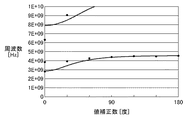
図4は、図2に示した電磁バンドギャップ構造体の変形例である。図4に示す電磁バンドギャップ構造体では、横方向の導体パッチ1間にギャップがなく、導体パッチ1が繋がっている。すなわち、導体パッチ1とグランド導体2により平行平板が構成されている。このときの等価回路は、図3における直列キャパシタンス32のない回路で表される。図5は、図4における並列素子の合成アドミタンスの10GHz以下の周波数特性であり、ショートスタブの長さが5mm、オープンスタブの長さが7mmのときの計算値である。合成アドミタンスが3GHz以下と5GHzから8GHzの周波数範囲では誘導性、合成アドミタンスが3GHzから5GHzの周波数範囲と8GHz以上において容量性を示す。
FIG. 4 is a modification of the electromagnetic bandgap structure shown in FIG. In the electromagnetic band gap structure shown in FIG. 4, there is no gap between the
図6は、本実施形態における電磁バンドギャップ構造体の単位セル分散特性を示す。図6において、実線はショートスタブ5mm、オープンスタブが7mmのときの等価回路による計算値を示す。また、黒丸は電磁界解析による解析結果を示す。回路計算と解析のためのパラメータは、単位セル8のサイズ1.9x1.7.mm、ビア4の高さ0.06mm、ショートスタブ短絡ビア6の高さ0.4mm、ビア4およびショートスタブ短絡ビア6の直径0.25mm、隣接導体パッチ1の間隔0.1mm、ショートスタブ5およびオープンスタブ7の幅0.1mmである。また、誘電体3の誘電率を4.4とした。このとき、位相定数が0となる2.8GHz以下および4.6〜6.3GHzの周波数範囲でバンドギャップ(遮断領域)となる。
FIG. 6 shows unit cell dispersion characteristics of the electromagnetic bandgap structure in the present embodiment. In FIG. 6, the solid line shows the calculated value by the equivalent circuit when the short stub is 5 mm and the open stub is 7 mm. Also, black circles show the analysis results by electromagnetic field analysis. The parameters for circuit calculation and analysis are as follows:
以上、本実施形態によれば、単位セルにおいて2つの導体間の同じ層にショートスタブとオープンスタブを設けることにより、単位セルの小型化を実現することが可能となる。 As described above, according to the present embodiment, the unit cell can be downsized by providing the short stub and the open stub in the same layer between the two conductors in the unit cell.
なお、本実施形態では、電磁バンドギャップ構造に適用するスタブを、ショートスタブ5およびオープンスタブ7の2つとして説明しているが、2つ以上であれば何本でもよい。また、本実施形態では、ショートスタブ5とオープンスタブ7により構成されているが、ショートスタブを少なくとも1つ含めばよく、例えばショートスタブのみで構成してもよい。
In the present embodiment, the stub applied to the electromagnetic band gap structure is described as two, that is, the
また、ショートスタブ短絡ビア6はショート端としているが、導体パッチ1にクリアランスを設け、貫通ビアとしてもよい。また、図2では、ショートスタブ短絡ビア6はグランド導体2に接触しているが、パッチ導体1に接触するようにしてもよい。また、ショートスタブ5およびオープンスタブ7のレイアウトは図1と図2に示したものに限らず、所望の長さを有していれば、例えば蛇行形状や直線形状でもよい。また、ショートスタブ短絡ビア6の位置もオープンスタブ7とショートスタブ5の外周側、すなわち、グランド導体2内の外側周辺である必要はないが、オープンスタブ7とショートスタブ5の外周側に設けることで小型なレイアウトが可能である。この場合の等価回路は、図3における直列キャパシタンス32のない構成となる。また、ショートスタブ5およびオープンスタブ7の位置は本実施形態に限定されず、導体パッチ1とグランド導体2の外側に構成されてもよい。
Although the short stub short-circuit via 6 is a short end, a clearance may be provided in the
[第2実施形態]
本実施形態における電磁バンドギャップ構造体断面図は図1と同じである。また、図7は、図1中A-A’面における平面図である。各図において同一符号は第1実施形態と同一または相当箇所を表す。本実施形態における電磁バンドギャップ構造は、単位セル10が1次元または2次元に規則的に配列された構成である。それぞれの単位セル10は、導体パッチ1、グランド導体2、導体パッチ1とグランド導体2を充填する誘電体3、ビア4、ショートスタブ5、ショートスタブ短絡ビア6、及びオープンスタブ7から構成される。本実施形態による単位セル10は、異なる層にスタブが配置されている点で第1実施形態と異なる。
8
[Second Embodiment]
The cross-sectional view of the electromagnetic bandgap structure in this embodiment is the same as FIG. FIG. 7 is a plan view of the AA ′ plane in FIG. In each drawing, the same reference numerals denote the same or corresponding parts as those in the first embodiment. The electromagnetic bandgap structure in the present embodiment has a configuration in which
8
ビア4は、平板導体である導体パッチ1及びグランド導体2と電気的に接触し、ショートスタブ5およびオープンスタブ7の一端とも電気的に接触する。ショートスタブ短絡ビア6はショートスタブ5の他端およびグランド導体2と電気的に接触し、ショート端となる。オープンスタブ7の他端は他の金属部と接触せず、オープン端となる。なお、ショートスタブ短絡ビア6は図1のA-A’面に存在しないが、説明のため図7に点線で描画している。
The via 4 is in electrical contact with the
図8は、図1と図7中の点線枠で示す単位セル10の等価回路図である。図3と異なる箇所は、ショートスタブ5のリアクタンス95とオープンスタブ7のリアクタンス96が直列に構成されている点である。他は図3と同様の等価回路のため、説明を省略する。
FIG. 8 is an equivalent circuit diagram of the
以上、本実施形態によれば、単位セルにおいて2つの導体間の異なる層にショートスタブとオープンスタブを設けることにより、第1実施形態と同様に単位セルの小型化を実現することが可能となる。 As described above, according to the present embodiment, by providing the short stub and the open stub in different layers between the two conductors in the unit cell, it is possible to realize the downsizing of the unit cell as in the first embodiment. .
なお、本実施形態において各スタブは直列に接続されているが、異なる層にスタブを配置すればよく、例えば、各スタブが並列に接続される構成としてもよい。また、本実施形態の電磁バンドギャップ構造に適用するスタブを、ショートスタブ5およびオープンスタブ7の2つとして説明しているが、2つ以上であれば何本でもよい。また、本実施形態ではショートスタブ5とオープンスタブ7により構成されているが、オープンスタブのみまたはショートスタブのみで構成しても同様の効果が得られる。
In the present embodiment, the stubs are connected in series. However, the stubs may be arranged in different layers. For example, the stubs may be connected in parallel. Moreover, although the stub applied to the electromagnetic bandgap structure of this embodiment is demonstrated as two, the
また、図1と図7においてショートスタブ短絡ビア6はグランド導体2とショートスタブ5間の層間ビアを用いているが、貫通ビアでも同様の効果が得られる。その場合は、グランド導体2とショートスタブ5の層以外で導通しないようにクリアランスを設け、他の層のスタブはクリアランスを避けてレイアウトする。また、ショートスタブ5およびオープンスタブ7のレイアウトは図1と図7に示したものに限らず、所望の長さを有していれば、例えば蛇行形状や直線形状でもよい。
In FIGS. 1 and 7, the short stub short-circuit via 6 uses an interlayer via between the
以上、本実施形態によれば、単位セルにおいて2つの導体間の異なる層にショートスタブとオープンスタブを設けることにより、単位セルの小型化を実現することが可能となる。 As described above, according to the present embodiment, the unit cell can be reduced in size by providing the short stub and the open stub in different layers between the two conductors in the unit cell.
本発明は電磁バンドギャップ構造であり、回路基板のグランドや電流を阻止すべき箇所に本発明を適用することで不要な電磁波を遮断することが可能である。 The present invention has an electromagnetic bandgap structure, and unnecessary electromagnetic waves can be blocked by applying the present invention to the ground of a circuit board or a portion where current should be blocked.
1 導体パッチ
2 グランド導体
3 誘電体
4 ビア(連結導体)
5 ショートスタブ
6 ショートスタブ短絡ビア
7 オープンスタブ
8 単位セル
1
5
Claims (10)
前記第1の平板導体と前記第2の平板導体の間に位置し、前記第1の平板導体と電気的に接続し、前記第2の平板導体と接続しない端部を有する第1の連結導体と、
前記第1の平板導体と第2の平板導体を電気的に接続する第2の連結導体と、
前記第1の連結導体の端部と前記第2の連結導体を電気的に接続する第1の導体片と、
前記第1の平板導体と前記第2の平板導体の間に位置し、前記第2の連結導体と電気的に接続し、他端は解放されている第2の導体片と、
を含むことを特徴とする電磁バンドギャップ構造体を構成するセル。 A first flat plate conductor and a second flat plate conductor disposed opposite to each other;
A first connecting conductor located between the first flat conductor and the second flat conductor, having an end portion that is electrically connected to the first flat conductor and not connected to the second flat conductor. When,
A second connecting conductor for electrically connecting the first flat plate conductor and the second flat plate conductor;
A first conductor piece that electrically connects an end of the first connecting conductor and the second connecting conductor ;
A second conductor piece located between the first flat conductor and the second flat conductor, electrically connected to the second connecting conductor, the other end being open;
A cell constituting an electromagnetic bandgap structure characterized by comprising:
Priority Applications (2)
| Application Number | Priority Date | Filing Date | Title |
|---|---|---|---|
| JP2014013634A JP6278720B2 (en) | 2014-01-28 | 2014-01-28 | Cell and electromagnetic band gap structure |
| US14/593,196 US9865932B2 (en) | 2014-01-28 | 2015-01-09 | Cell and electromagnetic band-gap structure |
Applications Claiming Priority (1)
| Application Number | Priority Date | Filing Date | Title |
|---|---|---|---|
| JP2014013634A JP6278720B2 (en) | 2014-01-28 | 2014-01-28 | Cell and electromagnetic band gap structure |
Publications (3)
| Publication Number | Publication Date |
|---|---|
| JP2015142223A JP2015142223A (en) | 2015-08-03 |
| JP2015142223A5 JP2015142223A5 (en) | 2017-03-02 |
| JP6278720B2 true JP6278720B2 (en) | 2018-02-14 |
Family
ID=53679911
Family Applications (1)
| Application Number | Title | Priority Date | Filing Date |
|---|---|---|---|
| JP2014013634A Active JP6278720B2 (en) | 2014-01-28 | 2014-01-28 | Cell and electromagnetic band gap structure |
Country Status (2)
| Country | Link |
|---|---|
| US (1) | US9865932B2 (en) |
| JP (1) | JP6278720B2 (en) |
Families Citing this family (10)
| Publication number | Priority date | Publication date | Assignee | Title |
|---|---|---|---|---|
| US10068181B1 (en) | 2015-04-27 | 2018-09-04 | Rigetti & Co, Inc. | Microwave integrated quantum circuits with cap wafer and methods for making the same |
| US10651562B2 (en) | 2016-02-18 | 2020-05-12 | Nec Corporation | Frequency selective surface, antenna, wireless communication device, and radar device |
| JP6769925B2 (en) * | 2016-06-30 | 2020-10-14 | 京セラ株式会社 | Electromagnetic blocking structure, dielectric substrate and unit cell |
| US11276727B1 (en) | 2017-06-19 | 2022-03-15 | Rigetti & Co, Llc | Superconducting vias for routing electrical signals through substrates and their methods of manufacture |
| US11121301B1 (en) | 2017-06-19 | 2021-09-14 | Rigetti & Co, Inc. | Microwave integrated quantum circuits with cap wafers and their methods of manufacture |
| JP7071142B2 (en) | 2018-02-07 | 2022-05-18 | キヤノン株式会社 | Communication systems, communication devices and communication methods |
| CN108832303B (en) * | 2018-06-07 | 2019-11-15 | 西安电子科技大学 | A kind of frequency-selective surfaces that high angle is stable |
| JP7179574B2 (en) * | 2018-10-17 | 2022-11-29 | キヤノン株式会社 | Communication system and communication method |
| US11165149B2 (en) | 2020-01-30 | 2021-11-02 | Aptiv Technologies Limited | Electromagnetic band gap structure (EBG) |
| JP7433950B2 (en) | 2020-02-07 | 2024-02-20 | キヤノン株式会社 | Communication device, application program, communication device control method, provision method, and server |
Family Cites Families (12)
| Publication number | Priority date | Publication date | Assignee | Title |
|---|---|---|---|---|
| US6262495B1 (en) | 1998-03-30 | 2001-07-17 | The Regents Of The University Of California | Circuit and method for eliminating surface currents on metals |
| US6483481B1 (en) * | 2000-11-14 | 2002-11-19 | Hrl Laboratories, Llc | Textured surface having high electromagnetic impedance in multiple frequency bands |
| US6476771B1 (en) * | 2001-06-14 | 2002-11-05 | E-Tenna Corporation | Electrically thin multi-layer bandpass radome |
| US7136028B2 (en) * | 2004-08-27 | 2006-11-14 | Freescale Semiconductor, Inc. | Applications of a high impedance surface |
| KR100753830B1 (en) * | 2006-04-04 | 2007-08-31 | 한국전자통신연구원 | High impedance surface structure using artificial magnetic conductor, and antenna and electromagnetic device using the same structure |
| JP5380919B2 (en) * | 2008-06-24 | 2014-01-08 | 日本電気株式会社 | Waveguide structure and printed wiring board |
| JP5522042B2 (en) * | 2008-08-01 | 2014-06-18 | 日本電気株式会社 | Structure, printed circuit board, antenna, transmission line waveguide converter, array antenna, electronic device |
| JP5326649B2 (en) * | 2009-02-24 | 2013-10-30 | 日本電気株式会社 | Antenna, array antenna, printed circuit board, and electronic device using the same |
| CN102414920B (en) * | 2009-04-30 | 2016-06-08 | 日本电气株式会社 | Structure, printed panel, antenna, transmission line waveguide transducer, array antenna and electronic installation |
| KR101072591B1 (en) * | 2009-08-10 | 2011-10-11 | 삼성전기주식회사 | Electromagnetic interference noise reduction board using electromagnetic bandgap structure |
| JP5725013B2 (en) * | 2010-03-08 | 2015-05-27 | 日本電気株式会社 | Structure, wiring board, and method of manufacturing wiring board |
| JP5997561B2 (en) * | 2012-09-25 | 2016-09-28 | キヤノン株式会社 | Metamaterial |
-
2014
- 2014-01-28 JP JP2014013634A patent/JP6278720B2/en active Active
-
2015
- 2015-01-09 US US14/593,196 patent/US9865932B2/en active Active
Also Published As
| Publication number | Publication date |
|---|---|
| JP2015142223A (en) | 2015-08-03 |
| US9865932B2 (en) | 2018-01-09 |
| US20150214631A1 (en) | 2015-07-30 |
Similar Documents
| Publication | Publication Date | Title |
|---|---|---|
| JP6278720B2 (en) | Cell and electromagnetic band gap structure | |
| EP2415119B1 (en) | Wide band array antenna | |
| US20150357698A1 (en) | Wideband transition between a planar transmission line and a waveguide | |
| WO2012093603A1 (en) | Electromagnetic wave transmission sheet | |
| US9357633B2 (en) | Structure, wiring board, and method of manufacturing wiring board | |
| US9583818B2 (en) | Metamaterial | |
| JP2007221774A (en) | Plane type antenna | |
| JP2013157982A (en) | High-performance broad band antenna | |
| US10243265B2 (en) | Wide band array antenna | |
| JP6204747B2 (en) | Electromagnetic band gap device and electronic circuit | |
| JP2010016554A (en) | Ebg structure unit | |
| CN104798256B (en) | Antenna | |
| KR20130117226A (en) | Antenna using meta-material | |
| US10547115B2 (en) | Wire-plate antenna having a capacitive roof incorporating a slot between the feed probe and the short-circuit wire | |
| US9768505B2 (en) | MIMO antenna with no phase change | |
| EP3007272A1 (en) | Ebg structure | |
| Palreddy et al. | Performance of spiral antenna over broadband uniform-height progressive EBG surface | |
| WO2012139370A1 (en) | An artificial microstructure and a magnetic resonance metamaterial which the artificial microstructure is used for | |
| JP5504944B2 (en) | Antenna device | |
| WO2017164059A1 (en) | Antenna | |
| JP6178292B2 (en) | Antenna device | |
| JP6769925B2 (en) | Electromagnetic blocking structure, dielectric substrate and unit cell | |
| CN107425269B (en) | Multi-frequency common-caliber broadband radiator | |
| EP2755278A1 (en) | Antenna device | |
| US9385430B2 (en) | Broadband patch antenna |
Legal Events
| Date | Code | Title | Description |
|---|---|---|---|
| A521 | Request for written amendment filed |
Free format text: JAPANESE INTERMEDIATE CODE: A523 Effective date: 20170123 |
|
| A621 | Written request for application examination |
Free format text: JAPANESE INTERMEDIATE CODE: A621 Effective date: 20170123 |
|
| A977 | Report on retrieval |
Free format text: JAPANESE INTERMEDIATE CODE: A971007 Effective date: 20171214 |
|
| TRDD | Decision of grant or rejection written | ||
| A01 | Written decision to grant a patent or to grant a registration (utility model) |
Free format text: JAPANESE INTERMEDIATE CODE: A01 Effective date: 20171219 |
|
| A61 | First payment of annual fees (during grant procedure) |
Free format text: JAPANESE INTERMEDIATE CODE: A61 Effective date: 20180116 |
|
| R151 | Written notification of patent or utility model registration |
Ref document number: 6278720 Country of ref document: JP Free format text: JAPANESE INTERMEDIATE CODE: R151 |