JP6277185B2 - Rotary cutting tool and reversible cutting insert - Google Patents
Rotary cutting tool and reversible cutting insert Download PDFInfo
- Publication number
- JP6277185B2 JP6277185B2 JP2015519485A JP2015519485A JP6277185B2 JP 6277185 B2 JP6277185 B2 JP 6277185B2 JP 2015519485 A JP2015519485 A JP 2015519485A JP 2015519485 A JP2015519485 A JP 2015519485A JP 6277185 B2 JP6277185 B2 JP 6277185B2
- Authority
- JP
- Japan
- Prior art keywords
- cutting
- corner
- insert
- cutting edge
- edge
- Prior art date
- Legal status (The legal status is an assumption and is not a legal conclusion. Google has not performed a legal analysis and makes no representation as to the accuracy of the status listed.)
- Active
Links
- 238000005520 cutting process Methods 0.000 title claims description 250
- 230000002441 reversible effect Effects 0.000 title claims description 11
- 230000002093 peripheral effect Effects 0.000 claims description 20
- 238000003801 milling Methods 0.000 claims description 16
- 238000007907 direct compression Methods 0.000 description 1
- 238000004519 manufacturing process Methods 0.000 description 1
- 229910052751 metal Inorganic materials 0.000 description 1
- 239000002184 metal Substances 0.000 description 1
- 238000012986 modification Methods 0.000 description 1
- 230000004048 modification Effects 0.000 description 1
- 238000000465 moulding Methods 0.000 description 1
- 238000005245 sintering Methods 0.000 description 1
- UONOETXJSWQNOL-UHFFFAOYSA-N tungsten carbide Chemical compound [W+]#[C-] UONOETXJSWQNOL-UHFFFAOYSA-N 0.000 description 1
Images


Classifications
-
- B—PERFORMING OPERATIONS; TRANSPORTING
- B23—MACHINE TOOLS; METAL-WORKING NOT OTHERWISE PROVIDED FOR
- B23B—TURNING; BORING
- B23B5/00—Turning-machines or devices specially adapted for particular work; Accessories specially adapted therefor
- B23B5/18—Turning-machines or devices specially adapted for particular work; Accessories specially adapted therefor for turning crankshafts, eccentrics, or cams, e.g. crankpin lathes
- B23B5/20—Turning-machines or devices specially adapted for particular work; Accessories specially adapted therefor for turning crankshafts, eccentrics, or cams, e.g. crankpin lathes without removing same from the engine
-
- B—PERFORMING OPERATIONS; TRANSPORTING
- B23—MACHINE TOOLS; METAL-WORKING NOT OTHERWISE PROVIDED FOR
- B23C—MILLING
- B23C5/00—Milling-cutters
- B23C5/02—Milling-cutters characterised by the shape of the cutter
- B23C5/06—Face-milling cutters, i.e. having only or primarily a substantially flat cutting surface
-
- B—PERFORMING OPERATIONS; TRANSPORTING
- B23—MACHINE TOOLS; METAL-WORKING NOT OTHERWISE PROVIDED FOR
- B23C—MILLING
- B23C5/00—Milling-cutters
- B23C5/16—Milling-cutters characterised by physical features other than shape
- B23C5/20—Milling-cutters characterised by physical features other than shape with removable cutter bits or teeth or cutting inserts
- B23C5/202—Plate-like cutting inserts with special form
-
- B—PERFORMING OPERATIONS; TRANSPORTING
- B23—MACHINE TOOLS; METAL-WORKING NOT OTHERWISE PROVIDED FOR
- B23B—TURNING; BORING
- B23B2200/00—Details of cutting inserts
- B23B2200/36—Other features of cutting inserts not covered by B23B2200/04 - B23B2200/32
- B23B2200/3681—Split inserts, i.e. comprising two or more sections roughly equal in size and having similar or dissimilar cutting geometries
-
- B—PERFORMING OPERATIONS; TRANSPORTING
- B23—MACHINE TOOLS; METAL-WORKING NOT OTHERWISE PROVIDED FOR
- B23C—MILLING
- B23C2200/00—Details of milling cutting inserts
- B23C2200/04—Overall shape
- B23C2200/0477—Triangular
-
- B—PERFORMING OPERATIONS; TRANSPORTING
- B23—MACHINE TOOLS; METAL-WORKING NOT OTHERWISE PROVIDED FOR
- B23C—MILLING
- B23C2200/00—Details of milling cutting inserts
- B23C2200/12—Side or flank surfaces
- B23C2200/123—Side or flank surfaces curved
-
- B—PERFORMING OPERATIONS; TRANSPORTING
- B23—MACHINE TOOLS; METAL-WORKING NOT OTHERWISE PROVIDED FOR
- B23C—MILLING
- B23C2200/00—Details of milling cutting inserts
- B23C2200/20—Top or side views of the cutting edge
- B23C2200/201—Details of the nose radius and immediately surrounding areas
-
- B—PERFORMING OPERATIONS; TRANSPORTING
- B23—MACHINE TOOLS; METAL-WORKING NOT OTHERWISE PROVIDED FOR
- B23C—MILLING
- B23C2200/00—Details of milling cutting inserts
- B23C2200/20—Top or side views of the cutting edge
- B23C2200/208—Wiper, i.e. an auxiliary cutting edge to improve surface finish
-
- B—PERFORMING OPERATIONS; TRANSPORTING
- B23—MACHINE TOOLS; METAL-WORKING NOT OTHERWISE PROVIDED FOR
- B23C—MILLING
- B23C2200/00—Details of milling cutting inserts
- B23C2200/28—Angles
- B23C2200/286—Positive cutting angles
-
- B—PERFORMING OPERATIONS; TRANSPORTING
- B23—MACHINE TOOLS; METAL-WORKING NOT OTHERWISE PROVIDED FOR
- B23C—MILLING
- B23C2200/00—Details of milling cutting inserts
- B23C2200/28—Angles
- B23C2200/287—Positive rake angles
-
- Y—GENERAL TAGGING OF NEW TECHNOLOGICAL DEVELOPMENTS; GENERAL TAGGING OF CROSS-SECTIONAL TECHNOLOGIES SPANNING OVER SEVERAL SECTIONS OF THE IPC; TECHNICAL SUBJECTS COVERED BY FORMER USPC CROSS-REFERENCE ART COLLECTIONS [XRACs] AND DIGESTS
- Y10—TECHNICAL SUBJECTS COVERED BY FORMER USPC
- Y10T—TECHNICAL SUBJECTS COVERED BY FORMER US CLASSIFICATION
- Y10T407/00—Cutters, for shaping
- Y10T407/19—Rotary cutting tool
- Y10T407/1906—Rotary cutting tool including holder [i.e., head] having seat for inserted tool
- Y10T407/1908—Face or end mill
- Y10T407/1924—Specified tool shape
-
- Y—GENERAL TAGGING OF NEW TECHNOLOGICAL DEVELOPMENTS; GENERAL TAGGING OF CROSS-SECTIONAL TECHNOLOGIES SPANNING OVER SEVERAL SECTIONS OF THE IPC; TECHNICAL SUBJECTS COVERED BY FORMER USPC CROSS-REFERENCE ART COLLECTIONS [XRACs] AND DIGESTS
- Y10—TECHNICAL SUBJECTS COVERED BY FORMER USPC
- Y10T—TECHNICAL SUBJECTS COVERED BY FORMER US CLASSIFICATION
- Y10T407/00—Cutters, for shaping
- Y10T407/23—Cutters, for shaping including tool having plural alternatively usable cutting edges
Description
発明の分野
本発明は、概して金属切削プロセスで使用するための切削インサートおよび切削工具に関し、詳細にはフライス作業用のリバーシブル切削インサートを有する回転切削工具に関する。
The present invention relates generally to cutting inserts and cutting tools for use in metal cutting processes, and more particularly to rotary cutting tools having reversible cutting inserts for milling operations.
発明の背景
フライス作業で使用される回転切削工具の分野内で、リバーシブル切削インサートの多くの例は、切削本体に取外し可能に固定される。いくつかの例では、これら切削工具は、直角の肩を削るフライス作業(square shoulder milling operations)を実行するように構成される。
BACKGROUND OF THE INVENTION Within the field of rotary cutting tools used in milling operations, many examples of reversible cutting inserts are removably secured to a cutting body. In some examples, these cutting tools are configured to perform square shoulder milling operations.
米国特許第7,241,082号は、全体的に長方形の割出し可能な両面切削インサートを開示し、この切削インサートは、2つの反対側の端面に接続された2つの主側面および2つの副側面と、合計4つの主切れ刃とを有する。各主切れ刃に隣接する主要な「逆転された」逃げ面は、急な内角で切削インサートの正中面に対して傾斜される。切削インサートはフライスのインサートポケット内に保持され、正の軸方向すくい角でフライス作業を実行するように構成される。 U.S. Pat. No. 7,241,082 discloses a generally rectangular indexable double-sided cutting insert that has two major sides and two secondary sides connected to two opposite end faces. It has a side surface and a total of four main cutting edges. The main “reversed” flank surface adjacent to each main cutting edge is inclined with respect to the median surface of the cutting insert with a steep interior angle. The cutting insert is held in the insert pocket of the milling cutter and is configured to perform the milling operation with a positive axial rake angle.
米国特許第7,455,483号は、「負」の形状の三角形の割出し可能な両面切削インサートを開示し、この切削インサートは、2つの反対の側に接続された6つのエッジ面と、合計6つの主切れ刃とを有する。切削インサートはフライス工具のインサートポケット内に配置され、正のすくい角で工作物に垂直なコーナーを切削するように構成される。 U.S. Pat. No. 7,455,483 discloses a "negative" shaped triangular indexable double-sided cutting insert that includes six edge surfaces connected to two opposite sides; It has a total of 6 main cutting edges. The cutting insert is disposed in the insert pocket of the milling tool and is configured to cut a corner perpendicular to the workpiece with a positive rake angle.
米国特許第7,604,441号は、「負」の形状の正方形の割出し可能な両面切削インサートを開示し、この切削インサートは、2つの反対側の端面に接続された4つの側面と、合計8つの主要切れ刃とを有する。切削インサートは、フライスのインサートポケット内に配置され、正の軸方向すくい角で工作物に真に90°の肩を切削するように構成される。しかしながら、肩の深さは、インサートの寸法によって、および主要切れ刃の長さに依存して制限される。 U.S. Patent No. 7,604,441 discloses a "negative" shaped square indexable double-sided cutting insert, which has four sides connected to two opposite end faces; It has a total of 8 main cutting edges. The cutting insert is placed in the insert pocket of the milling cutter and is configured to cut a true 90 ° shoulder into the workpiece with a positive axial rake angle. However, the depth of the shoulder is limited by the dimensions of the insert and depending on the length of the main cutting edge.
改良された切削インサートおよび切削工具を提供することが本発明の目的である。 It is an object of the present invention to provide an improved cutting insert and cutting tool.
側面当たり2つの主切れ刃を有する改良された切削インサートを提供することもまた本発明の目的である。 It is also an object of the present invention to provide an improved cutting insert having two main cutting edges per side.
頑丈な切れ刃を有する改良された切削インサートを提供することが本発明の別の目的である。 It is another object of the present invention to provide an improved cutting insert having a sturdy cutting edge.
直角の肩を削るフライス作業を実行できる改良された切削工具を提供することが本発明のさらに別の目的である。 It is yet another object of the present invention to provide an improved cutting tool that can perform a milling operation that cuts a right shoulder.
ランピング作業を実行できる改良された切削工具を提供することが本発明のなおさらに別の目的である。 It is yet another object of the present invention to provide an improved cutting tool that can perform a ramping operation.
発明の概要
本発明の1つの態様によれば、リバーシブルの割出し可能な切削インサートが提供され、切削インサートは、
連続周囲面によって相互に接続される反対側の第1および第2の端面であって、正中面が第1および第2の端面の間に配置され、周囲面と交差してインサート境界線を形成する第1および第2の端面と、正中面に対し垂直なインサート軸であってその周りで切削インサートが割出し可能なインサート軸と、を含み、
周囲面は、少なくとも3つのコーナー面と交互に存在する少なくとも3つの側面を含み、各コーナー面はインサート軸を含むコーナー二等分面を有し、
側面およびコーナー面は、それぞれ側縁部およびコーナー縁部で、第1および第2の端面の両方と交差し、各側縁部は主切れ刃を有し、および各コーナー縁部はコーナー切れ刃および副切れ刃を有し、
切削インサートの側面図において、各主切れ刃および副切れ刃は、その相互に関連するコーナー切れ刃のそれぞれ第1の終点および第2の終点から、正中面に向かって傾斜し、
正中面に対し垂直に延在し、かつコーナー切れ刃のいずれか1つと、第2の終点を除くその長さに沿ったいずれかの点で交差する第1の仮想直線が、インサート境界線の内側で正中面を通過する。
SUMMARY OF THE INVENTION According to one aspect of the present invention, a reversible indexable cutting insert is provided, the cutting insert comprising:
Opposite first and second end surfaces connected to each other by a continuous peripheral surface, the median surface being disposed between the first and second end surfaces and intersecting the peripheral surface to form an insert boundary line First and second end surfaces, and an insert shaft that is perpendicular to the median surface and into which a cutting insert can be indexed,
The peripheral surface includes at least three side surfaces alternating with at least three corner surfaces, each corner surface having a corner bisection surface including an insert axis;
The side and corner surfaces intersect the first and second end surfaces at the side edges and corner edges, respectively, each side edge has a main cutting edge, and each corner edge is a corner cutting edge And having a secondary cutting edge,
In the side view of the cutting insert, each primary cutting edge and secondary cutting edge is inclined from the first end point and the second end point, respectively, of its associated corner cutting edge toward the median plane,
A first imaginary straight line extending perpendicular to the median plane and intersecting any one of the corner cutting edges at any point along its length excluding the second end point is an insert boundary line Pass the median plane on the inside.
本発明の別の態様によれば、工具軸の周りを回転可能な切削工具が提供され、切削工具は、インサート受入れポケットを有する切削本体と、インサート受入れポケットの中に取外し可能に固定される、上に記載した種類の少なくとも1つのリバーシブルの割出し可能な切削インサートとを含む。
According to another aspect of the present invention, a cutting tool is provided that is rotatable about a tool axis, the cutting tool being removably secured within a cutting body having an insert receiving pocket and the insert receiving pocket. And at least one reversible indexable cutting insert of the type described above.
図面の簡単な説明
より深く理解するために、次に本発明を単なる例として添付の図面を参照して記載する。図面中、鎖線は部材を部分的に見るために切り取られた境界を表す。
BRIEF DESCRIPTION OF THE DRAWINGS For a better understanding, the present invention will now be described by way of example only with reference to the accompanying drawings. In the drawing, the chain line represents a boundary cut out to partially view the member.
発明の詳細な記載
本発明は、連続周囲面24によって相互に接続される反対側の第1および第2端面22を有するリバーシブルの割出し可能な切削インサート20に関し、周囲面24、少なくとも3つのコーナー面28と交互に存在する少なくとも3つの側面26。
DETAILED DESCRIPTION OF THE INVENTION The present invention relates to a reversible indexable cutting insert 20 having opposite first and
本発明のいくつかの実施形態では、少なくとも3つの側面26は同一であってもよく、少なくとも3つのコーナー面28は同一であってもよい。
In some embodiments of the present invention, at least three
図1および2aに示されるように、切削インサート20は規則的多角形の基本形状を有し得る。
As shown in FIGS. 1 and 2a, the
本発明のいくつかの実施形態では、切削インサート20は好ましくは、タングステンカーバイドなどの超硬合金を成形圧縮し焼結することによって製造され、コーティングされてもされなくてもよい。
In some embodiments of the present invention, the
図3および4に示されるように、切削インサート20は正中面Mを有し、正中面Mは、第1および第2端面22の間に位置付けられ、かつ周囲面24を分割しインサート境界線Lbを形成する。
As shown in FIGS. 3 and 4, the
本発明のいくつかの実施形態では、第1および第2端面22は同一であってもよく、それぞれ正中面Mと実質的に平行な支持面30を有する。
In some embodiments of the present invention, the first and
また、本発明のいくつかの実施形態では、2つの支持面30は、正中面Mから等距離であってもよい。
Also, in some embodiments of the present invention, the two
図3および4に示されるように、少なくとも3つの側面26およびコーナー面28は、それぞれ側部中間領域32およびコーナー部中間領域34を有してもよく、それらは正中面Mに対して垂直に延在する連続周囲中間領域36を形成する。
As shown in FIGS. 3 and 4, at least three
本記載を通して、正中面Mに対する周囲中間領域36の垂直度は0.5°の製造公差を有することを認識されたい。
Throughout this description, it will be appreciated that the perpendicularity of the peripheral
本発明のいくつかの実施形態では、周囲中間領域36は正中面Mの周りで鏡面対称を示し得る。
In some embodiments of the present invention, the
また、本発明のいくつかの実施形態では、側部中間領域32はそれぞれ平坦であってもよい。
Also, in some embodiments of the present invention, the side
図1および2aに示されるように、切削インサート20は、正中面Mに対して垂直なインサート軸A1であって、その周りで切削インサート20が割出し可能であるインサート軸A1を有する。
As shown in FIGS. 1 and 2a, the
本発明のいくつかの実施形態では、周囲面24は、ちょうど3つのコーナー面28と交互に存在するちょうど3つの側面26を有してもよく、切削インサート20はインサート軸A1の周りで3回回転対称を示してもよい。
In some embodiments of the present invention, the
同じく本発明のいくつかの実施形態では、インサート軸A1と同軸の貫通穴38が、第1および第2端面22の間に延在し、かつその両方で開口してもよい。
Similarly, in some embodiments of the present invention, a
図1および2aに示されるように、切削インサート20は、等辺三角形の基本形状を有し得る。
As shown in FIGS. 1 and 2a, the
本発明のいくつかの実施形態では、切削インサート20は、インサート軸A1の方向に沿って直接圧縮することによって製造されてもよい。
In some embodiments of the present invention, the
また、本発明のいくつかの実施形態では、切削インサート20は、その最終形状に圧縮されてもよく、周囲面24は研削されなくてもよい。
Also, in some embodiments of the present invention, the
本発明によれば、側面26およびコーナー面28は、それぞれ側縁部40およびコーナー縁部42で第1および第2端面22の両方と交差し、各側縁部40は主切れ刃44を有し、各コーナー縁部42はコーナー切れ刃46および副切れ刃48を有する。
According to the present invention, the
従って切削インサート20は、側面26あたり2つの主切れ刃44と、コーナー面28あたり2つのコーナー切れ刃46および副切れ刃48とを備えて有利には構成され、従ってインサート軸A1の周りで3回回転対称を示す実施形態では、切削インサート20は、合計6つの主切れ刃44、コーナー切れ刃46および副切れ刃48を有する。
Accordingly, the cutting
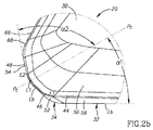
切削インサート20の端面視において、図2bに示されるように、各コーナー切れ刃46は湾曲してもよく、その一方、副および主切れ刃44、48は真直ぐであってもよい。湾曲したコーナー切れ刃46のそれぞれは、関連する主切れ刃44の実質的に真直ぐな部分と融合する第1の終点E1と、関連する副切れ刃48の実質的に真直ぐな部分と融合する第2の終点E2との間に延在する。
In the end view of the cutting
切削インサート20のコーナー側面視において、図3に示されるように、各コーナー切れ刃46はここでも湾曲してもよく、その一方、副および主切れ刃44、48はここでも真直ぐであってもよい。
In the corner side view of the cutting
図4に示されるように、横軸A2が各側面26を横切って延在し得、各側面26は関連する横軸A2の周りで2回回転対称を示し得る。
As shown in FIG. 4, a transverse axis A2 can extend across each
本発明のいくつかの実施形態では、主切れ刃44のそれぞれは、インサート軸A1および関連する横軸A2を含む側面二等分面Psと交差し得る。これら実施形態では、主切れ刃44のそれぞれは、関連する側面26の周囲長さの半分を超える長さに沿って延在することを理解することができる。
In some embodiments of the present invention, each of the main cutting edges 44 may intersect a side bisector Ps that includes an insert axis A1 and an associated transverse axis A2. In these embodiments, it can be appreciated that each of the main cutting edges 44 extends along a length that is more than half of the perimeter of the associated
本発明によれば、図3のコーナー側面視に示されるように、各主切れ刃44および副切れ刃48は、その相互に関連するコーナー切れ刃46のそれぞれ第1の終点E1および第2の終点E2から正中面Mに向かって傾斜する。
According to the present invention, as shown in the side view of the corner of FIG. 3, each
本発明のいくつかの実施形態では、各主切れ刃44および副切れ刃48は、その相互に関連するコーナー切れ刃46からその長さ全体に沿って正中面Mに向かって傾斜してもよい。
In some embodiments of the present invention, each
また、本発明のいくつかの実施形態では、図3および5に示されるように、各コーナー切れ刃46は、支持面30のそれぞれより正中面Mから完全に遠くに配置されてもよい。
Also, in some embodiments of the present invention, as shown in FIGS. 3 and 5, each
さらに、本発明のいくつかの実施形態では、図6に示すように、各端面22は、各主切れ刃44に隣接してすくい面50を含んでもよく、各すくい面50は正中面Mの方に傾けられ、関連する支持面30と融合する。
Further, in some embodiments of the present invention, each end face 22 may include a
図2bおよび5に示されるように、正中面Mに対し垂直に延び、かつコーナー切れ刃46のいずれか1つと第2の終点E2を除くその長さに沿ったいずれかの点で交差する第1の仮想直線L1が、インサート境界線Lbの内側で正中面Mを通過する。
As shown in FIGS. 2 b and 5, the first extends perpendicularly to the median plane M and intersects any one of the
第1の仮想直線L1は、図2bに示されるように切削インサート20の端面視において点のように見えることを認識されたい。
It should be recognized that the first imaginary straight line L1 looks like a point in the end view of the cutting
同じように、図1、2aおよび2bから推測できるように、副切れ刃48を正中面Mに投影した端面視において、(投影は図示されない)各副切れ刃48はインサート境界線Lbと一致し得る。
Similarly, FIG. 1,2a As can be inferred from and 2b, the end view of the minor cutting edge 4 8 projected on the median plane M, (projections not shown) each
本発明のいくつかの実施形態では、図3に示されるように、各コーナー面28は、同じコーナー中間領域34から両方の軸方向において各コーナー切れ刃46まで延在する2つの部分的に円錐状のコーナー逃げ面52を含み得る。図3のコーナー側面視で見られるように、2つの部分的に円錐状のコーナー逃げ面52は、切削インサート20の軸方向において重なり得る。
In some embodiments of the present invention, as shown in FIG. 3, each
インサート境界線Lbに対して、部分的に円錐状のコーナー逃げ面52(「逆転された」逃げ面としても知られる)のそれぞれは、関連するコーナー中間領域34から各コーナー切れ刃46に向かって内側に(すなわちインサート軸A1の方向に)全体的に延在し、その結果、各コーナー切れ刃46は有益に支持され、有利には頑丈であることを認識されたい。
Each of the partially conical corner flank surfaces 52 (also known as “reversed” flank surfaces) relative to the insert boundary line Lb is directed from the associated corner
本発明のいくつかの実施形態では、図3に示されるように、各コーナー面28は、同じコーナー中間領域34から両方の軸方向において各副切れ刃48まで延在する2つの平坦な副逃げ面54を含み得る。図3のコーナー側面視で見られるように、2つの平坦な副逃げ面54は切削インサート20の軸方向において重ならなくてもよい。
In some embodiments of the present invention, as shown in FIG. 3, each
また、本発明のいくつかの実施形態では、各副逃げ面54は正中面Mに対し垂直であり得る。
Also, in some embodiments of the present invention, each
さらに、本発明のいくつかの実施形態では、各副逃げ面54は、平坦でない接続面68によってその隣接する側面26から離間され得る。
Further, in some embodiments of the present invention, each
本発明によれば、図2aに示されるように、各コーナー面28は、インサート軸A1を含むコーナー二等分面Pcを有する。
According to the present invention, as shown in FIG. 2a, each
本発明のいくつかの実施形態では、各コーナー切れ刃46は、関連するコーナー二等分面Pcと交差し得、その第1および第2の終点E1、E2はコーナー二等分面Pcの反対側に配置され得る。しかしながら、図3のコーナー側面視で見られるように、コーナー二等分面Pcは、コーナー切れ刃46の最高地点を通過しなくてもよい。また、図2bの拡大端面視で見られるように、コーナー二等分面Pcはコーナー切れ刃46を二等分しなくてもよい(すなわち、その第1および第2の終点E1、E2の間の中間を通過する必要はない)。
In some embodiments of the invention, each
また、本発明のいくつかの実施形態では、図3に示されるように、各コーナー中間領域34は、関連するコーナー二等分面Pcの周りで鏡面対称を示し得る。
Also, in some embodiments of the present invention, as shown in FIG. 3, each corner
さらに、正中面Mに対し垂直な平坦な側部中間領域32を有する本発明の実施形態に関して、各側部中間領域32は、30°の値を有する、隣接コーナー面28のコーナー二等分面Pcとの第1の二等分角度α1を形成し得る。
Further, with respect to embodiments of the invention having flat side
なおさらに、正中面Mに対し垂直な平坦な副逃げ面54を有する本発明の実施形態に関して、各副逃げ面54は、60°〜80°の値を有する、関連するコーナー二等分面Pcとの第2の二等分角度α2を形成し得る。
Still further, with respect to embodiments of the invention having a flat
図6に示されるように、正中面Mに対し垂直に延び、かつ主切れ刃44のいずれか1つとその長さに沿ったいずれかの点で交差する第2の仮想直線L2は、インサート境界線Lbの内側で正中面Mを通過し得る。 As shown in FIG. 6, the second imaginary straight line L2 extending perpendicularly to the median plane M and intersecting any one of the main cutting edges 44 at any point along its length is an insert boundary. It can pass through the median plane M inside the line Lb.
本発明のいくつかの実施形態では、図4に示されるように、各側面26は、同じ側部中間領域32からそれらの各主切れ刃44まで延在する2つの主逃げ面56を含み得る。
In some embodiments of the present invention, as shown in FIG. 4, each
さらに、本発明のいくつかの実施形態では、各主切れ刃44は、その長さ全体に沿って実質的に直線であり得、各主逃げ面56は実質的に平坦であり得る。
Further, in some embodiments of the present invention, each
インサート境界線Lbに対して、主逃げ面56(「逆転された」逃げ面としても知られる)のそれぞれは、関連する側部中間領域32からその各主切れ刃44に向かって内側に(すなわちインサート軸A1の方向に)全体的に延在し、その結果、各主切れ刃44は有益に支持され、有利には頑丈であることを認識されたい。。
With respect to the insert boundary line Lb, each of the main flank surfaces 56 (also known as “reversed” flank surfaces) is inward from the associated side
図7〜10に示されるように、本発明は切削工具58にも関し、切削工具58は、工具軸A3の周りを回転方向Zに回転可能であり、切削本体60と、上記のリバーシブル割出し可能切削インサート20の少なくとも1つとを有する。各切削インサート20は切削本体60のインサート受入れポケット62に取外し可能に固定される。
As shown in FIGS. 7 to 10, the present invention also relates to a
本発明のいくつかの実施形態では、各切削インサート20は、締結ねじ64によってインサート受入れポケット62の中に取外し可能に固定することができ、締結ねじ64は、貫通穴38を通過しインサート受入れポケット62の座面(不図示)のねじ穴(不図示)とねじ係合する。
In some embodiments of the present invention, each cutting
図10に示されるように、各切削インサート20は、切削工具58がその回転軸A3の周りで回転する間、稼働するコーナー切れ刃46が、工具軸A3を含む半径方向面Prに円弧状の第1の外形線C1を刻み込み、この時、第1の外形線C1は、90°のコーナー切削角度δに対して一定の曲率半径Rを有するように切削工具58内で構成されることができる。
As shown in FIG. 10, each cutting
また、図10に示されるように、各切削インサート20は、切削工具58がその回転軸A3の周りで回転する間、稼働する主切れ刃44および副切れ刃48が、それぞれ直線状の第2の外形線C2および第3の外形線C3を、半径方向面Prに刻み込み、この時、第2の外形線C2は工具軸A3と実質的に平行であり、また、第3の外形線C3は工具軸A3と実質的に垂直であるように切削工具58内で構成されることができる。
Further, as shown in FIG. 10, each cutting
本記載を通して、第2および第3の外形線C2、C3の工具軸A3に対するそれぞれ平行度および垂直度は0.5°の精度誤差を有することを認識されたい。 Throughout this description, it should be appreciated that the parallelism and perpendicularity of the second and third contours C2, C3 with respect to the tool axis A3 have an accuracy error of 0.5 °, respectively.
本発明のいくつかの実施形態では、回転切削工具58はフライス作業に使用することができる。
In some embodiments of the present invention, the
フライス作業の間、稼働するコーナー切れ刃46は、90°のコーナー切削角度δに対して一定の曲率半径Rを有する工作物(不図示)のコーナーを切削し、その結果、有利にはコーナーに低減された応力集中がもたらされ、従って破壊の危険性が最小化されることを認識されたい。
During the milling operation, the operating
フライス作業の間、稼働する副切れ刃48(ワイパと呼ぶこともできる)は、工作物の表面に対し平行であり、平らで滑らかな表面仕上げを促進することも認識されたい。 It should also be appreciated that the secondary cutting edge 48 (which can also be referred to as a wiper) that is active during milling is parallel to the surface of the workpiece and promotes a flat and smooth surface finish.
フライス作業の間、「逆転された」主逃げ面56は、各リバーシブル切削インサート20の後続する稼働していない主切れ刃44に、工作物からのより大きい隙間を有益に提供し、従って比較的より小さい直径の切削工具58にそれらを配置することが有利には可能になることをさらに認識されたい。
During the milling operation, the “reversed”
本発明のいくつかの実施形態では、図10から容易に理解できるように、各切削インサート20は、稼働する主切れ刃44、コーナー切れ刃46、および副切れ刃48が、直角、すなわち90°の肩を削るフライス作業を工作物において実行するように、切削工具58内で構成されることができる。
In some embodiments of the present invention, each cutting
直角、すなわち90°の肩を削るフライス作業の間、機械加工される肩の高さは切削インサート20によって制限されないことを認識されたい。
It should be appreciated that during a milling operation that cuts a right angle, ie, 90 ° shoulder, the height of the machined shoulder is not limited by the cutting
本発明のいくつかの実施形態では、図8および9に示されるように、各切削インサート20は、稼働する主切れ刃44が正の軸方向すくい角βを有し、稼働する副切れ刃48が正の半径方向すくい角θを有するように、切削工具58内で構成されることができる。
In some embodiments of the present invention, as shown in FIGS. 8 and 9, each cutting
稼働する主切れ刃44および副切れ刃48にそれぞれ正の軸方向すくい角βおよび正の半径方向すくい角θを提供することによって、より低い切削力が発生され、機械スピンドルはより少ない作動力を必要とし、工作物はより滑らかな切削作用を受けることを認識されたい。また、生じる切屑は、稼働する切れ刃から有利には排出される。
By providing a positive axial rake angle β and a positive radial rake angle θ for the active
本発明のいくつかの実施形態では、各側縁部40は、関連する主切れ刃44から、隣接するコーナー縁部42に属する隣接する副切れ刃48に向かって延在する補助切れ刃66を含み得る。
In some embodiments of the invention, each
各切削インサート20は、稼働する副切れ刃48に属する補助切れ刃66が、ランピング作業の間稼働するように、切削工具58内で構成されることができる。
Each cutting
各切削インサート20は、稼働する主切れ刃44から延在する補助切れ刃66が、肩を削るフライス作業の間稼働する、従ってインサートの切削深さを増大するように、切削工具58内で構成されることもできる。
Each cutting
図3および4の側面視で見られるように、補助切れ刃66は、関連する主切れ刃44より少ない程度まで傾斜を付けることができる。いくつかの実施形態では、補助切れ刃66は正中面Mと平行であってもよい。
As can be seen in the side views of FIGS. 3 and 4, the
また、本発明のいくつかの実施形態では、各補助切れ刃66は、関連する支持面30と実質的に同一平面上にあってもよい。
Also, in some embodiments of the present invention, each
さらに、本発明のいくつかの実施形態では、各端面22は、ランピング作業の間、効果的な切屑排出を実現するために、各補助切れ刃66に隣接して長手方向に延在する補助すくい溝(不図示)を含んでもよい。
Further, in some embodiments of the present invention, each
本発明をある程度特異的に記載したが、以降で特許請求される本発明の趣旨および範囲から逸脱することなく様々な変更および修正を施すことができることは理解されよう。 While the invention has been described with a certain degree of particularity, it will be understood that various changes and modifications can be made without departing from the spirit and scope of the invention as claimed hereinafter.
Claims (22)
連続した周囲面(24)によって相互に接続される反対側の第1および第2の端面(22)であって、正中面(M)が、前記第1および第2の端面(22)の間に配置され、前記周囲面(24)と交差してインサート境界線(Lb)を形成する、第1および第2の端面(22)と、前記正中面(M)に対し垂直なインサート軸(A1)であってその周りで前記切削インサート(20)が割出し可能なインサート軸(A1)と、を含み、
前記周囲面(24)が、少なくとも3つのコーナー面(28)と交互に存在する少なくとも3つの側面(26)を含み、各コーナー面(28)が前記インサート軸(A1)を含むコーナー二等分面(Pc)を有し、
前記側面(26)およびコーナー面(28)が、それぞれ側縁部(40)およびコーナー縁部(42)で、前記第1および第2の端面(22)の両方と交差し、各側縁部(40)が主切れ刃(44)を有し、各コーナー縁部(42)がコーナー切れ刃(46)および副切れ刃(48)を有し、
前記切削インサート(20)の側面視において、各主切れ刃(44)および副切れ刃(48)が、その相互に関連するコーナー切れ刃(46)のそれぞれ第1の終点(E1)および第2の終点(E2)から、前記正中面(M)に向かって傾斜し、
前記正中面(M)に対し垂直に延在し、かつ前記コーナー切れ刃(46)のいずれか1つと、前記第2の終点(E2)を除くその長さに沿ったいずれかの点で交差する第1の仮想直線(L1)が、前記インサート境界線(Lb)の内側で前記正中面(M)を通過し、
前記切削インサート(20)の端面視において、前記切削インサート(20)が等辺三角形の基本形状を有する、リバーシブルの割出し可能な切削インサート(20)。 Reversible indexable cutting insert (20),
Opposite first and second end faces (22) connected to each other by a continuous peripheral face (24) , wherein the median face (M) is between the first and second end faces (22) arranged to form an insert border (Lb) intersects with said peripheral surface (24), first and second end surfaces (22), perpendicular to the insert axis relative to the median plane (M) (A1 And an insert shaft (A1) around which the cutting insert (20) can be indexed,
The peripheral surface (24) includes at least three side surfaces (26) alternating with at least three corner surfaces (28), and each corner surface (28) includes a corner bisection that includes the insert shaft (A1). Having a surface (Pc),
The side surface (26) and the corner surface (28) intersect with both the first and second end surfaces (22) at a side edge (40) and a corner edge (42), respectively, and each side edge (40) has a main cutting edge (44) and each corner edge (42) has a corner cutting edge (46) and a minor cutting edge (48);
In a side view of the cutting insert (20), each main cutting edge (44) and secondary cutting edge (48) has a first end point (E1) and a second end of the mutually related corner cutting edge (46), respectively. From the end point (E2) to the median plane (M),
Extends perpendicular to the median plane (M) and intersects any one of the corner cutting edges (46) at any point along its length except the second end point (E2) the first virtual straight line (L1) is passed through the median plane (M) inside said insert boundary line (Lb) which,
A reversible indexable cutting insert (20) in which the cutting insert (20) has a basic shape of an equilateral triangle in the end view of the cutting insert (20).
前記側部中間領域(32)およびコーナー中間領域(34)が、前記正中面(M)に対し垂直に延在する連続した周囲中間領域(36)を形成する、請求項1に記載の切削インサート(20)。 The at least three side surfaces (26) and corner surfaces (28) have side intermediate regions (32) and corner intermediate regions (34), respectively;
The side intermediate region (32) and the corner intermediate region (34) forms a continuous peripheral intermediate region extending perpendicularly to the median plane (M) (36), the cutting insert according to claim 1 (20).
前記第1の二等分角度(α1)が30°である、請求項4に記載の切削インサート(20)。 Each side intermediate region (32) forms a first bisector angle (α1) with said corner bisector (Pc) of an adjacent corner surface (28);
Cutting insert (20) according to claim 4, wherein the first bisecting angle (α1) is 30 °.
前記第2の二等分角度(α2)が60°〜80°である、請求項10に記載の切削インサート(20)。 Each minor flank (54) forms a second bisector angle (α2) with its associated corner bisector (Pc),
Cutting insert (20) according to claim 10, wherein the second bisecting angle (α2) is between 60 ° and 80 °.
その第1の終点(E1)および第2の終点(E2)が、前記コーナー二等分面(Pc)の反対側に配置される、請求項1〜11のいずれか一項に記載の切削インサート(20)。 Each corner cutting edge (46) intersects its associated corner bisector (Pc),
The cutting insert according to any one of claims 1 to 11, wherein the first end point (E1) and the second end point (E2) are arranged on the opposite side of the corner bisector (Pc). (20).
前記切削インサート(20)が前記インサート軸(A1)の周りで3回回転対称を示す、請求項1〜15のいずれか一項に記載の切削インサート(20)。 Said peripheral surface (24) has exactly three side surfaces (26) alternating with just three corner surfaces (28);
The cutting insert (20) according to any one of the preceding claims, wherein the cutting insert (20) exhibits a three-fold rotational symmetry about the insert axis (A1).
各側面(26)が、その関連する横軸(A2)の周りで2回回転対称を示す、請求項1〜16のいずれか一項に記載の切削インサート(20)。 A horizontal axis (A2) extends across each side (26);
Cutting insert (20) according to any one of the preceding claims, wherein each side (26) exhibits a two-fold rotational symmetry about its associated transverse axis (A2).
連続した周囲面(24)によって相互に接続される反対側の第1および第2の端面(22)であって、正中面(M)が、前記第1および第2の端面(22)の間に配置され、前記周囲面(24)と交差してインサート境界線(Lb)を形成する、第1および第2の端面(22)と、前記正中面(M)に対し垂直なインサート軸(A1)であってその周りで前記切削インサート(20)が割出し可能なインサート軸(A1)と、を含み、
前記周囲面(24)が、少なくとも3つのコーナー面(28)と交互に存在する少なくとも3つの側面(26)を含み、各コーナー面(28)が前記インサート軸(A1)を含むコーナー二等分面(Pc)を有し、
前記側面(26)およびコーナー面(28)が、それぞれ側縁部(40)およびコーナー縁部(42)で、前記第1および第2の端面(22)の両方と交差し、各側縁部(40)が主切れ刃(44)を有し、各コーナー縁部(42)がコーナー切れ刃(46)および副切れ刃(48)を有し、
前記切削インサート(20)の側面視において、各主切れ刃(44)および副切れ刃(48)が、その相互に関連するコーナー切れ刃(46)のそれぞれ第1の終点(E1)および第2の終点(E2)から、前記正中面(M)に向かって傾斜し、
前記正中面(M)に対し垂直に延在し、かつ前記コーナー切れ刃(46)のいずれか1つと、前記第2の終点(E2)を除くその長さに沿ったいずれかの点で交差する第1の仮想直線(L1)が、前記インサート境界線(Lb)の内側で前記正中面(M)を通過し、
各切削インサート(20)は、稼働する前記主切れ刃(44)が正の軸方向すくい角(β)を有し、稼働する前記副切れ刃(48)が正の半径方向すくい角(θ)を有するように構成される、切削工具(58)。 A cutting tool (58) rotatable about a tool axis (A3) comprising a cutting body (60) and at least one reversible indexable cutting insert (20), each cutting insert (20) Removably secured in the insert receiving pocket (62) of the cutting body (60), each cutting insert (20)
Opposite first and second end faces (22) connected to each other by a continuous peripheral face (24) , wherein the median face (M) is between the first and second end faces (22) arranged to form an insert border (Lb) intersects with said peripheral surface (24), first and second end surfaces (22), perpendicular to the insert axis relative to the median plane (M) (A1 And an insert shaft (A1) around which the cutting insert (20) can be indexed,
The peripheral surface (24) includes at least three side surfaces (26) alternating with at least three corner surfaces (28), and each corner surface (28) includes a corner bisection that includes the insert shaft (A1). Having a surface (Pc),
The side surface (26) and the corner surface (28) intersect with both the first and second end surfaces (22) at a side edge (40) and a corner edge (42), respectively, and each side edge (40) has a main cutting edge (44) and each corner edge (42) has a corner cutting edge (46) and a minor cutting edge (48);
In a side view of the cutting insert (20), each main cutting edge (44) and secondary cutting edge (48) has a first end point (E1) and a second end of the mutually related corner cutting edge (46), respectively. From the end point (E2) to the median plane (M),
Extends perpendicular to the median plane (M) and intersects any one of the corner cutting edges (46) at any point along its length except the second end point (E2) A first virtual straight line (L1) that passes through the median plane (M) inside the insert boundary line (Lb),
In each cutting insert (20), the operating main cutting edge (44) has a positive axial rake angle (β) and the operating secondary cutting edge (48) is a positive radial rake angle (θ). A cutting tool (58) configured to have:
各切削インサート(20)は、前記稼働する副切れ刃(48)に隣接する前記補助切れ刃(66)がランピング作業の間稼働するように構成される、請求項19または20に記載の切削工具(58)。 Auxiliary cutting edge (66) in which each side edge (40) extends from its associated main cutting edge (44) towards an adjacent secondary cutting edge (48) belonging to an adjacent corner cutting edge (42) Including
Cutting tool (20) according to claim 19 or 20 , wherein each cutting insert (20) is configured such that the auxiliary cutting edge (66) adjacent to the working secondary cutting edge (48) is activated during a ramping operation. (58).
前記第1外形線(C1)が、90°のコーナー切削角度(δ)に対して一定の曲率半径(R)を有する、請求項19〜21のいずれか一項に記載の切削工具(58)。
Each cutting insert (20) has a radial plane in which the corner cutting edge (46) operates while the cutting tool (58) rotates about its tool axis (A3), including the tool axis (A3). (Pr) is formed so as to engrave the arc-shaped first outline (C1),
Cutting tool (58) according to any one of claims 19 to 21 , wherein the first contour line (C1) has a constant radius of curvature (R) for a corner cutting angle (δ) of 90 °. .
Applications Claiming Priority (3)
| Application Number | Priority Date | Filing Date | Title |
|---|---|---|---|
| US13/542,846 US8708616B2 (en) | 2012-07-06 | 2012-07-06 | Rotary cutting tool and reversible cutting insert therefor |
| US13/542,846 | 2012-07-06 | ||
| PCT/IL2013/050492 WO2014006609A1 (en) | 2012-07-06 | 2013-06-09 | Rotary cutting tool and reversible cutting insert therefor |
Publications (3)
| Publication Number | Publication Date |
|---|---|
| JP2015521958A JP2015521958A (en) | 2015-08-03 |
| JP2015521958A5 JP2015521958A5 (en) | 2016-06-30 |
| JP6277185B2 true JP6277185B2 (en) | 2018-02-07 |
Family
ID=48782568
Family Applications (1)
| Application Number | Title | Priority Date | Filing Date |
|---|---|---|---|
| JP2015519485A Active JP6277185B2 (en) | 2012-07-06 | 2013-06-09 | Rotary cutting tool and reversible cutting insert |
Country Status (14)
| Country | Link |
|---|---|
| US (1) | US8708616B2 (en) |
| EP (1) | EP2869957B1 (en) |
| JP (1) | JP6277185B2 (en) |
| KR (1) | KR101887254B1 (en) |
| CN (1) | CN104395024B (en) |
| BR (1) | BR112014033023B1 (en) |
| CA (1) | CA2877602C (en) |
| DE (1) | DE112013003461T5 (en) |
| ES (1) | ES2813955T3 (en) |
| IL (1) | IL236299B (en) |
| PL (1) | PL2869957T3 (en) |
| PT (1) | PT2869957T (en) |
| RU (1) | RU2648717C2 (en) |
| WO (1) | WO2014006609A1 (en) |
Families Citing this family (44)
| Publication number | Priority date | Publication date | Assignee | Title |
|---|---|---|---|---|
| WO2011138950A1 (en) * | 2010-05-06 | 2011-11-10 | 株式会社タンガロイ | Cutting insert, and blade tip replacement type cutting tool |
| CN103889624B (en) * | 2011-10-31 | 2017-07-04 | 京瓷株式会社 | The manufacture method of cutting insert and cutting element and the machining thing using the cutting element |
| EP2740555B1 (en) * | 2012-12-07 | 2016-03-16 | Sandvik Tooling France | Cutting tool for face milling, corresponding method of face milling, cutting insert and tool body |
| JP6205726B2 (en) * | 2013-01-15 | 2017-10-04 | 三菱マテリアル株式会社 | Cutting inserts for face milling and exchangeable face milling |
| US20170197257A1 (en) * | 2013-12-25 | 2017-07-13 | Tungaloy Corporation | Indexable rotary cutting tool and tool body |
| USD746347S1 (en) * | 2013-12-27 | 2015-12-29 | Taegutec Ltd. | Cutting insert |
| USD746346S1 (en) * | 2013-12-27 | 2015-12-29 | Taegutec Ltd. | Cutting insert |
| AT14072U1 (en) * | 2014-02-04 | 2015-04-15 | Ceratizit Luxembourg S R L | Double-sided milling cutting insert and milling tool |
| USD744557S1 (en) * | 2014-05-12 | 2015-12-01 | Sumitomo Electric Hardmetal Corp. | Cutting insert |
| JP5979619B2 (en) | 2014-05-26 | 2016-08-24 | 株式会社タンガロイ | Cutting inserts, bodies and cutting tools |
| JP5888656B2 (en) * | 2014-06-02 | 2016-03-22 | 住友電工ハードメタル株式会社 | Cutting insert and milling cutter |
| JP6449581B2 (en) * | 2014-07-30 | 2019-01-09 | 京セラ株式会社 | Cutting insert and throwaway cutter |
| ES2913296T3 (en) | 2014-09-22 | 2022-06-01 | Iscar Ltd | Rotary cutting tool and reversible cutting insert having variable width minor relief surfaces therefor |
| US9468983B2 (en) | 2014-09-22 | 2016-10-18 | Iscar, Ltd. | Rotary cutting tool and reversible cutting insert having variable-width minor relief surfaces therefor |
| EP3072616B1 (en) * | 2015-03-25 | 2018-10-10 | Sandvik Intellectual Property AB | Cutting insert and milling tool |
| JP6470405B2 (en) * | 2015-05-26 | 2019-02-13 | 京セラ株式会社 | CUTTING INSERT, CUTTING TOOL, AND CUTTING PRODUCT MANUFACTURING METHOD USING THE SAME |
| USD778330S1 (en) | 2015-07-16 | 2017-02-07 | Kennametal Inc. | Double-sided tangential cutting insert |
| US9981323B2 (en) | 2015-07-16 | 2018-05-29 | Kennametal Inc. | Double-sided tangential cutting insert and cutting tool system using the same |
| USD777230S1 (en) | 2015-07-16 | 2017-01-24 | Kennametal Inc | Double-sided tangential cutting insert |
| EP3153260B1 (en) * | 2015-10-09 | 2018-05-23 | Sandvik Intellectual Property AB | Turning insert and method |
| WO2017068922A1 (en) * | 2015-10-19 | 2017-04-27 | 株式会社タンガロイ | Cutting insert and cutting tool |
| US10076795B2 (en) * | 2015-11-19 | 2018-09-18 | Iscar, Ltd. | Triangular tangential milling insert and milling tool |
| US10035199B2 (en) * | 2016-06-30 | 2018-07-31 | Iscar, Ltd. | Cutting tool and triangular-shaped indexable cutting insert therefor |
| JP6717941B2 (en) * | 2016-07-11 | 2020-07-08 | 京セラ株式会社 | Manufacturing method of cutting insert, cutting tool, and cut product |
| EP3338931A4 (en) * | 2016-09-27 | 2019-09-11 | Tungaloy Corporation | Cutting insert and cutting tool |
| JP6756082B2 (en) * | 2016-10-14 | 2020-09-16 | 住友電工ハードメタル株式会社 | Cutting insert |
| EP3315234A1 (en) * | 2016-10-25 | 2018-05-02 | Pramet Tools, S.R.O. | Metal cutting insert for milling |
| EP3338927B1 (en) * | 2016-12-22 | 2023-07-26 | Sandvik Intellectual Property AB | Cutting insert and shoulder milling tool |
| EP3338928B1 (en) * | 2016-12-22 | 2022-03-30 | Sandvik Intellectual Property AB | Cutting insert and shoulder milling tool |
| CN106735487B (en) * | 2016-12-28 | 2018-07-13 | 株洲华锐硬质合金工具有限责任公司 | Position rotatable blade for milling processing and process tool |
| EP3616814A4 (en) * | 2017-04-25 | 2021-01-20 | Sumitomo Electric Hardmetal Corp. | Cutting insert |
| CN107295907A (en) * | 2017-06-07 | 2017-10-27 | 江苏鼎钰生态农业科技有限公司 | A kind of blade in electric trimmer |
| TWI825040B (en) * | 2017-11-30 | 2023-12-11 | 以色列商艾斯卡公司 | Single-sided three-way indexable milling insert, tool holder and insert mill comprising the insert and the tool holder |
| TWI787381B (en) * | 2017-11-30 | 2022-12-21 | 以色列商艾斯卡公司 | Single-sided three-way indexable cutting insert and insert mill therefor |
| EP3542936A1 (en) * | 2018-03-22 | 2019-09-25 | AB Sandvik Coromant | A cutting insert for a shoulder milling tool |
| CN112512736B (en) | 2018-06-08 | 2023-10-10 | 株式会社Moldino | Cutting insert and indexable insert cutting tool |
| CN112543688A (en) * | 2018-08-30 | 2021-03-23 | 三菱综合材料株式会社 | Cutting insert and indexable cutting tool |
| DE112019005282T5 (en) * | 2018-10-23 | 2021-07-15 | Kyocera Corporation | CUTTING INSERT, CUTTING TOOL AND METHOD FOR MANUFACTURING A MACHINED PRODUCT |
| JP6744599B1 (en) * | 2019-03-01 | 2020-08-19 | 株式会社タンガロイ | Cutting insert |
| DE102020115987A1 (en) * | 2019-07-05 | 2021-01-07 | Kennametal India Limited | TWO-SIDED, POLYGONAL INDEXABLE INSERT WITH ALTERNATING CONCAVES AND CONVEX CUTTING EDGES |
| AT16933U1 (en) * | 2019-07-11 | 2020-12-15 | Ceratizit Austria Gmbh | Double-sided cutting insert for milling |
| DE102019123912A1 (en) | 2019-09-05 | 2021-03-11 | Kennametal Inc. | Cutting insert and cutting tool |
| JPWO2021193705A1 (en) * | 2020-03-25 | 2021-09-30 | ||
| JP7011689B1 (en) * | 2020-08-11 | 2022-01-27 | 株式会社タンガロイ | Cutting inserts and rotary cutting tools |
Family Cites Families (20)
| Publication number | Priority date | Publication date | Assignee | Title |
|---|---|---|---|---|
| US4318644A (en) * | 1980-07-07 | 1982-03-09 | Gte Products Corporation | Cutting insert |
| US4359300A (en) * | 1980-12-29 | 1982-11-16 | General Electric Co. | Cutting insert with improved chip control |
| US4411565A (en) * | 1981-05-08 | 1983-10-25 | General Electric Company | Finishing insert with improved chip control |
| US4618296A (en) * | 1983-09-14 | 1986-10-21 | Gte Valeron Corporation | Cutting tool and insert therefor |
| SU1505683A1 (en) * | 1987-06-04 | 1989-09-07 | Предприятие П/Я Г-4760 | Tool with exchangeable cutting bits |
| SE520997C2 (en) * | 2001-01-09 | 2003-09-23 | Sandvik Ab | Reversible cutter with grooved coupling surface against the holder and central material portion for fasteners |
| IL160223A (en) * | 2004-02-04 | 2008-11-26 | Carol Smilovici | Double-sided cutting insert and milling cutter |
| IL169491A (en) | 2005-06-30 | 2009-06-15 | Carol Smilovici | Cutting insert |
| SE529068C2 (en) | 2005-09-28 | 2007-04-24 | Seco Tools Ab | Milling inserts and milling tools |
| IL182100A (en) * | 2007-03-21 | 2010-11-30 | Taegutec India Ltd | Cutting insert for a milling cutter |
| KR101720332B1 (en) * | 2007-04-26 | 2017-03-27 | 태구텍 인디아 피. 엘티디. | Cutting insert for a milling cutter |
| EP2155425A1 (en) * | 2007-05-24 | 2010-02-24 | CeramTec AG | Cutting insert comprising a stabilising double-sided facet |
| US8491234B2 (en) * | 2009-02-12 | 2013-07-23 | TDY Industries, LLC | Double-sided cutting inserts for high feed milling |
| US7976250B2 (en) | 2009-02-12 | 2011-07-12 | Tdy Industries, Inc. | Double-sided cutting inserts for high feed milling |
| DE102009020373A1 (en) * | 2009-05-08 | 2010-11-11 | Kennametal Inc. | Cutter cutting insert |
| KR101097658B1 (en) * | 2009-05-29 | 2011-12-22 | 대구텍 유한회사 | Cutting insert |
| KR100939085B1 (en) * | 2009-07-15 | 2010-01-28 | 한국야금 주식회사 | Cutting insert |
| EP2394766A1 (en) * | 2010-06-10 | 2011-12-14 | Lamina Technologies SA | Double-sided indexable cutting insert and cutting tool |
| DE102011105978B4 (en) | 2011-06-29 | 2022-06-23 | Kennametal Inc. | Indexable insert and face milling cutter with indexable insert |
| US8573905B2 (en) * | 2012-03-22 | 2013-11-05 | Iscar, Ltd. | Triangular cutting insert and cutting tool |
-
2012
- 2012-07-06 US US13/542,846 patent/US8708616B2/en active Active
-
2013
- 2013-06-09 KR KR1020147036904A patent/KR101887254B1/en active IP Right Grant
- 2013-06-09 EP EP13735454.4A patent/EP2869957B1/en active Active
- 2013-06-09 BR BR112014033023-9A patent/BR112014033023B1/en active IP Right Grant
- 2013-06-09 PL PL13735454T patent/PL2869957T3/en unknown
- 2013-06-09 JP JP2015519485A patent/JP6277185B2/en active Active
- 2013-06-09 RU RU2015103929A patent/RU2648717C2/en active
- 2013-06-09 DE DE112013003461.1T patent/DE112013003461T5/en not_active Withdrawn
- 2013-06-09 CA CA2877602A patent/CA2877602C/en active Active
- 2013-06-09 CN CN201380035823.1A patent/CN104395024B/en active Active
- 2013-06-09 WO PCT/IL2013/050492 patent/WO2014006609A1/en active Application Filing
- 2013-06-09 ES ES13735454T patent/ES2813955T3/en active Active
- 2013-06-09 PT PT137354544T patent/PT2869957T/en unknown
-
2014
- 2014-12-16 IL IL236299A patent/IL236299B/en active IP Right Grant
Also Published As
| Publication number | Publication date |
|---|---|
| CA2877602A1 (en) | 2014-01-09 |
| BR112014033023B1 (en) | 2020-09-15 |
| KR20150030217A (en) | 2015-03-19 |
| ES2813955T3 (en) | 2021-03-25 |
| EP2869957A1 (en) | 2015-05-13 |
| PT2869957T (en) | 2020-10-07 |
| CA2877602C (en) | 2018-02-13 |
| IL236299B (en) | 2018-01-31 |
| RU2015103929A (en) | 2016-08-27 |
| KR101887254B1 (en) | 2018-08-09 |
| JP2015521958A (en) | 2015-08-03 |
| RU2648717C2 (en) | 2018-03-28 |
| US20140010605A1 (en) | 2014-01-09 |
| US8708616B2 (en) | 2014-04-29 |
| DE112013003461T5 (en) | 2015-03-26 |
| BR112014033023A2 (en) | 2017-06-27 |
| WO2014006609A1 (en) | 2014-01-09 |
| PL2869957T3 (en) | 2021-01-11 |
| CN104395024B (en) | 2017-09-12 |
| EP2869957B1 (en) | 2020-08-05 |
| CN104395024A (en) | 2015-03-04 |
| IL236299A0 (en) | 2015-02-26 |
Similar Documents
| Publication | Publication Date | Title |
|---|---|---|
| JP6277185B2 (en) | Rotary cutting tool and reversible cutting insert | |
| JP6590912B2 (en) | Rotating cutting tool and reversible cutting insert with variable width secondary flank for rotating cutting tool | |
| JP6146924B2 (en) | Cutting inserts and cutting tools | |
| JP5475808B2 (en) | Rotating tools and cutting inserts for cutting | |
| JP5848063B2 (en) | Turning inserts, turning tools and equipment | |
| JP6205726B2 (en) | Cutting inserts for face milling and exchangeable face milling | |
| WO2011092883A1 (en) | Cutting insert, cutting tool, and manufacturing method for cut product using same | |
| JP2015521958A5 (en) | ||
| WO2015080168A1 (en) | Cutting insert and replaceable cutting edge cutting tool | |
| EP2958696B1 (en) | Tangential ramping milling insert and high speed milling tool using such an insert | |
| EP2998053B1 (en) | Rotary cutting tool and reversible cutting insert having variable-width minor relief surfaces therefor | |
| JP2011093043A (en) | Cutting insert, cutting tool, and method of manufacturing workpiece to be cut | |
| JPH07237027A (en) | Throwaway tip and cutting tool | |
| WO2016080486A1 (en) | Cutting insert and cutting edge-replaceable rotary cutting tool | |
| JP6869492B2 (en) | Cutting insert | |
| JP6032513B2 (en) | Cutting inserts, tool bodies and cutting edge exchangeable rotary cutting tools |
Legal Events
| Date | Code | Title | Description |
|---|---|---|---|
| A521 | Request for written amendment filed |
Free format text: JAPANESE INTERMEDIATE CODE: A523 Effective date: 20160511 |
|
| A621 | Written request for application examination |
Free format text: JAPANESE INTERMEDIATE CODE: A621 Effective date: 20160511 |
|
| A977 | Report on retrieval |
Free format text: JAPANESE INTERMEDIATE CODE: A971007 Effective date: 20170315 |
|
| A131 | Notification of reasons for refusal |
Free format text: JAPANESE INTERMEDIATE CODE: A131 Effective date: 20170508 |
|
| A521 | Request for written amendment filed |
Free format text: JAPANESE INTERMEDIATE CODE: A523 Effective date: 20170711 |
|
| TRDD | Decision of grant or rejection written | ||
| A01 | Written decision to grant a patent or to grant a registration (utility model) |
Free format text: JAPANESE INTERMEDIATE CODE: A01 Effective date: 20180105 |
|
| A61 | First payment of annual fees (during grant procedure) |
Free format text: JAPANESE INTERMEDIATE CODE: A61 Effective date: 20180115 |
|
| R150 | Certificate of patent or registration of utility model |
Ref document number: 6277185 Country of ref document: JP Free format text: JAPANESE INTERMEDIATE CODE: R150 |
|
| R250 | Receipt of annual fees |
Free format text: JAPANESE INTERMEDIATE CODE: R250 |
|
| R250 | Receipt of annual fees |
Free format text: JAPANESE INTERMEDIATE CODE: R250 |
|
| R250 | Receipt of annual fees |
Free format text: JAPANESE INTERMEDIATE CODE: R250 |
|
| R250 | Receipt of annual fees |
Free format text: JAPANESE INTERMEDIATE CODE: R250 |