JP6273345B2 - Articulated surgical instrument - Google Patents
Articulated surgical instrument Download PDFInfo
- Publication number
- JP6273345B2 JP6273345B2 JP2016500334A JP2016500334A JP6273345B2 JP 6273345 B2 JP6273345 B2 JP 6273345B2 JP 2016500334 A JP2016500334 A JP 2016500334A JP 2016500334 A JP2016500334 A JP 2016500334A JP 6273345 B2 JP6273345 B2 JP 6273345B2
- Authority
- JP
- Japan
- Prior art keywords
- tubular member
- spine
- surgical instrument
- shaft assembly
- elongate shaft
- Prior art date
- Legal status (The legal status is an assumption and is not a legal conclusion. Google has not performed a legal analysis and makes no representation as to the accuracy of the status listed.)
- Active
Links
- 238000005452 bending Methods 0.000 claims description 89
- 230000033001 locomotion Effects 0.000 claims description 34
- 238000001356 surgical procedure Methods 0.000 claims description 2
- 230000007246 mechanism Effects 0.000 description 14
- 230000008878 coupling Effects 0.000 description 10
- 238000010168 coupling process Methods 0.000 description 10
- 238000005859 coupling reaction Methods 0.000 description 10
- 238000000034 method Methods 0.000 description 7
- 230000007935 neutral effect Effects 0.000 description 7
- 239000004744 fabric Substances 0.000 description 5
- 230000008439 repair process Effects 0.000 description 5
- 230000008901 benefit Effects 0.000 description 2
- 230000008859 change Effects 0.000 description 2
- 230000006835 compression Effects 0.000 description 2
- 238000007906 compression Methods 0.000 description 2
- 230000008602 contraction Effects 0.000 description 2
- 230000006870 function Effects 0.000 description 2
- 239000000463 material Substances 0.000 description 2
- 210000001519 tissue Anatomy 0.000 description 2
- 206010019909 Hernia Diseases 0.000 description 1
- 239000000853 adhesive Substances 0.000 description 1
- 230000001070 adhesive effect Effects 0.000 description 1
- 230000005540 biological transmission Effects 0.000 description 1
- 230000015572 biosynthetic process Effects 0.000 description 1
- 210000000988 bone and bone Anatomy 0.000 description 1
- 238000005219 brazing Methods 0.000 description 1
- 239000002131 composite material Substances 0.000 description 1
- 238000005520 cutting process Methods 0.000 description 1
- 238000006073 displacement reaction Methods 0.000 description 1
- 239000012636 effector Substances 0.000 description 1
- 239000002783 friction material Substances 0.000 description 1
- 238000000227 grinding Methods 0.000 description 1
- 238000003780 insertion Methods 0.000 description 1
- 230000037431 insertion Effects 0.000 description 1
- 230000003993 interaction Effects 0.000 description 1
- 238000002357 laparoscopic surgery Methods 0.000 description 1
- 238000003698 laser cutting Methods 0.000 description 1
- 238000005461 lubrication Methods 0.000 description 1
- 230000014759 maintenance of location Effects 0.000 description 1
- 238000003801 milling Methods 0.000 description 1
- 230000004048 modification Effects 0.000 description 1
- 238000012986 modification Methods 0.000 description 1
- 230000009467 reduction Effects 0.000 description 1
- 239000011435 rock Substances 0.000 description 1
- 238000005476 soldering Methods 0.000 description 1
- 230000007704 transition Effects 0.000 description 1
- XLYOFNOQVPJJNP-UHFFFAOYSA-N water Substances O XLYOFNOQVPJJNP-UHFFFAOYSA-N 0.000 description 1
- 238000003466 welding Methods 0.000 description 1
Images


Classifications
-
- A—HUMAN NECESSITIES
- A61—MEDICAL OR VETERINARY SCIENCE; HYGIENE
- A61B—DIAGNOSIS; SURGERY; IDENTIFICATION
- A61B17/00—Surgical instruments, devices or methods, e.g. tourniquets
- A61B17/00234—Surgical instruments, devices or methods, e.g. tourniquets for minimally invasive surgery
-
- A—HUMAN NECESSITIES
- A61—MEDICAL OR VETERINARY SCIENCE; HYGIENE
- A61B—DIAGNOSIS; SURGERY; IDENTIFICATION
- A61B17/00—Surgical instruments, devices or methods, e.g. tourniquets
- A61B17/068—Surgical staplers, e.g. containing multiple staples or clamps
-
- A—HUMAN NECESSITIES
- A61—MEDICAL OR VETERINARY SCIENCE; HYGIENE
- A61B—DIAGNOSIS; SURGERY; IDENTIFICATION
- A61B17/00—Surgical instruments, devices or methods, e.g. tourniquets
- A61B17/068—Surgical staplers, e.g. containing multiple staples or clamps
- A61B17/072—Surgical staplers, e.g. containing multiple staples or clamps for applying a row of staples in a single action, e.g. the staples being applied simultaneously
- A61B17/07207—Surgical staplers, e.g. containing multiple staples or clamps for applying a row of staples in a single action, e.g. the staples being applied simultaneously the staples being applied sequentially
-
- A—HUMAN NECESSITIES
- A61—MEDICAL OR VETERINARY SCIENCE; HYGIENE
- A61B—DIAGNOSIS; SURGERY; IDENTIFICATION
- A61B17/00—Surgical instruments, devices or methods, e.g. tourniquets
- A61B17/10—Surgical instruments, devices or methods, e.g. tourniquets for applying or removing wound clamps, e.g. containing only one clamp or staple; Wound clamp magazines
-
- A—HUMAN NECESSITIES
- A61—MEDICAL OR VETERINARY SCIENCE; HYGIENE
- A61B—DIAGNOSIS; SURGERY; IDENTIFICATION
- A61B17/00—Surgical instruments, devices or methods, e.g. tourniquets
- A61B17/28—Surgical forceps
- A61B17/29—Forceps for use in minimally invasive surgery
-
- A—HUMAN NECESSITIES
- A61—MEDICAL OR VETERINARY SCIENCE; HYGIENE
- A61F—FILTERS IMPLANTABLE INTO BLOOD VESSELS; PROSTHESES; DEVICES PROVIDING PATENCY TO, OR PREVENTING COLLAPSING OF, TUBULAR STRUCTURES OF THE BODY, e.g. STENTS; ORTHOPAEDIC, NURSING OR CONTRACEPTIVE DEVICES; FOMENTATION; TREATMENT OR PROTECTION OF EYES OR EARS; BANDAGES, DRESSINGS OR ABSORBENT PADS; FIRST-AID KITS
- A61F2/00—Filters implantable into blood vessels; Prostheses, i.e. artificial substitutes or replacements for parts of the body; Appliances for connecting them with the body; Devices providing patency to, or preventing collapsing of, tubular structures of the body, e.g. stents
- A61F2/0063—Implantable repair or support meshes, e.g. hernia meshes
-
- A—HUMAN NECESSITIES
- A61—MEDICAL OR VETERINARY SCIENCE; HYGIENE
- A61M—DEVICES FOR INTRODUCING MEDIA INTO, OR ONTO, THE BODY; DEVICES FOR TRANSDUCING BODY MEDIA OR FOR TAKING MEDIA FROM THE BODY; DEVICES FOR PRODUCING OR ENDING SLEEP OR STUPOR
- A61M25/00—Catheters; Hollow probes
- A61M25/01—Introducing, guiding, advancing, emplacing or holding catheters
- A61M25/0105—Steering means as part of the catheter or advancing means; Markers for positioning
- A61M25/0133—Tip steering devices
- A61M25/0138—Tip steering devices having flexible regions as a result of weakened outer material, e.g. slots, slits, cuts, joints or coils
-
- A—HUMAN NECESSITIES
- A61—MEDICAL OR VETERINARY SCIENCE; HYGIENE
- A61M—DEVICES FOR INTRODUCING MEDIA INTO, OR ONTO, THE BODY; DEVICES FOR TRANSDUCING BODY MEDIA OR FOR TAKING MEDIA FROM THE BODY; DEVICES FOR PRODUCING OR ENDING SLEEP OR STUPOR
- A61M25/00—Catheters; Hollow probes
- A61M25/01—Introducing, guiding, advancing, emplacing or holding catheters
- A61M25/0105—Steering means as part of the catheter or advancing means; Markers for positioning
- A61M25/0133—Tip steering devices
- A61M25/0147—Tip steering devices with movable mechanical means, e.g. pull wires
-
- A—HUMAN NECESSITIES
- A61—MEDICAL OR VETERINARY SCIENCE; HYGIENE
- A61B—DIAGNOSIS; SURGERY; IDENTIFICATION
- A61B1/00—Instruments for performing medical examinations of the interior of cavities or tubes of the body by visual or photographical inspection, e.g. endoscopes; Illuminating arrangements therefor
- A61B1/005—Flexible endoscopes
- A61B1/0051—Flexible endoscopes with controlled bending of insertion part
- A61B1/0052—Constructional details of control elements, e.g. handles
-
- A—HUMAN NECESSITIES
- A61—MEDICAL OR VETERINARY SCIENCE; HYGIENE
- A61B—DIAGNOSIS; SURGERY; IDENTIFICATION
- A61B17/00—Surgical instruments, devices or methods, e.g. tourniquets
- A61B17/04—Surgical instruments, devices or methods, e.g. tourniquets for suturing wounds; Holders or packages for needles or suture materials
- A61B17/0491—Sewing machines for surgery
-
- A—HUMAN NECESSITIES
- A61—MEDICAL OR VETERINARY SCIENCE; HYGIENE
- A61B—DIAGNOSIS; SURGERY; IDENTIFICATION
- A61B17/00—Surgical instruments, devices or methods, e.g. tourniquets
- A61B17/068—Surgical staplers, e.g. containing multiple staples or clamps
- A61B17/072—Surgical staplers, e.g. containing multiple staples or clamps for applying a row of staples in a single action, e.g. the staples being applied simultaneously
-
- A—HUMAN NECESSITIES
- A61—MEDICAL OR VETERINARY SCIENCE; HYGIENE
- A61B—DIAGNOSIS; SURGERY; IDENTIFICATION
- A61B17/00—Surgical instruments, devices or methods, e.g. tourniquets
- A61B17/11—Surgical instruments, devices or methods, e.g. tourniquets for performing anastomosis; Buttons for anastomosis
- A61B17/115—Staplers for performing anastomosis in a single operation
-
- A—HUMAN NECESSITIES
- A61—MEDICAL OR VETERINARY SCIENCE; HYGIENE
- A61B—DIAGNOSIS; SURGERY; IDENTIFICATION
- A61B17/00—Surgical instruments, devices or methods, e.g. tourniquets
- A61B17/00234—Surgical instruments, devices or methods, e.g. tourniquets for minimally invasive surgery
- A61B2017/00292—Surgical instruments, devices or methods, e.g. tourniquets for minimally invasive surgery mounted on or guided by flexible, e.g. catheter-like, means
- A61B2017/003—Steerable
- A61B2017/00305—Constructional details of the flexible means
- A61B2017/00309—Cut-outs or slits
-
- A—HUMAN NECESSITIES
- A61—MEDICAL OR VETERINARY SCIENCE; HYGIENE
- A61B—DIAGNOSIS; SURGERY; IDENTIFICATION
- A61B17/00—Surgical instruments, devices or methods, e.g. tourniquets
- A61B17/064—Surgical staples, i.e. penetrating the tissue
- A61B2017/0647—Surgical staples, i.e. penetrating the tissue having one single leg, e.g. tacks
-
- A—HUMAN NECESSITIES
- A61—MEDICAL OR VETERINARY SCIENCE; HYGIENE
- A61B—DIAGNOSIS; SURGERY; IDENTIFICATION
- A61B17/00—Surgical instruments, devices or methods, e.g. tourniquets
- A61B17/068—Surgical staplers, e.g. containing multiple staples or clamps
- A61B17/072—Surgical staplers, e.g. containing multiple staples or clamps for applying a row of staples in a single action, e.g. the staples being applied simultaneously
- A61B2017/07214—Stapler heads
-
- A—HUMAN NECESSITIES
- A61—MEDICAL OR VETERINARY SCIENCE; HYGIENE
- A61B—DIAGNOSIS; SURGERY; IDENTIFICATION
- A61B17/00—Surgical instruments, devices or methods, e.g. tourniquets
- A61B17/28—Surgical forceps
- A61B17/29—Forceps for use in minimally invasive surgery
- A61B2017/2901—Details of shaft
- A61B2017/2905—Details of shaft flexible
-
- A—HUMAN NECESSITIES
- A61—MEDICAL OR VETERINARY SCIENCE; HYGIENE
- A61B—DIAGNOSIS; SURGERY; IDENTIFICATION
- A61B17/00—Surgical instruments, devices or methods, e.g. tourniquets
- A61B17/28—Surgical forceps
- A61B17/29—Forceps for use in minimally invasive surgery
- A61B2017/2901—Details of shaft
- A61B2017/2908—Multiple segments connected by articulations
-
- A—HUMAN NECESSITIES
- A61—MEDICAL OR VETERINARY SCIENCE; HYGIENE
- A61B—DIAGNOSIS; SURGERY; IDENTIFICATION
- A61B17/00—Surgical instruments, devices or methods, e.g. tourniquets
- A61B17/28—Surgical forceps
- A61B17/29—Forceps for use in minimally invasive surgery
- A61B2017/2926—Details of heads or jaws
- A61B2017/2927—Details of heads or jaws the angular position of the head being adjustable with respect to the shaft
-
- A—HUMAN NECESSITIES
- A61—MEDICAL OR VETERINARY SCIENCE; HYGIENE
- A61B—DIAGNOSIS; SURGERY; IDENTIFICATION
- A61B34/00—Computer-aided surgery; Manipulators or robots specially adapted for use in surgery
- A61B34/30—Surgical robots
-
- A—HUMAN NECESSITIES
- A61—MEDICAL OR VETERINARY SCIENCE; HYGIENE
- A61B—DIAGNOSIS; SURGERY; IDENTIFICATION
- A61B34/00—Computer-aided surgery; Manipulators or robots specially adapted for use in surgery
- A61B34/70—Manipulators specially adapted for use in surgery
- A61B34/71—Manipulators operated by drive cable mechanisms
-
- A—HUMAN NECESSITIES
- A61—MEDICAL OR VETERINARY SCIENCE; HYGIENE
- A61M—DEVICES FOR INTRODUCING MEDIA INTO, OR ONTO, THE BODY; DEVICES FOR TRANSDUCING BODY MEDIA OR FOR TAKING MEDIA FROM THE BODY; DEVICES FOR PRODUCING OR ENDING SLEEP OR STUPOR
- A61M25/00—Catheters; Hollow probes
- A61M25/01—Introducing, guiding, advancing, emplacing or holding catheters
- A61M25/06—Body-piercing guide needles or the like
- A61M25/0662—Guide tubes
Description
分野
[0001]関節式手術器具。
Field
[0001] Articulated surgical instrument.
背景
[0002]ヘルニアを外科的に修復するために手術用メッシュファブリック又は他の補綴修復ファブリックが使用されうる。補綴修復ファブリックは、一般に、開胸腹術において又は腹腔鏡的に配置される。手術器具は、手術器具の先端部から1つ又は複数のファスナを、補綴修復ファブリックを介して下の組織内に留置することによって修復ファブリックを所定の位置に固定するために使用されることが多い。しかしながら、ファスナ留置のために剛性の長尺状シャフトアセンブリを含む手術器具は術野内において限られた可動域を有する場合がある。したがって、多くの手術器具では、長尺状シャフトアセンブリに沿って、術野内におけるファスナの配向及び配置を容易にするための少なくとも1つの関節動作可能部分を含む。
background
[0002] A surgical mesh fabric or other prosthetic repair fabric may be used to surgically repair the hernia. Prosthetic repair fabrics are typically placed in thoracoabdominal surgery or laparoscopically. Surgical instruments are often used to secure the repair fabric in place by placing one or more fasteners from the distal end of the surgical instrument into the underlying tissue through the prosthetic repair fabric. . However, surgical instruments that include a rigid elongate shaft assembly for fastener placement may have a limited range of motion within the surgical field. Thus, many surgical instruments include at least one articulatable portion for facilitating fastener orientation and placement within the surgical field along the elongate shaft assembly.
概要
[0003]一実施形態においては、手術器具は、ハンドルと、ハンドルから先端側に延出する長尺状シャフトアセンブリと、を含む。長尺状シャフトアセンブリは、関節動作方向を有する関節動作可能部分含む。長尺状シャフトアセンブリは、また、優先曲げ方向及び曲げ抵抗の方向を有する可撓性部分を備えた管状部材を含む。優先曲げ方向が関節動作方向と整列すると、管状部材が長尺状シャフトアセンブリの関節動作を可能にする。
Overview
[0003] In one embodiment, a surgical instrument includes a handle and an elongate shaft assembly extending distally from the handle. The elongate shaft assembly includes an articulatable portion having an articulation direction. The elongate shaft assembly also includes a tubular member with a flexible portion having a preferential bending direction and a bending resistance direction. When the preferential bending direction is aligned with the articulating direction, the tubular member enables articulation of the elongate shaft assembly.
[0004]別の実施形態においては、手術器具は、ハンドルと、ハンドルから先端側に延出する長尺状シャフトアセンブリと、を含む。長尺状シャフトアセンブリは、第1の優先曲げ方向を有する第1の可撓性部分を含む第1の管状部材と、第2の優先曲げ方向を有する第2の可撓性部分を含む第2の管状部材と、第3の優先曲げ方向及び曲げ抵抗の方向を有する第3の可撓性部分を含む第3の管状部材と、を含む。第1の管状部材、第2の管状部材及び第3の管状部材は同軸状に配置されている。第1の管状部材及び第2の管状部材は第1の可撓性部分及び第2の可撓性部分から先端側の位置において互いに対し軸方向に固定されている。第3の管状部材は第1の管状部材及び第2の管状部材に対して移動可能である。 [0004] In another embodiment, a surgical instrument includes a handle and an elongate shaft assembly extending distally from the handle. The elongate shaft assembly includes a first tubular member including a first flexible portion having a first preferential bending direction and a second including a second flexible portion having a second preferential bending direction. And a third tubular member including a third flexible portion having a third preferential bending direction and a bending resistance direction. The first tubular member, the second tubular member, and the third tubular member are arranged coaxially. The first tubular member and the second tubular member are axially fixed relative to each other at a position distal to the first flexible portion and the second flexible portion. The third tubular member is movable relative to the first tubular member and the second tubular member.
[0005]更に別の実施形態においては、手術器具は、ハンドルと、ハンドルから先端側に延出する長尺状シャフトアセンブリと、を含む。長尺状シャフトアセンブリは、第1の背骨を備えた第1の可撓性部分を含む第1の管状部材と、第2の背骨を備えた第2の可撓性部分を含む第2の管状部材と、第3の背骨及び第4の背骨を備えた第3の可撓性部分を含む第3の管状部材と、を含む。第1の管状部材、第2の管状部材及び第3の管状部材は同軸状に配置されている。第1の管状部材及び第2の管状部材は、また、第1の可撓性部分及び第2の可撓性部分から先端側の位置において互いに対し軸方向に固定されている。更に、第3の管状部材は第1の管状部材及び第2の管状部材に対して移動可能である。 [0005] In yet another embodiment, a surgical instrument includes a handle and an elongate shaft assembly extending distally from the handle. The elongate shaft assembly includes a first tubular member that includes a first flexible portion with a first spine and a second tubular portion that includes a second flexible portion with a second spine. A member, and a third tubular member including a third flexible portion with a third spine and a fourth spine. The first tubular member, the second tubular member, and the third tubular member are arranged coaxially. The first tubular member and the second tubular member are also fixed axially relative to each other at a position distal to the first flexible portion and the second flexible portion. Further, the third tubular member is movable relative to the first tubular member and the second tubular member.
[0006]別の実施形態においては、手術器具は、ハンドルと、ハンドルから先端側に延出する長尺状シャフトアセンブリと、を含む。長尺状シャフトアセンブリは、第1の背骨を備えた第1の可撓性部分を含む第1の管状部材と、第2の背骨及び第3の背骨を備えた第2の可撓性部分を含む第2の管状部材と、を含む。第1の管状部材及び第2の管状部材は同軸状に配置されている。更に、第1の管状部材及び第2の管状部材は第1の可撓性部分及び第2の可撓性部分から先端側の位置において互いに対し軸方向に固定されている。第2の管状部材は、また、第1の管状部材に対して回転可能である。 [0006] In another embodiment, a surgical instrument includes a handle and an elongate shaft assembly extending distally from the handle. The elongate shaft assembly includes a first tubular member including a first flexible portion with a first spine, and a second flexible portion with a second spine and a third spine. A second tubular member. The first tubular member and the second tubular member are arranged coaxially. Further, the first tubular member and the second tubular member are axially fixed relative to each other at a position distal to the first flexible portion and the second flexible portion. The second tubular member is also rotatable with respect to the first tubular member.
[0007]更に別の実施形態においては、手術器具を操作する方法は、ハンドルと、ハンドルから先端側に延出する長尺状シャフトアセンブリであって、関節動作方向を有する関節動作可能部分を含み、優先曲げ方向及び曲げ抵抗の方向を有する可撓性部分を備えた管状部材を含む、長尺状シャフトアセンブリと、を用意するステップと、長尺状シャフトアセンブリの関節動作を可能にするために管状部材の優先曲げ方向を長尺状シャフトアセンブリの関節動作方向と選択的に整列させるため管状部材を移動するステップと、を含む。 [0007] In yet another embodiment, a method for operating a surgical instrument includes a handle and an elongate shaft assembly extending distally from the handle and having an articulatable portion having an articulation direction. Providing an elongate shaft assembly comprising a tubular member with a flexible portion having a preferential bending direction and a direction of bending resistance, and for enabling articulation of the elongate shaft assembly Moving the tubular member to selectively align the preferential bending direction of the tubular member with the articulation direction of the elongate shaft assembly.
[0008]本開示はこの点において限定されないため、前述の概念及び以下に記載する更なる概念は任意の適切な組み合わせにおいて調整してもよいことを認識すべきである。更に、本教示の前述及びその他の態様、実施形態及び特徴については添付の図面とともに以下の説明からより詳細に理解されうる。
図面の簡単な説明
[0009]添付の図面は一定の縮尺で描かれることを意図していない。図面では、種々の図に示される各同一の又はほぼ同一の構成要素は同様の符号によって示される場合がある。明確化のため、各図面における全ての構成要素に符号が付されるわけではない。
[0008] It should be recognized that the foregoing concepts and the further concepts described below may be adjusted in any suitable combination, as the present disclosure is not limited in this respect. Furthermore, the foregoing and other aspects, embodiments and features of the present teachings may be understood in more detail from the following description in conjunction with the accompanying drawings.
Brief Description of Drawings
[0009] The accompanying drawings are not intended to be drawn to scale. In the drawings, each identical or nearly identical component that is illustrated in various figures may be represented by a like numeral. For clarity, not all components in each drawing are numbered.
詳細な説明
[0027]本発明者らは、特定の場合において手術器具の関節動作を選択的に可能にする又は妨げることが望ましい場合があることを認識した。例えば、腹腔鏡下手術時に起こりうる手術器具の術野への挿入及び抜去時の手術器具の関節動作を妨げることが望ましい場合がある。
Detailed description
[0027] The inventors have recognized that it may be desirable to selectively enable or prevent articulation of a surgical instrument in certain cases. For example, it may be desirable to prevent articulation of the surgical instrument during insertion and removal of the surgical instrument that can occur during laparoscopic surgery.
[0028]一実施形態においては、長尺状シャフトアセンブリは手術器具のハンドルから先端側に延出し、且つ関節動作可能部分を含む。長尺状シャフトアセンブリの関節動作可能部分は、非関節動作位置などの第1の位置と、完全関節動作位置などの第2の位置との間の少なくとも1つの方向に関節式に動作してもよい。長尺状シャフトアセンブリに加え、手術器具は、長尺状シャフトアセンブリの関節動作可能部分と対応付けられた可撓性部分を備えた回転可能な管状部材を含んでもよい。例えば、管状部材の可撓性部分は長尺状シャフトアセンブリの関節動作可能部分と軸方向に整列してもよく、且つ少なくとも部分的に長尺状シャフトアセンブリの関節動作可能部分と同一領域を占めてもよい。管状部材の可撓性部分は優先曲げ方向及び曲げ抵抗の方向を有してもよい。長尺状シャフトアセンブリの関節動作可能部分に対する管状部材の回転により、可撓性部分の優先曲げ方向又は曲げ抵抗の方向のいずれかが長尺状シャフトアセンブリの関節動作方向と選択的に整列してもよい。可撓性部分の優先曲げ方向が関節動作方向と整列すると、長尺状シャフトアセンブリは関節式に動作してもよい。これに対し、可撓性部分の曲げ抵抗の方向が関節動作方向と整列すると、長尺状シャフトアセンブリの関節動作が妨げられてもよい。したがって、長尺状シャフトアセンブリの関節動作可能部分に対する管状部材の回転は手術器具の関節動作を選択的に可能にしても妨げてもよい。 [0028] In one embodiment, the elongate shaft assembly extends distally from the handle of the surgical instrument and includes an articulatable portion. The articulatable portion of the elongate shaft assembly may be articulated in at least one direction between a first position, such as a non-articulated position, and a second position, such as a fully articulated position. Good. In addition to the elongate shaft assembly, the surgical instrument may include a rotatable tubular member with a flexible portion associated with the articulatable portion of the elongate shaft assembly. For example, the flexible portion of the tubular member may be axially aligned with the articulatable portion of the elongate shaft assembly and at least partially occupy the same area as the articulatable portion of the elongate shaft assembly. May be. The flexible portion of the tubular member may have a preferential bending direction and a bending resistance direction. The rotation of the tubular member relative to the articulatable portion of the elongate shaft assembly causes either the preferred bending direction or the direction of bending resistance of the flexible portion to be selectively aligned with the articulation direction of the elongate shaft assembly. Also good. The elongate shaft assembly may be articulated when the preferential bending direction of the flexible portion is aligned with the articulating direction. In contrast, when the direction of bending resistance of the flexible portion is aligned with the articulation direction, articulation of the elongate shaft assembly may be hindered. Accordingly, rotation of the tubular member relative to the articulatable portion of the elongate shaft assembly may selectively allow or prevent articulation of the surgical instrument.
[0029]関節動作ロック機構及び長尺状シャフトアセンブリの関節動作可能部分と対応付けられた種々の管状部材は1つ又は複数の優先曲げ方向及び/又は曲げ抵抗の方向を提供するために任意の数の方法で構成及び配置してもよい。例えば、一実施形態においては、管状部材は、1つ又は複数の優先曲げ方向及び曲げ抵抗の方向を提供するため、管状部材の1つ又は複数の側面に沿って1つ又は複数の弱い部分(weakened section)を含んでもよい。これら弱い部分は、適切なパターンのスロット、切り込み及び/又は背骨;可撓性材料及び剛性材料の複合構造;上記の組み合わせ;又は任意の他の適切な構造によって提供されてもよい。あるいは、いくつかの実施形態では、管状部材は可撓性部分を形成するために複数の相互連結部分を含んでもよい。これら相互連結部分は、優先曲げ方向に相当する1つ又は複数の方向における動き及び曲げ抵抗の方向に相当する1つ又は複数の方向における抵抗の動きを可能にするように構成及び配置されうる。例えば、相互連結部分は、その部分を連結するために同じ向きのピン継手を使用することにより、1つの回転軸のみを有してもよく、したがって、隣接する相互連結部分の1つの方向における枢動を可能にし、且つ他の全方向の動きを阻止する。 [0029] The various tubular members associated with the articulating lock mechanism and the articulatable portion of the elongate shaft assembly may be optional to provide one or more preferential bending directions and / or directions of bending resistance. It may be configured and arranged in a number of ways. For example, in one embodiment, the tubular member provides one or more preferential bending directions and a direction of bending resistance to provide one or more weak portions along one or more sides of the tubular member ( may include a weakened section). These weak portions may be provided by a suitable pattern of slots, cuts and / or spines; a composite structure of flexible and rigid materials; a combination of the above; or any other suitable structure. Alternatively, in some embodiments, the tubular member may include a plurality of interconnecting portions to form a flexible portion. These interconnected portions may be configured and arranged to allow movement in one or more directions corresponding to the preferential bending direction and movement of resistance in one or more directions corresponding to the direction of bending resistance. For example, an interconnecting portion may have only one axis of rotation by using pin joints of the same orientation to connect the portions and thus pivot in one direction of adjacent interconnecting portions. Allows movement and prevents movement in all other directions.
[0030]関節式長尺状シャフトアセンブリの構造に関連するいくつかの可能な実施形態を本明細書中に記載するが、本開示は記載された実施形態のみに限定されないことは理解すべきである。例えば、長尺状シャフトアセンブリの関節動作可能部分は所望の方向における関節動作を提供するように任意の適切な方法で構成及び配置してもよい。更に、オフセットした中立曲げ軸を有する管状部材を用いた特定種類の関節機構について記載したが、本明細書で開示される関節動作ロック機構は長尺状シャフトアセンブリを関節動作させる任意の適切な方法とともに用いてもよい。例えば、長尺状シャフトアセンブリの関節動作可能部分は、関節動作可能部分と対応付けられた1つ又は複数の制御ワイヤ、リボン又はスラット;プレストレスを施した部材及び進退可能なシース、ピボット継手と組み合わされた剛性リンク;又は関節動作可能部分を関節動作させることが可能な任意の他の適切な構造を用いて関節式に動作してもよい。 [0030] Although several possible embodiments related to the structure of the articulated elongate shaft assembly are described herein, it should be understood that the present disclosure is not limited to only the described embodiments. is there. For example, the articulatable portion of the elongate shaft assembly may be configured and arranged in any suitable manner to provide articulation in a desired direction. Further, although a particular type of articulation mechanism using a tubular member having an offset neutral bending axis has been described, the articulation locking mechanism disclosed herein is any suitable method for articulating an elongate shaft assembly. May be used together. For example, the articulatable portion of the elongate shaft assembly may include one or more control wires, ribbons or slats associated with the articulatable portion; a prestressed member and a retractable sheath, a pivot joint; The combined rigid link; or any other suitable structure capable of articulating the articulatable portion may be articulated.
[0031]上記に加え、管状部材の可撓性部分に関していくつかのパターンのスロット及び背骨を開示するが、他のパターンのスロット及び背骨もまた可能であることを理解すべきである。例えば、長尺状シャフトアセンブリの関節動作可能部分に対応する管状部材の可撓性部分は、可撓性部分が少なくとも1つの方向に優先的に曲がり、且つ少なくとも1つの他の方向における曲げに対し抵抗が増加するように任意の適切な方法で構成及び配置してもよい。 [0031] In addition to the above, although several patterns of slots and spines are disclosed for the flexible portion of the tubular member, it should be understood that other patterns of slots and spines are also possible. For example, the flexible portion of the tubular member corresponding to the articulatable portion of the elongate shaft assembly may be preferentially bent in at least one direction and bend in at least one other direction. It may be configured and arranged in any suitable way to increase the resistance.
[0032]明確にするため、図に関して以下に記載する、本明細書で開示される実施形態は1つ又は複数のファスナを留置するための腹腔鏡下デバイスに関する。しかしながら、本開示は1つ又は複数のファスナを留置するための腹腔鏡下デバイスに限定されない。その代わりに、開示される関節動作ロック機構は関節動作可能部分を含む任意の適切な手術器具に使用されうる。例えば、本明細書中に開示される関節動作ロック機構は、内視鏡デバイス、ボアスコープデバイス、カテーテル、「開胸腹」術で使用するための手術器具、又は任意の他の適切な手術器具に組み込まれうる。更に、開示される手術器具には任意の適切なエンドエフェクタを含んでもよく、ファスナの留置に限定されない。しかしながら、ファスナを含む実施形態においては、関節動作ロック機構を含む器具には1つ又は複数のファスナを装填してもよく、あるいはこの器具は、使用者が器具に1つ又は複数のファスナを装填することを可能にするように構成してもよい。加えて、ファスナを含む開示される実施形態は一般的なファスナについて記載するものであってもよい。したがって、また、本明細書に開示される関節動作ロック機構とともに用いてもよい任意の適切なファスナには、鋲、クリップ、止め金、ピン、組織アンカー、骨アンカー又は任意の他の適切なタイプのファスナを含むことを理解すべきである。 [0032] For clarity, the embodiments disclosed herein, described below with respect to the figures, relate to a laparoscopic device for placing one or more fasteners. However, the present disclosure is not limited to laparoscopic devices for placing one or more fasteners. Instead, the disclosed articulation locking mechanism may be used with any suitable surgical instrument that includes an articulatable portion. For example, the articulation locking mechanism disclosed herein may be an endoscopic device, a borescope device, a catheter, a surgical instrument for use in a “thoracoabdominal” procedure, or any other suitable surgical instrument. Can be incorporated. Further, the disclosed surgical instrument may include any suitable end effector and is not limited to fastener placement. However, in embodiments including fasteners, an instrument that includes an articulation locking mechanism may be loaded with one or more fasteners, or the instrument may be loaded by the user with one or more fasteners. You may comprise so that it can do. In addition, the disclosed embodiments that include fasteners may describe general fasteners. Thus, any suitable fastener that may also be used with the articulation locking mechanism disclosed herein includes scissors, clips, clasps, pins, tissue anchors, bone anchors or any other suitable type It should be understood to include fasteners.
[0033]ここで図を参照し、手術器具に組み込まれた関節動作ロック機構の特定の実施形態について記載する。 [0033] Referring now to the drawings, particular embodiments of an articulation locking mechanism incorporated into a surgical instrument will be described.
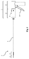
[0034]図1は、手術器具2の一実施形態を示す。手術器具は、ハンドル4と、ハンドル4から先端側に延出する長尺状シャフトアセンブリ6と、を含む。長尺状シャフトアセンブリ6の先端部から留置されるファスナに加え、長尺状シャフトアセンブリは関節動作可能部分8を含んでもよい。関節動作可能部分8の関節動作は、関節動作可能部分8を所望の関節角度へと変化するために1つ又は複数の位置間において動作してもよい関節動作制御部10によって制御してもよい。手術器具2は、また、ファスナを留置するためのファスナ留置システム210を作動させるためのトリガ12を含んでもよい(図12を参照)。
FIG. 1 shows one embodiment of a surgical instrument 2. The surgical instrument includes a handle 4 and an
[0035]図1に示される関節動作可能部分8は、関節動作制御部10を用いて、非関節(すなわち直線)動作位置などの第1の位置と、完全関節動作位置などの第2の位置との間において移動してもよい。実施形態によっては、関節動作可能部分8は1つ又は複数の予め選択した関節角度に変化してもよく、あるいは、関節動作可能部分8は1つ又は複数の任意の(すなわち予め選択されていない)関節角度に調整してもよい。関節動作可能部分8は少なくとも第1の方向において関節式に動作してもよい。関節動作可能部分が少なくとも第2の方向において関節動作する実施形態もまた想定される。例えば、関節動作可能部分8は約0°を超える関節角度に相当する第1の方向及び約0°未満の関節角度に相当する第2の方向に関節式に動作してもよい。あるいは又は上記に加えて、関節動作可能部分8はそれが少なくとも2つの方向において関節動作するように2つの異なる軸線の周りにおいて関節式に動作してもよい(例えば水平方向及び垂直方向における関節動作)。
[0035] The
[0036]いくつかの実施形態では、先端側先端の位置決めを容易にするために長尺状シャフトアセンブリ6を回転させることが望ましい場合がある。そのような実施形態の1つは図1及び図12に示される。長尺状シャフトアセンブリ6の回転は任意の適切な方法で提供してもよい。例えば、長尺状シャフトアセンブリ6は単にハンドル4の少なくとも一部に対し回転可能となるように構成してもよい。あるいは、長尺状シャフトアセンブリ6を含むハンドル4の一部はグリップを含む部分などのハンドル4の別の部分に対して回転可能であってもよい。そのような実施形態の1つを図1に示す。示される実施形態においては、手術器具2は、第1のハンドル部16と、長尺状シャフトアセンブリ6を含む第2のハンドル部18と、を含む。第1のハンドル部16及び第2のハンドル部18は互いに対して回転可能となるように任意の適切な方法で構成及び配置してもよい。図には回転可能な長尺状シャフトアセンブリ6又はハンドル4を含む手術器具を示すが、本開示はこの方法に限定されないため、一体型ハンドル及び/又はハンドルに対して固定された長尺状シャフトアセンブリ6を含む手術器具もまた可能であることは理解すべきである。
[0036] In some embodiments, it may be desirable to rotate the
[0037]特定の用途においては、関節動作可能部分8から先端側に配置された先端側剛性直線部12を含むと有利な場合がある。剛性直線部12は、長尺状シャフトアセンブリ6の先端部からのファスナの留置を補助するためのいくつかの特徴を含んでもよい。例えば、先端側剛性直線部12は、手術器具の作動前に最先端側ファスナをファスナ留置位置に保持するための、タブなどのファスナ保持要素を含んでもよい。更に、理論に拘束されることを望むものではないが、ファスナが長尺状シャフトアセンブリの関節動作可能部分周辺を通過する際、ファスナ留置システムのドライブシャフトがファスナに力を印加する場合、ドライブシャフトによってファスナの頭部に印加される力は対応するファスナの留置方向と完全に整列していない場合がある。したがって、ファスナを収容し、且つファスナ留置システムからの作動力をそのファスナに対しファスナ留置方向と同じ方向に印加することを可能にするほどの十分な長さを有する長尺状シャフトアセンブリの直線部分を設けるために先端側剛性直線部12を含むことが望ましい場合がある。理論によって拘束されることを望むものではないが、これにより、手術器具からファスナを留置するために必要な作動力が減少する結果となりうる。先端側剛性直線部12を含む手術器具2を本明細書中に記載し且つ図に示すが、手術器具が先端側剛性直線部を含まないように関節動作可能部分8が長尺状シャフトアセンブリ6の先端部まで延在する実施形態も想定されることは理解すべきである。
[0037] In certain applications, it may be advantageous to include a distal rigid
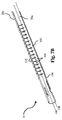
[0038]図2は、関節動作可能部分8を含む図1の長尺状シャフトアセンブリ6の先端部の拡大図を示す。示される実施形態においては、長尺状シャフトアセンブリ6は同軸状に整列した第1、第2及び第3の管状部材を含む。示される管状部材は、内部管状部材20aと、中間管状部材20bと、回転可能な外部管状部材20cと、を含む。図に示される実施形態においては、内部管状部材20a及び中間管状部材20bは関節動作可能部分8から先端側に配置された先端側位置136において互いに軸方向に固定される。しかしながら、特定の実施形態によっては、回転可能な外部管状部材20cは他の管状部材のいずれかに軸方向に固定されてもされなくてもよい。示される実施形態においては、手術器具の関節動作可能部分8を関節式に動作させるため内部管状部材20aは中間管状部材20bに対して付勢されてもよい。更に、以下に更に詳細に記載するように、関節動作可能部分8の関節動作を妨げるために外部管状部材20cは他の管状部材に対して回転してもよい。
[0038] FIG. 2 shows an enlarged view of the distal end of the
[0039]図3A〜5Aは、管状部材の可撓性部分をより良好に視覚化するために対となる図の間で90°回転させた種々の管状部材の側面図を示す。 [0039] FIGS. 3A-5A show side views of various tubular members rotated 90 ° between the paired views to better visualize the flexible portion of the tubular member.
[0040]図3A及び図3Bは、内部管状部材20aの可撓性部分の側面図及び下面図を示す。内部管状部材20aの可撓性部分は管状部材の一方の側に延在する1つの背骨100を含む。背骨100は管状部材の長さに沿って軸力を伝達可能な管状部材の連続部分に相当する。背骨100は内部管状部材20aに形成された一連のスロット102によって画定されてもよい。背骨100とスロット102は相互作用し、複数の一体成形ヒンジ106によって互いに接合された複数の可撓性セグメント104を形成してもよい。隣接する可撓性セグメント104は介在する一体成形ヒンジ106を中心として互いに対し枢動してもよい。内部管状部材20aに可撓性を付与するのはこの個々の可撓性セグメント104の相対枢動である。加えて、一体成形ヒンジ106の回転軸を中心とした優先曲げ方向124を画定するのは背骨100及びスロット102の向きである。理論によって拘束されることを望むものではないが、一体成形ヒンジ106は、一体成形ヒンジ106の回転軸を中心とした一体成形ヒンジ106の枢動に対応する方向以外の方向において曲げ抵抗の増加を示す。したがって、一体成形ヒンジ106が剛性の増加を示す方向は曲げ抵抗の方向に相当するものと解釈してもよい。示される実施形態においては、曲げ抵抗の方向126は、優先曲げ方向に対し垂直且つ内部管状部材20aの一体成形ヒンジ106の回転軸に平行な方向に相当してもよい。
[0040] FIGS. 3A and 3B show side and bottom views of the flexible portion of the inner
[0041]図4A及び図4Bは、中間管状部材20bの側面図及び下面図を示す。中間管状部材20b及び内部管状部材20aが組み立て済みの長尺状シャフトアセンブリ内に同軸状に配置された場合、中間管状部材20bは内部管状部材20aを収容するようなサイズ及び形状にしてもよい。上記と同様に、中間管状部材20bは、管状部材に形成された複数のスロット110によって画定される可撓性部分を含んでもよい。しかしながら、内部管状部材とは対照的に、中間管状部材20bの示される実施形態は、2つの背骨の両側に配置されたスロット110によって画定される2つの背骨108を含む。示される実施形態においては、背骨108は管状部材の可撓性部分に沿って先端側に延在し、且つ管状部材の両側に配置されているが、背骨の互いに対する他の配置構成もまた可能である。背骨108及びスロット110の示される配置構成により、背骨108の上下に配置された隣接する2つの別個の組の可撓性セグメント112が形成されることとなる。各可撓性セグメント112は背骨108とスロット110との接合部間に形成された一体成形ヒンジ114を中心に枢動可能である。いくつかの実施形態では、及び図に示すように、各スロット110は1つ又は複数の二次スロット111と対応付けられてもよい。示される二次スロット111はスロット110の端部に位置する水平に配置されたスロットである。理論によって拘束されることを望むものではないが、二次スロット111により、特定の関節動作力(articulation force)に対しより大きな可撓性を可撓性セグメント112に付与しうる一体成形ヒンジ114に相当する材料の量が低減されてもよい。二次スロットは背骨と可撓性セグメントとの間の接合部にある水平スロットとして示したが、他の配置構成もまた可能である。
[0041] FIGS. 4A and 4B show side and bottom views of the intermediate
[0042]理論によって拘束されることを望むものではないが、中間管状部材の両側に位置する2つの背骨108を含むことにより、優先曲げ方向及び曲げ抵抗の方向が内部管状部材20aに関して上記したものとは異なるものとなる。より具体的には、2つの背骨108を含むことにより、背骨108間に延在する面に平行する方向において背骨に対し垂直に配向された回転軸を有する一体成形ヒンジ114となる(すなわち、この回転軸は2つの対向する背骨間に延在する)。加えて、背骨の両側のスロットパターンの対称度により、背骨108の上下に配置された一体成形ヒンジ114は互いに整列した回転軸を有する。したがって、中間管状部材20bの個々の可撓性セグメント112及び全体的な可撓性部分は、背骨108間に延在する面に垂直な、一体成形ヒンジ114を中心とした回転の方向に相当する優先曲げ方向128を示す。
[0042] While not wishing to be bound by theory, including two
[0043]管状部材の両側の2つの背骨108に対応付けられた中間管状部材20bの個々の可撓性セグメント112により、中間管状部材20bは、また、内部管状部材20aに関して上記した方向とは異なる曲げ抵抗の増加方向を示す。理論によって拘束されることを望むものではないが、中間管状部材20bは2つの背骨間に延在する面に平行な方向において曲げ抵抗の増加を示す。認められる曲げ抵抗の増加は、2つの背骨間に延在する面に平行な方向に管状部材が曲がる最中に生じる可能性のある管状部材の伸展及び収縮に管状部材の両側の背骨が抵抗することに起因するものであってもよい。更に、各可撓性セグメント112は管状部材の両側の背骨108の両方に連結されている。したがって、背骨がそれらの長さに沿って延在する箇所において互いに対し事実上固定されているために2つの背骨108の互いに対する動きが一層限定されてもよく、これにより、管状部材の曲げに対する抵抗が更に増加してもよい。この挙動は、長尺状シャフトアセンブリの曲げを容易にするために管状部材の伸展及び収縮の両方に適応するように特に構成されている可撓性セグメント112及びスロット110とは対照的となりうる。上記に鑑み、中間管状部材20bに2つの背骨108を含むことにより、優先曲げ方向128及び一体成形ヒンジ114の回転方向に対し垂直な曲げ抵抗増加方向130が生成されることになる。更に、曲げ抵抗増加方向130は、また、2つの背骨108間に延在する面及び一体成形ヒンジ114の回転軸に平行であってもよい。
[0043] Due to the individual
[0044]図5A及び図5Bは、内部管状部材20a、中間管状部材20b及び外部管状部材20cが長尺状シャフトアセンブリ6内に同軸状に配置された場合、内部管状部材20a及び中間管状部材20bを収容するようなサイズ及び形状にしてもよい外部管状部材20cを示す。加えて、外部管状部材20cの示される実施形態は、中間管状部材20bに関して上記した背骨116、スロット118、可撓性セグメント120及び一体成形ヒンジ122と類似の配置構成を示してもよい。したがって、中間管状部材20bと同様に、外部管状部材20cは、一体成形ヒンジ122を中心とした回転方向に相当し、且つ背骨116間に延在する面に垂直な優先曲げ方向132を示してもよい。加えて、外部管状部材20cは優先曲げ方向132に対し垂直な曲げ抵抗増加方向134を示してもよい。曲げ抵抗増加方向134は、また、2つの背骨116間に延在する面及び一体成形ヒンジ122の回転軸に平行であってもよい。
[0044] FIGS. 5A and 5B show that the inner
[0045]図6A〜7Bは、長尺状シャフトアセンブリ6がどのように関節式に動作しうるかについての一実施形態を示す。長尺状シャフトアセンブリがどのように関節式に動作するかについての図示を明確にするため、図には内部管状部材20a及び中間管状20bのみを示す。
[0045] FIGS. 6A-7B illustrate one embodiment of how the
[0046]示される実施形態においては、内部管状部材20aは中間管状部材20b内に同軸状に配置してもよい。管状部材20a及び20bの可撓性部分は整列して関節動作可能部分8を形成してもよい。更に、管状部材20aと管状部材20bとは、関節動作可能部分8に対し先端側に配置されている先端側位置136において互いに軸方向に固定されてもよい。管状部材は溶接、ろう付け、はんだ付け、接着剤、機械的なインターロック機能又は管状部材を互いに固定可能な任意の他の適切な方法を用いて互いに固定してもよい。管状部材20aと管状部材20bは先端側位置136において互いに軸方向に固定してもよいが、管状部材20aと管状部材20bはそれらの基端部において互いに対し自由に動いてもよいことに留意すべきである。図に示されるように、管状部材20a及び20bは、また、ハンドル内の構成要素と相互作用して中間管状部材20bに対し内部管状部材20aを付勢するための保持要素126及び128を含んでもよい。
[0046] In the illustrated embodiment, the inner
[0047]図6Aは、いずれの管状部材も圧縮力下又は引張力下にない非付勢位置にある管状部材20a及び管状部材20bを示す。使用者が関節動作可能部分8を関節式に動作させようとする場合、内部管状部材20aは力Fによって中間管状部材20bに対し先端側に移動されてもよい(図6Bを参照)。特定の実施形態によっては、先端側方向に向けられた力は第1の方向の関節動作を生じてもよく、基端側方向に向けられた力は第1の方向とは逆の第2の方向の関節動作を生じてもよい。理論によって拘束されることを望むものではないが、内部管状部材20aが中間管状部材20bに対し移動すると内部管状部材20aにおいて圧縮力又は引張力が生成され、相対移動の方向に応じて対応する引張力又は圧縮力が中間管状部材20bにて生成される。管状部材の可撓性部分との圧縮力及び引張力の相互作用により図6Bに示される関節動作が生じる。
[0047] FIG. 6A shows
[0048]図7A〜7Bは、中間管状部材20bに対する内部管状部材20aの付勢により関節運動がどのように生成されるかについてより良く示すための、内部管状部材20a及び中間管状部材20bによって形成された関節動作可能部分8の外部斜視図及び断面図を示す。前述のように、内部管状部材20aと中間管状部材20bとは先端側位置136において互いに軸方向に固定されるが、先端側位置136の基端側の位置においては互いに対し自由に動く。理論によって拘束されることを望むものではないが、管状部材の1つに力が印加されると、1つの管状部材に圧縮力が印加され、他方の管状部材に引張力が印加される。各可撓性セグメント104及び112は他の隣接する可撓性セグメントに対して自由に動くことから、示される実施形態の管状部材の可撓性セグメント104及び112は管状部材に印加される圧縮荷重及び引張荷重を支持しないことに留意すべきである。その代わりに、背骨100及び108が管状部材20a及び20bに印加される圧縮荷重及び引張荷重を支持する。圧縮荷重及び引張荷重の支持に加え、上記の理由で付勢力が印加された場合、背骨100及び108、管状部材は同じ長さのままである。これに対し、管状部材の可撓性セグメント104及び112は付勢力が印加されると互いに対し伸展及び収縮してもよい。
[0048] FIGS. 7A-7B are formed by an inner
[0049]図7Bによって最も良く示されるように、及び理論に拘束されることを望むものではないが、内部管状部材20aに力が印加されると、背骨100は管状部材20aと管状部材20bとが互いに軸方向に固定された先端側位置136において長尺状シャフトアセンブリの一方の側に力を印加する。内部管状部材20aの背骨100から間隔を空けて配置された中間管状部材20bの背骨108によって、対応する力が長尺状シャフトアセンブリに印加される。背骨100及び背骨108によるこの離間した力の印加により、長尺状シャフトアセンブリ6において曲げモーメントが生じ、その結果、関節動作可能部分8の一方の側における管状部材の可撓性セグメント104及び112の圧縮が生じる。可撓性セグメント104及び112が枢動して印加された曲げモーメントに適応する一方で背骨100及び108は同じサイズのままであるため、関節動作可能部分8は関節式に動く。内部管状部材に反対方向の力が印加された場合、可撓性セグメント104及び112は関節動作可能部分8の一方の側において伸張し、長尺状シャフトアセンブリ6は反対方向に関節式に動くことに留意すべきである。
[0049] As best shown by FIG. 7B and not wishing to be bound by theory, when a force is applied to the inner
[0050]管状部材の背骨が印加される力をどのように支持して関節動作可能部分8を関節式に動作させるかを考察することに加え、管状部材の互いに対する中立曲げ軸を用いた関節動作可能部分8の関節動作についても記載しうる。理論によって拘束されることを望むものではないが、軸方向に向けられた力が物体に印加される場合、この力は中立曲げ軸に沿って印加される力に近似してもよい。関節動作可能部分8内において、内部管状部材20aの中立曲げ軸138は背骨100に相当する。これに対し、中間管状部材20bの両側に位置する、2つの先端側に延在する背骨108を含むことにより、中間管状部材20bは中間管状部材20bの中心軸に相当する中立曲げ軸140を有する。したがって、管状部材の1つに印加される付勢力により、等しく且つ反対の力が2つのオフセットした中立曲げ軸に沿って印加されてもよい。オフセットした中立曲げ軸に沿って管状部材に印加される力により、上記のように、ここでも、関節動作可能部分8を関節式に動作させるための曲げモーメントが長尺状シャフトアセンブリ6内に生じてもよい。
[0050] In addition to considering how the spine of the tubular member supports the applied force to articulate the
[0051]特定パターンのスロット及び背骨を有する管状部材を図に示し且つ本明細書中に記載したが、手術器具の所望の関節動作を提供するための異なるパターンのスロット及び背骨並びに異なる数の背骨を有する管状部材の他の配置構成もまた可能であることは理解すべきである。更に、本開示は任意の特定の形態の関節動作制御部又は任意の特定の形態の関節に限定されないため、他の種類の関節を手術器具に組み込んでもよい。 [0051] Although tubular members having particular patterns of slots and spines are shown in the figures and described herein, different patterns of slots and spines and different numbers of spines to provide the desired articulation of the surgical instrument It should be understood that other arrangements of the tubular member having the are also possible. Further, since the present disclosure is not limited to any particular form of joint motion control or any particular form of joint, other types of joints may be incorporated into the surgical instrument.
[0052]ここで、関節動作ロック機構がどのように動作しうるかについて述べると、図8〜11は、関節動作可能構成と非関節動作可能構成との間において回転してもよい回転可能な外部管状部材20cを備えた長尺状シャフトアセンブリ6を示す。
[0052] Referring now to how the articulation locking mechanism may operate, FIGS. 8-11 illustrate a rotatable external that may rotate between an articulatable configuration and a non-articulatable configuration. An
[0053]図8〜9は、関節動作可能構成にある長尺状シャフトアセンブリ6の概略分解図及び断面図を示す。示される実施形態においては、内部管状部材20aは、外部管状部材20c内に配置された中間管状部材20b内に配置されている。示される構成においては、各管状部材20a〜20cの優先曲げ方向124、128及び132は互いに整列している。同様に、内部管状部材20aの背骨100は中間管状部材20bの背骨108及び外部管状部材20cの背骨116に対し垂直である。示される実施形態においては、長尺状シャフトアセンブリ6の関節動作方向は内部管状部材20aの優先曲げ方向124に相当してもよい。したがって、外部管状部材20cの優先曲げ方向132は長尺状シャフトアセンブリ6の関節動作方向と整列している。各管状部材の優先曲げ方向が互いに整列しており、且つ長尺状シャフトアセンブリ6の関節動作方向と整列しているため、長尺状シャフトアセンブリ6は対応する関節動作制御部によって付勢されると関節式に動作してもよい。
[0053] FIGS. 8-9 show schematic exploded and cross-sectional views of the
[0054]長尺状シャフトアセンブリ6の関節動作を妨げようとする場合、外部管状部材20cは内部管状部材20a及び中間管状部材20bに対し図10〜11に示される非関節動作可能構成へと回転させてもよい。この回転は任意の適切な角度であってもよいが、示される実施形態においては、外部管状部材20cは関節動作可能構成と非関節動作可能構成との間において約90°回転する。図に示されるように、内部管状部材20a及び中間管状部材20bの優先曲げ方向124及び128は関節動作のため整列したままである。しかしながら、外部管状部材20cの優先曲げ方向132は優先曲げ方向124及び128ともはや整列していない。その代わりに、外部管状部材20cの曲げ抵抗の方向134は優先保留方向124及び128と整列している。更に、内部管状部材20aの背骨100は中間管状部材20bの背骨108に対し垂直であり、且つ外部管状部材20cの背骨116と整列している。上に示したように、長尺状シャフトアセンブリ6の関節動作方向は優先曲げ方向124、内部管状部材20aに相当してもよい。したがって、示される実施形態においては、曲げ抵抗の方向134は長尺状シャフトアセンブリ6の関節動作方向と整列している。示される構成においては、外部管状部材20cの曲げ抵抗の方向134が関節動作方向並びに他の管状部材20a及び20bの優先曲げ方向と整列していることにより、外部管状部材20cは長尺状シャフトアセンブリの関節動作を妨げてもよい。
[0054] When attempting to hinder the articulation of the
[0055]管状部材に関して、所望の優先曲げ方向及び曲げ抵抗の方向を提供するための背骨及びスロットの特定の配置構成について上で述べてきたが、本開示は示される管状部材のみに限定されないことは理解すべきである。例えば、特定パターンのスロット及び背骨を含む管状部材の使用に加え、本開示では、1つ又は複数の予め選択した方向に移動可能となるよう構成及び配置された個々の関節式リンクを含む可撓性部を含む管状部材を使用してもよい。したがって、本開示は、一般に、優先曲げ方向及び曲げ抵抗の方向をデバイスの関節動作可能部分と選択的に整列し、デバイスの関節動作を選択的に可能にする又は妨げるように動作することが可能な、任意の適切に適応させた構成要素を含む任意のデバイスの関節動作に適用されるものと解釈すべきである。 [0055] While specific arrangements of the spine and slot to provide the desired preferential bending direction and direction of bending resistance have been described above with respect to tubular members, the present disclosure is not limited to only the tubular members shown. Should be understood. For example, in addition to the use of a tubular member that includes a specific pattern of slots and spines, the present disclosure includes flexibility including individual articulated links that are configured and arranged to be movable in one or more preselected directions. A tubular member including a sex part may be used. Thus, the present disclosure can generally operate to selectively align the preferential bending direction and the direction of bending resistance with the articulatable portion of the device and selectively enable or prevent articulation of the device. It should be construed as applied to the articulation of any device including any appropriately adapted component.
[0056]上記実施形態では、手術器具の関節動作を選択的に妨げるために使用される管状部材を、長尺状シャフトアセンブリの外側にあるものとして示してきた。しかしながら、本開示は管状部材の特定位置について限定されない。例えば、長尺状シャフトアセンブリは、内側管状部材、中間管状部材又は外側管状部材として配置された関節動作を選択的に妨げるための管状部材を含んでもよい。 [0056] In the above embodiments, the tubular member used to selectively prevent articulation of the surgical instrument has been shown as being outside the elongate shaft assembly. However, the present disclosure is not limited with respect to a particular position of the tubular member. For example, the elongate shaft assembly may include a tubular member for selectively preventing articulation disposed as an inner tubular member, an intermediate tubular member, or an outer tubular member.
[0057]いくつかの実施形態では、上に開示した3つの管状部材の代わりに、2つの管状部材を用いて関節式に動作し且つ関節動作を選択的に妨げてもよい長尺状シャフトアセンブリを提供すると有利な場合がある。このような一実施形態においては、管状部材は長尺状シャフトアセンブリを関節式に動作させるための内部管状部材及び中間管状部材に関して上記したものと類似の機能を提供するように構成及び配置してもよい。加えて、上述の実施形態と同様に、管状部材は長尺状シャフトアセンブリの関節動作を容易にするために先端側位置に互いに軸方向に固定してもよい。しかしながら、長尺状シャフトアセンブリの関節動作を容易にするために互いに軸方向に固定されることに加え、管状部材は、また、長尺状シャフトアセンブリの関節動作を選択的に可能にする又は妨げるために互いに対して回転可能であってもよい。上記の実施形態と同様に、長尺状シャフトアセンブリは管状部材の優先曲げ方向が互いに整列した場合に関節動作可能であってもよい。更に、長尺状シャフトアセンブリは、1つの管状部材の曲げ抵抗の方向が他の管状部材の優先曲げ方向及び/又は長尺状シャフトアセンブリ6の関節動作方向と整列した場合に関節動作を妨げられてもよい。
[0057] In some embodiments, instead of the three tubular members disclosed above, two tubular members may be used to articulate and selectively prevent articulation It may be advantageous to provide In one such embodiment, the tubular member is configured and arranged to provide a function similar to that described above with respect to the inner and intermediate tubular members for articulating the elongate shaft assembly. Also good. In addition, similar to the embodiments described above, the tubular members may be axially secured to each other at the distal position to facilitate articulation of the elongate shaft assembly. However, in addition to being axially secured to one another to facilitate articulation of the elongate shaft assembly, the tubular member also selectively enables or prevents articulation of the elongate shaft assembly. Therefore, they may be rotatable with respect to each other. Similar to the above embodiment, the elongate shaft assembly may be articulatable when the preferential bending directions of the tubular members are aligned with each other. Further, the elongate shaft assembly is prevented from articulating when the direction of bending resistance of one tubular member is aligned with the preferential bending direction of the other tubular member and / or the articulating direction of the
[0058]上記実施形態の2つの管状部材は任意の適切な連結を用いて先端側位置において互いに軸方向に固定される一方で回転自在に結合されてもよい。例えば、一実施形態においては、管状部材は、回転を可能にしつつも管状部材を互いに対し軸方向に拘束するボス及び対応するシェルフを含んでもよい。別の実施形態においては、管状部材は、管状部材の互いに対する回転を可能にしつつも管状部材を軸方向に拘束するインターロック式機械的要素を含んでもよい。このような一実施形態の1つの例は、先端部にある、他の管状部材の対応する特徴によって捕捉されるリップを備えた管状部材を含んでもよい。他の構成も可能であり、本開示は上記の回転可能なカップリングのみに限定されないことは理解すべきである。加えて、いくつかの実施形態では、管状部材の互いに対する回転を補助するために回転可能なカップリング内に存在する摩擦を低減することが望ましい場合がある。したがって、潤滑、軸受、低摩擦材料及び他の適切な特徴などの別の管状部材に対する管状部材の回転を容易にするための特徴を含むと有利な場合がある。 [0058] The two tubular members of the above embodiments may be rotatably coupled while being axially fixed to each other in a distal position using any suitable connection. For example, in one embodiment, the tubular member may include a boss and corresponding shelf that axially restrains the tubular member relative to each other while allowing rotation. In another embodiment, the tubular member may include interlocking mechanical elements that axially constrain the tubular member while allowing the tubular members to rotate relative to each other. One example of such an embodiment may include a tubular member with a lip at the tip that is captured by corresponding features of other tubular members. It should be understood that other configurations are possible and that the present disclosure is not limited to only the rotatable coupling described above. In addition, in some embodiments, it may be desirable to reduce the friction present in the rotatable coupling to assist in rotating the tubular members relative to each other. Accordingly, it may be advantageous to include features to facilitate rotation of the tubular member relative to another tubular member, such as lubrication, bearings, low friction materials, and other suitable features.
[0059]いくつかの実施形態では、管状部材の1つ又は複数に異なる構成又はパターンのスロット及び背骨を設けることが望ましい場合がある。本開示は任意の特定の構造に限定されないため、管状部材の異なる配置構成のスロット及び背骨は、当業者には明らかなように、異なる関節動作特性、可動構成要素間の干渉の低減、選択した方向における曲げ抵抗の増加、選択した方向における曲げ抵抗の低下、関節動作範囲の増加、複雑な関節動作方向及び他の利点を含む利点を提供してもよい。異なる構成及びパターンのスロット及び背骨には、螺旋状に配置されたスロット、傾斜したスロット、管状部材の周方向に配置された複数の先端側に延在する背骨、管状部材の軸に対し特定の角度で配向された背骨、及び任意の他の適切なパターン又は配置構成を含んでもよい。加えて、管状部材はレーザー切断、研削、水切断、フライス削り又は任意の他の適切な方法を用いて形成してもよい。 [0059] In some embodiments, it may be desirable to provide different configurations or patterns of slots and spines in one or more of the tubular members. Since the present disclosure is not limited to any particular structure, slots and spines with different arrangements of tubular members have been selected with different articulation characteristics, reduced interference between movable components, as will be apparent to those skilled in the art. Benefits may be provided including increased bending resistance in the direction, reduced bending resistance in the selected direction, increased articulation range, complex articulation directions and other benefits. Slots and spines of different configurations and patterns include spirally arranged slots, inclined slots, a plurality of distally extending spines arranged in the circumferential direction of the tubular member, specific to the axis of the tubular member It may include an angularly oriented spine and any other suitable pattern or arrangement. In addition, the tubular member may be formed using laser cutting, grinding, water cutting, milling or any other suitable method.
[0060]理論によって拘束されることを望むものではないが、管状部材の大きな関節角度により、隣接する可撓性セグメント間の接触が生じてもよく、これにより、長尺状シャフトアセンブリの更なる関節動作を妨げてもよい。しかしながら、いくつかの実施形態では、特定用途のために大きな関節角度が望ましい場合がある。したがって、いくつかの実施形態においては、大きな関節角度には、可撓性セグメントあたりの同じ角移動を維持しつつもより大きな角度まで関節動作可能なより長い関節動作可能部分を設けることによって対応してもよい。あるいは、いくつかの実施形態では、大きな関節角度に対応するために可撓性セグメントあたりの最大角移動量(maximum angular displacement)を増加してもよい。可撓性セグメントあたりの最大角移動量は、隣接する可撓性セグメント間の接触が生じる角度を増加するためにスロットの幅を増加することによって、又は可撓性セグメントに起伏又は切り込みを含むことによって増加してもよい。上記実施形態の組み合わせを用いてもよい(例えば、より長い関節動作可能部分及び可撓性セグメントに形成された起伏)。上記実施形態は許容関節角度の増加に関するが、いくつかの実施形態では、長尺状シャフトアセンブリの関節角度を限定することが望ましい場合がある。このような一実施形態においては、関節動作可能部分の長さ及び/又は可撓性セグメントあたりの最大角移動量は所望の最大関節角度を提供するように選択してもよい。 [0060] While not wishing to be bound by theory, large joint angles of the tubular member may cause contact between adjacent flexible segments, thereby further increasing the length of the elongate shaft assembly. Joint movement may be hindered. However, in some embodiments, a large joint angle may be desirable for specific applications. Thus, in some embodiments, large joint angles are accommodated by providing longer articulable portions that can articulate to larger angles while maintaining the same angular movement per flexible segment. May be. Alternatively, in some embodiments, the maximum angular displacement per flexible segment may be increased to accommodate large joint angles. Maximum angular travel per flexible segment includes increasing the width of the slot to increase the angle at which contact between adjacent flexible segments occurs, or including undulations or notches in the flexible segment It may be increased by. Combinations of the above embodiments may also be used (eg, undulations formed on longer articulatable parts and flexible segments). While the above embodiments relate to increasing the allowable joint angle, in some embodiments it may be desirable to limit the joint angle of the elongate shaft assembly. In one such embodiment, the length of the articulatable portion and / or the maximum amount of angular movement per flexible segment may be selected to provide the desired maximum joint angle.
[0061]いくつかの実施形態では、及び上に示したように、手術器具を2つ以上の方向に関節式に動作させることが望ましい場合がある。例えば、手術器具を垂直方向、水平方向又は垂直方向と水平方向との間の方向に関節式に動作させることが望ましい場合がある。これらの複雑な関節動作は任意の数の方法において提供してもよい。例えば、一実施形態においては、複数の方向における関節動作を提供するため、適切に配向された背骨及びスロットを含む3つ以上の管状部材を用いてもよい。あるいは、可撓性管状部材は、管状部材を複数の方向において関節動作可能なワイヤ又はスラットなどの適切な関節機構を含んでもよい。手術器具を複数の方向において関節動作させることに加え、また、関節動作可能方向のうちの1つ又は全てにおける手術器具の関節動作を選択的に可能にする又は妨げることが望ましい場合がある。このような一実施形態においては、関節動作方向のうちのいずれか1つ又は全てにおける手術器具の関節動作を可能にする又は妨げるために1つ又は複数の管状部材を用いてもよい。例えば、1つの管状部材が、関節動作可能方向のうちの1つ又は全てにおける手術器具の関節動作を選択的に可能にする又は妨げるために複数の関節動作方向と選択的に整列してもよい複数の優先曲げ方向及び複数の曲げ抵抗の方向を含んでもよい。あるいは、それぞれが優先曲げ方向及び曲げ抵抗の方向を含む複数の管状部材を用いてもよい。このような一実施形態においては、複数の管状部材のそれぞれは特定の方向における手術器具の関節動作を選択的に可能にする又は妨げるように配向してもよい。複数の管状部材を用いた他の構成もまた可能である。 [0061] In some embodiments, and as indicated above, it may be desirable to articulate the surgical instrument in more than one direction. For example, it may be desirable to articulate the surgical instrument in a vertical direction, a horizontal direction, or a direction between the vertical and horizontal directions. These complex articulations may be provided in any number of ways. For example, in one embodiment, more than two tubular members including appropriately oriented spines and slots may be used to provide articulation in multiple directions. Alternatively, the flexible tubular member may include a suitable articulation mechanism such as a wire or slat capable of articulating the tubular member in multiple directions. In addition to articulating the surgical instrument in multiple directions, it may also be desirable to selectively enable or prevent articulation of the surgical instrument in one or all of the articulatable directions. In one such embodiment, one or more tubular members may be used to enable or prevent articulation of the surgical instrument in any one or all of the articulation directions. For example, a tubular member may be selectively aligned with a plurality of articulation directions to selectively enable or prevent articulation of a surgical instrument in one or all of the articulatable directions. A plurality of preferential bending directions and a plurality of bending resistance directions may be included. Alternatively, a plurality of tubular members each including a preferential bending direction and a bending resistance direction may be used. In one such embodiment, each of the plurality of tubular members may be oriented to selectively enable or prevent articulation of the surgical instrument in a particular direction. Other configurations using multiple tubular members are also possible.
[0062]図12は、手術器具2に組み込まれた、上記したような内部管状部材と、中間管状部材と、外部管状部材と、を含む、長尺状シャフトアセンブリ6を示す。示される実施形態においては、長尺状シャフトアセンブリ6はハンドル4から先端側に延出し、且つ関節動作制御部10と対応付けられている。より具体的には、関節動作制御部10はスロット202を含む回転可能な構成要素である。スロット202は関節カップリング200と対応付けられた対応するピン204と相互作用するようなサイズ及び形状である。関節カップリング200は、上に示したように内部管状部材及び中間管状部材の1つを選択的に移動することによって図1に示される関節動作可能部分8の関節動作を制御するために長尺状シャフトアセンブリ6に結合されている。より具体的には、関節動作制御部10が回転すると、ピン204、関節カップリング200及び対応する管状部材は基端側方向又は先端側方向のいずれかに選択的に移動し、関節動作可能部分8を関節式に動作させる又は真直にする。
FIG. 12 shows an
[0063]場合によっては、及び図に示すように、スロット202はピン204のための2つの載置位置を提供するような形状にしてもよい。これら位置は関節動作可能部分8の非関節動作位置及び完全関節動作位置に相当してもよい。他の実施形態においては、スロット202は関節動作可能部分8の複数の関節動作位置を提供するために2つを超える載置位置を含むような形状にされ且つそのように配置されてもよい。あるいは、スロット202は非関節動作位置と完全関節動作位置との間において漸進的な移行を提供してもよい。このような一実施形態においては、関節動作制御部10はロック機構を含んでもよく、あるいはピン204及び同様に関節動作可能部分8を非関節動作位置と完全関節動作位置との間の任意の所望の関節角度にて維持するほど十分な摩擦を有してもよい。加えて、上に示したように、場合によっては、2つの方向(すなわち上下)に関節動作を提供することが望ましい場合がある。このような一実施形態においては、スロット202は、関節動作可能部分8の両方向における関節動作を可能にするために、非関節動作位置に相当する第1の載置位置及びその第1の載置位置のいずれかの側にある1つ又は複数の載置位置を含むような形状にされ且つそのように配置されてもよい。
[0063] In some cases and as shown, the
[0064]特定の関節動作制御部及び関節カップリングを図に示し且つ本明細書中に記載したが、本開示は示される実施形態のみに限定されない。したがって、任意の適切な関節カップリング及び関節動作制御部が使用されうることは理解すべきである。更に、関節カップリング及び/又は関節動作可能部分8に関節動作制御部の動きを伝達するための任意の適切な方法もまた使用されうる。関節動作制御部は、また、基端側方向及び先端側方向における直線運動、垂直方向における直線運動、水平方向における直線運動、基端側方向又は先端側方向における回転、垂直方向における回転及び/又は水平方向における回転を含む任意の適切な動きを用いて種々の関節動作位置間において移動してもよい。関節動作制御部を2つ以上の位置間において移動するための上記の運動及び他の種類の運動の組み合わせもまた可能である。
[0064] Although specific joint motion controls and joint couplings are shown in the figures and described herein, the present disclosure is not limited to only the illustrated embodiments. Thus, it should be understood that any suitable joint coupling and joint motion controller may be used. Furthermore, any suitable method for transmitting the motion of the articulation control to the articulation coupling and / or
[0065]手術器具の関節動作を選択的に可能にする又は妨げるために外部管状部材20cの回転を制御するため、ハンドル4は外部管状部材20cに対応付けられた回転可能なカラー205を含んでもよい。示される実施形態においては、回転可能なカラー205の回転により、長尺状シャフトアセンブリの関節動作可能部分8に対し外部管状部材20cが直接回転し、外部管状部材20cの優先曲げ方向を、長尺状シャフトアセンブリ6の関節動作方向と整列した状態及び整列しない状態へと選択的に移動させる。したがって、回転可能なカラー205及び対応する外部管状部材20cの回転により、長尺状シャフトアセンブリ6の関節動作を選択的に可能にしても妨げてもよい。いくつかの実施形態では、回転可能なカラー205は関節動作可能位置と非関節動作可能位置との間においてのみ回転可能であってもよい。あるいは、回転可能なカラー205は、長尺状シャフトアセンブリの関節動作可能部分の部分的ロックを提供するために関節動作可能位置と非関節動作可能位置との間の任意の数の異なる位置に配置してもよい。回転可能なカラー205の位置決めを容易にするため、回転可能なカラー205は任意の数の予め選択した位置における外部管状部材20cの位置決め及び保持を容易にするための移動止め機構又は任意の他の適切な特徴を含んでもよい。しかしながら、移動止め機構又は外部管状部材20cの位置を制御するための他の適切な特徴を含まない実施形態もまた想定される。更に、外部管状部材20cの位置決めを制御するための特定の回転可能なカラーを示したが、外部管状部材20cを所望の向きに位置決め可能な任意の適切な構造を用いてもよい。例えば、外部管状部材20cを関節動作可能位置と非関節動作可能位置との間において移動するために、示される回転可能なカラーなどの直接カップリング及び変速機を含む間接カップリングの両方を用いてもよい。
[0065] The handle 4 may include a
[0066]前述のように、手術器具2は、また、図12に示されるようなファスナ留置システムを含んでもよい。ファスナ留置システム102はいくつかの異なる方法で具現化されてもよい。しかしながら、図12に示される特定の実施形態においては、ファスナ留置システムは、トリガ14と、剛性リンク206と、シャトル208と、パワーアシストデバイス210と、ドライブシャフト212と、図示しない他の構成要素と、を含んでもよい。手術器具2が作動されると、トリガ14の作動により、剛性リンク206が先端側に移動し、シャトル208が先端側に移動して、パワーアシストデバイス210にエネルギーを蓄積してもよい。予め選択した量の動作後、パワーアシストデバイス210は蓄積されたエネルギーを放出し、ドライブシャフト212を先端側へと加速させ、長尺状シャフトアセンブリ6の先端部からファスナを留置してもよい。
[0066] As described above, the surgical instrument 2 may also include a fastener placement system as shown in FIG. The
[0067]パワーアシストデバイス210は手術器具の長尺状シャフトアセンブリからのファスナの留置を補助することが可能な任意の適切な構造に相当してもよい。更に、特定の実施形態によっては、パワーアシストデバイス210は、ファスナを留置するのに必要な動力の全てを供給しても、ファスナを留置するのに必要な動力の一部のみを供給してもよい。1つの特定の実施形態においては、パワーアシストデバイス106は本出願と同日に出願された手術器具用のパワーアシストデバイス(POWER ASSIST DEVICE FOR A SURGICAL INSTRUMENT)という名称の米国特許出願第13/804,043号に開示されているパワーアシストデバイスに相当する。パワーアシストデバイスを含む手術器具が示されているが、いくつかの実施形態では、手術器具2はパワーアシストデバイスを含まなくてもよく、この場合、トリガ14の作動によりドライブシャフト212を直接的又は間接的に移動し、長尺状シャフトアセンブリ6の先端部からファスナを留置してもよい。
[0067] The
[0068]本教示を種々の実施形態及び例とともに記載してきたが、本教示はそのような実施形態又は例に限定されることを意図しない。逆に、当業者には理解されるように、本教示は種々の代替物、変更形態及び均等物を含む。したがって、前述の記載及び図面は単に例である。 [0068] While the present teachings have been described in conjunction with various embodiments and examples, the present teachings are not intended to be limited to such embodiments or examples. On the contrary, the present teachings include various alternatives, modifications and equivalents, as will be appreciated by those skilled in the art. Accordingly, the foregoing description and drawings are merely examples.
Claims (16)
前記ハンドルから先端側に延出する長尺状シャフトアセンブリであって、
第1の優先曲げ方向を有する第1の可撓性部分を含む第1の管状部材と、
第2の優先曲げ方向を有する第2の可撓性部分を含む第2の管状部材と、
第3の優先曲げ方向及び曲げ抵抗の方向を有する第3の可撓性部分を含む第3の管状部材と、を含む長尺状シャフトアセンブリと、を含み、
前記第1の管状部材、前記第2の管状部材及び前記第3の管状部材が同軸上に配置され、前記第1の管状部材及び前記第2の管状部材が前記第1の可撓性部分及び前記第2の可撓性部分から先端側の位置において互いに対し軸方向に固定されており、前記第3の管状部材が前記第1の管状部材及び前記第2の管状部材に対して回転可能であり、
前記第3の管状部材の回転により前記曲げ抵抗の方向が前記第1の優先曲げ方向及び前記第2の優先曲げ方向のうちの少なくとも1つと整列すると、前記第3の管状部材が前記第1の管状部材及び前記第2の管状部材の関節動作を妨げる、手術器具。 A handle,
An elongate shaft assembly extending from the handle toward the distal end;
A first tubular member including a first flexible portion having a first preferential bending direction;
A second tubular member including a second flexible portion having a second preferential bending direction;
An elongate shaft assembly comprising: a third tubular member including a third flexible portion having a third preferential bending direction and a bending resistance direction;
The first tubular member, the second tubular member, and the third tubular member are coaxially disposed, and the first tubular member and the second tubular member are the first flexible portion and The third tubular member is axially fixed with respect to each other at a position on the distal end side from the second flexible portion, and the third tubular member is rotatable with respect to the first tubular member and the second tubular member. Yes,
When the direction of the bending resistance is aligned with at least one of the first preferential bending direction and the second preferential bending direction by rotation of the third tubular member, the third tubular member is the first tubular member. A surgical instrument that prevents articulation of the tubular member and the second tubular member.
前記ハンドルから先端側に延出する長尺状シャフトアセンブリであって、
第1の背骨を備えた第1の可撓性部分を含む第1の管状部材と、
第2の背骨を備えた第2の可撓性部分を含む第2の管状部材とであって、前記第1の管状部材及び前記第2の管状部材が前記第1の可撓性部分及び前記第2の可撓性部分から先端側の位置において互いに対し軸方向に固定されている、第1の管状部材及び第2の管状部材と、
第3の背骨及び第4の背骨を備えた第3の可撓性部分を含む第3の管状部材と、を含み、
前記第1の管状部材、前記第2の管状部材及び前記第3の管状部材が同軸上に配置され、前記第3の管状部材が前記第1の管状部材及び前記第2の管状部材に対して回転可能である、長尺状シャフトアセンブリと、を含み、
前記第3の管状部材の回転により前記第3の背骨及び前記第4の背骨が前記第1の背骨と整列すると、前記第3の管状部材が前記第1の管状部材及び前記第2の管状部材の関節動作を妨げる、手術器具。 A handle,
An elongate shaft assembly extending from the handle toward the distal end;
A first tubular member including a first flexible portion with a first spine;
A second tubular member including a second flexible portion with a second spine, wherein the first tubular member and the second tubular member are the first flexible portion and the A first tubular member and a second tubular member fixed axially relative to each other at a position distal to the second flexible portion;
A third tubular member including a third flexible portion with a third spine and a fourth spine;
The first tubular member, the second tubular member, and the third tubular member are arranged coaxially, and the third tubular member is relative to the first tubular member and the second tubular member. An elongate shaft assembly that is rotatable, and
When the third spine and the fourth spine are aligned with the first spine by rotation of the third tubular member, the third tubular member becomes the first tubular member and the second tubular member. Surgical instruments that interfere with joint movement.
前記ハンドルから先端側に延出する長尺状シャフトアセンブリであって、
第1の背骨を備えた第1の可撓性部分を含む第1の管状部材と、
第2の背骨及び第3の背骨を備えた第2の可撓性部分を含む第2の管状部材と、を含み、
前記第1の管状部材及び前記第2の管状部材が同軸上に配置され、前記第1の管状部材及び前記第2の管状部材が前記第1の可撓性部分及び前記第2の可撓性部分から先端側の位置において互いに対し軸方向に固定されており、前記第2の管状部材が前記第1の管状部材に対して回転可能である、長尺状シャフトアセンブリと、を含み、
前記第2の管状部材の回転により前記第2の背骨及び第3の背骨が前記第1の背骨と整列すると、前記第2の管状部材が前記長尺状シャフトアセンブリの関節動作を妨げる、手術器具。 A handle,
An elongate shaft assembly extending from the handle toward the distal end;
A first tubular member including a first flexible portion with a first spine;
A second tubular member including a second flexible portion with a second spine and a third spine;
The first tubular member and the second tubular member are arranged coaxially, and the first tubular member and the second tubular member are the first flexible portion and the second flexible member. An elongate shaft assembly fixed axially relative to each other at a position distal from the portion, wherein the second tubular member is rotatable relative to the first tubular member;
A surgical instrument wherein the second tubular member prevents articulation of the elongate shaft assembly when rotation of the second tubular member aligns the second and third spines with the first spine. .
Applications Claiming Priority (3)
| Application Number | Priority Date | Filing Date | Title |
|---|---|---|---|
| US13/827,254 US9339271B2 (en) | 2013-03-14 | 2013-03-14 | Articulating surgical instruments |
| US13/827,254 | 2013-03-14 | ||
| PCT/US2014/017680 WO2014158523A1 (en) | 2013-03-14 | 2014-02-21 | Articulating surgical instruments |
Related Child Applications (1)
| Application Number | Title | Priority Date | Filing Date |
|---|---|---|---|
| JP2017143602A Division JP6469774B2 (en) | 2013-03-14 | 2017-07-25 | Articulated surgical instrument |
Publications (2)
| Publication Number | Publication Date |
|---|---|
| JP2016510651A JP2016510651A (en) | 2016-04-11 |
| JP6273345B2 true JP6273345B2 (en) | 2018-01-31 |
Family
ID=50240037
Family Applications (3)
| Application Number | Title | Priority Date | Filing Date |
|---|---|---|---|
| JP2016500334A Active JP6273345B2 (en) | 2013-03-14 | 2014-02-21 | Articulated surgical instrument |
| JP2017143602A Active JP6469774B2 (en) | 2013-03-14 | 2017-07-25 | Articulated surgical instrument |
| JP2018211089A Expired - Fee Related JP6719530B2 (en) | 2013-03-14 | 2018-11-09 | Articulated surgical instrument |
Family Applications After (2)
| Application Number | Title | Priority Date | Filing Date |
|---|---|---|---|
| JP2017143602A Active JP6469774B2 (en) | 2013-03-14 | 2017-07-25 | Articulated surgical instrument |
| JP2018211089A Expired - Fee Related JP6719530B2 (en) | 2013-03-14 | 2018-11-09 | Articulated surgical instrument |
Country Status (6)
| Country | Link |
|---|---|
| US (4) | US9339271B2 (en) |
| EP (3) | EP3375389B1 (en) |
| JP (3) | JP6273345B2 (en) |
| CA (2) | CA2903333C (en) |
| ES (2) | ES2676409T3 (en) |
| WO (1) | WO2014158523A1 (en) |
Cited By (2)
| Publication number | Priority date | Publication date | Assignee | Title |
|---|---|---|---|---|
| JP2017192802A (en) * | 2013-03-14 | 2017-10-26 | シー・アール・バード・インコーポレーテッドC R Bard Incorporated | Articulating surgical instruments |
| KR20180105969A (en) | 2017-03-16 | 2018-10-01 | 에스케이이노베이션 주식회사 | A bulky and precise machine and a method for transferring a slurry for secondary battery |
Families Citing this family (33)
| Publication number | Priority date | Publication date | Assignee | Title |
|---|---|---|---|---|
| WO2014052489A2 (en) * | 2012-09-26 | 2014-04-03 | Boston Scientific Scimed, Inc. | Catheter having rib and spine structure supporting multiple electrodes for renal nerve ablation |
| US9649109B2 (en) | 2013-03-14 | 2017-05-16 | C.R. Bard, Inc. | Surgical instrument with an actuation lockout |
| CN105992605B (en) * | 2013-12-19 | 2019-11-05 | 本迪特技术有限公司 | Manipulation instrument |
| US11103127B2 (en) * | 2014-10-20 | 2021-08-31 | Research Development International Corporation | Steerable micro-endoscope |
| US9700445B2 (en) * | 2014-11-04 | 2017-07-11 | Abbott Cardiovascular Systems, Inc. | One-way actuator knob |
| EP3261702A2 (en) | 2015-02-26 | 2018-01-03 | Stryker Corporation | Surgical instrument with articulation region |
| US20160302819A1 (en) * | 2015-04-16 | 2016-10-20 | Ethicon Endo-Surgery, Llc | Ultrasonic surgical instrument with articulating end effector having a curved blade |
| CN204654864U (en) * | 2015-04-29 | 2015-09-23 | 上海安清医疗器械有限公司 | Rigid pipe endoscope |
| US10376673B2 (en) | 2015-06-19 | 2019-08-13 | Evalve, Inc. | Catheter guiding system and methods |
| US10405876B2 (en) * | 2016-04-05 | 2019-09-10 | Ethicon Llc | Articulation joint for surgical instrument |
| NL2016900B1 (en) * | 2016-06-06 | 2017-12-13 | Fortimedix Surgical B V | Steerable instrument comprising a cylindrical diameter adaptation section |
| US9918705B2 (en) | 2016-07-07 | 2018-03-20 | Brian Giles | Medical devices with distal control |
| US10391274B2 (en) * | 2016-07-07 | 2019-08-27 | Brian Giles | Medical device with distal torque control |
| US11660106B2 (en) * | 2016-07-19 | 2023-05-30 | Cilag Gmbh International | Articulation joint having an inner guide |
| US10646689B2 (en) | 2016-07-29 | 2020-05-12 | Cephea Valve Technologies, Inc. | Mechanical interlock for catheters |
| US11324495B2 (en) | 2016-07-29 | 2022-05-10 | Cephea Valve Technologies, Inc. | Systems and methods for delivering an intravascular device to the mitral annulus |
| US10661052B2 (en) | 2016-07-29 | 2020-05-26 | Cephea Valve Technologies, Inc. | Intravascular device delivery sheath |
| US10974027B2 (en) | 2016-07-29 | 2021-04-13 | Cephea Valve Technologies, Inc. | Combination steerable catheter and systems |
| US10639151B2 (en) | 2016-07-29 | 2020-05-05 | Cephea Valve Technologies, Inc. | Threaded coil |
| US11109967B2 (en) | 2016-08-29 | 2021-09-07 | Cephea Valve Technologies, Inc. | Systems and methods for loading and deploying an intravascular device |
| US11045315B2 (en) | 2016-08-29 | 2021-06-29 | Cephea Valve Technologies, Inc. | Methods of steering and delivery of intravascular devices |
| US10933216B2 (en) | 2016-08-29 | 2021-03-02 | Cephea Valve Technologies, Inc. | Multilumen catheter |
| US10874512B2 (en) | 2016-10-05 | 2020-12-29 | Cephea Valve Technologies, Inc. | System and methods for delivering and deploying an artificial heart valve within the mitral annulus |
| HRP20230241T1 (en) * | 2016-12-16 | 2023-04-14 | Edwards Lifesciences Corporation | Deployment systems and tools for delivering an anchoring device for a prosthetic valve |
| CN110114012B (en) * | 2016-12-21 | 2022-06-24 | 爱惜康有限责任公司 | Surgical system including firing member rotatable into an articulated state to articulate an end effector of the surgical system |
| EP3692926A4 (en) | 2017-10-02 | 2021-07-14 | Lily Medtech Inc. | Medical imaging apparatus |
| US11103234B2 (en) * | 2018-01-10 | 2021-08-31 | C.R. Bard, Inc. | Articulating surgical instruments |
| US11134928B2 (en) * | 2018-01-10 | 2021-10-05 | C.R. Bard, Inc. | Articulating surgical instruments |
| US10779813B2 (en) * | 2018-01-10 | 2020-09-22 | C.R. Bard, Inc. | Articulating surgical instruments |
| WO2020068601A1 (en) * | 2018-09-24 | 2020-04-02 | Cottone Robert J | Systems and methods for tissue displacement |
| US11724068B2 (en) | 2018-11-16 | 2023-08-15 | Cephea Valve Technologies, Inc. | Intravascular delivery system |
| CN113546277B (en) * | 2021-07-23 | 2022-07-01 | 云南省阜外心血管病医院 | Medical catheter structure with rigidity capable of being adjusted rapidly |
| GB2610645B (en) * | 2021-09-14 | 2023-11-29 | I Q Endoscopes Ltd | Endoscopy system & elements thereof |
Family Cites Families (65)
| Publication number | Priority date | Publication date | Assignee | Title |
|---|---|---|---|---|
| US3802440A (en) | 1972-12-19 | 1974-04-09 | M Salem | Intubation guide |
| JP2938486B2 (en) * | 1989-12-28 | 1999-08-23 | 株式会社町田製作所 | Curved tube and manufacturing method thereof |
| WO1993013704A1 (en) | 1992-01-09 | 1993-07-22 | Endomedix Corporation | Bi-directional miniscope |
| US5417203A (en) | 1992-04-23 | 1995-05-23 | United States Surgical Corporation | Articulating endoscopic surgical apparatus |
| US5325845A (en) | 1992-06-08 | 1994-07-05 | Adair Edwin Lloyd | Steerable sheath for use with selected removable optical catheter |
| US5669926A (en) | 1993-01-25 | 1997-09-23 | Aust & Taylor Medical Corporation | Surgical instrument |
| US5643294A (en) | 1993-03-01 | 1997-07-01 | United States Surgical Corporation | Surgical apparatus having an increased range of operability |
| US5715817A (en) * | 1993-06-29 | 1998-02-10 | C.R. Bard, Inc. | Bidirectional steering catheter |
| US5501654A (en) | 1993-07-15 | 1996-03-26 | Ethicon, Inc. | Endoscopic instrument having articulating element |
| US5766196A (en) | 1994-06-06 | 1998-06-16 | Tnco, Inc. | Surgical instrument with steerable distal end |
| US5609601A (en) | 1994-09-23 | 1997-03-11 | United States Surgical Corporation | Endoscopic surgical apparatus with rotation lock |
| US5704534A (en) * | 1994-12-19 | 1998-01-06 | Ethicon Endo-Surgery, Inc. | Articulation assembly for surgical instruments |
| US20030069522A1 (en) * | 1995-12-07 | 2003-04-10 | Jacobsen Stephen J. | Slotted medical device |
| US5823066A (en) * | 1996-05-13 | 1998-10-20 | Ethicon Endo-Surgery, Inc. | Articulation transmission mechanism for surgical instruments |
| US5851212A (en) * | 1997-06-11 | 1998-12-22 | Endius Incorporated | Surgical instrument |
| US5921956A (en) | 1997-09-24 | 1999-07-13 | Smith & Nephew, Inc. | Surgical instrument |
| US6171316B1 (en) * | 1997-10-10 | 2001-01-09 | Origin Medsystems, Inc. | Endoscopic surgical instrument for rotational manipulation |
| US6746422B1 (en) | 2000-08-23 | 2004-06-08 | Norborn Medical, Inc. | Steerable support system with external ribs/slots that taper |
| US6048339A (en) | 1998-06-29 | 2000-04-11 | Endius Incorporated | Flexible surgical instruments with suction |
| US20040044350A1 (en) * | 1999-04-09 | 2004-03-04 | Evalve, Inc. | Steerable access sheath and methods of use |
| US6146338A (en) | 1999-04-23 | 2000-11-14 | Medtronic, Inc. | Apparatus for deflecting a catheter or lead |
| US6749560B1 (en) * | 1999-10-26 | 2004-06-15 | Circon Corporation | Endoscope shaft with slotted tube |
| AU2002224519A1 (en) * | 2000-07-21 | 2002-02-05 | Atropos Limited | A surgical instrument |
| US6656195B2 (en) | 2000-09-22 | 2003-12-02 | Medtronic Xomed, Inc. | Flexible inner tubular members and rotary tissue cutting instruments having flexible inner tubular members |
| US6419641B1 (en) * | 2000-11-28 | 2002-07-16 | Promex, Llc | Flexible tip medical instrument |
| US7101371B2 (en) * | 2001-04-06 | 2006-09-05 | Dycus Sean T | Vessel sealer and divider |
| ATE347393T1 (en) * | 2001-07-05 | 2006-12-15 | Precision Vascular Systems Inc | MEDICAL DEVICE HAVING A TORQUE-TRANSMITTING SOFT END PIECE AND METHOD FOR SHAPING IT |
| US20040199052A1 (en) | 2003-04-01 | 2004-10-07 | Scimed Life Systems, Inc. | Endoscopic imaging system |
| US7008375B2 (en) | 2003-04-03 | 2006-03-07 | Surgical Solutions Llc | Articulating shaft |
| US7842028B2 (en) * | 2005-04-14 | 2010-11-30 | Cambridge Endoscopic Devices, Inc. | Surgical instrument guide device |
| US7637903B2 (en) | 2004-02-09 | 2009-12-29 | Cryocor, Inc. | Catheter articulation segment with alternating cuts |
| US7678117B2 (en) * | 2004-06-07 | 2010-03-16 | Novare Surgical Systems, Inc. | Articulating mechanism with flex-hinged links |
| EP2656777A3 (en) * | 2004-08-31 | 2015-12-02 | Surgical Solutions LLC | Medical device with articulating shaft |
| US7785252B2 (en) * | 2004-11-23 | 2010-08-31 | Novare Surgical Systems, Inc. | Articulating sheath for flexible instruments |
| EP1709987B1 (en) | 2005-04-07 | 2009-12-23 | Creganna Technologies Limited | Steerable catheter assembly |
| WO2006119495A2 (en) | 2005-05-03 | 2006-11-09 | Hansen Medical, Inc. | Robotic catheter system |
| US8097003B2 (en) * | 2005-05-13 | 2012-01-17 | Boston Scientific Scimed, Inc. | Endoscopic apparatus with integrated variceal ligation device |
| US8052597B2 (en) * | 2005-08-30 | 2011-11-08 | Boston Scientific Scimed, Inc. | Method for forming an endoscope articulation joint |
| US7850623B2 (en) * | 2005-10-27 | 2010-12-14 | Boston Scientific Scimed, Inc. | Elongate medical device with continuous reinforcement member |
| US20070225562A1 (en) * | 2006-03-23 | 2007-09-27 | Ethicon Endo-Surgery, Inc. | Articulating endoscopic accessory channel |
| AU2007254126A1 (en) | 2006-05-19 | 2007-11-29 | Conmed Endoscopic Technologies, Inc. | Steerable medical instrument |
| US7955315B2 (en) * | 2006-07-24 | 2011-06-07 | Ethicon, Inc. | Articulating laparoscopic device and method for delivery of medical fluid |
| AU2007231733B2 (en) | 2006-11-28 | 2014-03-13 | Cathrx Ltd | A catheter steering system |
| US7771416B2 (en) * | 2007-06-14 | 2010-08-10 | Ethicon Endo-Surgery, Inc. | Control mechanism for flexible endoscopic device and method of use |
| CA2640345C (en) | 2007-10-05 | 2017-11-07 | Tyco Healthcare Group Lp | Surgical stapler having an articulation mechanism |
| ES2541117T3 (en) | 2008-03-10 | 2015-07-16 | Fortimedix Surgical B.V. | Instrument for endoscopic applications |
| US20110040308A1 (en) * | 2008-06-13 | 2011-02-17 | Ramiro Cabrera | Endoscopic Stitching Devices |
| US8262563B2 (en) | 2008-07-14 | 2012-09-11 | Ethicon Endo-Surgery, Inc. | Endoscopic translumenal articulatable steerable overtube |
| US8157834B2 (en) * | 2008-11-25 | 2012-04-17 | Ethicon Endo-Surgery, Inc. | Rotational coupling device for surgical instrument with flexible actuators |
| US20100191050A1 (en) | 2009-01-23 | 2010-07-29 | Ethicon Endo-Surgery, Inc. | Variable length accessory for guiding a flexible endoscopic tool |
| US7918376B1 (en) | 2009-03-09 | 2011-04-05 | Cardica, Inc. | Articulated surgical instrument |
| US8535327B2 (en) * | 2009-03-17 | 2013-09-17 | Benvenue Medical, Inc. | Delivery apparatus for use with implantable medical devices |
| DE202009012795U1 (en) | 2009-05-29 | 2010-01-21 | Aesculap Ag | control device |
| DE102009042491A1 (en) | 2009-05-29 | 2010-12-02 | Aesculap Ag | Surgical instrument for use as shaver, has zone arranged in area of distal section, and drive element rotatably supported in shaft, where flexible section of element exhibits length in axial direction, which corresponds to length of zone |
| US9039676B2 (en) * | 2009-06-11 | 2015-05-26 | St. Jude Medical Puerto Rico Llc | Apparatus and methods for catheter steerability |
| EP2445568B1 (en) | 2009-06-24 | 2020-09-23 | Kalila Medical, Inc. | Steerable medical delivery devices |
| WO2011046002A1 (en) | 2009-10-14 | 2011-04-21 | オリンパスメディカルシステムズ株式会社 | Flexible medical tube and insertion part of medical instrument |
| US9055960B2 (en) | 2010-11-15 | 2015-06-16 | Intuitive Surgical Operations, Inc. | Flexible surgical devices |
| WO2012151396A2 (en) * | 2011-05-03 | 2012-11-08 | Shifamed Holdings, Llc | Steerable delivery sheaths |
| US8574263B2 (en) | 2011-07-20 | 2013-11-05 | Covidien Lp | Coaxial coil lock |
| US8684953B2 (en) | 2012-05-13 | 2014-04-01 | Ozca Engineering Solutions Ltd. | Steering tool |
| US9339271B2 (en) | 2013-03-14 | 2016-05-17 | C.R. Bard, Inc. | Articulating surgical instruments |
| US9649109B2 (en) * | 2013-03-14 | 2017-05-16 | C.R. Bard, Inc. | Surgical instrument with an actuation lockout |
| US20150099997A1 (en) | 2013-10-03 | 2015-04-09 | Oz Cabiri | Steering tool |
| US9693774B2 (en) * | 2014-06-25 | 2017-07-04 | Ethicon Llc | Pivotable articulation joint unlocking feature for surgical stapler |
-
2013
- 2013-03-14 US US13/827,254 patent/US9339271B2/en active Active
-
2014
- 2014-02-21 WO PCT/US2014/017680 patent/WO2014158523A1/en active Application Filing
- 2014-02-21 JP JP2016500334A patent/JP6273345B2/en active Active
- 2014-02-21 EP EP18163912.1A patent/EP3375389B1/en active Active
- 2014-02-21 CA CA2903333A patent/CA2903333C/en active Active
- 2014-02-21 CA CA3197669A patent/CA3197669A1/en active Pending
- 2014-02-21 EP EP20158631.0A patent/EP3682823A1/en active Pending
- 2014-02-21 ES ES14709092.2T patent/ES2676409T3/en active Active
- 2014-02-21 EP EP14709092.2A patent/EP2967621B1/en active Active
- 2014-02-21 ES ES18163912T patent/ES2813060T3/en active Active
-
2016
- 2016-05-09 US US15/149,413 patent/US10231719B2/en active Active
-
2017
- 2017-07-25 JP JP2017143602A patent/JP6469774B2/en active Active
-
2018
- 2018-11-09 JP JP2018211089A patent/JP6719530B2/en not_active Expired - Fee Related
-
2019
- 2019-02-05 US US16/268,023 patent/US11013502B2/en active Active
-
2021
- 2021-04-21 US US17/236,301 patent/US11653906B2/en active Active
Cited By (2)
| Publication number | Priority date | Publication date | Assignee | Title |
|---|---|---|---|---|
| JP2017192802A (en) * | 2013-03-14 | 2017-10-26 | シー・アール・バード・インコーポレーテッドC R Bard Incorporated | Articulating surgical instruments |
| KR20180105969A (en) | 2017-03-16 | 2018-10-01 | 에스케이이노베이션 주식회사 | A bulky and precise machine and a method for transferring a slurry for secondary battery |
Also Published As
| Publication number | Publication date |
|---|---|
| EP3682823A1 (en) | 2020-07-22 |
| US9339271B2 (en) | 2016-05-17 |
| JP2019018091A (en) | 2019-02-07 |
| US11013502B2 (en) | 2021-05-25 |
| ES2813060T3 (en) | 2021-03-22 |
| CA3197669A1 (en) | 2014-10-02 |
| US20140276966A1 (en) | 2014-09-18 |
| ES2676409T3 (en) | 2018-07-19 |
| EP3375389A1 (en) | 2018-09-19 |
| JP2017192802A (en) | 2017-10-26 |
| US20160249901A1 (en) | 2016-09-01 |
| EP2967621A1 (en) | 2016-01-20 |
| CA2903333C (en) | 2023-06-13 |
| US20210236106A1 (en) | 2021-08-05 |
| JP6469774B2 (en) | 2019-02-13 |
| EP2967621B1 (en) | 2018-04-04 |
| US20190167244A1 (en) | 2019-06-06 |
| JP2016510651A (en) | 2016-04-11 |
| US10231719B2 (en) | 2019-03-19 |
| US11653906B2 (en) | 2023-05-23 |
| JP6719530B2 (en) | 2020-07-08 |
| WO2014158523A1 (en) | 2014-10-02 |
| CA2903333A1 (en) | 2014-10-02 |
| EP3375389B1 (en) | 2020-06-10 |
Similar Documents
| Publication | Publication Date | Title |
|---|---|---|
| JP6469774B2 (en) | Articulated surgical instrument | |
| US11457919B2 (en) | Surgical instrument with an actuation lockout | |
| JP5587318B2 (en) | Minimally invasive surgical instrument | |
| JP2014514011A (en) | Surgical stapling and cutting device | |
| JP7337070B2 (en) | articulating surgical instrument | |
| JP2024016205A (en) | Articulating surgical instruments | |
| JP2021510553A (en) | Surgical instruments that work with joints | |
| JP7308084B2 (en) | multi-DOF forceps |
Legal Events
| Date | Code | Title | Description |
|---|---|---|---|
| A621 | Written request for application examination |
Free format text: JAPANESE INTERMEDIATE CODE: A621 Effective date: 20160225 |
|
| A977 | Report on retrieval |
Free format text: JAPANESE INTERMEDIATE CODE: A971007 Effective date: 20161222 |
|
| A131 | Notification of reasons for refusal |
Free format text: JAPANESE INTERMEDIATE CODE: A131 Effective date: 20170126 |
|
| A521 | Request for written amendment filed |
Free format text: JAPANESE INTERMEDIATE CODE: A523 Effective date: 20170404 |
|
| A02 | Decision of refusal |
Free format text: JAPANESE INTERMEDIATE CODE: A02 Effective date: 20170508 |
|
| A521 | Request for written amendment filed |
Free format text: JAPANESE INTERMEDIATE CODE: A523 Effective date: 20170720 |
|
| A911 | Transfer to examiner for re-examination before appeal (zenchi) |
Free format text: JAPANESE INTERMEDIATE CODE: A911 Effective date: 20170927 |
|
| A131 | Notification of reasons for refusal |
Free format text: JAPANESE INTERMEDIATE CODE: A131 Effective date: 20171122 |
|
| A521 | Request for written amendment filed |
Free format text: JAPANESE INTERMEDIATE CODE: A523 Effective date: 20171128 |
|
| TRDD | Decision of grant or rejection written | ||
| A01 | Written decision to grant a patent or to grant a registration (utility model) |
Free format text: JAPANESE INTERMEDIATE CODE: A01 Effective date: 20171211 |
|
| A61 | First payment of annual fees (during grant procedure) |
Free format text: JAPANESE INTERMEDIATE CODE: A61 Effective date: 20180105 |
|
| R150 | Certificate of patent or registration of utility model |
Ref document number: 6273345 Country of ref document: JP Free format text: JAPANESE INTERMEDIATE CODE: R150 |
|
| R250 | Receipt of annual fees |
Free format text: JAPANESE INTERMEDIATE CODE: R250 |
|
| R250 | Receipt of annual fees |
Free format text: JAPANESE INTERMEDIATE CODE: R250 |
|
| R250 | Receipt of annual fees |
Free format text: JAPANESE INTERMEDIATE CODE: R250 |
|
| R250 | Receipt of annual fees |
Free format text: JAPANESE INTERMEDIATE CODE: R250 |