JP6262256B2 - Base station downlink transmission path calibration - Google Patents
Base station downlink transmission path calibration Download PDFInfo
- Publication number
- JP6262256B2 JP6262256B2 JP2015557018A JP2015557018A JP6262256B2 JP 6262256 B2 JP6262256 B2 JP 6262256B2 JP 2015557018 A JP2015557018 A JP 2015557018A JP 2015557018 A JP2015557018 A JP 2015557018A JP 6262256 B2 JP6262256 B2 JP 6262256B2
- Authority
- JP
- Japan
- Prior art keywords
- transmission path
- subframe
- base station
- calibration
- downlink
- Prior art date
- Legal status (The legal status is an assumption and is not a legal conclusion. Google has not performed a legal analysis and makes no representation as to the accuracy of the status listed.)
- Expired - Fee Related
Links
Images


Classifications
-
- H—ELECTRICITY
- H04—ELECTRIC COMMUNICATION TECHNIQUE
- H04L—TRANSMISSION OF DIGITAL INFORMATION, e.g. TELEGRAPHIC COMMUNICATION
- H04L1/00—Arrangements for detecting or preventing errors in the information received
- H04L1/0001—Systems modifying transmission characteristics according to link quality, e.g. power backoff
- H04L1/0023—Systems modifying transmission characteristics according to link quality, e.g. power backoff characterised by the signalling
- H04L1/0026—Transmission of channel quality indication
-
- H—ELECTRICITY
- H04—ELECTRIC COMMUNICATION TECHNIQUE
- H04W—WIRELESS COMMUNICATION NETWORKS
- H04W72/00—Local resource management
- H04W72/20—Control channels or signalling for resource management
- H04W72/23—Control channels or signalling for resource management in the downlink direction of a wireless link, i.e. towards a terminal
-
- H—ELECTRICITY
- H04—ELECTRIC COMMUNICATION TECHNIQUE
- H04B—TRANSMISSION
- H04B17/00—Monitoring; Testing
- H04B17/10—Monitoring; Testing of transmitters
- H04B17/11—Monitoring; Testing of transmitters for calibration
-
- H—ELECTRICITY
- H04—ELECTRIC COMMUNICATION TECHNIQUE
- H04B—TRANSMISSION
- H04B17/00—Monitoring; Testing
- H04B17/10—Monitoring; Testing of transmitters
- H04B17/11—Monitoring; Testing of transmitters for calibration
- H04B17/12—Monitoring; Testing of transmitters for calibration of transmit antennas, e.g. of the amplitude or phase
-
- H—ELECTRICITY
- H04—ELECTRIC COMMUNICATION TECHNIQUE
- H04B—TRANSMISSION
- H04B17/00—Monitoring; Testing
- H04B17/10—Monitoring; Testing of transmitters
- H04B17/11—Monitoring; Testing of transmitters for calibration
- H04B17/14—Monitoring; Testing of transmitters for calibration of the whole transmission and reception path, e.g. self-test loop-back
-
- H—ELECTRICITY
- H04—ELECTRIC COMMUNICATION TECHNIQUE
- H04B—TRANSMISSION
- H04B17/00—Monitoring; Testing
- H04B17/20—Monitoring; Testing of receivers
- H04B17/24—Monitoring; Testing of receivers with feedback of measurements to the transmitter
-
- H—ELECTRICITY
- H04—ELECTRIC COMMUNICATION TECHNIQUE
- H04L—TRANSMISSION OF DIGITAL INFORMATION, e.g. TELEGRAPHIC COMMUNICATION
- H04L1/00—Arrangements for detecting or preventing errors in the information received
- H04L1/20—Arrangements for detecting or preventing errors in the information received using signal quality detector
-
- H—ELECTRICITY
- H04—ELECTRIC COMMUNICATION TECHNIQUE
- H04L—TRANSMISSION OF DIGITAL INFORMATION, e.g. TELEGRAPHIC COMMUNICATION
- H04L1/00—Arrangements for detecting or preventing errors in the information received
- H04L1/24—Testing correct operation
- H04L1/242—Testing correct operation by comparing a transmitted test signal with a locally generated replica
- H04L1/243—Testing correct operation by comparing a transmitted test signal with a locally generated replica at the transmitter, using a loop-back
-
- H—ELECTRICITY
- H04—ELECTRIC COMMUNICATION TECHNIQUE
- H04B—TRANSMISSION
- H04B7/00—Radio transmission systems, i.e. using radiation field
- H04B7/02—Diversity systems; Multi-antenna system, i.e. transmission or reception using multiple antennas
- H04B7/04—Diversity systems; Multi-antenna system, i.e. transmission or reception using multiple antennas using two or more spaced independent antennas
- H04B7/0413—MIMO systems
- H04B7/0417—Feedback systems
-
- H—ELECTRICITY
- H04—ELECTRIC COMMUNICATION TECHNIQUE
- H04L—TRANSMISSION OF DIGITAL INFORMATION, e.g. TELEGRAPHIC COMMUNICATION
- H04L1/00—Arrangements for detecting or preventing errors in the information received
- H04L1/02—Arrangements for detecting or preventing errors in the information received by diversity reception
- H04L1/06—Arrangements for detecting or preventing errors in the information received by diversity reception using space diversity
-
- H—ELECTRICITY
- H04—ELECTRIC COMMUNICATION TECHNIQUE
- H04L—TRANSMISSION OF DIGITAL INFORMATION, e.g. TELEGRAPHIC COMMUNICATION
- H04L1/00—Arrangements for detecting or preventing errors in the information received
- H04L1/12—Arrangements for detecting or preventing errors in the information received by using return channel
- H04L1/16—Arrangements for detecting or preventing errors in the information received by using return channel in which the return channel carries supervisory signals, e.g. repetition request signals
- H04L1/18—Automatic repetition systems, e.g. Van Duuren systems
- H04L1/1867—Arrangements specially adapted for the transmitter end
-
- H—ELECTRICITY
- H04—ELECTRIC COMMUNICATION TECHNIQUE
- H04W—WIRELESS COMMUNICATION NETWORKS
- H04W52/00—Power management, e.g. TPC [Transmission Power Control], power saving or power classes
- H04W52/04—TPC
- H04W52/06—TPC algorithms
- H04W52/08—Closed loop power control
Description
[0001]本特許出願は、2014年2月4日に出願された、「CALIBRATION OF A DOWNLINK TRANSMIT PATH OF A BASE STATION」と題される、Gotmanによる、米国特許出願第14/172,670号と、2013年2月13日に出願された、「CALIBRATION OF A DOWNLINK TRANSMIT PATH OF A BASE STATION」と題される、Gotmanによる、米国特許仮出願第61/764,169号明細書とに対する優先権を主張するものであり、これらの各々は、本明細書の譲受人に譲渡される。 [0001] This patent application is filed on Feb. 4, 2014 with US Patent Application No. 14 / 172,670 by Gotman entitled “CALIBRATION OF A DOWNLINK TRANSMIT PATH OF A BASE STATION”. Priority to US Provisional Patent Application No. 61 / 764,169 by Gotman entitled “CALIBRATION OF A DOWNLINK TRANSMIT PATH OF A BASE STATION” filed on February 13, 2013 Each of which is assigned to the assignee of the present specification.
[0002]以下は、一般に、ワイヤレス通信に関し、より詳細には、基地局の送信経路をキャリブレートするためのシステム及び方法に関する。ワイヤレス通信システムは、音声、ビデオ、パケットデータ、メッセージング、放送等の、様々なタイプの通信コンテンツを提供するために幅広く展開されている。これらのシステムは、利用可能なシステムリソース(例えば、時間、周波数、及び電力)を共有することにより、マルチプルなユーザとの通信をサポートすることが可能な多元接続システムであり得る。このような多元接続システムの例は、符号分割多元接続(CDMA)システム、時分割多元接続(TDMA)システム、周波数分割多元接続(FDMA)システム、及び直交周波数分割多元接続(OFDMA)システムを含む。 [0002] The following relates generally to wireless communications, and more particularly to systems and methods for calibrating a transmission path of a base station. Wireless communication systems are widely deployed to provide various types of communication content such as voice, video, packet data, messaging, broadcast, and so on. These systems can be multiple access systems that can support communication with multiple users by sharing available system resources (eg, time, frequency, and power). Examples of such multiple access systems include code division multiple access (CDMA) systems, time division multiple access (TDMA) systems, frequency division multiple access (FDMA) systems, and orthogonal frequency division multiple access (OFDMA) systems.
[0003]一般に、ワイヤレス多元接続通信システムは、多数の基地局を含み、それらの各々は、マルチプルなモバイルデバイスのための通信を同時にサポートする。基地局は、ダウンストリーム及びアップストリームリンクにおいて、モバイルデバイスと通信し得る。各基地局は、カバレッジ範囲を有し、これは、セルのカバレッジエリアと呼ばれ得る。基地局のシステム動作中に、様々な基地局構成要素が、(例えば、熱的及び時間的変動に起因して)ダウンリンク送信経路内に障害を発生させ得る。これら障害は、基地局から送信されるダウンリンク信号の品質を低下させ得る。 [0003] Generally, a wireless multiple-access communication system includes multiple base stations, each of which simultaneously supports communication for multiple mobile devices. A base station may communicate with mobile devices on downstream and upstream links. Each base station has a coverage area, which may be referred to as a cell coverage area. During base station system operation, various base station components may cause failures in the downlink transmission path (eg, due to thermal and temporal variations). These obstacles can degrade the quality of the downlink signal transmitted from the base station.
[0004]説明される特徴は、一般に、基地局のための送信経路をキャリブレートする、1つ又は複数の改良された方法、システム、及びデバイスに関する。サブフレームの少なくとも1つのキャリブレーションシンボルが、ダウンリンクチャネルにおける送信のために生成され得る。キャリブレーションシンボルは、予め定義された又は予め記憶された波形を含み得る。波形は、基地局の送信経路をキャリブレートするために使用され得る。例えば、波形は、送信チェーンの無線周波数(RF)成分の変動によって引き起こされる、送信経路内の障害を補償するために使用され得る。キャリブレーションシンボルは、サブフレームの1つ又は複数のデータシンボルを置き換え得る。制御シンボルはまた、サブフレームの期間中に送信され得る。制御シンボルは、例えば、モバイルデバイスが、様々なタイミング及び同期手順を実施することを可能にするために、ダウンリンク制御チャネル及びダウンリンク基準信号と関連付けられ得る。制御シンボルは、モバイルデバイスがサブフレームの期間中にダウンリンクリソースのゼロ割当てを受信したことを、モバイルデバイスに対してシグナリングするために使用され得る。 [0004] The described features generally relate to one or more improved methods, systems, and devices for calibrating a transmission path for a base station. At least one calibration symbol of the subframe may be generated for transmission on the downlink channel. The calibration symbol may include a predefined or pre-stored waveform. The waveform can be used to calibrate the transmission path of the base station. For example, the waveform can be used to compensate for disturbances in the transmission path caused by variations in the radio frequency (RF) component of the transmission chain. A calibration symbol may replace one or more data symbols in a subframe. Control symbols may also be transmitted during subframes. Control symbols can be associated with, for example, a downlink control channel and a downlink reference signal to allow a mobile device to perform various timing and synchronization procedures. The control symbol may be used to signal to the mobile device that the mobile device has received a downlink resource zero allocation during the subframe.
[0005]基地局の送信経路をキャリブレートする方法が、説明される。サブフレームのキャリブレーションシンボルが、生成され得る。サブフレームのキャリブレーションシンボルは、ダウンリンクチャネルにおいて送信され得る。キャリブレーションシンボルは、基地局の送信経路をキャリブレートするために、予め定義された波形を含み得る。サブフレームの少なくとも一部は、専用のフィードバック受信経路を通じて受信され得る。受信されたサブフレームの一部は、キャリブレーションシンボルを含み得る。 [0005] A method for calibrating a transmission path of a base station is described. A subframe calibration symbol may be generated. The subframe calibration symbols may be transmitted in the downlink channel. The calibration symbol may include a predefined waveform to calibrate the transmission path of the base station. At least a portion of the subframe may be received through a dedicated feedback receive path. Some of the received subframes may include calibration symbols.
[0006]1つの例では、基地局の送信経路は、受信されたキャリブレーションシンボルに少なくとも部分的に基づいてキャリブレートされ得る。1つの構成では、送信経路の障害は、受信されたキャリブレーションシンボルに基づいて推定され得る。補償値は、送信経路の障害に少なくとも部分的に基づいて、決定され得る。基地局の送信経路は、補償値に基づいてキャリブレートされ得る。ダウンリンクチャネルにおける送信は、専用のフィードバック受信経路を通じて監視され得る。 [0006] In one example, the transmission path of the base station may be calibrated based at least in part on the received calibration symbols. In one configuration, transmission path failure may be estimated based on received calibration symbols. The compensation value may be determined based at least in part on a transmission path failure. The transmission path of the base station can be calibrated based on the compensation value. Transmission in the downlink channel can be monitored through a dedicated feedback receive path.
[0007]一実施形態では、サブフレームの制御シンボルが、送信され得る。制御シンボルは、ダウンリンク基準信号及びダウンリンク制御チャネルのうちの一方又は両方に関連付けられ得る。サブフレームの制御シンボルは、サブフレームの期間中にダウンリンクリソースのゼロ割当てをモバイルデバイスに対してシグナリングするために送信され得る。 [0007] In one embodiment, control symbols for a subframe may be transmitted. A control symbol may be associated with one or both of a downlink reference signal and a downlink control channel. The control symbols for the subframe may be transmitted to signal a zero allocation of downlink resources to the mobile device during the subframe.
[0008]1つの構成では、ダウンリンクデータは、サブフレームの期間中にモバイルデバイスに対して、メディアアクセス制御(MAC)層において、送信され得る。一実施形態では、ダウンリンクデータは、物理(PHY)層において、予め定義された波形で置き換えられ得る。否定応答(NACK)が、モバイルデバイスから受信され、ダウンリンクデータが、ハイブリッド自動再送要求(HARQ)手順に従って、MAC層において再送信され得る。 [0008] In one configuration, downlink data may be transmitted at a media access control (MAC) layer to a mobile device during a subframe. In one embodiment, the downlink data may be replaced with a predefined waveform at the physical (PHY) layer. A negative acknowledgment (NACK) may be received from the mobile device and the downlink data may be retransmitted at the MAC layer according to a hybrid automatic repeat request (HARQ) procedure.
[0009]一実施形態では、サブフレームのデータシンボルは、キャリブレーションシンボルで置き換えられ得る。予め定義された波形は、最大の有効チャネルバンド幅にわたる電力増幅器の最大送信電力信号の表現を含み得る。予め定義された波形は、電力増幅器の線形化のためのデジタルプリディストーション係数を推定するために使用され得る。 [0009] In one embodiment, the data symbols of a subframe may be replaced with calibration symbols. The predefined waveform may include a representation of the maximum transmit power signal of the power amplifier over the maximum effective channel bandwidth. The predefined waveform can be used to estimate the digital predistortion coefficient for power amplifier linearization.
[0010]1つの構成では、予め定義された波形は、送信経路の同相/直交(I/Q)インバランスを推定するために、アプリオリトーンを含み得る。予め定義された波形は、送信経路内の、I/Qインバランスによって引き起こされるイメージ(image)を推定するために使用され得る。I/Qインバランスは、推定されたイメージに少なくとも部分的に基づいて推定され得る。
[0010] In one configuration, the predefined waveform may include a priori tones to estimate the in-phase / quadrature (I / Q) imbalance of the transmission path. The predefined waveform can be used to estimate an image caused by I / Q imbalance in the transmission path. The I / Q imbalance may be estimated based at least in part on the estimated image .
[0011]一実施形態では、基地局の第1のアンテナの第1の送信経路が、波形の第1のスロットの期間中にキャリブレートされ得る。第1のスロットは、第1のアンテナの第1の送信経路をキャリブレートするために、第1の予め定義された波形を搬送するためのキャリブレーションシンボルを含み得る。1つの構成では、基地局の第2のアンテナの第2の送信経路が、波形の第2のスロットの期間中にキャリブレートされ得る。第2のスロットは、第2のアンテナの第2の送信経路をキャリブレートするために、第2の予め定義された波形を搬送するためのキャリブレーションシンボルを含み得る。 [0011] In one embodiment, the first transmission path of the first antenna of the base station may be calibrated during the first slot of the waveform. The first slot may include a calibration symbol for carrying a first predefined waveform to calibrate the first transmission path of the first antenna. In one configuration, the second transmission path of the second antenna of the base station may be calibrated during the second slot of the waveform. The second slot may include a calibration symbol for carrying a second predefined waveform to calibrate the second transmission path of the second antenna.
[0012]1つの例では、ダウンリンク基準信号を含む少なくとも3つの追加のシンボルが送信され得る。ダウンリンク制御チャネルは、物理ダウンリンク制御チャネル(PDCCH)、物理制御フォーマットインジケータチャネル(PCFICH)、又は物理ハイブリッド自動要求インジケータチャネル(PHICH)のうちの少なくとも1つを含み得る。 [0012] In one example, at least three additional symbols including a downlink reference signal may be transmitted. The downlink control channel may include at least one of a physical downlink control channel (PDCCH), a physical control format indicator channel (PCFICH), or a physical hybrid automatic request indicator channel (PHICH).
[0013]送信経路をキャリブレートするように構成された基地局がまた、説明される。基地局は、プロセッサと、プロセッサと電子的に通信するメモリとを含み得る。命令は、メモリに記憶され得る。命令は、サブフレームのキャリブレーションシンボルを生成し、ダウンリンクチャネルにおいてサブフレームのキャリブレーションシンボルを送信し、キャリブレーションシンボルを含むサブフレームの少なくとも一部を受信するために、プロセッサによって実行可能であり得る。キャリブレーションシンボルは、基地局の送信経路をキャリブレートするために、予め定義された波形を含み得る。サブフレームの少なくとも一部は、専用のフィードバック受信経路を通じて受信され得る。 [0013] A base station configured to calibrate a transmission path is also described. The base station may include a processor and memory in electronic communication with the processor. The instructions can be stored in memory. The instructions are executable by the processor to generate subframe calibration symbols, transmit the subframe calibration symbols in the downlink channel, and receive at least a portion of the subframe including the calibration symbols. obtain. The calibration symbol may include a predefined waveform to calibrate the transmission path of the base station. At least a portion of the subframe may be received through a dedicated feedback receive path.
[0014]基地局の送信経路をキャリブレートする装置がまた、説明される。装置は、サブフレームのキャリブレーションシンボルを生成する手段と、ダウンリンクチャネルにおいてサブフレームのキャリブレーションシンボルを送信する手段と、キャリブレーションシンボルを含むサブフレームの少なくとも一部を受信する手段とを含み得る。キャリブレーションシンボルは、基地局の送信経路をキャリブレートするために、予め定義された波形を含み得る。サブフレームの少なくとも一部は、専用のフィードバック受信経路を通じて受信され得る。 [0014] An apparatus for calibrating a transmission path of a base station is also described. The apparatus may include means for generating a subframe calibration symbol, means for transmitting the subframe calibration symbol in the downlink channel, and means for receiving at least a portion of the subframe including the calibration symbol. . The calibration symbol may include a predefined waveform to calibrate the transmission path of the base station. At least a portion of the subframe may be received through a dedicated feedback receive path.
[0015]基地局の送信経路をキャリブレートするコンピュータプログラム製品がまた、説明される。コンピュータプログラム製品は、サブフレームのキャリブレーションシンボルを生成し、ダウンリンクチャネルにおいてサブフレームのキャリブレーションシンボルを送信し、キャリブレーションシンボルを含むサブフレームの少なくとも一部を受信するために、プロセッサによって実行可能な命令を記憶する、非一時的なコンピュータ可読媒体を含む。キャリブレーションシンボルは、基地局の送信経路をキャリブレートするために、予め定義された波形を含み得る。サブフレームの少なくとも一部は、専用のフィードバック受信経路を通じて受信され得る。 [0015] A computer program product for calibrating a transmission path of a base station is also described. A computer program product can be executed by a processor to generate subframe calibration symbols, transmit subframe calibration symbols in the downlink channel, and receive at least a portion of the subframe containing the calibration symbols. A non-transitory computer readable medium storing various instructions. The calibration symbol may include a predefined waveform to calibrate the transmission path of the base station. At least a portion of the subframe may be received through a dedicated feedback receive path.
[0016]記載される方法及び装置の適用可能性のさらなる範囲が、以下の詳細な説明、特許請求の範囲及び図面から明らかになるであろう。本記載の趣旨及び範囲内の様々な変更及び修正が当業者には明らかであるので、詳細な説明及び具体例は、例示のために与えられるものにすぎない。 [0016] Further scope of the applicability of the described methods and apparatus will become apparent from the following detailed description, claims and drawings. Since various changes and modifications within the spirit and scope of this description will be apparent to those skilled in the art, the detailed description and specific examples are given for purposes of illustration only.
[0017]本発明の性質及び利点のさらなる理解が、以下の図面を参照することによって実現され得る。添付の図では、同様の構成要素又は特徴は、同じ参照符号を有し得る。さらに、同じタイプの様々な構成要素は、類似の構成要素間を区別するダッシュ及び第2の符号を参照符号の後につけることによって、区別され得る。第1の参照符号のみが本明細書で使用されている場合、その説明は、第2の参照符号に関わらず、同じ第1の参照符号を有する類似の構成要素のいずれにも適用可能である。 [0017] A further understanding of the nature and advantages of the present invention may be realized by reference to the following drawings. In the appended figures, similar components or features may have the same reference numerals. Further, various components of the same type can be distinguished by appending a dash and a second symbol after the reference symbol to distinguish between similar components. Where only the first reference number is used herein, the description is applicable to any similar component having the same first reference number, regardless of the second reference number. .
[0027]ロング・ターム・エボリューション(LTE)基地局(発展型ノードB(eNB))では、ダウンリンク通信の送信経路が、送信経路内の、様々なRF成分によって発生した様々な障害を補償するためにキャリブレートされ得る。いくつかのケースでは、キャリブレーション手順は、製造時及び/又はシステムスタートアップ時に実施され得る。これらの手順は、送信チェーンを介して送信され、次いで専用の受信フィードバック経路を介して受信される、特別に構成され最適化された波形を使用し得る。フィードバック経路は、障害を推定し、補償値を導出するために使用され得る。 [0027] In a Long Term Evolution (LTE) base station (evolved Node B (eNB)), the transmission path of the downlink communication compensates for various failures caused by various RF components in the transmission path Can be calibrated for. In some cases, the calibration procedure may be performed at manufacture and / or at system startup. These procedures may use specially configured and optimized waveforms that are transmitted via the transmit chain and then received via a dedicated receive feedback path. The feedback path can be used to estimate the fault and derive a compensation value.
[0028]一実施形態では、障害が、熱的及び時間的変動にさらされ得る。結果として、周期的なキャリブレーション手順が、eNBのシステム動作中に実行され得る。一実施形態では、特別に構成されたサブフレームが、送信経路を介して送信され、専用の受信フィードバック経路を介して受信され得る。1つの構成では、制御情報を含むサブフレームのシンボルは、変化しないままであり得る。しかし、サブフレームは、データシンボルの代わりにキャリブレーションシンボルを含み得る。キャリブレーションシンボルは、送信経路の障害を推定するために、専用のフィードバック受信経路の受信機によって使用され得る、予め定義された波形を含み得る。推定された障害は、これらの障害を補償するため、補償値(すなわち、係数)を導出および/または推定するために使用され得る。結果として、基地局の送信経路は、通常はサブフレームのデータシンボルの期間中に送信されるデータトラフィックの代わりに、予め定義された波形を用いることにより、通常の動作状態の間にキャリブレートされ得る。 [0028] In one embodiment, the failure may be subject to thermal and temporal variations. As a result, a periodic calibration procedure can be performed during system operation of the eNB. In one embodiment, specially configured subframes may be transmitted via a transmission path and received via a dedicated receive feedback path. In one configuration, the subframe symbols that contain control information may remain unchanged. However, the subframe may include calibration symbols instead of data symbols. The calibration symbols may include a predefined waveform that may be used by a receiver in a dedicated feedback receive path to estimate transmission path impairments. Estimated impairments can be used to derive and / or estimate compensation values (ie, coefficients) to compensate for these impairments. As a result, the transmission path of the base station can be calibrated during normal operating conditions by using a predefined waveform instead of the data traffic that is normally transmitted during the data symbols of the subframe. .
[0029]したがって、以下の説明は、例を提供するものであり、特許請求の範囲に記載の範囲、適用可能性、又は構成を限定するものではない。本開示の趣旨及び範囲から逸脱することなく、論じられる要素の機能及び配置に変更が加えられ得る。様々な実施形態は、必要に応じて、様々な手順又は構成要素を省略、置換、又は追加し得る。例えば、説明される方法は、説明されたものとは異なる順序で実行されることができ、様々な工程が、追加され、省略され、又は組み合わされ得る。また、特定の実施形態に関して説明された特徴は、他の実施形態において組み合わされ得る。 [0029] Accordingly, the following description provides examples and does not limit the scope, applicability, or configuration of the appended claims. Changes may be made in the function and arrangement of the elements discussed without departing from the spirit and scope of the present disclosure. Various embodiments may omit, substitute, or add various procedures or components as appropriate. For example, the described methods can be performed in a different order than described, and various steps can be added, omitted, or combined. Also, features described in connection with a particular embodiment may be combined in other embodiments.
[0030]最初に図1を参照すると、図は、ワイヤレス通信システム100の一例を示す。システム100は、基地局(又はセル)105、通信デバイス115、及びコアネットワーク130を含む。基地局105は、様々な実施形態においてコアネットワーク130又は基地局105の一部であり得る基地局コントローラの制御下で、通信デバイス115と通信し得る。基地局105は、制御情報及び/又はユーザデータを、バックホールリンク132を介してコアネットワーク130と通信し得る。いくつかの実施形態では、基地局105は、有線又は無線通信リンクであり得るバックホールリンク134を通じて、直接的に又は間接的に、互いに通信し得る。システム100は、マルチプルなキャリア(異なる周波数の波形信号)上の動作をサポートし得る。マルチキャリア送信機は、マルチプルなキャリアにおいて、同時に、変調信号を送信し得る。例えば、各通信リンク125は、様々な無線技術によって変調されたマルチキャリア信号であり得る。各変調信号は、異なるキャリアで送られ、制御情報(例えば、基準信号、制御チャネル等)、オーバーヘッド情報、データ等を搬送し得る。
[0030] Referring initially to FIG. 1, the figure illustrates an example of a
[0031]基地局105は、1つ又は複数の基地局アンテナを介して、デバイス115とワイヤレスに通信し得る。基地局105のサイトの各々は、それぞれの地理的エリア110に通信カバレッジを提供し得る。いくつかの実施形態では、基地局105は、トランシーバ基地局、無線基地局、アクセスポイント、無線トランシーバ、基本サービスセット(BSS)、拡張サービスセット(ESS)、ノードB、発展型ノードB(eノードB、又はeNB)、ホームノードB、ホームeノードB、又は何らかの他の適切な用語で称され得る。基地局についてのカバレッジエリア110は、カバレッジエリアの一部のみを構成するセクタに分割され得る。システム100は、異なるタイプの基地局105(例えば、マクロ基地局、ミクロ基地局、及び/又はピコ基地局)を含み得る。異なる技術について重複するカバレッジエリアが存在し得る。
[0031]
[0032]いくつかの実施形態では、システム100は、LTE/LTE−Aネットワークであり得る。LTE/LTE−Aネットワークでは、発展型ノードB(eNB)、及びユーザ機器(UE)という用語は、一般に、それぞれ、基地局105及びデバイス115を説明するために使用され得る。システム100は、異なるタイプのeNBが様々な地理的領域にカバレッジを提供する、異種LTE/LTE−Aネットワークであり得る。例えば、各eNB105は、マクロセル、ピコセル、フェムトセル、及び/又は他のタイプのセルに通信カバレッジを提供し得る。マクロセルは、一般に、比較的大きな地理的エリア(例えば、半径数キロメートル)をカバーし、ネットワークプロバイダのサービスに加入済みのUEによる、無制限のアクセスを許可し得る。ピコセルは、一般に、比較的小さな地理的エリアをカバーし、ネットワークプロバイダのサービスに加入済みのUEによる無制限のアクセスを許可し得る。フェムトセルはまた、一般に、比較的小さな地理的エリア(例えば、住宅)をカバーし、無制限のアクセスに加えて、フェムトセルとの関連を有するUE(例えば、クローズド加入者グループ(CSG)のUE、住宅内のユーザ用のUE等)による、制限されたアクセスを提供し得る。マクロセル用のeNBは、マクロeNBと呼ばれ得る。ピコセル用のeNBは、ピコeNBと呼ばれ得る。そして、フェムトセル用のeNBは、フェムトeNB又はホームeNBと称され得る。eNBは、1つ又はマルチプルな(例えば、2つ、3つ、4つ等の)セルをサポートし得る。一実施形態では、eNB105の送信経路は、eNB105の動作中にキャリブレートされ得る。eNB105は、送信経路をキャリブレートするために使用され得る、予め定義された波形を生成、又はこれにアクセスし得る。波形は、サブフレームのキャリブレーションシンボルに挿入され得る。サブフレームのキャリブレーションシンボルは、データシンボルの代わりに使用され得る。キャリブレーション手順に続いて、データシンボルの送信が、再開し得る。
[0032] In some embodiments,
[0033]コアネットワーク130は、バックホール132(例えば、S1等)を介して、eNB105と通信し得る。eNB105はまた、例えば、直接的に、あるいは、バックホールリンク134(例えば、X2等)を介して、及び/又は(例えば、コアネットワーク130を通じて)バックホールリンク132を介して間接的に、互いに通信し得る。ワイヤレスシステム100は、同期又は非同期動作をサポートし得る。同期動作に関して、eNBは、類似のフレームタイミングを有し、異なるeNBからの送信は、時間的にほぼ揃えられ(aligned)得る。非同期動作に関して、eNBは、異なるフレームタイミングを有し、異なるeNBからの送信は、時間的に揃えられない。本明細書で説明される技法は、同期又は非同期動作のいずれかのために使用され得る。
[0033] The
[0034]UE115は、ワイヤレスシステム100の全体にわたって分散され、各UEは、固定式又は移動式であり得る。UE115はまた、当業者には、移動局、加入者局、モバイルユニット、加入者ユニット、ワイヤレスユニット、リモートユニット、モバイルデバイス、ワイヤレスデバイス、ワイヤレス通信デバイス、リモートデバイス、移動加入者局、アクセス端末、移動端末、ワイヤレス端末、リモート端末、ハンドセット、ユーザエージェント、移動クライアント、クライアント、又は他の何らかの適切な用語で呼ばれ得る。UE115は、携帯電話、携帯情報端末(PDA)、ワイヤレスモデム、ワイヤレス通信デバイス、ハンドヘルドデバイス、タブレットコンピュータ、ラップトップコンピュータ、コードレス電話、ワイヤレスローカルループ(WLL)局等であり得る。UEは、マクロeNB、ピコeNB、フェムトeNB、中継器等と通信可能であり得る。1つの構成では、UE115は、eNB105からのダウンリンク送信を監視し得る。キャリブレーションシンボルを有するサブフレームが、eNB105によって送信されるときには、サブフレームの制御シンボルは、UEがサブフレームの期間中にゼロのダウンリンクリソースを割り当てられたことを、UE115にシグナリングし得る。結果として、UE115は、サブフレームの期間中の、ダウンリンクトラフィックデータの監視を中止し得る。
[0034] The
[0035]ネットワーク100に示される送信リンク125は、モバイルデバイス115から基地局105へのアップリンク送信、及び/又は基地局105からモバイルデバイス115へのダウンリンク送信を含み得る。ダウンリンク送信はまた、順方向リンク送信とも呼ばれ、アップリンク送信はまた、逆方向リンク送信とも呼ばれる。ワイヤレスシステム100は、LTE/LTEアドバンストのアーキテクチャに関して説明されているが、当業者ならば、本開示を通して表される様々な概念が、他のタイプのワイヤレスネットワークに拡張され得ることを、容易に理解するであろう。
[0035] The
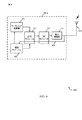
[0036]図2は、本システム及び方法による、eNB105−aの一実施形態を示すブロック図200である。eNB105−aは、図1に示されるeNB105の一例であり得る。eNB105−aは、受信機モジュール205、キャリブレーティングモジュール210、及び送信機モジュール215を含み得る。これらの構成要素の各々は、互いに通信し得る。
[0036] FIG. 2 is a block diagram 200 illustrating one embodiment of an eNB 105-a in accordance with the present systems and methods. The eNB 105-a may be an example of the
[0037]eNB105−aのこれらの構成要素は、個別にまたはまとめて、ハードウェアの適用可能な機能のいくつかまたはすべてを実施するように適合された、1つ又は複数の特定用途向け集積回路(ASIC)で実装され得る。代替的に、機能は、1つ又は複数の集積回路上の、1つ又は複数の他の処理ユニット(又はコア)によって、実施され得る。他の実施形態では、他のタイプの集積回路(例えば、構造化/プラットフォームASIC、フィールドプログラマブルゲートアレイ(FPGA)、及び他のセミカスタムIC)が使用され得、これらは、当該技術分野で知られている任意の方法でプログラムされ得る。各ユニットの機能はまた、1つ又は複数の汎用プロセッサ又は特定用途向けプロセッサによって実行されるようにフォーマットされた、メモリに組み込まれた命令により、全体的又は部分的に、実装され得る。 [0037] These components of the eNB 105-a may be individually or collectively adapted to implement some or all of the applicable functions of the hardware, one or more application specific integrated circuits (ASIC) may be implemented. Alternatively, the functions may be performed by one or more other processing units (or cores) on one or more integrated circuits. In other embodiments, other types of integrated circuits (eg, structured / platform ASICs, field programmable gate arrays (FPGAs), and other semi-custom ICs) may be used and are known in the art. Can be programmed in any way. The functionality of each unit may also be implemented in whole or in part by instructions embedded in memory formatted to be executed by one or more general purpose or application specific processors.
[0038]1つの構成では、受信機モジュール205は、セルラー受信機を含み、UE115からの送信を受信し得る。トラフィックデータ、制御信号等は、1つ又は複数のUE115に対し、送信機モジュール215を介して送信され得る。一実施形態では、キャリブレーティングモジュール210は、サブフレームのキャリブレーションシンボルを生成し得る。サブフレームは、LTEダウンリンク無線フレーム内からのサブフレームであり得る。1つの構成では、キャリブレーションシンボルは、予め定義された波形を含み得る。いくつかのケースでは、波形は、受信機モジュール205及び/又はキャリブレーティングモジュール210によって、専用のフィードバック受信経路を通じるなどして、受信され得る。波形は、eNB105−aの送信経路をキャリブレートするためにモジュール210によって使用され得る。キャリブレーティングモジュール210に関する追加の詳細が、以下に説明される。
[0038] In one configuration,
[0039]図3は、本システム及び方法による、eNB105−bの一実施形態を示すブロック図300である。eNB105−bは、図1及び/又は図2に示されるeNB105の一例であり得る。eNB105−bは、受信機モジュール205、キャリブレーティングモジュール210−a、及び送信機モジュール215を含み得る。これらの構成要素の各々は、互いに通信し得る。
[0039] FIG. 3 is a block diagram 300 illustrating one embodiment of an eNB 105-b according to the present systems and methods. The eNB 105-b may be an example of the
[0040]eNB105−bのこれらの構成要素は、個別にまたはまとめて、ハードウェアの適用可能な機能のいくつかまたはすべてを実施するように適合された、1つ又は複数の特定用途向け集積回路(ASIC)で実装され得る。代替的に、機能は、1つ又は複数の集積回路上の、1つ又は複数の他の処理ユニット(又はコア)によって、実施され得る。他の実施形態では、他のタイプの集積回路(例えば、構造化/プラットフォームASIC、フィールドプログラマブルゲートアレイ(FPGA)、及び他のセミカスタムIC)が使用され得、これらは、当該技術分野で知られている任意の方法でプログラムされ得る。各ユニットの機能はまた、1つ又は複数の汎用プロセッサ又は特定用途向けプロセッサによって実行されるようにフォーマットされた、メモリに組み込まれた命令により、全体的又は部分的に、実装され得る。 [0040] These components of the eNB 105-b are individually or collectively adapted to implement some or all of the applicable functions of the hardware, one or more application specific integrated circuits (ASIC) may be implemented. Alternatively, the functions may be performed by one or more other processing units (or cores) on one or more integrated circuits. In other embodiments, other types of integrated circuits (eg, structured / platform ASICs, field programmable gate arrays (FPGAs), and other semi-custom ICs) may be used and are known in the art. Can be programmed in any way. The functionality of each unit may also be implemented in whole or in part by instructions embedded in memory formatted to be executed by one or more general purpose or application specific processors.
[0041]1つの構成では、受信機モジュール205及び送信機モジュール215は、すでに説明したように、様々な受信動作及び送信動作を実施し得る。一実施形態では、キャリブレーティングモジュール210−aは、送信経路キャリブレーションモジュール305、及び送信経路選択モジュール310を含み得る。
[0041] In one configuration, the
[0042]送信経路キャリブレーションモジュール305は、専用のフィードバック受信経路を通じて、ダウンリンク送信を監視し得る。モジュール305は、専用のフィードバック受信経路を介して、ダウンリンクチャネルにおけるサブフレームの少なくとも一部を受信し得る。一実施形態では、サブフレームの少なくとも一部は、予め定義された波形を含むキャリブレーションシンボルを含み得る。送信経路キャリブレーションモジュール305は、eNB105−bの送信経路をキャリブレートするために、予め定義された波形を使用し得る。
[0042] The transmit
[0043]1つの構成では、送信経路選択モジュール310は、eNB105−bのいくつかのアンテナからのダウンリンク送信を監視し得る。モジュール310は、専用のフィードバック受信経路を通じて、これらの送信を監視し得る。選択モジュール310は、受信経路を介して、サブフレームの少なくとも一部を受信し得る。サブフレームは、第1のスロットを含み得る。第1のスロットは、少なくとも1つのキャリブレーションシンボルを含み得る。第1のキャリブレーションシンボルは、第1の予め定義された波形を含み得る。1つの構成では、選択モジュール310は、第1のアンテナの第1の送信経路を選択し得る。選択された第1の送信経路は、第1の予め定義された波形を使用して、サブフレームの第1のスロットの期間中にキャリブレートされ得る。
[0043] In one configuration, the transmission
[0044]サブフレームの第2のスロットの期間中に、送信経路選択モジュール310は、eNB105−bの第2のアンテナの第2の送信経路を選択し得る。第2のスロットは、少なくとも1つのキャリブレーションシンボルを含み得る。このシンボルは、第2の予め定義された波形を含み得る。第1の波形及び第2の波形は、異なるものであり得、又はこれらは同じものであり得る。1つの例では、モジュール310によって選択される第2の送信経路は、サブフレームの第2のスロットの期間中に、第2の予め定義された波形を使用してキャリブレートされ得る。送信経路選択モジュール310は、ダウンリンクサブフレームの異なるスロットの少なくとも一部の期間中にキャリブレートすべき異なる送信経路を選択し続け得る。マルチプルな無線アンテナ及び単一のフィードバックパイプについて、異なる送信経路からの特定のキャリブレーションシンボルがサンプリングされ得る。1つの例として、2つのアンテナポートに関しては、サブフレームのスロット0のシンボル1、2、3、4、5、6が、アンテナポート0についてサンプリングされ、サブフレームのスロット1の対応するシンボルが、アンテナポート1について送信経路をキャリブレートするためにサンプリングされ得る。
[0044] During the second slot of the subframe, the transmission
[0045]図4は、送信経路キャリブレーションモジュール305−aの一実施形態を示すブロック図400である。モジュール305−aは、図3に説明されたモジュール305の一例であり得る。1つの例では、モジュール305−aは、eNB105の送信経路に含まれる、様々な構成要素を含み得る。例えば、送信経路モジュール305−aは、ベースバンド変調器405、推定モジュール410、デジタルフロントエンド(DFE)モジュール415、無線周波数(RF)モジュール420、及び電力増幅器(PA)425を含み得る。
[0045] FIG. 4 is a block diagram 400 illustrating one embodiment of a transmission path calibration module 305-a. Module 305-a may be an example of
[0046]1つの構成では、ベースバンド変調器405は、ベースバンド信号を変調し、変調された信号は、DFEモジュール415に渡され得る。1つの例では、ベースバンド変調器405は、DFEモジュール415の一部であり得る。DFEモジュール415は、変調されたベースバンド信号に対して様々なデジタル信号処理(DSP)技法を実施し、デジタル信号は、アナログ信号に変換され、RFモジュール420に渡され得る。RFモジュール420は、アナログ信号をフィルタリングし、PA425は、信号がeNB105のアンテナ435を介して送信される前に、アナログ信号を増幅し得る。一実施形態では、専用のフィードバック受信経路430は、PA425の出力のところに存在し得る。フィードバック経路430は、推定モジュール410に入力され得る。推定モジュール410は、eNB105の送信経路の様々な障害を推定するために、専用のフィードバック経路430を使用し得る。モジュール410は、PA425の線形化のためのデジタルプリディストーション係数を算出し得る。一実施形態では、算出された係数は、ベースバンド変調器405及びDFEモジュール415に転送され得る。いくつかのケースでは、キャリブレーションが実施されるために、UE115との接続が確立される必要はないことに留意されたい。1つの例では、専用のフィードバック受信経路430が推定モジュール410に入力され得るので、eNB105は、送信経路キャリブレーションのためにUE115から何も受信する必要がない。送信経路キャリブレーションモジュール305−aに関する詳細が、以下に説明される。
[0046] In one configuration, the
[0047]図5は、送信経路キャリブレーションモジュール305−bの1つの構成を示すブロック図である。キャリブレーションモジュール305−bは、図3及び/又は図4に説明されたキャリブレーションモジュール305の一例であり得る。1つの例では、モジュール305−bは、eNB105の送信経路に含まれる様々な構成要素を含み得る。例えば、送信経路モジュール305−bは、ベースバンド変調器405−a、推定モジュール410−a、DFEモジュール415−a、デジタル−アナログ変換器(DAC)545、RFモジュール420−a、PA425、及び専用のフィードバックパイプ560を含み得る。
[0047] FIG. 5 is a block diagram illustrating one configuration of the transmission path calibration module 305-b. The calibration module 305-b may be an example of the
[0048]1つの構成では、ベースバンド変調器405−aは、波形生成モジュール505を含み得る。モジュール505は、eNB105の送信経路をキャリブレートするために使用され得る、少なくとも1つの予め定義された波形を生成し得る。1つの例では、波形生成モジュール505は、eNB105のメモリに事前に記憶された1つ又は複数の波形を取り出し得る。1つの構成では、波形は、サブフレームのキャリブレーションシンボルの期間中に、eNB105の送信経路に通され得る。サブフレームは、LTEダウンリンク送信に使用される無線フレーム内のサブフレームであり得る。
[0048] In one configuration, the baseband modulator 405-a may include a
[0049]一実施形態では、予め定義された波形は、eNB105の送信経路の様々なアスペクトをキャリブレートするように使用され得る。送信経路は、アナログ及びRF成分(例えば、同相/直交(I/Q)変調器555、アナログフィルタ550、PA425等)によって発生させられ得る様々な障害を補償するようにキャリブレートされ得る。これらの障害は、I/Q構成要素の利得と位相との間のミスマッチ、局部発振器(LO)の漏れ、利得変動、及び非線形効果を含み得る。いくつかの実施形態では、障害は、熱的及び時間的変動にさらされ得る。結果として、予め定義された波形が、eNBの通常のシステム動作中に送信経路をキャリブレートするために使用され得る。送信経路のキャリブレーションは、周期的間隔、又は非周期的間隔で起こり得る。組み込まれたフィードバック受信経路は、送信経路をキャリブレートするために使用され得る。専用のフィードバックパイプ560は、フィードバック受信経路を提供し得る。推定モジュール410−aは、フィードバックを受信し得る。一実施形態では、障害推定モジュール510は、フィードバック受信経路から送信経路の様々な障害を推定し得る。係数推定モジュール515は、送信経路をキャリブレートするために係数を推定し得る。推定された係数は、eNB105のDFEモジュール415−a及びベースバンド変調器405−aに渡され得る。DFEモジュール415−aは、サンプルレート変換器520、デジタルプリディストーションモジュール530、同相/直交(I/Q)インバランス補償モジュール535、及び送信機等化器540を含み得る。
[0049] In one embodiment, the pre-defined waveform may be used to calibrate various aspects of the transmission path of the
[0050]1つの例では、キャリブレーションシンボルは、I/Qインバランスを推定するために使用される波形を搬送し得る。一実施形態では、キャリブレーションシンボルは、(推定モジュール410−a等の)受信機にアプリオリに知られている、1つ又はいくつかのトーンを搬送し得る。1つの構成では、スペクトルにおける単一のトーンは、キャリブレーションシンボルの期間中に送信され得る。障害推定モジュール510は、送信経路内のI/Qインバランスによって引き起こされる、1つまたは複数のイメージ(an image or images)を推定するために、予め定義された波形を使用し得る。例えば、スペクトルの下側バンドにおける1つ又は複数のイメージの推定が生成され得る。1つの構成では、イメージ(1つまたは複数)は、eNB105の送信経路内のI/Qインバランスの結果であり得る。I/Qインバランスは、推定された1つ又は複数のイメージに少なくとも部分的に基づいて、障害推定モジュール510によって推定され得る。
[0050] In one example, a calibration symbol may carry a waveform used to estimate I / Q imbalance. In one embodiment, the calibration symbols may carry one or several tones that are known a priori to the receiver (such as estimation module 410-a). In one configuration, a single tone in the spectrum may be transmitted during a calibration symbol. The
[0051]別の例では、キャリブレーションシンボルは、最大送信電力シンボルの統計的表現を提供する最適化された波形と共にロードされ得る。例えば、波形は、PA425が伝達するように設計された、全チャネルバンド幅にわたる最大電力又は最適電力を表し得る。これらの波形は、PA425の線形化のためのプリディストーション推定のために有用であり得る。1つの構成では、波形は、正確な量のディストーションを受け得る。結果として、係数が、DFE415−aのデジタルプリディストーションモジュール530のために、係数推定モジュール515によって推定され得る。
[0051] In another example, calibration symbols may be loaded with an optimized waveform that provides a statistical representation of the maximum transmit power symbol. For example, the waveform may represent the maximum or optimal power over the full channel bandwidth that
[0052]PA425によって引き起こされる障害を推定するために使用される波形は、PA425の既知の直線性の最大推定を提供するようにアプリオリに構築され得る。通常、デジタルプリディストーションにより、基準の役割を果たす、送信された、プリディストーションされた波形が、サンプリングされ得る。PA425の出力も、サンプリングされ得る。PA出力は、その後、プリディストーション係数を推定するために、プリディストーションされた基準と比較され得る。本システム及び方法は、予め定義された波形が推定モジュール410−aにアプリオリに知られている場合があるので、送信経路のサンプリングを回避し得る。1つの構成では、予め定義された波形は、eNB105のメモリに予め記憶され得る。結果として、eNB105のシステム動作中に、プリディストーションされた波形をサンプリングする必要性は、生じない。一実施形態では、キャリブレーションシンボルは、異なるタイプの障害を検出するために、サブフレーム及び/又はフレーム内で変化し得る。例えば、サブフレーム内の1つのキャリブレーションシンボルは、I/Qインバランスを検出するために使用され、サブフレーム内の第2のキャリブレーションシンボルは、PAによって引き起こされる障害を検出するために使用され得る。
[0052] The waveform used to estimate the impairment caused by PA425 may be constructed a priori to provide a maximum estimate of the known linearity of PA425. Typically, with digital predistortion, a transmitted predistorted waveform that serves as a reference can be sampled. The output of PA425 can also be sampled. The PA output can then be compared to predistorted criteria to estimate the predistortion factor. The present system and method may avoid sampling of the transmission path because the predefined waveform may be known a priori to the estimation module 410-a. In one configuration, the predefined waveform may be stored in advance in the memory of the
[0053]1つの構成では、メディアアクセス制御(MAC)データ通信プロトコル副層は、キャリブレーションの目的で予め定義された波形を搬送するために使用されるこれらのキャリブレーションシンボルを認識しない可能性があり得る。結果として、MAC層は、サブフレームの期間中に1つ又は複数のUE115にダウンリンクデータを継続的に送信し得る。一実施形態では、物理(PHY)層は、1つ又は複数の予め定義された波形によりダウンリンクデータを搬送するサブフレームのデータシンボルをオーバーライドし得る。結果として、UE115は、ダウンリンク情報を受信しない場合があり得る。UE115は、eNB105に、否定応答(NACK)を送信し得る。eNB105は、ハイブリッド自動再送要求(HARQ)手順に従って、ダウンリンクデータを再送信し得る。一実施形態では、eNB105は、PHY層が予め定義された波形によりデータシンボルをオーバーライドしたことを認識することなく、HARQメカニズムに従ってダウンリンクデータを再送信し得る。
[0053] In one configuration, the media access control (MAC) data communication protocol sublayer may not recognize these calibration symbols that are used to carry a predefined waveform for calibration purposes. possible. As a result, the MAC layer may continuously transmit downlink data to one or
[0054]1つの構成では、MAC層は、送信経路の周期的なキャリブレーションを認識し得る。1つの例では、MACスケジューラは、キャリブレーション目的で使用されるサブフレームの期間中にUE115に対して事前に割り当てられたダウンリンクリソースを保存し得る。しかし、サブフレームの制御シンボルは、UE115に対してこれらのダウンリンクリソースのゼロ割当てをシグナリングし得る。結果として、UEは、このサブフレームにおけるダウンリンクトラフィックを監視しないようにシグナリングされ得る。制御シンボルは、ダウンリンク基準信号(RS)(すなわち、パイロット信号)及びダウンリンク制御チャネル(DCCH)の一方又は両方を含み得るか、又はこれらに関連付けられ得る。DCCHの例は、物理ダウンリンク制御チャネル(PDCCH)、物理制御フォーマットインジケータチャネル(PCFICH)、及び物理ハイブリッドARQインジケータチャネル(PHICH)を含み得るが、これらに限定されない。
[0054] In one configuration, the MAC layer may recognize periodic calibration of the transmission path. In one example, the MAC scheduler may save downlink resources pre-assigned to
[0055]1つの構成では、第1サブフレームのキャリブレーションシンボル及び制御シンボルが送信され得る。キャリブレーションシンボルは、以上で説明されたように、キャリブレーションのための予め定義された波形を含み得る。制御シンボルは、ダウンリンク基準信号及び/又はダウンリンク制御チャネルを含み得るか、又はこれらに関連付けられ得る。いくつかのケースでは、ダウンリンク基準信号は、LTEセル固有基準信号など、標準的なパイロットシンボルを含み得る。セル固有基準信号は、送信アンテナポートの数ならびに送信モードに依存し得る。様々な実施形態では、ダウンリンク基準信号は、セル固有基準信号、復調基準信号、チャネル状態情報(CSI)基準信号、ポジショニング基準信号、及び/又はマルチメディアブロードキャストマルチキャストサービス単一周波数ネットワーク(MBSFN)基準信号を含み得る。一実施形態では、特定の数の追加のシンボルが、制御シンボルに続いて送信され得る。1つの構成では、少なくとも3つの追加のシンボルが送信され得る。これらの追加のシンボルは、データサブキャリアがRSトーンでインターリーブされた、データOFDMシンボルであり得る。1つの例では、第2のサブフレームは、ダウンリンクトラフィックデータを送信するために、制御シンボル及びデータシンボルを含み得る。第2のサブフレームは、第1のサブフレームとは異なり得る。一実施形態では、制御シンボルは、第1のサブフレームから第2のサブフレームに、変化しないままであり得る。 [0055] In one configuration, calibration symbols and control symbols for the first subframe may be transmitted. The calibration symbol may include a predefined waveform for calibration, as described above. The control symbols may include or be associated with a downlink reference signal and / or a downlink control channel. In some cases, the downlink reference signal may include standard pilot symbols, such as LTE cell specific reference signals. The cell specific reference signal may depend on the number of transmit antenna ports as well as the transmission mode. In various embodiments, the downlink reference signal is a cell specific reference signal, a demodulation reference signal, a channel state information (CSI) reference signal, a positioning reference signal, and / or a multimedia broadcast multicast service single frequency network (MBSFN) reference. A signal may be included. In one embodiment, a certain number of additional symbols may be transmitted following the control symbols. In one configuration, at least three additional symbols may be transmitted. These additional symbols may be data OFDM symbols with data subcarriers interleaved with RS tones. In one example, the second subframe may include control symbols and data symbols to transmit downlink traffic data. The second subframe may be different from the first subframe. In one embodiment, the control symbols may remain unchanged from the first subframe to the second subframe.
[0056]図6は、基地局(eNB)105−c及びモバイルデバイス(UE)115−aを含む、MIMO通信システム600のブロック図である。このシステム600は、図1のシステム100の態様を示し得る。基地局105−cは、アンテナ634−a〜634−xを備え、モバイルデバイス115−aは、アンテナ652−a〜652−nを備え得る。システム600では、基地局105−cは、同時にマルチプルな通信リンクを介してデータを送信可能であり得る。各通信リンクは、「層」と呼ばれ、通信リンクの「ランク」は、通信に使用される層の数を示し得る。例えば、基地局105−cが2つの「層」を送信する2×2MIMOシステムでは、基地局105−cとUE115−aとの間の通信リンクのランクは、2である。
[0056] FIG. 6 is a block diagram of a
[0057]基地局105−cにおいて、送信プロセッサ620は、データソースからデータを受信し得る。送信プロセッサ620は、データを処理し得る。送信プロセッサ620はまた、基準信号及びセル固有基準信号を生成し得る。送信(TX)MIMOプロセッサ630は、適用可能であれば、データシンボル、制御シンボル、及び/又は基準シンボルに対して、空間処理(例えば、プリコーディング)を実施し、送信変調器632−a〜632−xに出力シンボルストリームを提供し得る。各変調器632は、出力サンプルストリームを取得するために、(例えば、OFDM等のための)それぞれの出力シンボルストリームを処理し得る。各変調器632はさらに、ダウンリンク信号を取得するために、出力サンプルストリームを処理(例えば、アナログに変換、増幅、フィルタリング、及びアップコンバート)し得る。1つの例では、変調器632−a〜632−xのダウンリンク信号は、それぞれ、アンテナ634−a〜アンテナ634−xを介して送信され得る。
[0057] At base station 105-c, transmit
[0058]モバイルデバイス115−aでは、モバイルデバイスアンテナ652−a〜652−nが、基地局105−cから、ダウンリンク信号を受信し、それぞれ、復調器654−a〜654−nに対して、受信された信号を提供し得る。各復調器654は、入力サンプルを取得するために、それぞれの受信された信号を調整(例えば、フィルタリング、増幅、ダウンコンバート、及びデジタル化)し得る。各復調器654はさらに、受信されたシンボルを取得するために、(例えば、OFDM等のための)入力サンプルを処理し得る。MIMO検出器656は、復調器654−a〜654−nのすべてから、受信されたシンボルを取得し、適用可能であれば、受信されたシンボルに対してMIMO検出を実施し、検出されたシンボルを提供し得る。受信プロセッサ658は、検出されたシンボルを処理(例えば、復調、デインターリーブ、及び復号)し、モバイルデバイス115−aのための復号されたデータを、データ出力に提供し、復号された制御情報を、プロセッサ680、又はメモリ682に提供し得る。一実施形態では、UE115−aは、ダウンリンクチャネルにおけるダウンリンク送信を監視し得る。UE115−aは、ダウンリンクチャネルにおける第1のサブフレームを受信し得る。サブフレームは、予め定義された波形を含むキャリブレーションシンボルを含み得る。1つの構成では、UE115−aは、基準信号及びダウンリンク制御チャネルを含む、1つ又は複数の制御シンボルを受信し得る。制御シンボルは、サブフレームのダウンリンクリソースのゼロ割当てを、UE115−aに対してシグナリングし得る。1つの例では、UE115−aは、ダウンリンクリソースの割り当てをシグナリングする制御シンボルを含む、第2のサブフレームを受信し得る。第2のサブフレームは、UE115−aのためのトラフィックデータを含むデータシンボルを含み得る。
[0058] In mobile device 115-a, mobile device antennas 652-a through 652-n receive the downlink signals from base station 105-c and respectively to demodulators 654-a through 654-n. A received signal may be provided. Each
[0059]アップリンクでは、モバイルデバイス115−aにおいて、送信プロセッサ664が、データソースからのデータを受信し、処理し得る。送信プロセッサ664はまた、基準信号のための基準シンボルを生成し得る。送信プロセッサ664からのシンボルは、適用可能であれば、送信MIMOプロセッサ666によってプリコードされ、(例えば、SC−FDMA等のための)復調器654−a〜654−nによってさらに処理され、基地局105−cから受信された送信パラメータ(例えば、割り当てられたリソースの識別)に従って基地局105−cに送信され得る。基地局105−cにおいては、モバイルデバイス115−aからのアップリンク信号は、アンテナ634によって受信され、復調器632によって処理され、適用可能であれば、MIMO検出器636によって検出され、受信プロセッサによってさらに処理され得る。受信プロセッサ638は、データ出力及びプロセッサ640に対して、復号されたデータを提供し得る。プロセッサ640は、キャリブレーティングモジュール210−bを含み得る。キャリブレーティングモジュール210−bは、図2及び/又は図3を参照して説明された、モジュール210の一例であり得る。キャリブレーティングモジュール210−bは、ダウンリンクチャネルにおける送信のためにサブフレームの少なくとも1つのキャリブレーションシンボルを生成し得る。モジュール210−bはさらに、サブフレームの少なくとも1つのキャリブレーションシンボルを送信し得る。キャリブレーションシンボルは、基地局105−cの送信経路をキャリブレートするために、予め定義された波形を含み得る。
[0059] On the uplink, at the mobile device 115-a, a transmit
[0060]モバイルデバイス115−aの構成要素は、個別にまたはまとめて、ハードウェアの適用可能な機能のいくつかまたはすべてを実施するように適合された、1つ又は複数の特定用途向け集積回路(ASIC)で実装され得る。上述のモジュールの各々は、システム600の動作に関連した1つ又は複数の機能を実施するための手段であり得る。同様に、基地局105−cの構成要素は、個別にまたはまとめて、ハードウェアの適用可能な機能のいくつかまたはすべてを実施するように適合された、1つ又は複数の特定用途向け集積回路(ASIC)で実装され得る。上述の構成要素の各々は、システム600の動作に関連した、1つ又は複数の機能を実施するための手段であり得る。
[0060] The components of the mobile device 115-a are one or more application specific integrated circuits adapted to perform some or all of the applicable functions of the hardware, individually or collectively. (ASIC) may be implemented. Each of the modules described above may be a means for performing one or more functions related to the operation of
[0061]図7は、基地局105の送信経路をキャリブレートする方法700の一例を示すフローチャートである。分かりやすいように、方法700は、図1、図2、図3、及び/又は図6に示される基地局105のうちの1つを参照して、以下に説明される。1つの実装形態では、キャリブレーティングモジュール210は、以下に説明される機能を実施するように基地局105の機能的要素を制御するために、コードの1つ又は複数のセットを実行し得る。
FIG. 7 is a flowchart illustrating an
[0062]一実施形態では、ブロック705において、サブフレームのキャリブレーションシンボルが生成され得る。ブロック710では、サブフレームのキャリブレーションシンボルは、ダウンリンクチャネルにおいて送信され得る。1つの構成では、キャリブレーションシンボルは、1つ又は複数の予め定義された波形を含み得る。波形は、基地局の送信経路をキャリブレートするために使用され得る。ブロック715において、サブフレームの少なくとも一部が受信され得る。1つの構成では、サブフレームの少なくとも一部が、専用のフィードバック受信経路を通じて受信され得る。サブフレームの少なくとも一部は、キャリブレーションシンボルを含み得る。
[0062] In one embodiment, at
[0063]したがって、方法700は、ワイヤレス通信システムにおいて基地局の送信経路をキャリブレートすることを提供し得る。方法700は、単なる1つの実装形態であり、方法700の動作は、他の実装形態が可能であるように、再配置され、あるいは他の何らかの形で修正され得ることに留意されたい。
[0063] Accordingly, the
[0064]図8は、基地局105の送信経路をキャリブレートする方法800の一例を示すフローチャートである。分かりやすいように、方法800は、図1、図2、図3、及び/又は図6に示される基地局105のうちの1つを参照して、以下に説明される。1つの実装形態では、キャリブレーティングモジュール210は、以下に説明される機能を実施するように基地局105の機能的要素を制御するために、コードの1つ又は複数のセットを実行し得る。
FIG. 8 is a flowchart illustrating an
[0065]一実施形態では、ブロック805において、サブフレームのキャリブレーションシンボルが生成され得る。キャリブレーションシンボルは、基地局105の送信経路をキャリブレートするために使用される、予め定義された波形を含み得る。ブロック810において、サブフレームの制御シンボルが生成され得る。制御シンボルは、1つ又は複数の基準信号及び/又はダウンリンク制御チャネル(例えば、PDCCH、PCFICH、PHICH)を含み得るか、又はこれらに関連付けられ得る。ブロック815において、制御シンボルが送信され得る。制御シンボルは、サブフレームの期間中に、ダウンリンクリソースのゼロ割当てをモバイルデバイスにシグナリングし得る。ブロック820において、サブフレームのキャリブレーションシンボルは、ダウンリンクチャネルにおいてされ得る。1つの構成では、キャリブレーションシンボルは、1つ又は複数の予め定義された波形を含み得る。波形は、基地局の送信経路をキャリブレートするために使用され得る。ブロック825において、サブフレームの少なくとも一部が受信され得る。1つの構成では、サブフレームの少なくとも一部が、専用のフィードバック受信経路を通じて受信され得る。サブフレームの少なくとも一部は、キャリブレーションシンボルを含み得る。
[0065] In an embodiment, at
[0066]したがって、方法800は、ワイヤレス通信システムにおいて、基地局の送信経路をキャリブレートすることを提供し得る。方法800は、単なる1つの実装形態であり、方法800の動作は、他の実装形態が可能であるように、再配置され、あるいは他の何らかの形で修正され得ることに留意されたい。
[0066] Accordingly, the
[0067]図9は、基地局105の送信経路をキャリブレートする方法900の一例を示すフローチャートである。分かりやすいように、方法900は、図1、図2、図3、及び/又は図6に示される基地局105のうちの1つを参照して、以下に説明される。1つの実装形態では、キャリブレーティングモジュール210は、以下に説明される機能を実施するための、基地局105の機能的要素を制御するために、コードの1つ又は複数のセットを実行し得る。
FIG. 9 is a flowchart illustrating an
[0068]一実施形態では、ブロック905において、サブフレームのキャリブレーションシンボルが生成され得る。キャリブレーションシンボルは、ダウンリンクチャネルにおける送信のために生成され得る。このシンボルは、予め定義された波形を含み得る。波形は、送信経路をキャリブレートし、基地局105の送信経路において様々なRFコンポーネントによって引き起こされる障害を補償するために使用され得る。ブロック910において、ダウンリンクデータは、サブフレームの少なくとも1つのデータシンボルの期間中に、モバイルデバイスに対してMAC層において送信され得る。ブロック915では、ダウンリンクデータは、PHY層において予め定義された波形で置き換えられ得る。ブロック920では、サブフレームの少なくとも一部が受信され得る。1つの構成では、サブフレームの少なくとも一部が、専用のフィードバック受信経路を通じて受信され得る。サブフレームの少なくとも一部は、キャリブレーションシンボルを含み得る。NACKがモバイルデバイスから受信されるかどうかに関する決定が、ブロック925でなされ得る。決定ブロック925が、ブロック915及び/又はブロック910の結果であり得ることに留意されたい。しかし、いくつかのケースでは、それは、専用のフィードバック受信経路を通じて受信され、別のデバイスからの応答を必要としないという理由などで、しばしばNACKが受信される前にサブフレームの少なくとも一部が受信されるので、ブロック920の後に表され得る。NACKが受信されないと決定された場合、新たなダウンリンクデータが、ブロック930で、MAC層においてモバイルデバイスに対して送信され得る。しかし、NACKが受信されると決定された場合、ブロック935で、ダウンリンクデータは、HARQ手順に従ってMAC層において再送信され得る。
[0068] In one embodiment, at
[0069]したがって、方法900は、ダウンリンクトラフィックを、送信経路のキャリブレーションのために使用され得る予め定義された波形で置き換えることにより、ワイヤレス通信システムにおける基地局の送信経路をキャリブレートすることを提供し得る。方法900は、単なる1つの実装形態であり、方法900の動作は、他の実装形態が可能であるように、再配置され、あるいは他の何らかの形で修正され得ることに留意されたい。
[0069] Accordingly, the
[0070]様々な開示された実施形態のいくつかに対応し得る通信ネットワークは、層状プロトコルスタックに従って動作するパケットベースのネットワークであり得る。例えば、ベアラ又はパケットデータコンバージェンスプロトコル(PDCP)層での通信は、IPベースであり得る。無線リンク制御(RLC)層は、論理チャネルを介して通信するように、パケットセグメンテーション及びリアセンブリを実施し得る。媒体アクセス制御(MAC)層は、トランスポートチャネルへの論理チャネルのプライオリティ処理及び多重化を実施し得る。MAC層はまた、リンク効率を改善するため、MAC層における再送信を提供するために、ハイブリッドARQ(HARQ)を使用し得る。物理層では、トランスポートチャネルは、物理チャネルにマッピングされ得る。 [0070] A communication network that may accommodate some of the various disclosed embodiments may be a packet-based network that operates according to a layered protocol stack. For example, communication at the bearer or packet data convergence protocol (PDCP) layer may be IP based. A radio link control (RLC) layer may perform packet segmentation and reassembly to communicate over logical channels. The medium access control (MAC) layer may perform priority processing and multiplexing of logical channels to transport channels. The MAC layer may also use hybrid ARQ (HARQ) to provide retransmission at the MAC layer to improve link efficiency. At the physical layer, transport channels can be mapped to physical channels.
[0071]添付の図面に関連して以上に記載した詳細な説明は、例示的な実施形態を説明しており、実現され得る、又は特許請求の範囲内にある実施形態のみを表現するものではない。本明細書を通して使用される「例示的な」という用語は、「例、事例、又は説明として役立つ」ということを意味しており、「好ましい」、又は「他の実施形態よりも有用」を意味するものではない。詳細な説明は、説明された技法の理解を提供することを目的とした、具体的な詳細を含んでいる。しかし、これらの技法は、これらの具体的な詳細を有しなくとも実践され得る。いくつかの事例では、よく知られている構造及びデバイスが、説明される実施形態の概念を不明確にすることを避けるために、ブロック図形式で示されている。 [0071] The detailed description set forth above in connection with the accompanying drawings describes exemplary embodiments and is not intended to represent the only embodiments that may be realized or within the scope of the claims. Absent. The term “exemplary” as used throughout this specification means “serving as an example, instance, or illustration” and means “preferred” or “useful over other embodiments”. Not what you want. The detailed description includes specific details for the purpose of providing an understanding of the described techniques. However, these techniques may be practiced without these specific details. In some instances, well-known structures and devices are shown in block diagram form in order to avoid obscuring the concepts of the described embodiments.
[0072]本明細書で説明される技法は、CDMA、TDMA、FDMA、OFDMA、SC−FDMA、及び他のシステム等の、様々なワイヤレス通信システムに使用され得る。「システム」及び「ネットワーク」という用語は、置換可能に使用されることが多い。CDMAシステムは、CDMA2000、ユニバーサル地上無線アクセス(UTRA)等の、無線技術を実装し得る。CDMA2000は、IS−2000規格、IS−95規格、及びIS−856規格をカバーする。IS−2000リリース0及びAは、一般に、CDMA2000 1X、1X等と称される。IS−856(TIA−856)は、一般に、CDMA2000 1xEV−DO、高レートパケットデータ(HRPD)等と称される。UTRAは、広帯域CDMA(WCDMA(登録商標))及びCDMAの他の変形を含む。TDMAシステムは、グローバルシステムフォーモバイルコミュニケーションズ(GSM(登録商標))等の無線技術を実装し得る。OFDMAシステムは、ウルトラモバイルブロードバンド(UMB)、発展型UTRA(E−UTRA)、IEEE802.11(Wi−Fi(登録商標))、IEEE802.16(WiMAX(登録商標))、IEEE802.20、フラッシュ−OFDM等の無線技術を実装し得る。UTRA及びE−UTRAは、ユニバーサルモバイルテレコミュニケーションシステム(UMTS)の一部である。3GPPロング・ターム・エボリューション(LTE)及びLTEアドバンスト(LTE−A)は、E−UTRAを使用するUMTSの新たなリリースである。UTRA、E−UTRA、UMTS、LTE、LTE−A、及びGSM(登録商標)は、「第3世代パートナーシップ計画」(3GPP)という名称の組織からの文書に記載されている。CDMA2000及びUMBは、「第3世代パートナーシップ計画2」(3GPP2)という名称の組織からの文書に記載されている。本明細書で説明される技法は、上述のシステム、及び無線技術、並びに他のシステム、及び無線技術のために使用され得る。しかし、以下の説明は、例示目的で、LTEシステムを説明しており、LTE用語が、以下の説明の多くで使用されるが、本技法は、LTEの用途以外にも適用可能である。 [0072] The techniques described herein may be used for various wireless communication systems such as CDMA, TDMA, FDMA, OFDMA, SC-FDMA, and other systems. The terms “system” and “network” are often used interchangeably. A CDMA system may implement a radio technology such as CDMA2000, Universal Terrestrial Radio Access (UTRA). CDMA2000 covers IS-2000, IS-95, and IS-856 standards. IS-2000 releases 0 and A are commonly referred to as CDMA2000 1X, 1X, etc. IS-856 (TIA-856) is generally referred to as CDMA2000 1xEV-DO, high rate packet data (HRPD), and the like. UTRA includes wideband CDMA (WCDMA) and other variants of CDMA. A TDMA system may implement a radio technology such as Global System for Mobile Communications (GSM). The OFDMA system includes Ultra Mobile Broadband (UMB), Evolved UTRA (E-UTRA), IEEE 802.11 (Wi-Fi (registered trademark)), IEEE 802.16 (WiMAX (registered trademark)), IEEE 802.20, Flash- A wireless technology such as OFDM may be implemented. UTRA and E-UTRA are part of Universal Mobile Telecommunication System (UMTS). 3GPP Long Term Evolution (LTE) and LTE Advanced (LTE-A) are new releases of UMTS that use E-UTRA. UTRA, E-UTRA, UMTS, LTE, LTE-A, and GSM® are described in documents from an organization named “3rd Generation Partnership Project” (3GPP). CDMA2000 and UMB are described in documents from an organization named “3rd Generation Partnership Project 2” (3GPP2). The techniques described herein may be used for the systems and radio technologies mentioned above as well as other systems and radio technologies. However, the following description describes an LTE system for illustrative purposes, and LTE terminology is used in much of the description below, but the techniques are applicable beyond the use of LTE.
[0073]情報及び信号が、様々な異なる技術及び技法のいずれかを使用して表現され得る。例えば、上記の説明を通して参照され得るデータ、命令、コマンド、情報、信号、ビット、シンボル、及びチップが、電圧、電流、電磁波、磁場もしくは磁性粒子、光学場もしくは光学粒子、又はこれらの任意の組合せによって表現され得る。 [0073] Information and signals may be represented using any of a variety of different technologies and techniques. For example, data, instructions, commands, information, signals, bits, symbols, and chips that can be referred to throughout the above description are voltages, currents, electromagnetic waves, magnetic fields or magnetic particles, optical fields or optical particles, or any combination thereof. Can be expressed by:
[0074]本明細書の開示に関連して説明された、様々な例示的なブロック及びモジュールは、汎用プロセッサ、デジタル信号プロセッサ(DSP)、特定用途向け集積回路(ASIC)、フィールドプログラマブルゲートアレイ(FPGA)、もしくは他のプログラマブル論理デバイス、ディスクリートゲート、もしくはトランジスタ論理、ディスクリートハードウェアコンポーネント、又は本明細書で説明される機能を実施するように設計された、これらの任意の組合せを用いて、実装、又は実施され得る。汎用プロセッサは、マイクロプロセッサであり得るが、代替的には、プロセッサは、いかなる従来のプロセッサ、コントローラ、マイクロコントローラ、又はステートマシンであり得る。プロセッサはまた、例えば、DSPとマイクロプロセッサとの組合せ、マルチプルなマイクロプロセッサの組合せ、DSPコアと連携する1つ又は複数のマイクロプロセッサの組合せ、又はいかなる他のこのような構成のような、コンピューティングデバイスの組合せとして、実装され得る。 [0074] Various exemplary blocks and modules described in connection with the disclosure herein include general purpose processors, digital signal processors (DSPs), application specific integrated circuits (ASICs), field programmable gate arrays ( FPGA), or other programmable logic device, discrete gate or transistor logic, discrete hardware components, or any combination thereof designed to perform the functions described herein Or can be implemented. A general purpose processor may be a microprocessor, but in the alternative, the processor may be any conventional processor, controller, microcontroller, or state machine. The processor may also be a computing device such as a combination of a DSP and a microprocessor, a combination of multiple microprocessors, a combination of one or more microprocessors associated with a DSP core, or any other such configuration. It can be implemented as a combination of devices.
[0075]本明細書で説明される機能は、ハードウェア、プロセッサによって実行されるソフトウェア、ファームウェア、又はこれらの任意の組合せに、実装され得る。プロセッサによって実行されるソフトウェアに実装される場合、機能は、コンピュータ可読媒体に、1つ又は複数の命令、又はコードとして、記憶されるか、又は送信され得る。他の例及び実装形態は、本開示、及び添付の請求項の範囲、及び趣旨内にある。例えば、ソフトウェアの性質に起因して、上述の機能は、プロセッサ、ハードウェア、ファームウェア、ハード配線、又はこれらの任意の組合せによって実行されるソフトウェアを使用して、実装されることが可能である。機能を実装する特徴部はまた、機能の一部が異なる物理的位置で実装されるように分散されることを含めて、様々な位置で、物理的に配置され得る。本明細書で使用される場合、特許請求の範囲を含めて、「及び/又は」という用語は、2つ以上の項目のリストで使用される場合、列挙された項目のうちのいずれか1つが、単独で採用される可能性があること、又は、列挙された項目のうち2つ以上任意の組合せが、採用される可能性があることを意味する。例えば、ある構成が、構成要素A、B、及び/又はCを含むものとして説明される場合、この構成は、Aのみ、Bのみ、Cのみ、A及びBの組合せ、A及びCの組合せ、B及びCの組合せ、又はA、B、及びCの組合せを含有することができる。本明細書で使用される場合、特許請求の範囲内を含めて、項目のリスト(例えば、「少なくとも1つの」、又は「1つ又は複数の」等の語句によって前置きされる項目のリスト)内で使用されるような「又は」は、例えば、「A、B、又はCのうちの少なくとも1つ」のリストが、A、又はB、又はC、又はAB、又はAC、又はBC、又はABC(すなわち、A、及びB、及びC)を意味するような、選言的なリストを示している。 [0075] The functions described herein may be implemented in hardware, software executed by a processor, firmware, or any combination thereof. If implemented in software executed by a processor, the functions may be stored on or transmitted over as one or more instructions or code on a computer-readable medium. Other examples and implementations are within the scope and spirit of the present disclosure and the appended claims. For example, due to the nature of software, the functions described above can be implemented using software executed by a processor, hardware, firmware, hardwiring, or any combination thereof. Features that implement functions may also be physically located at various locations, including being distributed such that some of the functions are implemented at different physical locations. As used herein, including the claims, the term “and / or” when used in a list of two or more items, includes any one of the listed items. , May be employed alone, or any combination of two or more of the listed items may be employed. For example, if a configuration is described as including components A, B, and / or C, this configuration may include only A, only B, only C, a combination of A and B, a combination of A and C, A combination of B and C, or a combination of A, B, and C can be included. As used herein, within a list of items, including within a claim (eg, a list of items prefixed by a phrase such as “at least one” or “one or more”) “Or” as used in, for example, a list of “at least one of A, B, or C” is A, B, C, AB, AC, AC, BC, ABC A disjunctive list is shown, meaning (ie, A, B, and C).
[0076]コンピュータ可読媒体は、これらは、ある場所から別の場所へのコンピュータプログラムの転送を容易にするいかなる媒体も含む、コンピュータ記憶媒体と、通信媒体との両方を含む。記憶媒体は、汎用コンピュータ、又は専用コンピュータによってアクセスされることができる、いかなる利用可能な媒体でもあり得る。限定ではなく、1つの例として、コンピュータ可読媒体は、RAM、ROM、EEPROM(登録商標)、CD−ROM、もしくは他の光ディスク記憶装置、磁気ディスク記憶装置、もしくは他の磁気記憶装置、又は命令、もしくはデータ構造の形態で、所望のプログラムコード手段を搬送、もしくは記憶するように使用されることが可能であり、かつ、汎用コンピュータ、もしくは専用コンピュータ、又は汎用プロセッサ、もしくは専用プロセッサによってアクセスされることが可能である、いかなる他の媒体も備えることができる。また、いかなる接続も、適切に、コンピュータ可読媒体と名付けられる。例えば、ソフトウェアが、同軸ケーブル、光ファイバケーブル、ツイストペア、デジタル加入者線(DSL)、又は、赤外線、無線、もしくはマイクロ波等の無線技術を使用して、ウェブサイト、サーバ、又は他の遠隔ソースから送信される場合、同軸ケーブル、光ファイバケーブル、ツイストペア、DSL、又は赤外線、無線、もしくはマイクロ波等のワイヤレス技術は、媒体の定義に含まれる。本明細書で使用される場合、ディスク(disk)、及びディスク(disc)は、コンパクトディスク(disc)(CD)、レーザーディスク(登録商標)(disc)(登録商標)、光ディスク(disc)、デジタル多用途ディスク(disc)(DVD)、フロッピー(登録商標)ディスク(disk)、及びblu−ray(登録商標)ディスク(disc)を含み、ここでは、ディスク(disc)が、レーザーを用いて、光学的にデータを再生するのに対し、ディスク(disk)は、一般に、磁気的にデータを再生する。上記の組合せも、コンピュータ可読媒体の範囲に含まれる。 [0076] Computer-readable media include both computer storage media and communication media including any medium that facilitates transfer of a computer program from one place to another. A storage media may be any available media that can be accessed by a general purpose or special purpose computer. By way of example, and not limitation, computer-readable media includes RAM, ROM, EEPROM®, CD-ROM, or other optical disk storage device, magnetic disk storage device, or other magnetic storage device, or instructions, Or can be used to carry or store the desired program code means in the form of a data structure and be accessed by a general purpose computer, or a special purpose computer, or a general purpose processor, or a special purpose processor. Any other medium can be provided. Also, any connection is properly named a computer-readable medium. For example, the software uses a coaxial cable, fiber optic cable, twisted pair, digital subscriber line (DSL), or wireless technology such as infrared, wireless, or microwave, to a website, server, or other remote source When transmitting from a coaxial cable, fiber optic cable, twisted pair, DSL, or wireless technologies such as infrared, radio, or microwave are included in the definition of the medium. As used herein, a disk and a disc are a compact disc (CD), a laser disc (registered trademark), an optical disc (disc), a digital disc Includes a versatile disc (DVD), a floppy disc, and a blu-ray disc, where the disc is optical using a laser In general, data is reproduced, whereas a disk generally reproduces data magnetically. Combinations of the above are also included within the scope of computer-readable media.
[0077]本開示の上記の説明は、当業者が、本開示を製造、又は利用することを可能にするように提供される。本開示に対する様々な修正は、当業者ならば見てすぐに分かり、かつ本明細書で定義された一般原理は、本開示の趣旨、又は範囲から逸脱することなく、他の変形例に適用され得る。本開示を通して、「例」、又は「例示的」という用語は、例、又は事例を示し、記された例に対するいかなる好ましさを暗示するものでも、又は必要とするものでもない。したがって、本開示は、本明細書で説明される例及び設計に限定されるべきではなく、本明細書に開示される原理及び新たな特徴に一致する、最も広い範囲を与えられるべきである。
以下に、出願当初の特許請求の範囲に記載された発明を付記する。
[C1]
基地局の送信経路をキャリブレートする方法であって、
サブフレームのキャリブレーションシンボルを生成することと、
ダウンリンクチャネルにおいて前記サブフレームの前記キャリブレーションシンボルを送信することと、ここで、前記キャリブレーションシンボルは、前記基地局の前記送信経路をキャリブレートするために、予め定義された波形を備える、
専用のフィードバック受信経路を通じて、前記キャリブレーションシンボルを備える前記サブフレームの少なくとも一部を受信することと
を備える方法。
[C2]
受信された前記キャリブレーションシンボルに少なくとも部分的に基づいて、前記基地局の前記送信経路をキャリブレートすること
をさらに備える、上記C1に記載の方法。
[C3]
前記送信経路をキャリブレートすることは、
受信された前記キャリブレーションシンボルに少なくとも部分的に基づいて、送信経路の障害を推定することと、
前記送信経路の障害に少なくとも部分的に基づいて、補償値を決定することと、
前記補償値に少なくとも部分的に基づいて、前記基地局の前記送信経路をキャリブレートすることと
を備える、上記C2に記載の方法。
[C4]
前記専用のフィードバック受信経路を通じて、前記ダウンリンクチャネルにおける送信を監視すること
をさらに備える、上記C1に記載の方法。
[C5]
前記サブフレームの制御シンボルを送信すること、ここで、前記制御シンボルは、ダウンリンク基準信号及びダウンリンク制御チャネルのうちの一方又は両方に関連付けられている、
をさらに備える、上記C1に記載の方法。
[C6]
ダウンリンク基準信号を備える、少なくとも3つの追加のシンボルを送信すること、
をさらに備える、上記C5に記載の方法。
[C7]
前記ダウンリンク制御チャネルは、物理ダウンリンク制御チャネル(PDCCH)、物理制御フォーマットインジケータチャネル(PCFICH)、又は物理ハイブリッド自動要求インジケータチャネル(PHICH)のうちの少なくとも1つを備える、上記C5に記載の方法。
[C8]
前記サブフレームの期間中にダウンリンクリソースのゼロ割当てを前記モバイルデバイスにシグナリングするために、前記サブフレームの制御シンボルを送信すること
をさらに備える、上記C1に記載の方法。
[C9]
メディアアクセス制御(MAC)層において、前記サブフレームの期間中にモバイルデバイスにダウンリンクデータを送信することと、
物理(PHY)層において、前記ダウンリンクデータを、前記予め定義された波形で置き換えることと、
をさらに備える、上記C1に記載の方法。
[C10]
否定応答(NACK)を受信することと、
前記MAC層において、ハイブリッド自動再送要求(HARQ)手順に従って前記ダウンリンクデータを再送信することと、
をさらに備える、上記C9に記載の方法。
[C11]
前記サブフレームのデータシンボルを、前記キャリブレーションシンボルで置き換えること、
をさらに備える、上記C1に記載の方法。
[C12]
前記予め定義された波形は、
最大有効チャネルバンド幅にわたる、電力増幅器の最大送信電力信号の表現を備える、
上記C1に記載の方法。
[C13]
前記電力増幅器の線形化のためのデジタルプリディストーション係数を推定するために、前記予め定義された波形を使用すること、
をさらに備える、上記C12に記載の方法。
[C14]
前記予め定義された波形は、
前記送信経路の同相/直交(I/Q)インバランスを推定するためのアプリオリトーンを備える、
上記C1に記載の方法。
[C15]
前記送信経路内の、前記I/Qインバランスによって引き起こされるイメージを推定するために、前記予め定義された波形を使用することと、
前記推定されたイメージに少なくとも部分的に基づいて前記I/Qインバランスを推定することと
をさらに備える、上記C14に記載の方法。
[C16]
前記波形の第1のスロットの期間中に、前記基地局の第1のアンテナの第1の送信経路をキャリブレートすることと、ここで、前記第1のスロットは、前記第1のアンテナの前記第1の送信経路をキャリブレートするために、第1の予め定義された波形を搬送するためのキャリブレーションシンボルを備える、
前記波形の第2のスロットの期間中に、前記基地局の第2のアンテナの第2の送信経路をキャリブレートすることと、ここで、前記第2のスロットは、前記第2のアンテナの前記第2の送信経路をキャリブレートするために、第2の予め定義された波形を搬送するためのキャリブレーションシンボルを備える
をさらに備える、上記C1に記載の方法。
[C17]
送信経路をキャリブレートするように構成された基地局であって、
プロセッサと、
前記プロセッサと電子的に通信するメモリと、
前記メモリに記憶された命令と、を備え、前記命令は、
サブフレームのキャリブレーションシンボルを生成することと、
ダウンリンクチャネルにおいて前記サブフレームの前記キャリブレーションシンボルを送信することと、ここで、前記キャリブレーションシンボルは、前記基地局の前記送信経路をキャリブレートするために、予め定義された波形を備える、
専用のフィードバック受信経路を通じて、前記キャリブレーションシンボルを備える前記サブフレームの少なくとも一部を受信することと、
を行うように前記プロセッサによって実行可能である、
基地局。
[C18]
前記命令は、
受信された前記キャリブレーションシンボルに少なくとも部分的に基づいて前記送信経路をキャリブレートすることを行うように、前記プロセッサによって実行可能である、
上記C17に記載の基地局。
[C19]
前記送信経路をキャリブレートすることは、
受信された前記キャリブレーションシンボルに少なくとも部分的に基づいて、送信経路の障害を推定することと、
前記送信経路の障害に少なくとも部分的に基づいて、補償値を決定することと、
前記補償値に少なくとも部分的に基づいて、前記基地局の前記送信経路をキャリブレートすることと
を備える、上記C18に記載の基地局。
[C20]
前記命令は、
前記専用のフィードバック受信経路を通じて、前記ダウンリンクチャネルにおける送信を監視することを行うように、前記プロセッサによって実行可能である、
上記C17に記載の基地局。
[C21]
前記命令は、
前記サブフレームの期間中にダウンリンクリソースのゼロ割当てを前記モバイルデバイスにシグナリングするために、前記サブフレームの制御シンボルを送信することを行うように、前記プロセッサによって実行可能である、
上記C17に記載の基地局。
[C22]
前記命令は、
メディアアクセス制御(MAC)層において、前記サブフレームの期間中にモバイルデバイスにダウンリンクデータを送信することと、
物理(PHY)層において、前記ダウンリンクデータを、前記予め定義された波形で置き換えることとを行うように、前記プロセッサによって実行可能である、上記C17に記載の基地局。
[C23]
前記命令は、
前記サブフレームのデータシンボルを前記キャリブレーションシンボルで置き換えることを行うように、前記プロセッサによって実行可能である、
上記C17に記載の基地局。
[C24]
前記予め定義された波形は、
最大有効チャネルバンド幅にわたる、電力増幅器の最大送信電力信号の表現を備える、
上記C17に記載の基地局。
[C25]
前記命令は、
前記電力増幅器の線形化のためのデジタルプリディストーション係数を推定するために、前記予め定義された波形を使用することを行うように、前記プロセッサによって実行可能である、
上記C24に記載の基地局。
[C26]
前記予め定義された波形は、
前記送信経路の同相/直交(I/Q)インバランスを推定するためのアプリオリトーンを備える、
上記C17に記載の基地局。
[C27]
基地局の送信経路をキャリブレートする装置であって、
サブフレームのキャリブレーションシンボルを生成する手段と、
ダウンリンクチャネルにおいて前記サブフレームの前記キャリブレーションシンボルを送信する手段と、ここで、前記キャリブレーションシンボルは、前記基地局の前記送信経路をキャリブレートするように、予め定義された波形を備える、
専用のフィードバック受信経路を通じて、前記キャリブレーションシンボルを備える前記サブフレームの少なくとも一部を受信する手段と
を備える、装置。
[C28]
前記専用のフィードバック受信経路を通じて、前記ダウンリンクチャネルにおける送信を監視する手段をさらに備える、
上記C27に記載の装置。
[C29]
前記サブフレームのデータシンボルを、前記キャリブレーションシンボルで置き換える手段をさらに備える、
上記C27に記載の装置。
[C30]
基地局の送信経路をキャリブレートするためのコンピュータプログラム製品であって、
サブフレームのキャリブレーションシンボルを生成することと、
ダウンリンクチャネルにおいて前記サブフレームの前記キャリブレーションシンボルを送信することと、ここで、前記キャリブレーションシンボルは、前記基地局の前記送信経路をキャリブレートするために、予め定義された波形を備え、
専用のフィードバック受信経路を通じて、前記キャリブレーションシンボルを備える前記サブフレームの少なくとも一部を受信することと、
を行うようにプロセッサによって実行可能な命令を記憶する非一時的なコンピュータ可読媒体を備える、コンピュータプログラム製品。
[0077] The above description of the disclosure is provided to enable any person skilled in the art to make or use the disclosure. Various modifications to this disclosure will be readily apparent to those skilled in the art, and the generic principles defined herein may be applied to other variations without departing from the spirit or scope of this disclosure. obtain. Throughout this disclosure, the term “example” or “exemplary” indicates an example or instance and does not imply or require any preference for the described example. Accordingly, the present disclosure should not be limited to the examples and designs described herein, but should be accorded the widest scope consistent with the principles and new features disclosed herein.
The invention described in the scope of claims at the beginning of the application will be appended.
[C1]
A method for calibrating a transmission path of a base station,
Generating calibration symbols for subframes;
Transmitting the calibration symbol of the subframe in a downlink channel, wherein the calibration symbol comprises a predefined waveform to calibrate the transmission path of the base station;
Receiving at least a portion of the subframe comprising the calibration symbol through a dedicated feedback receive path.
[C2]
The method of C1, further comprising: calibrating the transmission path of the base station based at least in part on the received calibration symbols.
[C3]
Calibrating the transmission path is
Estimating a transmission path failure based at least in part on the received calibration symbols;
Determining a compensation value based at least in part on a failure in the transmission path;
The method of C2, comprising: calibrating the transmission path of the base station based at least in part on the compensation value.
[C4]
The method of C1, further comprising: monitoring transmission on the downlink channel through the dedicated feedback receive path.
[C5]
Transmitting control symbols for the subframe, wherein the control symbols are associated with one or both of a downlink reference signal and a downlink control channel;
The method according to C1, further comprising:
[C6]
Transmitting at least three additional symbols comprising a downlink reference signal;
The method according to C5, further comprising:
[C7]
The method of C5, wherein the downlink control channel comprises at least one of a physical downlink control channel (PDCCH), a physical control format indicator channel (PCFICH), or a physical hybrid auto-request indicator channel (PHICH). .
[C8]
The method of C1, further comprising: transmitting control symbols for the subframe to signal a zero allocation of downlink resources to the mobile device during the subframe.
[C9]
Transmitting downlink data to a mobile device during the subframe at a media access control (MAC) layer;
In the physical (PHY) layer, replacing the downlink data with the predefined waveform;
The method according to C1, further comprising:
[C10]
Receiving a negative acknowledgment (NACK);
Retransmitting the downlink data according to a hybrid automatic repeat request (HARQ) procedure at the MAC layer;
The method according to C9, further comprising:
[C11]
Replacing the data symbol of the subframe with the calibration symbol;
The method according to C1, further comprising:
[C12]
The predefined waveform is:
With a representation of the maximum transmit power signal of the power amplifier over the maximum effective channel bandwidth,
The method according to C1 above.
[C13]
Using the predefined waveform to estimate a digital predistortion factor for linearization of the power amplifier;
The method according to C12, further comprising:
[C14]
The predefined waveform is:
Comprising an a priori tone for estimating an in-phase / quadrature (I / Q) imbalance of the transmission path;
The method according to C1 above.
[C15]
Using the predefined waveform to estimate an image in the transmission path caused by the I / Q imbalance;
Estimating the I / Q imbalance based at least in part on the estimated image . The method of C14, further comprising:
[C16]
Calibrating the first transmission path of the first antenna of the base station during the first slot of the waveform, wherein the first slot is the first slot of the first antenna; A calibration symbol for carrying a first predefined waveform for calibrating one transmission path;
Calibrating a second transmission path of the second antenna of the base station during a second slot of the waveform, wherein the second slot is the second slot of the second antenna. The method of C1, further comprising: a calibration symbol for conveying a second predefined waveform to calibrate the two transmission paths.
[C17]
A base station configured to calibrate a transmission path,
A processor;
A memory in electronic communication with the processor;
An instruction stored in the memory, the instruction comprising:
Generating calibration symbols for subframes;
Transmitting the calibration symbol of the subframe in a downlink channel, wherein the calibration symbol comprises a predefined waveform to calibrate the transmission path of the base station;
Receiving at least a portion of the subframe comprising the calibration symbol through a dedicated feedback receive path;
Is executable by the processor to perform
base station.
[C18]
The instructions are
Executable by the processor to calibrate the transmission path based at least in part on the received calibration symbols;
The base station according to C17.
[C19]
Calibrating the transmission path is
Estimating a transmission path failure based at least in part on the received calibration symbols;
Determining a compensation value based at least in part on a failure in the transmission path;
The base station according to C18, comprising: calibrating the transmission path of the base station based at least in part on the compensation value.
[C20]
The instructions are
Executable by the processor to monitor transmissions on the downlink channel through the dedicated feedback receive path;
The base station according to C17.
[C21]
The instructions are
Executable by the processor to perform transmission of control symbols for the subframe to signal a zero allocation of downlink resources to the mobile device during the subframe.
The base station according to C17.
[C22]
The instructions are
Transmitting downlink data to a mobile device during the subframe at a media access control (MAC) layer;
The base station according to C17, wherein the base station is executable by the processor to perform the replacement of the downlink data with the predefined waveform in a physical (PHY) layer.
[C23]
The instructions are
Executable by the processor to perform replacement of data symbols of the subframe with the calibration symbols;
The base station according to C17.
[C24]
The predefined waveform is:
With a representation of the maximum transmit power signal of the power amplifier over the maximum effective channel bandwidth,
The base station according to C17.
[C25]
The instructions are
Executable by the processor to perform the use of the predefined waveform to estimate a digital predistortion coefficient for linearization of the power amplifier;
The base station according to C24.
[C26]
The predefined waveform is:
Comprising an a priori tone for estimating an in-phase / quadrature (I / Q) imbalance of the transmission path;
The base station according to C17.
[C27]
An apparatus for calibrating a transmission path of a base station,
Means for generating subframe calibration symbols;
Means for transmitting the calibration symbol of the subframe in a downlink channel, wherein the calibration symbol comprises a predefined waveform so as to calibrate the transmission path of the base station;
Means for receiving at least a portion of the subframe comprising the calibration symbol through a dedicated feedback receive path.
[C28]
Means for monitoring transmission on the downlink channel through the dedicated feedback receive path;
The apparatus according to C27 above.
[C29]
Means for replacing the data symbol of the subframe with the calibration symbol;
The apparatus according to C27 above.
[C30]
A computer program product for calibrating a transmission path of a base station,
Generating calibration symbols for subframes;
Transmitting the calibration symbol of the subframe in a downlink channel, wherein the calibration symbol comprises a predefined waveform to calibrate the transmission path of the base station;
Receiving at least a portion of the subframe comprising the calibration symbol through a dedicated feedback receive path;
A computer program product comprising a non-transitory computer readable medium storing instructions executable by a processor to perform.
Claims (15)
予め定義された波形を生成することと、
前記予め定義された波形をキャリブレーションシンボルに挿入することと、
サブフレームを構築することと、ここにおいて、前記キャリブレーションシンボルは、前記サブフレームのデータシンボルに置き換わる、
メディアアクセス制御(MAC)層において、ダウンリンクチャネルにおいて前記基地局からユーザ機器に前記サブフレームの期間中にダウンリンクデータを送信することと、
物理(PHY)層において、前記ダウンリンクデータを、前記予め定義された波形で置き換えることと、
前記基地局において、専用のフィードバック受信経路を通じて、前記キャリブレーションシンボルを備える前記サブフレームの少なくとも一部を受信することと、
前記受信されたキャリブレーションシンボルに少なくとも部分的に基づいて前記基地局の前記送信経路をキャリブレートすることと、
を備える方法。 A method for calibrating a transmission path of a base station,
Generating a predefined waveform;
Inserting the predefined waveform into a calibration symbol;
Constructing a subframe, wherein the calibration symbol replaces the data symbol of the subframe;
Transmitting downlink data during a period of the subframe from the base station to user equipment in a downlink channel at a media access control (MAC) layer ;
In the physical (PHY) layer, replacing the downlink data with the predefined waveform;
Receiving at least a part of the subframe comprising the calibration symbol through a dedicated feedback reception path at the base station;
Calibrating the transmission path of the base station based at least in part on the received calibration symbols;
A method comprising:
前記受信されたキャリブレーションシンボルに少なくとも部分的に基づいて、送信経路の障害を推定することと、
前記送信経路の障害に少なくとも部分的に基づいて、補償値を決定することと、
前記補償値に少なくとも部分的に基づいて、前記基地局の前記送信経路をキャリブレートすることと、
を備える、請求項1に記載の方法。 Calibrating the transmission path is
Estimating a transmission path failure based at least in part on the received calibration symbols;
Determining a compensation value based at least in part on a failure in the transmission path;
Calibrating the transmission path of the base station based at least in part on the compensation value;
The method of claim 1, comprising:
をさらに備える、請求項1に記載の方法。 The method of claim 1, further comprising: monitoring transmission on the downlink channel through the dedicated feedback receive path.
をさらに備え、
前記方法は、特に、
ダウンリンク基準信号を備える少なくとも3つの追加のシンボルを送信することをさらに備え、
または、特に、前記ダウンリンク制御チャネルは、物理ダウンリンク制御チャネル(PDCCH)、物理制御フォーマットインジケータチャネル(PCFICH)、又は物理ハイブリッド自動要求インジケータチャネル(PHICH)のうちの少なくとも1つを備える、
請求項1に記載の方法。 Transmitting control symbols for the subframe, wherein the control symbols are associated with one or both of a downlink reference signal and a downlink control channel;
Further comprising
Said method is in particular
Further comprising transmitting at least three additional symbols comprising a downlink reference signal;
Or, in particular, the downlink control channel comprises at least one of a physical downlink control channel (PDCCH), a physical control format indicator channel (PCFICH), or a physical hybrid auto-request indicator channel (PHICH).
The method of claim 1.
否定応答(NACK)を受信することと、
前記MAC層において、ハイブリッド自動再送要求(HARQ)手順に従って前記ダウンリンクデータを再送信することと、
をさらに備える、
請求項1に記載の方法。 Zero allocation of downlink resources for the duration of the sub-frame for signaling to the user equipment, a child transmits a control symbol of the subframe
Nay receiving a constant response (NACK),
Retransmitting the downlink data according to a hybrid automatic repeat request (HARQ) procedure at the MAC layer;
Further comprising
The method of claim 1.
最大有効チャネルバンド幅にわたる、電力増幅器の最大送信電力信号の表現を備え、
前記方法は、特に、
前記電力増幅器の線形化のためのデジタルプリディストーション係数を推定するために、前記予め定義された波形を使用すること、をさらに備える、
請求項1に記載の方法。 The predefined waveform is:
With a representation of the maximum transmit power signal of the power amplifier, over the maximum effective channel bandwidth,
Said method is in particular
Using the predefined waveform to estimate a digital predistortion coefficient for linearization of the power amplifier;
The method of claim 1.
前記送信経路の同相/直交(I/Q)インバランスを推定するためのアプリオリトーンを備え、
前記方法は、特に、
前記送信経路内の、前記I/Qインバランスによって引き起こされるイメージを推定するために、前記予め定義された波形を使用することと、
前記推定されたイメージに少なくとも部分的に基づいて前記I/Qインバランスを推定することと、
をさらに備える、
請求項1に記載の方法。 The predefined waveform is:
An a priori tone for estimating in-phase / quadrature (I / Q) imbalance of the transmission path;
Said method is in particular
Using the predefined waveform to estimate an image in the transmission path caused by the I / Q imbalance;
Estimating the I / Q imbalance based at least in part on the estimated image ;
Further comprising
The method of claim 1.
前記波形の第2のスロットの期間中に、前記基地局の第2のアンテナの第2の送信経路をキャリブレートすることと、ここで、前記第2のスロットは、前記第2のアンテナの前記第2の送信経路をキャリブレートするために、第2の予め定義された波形を搬送するためのキャリブレーションシンボルを備える、
をさらに備える、請求項1に記載の方法。 Calibrating the first transmission path of the first antenna of the base station during the first slot of the waveform, wherein the first slot is the first slot of the first antenna; A calibration symbol for carrying a first predefined waveform for calibrating one transmission path;
Calibrating a second transmission path of the second antenna of the base station during a second slot of the waveform, wherein the second slot is the second slot of the second antenna. A calibration symbol for carrying a second predefined waveform to calibrate the two transmission paths;
The method of claim 1, further comprising:
予め定義された波形を生成する手段と、
前記予め定義された波形をキャリブレーションシンボルに挿入する手段と、
サブフレームを構築する手段と、ここにおいて、前記キャリブレーションシンボルは、前記サブフレームのデータシンボルに置き換わる、
メディアアクセス制御(MAC)層において、ダウンリンクチャネルにおいて前記基地局からユーザ機器に前記サブフレームの期間中にダウンリンクデータを送信する手段と、
物理(PHY)層において、前記ダウンリンクデータを、前記予め定義された波形で置き換える手段と、
前記基地局において、専用のフィードバック受信経路を通じて、前記キャリブレーションシンボルを備える前記サブフレームの少なくとも一部を受信する手段と、
前記受信されたキャリブレーションシンボルに少なくとも部分的に基づいて前記基地局の前記送信経路をキャリブレートする手段と、
を備える、装置。 An apparatus for calibrating a transmission path of a base station,
Means for generating a predefined waveform;
Means for inserting the predefined waveform into a calibration symbol;
Means for constructing a subframe, wherein the calibration symbol replaces a data symbol of the subframe;
Means for transmitting downlink data during the subframe in the media access control (MAC) layer from the base station to user equipment in a downlink channel;
Means for replacing the downlink data with the predefined waveform in a physical (PHY) layer;
Means for receiving at least a part of the subframe comprising the calibration symbol through a dedicated feedback reception path at the base station;
Means for calibrating the transmission path of the base station based at least in part on the received calibration symbols;
An apparatus comprising:
請求項9に記載の装置。 Means for monitoring transmission on the downlink channel through the dedicated feedback receive path;
The apparatus according to claim 9.
プロセッサと、
前記プロセッサと電子的に通信するメモリと、
前記メモリに記憶された命令と、を備え、前記命令は、
予め定義された波形を生成することと、
前記予め定義された波形をキャリブレーションシンボルに挿入することと、
サブフレームを構築することと、ここにおいて、前記キャリブレーションシンボルは、前記サブフレームのデータシンボルに置き換わる、
ダウンリンクチャネルにおいて前記基地局からユーザ機器に前記サブフレームを送信することと、
前記基地局において、専用のフィードバック受信経路を通じて、前記キャリブレーションシンボルを備える前記サブフレームの少なくとも一部を受信することと、
前記受信されたキャリブレーションシンボルに少なくとも部分的に基づいて前記送信経路をキャリブレートすることと、
を行うように前記プロセッサによって実行可能である、
請求項9に記載の装置。 The various means are incorporated in the base station configured to calibrate the transmission path, the base station comprising:
A processor;
A memory in electronic communication with the processor;
An instruction stored in the memory, the instruction comprising:
Generating a predefined waveform;
Inserting the predefined waveform into a calibration symbol;
Constructing a subframe, wherein the calibration symbol replaces the data symbol of the subframe;
Transmitting the subframe from the base station to a user equipment in a downlink channel;
Receiving at least a part of the subframe comprising the calibration symbol through a dedicated feedback reception path at the base station;
Calibrating the transmission path based at least in part on the received calibration symbols;
Is executable by the processor to perform
The apparatus according to claim 9.
前記受信されたキャリブレーションシンボルに少なくとも部分的に基づいて、送信経路の障害を推定することと、
前記送信経路の障害に少なくとも部分的に基づいて、補償値を決定することと、
前記補償値に少なくとも部分的に基づいて、前記基地局の前記送信経路をキャリブレートすることと、
を備える、請求項11に記載の装置。 Calibrating the transmission path is
Estimating a transmission path failure based at least in part on the received calibration symbols;
Determining a compensation value based at least in part on a failure in the transmission path;
Calibrating the transmission path of the base station based at least in part on the compensation value;
The apparatus of claim 11, comprising:
前記サブフレームの期間中にダウンリンクリソースのゼロ割当てを前記ユーザ機器にシグナリングするために、前記サブフレームの制御シンボルを送信することを行うように、前記プロセッサによって実行可能である、
請求項11に記載の装置。 The instructions are
Executable by the processor to perform transmission of control symbols of the subframe to signal a zero allocation of downlink resources to the user equipment during the subframe .
The apparatus according to 請 Motomeko 11.
前記送信経路の同相/直交(I/Q)インバランスを推定するためのアプリオリトーンを備え、
または、前記予め定義された波形は、
最大有効チャネルバンド幅にわたる、電力増幅器の最大送信電力信号の表現を備え、
特に、前記命令は、
前記電力増幅器の線形化のためのデジタルプリディストーション係数を推定するために、前記予め定義された波形を使用することを行うように、前記プロセッサによって実行可能である、
請求項11に記載の装置。 The predefined waveform is:
An a priori tone for estimating in-phase / quadrature (I / Q) imbalance of the transmission path;
Alternatively, the predefined waveform is
With a representation of the maximum transmit power signal of the power amplifier over the maximum effective channel bandwidth
In particular, the instructions are
Executable by the processor to perform the use of the predefined waveform to estimate a digital predistortion coefficient for linearization of the power amplifier;
The apparatus of claim 11.
Applications Claiming Priority (5)
| Application Number | Priority Date | Filing Date | Title |
|---|---|---|---|
| US201361764169P | 2013-02-13 | 2013-02-13 | |
| US61/764,169 | 2013-02-13 | ||
| US14/172,670 | 2014-02-04 | ||
| US14/172,670 US9596676B2 (en) | 2013-02-13 | 2014-02-04 | Calibration of a downlink transmit path of a base station |
| PCT/US2014/014837 WO2014126761A1 (en) | 2013-02-13 | 2014-02-05 | Calibration of a downlink transmit path of a base station |
Publications (3)
| Publication Number | Publication Date |
|---|---|
| JP2016511985A JP2016511985A (en) | 2016-04-21 |
| JP2016511985A5 JP2016511985A5 (en) | 2017-02-09 |
| JP6262256B2 true JP6262256B2 (en) | 2018-01-17 |
Family
ID=51297372
Family Applications (1)
| Application Number | Title | Priority Date | Filing Date |
|---|---|---|---|
| JP2015557018A Expired - Fee Related JP6262256B2 (en) | 2013-02-13 | 2014-02-05 | Base station downlink transmission path calibration |
Country Status (6)
| Country | Link |
|---|---|
| US (1) | US9596676B2 (en) |
| EP (1) | EP2957056B1 (en) |
| JP (1) | JP6262256B2 (en) |
| KR (1) | KR101855944B1 (en) |
| CN (1) | CN105075164B (en) |
| WO (1) | WO2014126761A1 (en) |
Families Citing this family (17)
| Publication number | Priority date | Publication date | Assignee | Title |
|---|---|---|---|---|
| CN104468425B (en) * | 2013-09-13 | 2019-02-26 | 华为技术有限公司 | A kind of remote radio unit (RRU) channel correcting method, device and system |
| US20160212677A1 (en) * | 2015-01-20 | 2016-07-21 | Qualcomm Incorporated | Combined wwan and wlan signal path calibration |
| JP6557874B2 (en) * | 2015-05-25 | 2019-08-14 | パナソニックIpマネジメント株式会社 | Wireless communication apparatus and wireless communication method |
| US10484102B2 (en) | 2016-09-02 | 2019-11-19 | Qualcomm Incorporated | Signaling mechanism to enable local operation for multi-antenna wireless communication systems |
| CN109997325B (en) * | 2016-11-29 | 2021-01-29 | 华为技术有限公司 | Digital pre-distortion processing method and device |
| WO2018203104A1 (en) * | 2017-05-01 | 2018-11-08 | Telefonaktiebolaget Lm Ericsson (Publ) | Subframe handling for extra-standard information in ofdm |
| KR102360495B1 (en) | 2017-05-31 | 2022-02-09 | 삼성전자주식회사 | Method for calibration and an electronic device thereof |
| US10511357B2 (en) | 2017-12-12 | 2019-12-17 | At&T Intellectual Property I, L.P. | Detection scheme utilizing transmitter-supplied non-linearity data in the presence of transmitter non-linearity |
| US20190222326A1 (en) * | 2018-01-15 | 2019-07-18 | Qualcomm Incorporated | Scheduling for power amplifier characterization |
| US10432240B1 (en) | 2018-05-22 | 2019-10-01 | Micron Technology, Inc. | Wireless devices and systems including examples of compensating power amplifier noise |
| US11646806B2 (en) * | 2018-06-14 | 2023-05-09 | Qualcomm Incorporated | Determining a time gap for calibration based on a user equipment identifier |
| EP3623833A1 (en) * | 2018-09-11 | 2020-03-18 | Volkswagen Aktiengesellschaft | Apparatus, method and computer program for a mobile transceiver and for a base station transceiver |
| US10713209B2 (en) * | 2019-02-08 | 2020-07-14 | Intel Corporation | Recalibration of PHY circuitry for the PCI Express (PIPE) interface based on using a message bus interface |
| US10763905B1 (en) | 2019-06-07 | 2020-09-01 | Micron Technology, Inc. | Wireless devices and systems including examples of mismatch correction scheme |
| US10972139B1 (en) | 2020-04-15 | 2021-04-06 | Micron Technology, Inc. | Wireless devices and systems including examples of compensating power amplifier noise with neural networks or recurrent neural networks |
| US11496341B2 (en) | 2020-08-13 | 2022-11-08 | Micron Technology, Inc. | Wireless devices and systems including examples of compensating I/Q imbalance with neural networks or recurrent neural networks |
| US20230344530A1 (en) * | 2022-04-22 | 2023-10-26 | Dell Products L.P. | Analog domain loopback modes |
Family Cites Families (19)
| Publication number | Priority date | Publication date | Assignee | Title |
|---|---|---|---|---|
| US5592490A (en) * | 1991-12-12 | 1997-01-07 | Arraycomm, Inc. | Spectrally efficient high capacity wireless communication systems |
| US5809063A (en) | 1996-10-25 | 1998-09-15 | General Electric Company | Coherent detection architecture for remote calibration of coherent systems using direct sequence spread spectrum transmission of reference and calibration signals |
| US6574211B2 (en) * | 1997-11-03 | 2003-06-03 | Qualcomm Incorporated | Method and apparatus for high rate packet data transmission |
| US6615024B1 (en) | 1998-05-01 | 2003-09-02 | Arraycomm, Inc. | Method and apparatus for determining signatures for calibrating a communication station having an antenna array |
| US8134976B2 (en) | 2002-10-25 | 2012-03-13 | Qualcomm Incorporated | Channel calibration for a time division duplexed communication system |
| US7187916B2 (en) | 2003-02-07 | 2007-03-06 | Broadcom Corporation | Method and system for measuring receiver mixer IQ mismatch |
| US7915954B2 (en) | 2004-01-16 | 2011-03-29 | Qualcomm, Incorporated | Amplifier predistortion and autocalibration method and apparatus |
| KR100602642B1 (en) * | 2004-01-30 | 2006-07-19 | 삼성전자주식회사 | method and apparatus for compensateing Phase error in Base Station System |
| KR100633047B1 (en) * | 2004-12-02 | 2006-10-11 | 삼성전자주식회사 | Smart Antenna Communication System Employing Apparatus And Method For Signal Calibration |
| JP2006174333A (en) * | 2004-12-20 | 2006-06-29 | Fujitsu Ltd | Array antenna transmitter |
| KR100902896B1 (en) | 2006-08-18 | 2009-06-15 | 엘지전자 주식회사 | Method For Transmitting and Receiving Signal For Error In Feedback Information |
| US8140102B2 (en) * | 2007-08-14 | 2012-03-20 | Motorola Mobility, Inc. | Method and apparatus for transmit power calibration in a frequency division multiplexed wireless system |
| US20090186590A1 (en) * | 2008-01-18 | 2009-07-23 | Nortel Netowrks Limited | Method for Channel Calibration |
| JP2010021784A (en) * | 2008-07-10 | 2010-01-28 | Sony Corp | Communication apparatus, and communication calibration method |
| US9265049B2 (en) * | 2008-07-11 | 2016-02-16 | Qualcomm Incorporated | Method and apparatus for using uplink control information for inter-cell decoding and interference cancellation |
| KR101589607B1 (en) * | 2009-03-02 | 2016-01-29 | 삼성전자주식회사 | Communication system having femto cell and communication terminal and method for communicating thereof |
| US8923234B2 (en) * | 2011-10-06 | 2014-12-30 | Lg Electronics Inc. | Method for measuring a neighboring cell and an apparatus thereof |
| US9397819B2 (en) * | 2012-10-02 | 2016-07-19 | Telefonaktiebolaget Lm Ericsson (Publ) | Extension carrier for ARQ |
| US9025575B2 (en) * | 2012-11-15 | 2015-05-05 | Telefonaktiebolaget Lm Ericsson (Publ) | Antenna array calibration using traffic signals |
-
2014
- 2014-02-04 US US14/172,670 patent/US9596676B2/en active Active
- 2014-02-05 EP EP14705668.3A patent/EP2957056B1/en active Active
- 2014-02-05 CN CN201480008278.1A patent/CN105075164B/en active Active
- 2014-02-05 WO PCT/US2014/014837 patent/WO2014126761A1/en active Application Filing
- 2014-02-05 KR KR1020157024391A patent/KR101855944B1/en active IP Right Grant
- 2014-02-05 JP JP2015557018A patent/JP6262256B2/en not_active Expired - Fee Related
Also Published As
| Publication number | Publication date |
|---|---|
| JP2016511985A (en) | 2016-04-21 |
| EP2957056A1 (en) | 2015-12-23 |
| KR20150115941A (en) | 2015-10-14 |
| US9596676B2 (en) | 2017-03-14 |
| CN105075164A (en) | 2015-11-18 |
| WO2014126761A1 (en) | 2014-08-21 |
| CN105075164B (en) | 2018-07-24 |
| EP2957056B1 (en) | 2017-05-10 |
| US20140226511A1 (en) | 2014-08-14 |
| KR101855944B1 (en) | 2018-06-19 |
Similar Documents
| Publication | Publication Date | Title |
|---|---|---|
| JP6262256B2 (en) | Base station downlink transmission path calibration | |
| JP6922094B2 (en) | Systems and methods for nonlinear estimation with reference signals | |
| TWI768190B (en) | Quasi co-location assumption during bandwidth part switching | |
| CN107005318B (en) | Reference signal and transmit power ratio design for non-orthogonal transmission | |
| JP6509819B2 (en) | Method and apparatus for device to device relay selection | |
| KR101778481B1 (en) | Tti-bundling and semi-persistent scheduling operation in lte tdd | |
| KR102313331B1 (en) | Reduced delay harq process timeline for fdd-tdd carrier aggregation | |
| US10111188B2 (en) | Signaling of enhanced power control for eIMTA interference mitigation | |
| JP6125654B2 (en) | PUCCH resource determination for EPDCCH | |
| JP6538030B2 (en) | CSI Reporting for LTE-TDD EIMATA | |
| US20150326360A1 (en) | Non-orthogonal multiple access and interference cancellation | |
| JP2018067919A (en) | Method and device for processing drx(discontinuous reception) operation in radio communication system | |
| US9571252B2 (en) | Method and apparatus for signalling of HARQ timing at UL/DL subframe reconfiguration | |
| JP2013522977A (en) | Apparatus and method for interference suppression | |
| JP2018513593A (en) | Low latency uplink acknowledgment channel waveform design | |
| JP2018501744A (en) | Reduce processing time for low latency transmission and reception | |
| US9854506B2 (en) | Timing synchronization for device-to-device discovery for asynchronous LTE deployments | |
| US11711716B2 (en) | Techniques for improving reflective quality of service | |
| EP4154618A1 (en) | Timing alignment in integrated access and backhaul | |
| WO2021234581A1 (en) | Timing alignment in integrated access and backhaul | |
| US11677511B2 (en) | Mechanism to recover receiver radio link control after multiple unsuccessful automatic repeat query attempts | |
| KR102652877B1 (en) | Reducing processing time for low latency transmission and reception | |
| WO2023225443A1 (en) | Dynamic range adjustment for analog-to-digital converter |
Legal Events
| Date | Code | Title | Description |
|---|---|---|---|
| A521 | Request for written amendment filed |
Free format text: JAPANESE INTERMEDIATE CODE: A523 Effective date: 20170106 |
|
| A621 | Written request for application examination |
Free format text: JAPANESE INTERMEDIATE CODE: A621 Effective date: 20170106 |
|
| A871 | Explanation of circumstances concerning accelerated examination |
Free format text: JAPANESE INTERMEDIATE CODE: A871 Effective date: 20170622 |
|
| A975 | Report on accelerated examination |
Free format text: JAPANESE INTERMEDIATE CODE: A971005 Effective date: 20170704 |
|
| A131 | Notification of reasons for refusal |
Free format text: JAPANESE INTERMEDIATE CODE: A131 Effective date: 20170711 |
|
| A521 | Request for written amendment filed |
Free format text: JAPANESE INTERMEDIATE CODE: A523 Effective date: 20170929 |
|
| TRDD | Decision of grant or rejection written | ||
| A01 | Written decision to grant a patent or to grant a registration (utility model) |
Free format text: JAPANESE INTERMEDIATE CODE: A01 Effective date: 20171114 |
|
| A61 | First payment of annual fees (during grant procedure) |
Free format text: JAPANESE INTERMEDIATE CODE: A61 Effective date: 20171213 |
|
| R150 | Certificate of patent or registration of utility model |
Ref document number: 6262256 Country of ref document: JP Free format text: JAPANESE INTERMEDIATE CODE: R150 |
|
| R250 | Receipt of annual fees |
Free format text: JAPANESE INTERMEDIATE CODE: R250 |
|
| LAPS | Cancellation because of no payment of annual fees |