JP6250377B2 - Pipe fitting - Google Patents
Pipe fitting Download PDFInfo
- Publication number
- JP6250377B2 JP6250377B2 JP2013251397A JP2013251397A JP6250377B2 JP 6250377 B2 JP6250377 B2 JP 6250377B2 JP 2013251397 A JP2013251397 A JP 2013251397A JP 2013251397 A JP2013251397 A JP 2013251397A JP 6250377 B2 JP6250377 B2 JP 6250377B2
- Authority
- JP
- Japan
- Prior art keywords
- pipe
- joint
- flexible pipe
- joint body
- pipe joint
- Prior art date
- Legal status (The legal status is an assumption and is not a legal conclusion. Google has not performed a legal analysis and makes no representation as to the accuracy of the status listed.)
- Active
Links
Images


Description
本発明は、例えばガス配管等に使用されるフレキシブル管を接続するための管継手に関する。 The present invention relates to a pipe joint for connecting a flexible pipe used for, for example, a gas pipe.
従来の管継手は、例えば特許文献1に記載されているように、フレキシブル管が挿入されると圧縮スプリングが解放され、パッキンが管挿入方向と逆方向に押されリテーナを縮径させることにより、リテーナがフレキシブル管をロックする構造を有している。この管継手によれば、作業者は、挿入後にフレキシブル管を引っ張り、フレキシブル管が抜けてこないことを確認することで、施工が正常に完了したと判断することができる。ここで、「施工が正常に完了している」とは、フレキシブル管が管継手に完全に挿入され、フレキシブル管がリテーナによって管継手に正しく接続されていることを示している。 For example, as described in Patent Document 1, the conventional pipe joint is released when the flexible pipe is inserted, the compression spring is released, and the packing is pushed in the direction opposite to the pipe insertion direction to reduce the diameter of the retainer. The retainer has a structure for locking the flexible pipe. According to this pipe joint, the operator can determine that the construction has been completed normally by pulling the flexible pipe after insertion and confirming that the flexible pipe does not come out. Here, “the construction has been completed normally” indicates that the flexible pipe is completely inserted into the pipe joint, and the flexible pipe is correctly connected to the pipe joint by the retainer.
しかしながら、前記従来の技術では、フレキシブル管の挿入途中の段階でフレキシブル管を斜め方向に強く引っ張るなどの正しくない施工がなされた場合には、パッキンが管挿入方向と逆方向に移動して、リテーナが誤作動することが考えられる。そのほか、従来の管継手においては、さらなる信頼性の向上、省資源化、製造の容易化等が望まれていた。 However, in the conventional technique, when incorrect construction such as strongly pulling the flexible pipe obliquely in the middle of insertion of the flexible pipe is performed, the packing moves in the direction opposite to the pipe insertion direction, and the retainer May malfunction. In addition, in the conventional pipe joint, further improvement in reliability, resource saving, ease of manufacture, and the like have been desired.
本発明は、上述の課題の少なくとも一部を解決するためになされたものであり、以下の形態として実現することが可能である。
本発明の一形態として、管継手が提供される。この管継手は、一端からフレキシブル管が挿入される内孔を有した継手本体と;前記内孔において、前記フレキシブル管と前記継手本体とをシールするシール部材と;前記内孔に設けられるとともに圧縮状態に保持された弾性機構部であって、前記フレキシブル管が所定位置まで挿入されたときに、前記圧縮状態が解放されて伸張することによって、前記フレキシブル管の挿入方向とは逆方向へ前記シール部材をスライドさせる弾性機構部と;前記シール部材に隣接し、前記シール部材のスライドによる押圧力を受けることによって、前記フレキシブル管と係合して前記フレキシブル管を抜け止めする抜け止め部材と;を備え;前記シール部材は、前記弾性機構部が圧縮状態にあるときに、前記弾性機構部にかかわり合って前記継手本体につながった状態となり;前記弾性機構部は、圧縮ばねと、一端に前記圧縮ばねを支持するための支持部を備えるガイド部材と、該ガイド部材の内側に接し前記フレキシブル管の挿入を受けて軸方向に移動可能に設けられる移動部材と、を備え;前記移動部材が前記ガイド部材と非接触になる位置に移動することに伴って、前記圧縮ばねが伸長し、前記シール部材が前記フレキシブル管の挿入方向とは逆方向へスライドするように構成し;前記シール部材は、前記弾性機構部のガイド部材に対して係合部によって係合される。
SUMMARY An advantage of some aspects of the invention is to solve at least a part of the problems described above, and the invention can be implemented as the following forms.
As one aspect of the present invention, a pipe joint is provided. The pipe joint includes a joint main body having an inner hole into which a flexible pipe is inserted from one end; a seal member that seals the flexible pipe and the joint main body in the inner hole; and provided in the inner hole and compressed. An elastic mechanism portion held in a state, wherein when the flexible tube is inserted to a predetermined position, the compressed state is released and the extension is extended, so that the sealing is performed in a direction opposite to the insertion direction of the flexible tube. An elastic mechanism that slides the member; and a retaining member that is adjacent to the seal member and engages with the flexible tube and retains the flexible tube by receiving a pressing force by sliding of the seal member. The seal member is engaged with the elastic mechanism portion when the elastic mechanism portion is in a compressed state, and is connected to the joint body. The elastic mechanism portion includes a compression spring, a guide member having a support portion for supporting the compression spring at one end, a shaft that is in contact with the inside of the guide member and receives the insertion of the flexible tube. A moving member movably provided in a direction; the compression spring extends as the moving member moves to a position where the moving member is not in contact with the guide member; The seal member is configured to slide in a direction opposite to the insertion direction; the seal member is engaged with the guide member of the elastic mechanism portion by an engagement portion.
(1)本発明の一形態は、管継手である。この管継手は、一端からフレキシブル管が挿入される内孔を有した継手本体と;前記内孔において、前記フレキシブル管と前記継手本体とをシールするシール部材と;前記内孔に設けられるとともに圧縮状態に保持された弾性機構部であって、前記フレキシブル管が所定位置まで挿入されたときに、前記圧縮状態が解放されて伸張することによって、前記フレキシブル管の挿入方向とは逆方向へ前記シール部材をスライドさせる弾性機構部と;前記シール部材に隣接し、前記シール部材のスライドによる押圧力を受けることによって、前記フレキシブル管と係合して前記フレキシブル管を抜け止めする抜け止め部材と;を備え;前記シール部材は、前記弾性機構部が圧縮状態にあるときに、前記弾性機構部にかかわり合って前記継手本体につながった状態となることを特徴としている。
この形態の管継手によれば、弾性機構部が圧縮状態にあるときには、シール部材は継手本体に確実につながった状態となることから、弾性機構部が圧縮状態にあるときに、シール部材はフレキシブル管の挿入方向とは逆方向へスライドすることがない。このため、フレキシブル管が所定位置まで挿入されずに弾性機構部が圧縮状態にある場合に、抜け止め部材がフレキシブル管を抜け止めする(ロックする)ことがない。したがって、フレキシブル管が所定位置まで挿入されていない状態で、接続確認のためにフレキシブル管が引っ張られると、フレキシブル管はロックされずに確実に抜け出ることになる。この結果、この形態の管継手によれば、フレキシブル管が所定位置まで挿入されていない状態で接続確認を行った場合に、施工が正常に完了したと誤って判断されることを防止することができるという効果を奏する。
(1) One aspect of the present invention is a pipe joint. The pipe joint includes a joint main body having an inner hole into which a flexible pipe is inserted from one end; a seal member that seals the flexible pipe and the joint main body in the inner hole; and provided in the inner hole and compressed. An elastic mechanism portion held in a state, wherein when the flexible tube is inserted to a predetermined position, the compressed state is released and the extension is extended, so that the sealing is performed in a direction opposite to the insertion direction of the flexible tube. An elastic mechanism that slides the member; and a retaining member that is adjacent to the seal member and engages with the flexible tube and retains the flexible tube by receiving a pressing force by sliding of the seal member. The seal member is engaged with the elastic mechanism portion when the elastic mechanism portion is in a compressed state, and is connected to the joint body. It is characterized in that the wants to state.
According to the pipe joint of this embodiment, when the elastic mechanism portion is in the compressed state, the seal member is securely connected to the joint main body. Therefore, when the elastic mechanism portion is in the compressed state, the seal member is flexible. It does not slide in the direction opposite to the tube insertion direction. For this reason, when the flexible tube is not inserted to a predetermined position and the elastic mechanism portion is in a compressed state, the retaining member does not prevent (lock) the flexible tube. Therefore, when the flexible tube is pulled for confirmation of connection in a state where the flexible tube is not inserted to a predetermined position, the flexible tube is surely pulled out without being locked. As a result, according to the pipe joint of this embodiment, when the connection check is performed in a state where the flexible pipe is not inserted to the predetermined position, it is possible to prevent erroneously determining that the construction has been completed normally. There is an effect that can be done.
(2)前記形態の管継手において、前記抜け止め部材を前記フレキシブル管に係合させる前記シール部材のスライドが発生したときに、前記スライドに連動して移動することにより前記継手本体から露出するインジケータを備える構成としてもよい。この構成によれば、目視により接続確認を行うことができる。 (2) In the pipe joint of the above aspect, when the slide of the seal member that engages the flexible pipe with the retaining member is generated, the indicator exposed from the joint body by moving in conjunction with the slide It is good also as a structure provided with. According to this configuration, the connection can be confirmed visually.
(3)前記形態の管継手において、前記弾性機構部は、圧縮ばねと、一端に前記圧縮ばねを支持するための支持部を備えるガイド部材と、該ガイド部材の内側に接し前記フレキシブル管の挿入を受けて軸方向に移動可能に設けられる移動部材と、を備え、前記移動部材が前記ガイド部材と非接触になる位置に移動することに伴って、前記圧縮ばねが伸長し、前記シール部材が前記フレキシブル管の挿入方向とは逆方向へスライドするように構成してもよい。この構成によれば、施工後はシール部材を圧縮ばねが押し続けることから、長期シール性を向上することができる。 (3) In the pipe joint of the above aspect, the elastic mechanism portion includes a compression spring, a guide member having a support portion for supporting the compression spring at one end, and an insertion of the flexible tube in contact with the inside of the guide member. And a moving member provided so as to be movable in the axial direction, and the compression spring extends as the moving member moves to a position where it does not contact the guide member, and the seal member You may comprise so that it may slide to the reverse direction to the insertion direction of the said flexible tube. According to this structure, since a compression spring continues pushing the seal member after construction, long-term sealing performance can be improved.
(4)前記形態の管継手において、前記シール部材は、前記弾性機構部のガイド部材に対して係合部によって係合された構成としてもよい。この構成によれば、簡易な構成によってシール部材とガイド部材との間を係合することができる。 (4) In the pipe joint of the above aspect, the seal member may be engaged with the guide member of the elastic mechanism portion by an engagement portion. According to this configuration, the seal member and the guide member can be engaged with each other with a simple configuration.
(5)前記形態の管継手において、前記シール部材は、前記弾性機構部のガイド部材に対して接着剤によって接合された構成としてもよい。この構成によれば、簡易な構成によってシール部材とガイド部材との間を接合することができる。 (5) In the pipe joint of the above aspect, the seal member may be bonded to the guide member of the elastic mechanism portion by an adhesive. According to this configuration, the seal member and the guide member can be joined with a simple configuration.
(6)前記形態の管継手において、前記弾性機構部は、前記ガイド部材における前記支持部とは反対側の端部に係止されるスペーサ部材を備え、前記支持部と前記スペーサ部材との間に予め前記圧縮ばねを圧縮して挟持した状態で継手本体に装着される構成としてもよい。この構成によれば、弾性機構部を構成する各部品を予め一体化された状態で継手本体の内部に装着することができる。したがって、管継手の組み立てが容易である。 (6) In the pipe joint according to the aspect described above, the elastic mechanism portion includes a spacer member that is locked to an end portion of the guide member that is opposite to the support portion, and between the support portion and the spacer member. Alternatively, the compression spring may be preliminarily compressed and clamped and attached to the joint body. According to this structure, each component which comprises an elastic mechanism part can be mounted | worn in the inside of a coupling main body in the state integrated previously. Therefore, the assembly of the pipe joint is easy.
(7)前記形態の管継手において、前記継手本体に部分的に挿入されるとともに、前記フレキシブル管が挿入される押ナットと、前記継手本体に対して前記押ナットを所定の位置に保持する係止機構と、を備え、前記係止機構は、ストップリングと、前記ストップリングを受承するように前記押ナットの外面に形成された環状溝と、前記ストップリングを受承するとともに相互に連通するように前記継手本体の内面に形成された複数の係止溝とからなり、前記ストップリングは、前記フレキシブル管の接続完了まで前記環状溝と第1の係止溝に跨がって係合しており、前記フレキシブル管の接続完了後に前記フレキシブル管に抜け方向の力を加えると、前記ストップリングは前記第1の係止溝からそれより入口側の第2の係止溝に移動し、もって前記フレキシブル管の正常な接続を確認できる程度に前記押ナットが前記継手本体から引き出される構成としてもよい。この構成によれば、作業者はフレキシブル管を引っ張ることによって接続確認を行うことができる。 (7) In the pipe joint of the above aspect, a push nut that is partially inserted into the joint main body and into which the flexible pipe is inserted, and a mechanism that holds the push nut in a predetermined position with respect to the joint main body. A locking mechanism, and the locking mechanism receives the stop ring and communicates with the stop ring, an annular groove formed on the outer surface of the push nut so as to receive the stop ring. The stop ring is engaged with the annular groove and the first locking groove until the connection of the flexible pipe is completed. Then, when a force in the pulling direction is applied to the flexible pipe after the connection of the flexible pipe, the stop ring moves from the first locking groove to a second locking groove on the inlet side from the first locking groove, Also The push nut enough to confirm a successful connection of the flexible tube Te may be configured to be pulled out from the joint body. According to this configuration, the operator can confirm the connection by pulling the flexible tube.
(8)前記形態の管継手において、前記押ナットに前記インジケータが設けられており、前記インジケータは前記フレキシブル管の接続完了まで前記継手本体に隠蔽されており、接続完了後に前記フレキシブル管を引っ張ると前記押ナットが前記継手本体から引き出されるとともに前記インジケータが前記継手本体から露出する構成としてもよい。この構成によれば、目視による接続確認をより確実に行うことができる。 (8) In the pipe joint of the above aspect, the indicator is provided on the push nut, the indicator is concealed in the joint body until the connection of the flexible pipe is completed, and when the flexible pipe is pulled after the connection is completed The push nut may be pulled out from the joint body and the indicator may be exposed from the joint body. According to this configuration, the visual connection confirmation can be performed more reliably.
(9)前記形態の管継手において、前記シール部材の前記フレキシブル管側のシール面における、前記フレキシブル管の挿入方向とは逆方向側の端部に、スリットを備える構成としてもよい。この構成によれば、施工が正常に完了していない状態では、施工完了確認のための漏えい検査で確実に漏れが生じるので、施工が正常に完了されたと判断されることを、確実に防止することができ、管継手としての信頼性をより向上することができる。 (9) In the pipe joint of the above aspect, a slit may be provided at an end of the seal member on the side opposite to the insertion direction of the flexible pipe on the flexible pipe side sealing surface. According to this configuration, in the state where the construction has not been completed normally, leakage is surely generated in the leak inspection for confirming the completion of construction, so that it is surely prevented that the construction is judged to be completed normally. It is possible to improve the reliability as a pipe joint.
A.第1実施形態:
本発明の第1実施形態としての管継手は、フレキシブル管の接続工程とフレキシブル管の接続が正常であることの確認工程とを二回のアクションで行う構造を有する。接続工程と接続確認工程とを分けることにより、施工現場が狭くて暗い場合でも、作業者がフレキシブル管の接続とその確認を簡単かつ確実に行うことができるだけでなく、施工後に施工管理者は管継手の外観から正常な施工が行われたか否かを確実に確認できる。特に接続工程と接続確認工程とを二回のアクションで行うので、接続確認を忘れることがない。
A. First embodiment:
The pipe joint as the first embodiment of the present invention has a structure in which a flexible pipe connection process and a flexible pipe connection confirmation process are performed in two actions. By separating the connection process and the connection confirmation process, even if the construction site is narrow and dark, the operator can easily and reliably connect and confirm the flexible pipe. From the appearance of the joint, it can be confirmed reliably whether or not normal construction has been performed. In particular, since the connection process and the connection confirmation process are performed in two actions, the connection confirmation is not forgotten.
A−1.構造:
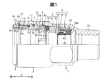
図1は第1実施形態としての管継手を示す部分断面側面図であり、図2は管継手を示す分解斜視図であり、図3は管継手をフレキシブル管とともに示す分解部分断面側面図である。これら図に示すように、第1実施形態としての管継手1は、一端側からフレキシブル管が挿入される内孔21を有し、他端側におねじ部22が形成された継手本体2と、継手本体2に部分的に挿入される押ナット3と、継手本体2の内部に装着される弾性機構部4と、第1のシール部材5と、リテーナ6と、ストップリング7と、第2のシール部材8と、第3のシール部材9と、インジケータリング10とを有する。フレキシブル管は、例えば樹脂被覆した金属コルゲート管である。
A-1. Construction:
1 is a partially sectional side view showing a pipe joint as a first embodiment, FIG. 2 is an exploded perspective view showing a pipe joint, and FIG. 3 is an exploded partial sectional side view showing the pipe joint together with a flexible pipe. . As shown in these drawings, the pipe joint 1 as the first embodiment includes a
(a)継手本体:
図3に示すように、継手本体2の内孔21は、おねじ部22側から順に、おねじ部22の内径より大きな内径を有し、弾性機構部4および第1のシール部材5をスライドして受承する第1の内径部21aと、第1の内径部21aの内径より大きな内径を有し、リテーナ6および押ナット3をスライドして受承する第2の内径部21bとからなり、第1の内径部21aの奥側端部には内方環状突起部23が設けられており、第2の内径部21bの入口側端部には環状溝24が設けられている。第2の内径部21bには、ストップリング7が軸線方向に移動可能に装着される係止溝集合体17が設けられている。係止溝集合体17は、第1〜第3の係止溝171、172、173からなっている。
(A) Fitting body:
As shown in FIG. 3, the
(b)押ナット:
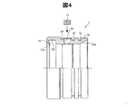
図4は、管継手1が有する押ナット3を示す部分断面側面図である。押ナット3は、リテーナ6に当接するテーパ面31aを有する先端部31と、ストップリング7が進入する第1の外周環状溝32と、円環状の第2のシール部材8を受承する第2の外周環状溝33と、継手本体2の入口端に近接する位置でインジケータリング10を受承する第3の外周環状溝34と、円環状の第3のシール部材9を受承する内周環状溝35と、継手本体2の入口端付近に設けられた外気との連通孔(例えば円孔)36と、内周環状溝35を覆う入口端の内方フランジ部37とを有する。内方フランジ部37の内端部は、内側(内周環状溝35側)に屈曲したカエリ部37aになっている。また連通孔36に選択透過性部材12が装着される。
(B) Push nut:
FIG. 4 is a partial cross-sectional side view showing the
(c)弾性機構部:
図1に示すように、継手本体2と押ナット3との間に装着される弾性機構部4は、フレキシブル管100の装着前には圧縮コイルばね41が圧縮状態に保持されているが、フレキシブル管100を継手本体2の所定位置まで挿入したときに、圧縮コイルばね41の圧縮状態が解放されて伸張することによって、第1のシール部材5をフレキシブル管100の挿入方向(図中のX方向の正の向き)と逆の方向(図中のX方向の負の向き)に押圧し、もってリテーナ6を押ナット3の先端テーパ面31aに当接させる。フレキシブル管100の挿入される前記所定位置は、本実施形態では、フレキシブル管100を挿入したときに後述するフランジ部432が奥に突き当たる位置であり、圧縮コイルばね41が圧縮状態から伸張状態に切り替わる位置である。図1〜図3に示すように、弾性機構部4は、圧縮コイルばね41(図1は圧縮された状態を示す)と、ほぼL字形断面を有するほぼ円筒状のガイド部材42と、ガイド部材42の内側に軸線方向(X方向と一致)に移動可能に設けられるほぼ円筒状の移動部材43とからなる。
(C) Elastic mechanism part:
As shown in FIG. 1, the
図3に示すように、ガイド部材42は、弾性金属板により形成され、中空円板状支持部421と、中空円板状支持部421の円周方向に沿った位置から軸線方向にかつ僅かに内方に傾斜して延出する複数の円弧板部422とを有する。
As shown in FIG. 3, the
図5は、ガイド部材42の拡大断面図である。図5に示すように、円弧板部422は、先端に斜め外方に折曲げられた部分(折曲部)422aを有し、折曲部422aの外面には微少な突起423が設けられている。図3に示すように、移動部材43は、円筒部431と、円筒部431の端部に設けられた肉厚のフランジ部432とを有する。フランジ部432の外周面には、円弧板部422の折曲部422aの外面に設けられた微少な突起423が嵌まる環状凹部432aが設けられている。移動部材43は、スライドを円滑に行うためにエンジニアリングプラスチックのように低比重、高強度および低摩擦係数の材料からなるのが好ましい。
FIG. 5 is an enlarged cross-sectional view of the
図1に示すように、フレキシブル管100を継手本体2に挿入する前の状態では、圧縮コイルばね41はガイド部材42の中空円板状支持部421(図3)と継手本体2の内方環状突起部23との間に圧縮された状態で挟持され、ガイド部材42の円弧板部422の先端折曲部422aは内方環状突起部23に係合している。これにより、フレキシブル管100の装着前には、ガイド部材42は継手本体内に係合している。ガイド部材42の内側に移動部材43が配置され、ガイド部材42の円弧板部422(図3)は継手本体2の内方環状突起部23と移動部材43のフランジ部432とにより挟持される。内方環状突起部23とフランジ部432とによるガイド部材42の円弧板部422の挟持力が圧縮コイルばね41の弾性力より大きくなるように、内方環状突起部23の内径、フランジ部432の外径および円弧板部422の厚さを決める。
As shown in FIG. 1, before the
(d)第1のシール部材:
図1〜図3に示すように、金属コルゲート管101の先端部をシールする第1のシール部材5は、気密パッキン51と、気密パッキン51から延びる複数(本実施形態では4本)の係止爪部52と、気密パッキン51に連結される耐火パッキン53とからなる。気密パッキン51は、継手本体2の第1の内径部21aに密着するように第1の内径部21aの内径よりやや大きい外径を有するとともに、金属コルゲート管101の外径(山部の外径)よりやや小さい内径を有する。気密パッキン51は、また金属コルゲート管101の山部と谷部の繰り返しの数ピッチ分(例えば2ピッチ分)をシールする長さを有し、金属コルゲート管101の外周側を気密にシールすることができる。気密パッキン51は、長期間にわたってシール性能を保持する必要があるので、耐ガス透過性に優れたニトリルブタジエンゴム(NBR)等で形成されている。
(D) First sealing member:
As shown in FIGS. 1 to 3, the
図6は、気密パッキン51と係止爪部52を示す説明図である。図中の(a)は気密パッキン51と係止爪部52の一部分の断面図であり、(b)は気密パッキン51のX方向の負の向き側を示す斜視図であり、(c)は気密パッキン51のX方向の正の向き側を示す斜視図である。図6(a)、(b)に示すように、気密パッキン51の内径側(金属コルゲート管101側)のシール面における、X方向の負の向き側の端部51aには、スリット(溝)51bが形成されている。スリット51bはX方向に延び、X方向の幅は金属コルゲート管101の山部の幅とほぼ同じである。このスリット51bは、ガス漏れ検査時にガス漏れがあるときに必ずガスが検知されるようにするためのものであり、詳細な働きについては後述する。
FIG. 6 is an explanatory view showing the
図6(a)、(c)に示すように、各係止爪部52は、気密パッキン51のX方向の正の向き側の端部51cから、気密パッキン51の内径側の面51dと面一となってX方向の正の向き側に延びる片状の部材であり、その先端部には外側(ガイド部材42側であり、図6(a)の上側)に突出する爪52aを備える。係止爪部52の材料は、気密パッキン51と同一の材料である。図6(a)に示すように、係止爪部52の前記外側の面は、弾性機構部4に備えられるガイド部材42の円弧板部422に接しており、爪52aが、円弧板部422の所定部位に係合される。中空円板状支持部421は、図3および図5に示すように、完全なる円盤状ではなく、円盤状のフランジ部421aと、軸方向に延びる円筒部421bを有する。この円筒部421bのX方向の正の向き側の端部421bEにおいて円弧板部422が延設されていない部分(前記所定部位に相当)に爪52aが係わり合う。この構成によって、気密パッキン51とガイド部材42との間が係合されることになり、図1に示すように、ガイド部材42が継手本体2の内方環状突起部23と移動部材43のフランジ部432とにより挟持されているときには、気密パッキン51はガイド部材42を介して継手本体につながった状態となる。こうした構成の第1のシール部材5が、[発明の概要]の欄に記載された管継手の備える「シール部材」に相当する。
As shown in FIGS. 6 (a) and 6 (c), each locking
図1〜図3に示すように、耐火パッキン53は、気密パッキン51の外径側(継手本体2側)のシール面における、X方向の負の向き側の端部に連結されている。管継手1が火災等で高温に曝されてゴム製の気密パッキン51が焼失しても、耐火パッキン53は熱膨張して継手本体2と金属コルゲート管101との隙間を充たすので、ガス漏れを防止する。また気密パッキン51が焼失すると、弾性機構部4の圧縮コイルばね41が伸長してガイド部材42をX方向の負の向きに移動するので、熱膨張した耐火パッキン53は移動が制限されて、継手本体2の内面と金属コルゲート管101の外周面とをシールする。
As shown in FIGS. 1 to 3, the
耐火パッキン53は、例えば、天然ゴム(NR)、ニトリルブタジエンゴム(NBR)、クロロプレンゴム(CR)、エチレン−プロピレンゴム(EPR)、エチレン−プロピレン−ジエンゴム(EPDM)、シリコーンゴム(SR)等のゴムと、無発泡状態で熱膨張する黒鉛層間化合物と、加硫剤と、必要に応じて充填材、軟化材等の混練物を加硫することにより製造される。黒鉛層間化合物は例えば黒鉛を硫酸で処理することにより得られる。黒鉛層間化合物は170℃以上に加熱されると無発泡状態で数倍〜数十倍に膨張し、800〜1000℃に加熱すると見掛けの体積は100〜250倍に増加する。なお耐火パッキン53の体積および黒鉛層間化合物の配合量は、耐火パッキン53の膨張量および膨張後のガス透過性を考慮して設定するのが好ましい。またシール性の点から、耐火パッキン53は50〜80のショアーA硬度を有するのが好ましい。
The
(e)リテーナ:
図1および図2に示すように、弾性変形可能な材料(例えばエンジニアリングプラスチック)からなるリテーナ6は、円筒状基部61と、円筒状基部61から円周方向に等間隔で延出する複数のセグメント62と、各セグメント62の先端に設けられた金属(例えば黄銅)製の爪部63とを有する。各セグメント62の外面は押ナット3の先端テーパ面31aに当接するテーパ面62aとなっている。リテーナ6の円筒状基部61およびセグメント62の内径は金属コルゲート管101の山部の外径より大きいので、無負荷状態ではフレキシブル管100を挿入するときには引っ掛からない。しかしセグメント62間にスリットがあるので、後述する圧縮コイルばね41の伸張力によりセグメント62のテーパ面62aが押ナット3の先端テーパ面31aに押圧されると、セグメント62は内方に曲げられる。その結果、セグメント62の先端に設けられた爪部63は金属コルゲート管101の谷部に係合する。こうした構成のリテーナ6が、[発明の概要]の欄に記載された管継手の備える「抜け止め部材」に相当する。
(E) Retainer:
As shown in FIGS. 1 and 2, a
(f)ストップリング:
ストップリング7は弾性変形可能なC字状部材であり、施工作業段階に応じて継手本体2に設けられた第1〜第3の係止溝171、172、173のいずれかに係合し、押ナット3を継手本体2の複数の位置のいずれかに保持する(ロックする)。この機能を有効に発揮するために、ストップリング7はオーステナイト系ステンレス鋼のような弾性金属の線材からなるのが好ましい。
(F) Stop ring:
The
(g)第2のシール部材:
押ナット3の第2の外周環状溝33に受承された第2のシール部材8は継手本体2に密着し、押ナット3と継手本体2とをシールし、外部からの雨水の侵入を防止する。第2のシール部材8は、例えばエチレン−プロピレン−ジエンゴム(EPDM)等のオレフィン系ゴムからなるOリングが好ましい。
(G) Second seal member:
The
(h)第3のシール部材:
図7は、第3のシール部材を示す説明図である。図中の(a)は第3のシール部材を示す断面図であり、(b)は第3のシール部材の一部分を押ナットと共に示す部分拡大断面図である。図7(a)に示すように、押ナット3の内周環状溝35に受承される第3のシール部材9は、ほぼL字状の断面を有し、内周環状溝35に嵌入する環状本体部9aと、環状本体部9aから延びる内方リップ9bとを有するリップパッキンである。リップパッキンは、例えばEPDM等のオレフィン系ゴムからなるのが好ましい。
(H) Third seal member:
FIG. 7 is an explanatory view showing a third seal member. (A) in a figure is sectional drawing which shows a 3rd seal member, (b) is a partial expanded sectional view which shows a part of 3rd seal member with a push nut. As shown in FIG. 7A, the
環状本体部9aは内方リップ9bより外側(内方フランジ部37側)に延びた段部9cを有する。図7(b)に示すように、第3のシール部材9の段部9cは、内方フランジ部37のカエリ部37aに係止される。押ナット3にフレキシブル管100を挿入すると、内方リップ9bは奥側に弾性的に屈曲し、所望のシール面圧でフレキシブル管100を押圧する。その結果、押ナット3とフレキシブル管100とはシールされ、外部から雨水が侵入するのが防止される。フレキシブル管100の挿入により第3のシール部材9に奥側方向の応力がかかるが、第3のシール部材9の段部9cとカエリ部37aとの係合により第3のシール部材9が内周環状溝35から脱離することはない。
The annular
(i)インジケータリング:
図1および図2に示すように、フレキシブル管100の管継手1への接続完了を確認するとともに、フレキシブル管100が挿入された管継手1の分解作業を容易にするために、インジケータリング10が押ナット3の第3の外周環状溝34に着脱自在に装着されている。インジケータリング10は金属製のC字状リングであり、無負荷状態では第3の外周環状溝34の外径より小さい内径を有する。押ナット3を継手本体2に挿入した状態では、インジケータリング10は継手本体2の入口端の環状溝24に覆われており、外から見えない。しかし、フレキシブル管100の管継手1への接続完了を確認するためにフレキシブル管100を引っ張ると、後述するようにストップリング7が第2の係止溝172に入るとともに、インジケータリング10は継手本体2の環状溝24から露出する。フレキシブル管100の管継手1への完全な接合を目視で確認できるように、インジケータリング10を継手本体2および押ナット3と異なる色にするのが好ましい。
(I) Indicator ring:
As shown in FIGS. 1 and 2, in order to confirm the completion of connection of the
(j)選択透過性部材:
配管施工時に金属コルゲート管101に誤って釘が打ち込まれたとき等に起こるガス漏れを検出するために、押ナット3の連通孔36に選択透過性部材12が設けられている。漏出したガスは金属コルゲート管101と樹脂被覆102との間隙に入るので、選択透過性部材12を通って外部に導き、ガスセンサ等により検知することができる。選択透過性部材12は、ガス透過性を有するが配管施工後長期間水分、塵芥等の侵入を防止し得る多孔質部材である。このような多孔質部材は、ポリオレフィン(ポリエチレン、ポリプロピレン等)、ポリメチルメタクリレート、ポリスチレン、エチレン酢酸ビニル共重合体、ポリテトラフルオロエチレン等のポリマーの多孔質体であるのが好ましい。
(J) Selective permeability member:
The
(k)係止機構:
図8は、管継手1の組立時における係止機構11の変化を示す説明図である。図中の(a)は押ナット3を継手本体2に挿入し始めたときのストップリング7と係止溝との位置関係を示す断面図であり、(b)は押ナット3を継手本体2に挿入する途中におけるストップリング7と係止溝との位置関係を示す断面図であり、(c)は押ナット3をリテーナ6に当接するまで継手本体に挿入したときのストップリング7と係止溝との位置関係を示す断面図である。係止機構11は、継手本体2の内面に設けられた相互に連通する第1〜第3の係止溝171、172、173からなる係止溝集合体17と、押ナット3に設けられた第1の外周環状溝32とからなる。第1の係止溝171は、環状溝部171aと、環状溝部171aの内面からX方向の負の向きに向って縮径するテーパ面を有するテーパ状溝部171bとからなる。第1の係止溝171のテーパ状溝部171bと連通する第2の係止溝172は、X方向の負の向きに向って拡径するテーパ面を有するテーパ状溝部172bと、テーパ状溝部172bに連なる内面を有する環状溝部172aとからなる。第1の係止溝171のテーパ状溝部171bと第2の係止溝172のテーパ状溝部172bとにより山形の内方環状突部174が形成される。第3の係止溝173は第1の係止溝171の環状溝部171aに連通する。
(K) Locking mechanism:
FIG. 8 is an explanatory view showing a change of the
第1および第2の係止溝171、172は山形の内方環状突部174を介して連通しているので、ストップリング7を内方環状突部174の内径より小さく縮径する力を押ナット3に加えると、ストップリング7を第1の係止溝171から第2の係止溝172に移動させることができるし、第2の係止溝172から第1の係止溝171に移動させることもできる。しかし、ストップリングの縮径力未満の力であれば、内方環状突部174は、第1の係止溝171に収容されているストップリング7が第2の係止溝172に移動するのを防止する。
Since the first and second locking
本実施形態では、フレキシブル管100の接続工程ではストップリング7が第1の係止溝171に保持されたままであり(図8(c)参照)、フレキシブル管100の接続確認工程で始めてストップリング7が第1の係止溝171から内方環状突部174を越えて第2の係止溝172に移動するように(図8(b)参照)、内方環状突部174の側面の傾斜角(テーパ角)α1を設定する必要がある。換言すれば、弾性機構部4の作用(圧縮コイルばね41の伸張力)ではストップリング7が内方環状突部174を越えないが、接続確認のためにフレキシブル管100を引っ張る力ではストップリング7が内方環状突部174を越えるように、テーパ角α1を比較的大きく設定する必要がある。具体的には、上記接続確認のためにフレキシブル管100を引っ張る作業を平均的な作業者が行った場合に良好な手応え感(クリック感)が得られるように、テーパ角α1を設定するのが好ましい。また、継手本体2に押ナット3を組み立てるときに、ストップリング7が第2の係止溝172から第1の係止溝171に内方環状突部174を越えて移動できるように内方環状突部174のもう一方の側面の傾斜角(テーパ各)α2を設定する必要がある。このテーパ角α1、α2は例えば40〜50°である。勿論、圧縮コイルばね41の伸張力に応じてテーパ角α1、α2は適宜変更可能である。
In the present embodiment, the
なお、本実施形態では、(i)第1の係止溝171と第2の係止溝172の合計長さとストップリング7の直径Dとの関係、(ii)第1の係止溝171の深さや長さとストップリング7の直径Dとの関係、(iii)第2の係止溝172の深さや長さとストップリング7の直径Dとの関係、(iv)第3の係止溝173の深さや長さとストップリング7の直径Dとの関係等についても適正に設定することで、ストップリング7の各係止溝171〜173間の移動をスムーズに行うことができるが、これらの適正な関係は、特許文献1(国際公開WO/2010/131609号公報)に記載された通りとすることができる。
In this embodiment, (i) the relationship between the total length of the
A−2.接続作業:
(a)管継手の組立;
配管現場で直ぐに使用できるような形態に管継手1を組み立てるために、まず治具を用いて圧縮コイルばね41、ガイド部材42および移動部材43を図1に示すように継手本体2内にセットし、次いで気密パッキン51および耐火パッキン53からなる第1のシール部材5、およびリテーナ6を継手本体2内に挿入し、最後に第2のシール部材8、第3のシール部材9およびインジケータリング10を装着した押ナット3を継手本体2内に挿入する。このとき、図8(a)に示すようにストップリング7をまず押ナット3の第1の外周環状溝32に入れる。第1の外周環状溝32はストップリング7の直径Dより深いので、ストップリング7は第1の外周環状溝32に完全に収容され、押ナット3は継手本体2内を抵抗なくスライドできる。押ナット3の進入途中で第1の外周環状溝32は第2の係止溝172と整合し、ストップリング7は図8(b)に示すように第2の係止溝172内に進入するが、さらに押ナット3をスライドさせるとストップリング7は山形の内方環状突部174を越えて図8(c)に示すように第1の係止溝171に進入する。第1の係止溝171の深さはストップリング7の直径Dより小さいので、ストップリング7は第1の係止溝171と第1の外周環状溝32とに跨がる。このようにして管継手1は組み立てられる。
A-2. Connection work:
(A) Assembling pipe fittings;
In order to assemble the pipe joint 1 in such a form that it can be used immediately at the piping site, first, the
(b)フレキシブル管の挿入動作:
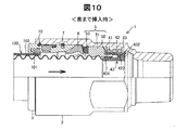
図9は管継手にフレキシブル管を挿入する途中を示す部分断面側面図であり、図10は奥に突き当たるまでフレキシブル管を挿入したときの管継手の部分断面側面図であり、図11はガイド部材が解放されたときの部分断面側面図である。数山分の長さの樹脂被覆102を先端部から除去したフレキシブル管100を管継手1に挿入すると、図9の状態を経た後、図10に示すように、金属コルゲート管101の先端は移動部材43の円筒部431に当接する。ここで、さらにフレキシブル管100を継手本体2内に押し込むと、図11に示すように移動部材43のフランジ部432は継手本体2の内方環状突起部23からずれ、ガイド部材42の円弧板部422は内方環状突起部23と移動部材43のフランジ部432との挟持から開放される。
(B) Flexible tube insertion operation:
FIG. 9 is a partial cross-sectional side view showing the way of inserting the flexible pipe into the pipe joint, FIG. 10 is a partial cross-sectional side view of the pipe joint when the flexible pipe is inserted until it hits the back, and FIG. It is a partial cross section side view when is released. When the
そのため、図11に示すように圧縮コイルばね41の伸張力により、ガイド部材42の中空円板状支持部421はX方向の負の向きにスライドして第1のシール部材5の気密パッキン51を押す。第1のシール部材5に押されたリテーナ6はX方向の負の向きにスライドし、押ナット3の先端テーパ面31aに押し付けられる。リテーナ6のセグメント62のテーパ面62aが押ナット3のテーパ面31aと当接すると、セグメント62は内側に変形し、セグメント62のテーパ面62aが押ナット3のテーパ面31aに密着するとともに、セグメント62の爪部63が金属コルゲート管101の谷部に係合する。その結果、フレキシブル管100は管継手1から脱着しなくなる。フレキシブル管100のこの挿入動作の際、圧縮コイルばね41が瞬時に延びてガイド部材42を押すので、カチッというクリック音がする。このクリック音により、フレキシブル管100が管継手1に正常に接合されたことを確認できる。
Therefore, as shown in FIG. 11, the hollow disk-
圧縮コイルばね41が開放されると、その伸張力による軸線方向の圧縮により気密パッキン51は半径方向に膨張するので、継手本体2とフレキシブル管100とのシール性が向上する。したがって、金属コルゲート管101に多少の変形(例えば扁平化又は曲がり)があってもフレキシブル管100を継手本体2に気密に接合することができる。またシール部材8により継手本体2と押ナット3とのシール性が確保され、フレキシブル管100の外周面に密着するシール部材9によりフレキシブル管100と押ナット3とのシール性が確保され、外部からの雨水の侵入を防止する。
When the
(c)フレキシブル管の接続確認:
図11に示す状態でフレキシブル管100は管継手1に正常に接合されているが、それを確認するとともに、施工管理者が後で確認できるようにするために、フレキシブル管100を管継手1から引っ張る。フレキシブル管100は気密パッキン51およびリテーナ6の爪部63により押ナット3に強固に連結しているので、押ナット3はフレキシブル管100と一体となって継手本体2から僅かにX方向の負の向きに移動し、図12に示すようにインジケータリング10が継手本体2の環状溝24から現れる。
(C) Connection confirmation of flexible pipe:
In the state shown in FIG. 11, the
このとき、図13に示すように、ストップリング7は第1の係止溝171から内方環状突部174を越えて第2の係止溝172に移動し、第2の係止溝172と第1の外周環状溝32とに跨がる位置に保持される。この位置からさらに押ナット3を引き抜こうとしても、第1の外周環状溝32に押されるストップリング7が第2の係止溝172の入口側の垂直な内壁に当るので、押ナット3がスライドすることはない。一方、押ナット3を継手本体2内に押し込もうとしても、圧縮コイルばね41の弾発力により容易にはスライドしない。このように押ナット3と継手本体2との相対移動が阻止されるので、フレキシブル管100に引き抜き力が作用しても、フレキシブル管100が管継手1から抜けることはなく、フレキシブル管100を挿入する(管継手1と接続する)施工が正常に完了したことを確認できる。
At this time, as shown in FIG. 13, the
図12に示すように、継手本体2の端部から現れたインジケータリング10により、施工現場が狭くまた暗所であっても施工管理者は触診によりフレキシブル管の接続完了を確認できる。またインジケータリング10の少なくとも外周面を継手本体2および押ナット3と異なる色に着色しておくと、目視でもフレキシブル管の接続完了を確認できる。このようにフレキシブル管100の押し込み後にフレキシブル管100を引っ張る工程を追加することにより、フレキシブル管100の管継手1への接続完了を確実に確認できるだけでなく、接続作業が正常に行われたかどうかの不安感を完全に払拭することができる。
As shown in FIG. 12, the construction manager can confirm the completion of the connection of the flexible pipe by palpation even when the construction site is narrow or dark, with the
なお、本実施形態の管継手1では、押ナット3からインジケータリング10を取り外し、押ナット3を継手本体2内に押し込むことによって、管継手1を分解することができるが、この分解作業については、本発明の要旨とは関係ないので、説明を省略する。
In the pipe joint 1 of the present embodiment, the pipe joint 1 can be disassembled by removing the
A−3.作用、効果:
以上のように構成された第1実施形態の管継手1によれば、ガイド部材42が継手本体2の内方環状突起部23と移動部材43のフランジ部432とにより挟持されている(以下、「ロックされている」と呼ぶ)とき、すなわち、圧縮コイルばね41が圧縮状態にあるときには、気密パッキン51はガイド部材42と係合することによって継手本体2につながった状態となることから、ガイド部材42がロックされているときに、気密パッキン51はフレキシブル管100の挿入方向とは逆方向(図1におけるX方向の負の向き)へスライドすることがない。
A-3. Action, effect:
According to the pipe joint 1 of the first embodiment configured as described above, the
これに対して、比較例の管継手によれば、ガイド部材がロックされているときに、気密パッキンがフレキシブル管の挿入方向とは逆方向へスライドする虞があるが、この点について図面を用いて、次に説明する。 In contrast, according to the pipe joint of the comparative example, when the guide member is locked, the hermetic packing may slide in the direction opposite to the insertion direction of the flexible pipe. This will be described next.
図14は、比較例の管継手についての課題を示す説明図である。比較例の管継手は、図示するもので、特許文献1(国際公開WO/2010/131609号公報)に記載された管継手とほぼ同じ構成を有している。この比較例の管継手901では、気密パッキン951と弾性機構部904との間が分離した構成となっている。すなわち、第1実施形態の管継手1では、気密パッキン51には係止爪部52が付設されており、弾性機構部4の有するガイド部材42と気密パッキン51との間が係止爪部52によって係合するように構成されているのに対して、比較例の管継手901では、係止爪部52に相当する構成を有しない。
FIG. 14 is an explanatory diagram showing a problem with the pipe joint of the comparative example. The pipe joint of the comparative example is shown in the figure and has substantially the same configuration as the pipe joint described in Patent Document 1 (International Publication WO / 2010/131609). In the
比較例の管継手901では、フレキシブル管100が奥に突き当たるまで挿入されていない状態において、接続確認のためにフレキシブル管を矢印Yの方向に引っ張る際に、誤った引っ張り方をした場合に、図14(a)に示すように、そのフレキシブル管100の引っ張り動作に伴って気密パッキン951がフレキシブル管100の挿入方向とは逆方向(図中のX方向の負の向き)へスライドすることが考えられる。誤った引っ張り方としては、例えばフレキシブル管を極端に斜めの方向に引っ張ることがあげられる。
In the
図14(b)に示すように、気密パッキン951が管挿入方向とは逆方向へスライドしたことで、リテーナ906が縮径されてフレキシブル管100と係合する。このとき、押しナット903が軸移動してインジケータリング10が露出する。このため、作業者は、フレキシブル管100を奥に突き当たるまで挿入していないような不完全な施工状態であっても、接続確認工程で正常な施工が行われたと判断してしまうことになる。図14(b)の状態では、リテーナ906が縮径されてフレキシブル管100はロックされているが、圧縮コイルばね41は解放されていない状態であることから、リテーナ906は気密パッキン951を介した圧縮コイルばね41による押圧力を受けていない。このために、フレキシブル管100のロックは強固でなく、その後の振動等でロックが外れる虞がある。
As shown in FIG. 14B, the
これに対して、第1実施形態の管継手1によれば、前記(I)、(II)の条件下でも、ガイド部材42が継手本体2に係合されている限り、気密パッキン51はフレキシブル管100の挿入方向とは逆方向(図1におけるX方向の負の向き)へスライドすることがない。したがって、第1実施形態の管継手1によれば、フレキシブル管100が奥に突き当たるまで挿入されていない状態で接続確認を行った場合にはフレキシブル管100は管継手1から抜け出すので、施工が正常に完了したと誤って判断されることを確実に防止することができる。
On the other hand, according to the pipe joint 1 of the first embodiment, the
なお、比較例の管継手901では、図14(b)の状態では、フレキシブル管100と気密パッキン51が接しているため、この状態でガス漏れ検査を行なったとしても、施工が正常に完了していないことを発見できない虞があった。このため、第1実施形態の管継手1の有効性が高いと言える。
In addition, in the
さらに、第1実施形態の管継手1は、気密パッキン51にスリット51b(図6(a)、(b)参照)が形成されていることから、次の効果を奏する。比較例の管継手901の課題を示した図14(b)において、気密パッキン951に、第1実施形態の気密パッキン51と同一のスリット51bが設けられた場合を考えてみると、スリット51bは破線で示した箇所に位置する。このスリット51bの箇所は、フレキシブル管100の先端の1山部分と対向する位置にあり、気密パッキン951とスリット51bの間のガス漏れの流路となり得る。したがって、第1実施形態の管継手1において、仮に気密パッキン51の係止爪部52の係合が外れた状態で、リテーナ6がフレキシブル管100の先端の1山部分に係合した場合にも、スリット51bがガス漏れの流路となることから、ガス漏れ検査で判定が可能となる。したがって、第1実施形態の管継手1によれば、施工が正常に完了していない状態で、施工が正常に完了されたと判断されることを、より防止することができ、管継手としての信頼性をより向上することができる。
Furthermore, the pipe joint 1 according to the first embodiment has the following effects because the
B.第2実施形態:
図15は、本発明の第2実施形態としての管継手が備える気密パッキン51と係止爪部52Aを示す説明図である。図中の(a)は気密パッキン51と係止爪部52Aの一部分の断面図であり、(b)は気密パッキン51のX方向の正の向き側を示す斜視図である。第2実施形態における管継手は、第1実施形態における管継手1と比べて、気密パッキン51に付設される係止爪部52Aの構成が相違する。第2実施形態における管継手のその他の構成は、第1実施形態における管継手1の構成と同一であるので、同一の構成要素については、図15において、図6と同一の符合を付し、その説明を省略する。
B. Second embodiment:
FIG. 15 is an explanatory view showing an
図15に示すように、各係止爪部52Aは、気密パッキン51のX方向の正の向き側の端部51cから、気密パッキン51の外径側の面51eと面一となってX方向の正の向き側に延びる片状の部材であり、その先端部には内側(15(a)の下側)に突出する爪52aAを備える。係止爪部52Aの材料は、気密パッキン51と同一の材料である。図15(a)に示すように、係止爪部52の爪52aが、ガイド部材42の中空円板状支持部421の外周に係合している。こうした構成によって、第1実施形態と同様に、気密パッキン51とガイド部材42との間が係合される。したがって、第2実施形態の管継手によれば、第1実施形態の管継手1と同様に、フレキシブル管100が奥に突き当たるまで挿入されていない状態で接続確認を行った場合に、施工が正常に完了したと誤って判断されることを防止することができる。
As shown in FIG. 15, each locking
なお、第2実施形態では、係止爪部52Aは、気密パッキン51と同一の材料によって形成される構成としたが、これに換えて金属材料によって形成される構成としてもよい。この場合には、インサート射出成形によって製造することができる。また、同様に、第1実施形態においても、係止爪部52は、金属材料によって形成される構成としてもよい。
In the second embodiment, the locking
C.第3実施形態:
図16は、本発明の第3実施形態としての管継手が備える気密パッキン51とガイド部材の有する円弧板部422との一部分を示す断面図である。第1および第2実施形態では、気密パッキン51とガイド部材42との間を係止爪部52、52Aによって係合するようにしていたが、これらに換えて、第3実施形態では、気密パッキン51とガイド部材42との間を接着剤BDによって接合するようにした。接着剤BDは、例えばニトリルゴム系やシアノアクリレート系の接着剤を用いることができる。こうした構成の第3実施形態の管継手によれば、第1実施形態の管継手1と同様な効果を奏することができる。
C. Third embodiment:
FIG. 16 is a cross-sectional view showing a part of an
D.第4実施形態:
図17は、本発明の第4実施形態としての管継手が備える弾性機構部4Bおよびその周辺を示す説明図である。第4実施形態における管継手は、第1実施形態における管継手1と比べて、弾性機構部4Bの構成と、気密パッキン51とガイド部材42Bの間の係合方法が相違する。第4実施形態における管継手のその他の構成は、第1実施形態における管継手1の構成と同一であるので、同一の構成要素については、図17において、図1と同一の符合を付し、その説明を省略する。なお、気密パッキン51とガイド部材42Bの間の係合方法は、第3実施形態と同様に接着剤によって接合されている。接着剤は図示していない。
D. Fourth embodiment:
FIG. 17 is an explanatory view showing an
第4実施形態における継手本体2Bの有する第1の内径部21aBは、第1実施形態における第1の内径部21aと比較して、内方環状突起部23(図1)を有しない点と、切欠部211Bを有する点が相違する。第1の内径部21aBのその他の構成は第1実施形態と同一である。
The first inner diameter portion 21aB of the
第4実施形態における管継手の有する弾性機構部4Bは、圧縮コイルばね41と、ガイド部材42Bと、移動部材43Bと、スペーサ部材44Bとからなる。圧縮コイルばね41は、第1実施形態と同一である。ガイド部材42Bと移動部材43Bは、第1実施形態と比べて形状が少し相違するが、同一の機能を有する。第1実施形態と大きく相違するのは、弾性機構部4Bにスペーサ部材44Bを有する点である。
The
図18は、スペーサ部材44Bの斜視図である。スペーサ部材44Bは、中空円板状の部材であり、その外周部分には、複数の折れ曲がった係合片441Bが形成されている。図17に示すように、スペーサ部材44Bは、その内周部分がガイド部材42によって支持されており、係合片441Bによって第1の内径部21aBに設けられた切欠部211Bに係合されている。これによって、圧縮コイルばね41は、ガイド部材42Bの中空円板状支持部421Bとスペーサ部材44Bの間に圧縮された状態で挟持される。フレキシブル管が奥に突き当たるまで挿入されると、移動部材43Bのフランジ部432Bが、第3の内径部21cB側に押し込まれることにより、ガイド部材42Bはフランジ部432Bおよびスペーサ部材44Bから離脱する。したがって、圧縮コイルばね41が開放されることになり、その伸張力により第1のシール部材5がフレキシブル管100の挿入方向とは逆の方向(X方向の負の向き)にスライドする。その後の動作は、第1実施形態と同じである。なお、本実施の形態では係合片441Bが係合する切欠部211Bは第1の内径部21aBに形成されているがこれに限定されない。スペーサ部材の外径を適宜設定することで、切欠部は第3の内径部21cBに設けることもできる。
FIG. 18 is a perspective view of the
以上のように構成された第4実施形態の管継手によれば、第1実施形態の管継手1と同様に、フレキシブル管が奥に突き当たるまで挿入されていない状態で接続確認を行った場合に、施工が正常に完了したと誤って判断されることを防止することができる。さらに、第4実施形態の管継手によれば、弾性機構部4Bは各部品が予め一体化された状態で継手本体2Bの内部に装着することができる。したがって、組み立てられた弾性機構部4Bを継手本体2Bに挿入すればよいので管継手の組み立てが容易となる。
According to the pipe joint of the fourth embodiment configured as described above, similarly to the pipe joint 1 of the first embodiment, when the connection is confirmed in a state where the flexible pipe is not inserted until it hits the back. Therefore, it can be prevented that it is erroneously determined that the construction has been normally completed. Furthermore, according to the pipe joint of the fourth embodiment, the
なお、第4実施形態の管継手では、気密パッキン51とガイド部材42Bとの間を第3実施形態と同様に接着剤によって接合する構成としていたが、これに換えて、気密パッキン51とガイド部材42との間を、第1実施形態における係止爪部52もしくは第2実施形態における係止爪部52Aによって係合する構成としてもよい。
In addition, in the pipe joint of 4th Embodiment, it was set as the structure joined between the
E.変形例:
なお、この発明は上記の第1ないし第4実施形態やその変形例に限られるものではなく、その要旨を逸脱しない範囲において種々の態様において実施することが可能であり、例えば次のような変形も可能である。
E. Variations:
The present invention is not limited to the above-described first to fourth embodiments and modifications thereof, and can be implemented in various modes without departing from the gist thereof. For example, the following modifications are possible. Is also possible.
・変形例1:
第1ないし第4実施形態では、フレキシブル管の接続工程とフレキシブル管の接続が正常であることの接続確認工程とを二回のアクションで行う構造を有するものとしたが、これに換えて、一回のアクションで行う構造を有するものとしてもよい。具体的には、第1ないし第4実施形態では、係止機構11を構成する第1の係止溝171と第2の係止溝172との間の内方環状突部174を山形としたが、これに換えて、特許文献1における第二の実施形態に記載されているとおり、内方環状突部を高さの低い断面台形状とする。この構成によって、圧縮コイルばねの解放によりストップリングが第1の係止溝から第2の係止溝に直ちに移動させることができる。したがって、この変形例1の管継手によれば、フレキシブル管の挿入が完了すると、フレキシブル管を引っ張る動作を行うことなしに、インジケータリングが継手本体から現出する。この結果、接続工程と接続確認工程とを一回のアクションで行うことが可能となる。
・ Modification 1:
In the first to fourth embodiments, the flexible pipe connection process and the connection confirmation process for confirming that the flexible pipe connection is normal are performed in two actions. It may have a structure that is performed by a single action. Specifically, in the first to fourth embodiments, the inner
・変形例2:
本発明に係る管継手の形状は一端に雄ねじ部を有する片ねじソケットに限らず、両ソケット、エルボ、ティー、または雌ねじを有するものであってもよい。またガス栓やガスメータなどの機器の端部に本発明の継手構造を一体的に設けることもできる。
The shape of the pipe joint according to the present invention is not limited to a single screw socket having a male thread portion at one end, but may have both sockets, elbows, tees, or female threads. Further, the joint structure of the present invention can be integrally provided at the end of a device such as a gas stopper or a gas meter.
なお、前述した実施形態および各変形例における構成要素の中の、独立請求項で記載された要素以外の要素は、付加的な要素であり、適宜省略可能である。 It should be noted that elements other than those described in the independent claims among the constituent elements in the above-described embodiment and each modification are additional elements and can be omitted as appropriate.
1…管継手
2、2B…継手本体
3…押ナット
4、4B…弾性機構部
5…第1のシール部材
6…リテーナ
7…ストップリング
8…第2のシール部材
9…第3のシール部材
9a…環状本体部
9b…内方リップ
9c…段部
10…インジケータリング
11…係止機構
12…選択透過性部材
17…係止溝集合体
21…内孔
21a、21aB…第1の内径部
21b…第2の内径部
21cB…第3の内径部
22…ねじ部
23…内方環状突起部
24…環状溝
31…先端部
31a…テーパ面
32〜34…外周環状溝
35…内周環状溝
36…連通孔
37…内方フランジ部
37a…カエリ部
41…圧縮コイルばね
42、42B…ガイド部材
43、43B…移動部材
44B…スペーサ部材
441B…係合片
51…気密パッキン
51a…端部
51b…スリット
51c…端部
52、52A…係止爪部
52a、52aA…爪
53…耐火パッキン
61…円筒状基部
62…セグメント
62a…テーパ面
63…爪部
100…フレキシブル管
101…金属コルゲート管
102…樹脂被覆
171…第1の係止溝
171a…環状溝部
171b…テーパ状溝部
172…第2の係止溝
172a…環状溝部
172b…テーパ状溝部
173…第3の係止溝
174…内方環状突部
211B…切欠部
421、421B…中空円板状支持部
421a…フランジ部
421b…円筒部
422…円弧板部
422a…折曲部
423…突起
431…円筒部
432、432B…フランジ部
432a…環状凹部
DESCRIPTION OF SYMBOLS 1 ...
Claims (7)
一端からフレキシブル管が挿入される内孔を有した継手本体と、
前記内孔において、前記フレキシブル管と前記継手本体とをシールするシール部材と、
前記内孔に設けられるとともに圧縮状態に保持された弾性機構部であって、前記フレキシブル管が所定位置まで挿入されたときに、前記圧縮状態が解放されて伸張することによって、前記フレキシブル管の挿入方向とは逆方向へ前記シール部材をスライドさせる弾性機構部と、
前記シール部材に隣接し、前記シール部材のスライドによる押圧力を受けることによって、前記フレキシブル管と係合して前記フレキシブル管を抜け止めする抜け止め部材と、
を備え、
前記シール部材は、前記弾性機構部が圧縮状態にあるときに、前記弾性機構部にかかわり合って前記継手本体につながった状態となり、
前記弾性機構部は、圧縮ばねと、一端に前記圧縮ばねを支持するための支持部を備えるガイド部材と、該ガイド部材の内側に接し前記フレキシブル管の挿入を受けて軸方向に移動可能に設けられる移動部材と、を備え、
前記移動部材が前記ガイド部材と非接触になる位置に移動することに伴って、前記圧縮ばねが伸長し、前記シール部材が前記フレキシブル管の挿入方向とは逆方向へスライドするように構成し、
前記シール部材は、前記弾性機構部のガイド部材に対して係合部によって係合された、管継手。 A pipe joint,
A joint body having an inner hole into which the flexible pipe is inserted from one end;
In the inner hole, a sealing member that seals the flexible pipe and the joint body;
An elastic mechanism provided in the inner hole and held in a compressed state, and when the flexible tube is inserted to a predetermined position, the compressed state is released and expanded to thereby insert the flexible tube. An elastic mechanism that slides the seal member in a direction opposite to the direction;
A retaining member that is adjacent to the seal member and receives the pressing force caused by the sliding of the seal member to engage the flexible tube and prevent the flexible tube from being detached.
With
The sealing member, when the elastic mechanism is in the compressed state, Ri Do a state that led to the joint body Kakawaria' the elastic mechanism,
The elastic mechanism portion is provided with a compression spring, a guide member having a support portion for supporting the compression spring at one end, and an inner side of the guide member so as to be movable in the axial direction upon receiving the insertion of the flexible tube. A moving member,
As the moving member moves to a position where it does not contact the guide member, the compression spring extends, and the seal member is configured to slide in a direction opposite to the insertion direction of the flexible tube,
The seal member is a pipe joint engaged with a guide member of the elastic mechanism portion by an engaging portion .
前記抜け止め部材を前記フレキシブル管に係合させる前記シール部材のスライドが発生したときに、前記スライドに連動して移動することにより前記継手本体から露出するインジケータを備える管継手。 The pipe joint according to claim 1,
A pipe joint comprising an indicator that is exposed from the joint body by moving in conjunction with the slide when a slide of the seal member that engages the flexible pipe with the retaining member occurs.
前記シール部材は、前記弾性機構部のガイド部材に対して接着剤によって接合された、管継手。 The pipe joint according to claim 1 or 2 ,
The said sealing member is a pipe joint joined by the adhesive agent with respect to the guide member of the said elastic mechanism part.
前記弾性機構部は、前記ガイド部材における前記支持部とは反対側の端部に係止されるスペーサ部材を備え、前記支持部と前記スペーサ部材との間に予め前記圧縮ばねを圧縮して挟持した状態で継手本体に装着される、管継手。 A pipe joint according to any one of claims 1 to 3,
The elastic mechanism portion includes a spacer member that is locked to an end portion of the guide member that is opposite to the support portion, and the compression spring is compressed and sandwiched between the support portion and the spacer member in advance. Pipe fittings that are attached to the fitting body in a finished state.
前記継手本体に部分的に挿入されるとともに、前記フレキシブル管が挿入される押ナットと、
前記継手本体に対して前記押ナットを所定の位置に保持する係止機構と、
を備え、
前記係止機構は、
ストップリングと、前記ストップリングを受承するように前記押ナットの外面に形成された環状溝と、前記ストップリングを受承するとともに相互に連通するように前記継手本体の内面に形成された複数の係止溝とからなり、
前記ストップリングは、前記フレキシブル管の接続完了まで前記環状溝と第1の係止溝に跨がって係合しており、
前記フレキシブル管の接続完了後に前記フレキシブル管に抜け方向の力を加えると、前記ストップリングは前記第1の係止溝からそれより入口側の第2の係止溝に移動し、もって前記フレキシブル管の正常な接続を確認できる程度に前記押ナットが前記継手本体から引き出される、管継手。 The pipe joint according to any one of claims 1 to 4 ,
A push nut that is partially inserted into the joint body and into which the flexible pipe is inserted,
A locking mechanism for holding the push nut in a predetermined position with respect to the joint body;
With
The locking mechanism is
A stop ring, an annular groove formed on the outer surface of the push nut to receive the stop ring, and a plurality of grooves formed on the inner surface of the joint body to receive the stop ring and communicate with each other It consists of a locking groove,
The stop ring is engaged across the annular groove and the first locking groove until the connection of the flexible pipe is completed,
When a force in the pulling direction is applied to the flexible pipe after the connection of the flexible pipe is completed, the stop ring moves from the first locking groove to a second locking groove on the inlet side, thereby the flexible pipe. A pipe joint in which the push nut is pulled out from the joint body to such an extent that a normal connection can be confirmed.
前記継手本体に部分的に挿入されるとともに、前記フレキシブル管が挿入される押ナットと、
前記継手本体に対して前記押ナットを所定の位置に保持する係止機構と、
を備え、
前記係止機構は、
ストップリングと、前記ストップリングを受承するように前記押ナットの外面に形成された環状溝と、前記ストップリングを受承するとともに相互に連通するように前記継手本体の内面に形成された複数の係止溝とからなり、
前記ストップリングは、前記フレキシブル管の接続完了まで前記環状溝と第1の係止溝に跨がって係合しており、
前記フレキシブル管の接続完了後に前記フレキシブル管に抜け方向の力を加えると、前記ストップリングは前記第1の係止溝からそれより入口側の第2の係止溝に移動し、もって前記フレキシブル管の正常な接続を確認できる程度に前記押ナットが前記継手本体から引き出され、
前記押ナットに前記インジケータが設けられており、前記インジケータは前記フレキシブル管の接続完了まで前記継手本体に隠蔽されており、接続完了後に前記フレキシブル管を引っ張ると前記押ナットが前記継手本体から引き出されるとともに前記インジケータが前記継手本体から露出する、管継手。 The pipe joint according to claim 2, wherein
A push nut that is partially inserted into the joint body and into which the flexible pipe is inserted,
A locking mechanism for holding the push nut in a predetermined position with respect to the joint body;
With
The locking mechanism is
A stop ring, an annular groove formed on the outer surface of the push nut to receive the stop ring, and a plurality of grooves formed on the inner surface of the joint body to receive the stop ring and communicate with each other It consists of a locking groove,
The stop ring is engaged across the annular groove and the first locking groove until the connection of the flexible pipe is completed,
When a force in the pulling direction is applied to the flexible pipe after the connection of the flexible pipe is completed, the stop ring moves from the first locking groove to a second locking groove on the inlet side, thereby the flexible pipe. The push nut is pulled out from the joint body to such an extent that normal connection of the
The push nut is provided with the indicator, and the indicator is hidden by the joint body until the connection of the flexible pipe is completed. When the flexible pipe is pulled after the connection is completed, the push nut is pulled out from the joint body. And a pipe joint in which the indicator is exposed from the joint body.
前記シール部材の前記フレキシブル管側のシール面における、前記フレキシブル管の挿入方向とは逆方向側の端部に、スリットを備える、管継手。 The pipe joint according to any one of claims 1 to 6 ,
A pipe joint comprising a slit at an end of the sealing member on the side of the flexible pipe opposite to the insertion direction of the flexible pipe.
Priority Applications (1)
| Application Number | Priority Date | Filing Date | Title |
|---|---|---|---|
| JP2013251397A JP6250377B2 (en) | 2013-12-04 | 2013-12-04 | Pipe fitting |
Applications Claiming Priority (1)
| Application Number | Priority Date | Filing Date | Title |
|---|---|---|---|
| JP2013251397A JP6250377B2 (en) | 2013-12-04 | 2013-12-04 | Pipe fitting |
Publications (3)
| Publication Number | Publication Date |
|---|---|
| JP2015108405A JP2015108405A (en) | 2015-06-11 |
| JP2015108405A5 JP2015108405A5 (en) | 2017-01-05 |
| JP6250377B2 true JP6250377B2 (en) | 2017-12-20 |
Family
ID=53438892
Family Applications (1)
| Application Number | Title | Priority Date | Filing Date |
|---|---|---|---|
| JP2013251397A Active JP6250377B2 (en) | 2013-12-04 | 2013-12-04 | Pipe fitting |
Country Status (1)
| Country | Link |
|---|---|
| JP (1) | JP6250377B2 (en) |
Families Citing this family (3)
| Publication number | Priority date | Publication date | Assignee | Title |
|---|---|---|---|---|
| JP2019143786A (en) * | 2018-02-23 | 2019-08-29 | 株式会社ハーマン | Socket and pipe joint including socket |
| CN108709039B (en) * | 2018-06-27 | 2024-04-05 | 日丰企业(佛山)有限公司 | Connecting pipe fitting |
| JP7173437B2 (en) * | 2018-09-18 | 2022-11-16 | 株式会社オンダ製作所 | pipe joint |
Family Cites Families (8)
| Publication number | Priority date | Publication date | Assignee | Title |
|---|---|---|---|---|
| JP2001132881A (en) * | 1999-11-08 | 2001-05-18 | Hitachi Metals Ltd | Bell-and-spigot |
| JP4375871B2 (en) * | 1999-11-18 | 2009-12-02 | 大阪瓦斯株式会社 | One-touch fitting for flexible tube |
| CA2686084A1 (en) * | 2007-05-30 | 2008-12-11 | Titeflex Corporation | Fitting with bushing for corrugated stainless steel tubing |
| JP5046113B2 (en) * | 2007-09-07 | 2012-10-10 | 日立金属株式会社 | Corgate pipe fittings |
| KR101725169B1 (en) * | 2009-05-11 | 2017-04-10 | 히타치 긴조쿠 가부시키가이샤 | Pipe joint |
| JP5461117B2 (en) * | 2009-09-02 | 2014-04-02 | 日立金属株式会社 | Corrugated fitting |
| JP5461116B2 (en) * | 2009-09-02 | 2014-04-02 | 日立金属株式会社 | Pipe fitting |
| JP2012241744A (en) * | 2011-05-17 | 2012-12-10 | Keiyo Gas Kk | Joint for flexible tube |
-
2013
- 2013-12-04 JP JP2013251397A patent/JP6250377B2/en active Active
Also Published As
| Publication number | Publication date |
|---|---|
| JP2015108405A (en) | 2015-06-11 |
Similar Documents
| Publication | Publication Date | Title |
|---|---|---|
| JP5400145B2 (en) | Pipe fitting | |
| JP5046113B2 (en) | Corgate pipe fittings | |
| JP5461116B2 (en) | Pipe fitting | |
| JP6261310B2 (en) | Pipe fitting | |
| JP6250377B2 (en) | Pipe fitting | |
| JP2007198585A (en) | Easy release joint for resin tube | |
| JP2003176888A (en) | Insertion type tube fitting | |
| JP6220658B2 (en) | Pipe fitting | |
| JP5384882B2 (en) | Corgate fittings | |
| JP5671112B2 (en) | Corrugated pipe insertion fitting | |
| JP4426675B2 (en) | Fitting for piping | |
| JP4633215B2 (en) | Corrugated fitting | |
| JP5219266B2 (en) | Corgate fittings | |
| CN108692120B (en) | Pipe joint | |
| JP3386406B2 (en) | Pipe fittings | |
| JP6215676B2 (en) | Pipe fitting | |
| JP5497818B2 (en) | Corrugated pipe insertion fitting | |
| WO2022071504A1 (en) | Joint and construction method for flexible tube | |
| JP2012112451A (en) | Insert-type pipe joint | |
| JP5207906B2 (en) | Fitting for flexible tube | |
| JP2009127759A (en) | Pipe fitting for flexible pipe | |
| JP4980778B2 (en) | Corrugated pipe insertion fitting | |
| JP5570345B2 (en) | Fitting for flexible tube | |
| JP2021152406A (en) | Joint for flexible pipe | |
| JP2023089881A (en) | Joint for flexible pipe |
Legal Events
| Date | Code | Title | Description |
|---|---|---|---|
| A521 | Request for written amendment filed |
Free format text: JAPANESE INTERMEDIATE CODE: A523 Effective date: 20161118 |
|
| A621 | Written request for application examination |
Free format text: JAPANESE INTERMEDIATE CODE: A621 Effective date: 20161118 |
|
| A977 | Report on retrieval |
Free format text: JAPANESE INTERMEDIATE CODE: A971007 Effective date: 20170828 |
|
| A131 | Notification of reasons for refusal |
Free format text: JAPANESE INTERMEDIATE CODE: A131 Effective date: 20170905 |
|
| A521 | Request for written amendment filed |
Free format text: JAPANESE INTERMEDIATE CODE: A523 Effective date: 20171102 |
|
| TRDD | Decision of grant or rejection written | ||
| A01 | Written decision to grant a patent or to grant a registration (utility model) |
Free format text: JAPANESE INTERMEDIATE CODE: A01 Effective date: 20171114 |
|
| A61 | First payment of annual fees (during grant procedure) |
Free format text: JAPANESE INTERMEDIATE CODE: A61 Effective date: 20171122 |
|
| R150 | Certificate of patent or registration of utility model |
Ref document number: 6250377 Country of ref document: JP Free format text: JAPANESE INTERMEDIATE CODE: R150 |
|
| S531 | Written request for registration of change of domicile |
Free format text: JAPANESE INTERMEDIATE CODE: R313531 |
|
| S533 | Written request for registration of change of name |
Free format text: JAPANESE INTERMEDIATE CODE: R313533 |
|
| R350 | Written notification of registration of transfer |
Free format text: JAPANESE INTERMEDIATE CODE: R350 |