JP6239151B2 - Friction material, method of forming the same, and system including friction material - Google Patents
Friction material, method of forming the same, and system including friction material Download PDFInfo
- Publication number
- JP6239151B2 JP6239151B2 JP2016565372A JP2016565372A JP6239151B2 JP 6239151 B2 JP6239151 B2 JP 6239151B2 JP 2016565372 A JP2016565372 A JP 2016565372A JP 2016565372 A JP2016565372 A JP 2016565372A JP 6239151 B2 JP6239151 B2 JP 6239151B2
- Authority
- JP
- Japan
- Prior art keywords
- friction material
- density
- particles
- surface finish
- portions
- Prior art date
- Legal status (The legal status is an assumption and is not a legal conclusion. Google has not performed a legal analysis and makes no representation as to the accuracy of the status listed.)
- Active
Links
- 239000002783 friction material Substances 0.000 title claims description 48
- 238000000034 method Methods 0.000 title claims description 13
- 239000002245 particle Substances 0.000 claims description 26
- 239000000758 substrate Substances 0.000 claims description 10
- 239000011347 resin Substances 0.000 claims description 6
- 229920005989 resin Polymers 0.000 claims description 6
- 239000000853 adhesive Substances 0.000 claims description 4
- 230000001070 adhesive effect Effects 0.000 claims description 4
- 238000000151 deposition Methods 0.000 claims description 3
- 238000003754 machining Methods 0.000 claims description 2
- 239000010410 layer Substances 0.000 description 10
- 239000000463 material Substances 0.000 description 5
- 239000012790 adhesive layer Substances 0.000 description 4
- VYPSYNLAJGMNEJ-UHFFFAOYSA-N Silicium dioxide Chemical compound O=[Si]=O VYPSYNLAJGMNEJ-UHFFFAOYSA-N 0.000 description 2
- 230000015572 biosynthetic process Effects 0.000 description 2
- 238000001816 cooling Methods 0.000 description 2
- 239000012809 cooling fluid Substances 0.000 description 2
- 239000004744 fabric Substances 0.000 description 2
- 229910001369 Brass Inorganic materials 0.000 description 1
- OKTJSMMVPCPJKN-UHFFFAOYSA-N Carbon Chemical compound [C] OKTJSMMVPCPJKN-UHFFFAOYSA-N 0.000 description 1
- 229920000049 Carbon (fiber) Polymers 0.000 description 1
- 229910000831 Steel Inorganic materials 0.000 description 1
- 238000009825 accumulation Methods 0.000 description 1
- 239000004760 aramid Substances 0.000 description 1
- 229920003235 aromatic polyamide Polymers 0.000 description 1
- 230000005540 biological transmission Effects 0.000 description 1
- 239000010951 brass Substances 0.000 description 1
- 229910052799 carbon Inorganic materials 0.000 description 1
- 239000004917 carbon fiber Substances 0.000 description 1
- 230000009977 dual effect Effects 0.000 description 1
- 239000000835 fiber Substances 0.000 description 1
- 239000011521 glass Substances 0.000 description 1
- 238000004519 manufacturing process Methods 0.000 description 1
- VNWKTOKETHGBQD-UHFFFAOYSA-N methane Chemical compound C VNWKTOKETHGBQD-UHFFFAOYSA-N 0.000 description 1
- 238000012986 modification Methods 0.000 description 1
- 230000004048 modification Effects 0.000 description 1
- 239000000123 paper Substances 0.000 description 1
- 239000000377 silicon dioxide Substances 0.000 description 1
- 239000010959 steel Substances 0.000 description 1
- 239000010409 thin film Substances 0.000 description 1
- 239000010455 vermiculite Substances 0.000 description 1
- 229910052902 vermiculite Inorganic materials 0.000 description 1
- 235000019354 vermiculite Nutrition 0.000 description 1
Images


Classifications
-
- B—PERFORMING OPERATIONS; TRANSPORTING
- B05—SPRAYING OR ATOMISING IN GENERAL; APPLYING FLUENT MATERIALS TO SURFACES, IN GENERAL
- B05D—PROCESSES FOR APPLYING FLUENT MATERIALS TO SURFACES, IN GENERAL
- B05D3/00—Pretreatment of surfaces to which liquids or other fluent materials are to be applied; After-treatment of applied coatings, e.g. intermediate treating of an applied coating preparatory to subsequent applications of liquids or other fluent materials
- B05D3/12—Pretreatment of surfaces to which liquids or other fluent materials are to be applied; After-treatment of applied coatings, e.g. intermediate treating of an applied coating preparatory to subsequent applications of liquids or other fluent materials by mechanical means
-
- F—MECHANICAL ENGINEERING; LIGHTING; HEATING; WEAPONS; BLASTING
- F16—ENGINEERING ELEMENTS AND UNITS; GENERAL MEASURES FOR PRODUCING AND MAINTAINING EFFECTIVE FUNCTIONING OF MACHINES OR INSTALLATIONS; THERMAL INSULATION IN GENERAL
- F16D—COUPLINGS FOR TRANSMITTING ROTATION; CLUTCHES; BRAKES
- F16D23/00—Details of mechanically-actuated clutches not specific for one distinct type
- F16D23/02—Arrangements for synchronisation, also for power-operated clutches
- F16D23/025—Synchro rings
-
- F—MECHANICAL ENGINEERING; LIGHTING; HEATING; WEAPONS; BLASTING
- F16—ENGINEERING ELEMENTS AND UNITS; GENERAL MEASURES FOR PRODUCING AND MAINTAINING EFFECTIVE FUNCTIONING OF MACHINES OR INSTALLATIONS; THERMAL INSULATION IN GENERAL
- F16D—COUPLINGS FOR TRANSMITTING ROTATION; CLUTCHES; BRAKES
- F16D65/00—Parts or details
- F16D65/14—Actuating mechanisms for brakes; Means for initiating operation at a predetermined position
- F16D65/16—Actuating mechanisms for brakes; Means for initiating operation at a predetermined position arranged in or on the brake
- F16D65/18—Actuating mechanisms for brakes; Means for initiating operation at a predetermined position arranged in or on the brake adapted for drawing members together, e.g. for disc brakes
- F16D65/186—Actuating mechanisms for brakes; Means for initiating operation at a predetermined position arranged in or on the brake adapted for drawing members together, e.g. for disc brakes with full-face force-applying member, e.g. annular
-
- F—MECHANICAL ENGINEERING; LIGHTING; HEATING; WEAPONS; BLASTING
- F16—ENGINEERING ELEMENTS AND UNITS; GENERAL MEASURES FOR PRODUCING AND MAINTAINING EFFECTIVE FUNCTIONING OF MACHINES OR INSTALLATIONS; THERMAL INSULATION IN GENERAL
- F16D—COUPLINGS FOR TRANSMITTING ROTATION; CLUTCHES; BRAKES
- F16D69/00—Friction linings; Attachment thereof; Selection of coacting friction substances or surfaces
- F16D2069/004—Profiled friction surfaces, e.g. grooves, dimples
-
- F—MECHANICAL ENGINEERING; LIGHTING; HEATING; WEAPONS; BLASTING
- F16—ENGINEERING ELEMENTS AND UNITS; GENERAL MEASURES FOR PRODUCING AND MAINTAINING EFFECTIVE FUNCTIONING OF MACHINES OR INSTALLATIONS; THERMAL INSULATION IN GENERAL
- F16D—COUPLINGS FOR TRANSMITTING ROTATION; CLUTCHES; BRAKES
- F16D2121/00—Type of actuator operation force
- F16D2121/02—Fluid pressure
- F16D2121/04—Fluid pressure acting on a piston-type actuator, e.g. for liquid pressure
-
- F—MECHANICAL ENGINEERING; LIGHTING; HEATING; WEAPONS; BLASTING
- F16—ENGINEERING ELEMENTS AND UNITS; GENERAL MEASURES FOR PRODUCING AND MAINTAINING EFFECTIVE FUNCTIONING OF MACHINES OR INSTALLATIONS; THERMAL INSULATION IN GENERAL
- F16D—COUPLINGS FOR TRANSMITTING ROTATION; CLUTCHES; BRAKES
- F16D2123/00—Multiple operation forces
-
- F—MECHANICAL ENGINEERING; LIGHTING; HEATING; WEAPONS; BLASTING
- F16—ENGINEERING ELEMENTS AND UNITS; GENERAL MEASURES FOR PRODUCING AND MAINTAINING EFFECTIVE FUNCTIONING OF MACHINES OR INSTALLATIONS; THERMAL INSULATION IN GENERAL
- F16D—COUPLINGS FOR TRANSMITTING ROTATION; CLUTCHES; BRAKES
- F16D2250/00—Manufacturing; Assembly
- F16D2250/0038—Surface treatment
- F16D2250/0046—Coating
-
- F—MECHANICAL ENGINEERING; LIGHTING; HEATING; WEAPONS; BLASTING
- F16—ENGINEERING ELEMENTS AND UNITS; GENERAL MEASURES FOR PRODUCING AND MAINTAINING EFFECTIVE FUNCTIONING OF MACHINES OR INSTALLATIONS; THERMAL INSULATION IN GENERAL
- F16D—COUPLINGS FOR TRANSMITTING ROTATION; CLUTCHES; BRAKES
- F16D2300/00—Special features for couplings or clutches
- F16D2300/10—Surface characteristics; Details related to material surfaces
Description
関連出願
本出願は2014年4月29日に出願された米国仮出願第61/985646号の利益を主張するものであり、上記米国仮出願の全体が参照により本明細書に組み込まれているものとする。
RELATED APPLICATION This application claims the benefit of US Provisional Application No. 61 / 985,646 filed Apr. 29, 2014, which is hereby incorporated by reference in its entirety. And
高トルクの用途に使用される摩擦材料は、高温に耐える必要がある。一例の用途は、一般にマニュアル及びデュアルクラッチ変速機に見られるシンクロナイザーリングとの関連である。シンクロナイザーリングは、複数の歯を有する外側面と、接着剤によって結合された摩擦材料を有する内側面とを含むことが知られている。 Friction materials used in high torque applications need to withstand high temperatures. One example application is in connection with synchronizer rings commonly found in manual and dual clutch transmissions. Synchronizer rings are known to include an outer surface having a plurality of teeth and an inner surface having a friction material joined by an adhesive.
1つの既知のタイプの摩擦材料は、機械加工による(すなわち、切削された)溝を含む。これらの摩擦材料は、全体にわたって一貫した密度及び表面仕上げを含む。第2のタイプの既知の摩擦材料も、プレス加工又は成形された溝と、全体にわたって一貫した表面仕上げとを含む。しかしながら、第1のタイプとは異なり、プレス加工/成形された溝内の材料は、隣接する高くなった材料に対して増大した密度を有する。 One known type of friction material includes machined (ie, cut) grooves. These friction materials include a consistent density and surface finish throughout. The second type of known friction material also includes a stamped or molded groove and a consistent surface finish throughout. However, unlike the first type, the material in the pressed / formed groove has an increased density relative to the adjacent raised material.
本発明の例示的な態様による摩擦材料を形成する方法は、特に、粒子が複数の突出部と隣接する突出部の間の溝とを提供するように複数の粒子を基材に堆積させることを含む。 A method of forming a friction material according to an exemplary aspect of the present invention comprises, in particular, depositing a plurality of particles on a substrate such that the particles provide a plurality of protrusions and a groove between adjacent protrusions. Including.
本発明の例示的な態様による摩擦材料は、特に、複数の粒子によって提供される加工層を含む。加工層は、第1の表面仕上げと第1の密度とを有する第1部分を含む。加工層は更に、第1の表面仕上げとは異なる第2の表面仕上げと第1の密度とは異なる第2の密度とを有する第2部分を含む。 The friction material according to an exemplary aspect of the present invention includes, in particular, a working layer provided by a plurality of particles. The work layer includes a first portion having a first surface finish and a first density. The working layer further includes a second portion having a second surface finish different from the first surface finish and a second density different from the first density.
本開示の例示的な態様によるシステムは、特に、機械部品と、機械部品に接続された摩擦材料とを含む。摩擦材料は、複数の粒子によって提供される加工層を含む。加工層は、第1の表面仕上げと第1の密度とを有する第1部分と、第1の表面仕上げとは異なる第2の表面仕上げと第1の密度とは異なる第2の密度とを有する第2部分とを更に含む。 A system according to exemplary aspects of the present disclosure includes, among other things, a machine part and a friction material connected to the machine part. The friction material includes a working layer provided by a plurality of particles. The processed layer has a first portion having a first surface finish and a first density, a second surface finish different from the first surface finish, and a second density different from the first density. A second portion.
先行する段落、特許請求の範囲、又は以下の説明及び図面の実施形態、実施例及び代替案は、それらの様々な態様又はそれぞれの個々の特徴を含め、別々に又は任意の組み合わせで取り入れることができる。一実施形態に関連して説明した特徴は、このような特徴が不適合でない限り、全ての実施形態に適用可能である。 The preceding paragraphs, claims, or embodiments, examples and alternatives of the following description and drawings may be incorporated separately or in any combination, including their various aspects or respective individual features. it can. Features described in connection with one embodiment are applicable to all embodiments as long as such features are not incompatible.
図面は、以下のように簡単に説明することができる。
図1は例示的な機械部品を示し、例示的な機械部品は図示の実施例ではシンクロナイザーリング10である。シンクロナイザーリング10が示されているが、当然のことながら本開示はシンクロナイザーリングを超えている。本開示は、クラッチ板及びトルクコンバーターを含むが、これらに限定されない、他の高トルクの用途のような他の用途に有用である。
FIG. 1 shows an exemplary mechanical component, which is a
シンクロナイザーリング10は、その半径方向外側面14から延びる歯12を含む。動作中、シンクロナイザーリング10の半径方向内側面16は、大量の熱にさらされる。半径方向内側面16は、接着剤によって半径方向内側面16に結合された摩擦材料18を含む。シンクロナイザーリング10は、例として鋼又は真鍮から作られることができる。
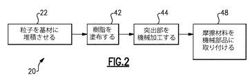
図2は、本開示による摩擦材料18を形成するための例示的な方法20を示す。方法20において、ステップ22で、複数の粒子24(図3)を基材26に堆積させる。粒子24は、炭素、シリカ、ガラス、及びバーミキュライトを含むあらゆる材料から選択されることができる。いくつか例を挙げると、基材26は、炭素繊維織物、紙、繊維、アラミド、又は布材料であることができる。一実施例において、図3に示すように、ホッパー28と、複数の細長い開口32を含むスプレッダー30とを通して、粒子24を基材26に堆積させる。スプレッダー30はすべての実施例で必要ではない。
FIG. 2 illustrates an
ステップ22の結果を図4Aに示す。図4Aにおいて、摩擦材料18は、基材26と、粒子24によって設けられる加工層34とを含む。加工層34は、基材26の反対側に複数の突出部36を含む。突出部36は、スプレッダー30の細長い開口32に起因する粒子の蓄積によってもたらされる。
The result of
ステップ22の後、突出部36には必然的に丸い輪郭38が設けられている。また、突出部36は距離D1だけ離間している。距離D1は、特定の用途に応じて(例えば、シンクロナイザーリング10のサイズに応じて)変えることができる。一実施例において、距離D1は0.1875〜0.5インチ(0.47625〜1.27センチメートル)の範囲にある。ある特定の実施例において、D1は0.375インチ(0.9525センチメートル)である。
After
隣接する突出部36の間の空間は溝40を画定する。溝40において、摩擦材料18は高さD2を有する。高さD2は、一部の実施例では比較的小さいことができる。特に一実施例において、距離D2は溝40の境界が基材26によって提供されるようになっていてもよい。一方、摩擦材料18は、突出部36の丸い輪郭38において高さD3を有する。距離D3は距離D2よりも大きい。
The space between
ステップ22の後、ステップ42で、摩擦材料18に樹脂R(図4Aに模式的に示される)を塗布する。加工層34を構成する粒子24は樹脂Rを吸収する。ステップ42は、適切な飽和のレベルを確実にするために繰り返すことができる。
After
ステップ44で、これまでの丸い輪郭38を本質的に平らにするように突出部36を機械加工(例えば、サンディング)する。平らにされた高さはD4で示される。高さD4は、一実施例においてD3よりも小さく、D2よりも大きい。図4Aは、突出部36の平らな輪郭46を仮想線で示す。図4Bは、平らな輪郭46を見せる機械加工された突出部36を示す。
In
ステップ48で、摩擦材料18を、この実施例ではシンクロナイザーリング10である機械部品に取り付ける。図5に模式的に示される一実施例において、摩擦材料18は、接着層50によってシンクロナイザーリング10の半径方向内側面16に結合されている。適切な結合を確実にするために、摩擦材料18、接着層50、及びシンクロナイザーリング10に熱Hと圧力Pが加えられる。接着層50は、高温の用途に適したあらゆる既知のタイプの接着剤であることができる。接着層50は、摩擦材料18の半径方向内側の加工面53の反対側にある摩擦材料18の外側面51との間に設けられている。
At
ステップ48の結果を図5に示す。図5において、加工層34は、摩擦材料18が全体にわたって実質的に均一な高さD5を有するように圧縮される。高さD5は、一実施例において高さD2以下である。
The result of
圧縮されたとき、加工層34は、第1部分52と第2部分54とを交互に有する。この実施例において、第1部分52は、突出部36が設けられた場所に対応する(突出部36は図5に仮想線で示されている)。一方、第2部分54は、溝40が設けられた場所に対応する(溝40は図5に仮想線で示されている)。
When compressed, the working
ステップ44の機械加工により、第1部分52は、第2部分54の表面仕上げよりも滑らかな第1の表面仕上げを有する。第2部分54はステップ44で機械加工されていないので、第2部分54は(例えば、堆積させた粒子24の未加工の性質により)より粗い、より粒状の表面仕上げが残されている。
Due to the machining of
また、第1部分52はかつて突出部36が存在していた場所に対応するため、第1部分52は第2部分54よりも密になっている。この密度の増加の理由は2つある。第一に、溝40に隣接する場所よりも突出部36を形成するより多くの粒子が存在していた。従って、ステップ42で、より多くの樹脂Rが突出部36によって吸収された。第二に、ステップ44の後も、平らにされた突出部36は溝40に隣接する高さD2よりも大きな高さD4を有していた。従って、ステップ48で圧縮されたとき、第1部分52の粒子は第2部分54の粒子よりも緊密に押し固められる。
Further, since the
異なる第1及び第2部分52、54を提供することによって、摩擦材料18は、加工面53において第1部分52の比較的滑らかな表面により優れた摩耗特性を示す。摩擦材料18はまた、加工面53において第2部分54の粒状の表面仕上げにより優れた摩擦特性を示す。第2部分54の粒状の性質はシンクロナイザーリング10の半径方向内側面16に隣接する冷却流体(例えば、油)の薄い膜を破るのに役立つので、第2部分54の摩擦特性は特に冷間シフトに有益である。
By providing different first and
また、第1部分52が第2部分54よりも高い密度を有するため、冷却流体が第2部分54に向けられ、比較的低密度の第2部分54を通って摩擦材料18に染み渡ることができ、シンクロナイザーリング10と摩擦材料18自体の冷却を向上させる。この冷却の向上は、その結果、シンクロナイザーリングの性能を高め、シンクロナイザーリングと摩擦材料の両方の寿命を延ばす。
Also, because the
図3の実施例において、開口32は互いに平行に延びる直線状の開口である。これにより、摩擦材料18に直線状の平行な複数の第1及び第2部分52、54が設けられる。しかしながら、ジグザグなどの他のパターンも本開示の範囲に該当する。平行な第1及び第2部分52、54が上述されているが、シンクロナイザーリング10の半径方向内側面16は円錐形であることもできるので、第1及び第2部分52、54は半径方向内側面16に取り付けられたときに平行でなくてもよい。
In the embodiment of FIG. 3, the
様々な実施例が図に示される特定の構成要素を有するが、本開示の実施形態はそれらの特定の組み合わせに限定されるものではない。1つの実施例の一部の構成要素又は特徴を別の実施例の特徴又は構成要素と組み合わせて使用することができる。 Although various examples have the specific components shown in the figures, embodiments of the present disclosure are not limited to those specific combinations. Some components or features of one embodiment may be used in combination with features or components of another embodiment.
当業者は上述の実施形態が例示的且つ非限定的であることを理解するであろう。すなわち、本発明の変更例は特許請求の範囲に入る。従って、以下の特許請求の範囲は、その真の範囲及び内容を定めるために検討されるべきである。 One skilled in the art will appreciate that the above-described embodiments are exemplary and non-limiting. That is, modifications of the present invention fall within the scope of the claims. Accordingly, the following claims should be studied to determine their true scope and content.
Claims (19)
粒子が複数の突出部と隣接する突出部の間の溝とを提供するように複数の粒子を基材に堆積させることと、
堆積させた粒子に樹脂を塗布することと
を含む方法。 A method of forming a friction material, comprising:
Depositing a plurality of particles on a substrate such that the particles provide a plurality of protrusions and a groove between adjacent protrusions ;
Applying a resin to the deposited particles .
を更に含む、請求項1に記載の方法。 Further comprising the method of claim 1 in that the protrusions machining said projection to show flat contour.
を更に含む、請求項4に記載の方法。 The method of claim 4 , further comprising compressing the plurality of particles.
機械部品と、
前記機械部品に接続された摩擦材料と
を含み、
前記摩擦材料は、複数の粒子によって設けられた加工層を含み、前記加工層は第1の表面仕上げと第1の密度とを有する第1部分を含み、前記加工層は前記第1の表面仕上げとは異なる第2の表面仕上げと前記第1の密度とは異なる第2の密度とを有する第2部分を更に含む、システム。 System, machine parts,
A friction material connected to the machine part,
The friction material includes a work layer provided by a plurality of particles, the work layer includes a first portion having a first surface finish and a first density, and the work layer includes the first surface finish. And a second portion having a second surface finish that is different from the first density and a second density that is different from the first density.
Applications Claiming Priority (3)
| Application Number | Priority Date | Filing Date | Title |
|---|---|---|---|
| US201461985646P | 2014-04-29 | 2014-04-29 | |
| US61/985,646 | 2014-04-29 | ||
| PCT/US2015/018736 WO2015167663A1 (en) | 2014-04-29 | 2015-03-04 | Friction material and method of forming the same |
Publications (2)
| Publication Number | Publication Date |
|---|---|
| JP2017515071A JP2017515071A (en) | 2017-06-08 |
| JP6239151B2 true JP6239151B2 (en) | 2017-11-29 |
Family
ID=54334355
Family Applications (1)
| Application Number | Title | Priority Date | Filing Date |
|---|---|---|---|
| JP2016565372A Active JP6239151B2 (en) | 2014-04-29 | 2015-03-04 | Friction material, method of forming the same, and system including friction material |
Country Status (6)
| Country | Link |
|---|---|
| US (3) | US9683613B2 (en) |
| EP (1) | EP3137782B1 (en) |
| JP (1) | JP6239151B2 (en) |
| KR (1) | KR101944171B1 (en) |
| CN (1) | CN106255837B (en) |
| WO (1) | WO2015167663A1 (en) |
Families Citing this family (5)
| Publication number | Priority date | Publication date | Assignee | Title |
|---|---|---|---|---|
| US20180209502A1 (en) * | 2015-08-13 | 2018-07-26 | Schaeffler Technologies AG & Co. KG | Chemically activated friction material |
| DE102016224223A1 (en) * | 2016-12-06 | 2018-07-05 | Bayerische Motoren Werke Aktiengesellschaft | Brake pad for a disc brake |
| GB2564436A (en) * | 2017-07-10 | 2019-01-16 | Victrex Mfg Ltd | Polymeric transmission system components |
| KR102039788B1 (en) * | 2017-09-25 | 2019-11-26 | 주식회사 영진정공 | Synchronizer ring friction materials |
| DE112019002464T5 (en) | 2018-05-16 | 2021-01-28 | Tenneco Inc. | BRAKE PAD BACKING PLATE |
Family Cites Families (20)
| Publication number | Priority date | Publication date | Assignee | Title |
|---|---|---|---|---|
| US2242877A (en) * | 1939-03-15 | 1941-05-20 | Albertson & Co Inc | Abrasive disk and method of making the same |
| JPS6035930U (en) * | 1983-08-20 | 1985-03-12 | トキコ株式会社 | Friction pads for disc brakes |
| HUT60368A (en) * | 1990-03-19 | 1992-08-28 | Zaporozhskijj Avtomobilnyjj Z | Grinding member of friction-pair particularly for brake- and clutch-plates |
| KR20000005268A (en) * | 1996-04-08 | 2000-01-25 | 스프레이그 로버트 월터 | Patterned surface friction materials, clutch plate members and methods of making and using same. |
| US6524681B1 (en) | 1997-04-08 | 2003-02-25 | 3M Innovative Properties Company | Patterned surface friction materials, clutch plate members and methods of making and using same |
| JPH11193842A (en) | 1997-11-07 | 1999-07-21 | Aisin Seiki Co Ltd | Friction material |
| US6352758B1 (en) * | 1998-05-04 | 2002-03-05 | 3M Innovative Properties Company | Patterned article having alternating hydrophilic and hydrophobic surface regions |
| DE19823928A1 (en) | 1998-05-28 | 1999-12-09 | Kempten Elektroschmelz Gmbh | Connecting element for the non-positive connection of components |
| US7595095B2 (en) * | 2000-09-12 | 2009-09-29 | Koyo Seiko Co. | Coated article, manufacturing method therefor and coating apparatus |
| US6630416B1 (en) | 2000-11-06 | 2003-10-07 | Borgwarner Inc. | Friction material formed by deposition of friction modifiers on high, wet energy carbonaceous friction materials |
| EP1207015A3 (en) * | 2000-11-17 | 2003-07-30 | Keltech Engineering, Inc. | Raised island abrasive, method of use and lapping apparatus |
| US8545583B2 (en) * | 2000-11-17 | 2013-10-01 | Wayne O. Duescher | Method of forming a flexible abrasive sheet article |
| JP2003322185A (en) | 2002-04-26 | 2003-11-14 | Dainatsukusu:Kk | Method of manufacturing frictional disc |
| US20040115477A1 (en) * | 2002-12-12 | 2004-06-17 | Bruce Nesbitt | Coating reinforcing underlayment and method of manufacturing same |
| BRPI0411133A (en) * | 2003-06-10 | 2006-07-18 | Oiles Industry Co Ltd | synchronizer ring |
| US7393371B2 (en) * | 2004-04-13 | 2008-07-01 | 3M Innovative Properties Company | Nonwoven abrasive articles and methods |
| US8689671B2 (en) * | 2006-09-29 | 2014-04-08 | Federal-Mogul World Wide, Inc. | Lightweight armor and methods of making |
| US8172061B2 (en) * | 2008-09-26 | 2012-05-08 | GM Global Technology Operations LLC | Clutch friction material and method of forming same |
| CN102933867B (en) * | 2010-07-05 | 2016-03-02 | 三菱电机株式会社 | A kind of brake facing |
| BR112015008144B1 (en) * | 2012-10-15 | 2022-01-04 | Saint-Gobain Abrasives, Inc. | ABRASIVE PARTICLES HAVING PARTICULAR FORMATS AND METHODS FOR FORMING SUCH PARTICLES |
-
2015
- 2015-03-04 EP EP15785780.6A patent/EP3137782B1/en active Active
- 2015-03-04 WO PCT/US2015/018736 patent/WO2015167663A1/en active Application Filing
- 2015-03-04 JP JP2016565372A patent/JP6239151B2/en active Active
- 2015-03-04 CN CN201580022958.3A patent/CN106255837B/en active Active
- 2015-03-04 US US14/638,508 patent/US9683613B2/en active Active
- 2015-03-04 KR KR1020167033404A patent/KR101944171B1/en active IP Right Grant
- 2015-04-28 US US14/698,325 patent/US9458894B2/en active Active
-
2017
- 2017-04-27 US US15/499,489 patent/US10427186B2/en active Active
Also Published As
| Publication number | Publication date |
|---|---|
| CN106255837A (en) | 2016-12-21 |
| US20170225194A1 (en) | 2017-08-10 |
| KR20170009884A (en) | 2017-01-25 |
| US20150308513A1 (en) | 2015-10-29 |
| US10427186B2 (en) | 2019-10-01 |
| US20150308531A1 (en) | 2015-10-29 |
| EP3137782B1 (en) | 2022-01-19 |
| EP3137782A1 (en) | 2017-03-08 |
| CN106255837B (en) | 2019-09-13 |
| KR101944171B1 (en) | 2019-01-30 |
| JP2017515071A (en) | 2017-06-08 |
| EP3137782A4 (en) | 2017-11-01 |
| US9458894B2 (en) | 2016-10-04 |
| WO2015167663A1 (en) | 2015-11-05 |
| US9683613B2 (en) | 2017-06-20 |
Similar Documents
| Publication | Publication Date | Title |
|---|---|---|
| JP6239151B2 (en) | Friction material, method of forming the same, and system including friction material | |
| RU2614403C1 (en) | Friction engagement element, dry coupling and method of producing of friction engagement element | |
| KR101834030B1 (en) | Frinction ring and method for producing same | |
| US20070270069A1 (en) | Friction material and system and method for making the friction material | |
| JP6085579B2 (en) | Wet friction material | |
| US9291211B2 (en) | Wet friction material | |
| EP0747610A1 (en) | A brake disk with built-in acoustic wear-warning device | |
| KR102539010B1 (en) | Disc clutch, disc for such disc clutch, manufacturing method of such disc clutch or disc | |
| JP2007263203A (en) | Wet type friction material and its manufacturing method | |
| JP2016098901A (en) | Wet friction material | |
| JP2012017808A (en) | Wet multiple disc clutch | |
| JPH08233004A (en) | Manufacture of wet friction plate | |
| JP6961813B2 (en) | Friction member | |
| US20160053823A1 (en) | Friction assembly | |
| US20130118858A1 (en) | Friction plate for a friction clutch pack | |
| JP2004176915A (en) | Method of forming multi-segmented friction plate | |
| JP2018507367A (en) | Facing carrier for wet friction facing | |
| US9624983B2 (en) | Friction assembly | |
| US20140144746A1 (en) | Friction plate with compressed overlapping sections | |
| US9068604B2 (en) | Friction clutch and plate with partially raised segment joints | |
| KR20200054079A (en) | Disk for a disk clutch or brake, disk clutch or brake with such a disk, and a method for producing such a disk | |
| JP2006118647A (en) | Wet friction plate | |
| JP6151420B2 (en) | Wet friction material | |
| US20200025262A1 (en) | Method for producing an automotive friction material with optimized multi dimensional construction | |
| JP2019505735A (en) | Wet friction facing |
Legal Events
| Date | Code | Title | Description |
|---|---|---|---|
| A131 | Notification of reasons for refusal |
Free format text: JAPANESE INTERMEDIATE CODE: A131 Effective date: 20170718 |
|
| A521 | Request for written amendment filed |
Free format text: JAPANESE INTERMEDIATE CODE: A523 Effective date: 20170830 |
|
| TRDD | Decision of grant or rejection written | ||
| A01 | Written decision to grant a patent or to grant a registration (utility model) |
Free format text: JAPANESE INTERMEDIATE CODE: A01 Effective date: 20171003 |
|
| A61 | First payment of annual fees (during grant procedure) |
Free format text: JAPANESE INTERMEDIATE CODE: A61 Effective date: 20171031 |
|
| R150 | Certificate of patent or registration of utility model |
Ref document number: 6239151 Country of ref document: JP Free format text: JAPANESE INTERMEDIATE CODE: R150 |
|
| R250 | Receipt of annual fees |
Free format text: JAPANESE INTERMEDIATE CODE: R250 |
|
| R250 | Receipt of annual fees |
Free format text: JAPANESE INTERMEDIATE CODE: R250 |
|
| R250 | Receipt of annual fees |
Free format text: JAPANESE INTERMEDIATE CODE: R250 |
|
| R250 | Receipt of annual fees |
Free format text: JAPANESE INTERMEDIATE CODE: R250 |