JP6238947B2 - Output tray device - Google Patents
Output tray device Download PDFInfo
- Publication number
- JP6238947B2 JP6238947B2 JP2015216143A JP2015216143A JP6238947B2 JP 6238947 B2 JP6238947 B2 JP 6238947B2 JP 2015216143 A JP2015216143 A JP 2015216143A JP 2015216143 A JP2015216143 A JP 2015216143A JP 6238947 B2 JP6238947 B2 JP 6238947B2
- Authority
- JP
- Japan
- Prior art keywords
- paper
- tray
- paper discharge
- ribs
- pair
- Prior art date
- Legal status (The legal status is an assumption and is not a legal conclusion. Google has not performed a legal analysis and makes no representation as to the accuracy of the status listed.)
- Active
Links
Images


Classifications
-
- B—PERFORMING OPERATIONS; TRANSPORTING
- B65—CONVEYING; PACKING; STORING; HANDLING THIN OR FILAMENTARY MATERIAL
- B65H—HANDLING THIN OR FILAMENTARY MATERIAL, e.g. SHEETS, WEBS, CABLES
- B65H31/00—Pile receivers
- B65H31/04—Pile receivers with movable end support arranged to recede as pile accumulates
- B65H31/08—Pile receivers with movable end support arranged to recede as pile accumulates the articles being piled one above another
-
- B—PERFORMING OPERATIONS; TRANSPORTING
- B65—CONVEYING; PACKING; STORING; HANDLING THIN OR FILAMENTARY MATERIAL
- B65H—HANDLING THIN OR FILAMENTARY MATERIAL, e.g. SHEETS, WEBS, CABLES
- B65H31/00—Pile receivers
- B65H31/20—Pile receivers adjustable for different article sizes
-
- B—PERFORMING OPERATIONS; TRANSPORTING
- B65—CONVEYING; PACKING; STORING; HANDLING THIN OR FILAMENTARY MATERIAL
- B65H—HANDLING THIN OR FILAMENTARY MATERIAL, e.g. SHEETS, WEBS, CABLES
- B65H29/00—Delivering or advancing articles from machines; Advancing articles to or into piles
- B65H29/70—Article bending or stiffening arrangements
-
- B—PERFORMING OPERATIONS; TRANSPORTING
- B65—CONVEYING; PACKING; STORING; HANDLING THIN OR FILAMENTARY MATERIAL
- B65H—HANDLING THIN OR FILAMENTARY MATERIAL, e.g. SHEETS, WEBS, CABLES
- B65H31/00—Pile receivers
- B65H31/02—Pile receivers with stationary end support against which pile accumulates
-
- B—PERFORMING OPERATIONS; TRANSPORTING
- B65—CONVEYING; PACKING; STORING; HANDLING THIN OR FILAMENTARY MATERIAL
- B65H—HANDLING THIN OR FILAMENTARY MATERIAL, e.g. SHEETS, WEBS, CABLES
- B65H31/00—Pile receivers
- B65H31/26—Auxiliary devices for retaining articles in the pile
-
- B—PERFORMING OPERATIONS; TRANSPORTING
- B65—CONVEYING; PACKING; STORING; HANDLING THIN OR FILAMENTARY MATERIAL
- B65H—HANDLING THIN OR FILAMENTARY MATERIAL, e.g. SHEETS, WEBS, CABLES
- B65H2301/00—Handling processes for sheets or webs
- B65H2301/40—Type of handling process
- B65H2301/42—Piling, depiling, handling piles
- B65H2301/421—Forming a pile
- B65H2301/4212—Forming a pile of articles substantially horizontal
-
- B—PERFORMING OPERATIONS; TRANSPORTING
- B65—CONVEYING; PACKING; STORING; HANDLING THIN OR FILAMENTARY MATERIAL
- B65H—HANDLING THIN OR FILAMENTARY MATERIAL, e.g. SHEETS, WEBS, CABLES
- B65H2301/00—Handling processes for sheets or webs
- B65H2301/50—Auxiliary process performed during handling process
- B65H2301/51—Modifying a characteristic of handled material
- B65H2301/512—Changing form of handled material
- B65H2301/5121—Bending, buckling, curling, bringing a curvature
- B65H2301/51214—Bending, buckling, curling, bringing a curvature parallel to direction of displacement of handled material
-
- B—PERFORMING OPERATIONS; TRANSPORTING
- B65—CONVEYING; PACKING; STORING; HANDLING THIN OR FILAMENTARY MATERIAL
- B65H—HANDLING THIN OR FILAMENTARY MATERIAL, e.g. SHEETS, WEBS, CABLES
- B65H2402/00—Constructional details of the handling apparatus
- B65H2402/30—Supports; Subassemblies; Mountings thereof
-
- B—PERFORMING OPERATIONS; TRANSPORTING
- B65—CONVEYING; PACKING; STORING; HANDLING THIN OR FILAMENTARY MATERIAL
- B65H—HANDLING THIN OR FILAMENTARY MATERIAL, e.g. SHEETS, WEBS, CABLES
- B65H2402/00—Constructional details of the handling apparatus
- B65H2402/40—Details of frames, housings or mountings of the whole handling apparatus
- B65H2402/46—Table apparatus
-
- B—PERFORMING OPERATIONS; TRANSPORTING
- B65—CONVEYING; PACKING; STORING; HANDLING THIN OR FILAMENTARY MATERIAL
- B65H—HANDLING THIN OR FILAMENTARY MATERIAL, e.g. SHEETS, WEBS, CABLES
- B65H2405/00—Parts for holding the handled material
- B65H2405/10—Cassettes, holders, bins, decks, trays, supports or magazines for sheets stacked substantially horizontally
- B65H2405/11—Parts and details thereof
- B65H2405/111—Bottom
- B65H2405/1114—Bottom with surface portions curved in lengthwise direction
-
- B—PERFORMING OPERATIONS; TRANSPORTING
- B65—CONVEYING; PACKING; STORING; HANDLING THIN OR FILAMENTARY MATERIAL
- B65H—HANDLING THIN OR FILAMENTARY MATERIAL, e.g. SHEETS, WEBS, CABLES
- B65H2405/00—Parts for holding the handled material
- B65H2405/10—Cassettes, holders, bins, decks, trays, supports or magazines for sheets stacked substantially horizontally
- B65H2405/11—Parts and details thereof
- B65H2405/111—Bottom
- B65H2405/1115—Bottom with surface inclined, e.g. in width-wise direction
- B65H2405/11151—Bottom with surface inclined, e.g. in width-wise direction with surface inclined upwardly in transport direction
-
- B—PERFORMING OPERATIONS; TRANSPORTING
- B65—CONVEYING; PACKING; STORING; HANDLING THIN OR FILAMENTARY MATERIAL
- B65H—HANDLING THIN OR FILAMENTARY MATERIAL, e.g. SHEETS, WEBS, CABLES
- B65H2405/00—Parts for holding the handled material
- B65H2405/10—Cassettes, holders, bins, decks, trays, supports or magazines for sheets stacked substantially horizontally
- B65H2405/11—Parts and details thereof
- B65H2405/111—Bottom
- B65H2405/1115—Bottom with surface inclined, e.g. in width-wise direction
- B65H2405/11152—Bottom with surface inclined, e.g. in width-wise direction with surface inclined downwardly in transport direction
-
- B—PERFORMING OPERATIONS; TRANSPORTING
- B65—CONVEYING; PACKING; STORING; HANDLING THIN OR FILAMENTARY MATERIAL
- B65H—HANDLING THIN OR FILAMENTARY MATERIAL, e.g. SHEETS, WEBS, CABLES
- B65H2405/00—Parts for holding the handled material
- B65H2405/10—Cassettes, holders, bins, decks, trays, supports or magazines for sheets stacked substantially horizontally
- B65H2405/11—Parts and details thereof
- B65H2405/111—Bottom
- B65H2405/1116—Bottom with means for changing geometry
- B65H2405/11161—Bottom with means for changing geometry by at least a protruding portion arrangement
-
- B—PERFORMING OPERATIONS; TRANSPORTING
- B65—CONVEYING; PACKING; STORING; HANDLING THIN OR FILAMENTARY MATERIAL
- B65H—HANDLING THIN OR FILAMENTARY MATERIAL, e.g. SHEETS, WEBS, CABLES
- B65H2405/00—Parts for holding the handled material
- B65H2405/10—Cassettes, holders, bins, decks, trays, supports or magazines for sheets stacked substantially horizontally
- B65H2405/11—Parts and details thereof
- B65H2405/111—Bottom
- B65H2405/1116—Bottom with means for changing geometry
- B65H2405/11162—Front portion pivotable around an axis perpendicular to transport direction
-
- B—PERFORMING OPERATIONS; TRANSPORTING
- B65—CONVEYING; PACKING; STORING; HANDLING THIN OR FILAMENTARY MATERIAL
- B65H—HANDLING THIN OR FILAMENTARY MATERIAL, e.g. SHEETS, WEBS, CABLES
- B65H2405/00—Parts for holding the handled material
- B65H2405/10—Cassettes, holders, bins, decks, trays, supports or magazines for sheets stacked substantially horizontally
- B65H2405/11—Parts and details thereof
- B65H2405/111—Bottom
- B65H2405/1116—Bottom with means for changing geometry
- B65H2405/11164—Rear portion extensible in parallel to transport direction
-
- B—PERFORMING OPERATIONS; TRANSPORTING
- B65—CONVEYING; PACKING; STORING; HANDLING THIN OR FILAMENTARY MATERIAL
- B65H—HANDLING THIN OR FILAMENTARY MATERIAL, e.g. SHEETS, WEBS, CABLES
- B65H2405/00—Parts for holding the handled material
- B65H2405/10—Cassettes, holders, bins, decks, trays, supports or magazines for sheets stacked substantially horizontally
- B65H2405/14—Details of surface
- B65H2405/141—Reliefs, projections
- B65H2405/1412—Ribs extending in parallel to feeding/delivery direction
-
- B—PERFORMING OPERATIONS; TRANSPORTING
- B65—CONVEYING; PACKING; STORING; HANDLING THIN OR FILAMENTARY MATERIAL
- B65H—HANDLING THIN OR FILAMENTARY MATERIAL, e.g. SHEETS, WEBS, CABLES
- B65H2801/00—Application field
- B65H2801/03—Image reproduction devices
-
- B—PERFORMING OPERATIONS; TRANSPORTING
- B65—CONVEYING; PACKING; STORING; HANDLING THIN OR FILAMENTARY MATERIAL
- B65H—HANDLING THIN OR FILAMENTARY MATERIAL, e.g. SHEETS, WEBS, CABLES
- B65H2801/00—Application field
- B65H2801/03—Image reproduction devices
- B65H2801/06—Office-type machines, e.g. photocopiers
-
- B—PERFORMING OPERATIONS; TRANSPORTING
- B65—CONVEYING; PACKING; STORING; HANDLING THIN OR FILAMENTARY MATERIAL
- B65H—HANDLING THIN OR FILAMENTARY MATERIAL, e.g. SHEETS, WEBS, CABLES
- B65H2801/00—Application field
- B65H2801/39—Scanning
Description
本発明は、排出された用紙を積載する排紙トレイ装置に関する。 The present invention relates to a paper discharge tray device for stacking discharged paper.
画像読取装置や画像複写装置等に取り付けられた排紙トレイ装置では、用紙が排出口から排紙された後、用紙の先端部分が排紙トレイ装置の積載面や積載紙上で進むことができず折れ曲がる現象、いわゆる腰折れが発生し、排紙ジャム(紙詰まり)が起こる場合があった。また、排紙時においては、排出紙が腰折れするだけでなく、排出紙が排出される力と用紙間の摩擦により積載紙が押し出され、用紙が落下する場合もあった。 In a paper discharge tray attached to an image reading device or image copying device, after the paper is discharged from the discharge port, the leading edge of the paper cannot travel on the stacking surface of the paper discharge tray or on the loaded paper. A phenomenon of bending, so-called waist folding, has occurred, and paper discharge jam (paper jam) may occur. Further, at the time of paper discharge, not only the discharged paper is folded, but the stacked paper is pushed out by the force of discharging the discharged paper and the friction between the paper, and the paper may fall.
排出時における用紙の腰折れを防止するため、従来、(1)用紙が排紙トレイ装置上に着地する際の着地角度を小さくすること、(2)排出口から排紙トレイ装置までの高さを小さくすること、(3)排出口において、排紙ローラー等を用いて用紙に縦方向(排紙方向)の腰づけを行うこと等が試みられている。しかしながら、(1)のように腰折れしない程度に着地角度を小さくすると、排紙トレイ装置の傾斜角度も小さくなるため、積載された用紙が後端揃いにならず、排紙トレイ装置の後端にストッパーが必要となる。そのため、排紙トレイ装置の長さが用紙の長さ以上となり、排紙トレイ装置が大型化して使用者の利便性を悪くした。また、(2)のように排出口から排紙トレイ装置までの高さを低くすると、用紙が排紙トレイ装置に着地する際の負荷が小さくなるものの、用紙の最大積載容量が従来と比較して減少するという課題があった。また、(3)のように、排紙ローラーによる腰付けでは、排出口と画像の読み取り位置とが近接している場合、排出口で付けられる腰付けが画像の読み取りにも影響を与えるため、大きな腰付けは与えることはできなかった。また、腰付けるために排出時の押出し力が増加することから、排紙トレイ装置上の積載紙を押し出す要因が増加するという課題があった。 Conventionally, in order to prevent the paper from being folded at the time of discharge, conventionally, (1) the landing angle when the paper lands on the paper discharge tray device is reduced, and (2) the height from the discharge port to the paper discharge tray device is increased. Attempts have been made to reduce the size, and (3) use a paper discharge roller or the like at the discharge port to stiffen the paper in the vertical direction (paper discharge direction). However, if the landing angle is reduced to such an extent that it does not bend as in (1), the inclination angle of the paper discharge tray device also decreases, so that the stacked sheets are not aligned at the rear end, and the rear end of the paper discharge tray device is not aligned. A stopper is required. For this reason, the length of the paper discharge tray device becomes equal to or longer than the length of the paper, and the paper discharge tray device is enlarged to deteriorate the convenience for the user. Also, as shown in (2), if the height from the discharge port to the paper discharge tray device is lowered, the load when the paper lands on the paper discharge tray device is reduced, but the maximum load capacity of the paper is lower than the conventional one. There was a problem of decreasing. Also, as shown in (3), in the case where the paper is mounted by the paper discharge roller, if the discharge port is close to the image reading position, the back attached by the discharge port also affects the reading of the image. I couldn't give a big back. In addition, since the pushing force at the time of discharge increases due to the fact that it sits down, there is a problem that the factor of pushing out the loaded paper on the paper discharge tray device increases.
積載紙の押出落下を防止する方法として、排紙トレイ装置の末端にストッパーを設け、物理的に押し出される用紙を止めるか、排紙トレイ装置を設置する角度を大きくする(傾斜角度を大きくする)ことが試みられている。しかしながら、何れの方法も押出しによる落下を防止するものの、ストッパーの設置は排紙トレイ装置を大型化させ、且つ、使用者の利便性を悪化させる。また、設置角度を大きくする場合は、排出紙が積載済みの用紙上を通る際の摩擦も増加するため、用紙の腰折れが発生する可能性があった。 As a method of preventing the falling of the loaded paper, a stopper is provided at the end of the paper discharge tray device to stop the paper that is physically pushed out or to increase the angle at which the paper discharge tray device is installed (increase the tilt angle). It has been tried. However, although both methods prevent dropping due to extrusion, the installation of the stopper increases the size of the paper discharge tray device and deteriorates the convenience for the user. In addition, when the installation angle is increased, the friction when the discharged paper passes over the stacked paper also increases, which may cause the paper to be folded back.
また、排紙された用紙を積載する技術として、特許文献1には、最大積載容量を減らすことなく、カールしたシートも円滑にスタックができるよう、シートをスタックするシートスタック台に切欠を形成し、この切欠に上下動可能な可動シート受けを設け、シートスタック台に排出されるシートの数が増すに従って、その自重により可動シート受けを下降させることが開示されている。しかしながら、特許文献1に記載される技術では用紙に充分な腰付けがされず、排紙ジャムが発生する可能性があった。 As a technique for stacking discharged sheets, Patent Document 1 discloses a notch formed on a sheet stacking base for stacking sheets so that curled sheets can be stacked smoothly without reducing the maximum stacking capacity. It is disclosed that a movable sheet receiver that can move up and down is provided in the notch, and that the movable sheet receiver is lowered by its own weight as the number of sheets discharged to the sheet stack base increases. However, with the technique described in Patent Document 1, there is a possibility that the paper is not sufficiently seated and a paper discharge jam occurs.
特許文献2には、排出されたシートが排紙トレイから落下せず、常に適正位置に積載されることを目的として、スライドトレイ部を引き出した際にリブ状突起が上方に押し上げられる画像形成装置が開示されている。積載紙がリブ上突起に押し上げられるものの、積載紙は排出紙との摩擦により押出される可能性があった。
依然として、用紙の腰折れ又は押出を防止する排紙トレイ装置を提供することが望まれている。 It remains desirable to provide a paper discharge tray device that prevents paper folding or extrusion.
本発明の実施形態に係る排紙トレイ装置は、用紙を排出する排出口の下方に設けられる排紙トレイ装置であって、排出された用紙を積載するための積載面を有するトレイ本体と、用紙の排出方向と直交する方向に所定の間隔を開けて配置され、且つ、少なくとも排出口から用紙が排出される際にトレイ本体の積載面から突出する一対のリブと、を備え、一対のリブのそれぞれは、排出口から排出された用紙をガイドするために、用紙の排出方向の下流側から上流側に向けて次第に積載面からの高さが高くなるような第一の傾斜面を有する。 A paper discharge tray apparatus according to an embodiment of the present invention is a paper discharge tray apparatus provided below a paper discharge port for discharging paper, and includes a tray body having a stacking surface for stacking discharged paper, and paper A pair of ribs arranged at a predetermined interval in a direction perpendicular to the discharge direction of the paper and projecting from the stacking surface of the tray body when the paper is discharged from at least the discharge port. Each has a first inclined surface such that the height from the stacking surface gradually increases from the downstream side to the upstream side in the paper discharge direction in order to guide the paper discharged from the discharge port.
本発明によれば、用紙が排出されたとき、用紙の両側部分が一対のリブに支持されるので、用紙は排紙方向に対して直交する方向に凹状に曲がり腰付けされるようになる。また、一対のリブのそれぞれが、用紙をガイドする第一の傾斜面を有することから、用紙が排紙トレイ装置上に着地する際の着地角度が小さくなる。そのため、用紙の腰折れが発生し難くなり、延いては排紙ジャムを防止することができる。 According to the present invention, when the paper is discharged, both sides of the paper are supported by the pair of ribs, so that the paper is bent and seated in a concave shape in a direction orthogonal to the paper discharge direction. Further, since each of the pair of ribs has a first inclined surface that guides the paper, the landing angle when the paper lands on the paper discharge tray device is reduced. For this reason, it is difficult for the paper to be folded back, and it is possible to prevent paper discharge jamming.
以下、本発明の実施形態に係る排紙トレイ装置について図を参照しつつ説明する。以下の実施の形態において同一または類似の構成要素には共通の参照符号を付けて示し、理解を容易にするために、これらの図面は縮尺を適宜変更している。また、本発明の技術的範囲はそれらの実施の形態に限定されず、特許請求の範囲に記載された発明とその均等物に及ぶ点に留意されたい。 Hereinafter, a paper discharge tray device according to an embodiment of the present invention will be described with reference to the drawings. In the following embodiments, the same or similar components are denoted by common reference numerals, and the scale of these drawings is appropriately changed for easy understanding. In addition, it should be noted that the technical scope of the present invention is not limited to these embodiments, but extends to the invention described in the claims and equivalents thereof.
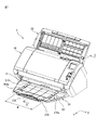
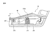
図1は、本実施形態の排紙トレイ装置20が取り付けられた画像読取装置1を示す斜視図である。図2は、図1のII−II線に沿った断面図であり、排紙トレイ装置20が画像読取装置1の読取装置本体10に取り付けられた状態を示す。
FIG. 1 is a perspective view showing an image reading apparatus 1 to which a paper
画像読取装置1は、原稿(以下、用紙40と呼ぶ)を搬送しながら画像として読み取る読取装置本体10と、複数枚の用紙40を連続して読取装置本体10に供給する給紙装置30と、読取装置本体10により読み取られた用紙40を排紙する排出口11と、排出口11から排紙された複数枚の用紙40を積載する排紙トレイ装置20とを備える。また、図示実施形態の画像読取装置1は、使用しない場合、排紙トレイ装置20を折り畳むことが可能になっており、全体としてコンパクトになるよう構成される。
The image reading device 1 includes a reading device
排紙トレイ装置20が取り付けられた画像読取装置1は一例であり、排出口11から用紙を排出する装置であれば、排紙トレイ装置20が取り付けられる装置は、インクジェットプリンター等の印刷装置や画像複写装置であってもよい。画像読取装置1の読取装置本体10が有する排紙機構や、給紙装置30の給紙機構は従来の機構と置き換え可能であるため、その詳細については説明を省略する。
The image reading device 1 to which the paper
排紙トレイ装置20は、画像読取装置1を使用する際、読取装置本体10と連結するアーム204に支持されて、用紙40を排出する読取装置本体10の排出口11の下方に設けられるよう構成される。排紙トレイ装置20は、排出された用紙40を積載するための積載面201aを有するトレイ本体201と、用紙40の排出方向(図1及び2の矢印Y方向)と直交する方向(図1の矢印X方向)に所定の間隔Wを開けて配置され、且つ、排出口11から用紙40が排出される際にトレイ本体201の積載面201aから突出する一対のリブ210a、210bとを備える。
The
また、突出する一対のリブ210a、210bのそれぞれは、排出口11から排出された用紙40をガイドするために、用紙40の排出方向の下流側から上流側に向けて次第に積載面201aからの高さが高くなる第一の傾斜面211を有する。また、一対のリブ210a、210bのそれぞれは、用紙の排出方向の上流側から下流側に向けて次第に積載面201aから突出する高さが高くなる第二の傾斜面212を有する。一対のリブ210a、210bは、それぞれの第一の傾斜面211と第二の傾斜面212との間の角度αが90度以上、すなわち鈍角となるように形成されている。
Each of the protruding pair of
一対のリブ210a、210bは、排出口11から排紙された用紙40が、図2に示すように排出時、一対のリブ210a、210bの第一の傾斜面211に着地するよう配置される。用紙は40の先端は、トレイ本体201の積載面201aに直接着地しない。また、第一の傾斜面211は傾斜していることから、用紙40が積載面201aに直接着地したときの着地角度より、第一の傾斜面に対する着地角度θを小さくすることができる。排出口11から排紙された用紙40の先端が第一の傾斜面211に着地するには、一対のリブ210a、210bの後端、すなわち下流側の端部の位置が、排出口11からの距離が0mm以上、30mm以下となるよう設置されるのがよい。
The pair of
第一の傾斜面211と第二の傾斜面212との間の角度αが鈍角となっていることにより、例えば、排出された用紙40の先端が下方にカールしている場合であっても、リブの頂部214に引っ掛かることがなく、第一の傾斜面211側に押し戻すことができ、腰折れを防止することができる。角度αが90度より小さい場合、用紙の先端が下方にカールしていると、第二の傾斜面212を下降するようになり腰折れする可能性がある。
Since the angle α between the first
また、一対のリブ210a、210bは、図1に示すように、所定の間隔Wを開けて配置される。この間隔Wは、排紙される頻度の高い用紙の大きさに基づくのが望ましく、用紙40の側部40a、40b(図3参照)のそれぞれが、第一の傾斜面211に当接するように決定される。対象となる用紙の大きさがA3サイズである場合、間隔Wを150mm以上、290mm以下の大きさとして、一対のリブ210a、210bを配置するのが好ましく、また、対象となる用紙の大きさがA4サイズである場合は、間隔Wを100mm以上、200mm以下の大きさとして、一対のリブ210a、210bを配置するのが好ましい。
Further, as shown in FIG. 1, the pair of
図3は一対のリブ210a、210bにより用紙が腰付けられた状態を示す模式図である。図3に示すように、所定の間隔Wを開けて、トレイ本体上に一対のリブ210a、210bを配置することで、排紙時において、用紙40はその側部40a、40bがリブ210a、210bにより支持され、用紙40が幅方向(図1の矢印X方向)において凹形状に曲がり腰付けされる。図3に示すように腰付けされた用紙40は、排紙方向(図1の矢印Y方向)に対しては曲がりにくくなることから、腰折れが防止される。
FIG. 3 is a schematic diagram showing a state in which the sheet is seated by the pair of
また、一対のリブ210a、210bは、トレイ本体201の排紙方向(図1の矢印Y方向)に沿った、排紙トレイ装置20の中央軸に対して線対称の位置に配置されている。これは、給紙装置30が用紙40を中央にあわせて給紙する方式であり、それに従って排紙トレイ装置20の中央を基準として排紙されるためである。給紙装置30が片側合わせ給紙方式である場合は、一対のリブは排紙の位置に合わせて配置される。
Further, the pair of
また、一対のリブ210a、210bは第一の傾斜面211の左右に傾斜して配置された両側面213を有する。両側面213が図3に示すように傾斜することで、例えば一対のリブ210a、210bの内側の間隔W2より、幅の大きさが若干大きい用紙が排紙された場合であっても、その用紙の両側部が対応する側面213に接触することで用紙が腰付けされると共に排紙時における用紙の先端に係る負荷が減少し、腰折れが防止されるようになる。
In addition, the pair of
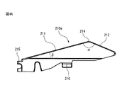
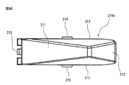
一対のリブ210a、210bのそれぞれは、トレイ本体201に収容可能に構成される。図4Aにトレイ本体201に取り付けられる前の状態のリブ210aの側面を、図4Bにリブ210aの平面を示す。リブ210bは、リブ210aと同じ形状で形成されるため、その説明は省略する。
Each of the pair of
図4A及び図4Bに示すように、リブ210aの底部には、排紙方向の下流側の端部に、トレイ本体201に形成された回転軸207(図5参照)を把持する把持部215と、リブ210aの底部の左右にストッパー216とが設けられている。
As shown in FIG. 4A and FIG. 4B, at the bottom of the
図5Aは、図1のV−V線に沿った断面図であり、リブ210aがトレイ本体201に取り付けられた状態を示す断面図である。図5Bは、リブ210aが、トレイ本体201に積載された用紙40の荷重により下がり、トレイ本体201の内部に収容された様子を示す図である。図5Aに示すように、リブ210aの把持部215はトレイ本体201に設けられた回転軸207を把持しており、リブ210aは、回転軸207を中心に、図5Aの矢印C方向に回動可能に取り付けられる。また、リブ210aの底部は、トレイ本体201に設けられたコイルばね217(弾性体)により支持されている。そのため、リブ210a上にある一定数の用紙が積載された場合でも、リブ210aの高さHは変化しない。そして、リブ210a上に積載される用紙40の枚数が所定数より増加すると、リブ210aは下方に回動し、リブ210aが突出する高さHが徐々に低くなる。そして、最終的には、リブ210aはトレイ本体内201に収容される。積載された用紙によりリブ210aの高さが減少するため、従来と同様の最大積載枚数を実現することができる。
5A is a cross-sectional view taken along line VV in FIG. 1, and is a cross-sectional view showing a state in which the
リブ210aを支持するコイルばね217は弾性体の一例であり、コイルばね217はゴムであってもよい。また、リブ210aの底部の左右には、トレイ本体201に当接するストッパー216が設けられているため、リブ210aはコイルばね217により上方に付勢されても、リブ210aがトレイ本体201から飛び出すことはない。
The
なお、図に示すリブ210aは、その回転軸207(支点)が排紙方向の下流側に設けられているが、回転軸207は上流側に設けてもよい。図示実施形態のように、回転軸207を下流側に設けた方が、積載された用紙40からの荷重を受けやすくリブ210aが容易に下がるので望ましい。
The
リブ210aが、積載面201aから突出する高さHは、用紙40に対して充分な腰付けを行うためには5mm以上であることが望ましい。リブ210aの高さHは、リブ210aがトレイ本体201内に収容されることを考慮して、トレイ本体201の厚さに応じて制限される。
The height H at which the
また、図に示すリブ210aの積載面201aに対する第一の傾斜面211の傾きの角度β(図4参照)は15度で形成されている。傾きの角度βは、排出された用紙40の先端が積載面201aに移動する際に腰折れしないよう、傾斜角度が10度以上、20度以下となるように形成するのがよい。
Further, the inclination angle β (see FIG. 4) of the first
次に、図1及び図2に戻り、排紙トレイ装置20が備えるフラップ部220について説明する。
Next, returning to FIGS. 1 and 2, the
本実施形態の排紙トレイ装置20は、トレイ本体201の排紙方向の下流側において、引き出し可能に設けられたスライドトレイ部202と、スライドトレイ部202がトレイ本体201から引き出される動作と連動して、傾斜位置に移動するフラップ部220を更に有する。
The paper
フラップ部220は、一対のリブ210a、210bに対して所定の幅Dを有する積載面201aの平坦部208を介して、用紙40の排出方向(矢印Y方向)の下流側に配置される。
The
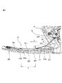
図6は、トレイ本体201に設けられたスライドトレイ部202を引き出した状態を示す、排紙トレイ装置20の斜視図であり、図7はその側面図である。
6 is a perspective view of the paper
スライドトレイ部202は、トレイ本体201からスライドする第一のスライド部202aと、第一のスライド部202aからスライドする第二のスライド部202bとから構成される。第二のスライド部202bの下流側の端部には、取っ手205が設けられ、使用者は取っ手205を引くことで、スライドトレイ部202をトレイ本体201から引き出すことができる。
The
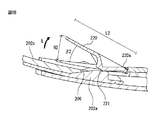
トレイ本体201のフラップ部220は、スライドトレイ部202が引き出されたときに、スライドトレイ部202と連動して傾斜位置に移動する。フラップ部220は、排出された用紙40をガイドするために、図6及び図7に示すように傾斜位置において、用紙の排出方向の上流側から下流側に向けて次第に積載面201aからの高さが高くなるよう配置される。
The
積載面201aに傾斜するフラップ部220があることで、図7に示すように、排紙された用紙40はフラップ部220により持ち上げられ、フラップ部220を乗り越えた用紙40は、一旦空中に浮き、スライドトレイ部202に着地する。この時、空中に浮いている用紙の面積分だけ、積載された用紙41との接触面積が減少する。接触面積が減少することから、積載された用紙41と排出される用紙40との間の摩擦力も減少するため、積載された用紙41は排出された用紙40により移動することがなく、押出しを軽減することができる。
As shown in FIG. 7, the
フラップ部220は、図6に示すように板状の部材であり、排出された用紙40を、その幅方向(図6の矢印X方向)において全体を持ち上げるよう構成される。用紙40を一旦、空中に浮かせるためには、幅方向の長さW3は50mm以上、排出方向の長さL2は20mm以上あるのが望ましい。
The
また、傾斜位置におけるフラップ部220の下流側の端部の、積載面からの高さH2は、10mm以上、40mm以下、傾斜角度β2(図8B参照)は10度以上、30度以下であるのが望ましい。高さH2が10mmより低いか、又は傾斜角度β2が10度より小さい場合は、用紙40を空中に浮かせる面積が少なくなり、用紙間の摩擦を減少させる効果を得ることが難しい。高さH2が40mmより高いか、又は傾斜角度β2が30度より大きい場合は、用紙40がフラップ部220を登ることができない。また空中に浮いた用紙40が急な角度でスライドトレイ部202に着地するため、用紙40の先端が腰折れしてしまう虞がある。
Further, the height H2 of the downstream end of the
フラップ部220を設置する位置は、A3サイズの用紙を対象としている場合、排出口11からフラップ部220の上流側端部までの長さL(図7参照)を80mm以上、160mm以下するのがよい。またA4サイズの用紙を対象としている場合、長さLを50mm以上、120mm以下とするのがよい。
When the A3 size paper is targeted, the position where the
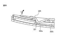
図8Aは、フラップ部220が排紙トレイ装置20のトレイ本体201に収容された状態を示す断面図であり、図8Bは、スライドトレイ部202が引き出され、フラップ部220が傾斜位置に移動した状態を示す断面図である。
FIG. 8A is a cross-sectional view showing a state in which the
図8A及び図8Bに示すように、フラップ部220はその背面においてフラップ部220を支持する支持部221を備えている。また、スライドトレイ部202の第一のスライド部202aは、その上流側の端部において、スライドトレイ部202が引き出されたときに、フラップ部220の支持部221と係合する突起部206を備えている。フラップ部220は、その支持部221と突起部206が係合すると、上流側の端部220aを回転軸として、矢印E方向に起き上がるように構成される。スライドトレイ部202を引き出すだけで、フラップ部220が傾斜位置にまで起き上がることから、使用者はフラップ部220を起こし忘れることがない。
As shown in FIGS. 8A and 8B, the
図7に示すようにフラップ部220により持ち上げられた積載された用紙41は、その凸状のふくらみにより、排紙が平坦に積載された場合と比較して、取り出しやすくなる。また、フラップ部220は、傾斜位置にあることで、例えばトレイ本体201の排紙方向の長さより短い用紙が排紙された場合、ストッパーとしての役割を果たす。
As shown in FIG. 7, the
図9は、図1〜図8に示す排紙トレイ装置20とは別の実施形態の排紙トレイ装置21を示す斜視図である。排紙トレイ装置21は、排紙トレイ装置20の代わりに、図1に示す画像読取装置1の排出口11の下方に設けることができる。排紙トレイ装置21は、排出された用紙40を積載するための積載面201aを有するトレイ本体201と、用紙40の排出方向(図9の矢印Y方向)と直交する方向に所定の間隔Wを開けて配置され、且つ、排出口11から用紙40が排出される際にトレイ本体201の積載面201aから突出する一対のリブ210a、210bを備える。また、トレイ本体201から引き出し可能に設けられたスライドトレイ部202を有する。スライドトレイ部202は、トレイ本体201からスライドする第一のスライド部202aと、第一のスライド部202aからスライドする第二のスライド部202bとから構成される。一方、排紙トレイ装置21は、図1〜図8に示す排紙トレイ装置20が備えるフラップ部220を備えていない。排紙トレイ装置21が備える一対のリブ210a、210bの形状や機能は排紙トレイ装置20の一対のリブ210a、210bと同様であるため、その説明は省略する。
FIG. 9 is a perspective view showing a paper
排紙トレイ装置21は、一対のリブ210a、210bを備えることにより、排紙された用紙40に対して腰付けすることができる。また、一対のリブ210a、210bのそれぞれが、排紙された用紙40をガイドする第一の傾斜面211を有することから、用紙40が排紙トレイ装置上に着地する際の着地角度が小さくなる。そのため、用紙40の腰折れが発生し難くなり、延いては排紙ジャムを防止することができる。
The paper
図10は、図1〜図8に示す排紙トレイ装置20とは別の実施形態の排紙トレイ装置22を示す斜視図である。排紙トレイ装置22は、排紙トレイ装置20の代わりに、画像読取装置1の排出口11の下方に設けることができる。排紙トレイ装置22は、排出された用紙40を積載するための積載面201aを有するトレイ本体201と、トレイ本体201から引き出し可能に設けられたスライドトレイ部202と、を有する。さらに、スライドトレイ部202がトレイ本体201から引き出される動作と連動して傾斜位置に移動するフラップ部220を備える。フラップ部220は、傾斜位置において、排出された用紙40をガイドするために、用紙40の排出方向(図10のY方向)の上流側から下流側に向けて次第に積載面201aからの高さが高くなるよう配置される。一方、排紙トレイ装置22は、図1〜図8に示す排紙トレイ装置20が備える一対のリブ210a、210bを備えていない。排紙トレイ装置22が備えるスライドトレイ部202及びフラップ部220の形状や機能は排紙トレイ装置20のスライドトレイ部202及びフラップ部220と同様であるため、その説明は省略する。
FIG. 10 is a perspective view showing a paper
排紙トレイ装置22は、積載面201aに、傾斜位置に移動するフラップ部220を備えることで、排紙された用紙40はフラップ部220により持ち上げられる。フラップ部220を乗り越えた用紙40は、一旦空中に浮き、スライドトレイ部202に着地する。この時、空中に浮いている用紙の面積分だけ、積載用紙との接触面積が減少する。接触面積が減少することから、積載された用紙と排出される用紙との間の摩擦力も減少するため、積載用紙は排紙により移動することがなく、押出しを軽減することができる。
The paper
なお、図1〜図8に示す実施形態の排紙トレイ装置20では、排出口11から排紙された用紙40は、一対のリブ210a、210bを経由して、さらにフラップ部220により持ち上げられる。そのため、図10に示す排紙トレイ装置22のようにフラップ部220のみが設けられる場合よりもさらに用紙40が波打つように積載される。そのため、用紙間の摩擦面積が減少し、排出紙の腰折れを防止するとともに、排出紙により積載紙の押出しも防止することができるようになる。
1 to 8, the
1 画像読取装置
10 読取装置本体
11 排出口
20、21、22 排紙トレイ装置
201 トレイ本体
201a 積載面
202 スライドトレイ部
202a 第一のスライド部
202b 第二のスライド部
204 アーム
205 取っ手
206 突起部
207 回転軸
208 平坦部
210a、210b リブ
211 第一の傾斜面
212 第二の傾斜面
213 側面
214 頂部
215 把持部
216 ストッパー
217 コイルばね(弾性体)
220 フラップ部
221 支持部
30 給紙装置
40 用紙
DESCRIPTION OF SYMBOLS 1
220
Claims (8)
排出された用紙を積載するための積載面を有するトレイ本体と、
用紙の排出方向と直交する方向に所定の間隔を開けて配置され、且つ、少なくとも前記排出口から用紙が排出される際に前記トレイ本体の前記積載面から突出する一対のリブと、
前記トレイ本体に引き出し可能に設けられたスライドトレイ部と、
前記トレイ本体に、前記一対のリブに対して、所定の幅を有する前記積載面の平坦部を介して、用紙の排出方向の下流側に配置されるフラップ部と、を備え、
前記一対のリブのそれぞれは、前記排出口から排出された用紙をガイドするために、用紙の排出方向の下流側から上流側に向けて次第に前記積載面からの高さが高くなるような第一の傾斜面を有し、
前記フラップ部は、用紙の排出方向の上流側から下流側に向けて次第に前記積載面からの高さが高くなるように配置され、
前記フラップ部は、前記スライドトレイ部が前記トレイ本体から引き出される動作と連動して傾斜位置に移動し、
前記フラップ部は、前記傾斜位置において、排出された用紙をガイドするために、用紙の排出方向の上流側から下流側に向けて次第に前記積載面からの高さが高くなるように配置される、ことを特徴とする排紙トレイ装置。 A paper discharge tray device provided below a discharge port for discharging paper,
A tray body having a stacking surface for stacking discharged paper;
A pair of ribs disposed at a predetermined interval in a direction perpendicular to the paper discharge direction, and protruding from the stacking surface of the tray body when the paper is discharged from at least the discharge port;
A slide tray provided in the tray body so as to be able to be drawn out;
A flap portion disposed on the tray body on the downstream side in the paper discharge direction via a flat portion of the stacking surface having a predetermined width with respect to the pair of ribs;
Each of the pair of ribs has a first height such that the height from the stacking surface gradually increases from the downstream side to the upstream side in the paper discharge direction in order to guide the paper discharged from the discharge port. Having an inclined surface
The flap portion is arranged so that the height from the stacking surface gradually increases from the upstream side to the downstream side in the paper discharge direction ,
The flap portion moves to an inclined position in conjunction with an operation in which the slide tray portion is pulled out from the tray body,
In the inclined position, the flap portion is arranged so that the height from the stacking surface gradually increases from the upstream side to the downstream side in the paper discharge direction in order to guide the discharged paper . A paper discharge tray device.
Priority Applications (3)
| Application Number | Priority Date | Filing Date | Title |
|---|---|---|---|
| JP2015216143A JP6238947B2 (en) | 2015-11-02 | 2015-11-02 | Output tray device |
| US15/174,878 US10087031B2 (en) | 2015-11-02 | 2016-06-06 | Paper ejection tray assembly with ribs |
| CN201610607200.2A CN106629200B (en) | 2015-11-02 | 2016-07-28 | Paper discharging tray device |
Applications Claiming Priority (1)
| Application Number | Priority Date | Filing Date | Title |
|---|---|---|---|
| JP2015216143A JP6238947B2 (en) | 2015-11-02 | 2015-11-02 | Output tray device |
Publications (2)
| Publication Number | Publication Date |
|---|---|
| JP2017088263A JP2017088263A (en) | 2017-05-25 |
| JP6238947B2 true JP6238947B2 (en) | 2017-11-29 |
Family
ID=58637266
Family Applications (1)
| Application Number | Title | Priority Date | Filing Date |
|---|---|---|---|
| JP2015216143A Active JP6238947B2 (en) | 2015-11-02 | 2015-11-02 | Output tray device |
Country Status (3)
| Country | Link |
|---|---|
| US (1) | US10087031B2 (en) |
| JP (1) | JP6238947B2 (en) |
| CN (1) | CN106629200B (en) |
Families Citing this family (7)
| Publication number | Priority date | Publication date | Assignee | Title |
|---|---|---|---|---|
| JP6806477B2 (en) * | 2016-07-19 | 2021-01-06 | キヤノン株式会社 | A sheet loading device and an image forming device including the sheet loading device. |
| JP6656202B2 (en) | 2017-04-27 | 2020-03-04 | 矢崎総業株式会社 | Routing material connection structure |
| JP6851911B2 (en) * | 2017-06-09 | 2021-03-31 | キヤノン株式会社 | Printing device |
| CN107337007B (en) * | 2017-08-22 | 2023-09-05 | 常州汉威信科技股份有限公司 | Chain hole paper bending and changing mechanism and paper tray using same |
| JP2020164307A (en) | 2019-03-29 | 2020-10-08 | 理想科学工業株式会社 | Paper discharge part |
| US11753267B2 (en) * | 2019-04-29 | 2023-09-12 | Hewlett-Packard Development Company, L.P. | Output tray fins |
| JP7367364B2 (en) * | 2019-07-22 | 2023-10-24 | セイコーエプソン株式会社 | media loading device |
Family Cites Families (30)
| Publication number | Priority date | Publication date | Assignee | Title |
|---|---|---|---|---|
| JPS57166262A (en) * | 1981-04-07 | 1982-10-13 | Fuji Xerox Co Ltd | Paper storing device of copier |
| JPH0395065A (en) * | 1989-09-06 | 1991-04-19 | Ricoh Co Ltd | Sheet exhaust device |
| JPH0616344A (en) * | 1992-07-03 | 1994-01-25 | Nisca Corp | Automatic document transporting device |
| JPH07179259A (en) * | 1993-12-24 | 1995-07-18 | Ricoh Co Ltd | Image forming device |
| JPH09156818A (en) | 1995-12-08 | 1997-06-17 | Fuji Photo Film Co Ltd | Sheet discharge tray |
| JPH11165935A (en) * | 1997-10-03 | 1999-06-22 | Ricoh Co Ltd | Paper exhaust tray and paper post-treatment device |
| JP3919139B2 (en) * | 1998-06-16 | 2007-05-23 | 株式会社リコー | Electrophotographic image forming apparatus |
| US6503011B2 (en) * | 1998-09-30 | 2003-01-07 | Canon Kabushiki Kaisha | Recording apparatus |
| JP3966530B2 (en) * | 1999-05-20 | 2007-08-29 | 株式会社リコー | Sheet stacking device |
| JP2001233527A (en) * | 2000-02-22 | 2001-08-28 | Riso Kagaku Corp | Sheet delivery device and printing device |
| US6659454B1 (en) | 2001-08-10 | 2003-12-09 | Lexmark International, Inc. | Printer exit tray and computer printer having an exit tray |
| JP2004026370A (en) * | 2002-06-24 | 2004-01-29 | Toshiba Tec Corp | Sheet discharging device and automatic manuscript feeding device |
| JP4188075B2 (en) * | 2002-12-27 | 2008-11-26 | ブラザー工業株式会社 | Image forming apparatus |
| JP4544925B2 (en) * | 2004-07-13 | 2010-09-15 | 京セラミタ株式会社 | Paper discharge tray |
| JP4804298B2 (en) | 2006-02-20 | 2011-11-02 | 京セラミタ株式会社 | Paper discharge tray and image forming apparatus having the same |
| JP4900929B2 (en) * | 2006-09-14 | 2012-03-21 | キヤノン電子株式会社 | Paper discharge tray, sheet material conveying apparatus, image reading apparatus, and image forming apparatus |
| JP5111155B2 (en) * | 2008-02-26 | 2012-12-26 | デュプロ精工株式会社 | Paper discharge device |
| JP2010265058A (en) * | 2009-05-13 | 2010-11-25 | Seiko Epson Corp | Recording device |
| JP2011241057A (en) * | 2010-05-19 | 2011-12-01 | Seiko Epson Corp | Recording medium stacker and recording apparatus |
| JP5602112B2 (en) * | 2011-08-26 | 2014-10-08 | シャープ株式会社 | Image forming apparatus |
| JP2013237544A (en) | 2012-05-16 | 2013-11-28 | Riso Kagaku Corp | Sheet ejection tray |
| JP5826155B2 (en) * | 2012-11-30 | 2015-12-02 | 京セラドキュメントソリューションズ株式会社 | Sheet stacking apparatus and image forming apparatus having the same |
| JP5836307B2 (en) * | 2013-04-05 | 2015-12-24 | 京セラドキュメントソリューションズ株式会社 | Paper discharge tray and image forming apparatus |
| JP6123456B2 (en) * | 2013-04-24 | 2017-05-10 | セイコーエプソン株式会社 | Recording device |
| JP6142640B2 (en) | 2013-04-24 | 2017-06-07 | セイコーエプソン株式会社 | Medium storage cassette and recording device |
| JP5804652B2 (en) * | 2013-04-25 | 2015-11-04 | 京セラドキュメントソリューションズ株式会社 | Image forming apparatus |
| JP6167970B2 (en) * | 2014-03-31 | 2017-07-26 | ブラザー工業株式会社 | Sheet transport device |
| JP2016101992A (en) * | 2014-11-27 | 2016-06-02 | キヤノン株式会社 | Sheet ejecting device and image forming apparatus |
| JP2016124642A (en) * | 2014-12-26 | 2016-07-11 | ブラザー工業株式会社 | Sheet transport device |
| JP6617438B2 (en) | 2015-05-29 | 2019-12-11 | ブラザー工業株式会社 | Sheet tray, conveying apparatus, and image recording apparatus |
-
2015
- 2015-11-02 JP JP2015216143A patent/JP6238947B2/en active Active
-
2016
- 2016-06-06 US US15/174,878 patent/US10087031B2/en active Active
- 2016-07-28 CN CN201610607200.2A patent/CN106629200B/en active Active
Also Published As
| Publication number | Publication date |
|---|---|
| US10087031B2 (en) | 2018-10-02 |
| CN106629200A (en) | 2017-05-10 |
| US20170121145A1 (en) | 2017-05-04 |
| JP2017088263A (en) | 2017-05-25 |
| CN106629200B (en) | 2018-06-22 |
Similar Documents
| Publication | Publication Date | Title |
|---|---|---|
| JP6238947B2 (en) | Output tray device | |
| JP4968923B2 (en) | Tabbed sheet support unit, sheet feeding apparatus, and image forming apparatus | |
| JP2017088262A (en) | Paper discharge tray device | |
| US9994411B2 (en) | Sheet tray, conveyance unit and image recording apparatus | |
| US8459639B2 (en) | Sheet conveyor device, image reading device, and image forming apparatus | |
| US8556250B2 (en) | Sheet feeding devices, image reading devices and image forming devices | |
| JP5871510B2 (en) | Sheet feeding apparatus and image forming apparatus | |
| JP2019089628A (en) | Medium feeding apparatus and image reading apparatus | |
| US8087662B2 (en) | Sheet feeder and image recording apparatus | |
| JP5993405B2 (en) | Sheet cassette, sheet feeding apparatus, and image forming apparatus | |
| JP6322902B2 (en) | Feeding device and image recording device | |
| US6296244B1 (en) | Method and apparatus for guiding media | |
| US20210373476A1 (en) | Medium ejection device and image forming apparatus | |
| JP4159561B2 (en) | Sheet stacking device | |
| JP6123659B2 (en) | Sheet conveying apparatus and image recording apparatus | |
| JP2014009067A (en) | Paper feeder and image recording device | |
| JP5707306B2 (en) | Sheet holding device and image reading apparatus and image forming apparatus provided with the same | |
| JP6711574B2 (en) | Sheet feeding device and printing device | |
| JP6756222B2 (en) | Paper feed device with paper stopper | |
| CN112277486B (en) | Medium accumulating and loading device | |
| JP7380285B2 (en) | Image forming device | |
| JP7277138B2 (en) | Feeder and recorder | |
| JP4475410B2 (en) | Recording material separating device, feeding cassette, recording device, and liquid ejecting device | |
| US20220097996A1 (en) | Printing apparatus | |
| JP6882058B2 (en) | Sheet storage device and printing device |
Legal Events
| Date | Code | Title | Description |
|---|---|---|---|
| A521 | Request for written amendment filed |
Free format text: JAPANESE INTERMEDIATE CODE: A523 Effective date: 20170215 |
|
| A02 | Decision of refusal |
Free format text: JAPANESE INTERMEDIATE CODE: A02 Effective date: 20170509 |
|
| A521 | Request for written amendment filed |
Free format text: JAPANESE INTERMEDIATE CODE: A523 Effective date: 20170808 |
|
| A911 | Transfer to examiner for re-examination before appeal (zenchi) |
Free format text: JAPANESE INTERMEDIATE CODE: A911 Effective date: 20170816 |
|
| TRDD | Decision of grant or rejection written | ||
| A01 | Written decision to grant a patent or to grant a registration (utility model) |
Free format text: JAPANESE INTERMEDIATE CODE: A01 Effective date: 20171003 |
|
| A61 | First payment of annual fees (during grant procedure) |
Free format text: JAPANESE INTERMEDIATE CODE: A61 Effective date: 20171031 |
|
| R150 | Certificate of patent or registration of utility model |
Ref document number: 6238947 Country of ref document: JP Free format text: JAPANESE INTERMEDIATE CODE: R150 |