JP6236857B2 - Pneumatic tire - Google Patents
Pneumatic tire Download PDFInfo
- Publication number
- JP6236857B2 JP6236857B2 JP2013096436A JP2013096436A JP6236857B2 JP 6236857 B2 JP6236857 B2 JP 6236857B2 JP 2013096436 A JP2013096436 A JP 2013096436A JP 2013096436 A JP2013096436 A JP 2013096436A JP 6236857 B2 JP6236857 B2 JP 6236857B2
- Authority
- JP
- Japan
- Prior art keywords
- tire
- line
- width direction
- main groove
- circumferential main
- Prior art date
- Legal status (The legal status is an assumption and is not a legal conclusion. Google has not performed a legal analysis and makes no representation as to the accuracy of the status listed.)
- Active
Links
Images


Description
本発明は、ウェット性能とドライ性能とをバランス良く改善した空気入りタイヤに関する。 The present invention relates to a pneumatic tire that improves wet performance and dry performance in a well-balanced manner.
従来、ウェット性能とドライ性能とを改善した空気入りタイヤが知られている(特許文献1参照)。特許文献1には、トレッド面のタイヤ幅方向最外側の主溝よりも内側に位置する主溝の溝幅及びポイントハイトの大きさを、それぞれ上記最外側の主溝の溝幅及びポイントハイトよりも小さくした重荷重用空気入りタイヤが開示されている。 Conventionally, a pneumatic tire which improved wet performance and dry performance is known (refer to patent documents 1). In Patent Document 1, the groove width and the point height of the main groove located on the inner side of the outermost main groove in the tire width direction of the tread surface are respectively set from the groove width and the point height of the outermost main groove. A heavy duty pneumatic tire is also disclosed.
特許文献1に開示された技術では、タイヤ周方向に延在する溝をジグザグ状にすることで、これらの溝によって区画形成された陸部のエッジ効果が確保され、優れた雪上制動性能が実現される。しかしながら、溝をジグザグ状に形成したことにより、陸部の剛性が十分に得られず、乾燥路面での優れた操縦安定性能が十分に発揮できるか不明である。 In the technique disclosed in Patent Document 1, by making the grooves extending in the tire circumferential direction into a zigzag shape, the edge effect of the land portion defined by these grooves is ensured, and excellent braking performance on snow is realized. Is done. However, it is unclear whether the grooves are formed in a zigzag shape so that the rigidity of the land portion cannot be sufficiently obtained and the excellent steering stability performance on the dry road surface can be sufficiently exhibited.
本発明は、上記事情に鑑みてなされたものであって、特に、雪上制動性能を維持しつつ、乾燥路面での操縦安定性能を改善した、空気入りタイヤを提供することを目的とする。 The present invention has been made in view of the above circumstances, and it is an object of the present invention to provide a pneumatic tire that improves driving stability performance on a dry road surface while maintaining braking performance on snow.
本発明に係る空気入りタイヤは、トレッド部に、タイヤ周方向に波状又はジグザグ状に延在する、少なくとも1本の周方向主溝が設けられた空気入りタイヤである。上記周方向主溝のタイヤ子午断面プロファイルラインは、タイヤ幅方向一方側の第1の開口端からタイヤ径方向内側に向かって溝底よりもタイヤ径方向外側で終端する第1のラインと、タイヤ幅方向他方側の第2の開口端からタイヤ径方向内側に向かって溝底まで延在する第2のラインと、上記第1のラインと上記第2のラインとの間のタイヤ幅方向領域に位置する第3のラインと、から構成されている。上記第1のラインのタイヤ幅方向に対する傾斜角は、タイヤ周方向で連続的に変動する。上記第2のラインのタイヤ幅方向位置は、タイヤ周方向で連続的に変動する。そして、トレッド表面のタイヤ径方向位置において、上記第1の開口端の実際のタイヤ幅方向位置から上記第2の開口端の実際のタイヤ幅方向位置までの線分がタイヤ周方向に連なる領域の面積は、上記第1の開口端が最も溝底側に位置する場合のタイヤ幅方向位置から上記第2の開口端の実際のタイヤ幅方向位置までの線分がタイヤ周方向に連なる領域の面積の、1.01倍より大きくかつ1.15倍未満である。 The pneumatic tire according to the present invention is a pneumatic tire in which at least one circumferential main groove extending in a wavy shape or a zigzag shape in the tire circumferential direction is provided in a tread portion. The tire meridional profile line of the circumferential main groove includes a first line that terminates from the first opening end on one side in the tire width direction toward the inside in the tire radial direction on the tire radial direction outer side than the groove bottom, and the tire In a tire width direction region between the second line extending from the second opening end on the other side in the width direction to the groove bottom toward the inside in the tire radial direction, and between the first line and the second line And a third line located. The inclination angle of the first line with respect to the tire width direction continuously varies in the tire circumferential direction. The position in the tire width direction of the second line continuously varies in the tire circumferential direction. And in the tire radial direction position of the tread surface, the line segment from the actual tire width direction position of the first opening end to the actual tire width direction position of the second opening end is a region continuous in the tire circumferential direction. The area is an area of a region where a line segment from the position in the tire width direction when the first opening end is located closest to the groove bottom to the actual tire width direction position of the second opening end is continuous in the tire circumferential direction. Is greater than 1.01 and less than 1.15 times.
本発明に係る空気入りタイヤでは、周方向主溝のタイヤ子午断面プロファイルラインについて改良を加えている。その結果、本発明に係る空気入りタイヤによれば、特に、雪上制動性能を維持しつつ、乾燥路面での操縦安定性能が改善される。 In the pneumatic tire according to the present invention, the tire meridional profile line of the circumferential main groove is improved. As a result, according to the pneumatic tire according to the present invention, in particular, the steering stability performance on the dry road surface is improved while maintaining the braking performance on snow.
以下に、本発明に係る空気入りタイヤの実施の形態(以下に示す、基本形態及び付加的形態1から6)を、図面に基づいて詳細に説明する。なお、これらの実施の形態は、本発明を限定するものではない。また、上記実施の形態の構成要素には、当業者が置換可能かつ容易なもの、或いは実質的に同一のものが含まれる。さらに、上記実施の形態に含まれる各種形態は、当業者が自明の範囲内で任意に組み合わせることができる。 DESCRIPTION OF EMBODIMENTS Hereinafter, embodiments of a pneumatic tire according to the present invention (basic forms and additional forms 1 to 6 shown below) will be described in detail with reference to the drawings. Note that these embodiments do not limit the present invention. In addition, the constituent elements of the above embodiment include those that can be easily replaced by those skilled in the art, or those that are substantially the same. Furthermore, various forms included in the above-described embodiment can be arbitrarily combined within a range obvious to those skilled in the art.
[基本形態]
以下に、本発明に係る空気入りタイヤについて、その基本形態を説明する。以下の説明において、タイヤ径方向とは、空気入りタイヤの回転軸と直交する方向をいい、タイヤ径方向内側とはタイヤ径方向において回転軸に向かう側、タイヤ径方向外側とはタイヤ径方向において回転軸から離れる側をいう。また、タイヤ周方向とは、上記回転軸を中心軸とする周り方向をいう。さらに、タイヤ幅方向とは、上記回転軸と平行な方向をいい、タイヤ幅方向内側とはタイヤ幅方向においてタイヤ赤道面CL(タイヤ赤道線)に向かう側、タイヤ幅方向外側とはタイヤ幅方向においてタイヤ赤道面CLから離れる側をいう。なお、タイヤ赤道面CLとは、空気入りタイヤの回転軸に直交するとともに、空気入りタイヤのタイヤ幅の中心を通る平面である。
[Basic form]
Below, the basic form is demonstrated about the pneumatic tire which concerns on this invention. In the following description, the tire radial direction means a direction orthogonal to the rotational axis of the pneumatic tire, the tire radial inner side is the side toward the rotational axis in the tire radial direction, and the tire radial outer side is in the tire radial direction. The side away from the rotation axis. The tire circumferential direction refers to a circumferential direction with the rotation axis as a central axis. Further, the tire width direction means a direction parallel to the rotation axis, the inner side in the tire width direction means the side toward the tire equatorial plane CL (tire equator line) in the tire width direction, and the outer side in the tire width direction means the tire width direction. Is the side away from the tire equatorial plane CL. The tire equatorial plane CL is a plane that is orthogonal to the rotational axis of the pneumatic tire and passes through the center of the tire width of the pneumatic tire.
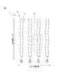
図1は、本発明の実施の形態に係る空気入りタイヤのトレッド部の一例を示す平面図である。同図に示す空気入りタイヤ1はトレッド部10を有する。トレッド部10は、ゴム材(トレッドゴム)からなり、空気入りタイヤ1のタイヤ径方向の最も外側で露出し、その表面が空気入りタイヤ1の輪郭となる。このトレッド部10の表面は、空気入りタイヤ1を装着する車両(図示せず)が走行した際に路面と接触する面であるトレッド表面12として形成されている。
FIG. 1 is a plan view showing an example of a tread portion of a pneumatic tire according to an embodiment of the present invention. The pneumatic tire 1 shown in the figure has a
トレッド表面12には、図1に示すように、タイヤ周方向に延在する溝14が設けられ、同図に示すトレッドパターンが形成されている。溝14の具体的構成は、以下のとおりである。
As shown in FIG. 1, the
即ち、トレッド表面12には、タイヤ赤道面CLについて対称である4本の周方向主溝14(14a、14b、14c、14d)が設けられている。これらの周方向主溝14a、14b、14c、14dは、いずれも、タイヤ周方向に対してジグザグ状に延在している。なお、図1に示す周方向主溝14(14a、14b、14c、14d)は、いずれも、そのタイヤ幅方向両端における陸部との境界線同士の位相が同一となっている。換言すれば、図1に示す周方向主溝14は、そのタイヤ幅方向寸法がタイヤ周方向において一定となっている。なお、周方向主溝14の幅は3mm以上20mm以下とすることができ、その深さは4mm以上10mm以下とすることができる。
That is, the
図2は、図1の点線部を示す拡大図である。図2中、線分B1、B2は、それぞれ、トレッド表面12における周方向主溝14cと陸部との境界線である。本実施の形態において、周方向主溝14cは、図2に示すように、境界線B1からタイヤ幅方向一方側に境界線B2まで連続する、溝壁GWa、溝壁GWb、溝底GB及び溝壁GWcにより構成されている。
FIG. 2 is an enlarged view showing a dotted line portion of FIG. In FIG. 2, line segments B <b> 1 and B <b> 2 are boundary lines between the circumferential
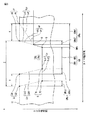
図3は、図2のA−A´線に沿うタイヤ子午断面の一部についてのタイヤ周方向における変動状態を示す拡大図である。図3において、溝壁GWaは線分Laで示され、溝壁GWcは線分Lbで示され、溝壁GWbと溝底GBとからなる部分は線分Lcで示されている。 FIG. 3 is an enlarged view showing a variation state in the tire circumferential direction of a part of the tire meridional section along the line AA ′ in FIG. 2. In FIG. 3, the groove wall GWa is indicated by a line segment La, the groove wall GWc is indicated by a line segment Lb, and a portion composed of the groove wall GWb and the groove bottom GB is indicated by a line segment Lc.
本実施の形態においては、図3に示すように、周方向主溝14cのタイヤ子午断面プロファイルラインは、タイヤ幅方向一方側の第1の開口端Pからタイヤ径方向内側に向かって溝底GBよりもタイヤ径方向外側の点Rで終端する第1のラインLaと、タイヤ幅方向他方側の第2の開口端Qからタイヤ径方向内側に向かって溝底GBの点Tまで延在する第2のラインLbと、第1のラインLaと第2のラインLbとの間のタイヤ幅方向領域に位置する第3のラインLcと、から構成されている。なお、図3において、周方向主溝14cがタイヤ周方向に連続的に延在する際に変動しない部分は実線で、また変動する部分は点線で、それぞれ示されている。
In the present embodiment, as shown in FIG. 3, the tire meridional profile line of the circumferential
周方向主溝14cがタイヤ周方向(図3の紙面に垂直な方向)に連続的に延在していくと、第1の開口端Pは、図3に示すように、点P1から点P2までの間を変動幅Xで連続的に変動する。また、周方向主溝14cがタイヤ周方向に連続的に延在していくと、第2の開口端Qは、図3に示すように、点Q1から点Q2までの間を変動幅Yで連続的に変動する。
When the circumferential
そして、周方向主溝14cがタイヤ周方向に連続的に延在していくと、第1のラインLa(点Pと点Rとを結ぶ線分)は、図3に示すように、ラインLa1(点P1と点Rとを結ぶ線分)からラインLa2(点P2と点Rとを結ぶ線分)まで連続的に変動する。このとき、第1のラインLaのタイヤ幅方向に対する傾斜角θは、図3に示すように、角度θ1から角度θ2まで連続的に変動する。
Then, when the circumferential
また、周方向主溝14cがタイヤ周方向に連続的に延在していくと、第2のラインLb(点Qと点Tとを結ぶ線分)は、図3に示すように、ラインLb1(点Q1と点T1とを結ぶ線分)からラインLb2(点Q2と点T2とを結ぶ線分)まで連続的に変動する。このとき、第2のラインLbのタイヤ幅方向位置は、第2の開口端Qの位置によって決定される。
In addition, when the circumferential
さらに、周方向主溝14cがタイヤ周方向に連続的に延在していくと、第3のラインLc(点Rから溝底の点Sを介して点Tまでの線分)は、図3に示すように、ラインLc1(点Rから溝底の点Sを介して点T1までの線分)からラインLc2(点Rから溝底の点Sを介して点T2までの線分)まで連続的に変動する。
Further, when the circumferential
ここで、トレッド表面12のタイヤ径方向位置において、第1の開口端Pの実際のタイヤ幅方向位置(点P1から点P2まで変動)から第1の開口端Pが最も溝底側に位置する場合のタイヤ幅方向位置である点P2までの線分Xがタイヤ周方向に連なる領域を、第1の領域と定義する。また、トレッド表面12のタイヤ径方向位置において、第1の開口端Pが最も溝底側に位置する場合のタイヤ幅方向位置である点P2から第2の開口端Qの実際のタイヤ幅方向位置(点Q1から点Q2まで変動)までの線分Zがタイヤ周方向に連なる領域を、第2の領域と定義する。
Here, in the tire radial direction position of the
図4は、図2に示す周方向主溝14cを、第1の領域と第2の領域とに区分けして示す平面図である。即ち、図4において、点線の右側の領域(斜線部分)を第1の領域14c1とするとともに、点線の左側の領域を第2の領域14c2とする。なお、図4に示す実線は、図2に示す実線と同じであり、これらの実線は溝底における各部(溝壁GWa、溝壁GWb、溝底GB、溝壁GWc)の境界線である。また、図4に示すタイヤ幅方向線分X、Zは、それぞれ、図3に示す線分X、Zである。
FIG. 4 is a plan view showing the circumferential
これらの定義を前提に、本実施の形態においては、図4に示す第1の領域14c1の面積と第2の領域14c2の面積との和が、第2の領域14c2の面積の1.01倍より大きくかつ1.15倍未満となっている。 Based on these definitions, in the present embodiment, the sum of the area of the first region 14c1 and the area of the second region 14c2 shown in FIG. 4 is 1.01 times the area of the second region 14c2. It is larger and less than 1.15 times.
(作用等)
一般に、雪上制動性能を改善するために陸部のエッジ効果を高めるべく、周方向主溝を波状又はジグザグ状に形成した場合には、周方向主溝を直線状に形成した場合と比較して、陸部の剛性が低下する。このような事情に鑑み、本実施の形態に係る空気入りタイヤでは、上記のとおり、周方向主溝のタイヤ子午断面プロファイルラインを、図3に示すような3つの変動ラインLa、Lb、Lcから構成することを前提に、第1のラインLaのタイヤ幅方向に対する傾斜角θを角度θ1から角度θ2まで、タイヤ周方向で連続的に変動させている。これにより、図3において点P1と点Rとを結んだ線分La1がタイヤ周方向で変動せずに連続的に延在する場合、即ち、点Pから点Rまでの第1のラインLaの角度θがタイヤ周方向において変動しない場合、と比べて、第1のラインLaにより区画形成される陸部の体積を大きく確保することができる。その結果、陸部の剛性を高め、ひいては乾燥路面での操縦安定性能を改善することができる。
(Action etc.)
In general, in order to improve the edge effect of the land part to improve the braking performance on snow, when the circumferential main groove is formed in a wave shape or zigzag shape, compared with the case where the circumferential main groove is formed in a straight line. , The rigidity of the land portion decreases. In view of such circumstances, in the pneumatic tire according to the present embodiment, as described above, the tire meridional profile line of the circumferential main groove is derived from three fluctuation lines La, Lb, and Lc as shown in FIG. On the premise of the configuration, the inclination angle θ of the first line La with respect to the tire width direction is continuously changed in the tire circumferential direction from the angle θ1 to the angle θ2. Thereby, in FIG. 3, when the line segment La1 connecting the point P1 and the point R extends continuously without changing in the tire circumferential direction, that is, the first line La from the point P to the point R Compared with the case where the angle θ does not vary in the tire circumferential direction, it is possible to ensure a large volume of the land portion defined by the first line La. As a result, the rigidity of the land portion can be increased, and consequently the steering stability performance on the dry road surface can be improved.
そして、第1のラインLaのタイヤ幅方向に対する傾斜角θを、上記のとおりタイヤ周方向で連続的に変動させることにより、周方向主溝14c内に雪を溜まり難くすることができ、排雪効果を高めることができる。なお、この効果は、 周方向主溝14c内で固められた雪をタイヤ周方向において断ち切る力である、せん断力が最も大きく作用する車両直進時に、特に高いレベルで奏される。
Then, by continuously varying the inclination angle θ of the first line La with respect to the tire width direction in the tire circumferential direction as described above, it is possible to make it difficult for snow to accumulate in the circumferential
また、本実施の形態に係る空気入りタイヤでは、図3に示すように、第2のラインLbのタイヤ幅方向位置を、タイヤ周方向で連続的に変動させている。これにより、第2のラインLbにより区画形成された陸部のエッジ効果を高めて、雪上制動性能を高めることができる。 In the pneumatic tire according to the present embodiment, as shown in FIG. 3, the position in the tire width direction of the second line Lb is continuously varied in the tire circumferential direction. Thereby, the edge effect of the land part partitioned by the 2nd line Lb can be improved, and the braking performance on snow can be improved.
そして、第2のラインLbのタイヤ幅方向位置を、タイヤ周方向で連続的に変動させることにより、周方向主溝14c内に雪を溜まり難くすることができ、排雪効果を高めることができる。
Then, by continuously changing the position in the tire width direction of the second line Lb in the tire circumferential direction, it is possible to make it difficult for snow to accumulate in the circumferential
さらに、本実施の形態に係る空気入りタイヤでは、図4に示すように、第1の領域14c1の面積と第2の領域14c2の面積との和を、第2の領域14c2の面積の1.01倍より大きくすることで、第1のラインLaの上記傾斜角を変動させることによる、乾燥路面での操縦安定性能の改善効果と、排雪効果とを十分に実現することができる。なお、第1の領域14c1の面積と第2の領域14c2の面積との和を、第2の領域14c2の面積の1.03倍以上とすることで、上記効果をより高いレベルで奏することができる。ここで、第1の領域14c1の面積及び第2の領域14c2の面積は、いずれも、2次元CADを用いて空気入りタイヤのパターン図を作成し、このパターン図から算出した面積である。 Furthermore, in the pneumatic tire according to the present embodiment, as shown in FIG. 4, the sum of the area of the first region 14c1 and the area of the second region 14c2 is set to 1. of the area of the second region 14c2. By making it larger than 01 times, it is possible to sufficiently realize the improvement effect of the steering stability performance on the dry road surface and the snow removal effect by changing the inclination angle of the first line La. Note that the above effect can be achieved at a higher level by setting the sum of the area of the first region 14c1 and the area of the second region 14c2 to 1.03 times or more of the area of the second region 14c2. it can. Here, the area of the first region 14c1 and the area of the second region 14c2 are areas calculated from a pattern diagram of a pneumatic tire created using a two-dimensional CAD.
そして、第1の領域14c1の面積と第2の領域14c2の面積との和を、第2の領域14c2の面積の1.15倍未満とすることで、周方向主溝14cの溝幅を過度に大きくすることなく、陸部の剛性の低下を抑制し、乾燥路面での操縦安定性能の劣化を防止することができる。なお、第1の領域14c1の面積と第2の領域14c2の面積との和を、第2の領域14c2の面積の1.10倍以下とすることで、上記効果をより高いレベルで奏することができる。
Then, by making the sum of the area of the first region 14c1 and the area of the second region 14c2 less than 1.15 times the area of the second region 14c2, the groove width of the circumferential
以上に示すように、本実施の形態に係る空気入りタイヤによれば、周方向主溝のタイヤ子午断面プロファイルラインについて改良を加えることにより、特に、雪上制動性能を維持しつつ、乾燥路面での操縦安定性能が改善される。 As described above, according to the pneumatic tire according to the present embodiment, by improving the tire meridional profile line of the circumferential main groove, particularly on a dry road surface while maintaining braking performance on snow. Steering stability is improved.
なお、以上に示す、本実施の形態の空気入りタイヤは、通常の各製造工程、即ち、タイヤ材料の混合工程、タイヤ材料の加工工程、グリーンタイヤの成型工程、加硫工程及び加硫後の検査工程等を経て得られるものである。本実施の形態の空気入りタイヤを製造する場合には、特に、加硫用金型の内壁に、図1から図4に示す周方向主溝14cに対応する凸部を形成し、この金型を用いて加硫を行う。
In addition, the pneumatic tire of the present embodiment described above is a normal manufacturing process, that is, a tire material mixing process, a tire material processing process, a green tire molding process, a vulcanization process, and a vulcanized process. It is obtained through an inspection process. When manufacturing the pneumatic tire of the present embodiment, in particular, a convex portion corresponding to the circumferential
また、以上に示す例は、図1の周方向主溝14cが図2から図4に示す特別な構成を有する例であるが、本実施の形態はこれに限られない。例えば、図1に示す周方向主溝14a、14b、14c、14dの少なくともいずれかが、図2から図4に示す形状の周方向主溝であればよい。特に、図2から図4に示す形状の周方向主溝を3本以上有することが、雪上制動性能の維持及び乾燥路面での操縦安定性能の改善が高いレベルで奏される点で好ましい。
Moreover, although the example shown above is an example which the circumferential direction
さらに、以上に示す例は、図1に示すとおり、タイヤ赤道面CLに対して非対称なトレッドパターンであるが、本実施の形態はこれに限られない。即ち、本実施の形態には、タイヤ赤道面CLに対して対称なトレッドパターン(線対称パターン)や、タイヤ赤道面CL上の任意の点に対して対称であるトレッドパターン(点対称パターン)も含まれる。 Furthermore, although the example shown above is a tread pattern asymmetric with respect to the tire equatorial plane CL as shown in FIG. 1, this Embodiment is not restricted to this. That is, the present embodiment also includes a tread pattern (line symmetric pattern) that is symmetric with respect to the tire equator plane CL and a tread pattern (point symmetric pattern) that is symmetric with respect to any point on the tire equator plane CL. included.
[付加的形態]
次に、本発明に係る空気入りタイヤの上記基本形態に対して、任意選択的に実施可能な、付加的形態1から6を説明する。
[Additional form]
Next, additional modes 1 to 6 that can be optionally implemented with respect to the basic mode of the pneumatic tire according to the present invention will be described.
(付加的形態1)
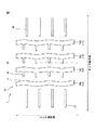
図5は、本発明の実施の形態に係る空気入りタイヤのトレッド部の一例を示す平面図である。同図に示す参照符号中、図1に示す参照符号と同一の参照符号については、図1に示す構成要素と同じ構成要素を示す。図5に示す例は、図1に示す例に対して、トレッド表面12に、さらに、ラグ溝(第1の幅方向溝16、第2の幅方向溝18)を設けた例である。
(Additional form 1)
FIG. 5 is a plan view showing an example of a tread portion of the pneumatic tire according to the embodiment of the present invention. Among the reference numerals shown in the figure, the same reference numerals as those shown in FIG. 1 denote the same components as those shown in FIG. The example shown in FIG. 5 is an example in which lug grooves (first
即ち、図5に示す例では、トレッド表面12には、周方向主溝14b、14c、14dのそれぞれから周方向主溝14a側に延在して陸部内で終端する第1の幅方向溝16が、タイヤ周方向に一定のピッチで複数形成されている。そして、トレッド表面12には、タイヤ幅方向外側の両周方向主溝14a、14dのタイヤ幅方向外側に、第1の幅方向溝16よりも長く、その両端が陸部内で終端する第2の幅方向溝18が、タイヤ周方向に一定のピッチで複数形成されている。なお、第1の幅方向溝16の幅は2mm以上8mm下とすることができ、その深さは1mm以上6mm以下とすることができる。また、第2の幅方向溝18の幅は2mm以上8mm以下とすることができ、その深さは1mm以上6mm以下とすることができる。
That is, in the example shown in FIG. 5, the
基本形態においては、図5に示すように、ラグ溝16、18がさらに設けられ、同図に示す周方向主溝14(14a、14b、14c、14d)の面積が、同図に示すラグ溝16、18の面積の1倍より大きく3倍未満であること(付加的形態1)が好ましい。本実施の形態において、周方向主溝とは、図1に示す周方向主溝14(14a、14b、14c、14d)のうち、図2から図4に示す形状を有する周方向主溝(以下、「特定周方向主溝」と称する場合がある)をいう。なお、本実施の形態において、周方向主溝14の面積とラグ溝16、18の面積との具体的な比較対象は、図5に示す全領域における、溝14の合計面積と、溝16、18の合計面積と、である。
In the basic configuration, as shown in FIG. 5, lug
特定周方向主溝の面積を、ラグ溝16、18の面積の1倍より大きくすることで、特定周方向主溝のタイヤ幅方向寸法を十分に確保することができる。その結果、上記した雪上制動性能の維持効果及び乾燥路面での操縦安定性能の改善効果をさらに高めることができる。
By making the area of the specific circumferential main groove larger than one area of the
また、特定周方向主溝の面積を、ラグ溝16、18の面積の3倍未満とすることで、特定周方向溝の溝幅を過度に大きくすることを抑制することができる。その結果、陸部の剛性の低下を抑制し、乾燥路面での操縦安定性能の劣化を防止することができるとともに、ラグ溝16、18のタイヤ幅方向寸法を十分に確保し、排雪効果をさらに高めることができる。
Moreover, it can suppress that the groove width of a specific circumferential direction groove | channel is enlarged too much by making the area of a specific circumferential direction main groove into less than 3 times the area of the
なお、特定周方向主溝の面積を、ラグ溝16、18の面積の1.5倍以上2.5倍以下とすることで、上記効果をそれぞれ、より高いレベルで奏することができる。
In addition, the said effect can each be show | played by a higher level by making the area of a specific circumferential direction main groove into 1.5 times or more 2.5 times or less of the area of the
(付加的形態2)
基本形態及び基本形態に付加的形態1を加えた形態においては、特定周方向主溝の最大幅が5mmより大きく15mm未満であること(付加的形態2)が好ましい。ここで、特定周方向主溝の最大幅とは、特定周方向主溝の延在方向に垂直な方向における最大寸法をいう。
(Additional form 2)
In the basic form and the form in which the additional form 1 is added to the basic form, it is preferable that the maximum width of the specific circumferential main groove is greater than 5 mm and less than 15 mm (additional form 2). Here, the maximum width of the specific circumferential main groove refers to the maximum dimension in a direction perpendicular to the extending direction of the specific circumferential main groove.
特定周方向主溝の最大幅を5mmより大きくすることで、特定周方向主溝のタイヤ幅方向寸法を十分に確保することができる。その結果、上記した雪上制動性能の維持効果及び乾燥路面での操縦安定性能の改善効果をさらに高めることができる。 By making the maximum width of the specific circumferential main groove larger than 5 mm, the tire width direction dimension of the specific circumferential main groove can be sufficiently secured. As a result, it is possible to further enhance the effect of maintaining the braking performance on snow and the improvement of the steering stability performance on the dry road surface.
特定周方向主溝の最大幅を15mm未満とすることで、特定周方向溝の溝幅を過度に大きくすることを抑制することができる。その結果、陸部の剛性の低下を抑制し、乾燥路面での操縦安定性能の劣化を防止することができる。また、特定周方向主溝の配設領域を小さくすることで、ラグ溝16、18の配設領域を大きく確保することができ、例えばラグ溝16、18のタイヤ幅方向寸法を大きく確保し、排雪効果をさらに高めることができる。
By making the maximum width of the specific circumferential direction main groove less than 15 mm, it is possible to suppress an excessive increase in the groove width of the specific circumferential direction groove. As a result, it is possible to suppress a decrease in rigidity of the land portion and to prevent deterioration of the steering stability performance on the dry road surface. Further, by reducing the arrangement area of the specific circumferential main groove, it is possible to ensure a large arrangement area of the
なお、特定周方向主溝の最大幅を、8mm以上12mm以下とすることで、上記効果をそれぞれ、より高いレベルで奏することができる。 In addition, the said effect can each be show | played by a higher level by making the maximum width of a specific circumferential direction main groove into 8 mm or more and 12 mm or less.
(付加的形態3)
図6は、本発明の実施の形態に係る空気入りタイヤのトレッド部の一例を示す平面図である。同図に示す参照符号中、図1に示す参照符号と同一の参照符号については、図1に示す構成要素と同じ構成要素を示す。図6に示す例は、図1に示す例に対して、周方向主溝14(14eから14h)の形状を異ならせた例である。
(Additional form 3)
FIG. 6 is a plan view showing an example of a tread portion of the pneumatic tire according to the embodiment of the present invention. Among the reference numerals shown in the figure, the same reference numerals as those shown in FIG. 1 denote the same components as those shown in FIG. The example shown in FIG. 6 is an example in which the shape of the circumferential main groove 14 (14e to 14h) is different from the example shown in FIG.
即ち、図6に示す例では、空気入りタイヤ2はトレッド部11を有し、その表面は空気入りタイヤ2を装着する車両(図示せず)が走行した際に路面と接触する面であるトレッド表面13として形成されている。そして、図6に示す空気入りタイヤ2においては、周方向主溝14(14e、14f、14g、14h)のタイヤ幅方向両端における陸部との境界線同士の位相が、図1に示す空気入りタイヤ1における場合と異なり、同一でない。なお、以下では、図6に示す周方向主溝14gが特定周方向主溝(図2から図4に示す形状を有する周方向主溝)であると仮定して説明する。
That is, in the example shown in FIG. 6, the
基本形態及び基本形態に付加的形態1、2の少なくともいずれかを加えた形態においては、図6に示すように、特定周方向主溝のタイヤ幅方向両端における陸部との境界線同士の位相が同一でないこと(付加的形態3)が好ましい。
In the basic form and the form obtained by adding at least one of the
周方向主溝14gのタイヤ幅方向両端における陸部との境界線同士の位相を異ならせることで、周方向主溝14gのタイヤ幅方向寸法がタイヤ周方向において連続的に変動し、当該寸法が比較的大きなタイヤ周方向位置(大幅周方向位置)や当該寸法が比較的小さなタイヤ周方向位置(小幅周方向位置)が局所的に現れる。その結果、小幅周方向位置に入り込んで一旦固められた雪が、タイヤの転動と同時に、大幅周方向位置側に移動することによって周方向主溝14gから抜けやすくなり、ひいては排雪効果をさらに高めることができる。
By differentiating the phases of the boundary lines with the land portions at both ends in the tire width direction of the circumferential
また、周方向主溝14gのタイヤ幅方向両端における陸部との境界線同士の位相を異ならせることで、タイヤ周方向位置の少なくとも一部において、上記境界線同士が、溝幅方向中心線に対して線対称となる部分が現れる。これにより、このようなタイヤ周方向位置においては、周方向主溝14gの両側に区画形成された陸部に、同一のタイヤ幅方向成分を有するエッジが形成される。その結果、エッジ効果が増強され、タイヤ転動時に効率的に雪を引っ掻くことができ、ひいては雪上での制動性能をさらに高めることができる。
Further, by making the phases of the boundary lines with the land portions at both ends in the tire width direction of the circumferential
(付加的形態4)
基本形態及び基本形態に付加的形態1から3の少なくともいずれかを加えた形態においては、図3に示す第1の開口端Pの変動幅Xが1mmより大きく5mm未満であること(付加的形態4)が好ましい。
(Additional form 4)
In the basic form and the form obtained by adding at least one of the additional forms 1 to 3 to the basic form, the variation width X of the first opening end P shown in FIG. 3 is greater than 1 mm and less than 5 mm (additional form). 4) is preferred.
第1の開口端Pの変動幅Xを1mmより大きくすることで、図3に示す第1のラインLaのタイヤ幅方向に対する傾斜角θをタイヤ周方向において十分に変動させることができ、ひいては操縦安定性能をさらに高めるとともに、排雪効果をさらに大きくすることができる。 By making the variation width X of the first opening end P larger than 1 mm, the inclination angle θ of the first line La shown in FIG. 3 with respect to the tire width direction can be sufficiently varied in the tire circumferential direction, and as a result While further improving the stability performance, the snow removal effect can be further increased.
また、第1の開口端Pの変動幅Xを5mm未満とすることで、図3に示す第1の開口端Pの接地圧をタイヤ周方向において過度に変動させることなく、コーナリングパワーを十分に発生させることができる。また、変動幅Xを5mm未満とすることで、第1の開口端P側に区画形成される陸部の体積を過度に小さくすることを抑制して、当該陸部の剛性を十分に確保することができる。従って、上記コーナリングパワーの発生及び上記陸部の剛性確保により、操縦安定性能をさらに高めることができる。 Further, by setting the fluctuation width X of the first opening end P to be less than 5 mm, the cornering power can be sufficiently increased without excessively changing the ground contact pressure of the first opening end P shown in FIG. 3 in the tire circumferential direction. Can be generated. In addition, by setting the fluctuation width X to be less than 5 mm, it is possible to suppress excessively reducing the volume of the land portion that is partitioned on the first opening end P side, and sufficiently ensure the rigidity of the land portion. be able to. Therefore, the steering stability performance can be further enhanced by generating the cornering power and ensuring the rigidity of the land portion.
(付加的形態5)
基本形態及び基本形態に付加的形態1から4の少なくともいずれかを加えた形態においては、図3に示す第2の開口端Qの変動幅Yが1mmより大きく5mm未満であること(付加的形態5)が好ましい。
(Additional form 5)
In the basic form and the form obtained by adding at least one of the additional forms 1 to 4 to the basic form, the variation width Y of the second opening end Q shown in FIG. 3 is greater than 1 mm and less than 5 mm (additional form). 5) is preferred.
第2の開口端Qの変動幅Yを1mmより大きくすることで、図3に示す第2のラインLbのタイヤ幅方向位置を十分に変動させることができ、ひいては雪上制動性能をさらに高めるとともに、排雪効果をさらに大きくすることができる。 By making the fluctuation width Y of the second opening end Q larger than 1 mm, the position in the tire width direction of the second line Lb shown in FIG. 3 can be sufficiently changed, and the braking performance on snow is further improved. The snow removal effect can be further increased.
また、第2の開口端Qの変動幅Xを5mm未満とすることで、図3に示す第2の開口端Qの接地圧をタイヤ周方向において過度に変動させることなく、コーナリングパワーを十分に発生させることができる。また、変動幅Yを5mm未満とすることで、第2の開口端Q側に区画形成される陸部の体積を過度に小さくすることを抑制して、当該陸部の剛性を十分に確保することができる。従って、上記コーナリングパワーの発生及び上記陸部の剛性確保により、操縦安定性能をさらに高めることができる。 Further, by making the fluctuation width X of the second opening end Q less than 5 mm, the cornering power can be sufficiently increased without excessively changing the ground contact pressure of the second opening end Q shown in FIG. 3 in the tire circumferential direction. Can be generated. Moreover, by making the fluctuation width Y less than 5 mm, it is possible to suppress the volume of the land portion partitioned and formed on the second opening end Q side from being excessively small, and sufficiently ensure the rigidity of the land portion. be able to. Therefore, the steering stability performance can be further enhanced by generating the cornering power and ensuring the rigidity of the land portion.
(付加的形態6)
図7は、本発明の実施の形態に係る空気入りタイヤのトレッド部の一例を示す平面図である。同図に示す参照符号中、図1、図5に示す参照符号と同一の参照符号については、図1、図5に示す構成要素と同じ構成要素を示す。図7に示す例は、図5に示す例に対して、トレッド表面12に、さらに、サイプ(第1のサイプ20、第2のサイプ22)を設けた例である。
(Additional form 6)
FIG. 7 is a plan view showing an example of a tread portion of the pneumatic tire according to the embodiment of the present invention. Among the reference numerals shown in the figure, the same reference numerals as those shown in FIGS. 1 and 5 indicate the same components as those shown in FIGS. 1 and 5. The example shown in FIG. 7 is an example in which sipes (
即ち、図7に示す例では、トレッド表面12には、周方向主溝14b、14c、14dのそれぞれから周方向主溝14a側に延在して陸部内で終端する第1のサイプ20が、タイヤ周方向に一定のピッチで複数形成されている。そして、トレッド表面12には、タイヤ幅方向外側の両周方向主溝14a、14dのそれぞれからタイヤ幅方向外側に延在し、第1のサイプ20よりも長く、そのタイヤ幅方向外端が陸部内で終端する第2のサイプ22が、タイヤ周方向に一定のピッチで複数形成されている。
That is, in the example shown in FIG. 7, the
ここで、第1のサイプ20及び第2のサイプ22は、いずれも、エッジ効果を高めるための構成要素である。サイプ20、22は、図7に示すように、少なくともそのタイヤ幅方向一端が周方向主溝14と連通していてもよいし、連通していなくてもよい。また、サイプ20、22は、図7に示すように、タイヤ幅方向に直線状に延在するものであってもよいし、タイヤ幅方向にジグザグ状に延在するものであってもよい。なお、サイプ20、22の幅は0.3mm以上2.0mm以下とすることができ、その深さは3.0mm以上7.0mm以下とすることができる。また、サイプ20、22がトレッド表面12付近で面取りされている場合には、上記サイプの幅は、当該面取り部分よりもタイヤ径方向内側で測定した寸法とする。
Here, the
基本形態及び基本形態に付加的形態1から5の少なくともいずれかを加えた形態においては、図7に示すように、トレッド表面12に、少なくとも1本のサイプ20、22が形成されていること(付加的形態6)が好ましい。トレッド表面12に、少なくとも1本のサイプ20、22を形成することで、エッジ効果がさらに増強され、タイヤ転動時に効率的に雪を引っ掻くことができ、ひいては雪上での制動性能をさらに高めることができる。
In the basic form and the form obtained by adding at least one of the additional forms 1 to 5 to the basic form, at least one
タイヤサイズを225/45R17とし、図7のトレッドパターンを有するとともに全ての周方向主溝14が図2から図4に示す構造(タイプ1)か、或いは、図7の周方向主溝14を図6の周方向主溝14に置き換えたこと以外はタイプ1と同じ構造(タイプ2)、のいずれかを有するとともに、全ての周方向主溝について、表1に示す諸条件(図4に示す第2の領域の面積に対して同図に示す第1の領域の面積と第2の領域の面積との和が何倍であるか(周方向主溝の領域面積倍数)、図7のラグ溝の面積に対して特定周方向主溝の面積が何倍であるか(ラグ溝の面積に対する特定周方向主溝の面積倍数)、特定周方向主溝の最大幅、特定周方向主溝のタイヤ幅方向両端における陸部との境界線同士の位相の関係、第1の開口端の変動幅及び第2の開口端の変動幅)に従う、実施例1から実施例9の空気入りタイヤを作製した。
The tire size is 225 / 45R17 and the tread pattern shown in FIG. 7 is used, and all the circumferential
これに対し、タイヤサイズを225/45R17とし、図7示す構造を有するが図3に示す変動構造を有さない、従来例の空気入りタイヤを作製した。具体的には、従来例の空気入りタイヤにおいて、図3における第1のラインLaは、タイヤ周方向のどの位置においても線分La1であり、同図における第2のラインLbは、タイヤ周方向のどの位置においても線分Lb1である。 On the other hand, a pneumatic tire of a conventional example having a tire size of 225 / 45R17 and having the structure shown in FIG. 7 but not the variable structure shown in FIG. 3 was produced. Specifically, in the conventional pneumatic tire, the first line La in FIG. 3 is the line segment La1 at any position in the tire circumferential direction, and the second line Lb in the figure is in the tire circumferential direction. It is the line segment Lb1 at any position.
このよう作製した、実施例1から実施例9及び従来例の各試験タイヤを、17x7.5JJのリムに空気圧230kPaで組み付け、排気量2000CCのセダン型車両に装着し、雪上での制動性能と乾燥路面での操縦安定性能とについての評価を行った。 Each of the test tires of Examples 1 to 9 and the conventional example manufactured as described above was assembled to a 17 × 7.5JJ rim at an air pressure of 230 kPa and mounted on a sedan type vehicle having a displacement of 2000 CC, and braking performance and drying on snow. We evaluated the steering stability performance on the road surface.
(雪上での制動性能)
圧雪路面において、時速40km/hで走行した状態から停止するまでの距離を5回測定し、この5回分のデータのうち最小値と最大値とを除いた残りの3回分のデータの平均値を算出して制動距離とした。そして、この制動距離の逆数を算出して比較対象値とし、従来例を基準(100)とした指数評価を行った。この評価は、数値が大きいほど、雪上での制動性能が優れていることを示す。
(Brake performance on snow)
Measure the distance from the state of running at 40 km / h to the stop on the pressure snow road surface 5 times, and the average value of the remaining 3 times of data except the minimum and maximum values of the data for 5 times The braking distance was calculated. Then, the reciprocal of this braking distance was calculated and used as a comparison target value, and index evaluation was performed using the conventional example as a reference (100). This evaluation shows that the larger the value, the better the braking performance on snow.
(乾燥路面での操縦安定性能)
乾燥路面を時速120km/hで走行した際の、パネラー2名による官能性評価を実施し、その平均値を算出した。そして、この算出結果に基づいて従来例を基準(100)とした指数評価を行った。この評価は、指数が大きいほど、操縦安定性能が高いことを示す。
(Operation stability on dry road)
The sensory evaluation by two panelists when traveling on a dry road surface at a speed of 120 km / h was carried out, and the average value was calculated. And based on this calculation result, the index evaluation which made the conventional example the standard (100) was performed. This evaluation shows that the larger the index, the higher the steering stability performance.

なお、表1中、項目「周方向主溝のタイヤ幅方向両側における陸部との境界線同士の位相」について、「異なる」とは、これらの境界線同士の位相が、1/5周期ずれている場合をいう。 In addition, in Table 1, the item “phase between the boundary lines with the land portion on both sides in the tire width direction of the circumferential main groove” is “different” means that the phases between these boundary lines are shifted by 1/5 period. If you are.
表1によれば、本発明の技術的範囲に属する(上記タイプ1か或いはタイプ2の構造を有し、かつ、周方向主溝の領域面積割合が所定の値である)実施例1から実施例9の空気入りタイヤについては、いずれも、本発明の技術的範囲に属しない、従来例の空気入りタイヤよりも、雪上での制動性能と乾燥路面での操縦安定性能とがバランス良く改善されていることが判る。
According to Table 1, from the first embodiment, which belongs to the technical scope of the present invention (having the structure of type 1 or
本発明は以下の態様を包含する。 The present invention includes the following aspects.
(1)トレッド部に、タイヤ周方向に波状又はジグザグ状に延在する、少なくとも1本の周方向主溝が設けられた空気入りタイヤにおいて、上記周方向主溝のタイヤ子午断面プロファイルラインが、タイヤ幅方向一方側の第1の開口端からタイヤ径方向内側に向かって溝底よりもタイヤ径方向外側で終端する第1のラインと、タイヤ幅方向他方側の第2の開口端からタイヤ径方向内側に向かって溝底まで延在する第2のラインと、上記第1のラインと上記第2のラインとの間のタイヤ幅方向領域に位置する第3のラインと、から構成され、上記第1のラインのタイヤ幅方向に対する傾斜角が、タイヤ周方向で連続的に変動し、上記第2のラインのタイヤ幅方向位置が、タイヤ周方向で連続的に変動し、トレッド表面のタイヤ径方向位置において、上記第1の開口端の実際のタイヤ幅方向位置から上記第2の開口端の実際のタイヤ幅方向位置までの線分がタイヤ周方向に連なる領域の面積が、上記第1の開口端が最も溝底側に位置する場合のタイヤ幅方向位置から上記第2の開口端の実際のタイヤ幅方向位置までの線分がタイヤ周方向に連なる領域の面積の、1.01倍より大きくかつ1.15倍未満である空気入りタイヤ。 (1) In a pneumatic tire provided with at least one circumferential main groove extending in a wavy or zigzag shape in the tire circumferential direction in the tread portion, a tire meridional profile line of the circumferential main groove is A first line that terminates from the first opening end on one side in the tire width direction toward the inner side in the tire radial direction toward the outer side in the tire radial direction from the groove bottom, and from the second opening end on the other side in the tire width direction to the tire diameter A second line extending inward in the direction to the groove bottom, and a third line located in a tire width direction region between the first line and the second line, and The inclination angle of the first line with respect to the tire width direction continuously varies in the tire circumferential direction, the tire width direction position of the second line continuously varies in the tire circumferential direction, and the tire diameter on the tread surface. Directional position The area of the region where the line segment from the actual tire width direction position of the first opening end to the actual tire width direction position of the second opening end continues in the tire circumferential direction is such that the first opening end is The line segment from the position in the tire width direction when located closest to the groove bottom to the actual tire width direction position of the second opening end is greater than 1.01 times the area of the region continuous in the tire circumferential direction and 1 Pneumatic tire that is less than 15 times.
(2)複数のラグ溝がさらに設けられ、上記周方向主溝の面積が、上記ラグ溝の面積の1倍より大きく3倍未満である、上記(1)に記載の空気入りタイヤ。 (2) The pneumatic tire according to (1), further including a plurality of lug grooves, wherein the area of the circumferential main groove is greater than 1 and less than 3 times the area of the lug grooves.
(3)上記周方向主溝の最大幅が5mmより大きく15mm未満である、上記(1)又は(2)に記載の空気入りタイヤ。 (3) The pneumatic tire according to (1) or (2), wherein a maximum width of the circumferential main groove is greater than 5 mm and less than 15 mm.
(4)上記周方向主溝のタイヤ幅方向両端における陸部との境界線同士の位相が同一でない、上記(1)から(3)のいずれか1つに記載の空気入りタイヤ。 (4) The pneumatic tire according to any one of (1) to (3), wherein phases of boundary lines with land portions at both ends in the tire width direction of the circumferential main groove are not the same.
(5)上記第1の開口端の変動幅が1mmより大きく5mm未満である、上記(1)から(4)のいずれか1つに記載の空気入りタイヤ。 (5) The pneumatic tire according to any one of (1) to (4), wherein the fluctuation range of the first opening end is greater than 1 mm and less than 5 mm.
(6)上記第2の開口端の変動幅が1mmより大きく5mm未満である、上記(1)から(5)のいずれか1つに記載の空気入りタイヤ。 (6) The pneumatic tire according to any one of (1) to (5), wherein a fluctuation range of the second opening end is greater than 1 mm and less than 5 mm.
(7)トレッド表面に、少なくとも1本のサイプが形成されている、上記(1)から(6)のいずれか1つに記載の空気入りタイヤ。 (7) The pneumatic tire according to any one of (1) to (6), wherein at least one sipe is formed on the tread surface.
1、2 空気入りタイヤ
10、11 トレッド部
12、13 トレッド表面
14、14a、14b、14c、14d、14e、14f、14g、14h 周方向主溝
14c1 第1の領域
14c2 第2の領域
16 第1の幅方向溝(ラグ溝)
18 第2の幅方向溝(ラグ溝)
20 第1のサイプ
22 第2のサイプ
B1、B2 境界線
CL タイヤ赤道面
GB、GB1、GB2 溝底
GWa、GWa1、GWa2、GWb、GWc、GWc1、GWc2 溝壁
La、La1、La2 第1のライン
Lb、Lb1、Lb2 第2のライン
Lc、Lc1、Lc2 第3のライン
P、P1、P2 第1の開口端
Q、Q1、Q2 第2の開口端
R 溝底GBよりもタイヤ径方向外側の点
S、T、T1、T2 溝底の点
X 第1の開口端Pの変動幅(第1の領域のタイヤ幅方向線分)
Y 第2の開口端Qの変動幅
Z (第2の領域のタイヤ幅方向)線分
θ、θ1、θ2 第1のラインLaのタイヤ幅方向に対する傾斜角
1, 2
18 Second width direction groove (lug groove)
20
Y Fluctuation width Z of second opening end Q (tire width direction of second region) line segment θ, θ1, θ2 Inclination angle of first line La with respect to tire width direction
Claims (7)
前記周方向主溝のタイヤ子午断面プロファイルラインが、タイヤ幅方向一方側の第1の開口端からタイヤ径方向内側に向かって溝底よりもタイヤ径方向外側で終端する第1のラインと、タイヤ幅方向他方側の第2の開口端からタイヤ径方向内側に向かって溝底まで延在する第2のラインと、前記第1のラインと前記第2のラインとの間のタイヤ幅方向領域に位置する第3のラインと、から構成され、
前記第1のラインのタイヤ幅方向に対する傾斜角が、タイヤ周方向で変動し、
前記第2のラインのタイヤ幅方向位置が、タイヤ周方向で変動し、
トレッド表面のタイヤ径方向位置において、前記第1の開口端の実際のタイヤ幅方向位置から前記第2の開口端の実際のタイヤ幅方向位置までの線分がタイヤ周方向に連なる領域の面積が、前記第1の開口端が最も溝底側に位置する場合のタイヤ幅方向位置から前記第2の開口端の実際のタイヤ幅方向位置までの線分がタイヤ周方向に連なる領域の面積の、1.01倍より大きく1.15倍未満である
空気入りタイヤ。 In the pneumatic tire provided with at least one circumferential main groove extending in the tread portion in a wavy or zigzag shape in the tire circumferential direction,
A tire meridional profile line of the circumferential main groove, a first line that terminates on the tire radial direction inner side from the groove bottom toward the tire radial direction inner side from the first opening end on the tire width direction one side, and the tire In a tire width direction region between the second line extending from the second opening end on the other side in the width direction to the groove bottom toward the inside in the tire radial direction, and between the first line and the second line A third line located,
Angle of inclination with respect to the tire width direction of the first line, and fluctuations in the tire circumferential direction,
Tire widthwise position of the second line, and fluctuations in the tire circumferential direction,
In the tire radial direction position on the tread surface, the area of the region where the line segment from the actual tire width direction position of the first opening end to the actual tire width direction position of the second opening end is continuous in the tire circumferential direction is The area of the region where the line segment from the tire width direction position when the first opening end is located closest to the groove bottom side to the actual tire width direction position of the second opening end is continuous in the tire circumferential direction, A pneumatic tire that is greater than 1.01 and less than 1.15 times.
Priority Applications (1)
| Application Number | Priority Date | Filing Date | Title |
|---|---|---|---|
| JP2013096436A JP6236857B2 (en) | 2013-05-01 | 2013-05-01 | Pneumatic tire |
Applications Claiming Priority (1)
| Application Number | Priority Date | Filing Date | Title |
|---|---|---|---|
| JP2013096436A JP6236857B2 (en) | 2013-05-01 | 2013-05-01 | Pneumatic tire |
Publications (2)
| Publication Number | Publication Date |
|---|---|
| JP2014218095A JP2014218095A (en) | 2014-11-20 |
| JP6236857B2 true JP6236857B2 (en) | 2017-11-29 |
Family
ID=51937010
Family Applications (1)
| Application Number | Title | Priority Date | Filing Date |
|---|---|---|---|
| JP2013096436A Active JP6236857B2 (en) | 2013-05-01 | 2013-05-01 | Pneumatic tire |
Country Status (1)
| Country | Link |
|---|---|
| JP (1) | JP6236857B2 (en) |
Families Citing this family (2)
| Publication number | Priority date | Publication date | Assignee | Title |
|---|---|---|---|---|
| FR3042441A1 (en) * | 2015-10-20 | 2017-04-21 | Michelin & Cie | PNEUMATIC TIRE WITH TREAD COMPRISING REINFORCED SECTIONS AND SELF-MAINTAINED GORGES |
| JP7273672B2 (en) * | 2019-09-19 | 2023-05-15 | 株式会社ブリヂストン | pneumatic tire |
Family Cites Families (5)
| Publication number | Priority date | Publication date | Assignee | Title |
|---|---|---|---|---|
| JP4189008B2 (en) * | 2007-02-26 | 2008-12-03 | 横浜ゴム株式会社 | Pneumatic tire |
| JP4929466B2 (en) * | 2007-04-11 | 2012-05-09 | 東洋ゴム工業株式会社 | Pneumatic tire |
| JP4471031B1 (en) * | 2009-02-16 | 2010-06-02 | 横浜ゴム株式会社 | Pneumatic tire |
| JP4830005B2 (en) * | 2009-06-10 | 2011-12-07 | 住友ゴム工業株式会社 | Pneumatic tire |
| JP5821388B2 (en) * | 2011-08-10 | 2015-11-24 | 横浜ゴム株式会社 | Pneumatic tire |
-
2013
- 2013-05-01 JP JP2013096436A patent/JP6236857B2/en active Active
Also Published As
| Publication number | Publication date |
|---|---|
| JP2014218095A (en) | 2014-11-20 |
Similar Documents
| Publication | Publication Date | Title |
|---|---|---|
| JP5102711B2 (en) | Pneumatic tire | |
| JP5971280B2 (en) | Pneumatic tire | |
| JP5873455B2 (en) | Pneumatic tire | |
| JP6092059B2 (en) | Pneumatic tire | |
| JP6287554B2 (en) | Pneumatic tire | |
| JP6558297B2 (en) | Pneumatic tire | |
| JP5781566B2 (en) | Pneumatic tire | |
| CN106515316B (en) | Pneumatic tire | |
| JP6241157B2 (en) | Pneumatic tire | |
| JP6450224B2 (en) | Pneumatic tire | |
| JP6169326B2 (en) | Pneumatic tire | |
| JP6714985B2 (en) | tire | |
| JP2018012437A (en) | tire | |
| JP6686439B2 (en) | Pneumatic tire | |
| JP2005186850A (en) | Pneumatic tire | |
| JP2000225815A (en) | Pneumatic tire | |
| JP7123734B2 (en) | pneumatic tire | |
| JP6496208B2 (en) | Pneumatic tire | |
| JP6236857B2 (en) | Pneumatic tire | |
| JP5862837B2 (en) | All season tire | |
| JP2020152269A (en) | tire | |
| JP2016159797A (en) | Pneumatic tire | |
| JP6091872B2 (en) | Pneumatic tire | |
| JP6190252B2 (en) | Pneumatic tire | |
| JP5437851B2 (en) | Pneumatic tire |
Legal Events
| Date | Code | Title | Description |
|---|---|---|---|
| A621 | Written request for application examination |
Free format text: JAPANESE INTERMEDIATE CODE: A621 Effective date: 20160428 |
|
| A977 | Report on retrieval |
Free format text: JAPANESE INTERMEDIATE CODE: A971007 Effective date: 20170118 |
|
| A131 | Notification of reasons for refusal |
Free format text: JAPANESE INTERMEDIATE CODE: A131 Effective date: 20170131 |
|
| A521 | Request for written amendment filed |
Free format text: JAPANESE INTERMEDIATE CODE: A523 Effective date: 20170301 |
|
| A131 | Notification of reasons for refusal |
Free format text: JAPANESE INTERMEDIATE CODE: A131 Effective date: 20170509 |
|
| A521 | Request for written amendment filed |
Free format text: JAPANESE INTERMEDIATE CODE: A523 Effective date: 20170609 |
|
| TRDD | Decision of grant or rejection written | ||
| A01 | Written decision to grant a patent or to grant a registration (utility model) |
Free format text: JAPANESE INTERMEDIATE CODE: A01 Effective date: 20171003 |
|
| A61 | First payment of annual fees (during grant procedure) |
Free format text: JAPANESE INTERMEDIATE CODE: A61 Effective date: 20171016 |
|
| R150 | Certificate of patent or registration of utility model |
Ref document number: 6236857 Country of ref document: JP Free format text: JAPANESE INTERMEDIATE CODE: R150 |
|
| R250 | Receipt of annual fees |
Free format text: JAPANESE INTERMEDIATE CODE: R250 |
|
| R250 | Receipt of annual fees |
Free format text: JAPANESE INTERMEDIATE CODE: R250 |
|
| R250 | Receipt of annual fees |
Free format text: JAPANESE INTERMEDIATE CODE: R250 |
|
| S531 | Written request for registration of change of domicile |
Free format text: JAPANESE INTERMEDIATE CODE: R313531 |
|
| R350 | Written notification of registration of transfer |
Free format text: JAPANESE INTERMEDIATE CODE: R350 |
|
| R250 | Receipt of annual fees |
Free format text: JAPANESE INTERMEDIATE CODE: R250 |