JP6233040B2 - Input device, display control method, program, and integrated circuit device - Google Patents
Input device, display control method, program, and integrated circuit device Download PDFInfo
- Publication number
- JP6233040B2 JP6233040B2 JP2014006999A JP2014006999A JP6233040B2 JP 6233040 B2 JP6233040 B2 JP 6233040B2 JP 2014006999 A JP2014006999 A JP 2014006999A JP 2014006999 A JP2014006999 A JP 2014006999A JP 6233040 B2 JP6233040 B2 JP 6233040B2
- Authority
- JP
- Japan
- Prior art keywords
- icon
- processing unit
- shape
- display screen
- contact
- Prior art date
- Legal status (The legal status is an assumption and is not a legal conclusion. Google has not performed a legal analysis and makes no representation as to the accuracy of the status listed.)
- Active
Links
Images


Classifications
-
- G—PHYSICS
- G06—COMPUTING; CALCULATING OR COUNTING
- G06F—ELECTRIC DIGITAL DATA PROCESSING
- G06F3/00—Input arrangements for transferring data to be processed into a form capable of being handled by the computer; Output arrangements for transferring data from processing unit to output unit, e.g. interface arrangements
- G06F3/01—Input arrangements or combined input and output arrangements for interaction between user and computer
- G06F3/048—Interaction techniques based on graphical user interfaces [GUI]
- G06F3/0481—Interaction techniques based on graphical user interfaces [GUI] based on specific properties of the displayed interaction object or a metaphor-based environment, e.g. interaction with desktop elements like windows or icons, or assisted by a cursor's changing behaviour or appearance
- G06F3/04817—Interaction techniques based on graphical user interfaces [GUI] based on specific properties of the displayed interaction object or a metaphor-based environment, e.g. interaction with desktop elements like windows or icons, or assisted by a cursor's changing behaviour or appearance using icons
-
- G—PHYSICS
- G06—COMPUTING; CALCULATING OR COUNTING
- G06F—ELECTRIC DIGITAL DATA PROCESSING
- G06F3/00—Input arrangements for transferring data to be processed into a form capable of being handled by the computer; Output arrangements for transferring data from processing unit to output unit, e.g. interface arrangements
- G06F3/01—Input arrangements or combined input and output arrangements for interaction between user and computer
- G06F3/03—Arrangements for converting the position or the displacement of a member into a coded form
- G06F3/041—Digitisers, e.g. for touch screens or touch pads, characterised by the transducing means
- G06F3/0416—Control or interface arrangements specially adapted for digitisers
-
- G—PHYSICS
- G06—COMPUTING; CALCULATING OR COUNTING
- G06F—ELECTRIC DIGITAL DATA PROCESSING
- G06F3/00—Input arrangements for transferring data to be processed into a form capable of being handled by the computer; Output arrangements for transferring data from processing unit to output unit, e.g. interface arrangements
- G06F3/01—Input arrangements or combined input and output arrangements for interaction between user and computer
- G06F3/048—Interaction techniques based on graphical user interfaces [GUI]
- G06F3/0484—Interaction techniques based on graphical user interfaces [GUI] for the control of specific functions or operations, e.g. selecting or manipulating an object, an image or a displayed text element, setting a parameter value or selecting a range
- G06F3/04842—Selection of displayed objects or displayed text elements
-
- G—PHYSICS
- G06—COMPUTING; CALCULATING OR COUNTING
- G06F—ELECTRIC DIGITAL DATA PROCESSING
- G06F3/00—Input arrangements for transferring data to be processed into a form capable of being handled by the computer; Output arrangements for transferring data from processing unit to output unit, e.g. interface arrangements
- G06F3/01—Input arrangements or combined input and output arrangements for interaction between user and computer
- G06F3/048—Interaction techniques based on graphical user interfaces [GUI]
- G06F3/0487—Interaction techniques based on graphical user interfaces [GUI] using specific features provided by the input device, e.g. functions controlled by the rotation of a mouse with dual sensing arrangements, or of the nature of the input device, e.g. tap gestures based on pressure sensed by a digitiser
- G06F3/0488—Interaction techniques based on graphical user interfaces [GUI] using specific features provided by the input device, e.g. functions controlled by the rotation of a mouse with dual sensing arrangements, or of the nature of the input device, e.g. tap gestures based on pressure sensed by a digitiser using a touch-screen or digitiser, e.g. input of commands through traced gestures
-
- G—PHYSICS
- G06—COMPUTING; CALCULATING OR COUNTING
- G06F—ELECTRIC DIGITAL DATA PROCESSING
- G06F2203/00—Indexing scheme relating to G06F3/00 - G06F3/048
- G06F2203/041—Indexing scheme relating to G06F3/041 - G06F3/045
- G06F2203/04106—Multi-sensing digitiser, i.e. digitiser using at least two different sensing technologies simultaneously or alternatively, e.g. for detecting pen and finger, for saving power or for improving position detection
-
- G—PHYSICS
- G06—COMPUTING; CALCULATING OR COUNTING
- G06F—ELECTRIC DIGITAL DATA PROCESSING
- G06F2203/00—Indexing scheme relating to G06F3/00 - G06F3/048
- G06F2203/048—Indexing scheme relating to G06F3/048
- G06F2203/04806—Zoom, i.e. interaction techniques or interactors for controlling the zooming operation
Description
本発明は、入力装置,表示制御方法,プログラム及び集積回路装置に関する。 The present invention relates to an input device, a display control method, a program, and an integrated circuit device.
近年、スマートフォン(多機能携帯電話)やタブレット型移動端末機器等のタッチパネルを備えた携帯端末機器が普及している。このようなタッチパネルを供えた携帯端末機器(以下、タッチパネル端末)においては、一般的に、その表示画面上に表示されたアイコンやボタン等を利用者が指でタッチすることにより操作を行なう。
例えばタブレット型移動端末機器は、携行されることを前提とする携帯端末であるため、その表示画面サイズは例えば10インチ程度であり、このサイズの表示画面に複数の操作アイコンや操作ボタンが並ぶ。
In recent years, mobile terminal devices equipped with touch panels such as smartphones (multifunctional mobile phones) and tablet-type mobile terminal devices have become widespread. In a mobile terminal device (hereinafter referred to as a touch panel terminal) provided with such a touch panel, an operation is generally performed by a user touching an icon, a button, or the like displayed on the display screen with a finger.
For example, since a tablet-type mobile terminal device is a portable terminal that is assumed to be carried, its display screen size is about 10 inches, for example, and a plurality of operation icons and operation buttons are arranged on this size display screen.
しかしながら、このような従来のタッチパネル端末において、表示画面上に配置されるアイコンや操作ボタンに対して入力操作(タッチやタップ)を行なう場合に、隣接するアイコンや操作ボタンにも同時に触れてしまう誤操作が生じ、これにより誤動作が生じ易いという課題がある。
また、タッチパネル端末は上述の如く携帯可能であるので、利用者は片手でタッチパネル端末を持って、このタッチパネル端末を保持する手の親指を用いて、これらのアイコンや操作ボタンを操作することが多い。例えば、電車やバス内では、一方の手でつり革につかまった状態で、他方の手でタッチパネル端末の保持及び操作を行なう。
However, in such a conventional touch panel terminal, when an input operation (touch or tap) is performed on an icon or an operation button arranged on the display screen, an erroneous operation that simultaneously touches an adjacent icon or operation button. This causes a problem that malfunction is likely to occur.
Further, since the touch panel terminal is portable as described above, the user often holds the touch panel terminal with one hand and operates these icons and operation buttons using the thumb of the hand holding the touch panel terminal. . For example, in a train or a bus, the touch panel terminal is held and operated with the other hand while being held on the strap by one hand.
このような場合に、端末を保持する手の親指で複数のアイコンを同時にタッチしてしまう誤操作が生じ、これによる誤動作が生じ易い。
1つの側面では、本発明は、タッチパネルの表示画面において複数の被選択要素を同時に選択することによる誤操作の発生を抑制することを目的とする。
なお、前記目的に限らず、後述する発明を実施するための形態に示す各構成により導かれる作用効果であって、従来の技術によっては得られない作用効果を奏することも本発明の他の目的の1つとして位置付けることができる。
In such a case, an erroneous operation in which a plurality of icons are simultaneously touched with the thumb of the hand holding the terminal is likely to cause a malfunction.
In one aspect, an object of the present invention is to suppress an erroneous operation caused by simultaneously selecting a plurality of selected elements on a display screen of a touch panel.
In addition, the present invention is not limited to the above-described object, and other effects of the present invention can be achieved by the functions and effects derived from the respective configurations shown in the embodiments for carrying out the invention which will be described later. It can be positioned as one of
このため、この入力装置は、複数の被選択要素を表示画面に表示するタッチパネルと、前記表示画面における接触物形状を認識する認識部と、前記複数の被選択要素のうち前記接触物形状によって隠される前記被選択要素を非表示にする非表示処理部と、非表示にした前記被選択要素の元領域を用いて、前記複数の被選択要素のうち前記非表示にした被選択要素とは異なる被選択要素を拡大表示する拡大表示部とを備える。 Therefore, the input device includes a touch panel that displays a plurality of selected elements on a display screen, a recognition unit that recognizes a contact object shape on the display screen, and the contact object shape that is hidden among the plurality of selected elements. The non-display processing unit that hides the selected element and the original area of the non-displayed selected element are different from the non-selected selected element among the plurality of selected elements. An enlarged display unit for enlarging and displaying the selected element.
一実施形態によれば、タッチパネルの表示画面において複数の被選択要素を同時に選択することによる誤操作の発生を抑制できる。 According to one embodiment, it is possible to suppress the occurrence of an erroneous operation caused by simultaneously selecting a plurality of selected elements on the display screen of the touch panel.
以下、図面を参照して本入力装置,表示制御方法,プログラム及び集積回路装置の実施の形態を説明する。ただし、以下に示す実施形態はあくまでも例示に過ぎず、実施形態で明示しない種々の変形例や技術の適用を排除する意図はない。すなわち、本実施形態を、その趣旨を逸脱しない範囲で種々変形して実施することができる。又、各図は、図中に示す構成要素のみを備えるという趣旨ではなく、他の機能等を含むことができる。又、図中に示した構成要素の一部を省略してもよい。 Embodiments of the present input device, display control method, program, and integrated circuit device will be described below with reference to the drawings. However, the embodiment described below is merely an example, and there is no intention to exclude application of various modifications and techniques not explicitly described in the embodiment. That is, the present embodiment can be implemented with various modifications without departing from the spirit of the present embodiment. Each figure is not intended to include only the components shown in the figure, and may include other functions. Further, some of the components shown in the figure may be omitted.
図1は実施形態の一例としての情報処理装置1の外観を例示する図、図2はそのハードウェア構成を模式的に示す図、図3はその機能構成を模式的に示す図である。
本情報処理装置1は、コンピュータやPDA(Personal Digital Assistants),携帯電話等であり、図1に例示するようにタッチパネル200にアイコン201等の種々の情報を表示し、又、このタッチパネル200を介して、オペレータが種々の入力操作を行なうことができる。又、本情報処理装置1は、利用者が携行可能な移動端末として構成されている。
FIG. 1 is a diagram illustrating an appearance of an
The
本情報処理装置1は、図2に示すように、WiFi(Wireless Fidelity)通信モジュール101,3G(Generation)/LTE(Long Term Evolution)通信モジュール102,ストレージ103,プッシュボタン104,カメラ105,液晶ディスプレイ106,グラフィックアクセラレータ107,オーディオモジュール108,マイク109,GPS(Global Positioning System)モジュール110,ジャイロセンサ111,加速度センサ112,接触センサ113,タイマ114,CPU115及びチップセット117を備える。
As shown in FIG. 2, the
WiFi通信モジュール101は、WiFi規格に従って無線通信を行なう無線通信アダプタであり、3G/LTE通信モジュール102は、3GやLTEの規格に従って無線通信を行なう無線通信アダプタである。本情報処理装置は、これらのWiFi通信モジュール101や3G/LTE通信モジュール102を介してインターネットに通信可能に接続される。 The WiFi communication module 101 is a wireless communication adapter that performs wireless communication according to the WiFi standard, and the 3G / LTE communication module 102 is a wireless communication adapter that performs wireless communication according to the 3G and LTE standards. The information processing apparatus is communicably connected to the Internet via the WiFi communication module 101 and the 3G / LTE communication module 102.
ストレージ103は、後述するCPU115が種々の制御や演算を行なうための種々のデータやプログラムを格納する記憶装置である。又、ストレージ103は、CPU115によって行なわれた演算の結果を格納する。ストレージ103は、例えば、RAM(Random Access Memory)やROM(Read Only Memory),HDD(Hard Disk Drive),SSD(Solid State Drive)等である。 The storage 103 is a storage device that stores various data and programs for the CPU 115 to be described later to perform various controls and operations. In addition, the storage 103 stores the results of calculations performed by the CPU 115. The storage 103 is, for example, a random access memory (RAM), a read only memory (ROM), a hard disk drive (HDD), or a solid state drive (SSD).
このストレージ103上のプログラムは、CPU115に適宜読み込まれて実行される。又、ストレージ103は、CPU115により、一次記録メモリあるいはワーキングメモリとしても利用される。更に、ストレージ103には、図8等を用いて後述する形状マスタ(規定形状)が格納され、図3に示す形状登録部24としても機能する。
プッシュボタン104は、押しボタン式スイッチであり、例えば、電源スイッチやボリュームスイッチとして備えられる。カメラ105は、動画や静止画を撮影可能な撮影装置である。このカメラ105は、例えばウェブ(web)カメラとして用いられる。
The program on the storage 103 is read and executed as appropriate by the CPU 115. The storage 103 is also used by the CPU 115 as a primary recording memory or a working memory. Furthermore, the storage 103 stores a shape master (specified shape) which will be described later with reference to FIG. 8 and the like, and also functions as the shape registration unit 24 shown in FIG.
The
グラフィックアクセラレータ107は、液晶ディスプレイ106に画像を表示させるための描画処理を行ない、CPU115等が液晶ディスプレイ106に画像を表示させるグラフィックス表示機能を高速化させる。
オーディオモジュール108は音声の入出力を制御する。このオーディオモジュール108には、音声入力を行なうためのマイク109や、図示しないスピーカが接続される。
The graphic accelerator 107 performs a drawing process for displaying an image on the liquid crystal display 106, and speeds up a graphics display function in which the CPU 115 or the like displays an image on the liquid crystal display 106.
The audio module 108 controls audio input / output. The audio module 108 is connected to a microphone 109 for inputting voice and a speaker (not shown).
GPSモジュール110は、上空のGPS衛星からの信号を受信し測位を行なう。タイマ114は計時を行なう。チップセット117はバス機能を備え、各部を相互に通信可能に接続する。
ジャイロセンサ111は、モーションセンシング等に用いられる角速度を検出し、例えば、本情報処理装置1の傾き等の情報を取得する。加速度センサ112は、加速度の測定を目的とした慣性センサであり、本情報処理装置1の移動や振動,衝撃といったさまざまな情報を取得する。
The GPS module 110 receives a signal from a GPS satellite in the sky and performs positioning. The timer 114 measures time. The chip set 117 has a bus function, and connects the units so that they can communicate with each other.
The gyro sensor 111 detects an angular velocity used for motion sensing and acquires information such as the tilt of the
これらのジャイロセンサ111,加速度センサ112及び後述する接触センサ113が、本情報処理装置1におけるセンサ部10として機能する。なお、図3中においては、便宜上、センサ部10におけるジャイロセンサ111の図示を省略している。
液晶ディスプレイ106は、利用者に対する各種情報を表示する表示装置である。接触センサ113は位置入力装置であり、液晶ディスプレイ106上において指やスタイラス等の操作体(接触物)により触れられた位置を検知する。すなわち、これらの液晶ディスプレイ106と接触センサ113とにより、タッチパネル200が構成されている。
These gyro sensor 111, acceleration sensor 112, and
The liquid crystal display 106 is a display device that displays various types of information for the user. The
また、接触センサ113は、例えば複数のセンサ(センサ群)を備えることで、液晶ディスプレイ106上において、複数の接触点を同時に検出することができ、操作体(例えば利用者の指)による複数の位置への接触が同時に行なわれた場合にも、これらの各位置を検出することができる。接触センサ113は、その検知結果を接触検知情報として後述する接触形状判断処理部23に通知する。
Further, the
図4及び図5はそれぞれタッチパネル200の構成を模式的に例示する図であり、図4は抵抗膜方式のタッチパネル200の側断面図、図5は静電容量方式のタッチパネル200の側断面図である。
図4に示す抵抗膜方式のタッチパネル200は、透明電極膜403aを配置したガラス面403と、透明電極膜402aを配置したフィルム面402とを備える。フィルム面402の表面401を押す(圧をかける)とフィルム面402とガラス面403の電極同士402a,403aが接触して電気が流れ、その電圧の変動を検知することでその押圧位置(接触位置)の座標を検出する。
4 and 5 are diagrams schematically illustrating the configuration of the
The resistance film
この抵抗膜方式のタッチパネル200においては、その接点を一定間隔に持つ構造が一般的であるため、その接点を検知することで、後述の如く、操作体の形状を検知することができる。
図5に示す静電容量方式によるタッチパネル200は、表面401に操作体(指先等)が触れると発生する微量な電流(静電容量)の変化をセンサで感知することで、そのタッチした座標を検出する。この静電容量方式によるタッチパネル200においても、検知した座標を多数に検出できる構造とすることで、操作体の形状を検知することができる。
Since the resistance film
The
CPU115は、種々の制御や演算を行なう処理装置であり、ストレージ103に格納されたOS(Operating System)やプログラムを実行することにより、種々の機能を実現する。すなわち、CPU115は、表示制御プログラムを実行することにより、図3に示す、情報処理判断部20,表示操作処理部30,入力制御処理部41及びプッシュボタン処理部42として機能する。
The CPU 115 is a processing device that performs various controls and calculations, and implements various functions by executing an OS (Operating System) and programs stored in the storage 103. That is, the CPU 115 functions as the information
なお、これらの情報処理判断部20,表示操作処理部30,入力制御処理部41及びプッシュボタン処理部42としての機能を実現するためのプログラム(表示制御プログラム)は、例えばフレキシブルディスク,CD(CD−ROM,CD−R,CD−RW等),DVD(DVD−ROM,DVD−RAM,DVD−R,DVD+R,DVD−RW,DVD+RW,HD DVD等),ブルーレイディスク,磁気ディスク,光ディスク,光磁気ディスク等の、コンピュータ読取可能な記録媒体に記録された形態で提供される。そして、コンピュータはその記録媒体からプログラムを読み取って内部記録装置または外部記録装置に転送し格納して用いる。又、そのプログラムを、例えば磁気ディスク,光ディスク,光磁気ディスク等の記録装置(記録媒体)に記録しておき、その記録装置から通信経路を介してコンピュータに提供するようにしてもよい。
Note that a program (display control program) for realizing the functions as the information
情報処理判断部20,表示操作処理部30,入力制御処理部41及びプッシュボタン処理部42としての機能を実現する際には、内部記録装置(本実施形態ではストレージ103)に格納されたプログラムがコンピュータのマイクロプロセッサ(本実施形態ではCPU115)によって実行される。このとき、記録媒体に記録されたプログラムをコンピュータが読み取って実行するようにしてもよい。
When realizing the functions as the information
表示制御プログラムは、例えば、本情報処理装置1の電源投入後、OSが起動された後に実行される。
また、上述した情報処理判断部20,表示操作処理部30,入力制御処理部41及びプッシュボタン処理部42としての各機能は、コンピュータがプログラムを実行することにより実現する代わりに、各部の機能を備えた集積回路装置(表示制御チップ)として実現してもよい。
For example, the display control program is executed after the
In addition, the functions of the information
プッシュボタン処理部42は、プッシュボタン104からの入力を検知し、その入力を入力制御処理部41に通知する。
情報処理判断部20は、センサ部10から入力される情報を処理するものであり、図3に示すように、加速度情報処理部21,接触検知結果処理部22及び接触形状判断処理部23としての機能を備える。
The push
The information
加速度情報処理部(加速方向検知部)21は、加速度センサ112からの信号に基づき、本情報処理装置1に加えられた加速方向を検知する。
図1に示す例においては、矩形のタッチパネル200の長手方向(図中の左右方向)をX軸方向とし、右側を+側、左側を−側とする。同様に、タッチパネル200の短手方向(図中の上下方向)をY軸方向とし、上側を+側、下側を−側とする。又、これらX軸及びY軸に直行する方向をZ軸方向とし、紙面手前側を+側、紙面奥行き側を−とする。
The acceleration information processing unit (acceleration direction detection unit) 21 detects the acceleration direction applied to the
In the example shown in FIG. 1, the longitudinal direction (left-right direction in the figure) of the
加速度情報処理部21は、これらのX,Y,Zの各軸方向及びこれらを複合した方向において、例えば予め設定された閾値以上の加速を検知した場合に、本情報処理装置1の移動を検知する。以下、本実施形態においては、便宜上、加速度情報処理部21は、X軸方向もしくはY軸方向への加速を検知するものとする。すなわち、検知した加速方向のX軸方向成分及びY軸方向成分に基づいて加速方向を判断する。
The acceleration information processing unit 21 detects the movement of the
加速度情報処理部21は、X軸方向もしくはY軸方向への閾値以上の加速を検知すると、加速を検知した旨の情報とともに、その検知した移動方向(加速方向)を表示操作処理部30のアイコン配置処理部31に通知する。
接触検知結果処理部22は、接触センサ113から通知された接触検知情報を受信し、液晶ディスプレイ106(タッチパネル200)上の位置情報(座標情報)に変換し、接触形状判断処理部23に通知する。すなわち、接触検知結果処理部22は、接触センサ113による検知結果を接触形状判断処理部23が処理可能な情報に変換する処理を行なう。
When the acceleration information processing unit 21 detects acceleration equal to or greater than the threshold value in the X-axis direction or the Y-axis direction, the acceleration information processing unit 21 displays the detected movement direction (acceleration direction) along with information indicating that the acceleration has been detected. The placement processing unit 31 is notified.
The contact detection
接触形状判断処理部(認識部)23は、接触検知結果処理部22から通知される座標情報に基づき、タッチパネル200における接触物形状(操作体形状)を認識する。
図6は実施形態の一例としての情報処理装置1のタッチパネル200上における操作体の形状を例示する図、図7は図6に示す操作体についての接触形状判断処理部23による認識結果を例示する図である。又、図8は実施形態の一例としての情報処理装置1における形状マスタを例示する図である。
The contact shape determination processing unit (recognition unit) 23 recognizes the contact object shape (operation body shape) on the
FIG. 6 is a diagram illustrating the shape of the operating body on the
図6に示す例においては、操作体(利用者の左親指)を、便宜上、透過状態で示している。又、図6中において、タッチパネル200において接触センサ113は格子状に内蔵され、格子の各交点が接触を検知する認識点として機能する例を示す。なお、この図6中において、接触センサ113の図示は省略している。
接触形状判断処理部23は、タッチパネル200上の各認識点による検知結果に基づき、例えば、その認識点の集合体の輪郭形状を判断する。すなわち、接触形状判断処理部23は、図7に示すように、タッチパネル200における接触を認識した認識点の集合体の輪郭形状を接触物の形状(接触物形状)と認識する。すなわち、認識点で環囲された領域が接触物形状であると認識される。なお、認識点の集合体の輪郭形状の判断は既知の種々の手法を用いて行なうことができ、その説明は省略する。図7に示す例において、格子の交点上の黒丸により接触物の輪郭形状を示している。
In the example shown in FIG. 6, the operating body (user's left thumb) is shown in a transparent state for convenience. FIG. 6 shows an example in which the
Based on the detection result of each recognition point on the
また、接触形状判断処理部23は、この認識した接触物形状を、予め形状登録部24に登録されている利用者の指(指先)の形状情報(形状マスタ,規定形状)と比較する。
この規定形状(形状マスタ)は、本情報処理装置1のタッチパネル200の操作に利用した場合に、複数のアイコン201に触れる可能性が高い左右の親指等の各形状を示す情報であり、図8に示すように、図7に示した接触物形状と同様に、認識点の集合体の輪郭形状として構成される。規定形状は、例えば、当該情報処理装置1の利用者が、その左右の親指等をタッチパネル200に接触させてそれぞれスキャンすることにより登録される。
Further, the contact shape determination processing unit 23 compares the recognized contact object shape with the shape information (shape master, prescribed shape) of the user's finger (fingertip) registered in the shape registration unit 24 in advance.
This prescribed shape (shape master) is information indicating each shape such as the left and right thumbs that are likely to touch a plurality of
なお、利用者本人の指のスキャンデータの代わりに、一般的な親指等の形状(基準データ)を規定形状として用いてもよく、種々変形して実施することができる。
また、この形状登録部24に左右の親指データをそれぞれ登録することで、利用者が右手、左手、どちらの指で操作しているかを判別することが可能となる。
ここで形状登録部24には、親指の形状の方向を検知し、その方向によって、表示・操作するアイコン201の処理を変えてもよい。各指の接触物形状を登録することで複数の形状を登録する代わりに、規定形状として1つの親指形状を登録しておく。そして、スキャンされた接触物形状を、登録された親指形状を座標変換して求められた形状と比較してもよく、これにより形状登録部24の容量を軽減することができる。又、スキャンされた接触物形状の方向を検知することで、どの方向のアイコン201を操作しようとしているか判断してもよい。
Instead of the user's own finger scan data, a general shape such as a thumb (reference data) may be used as the prescribed shape, and various modifications can be made.
In addition, by registering the left and right thumb data in the shape registration unit 24, it is possible to determine whether the user is operating with the right hand or the left hand.
Here, the shape registration unit 24 may detect the direction of the shape of the thumb, and the processing of the
また、規定形状は、規定形状点P1を含む。規定形状点P1は、当該規定形状における基準位置であり、後述する入力制御処理部41は、この規定形状点P1を基準として、タッチパネル200の表示画面上におけるアイコン201との距離を測定する。
接触形状判断処理部23は、接触センサ113の検知結果に基づいて取得された接触物形状と、予め登録された規定形状とを比較して、これらの形状が一致もしくは略一致した場合に、入力制御処理部41にその旨を通知する。なお、接触物形状と規定形状との形状比較は既知の種々の手法を用いて行なうことができ、その説明は省略する。
The prescribed shape includes a prescribed shape point P1. The specified shape point P1 is a reference position in the specified shape, and the input
The contact shape determination processing unit 23 compares the contact object shape acquired based on the detection result of the
上述の如く、接触形状判断処理部23は、操作体とタッチパネル200との接触面積(面領域)の計算や接触面積による判断を行なうものではない。すなわち、接触形状判断処理部23は、接触センサ113に基づいて取得した接触物形状と規定形状との形状マッチングにより判断を行なうものであり、例えば、接触面積を予め定められた値と比較する判断ではない。
As described above, the contact shape determination processing unit 23 does not calculate the contact area (surface area) between the operating tool and the
本情報処理装置1において、接触形状判断処理部23は、接触物形状を形状登録部24に保存されている規定形状と比較し、その形状の類似性で一致/不一致の判断を行なう。
接触形状判断処理部23は、入力制御処理部41に対して、入力が検知されたと判断する規定形状(形状マスタ)について、その形状や位置(座標)を表示操作処理部30に通知する。
In the
The contact shape determination processing unit 23 notifies the display
入力制御処理部41は、当該情報処理装置1への入力処理を制御する。例えば、入力制御処理部41は、プッシュボタン処理部42から、プッシュボタン104による入力が行なわれたことを通知されると、かかるプッシュボタン104の入力が行なわれたことを示す情報を、後述する表示操作処理部30のアイコン配置処理部31に通知する。
例えば、本情報処理装置1の前面に配置された3つのプッシュボタン104の内、中央に配置されたプッシュボタン104には、当該プッシュボタン104を押下する操作によりホーム画面へ移行する処理が関連付けられている。
The input
For example, among the three
従って、入力制御処理部41は、このプッシュボタン104による入力操作が行なわれると、ホーム画面を表示させる指示を表示操作処理部30に対して通知する処理等を行なう。
また、入力制御処理部41は、タッチパネル200の表示画面において、操作体によるアイコン201の選択及び決定を認識し、後述する表示操作処理部30に通知を行なう。
Accordingly, when an input operation using the
Further, the input
入力制御処理部41は、接触形状判断処理部23から規定形状について、その形状や位置(座標),規定形状点P1を受信すると、表示操作処理部30に通知する。
さらに、入力制御処理部41(要素選択部)は、接触形状判断処理部23により認識された接触物形状に基づき、タッチパネル200の表示画面上に配置されている複数のアイコン201の中から選択候補アイコン(選択候補要素)201を選択する。
When the input
Furthermore, the input control processing unit 41 (element selection unit) selects a selection candidate from the plurality of
入力制御処理部41は、タッチパネル200の表示画面における接触物形状とアイコン201の重合状態に応じて、種々の入力制御を行なう。
例えば、入力制御処理部41は、タッチパネル200の表示画面において、タッチパネル200上において操作体が1つのアイコン201に触れている状態、すなわち、接触物形状に対して1つのアイコン201が重合している場合を、当該アイコン201が選択された状態と認識する。以下、選択されたアイコン201を被選択アイコン201aという場合がある。
The input
For example, in the input
また、例えば、入力制御処理部41は、被選択アイコン201が選択されてから、所定時間以内に当該被選択アイコン201aから操作体が離れた場合に、その被選択アイコン201の入力が決定されたと認識する。
さらに、入力制御処理部41は、タッチパネル200の表示画面において、接触物形状に対して複数のアイコン201が重合している場合のように、被選択アイコン201の候補となるアイコン201が複数ある場合には、前述した接触物形状の規定形状点P1に基づいて被選択アイコン201aを特定する。
In addition, for example, the input
Further, the input
以下、アイコン201に接触物形状(操作体)が重合することを、操作体がアイコン201にかかっていると表現する場合がある。又、タッチパネル200に表示されたアイコン201の内、接触物形状と重合しているアイコン201を接触アイコン201という場合がある。
図9は実施形態の一例としての情報処理装置1の外観を例示する図であり、利用者が情報処理装置1を片手で保持した状態を示す。
Hereinafter, the superposition of the contact object shape (operation body) on the
FIG. 9 is a diagram illustrating the appearance of the
この図9に示す例においては、タッチパネル200に7個のアイコン201が水平方向に並べて表示されており、これらの内の左端側の破線で示す2つのアイコン201に利用者の左手の親指(操作体)がかかっている。すなわち、これらの破線で示す2つのアイコン201が接触アイコン201である。
操作体(オペレータの指)が複数のアイコン201にかかっている場合において、例えば接触物形状の規定形状点P1と重合するアイコン201がある場合には、入力制御処理部41は、このアイコン201を被選択アイコン201aとする。なお、規定形状点P1と重合するアイコン201が複数ある場合には、規定形状点P1との重合面積が大きいアイコン201を被選択アイコン201aとしてもよく、又、ランダムに選択する等、種々変形して実施することができる。
In the example shown in FIG. 9, seven
When the operating body (operator's finger) is placed on a plurality of
また、操作体が複数のアイコン201にかかっている場合において、接触物形状の規定形状点P1と重合するアイコン201がない場合には、入力制御処理部41は、規定形状点P1に最も近いアイコン201を被選択アイコン(目標アイコン)201aとする。
図9に示す例において、利用者の左手の親指の先端部に相当する位置に接触物形状の規定形状点P1が設定されているものとする。このような場合には、タッチパネル200上に水平方向に並ぶ7個のアイコン201の内、左端から3つ目の黒く塗りつぶされたアイコン201が被選択アイコン201aとなる。
Further, when the operating body is placed on a plurality of
In the example illustrated in FIG. 9, it is assumed that the specified shape point P1 of the contact object shape is set at a position corresponding to the tip of the thumb of the left hand of the user. In such a case, among the seven
さらに、操作体がいずれのアイコン201にもかかっていない場合においても、入力制御処理部41は、規定形状点P1に最も近いアイコン201を被選択アイコン201aとしてもよい。
入力制御処理部41は、選択した被選択アイコン201aを、後述する表示操作処理部30のアイコン配置処理部31に通知する。又、この際、入力制御処理部41は、被選択アイコン201a以外の接触アイコン201についてもアイコン配置処理部31に通知する。この被選択アイコン201a以外の接触アイコン201が、複数のアイコン(被選択要素)201のうち、接触物形状によって隠される被選択要素に相当する。
Furthermore, even when the operating tool is not over any of the
The input
なお、各アイコン201にはユニークな識別情報が予め設定されており、入力制御処理部41は、例えばこの識別情報を用いてアイコン201の通知を行なう。
表示操作処理部30は、タッチパネル200上におけるアイコン201等の表示制御や、本情報処理装置1において行なわれた各種入力についての処理制御を行なう。この表示操作処理部30は、アイコン配置処理部31及びソフト起動処理部32を備える。
Unique identification information is set in advance for each
The display
ソフト起動処理部32は、アイコン201の入力が決定された旨の通知を入力制御処理部41から受信すると、当該アイコン201に対応付けられた処理をCPU115に実行させる。
また、ソフト起動処理部32は、プッシュボタン104による入力が行なわれた旨の通知を入力制御処理部41から受信すると、当該プッシュボタン104に対応付けられた処理をCPU115に実行させる。
When receiving a notification from the input
When the software
アイコン配置処理部31は、タッチパネル200の表示画面上にアイコン201を表示させる制御を行なう。
また、アイコン配置処理部31は、入力制御処理部41から被選択アイコン201a及び接触アイコン201を通知されると、タッチパネル200の表示画面上の被選択アイコン201a以外の接触アイコン201を、タッチパネル200から非表示にする。すなわち、アイコン配置処理部31は、複数のアイコン(被選択要素)201のうち操作体(接触物形状)によって隠される接触アイコン201を非表示にする非表示処理部として機能する。
The icon arrangement processing unit 31 performs control to display the
In addition, when the icon arrangement processing unit 31 is notified of the selected
さらに、アイコン配置処理部31は、タッチパネル200において、非表示にした接触アイコン201の元領域を含む表示画面上の表示領域に、被選択アイコン201aを含む複数のアイコン201をそれぞれ拡大表示させる。すなわち、アイコン配置処理部31は、非表示にした接触アイコン201の元領域を用いて、複数のアイコン201のうち非表示にした接触アイコン201とは異なるアイコン201を拡大表示する拡大表示部として機能する。
Further, the icon arrangement processing unit 31 enlarges and displays the plurality of
また、アイコン配置処理部(配置処理部)31は、拡大表示した被選択アイコン201aを接触物形状の下に配置する。これにより、当該被選択アイコン201aを選択された状態(決定待機状態)にする。
図10は実施形態の一例としての情報処理装置1の外観を例示する図であり、図9に例示した状態から被選択アイコン201aを決定待機状態に移行した例を示す。
Moreover, the icon arrangement | positioning process part (arrangement | positioning process part) 31 arrange | positions the to-
FIG. 10 is a diagram illustrating the appearance of the
アイコン配置処理部31は、例えば図9に示した状態から、被選択アイコン201aを除く接触アイコン201を非表示にする。又、アイコン配置処理部31は、これらの非表示にした接触アイコン201があった領域(元領域)を用いて、被選択アイコン201a及びこの被選択アイコン201aの周囲にある1以上のアイコン201を拡大表示させる。更に、アイコン配置処理部31は、拡大表示したアイコン201のうち、被選択アイコン201aを操作体と重合する位置に配置する。これにより、この被選択アイコン201aを決定待機状態にする。
The icon arrangement processing unit 31 hides the
このように、アイコン配置処理部31は、図9に示したように拡大表示前の複数のアイコン201を配置した状態から、図10に示すように一部のアイコン201を拡大表示した状態に表示変更を行なう。
なお、以下、図9に示すような、アイコン201の拡大表示を行なう前の表示画面をアイコン拡大表示前画面といい、図10に示すような、一部のアイコン201の拡大表示を行なった後の表示画面をアイコン拡大表示後画面という場合がある。
In this way, the icon arrangement processing unit 31 displays a state in which a part of the
Hereinafter, the display screen before the enlarged display of the
なお、アイコン拡大表示後画面において、拡大表示するアイコン201の表示数や、拡大後のアイコン201のサイズ等は、適宜変更することができ、例えば、利用者が予め設定できるようにしてもよい。図10に示す例においては、拡大後の3つのアイコン201(201a)が表示されている。
また、この際、タッチパネル200の表示画面上において、各アイコン201の並び、すなわち、X軸方向に並ぶ複数のアイコン201の相互の位置関係は変えずに、図9に示した並びと同一に配置する。
Note that the number of
At this time, the arrangement of the
これにより、アイコン配置処理部31が表示変更を行なうことにより、あたかもタッチパネル200上において、被選択アイコン201aとその周囲のアイコン201(接触アイコン201を除く)とを含む領域が拡大されたように表示される。
このように、アイコン配置処理部31は、タッチパネル200上の操作体の位置に合わせて被選択アイコン201aを配置し、この被選択アイコン201aを基準として、拡大表示前画面と各アイコン201の並び、すなわち、X軸方向に並ぶ複数のアイコン201の相互の位置関係は変えずに、図9に示した並びと同一に配置する。
As a result, the icon arrangement processing unit 31 changes the display, so that the area including the selected
As described above, the icon arrangement processing unit 31 arranges the selected
また、アイコン配置処理部31は、接触アイコン201を除くアイコン201を拡大表示させた状態において、加速度情報処理部21から、加速を検知した旨の情報とともに加速方向を受信すると、その加速方向に応じてタッチパネル200の表示画面上でアイコン201の配置を変更する。
図11(a),(b)は実施形態の一例としての情報処理装置1におけるアイコン配置処理部31によるアイコンの配置方法を説明するための図であり、図11(a)はその配置変更前の状態を例示する図、図11(b)はその配置変更後の状態を例示する図である。
In addition, when the icon arrangement processing unit 31 receives an acceleration direction from the acceleration information processing unit 21 together with information indicating that acceleration is detected in a state where the
FIGS. 11A and 11B are diagrams for explaining an icon arrangement method by the icon arrangement processing unit 31 in the
図11(a)に示す例においては、タッチパネル200の表示画面上に、拡大表示された3つのアイコン201が配置されている。これらの3のアイコン201の内、その左端のアイコン201が被選択アイコン201aとして、利用者の左手の親指の下に敷かれるように配置され選択状態となっている。
この図11(a)に示す状態で、利用者がその左手で保持したまま、情報処理装置1を、例えば図中矢印Aで示すように水平方向に左側(X軸方向−側)に瞬間的に移動させる。加速度センサ112はこの情報処理装置1の矢印A方向への加速を検知し、加速度情報処理部21に送信する。
In the example shown in FIG. 11A, three
In the state shown in FIG. 11A, the
加速度情報処理部21は、当該情報処理装置1のX軸方向もしくはY軸方向への閾値以上の加速を検知すると、アイコン配置処理部31に対して、加速を検知した旨の情報とともに加速方向を通知する。
アイコン配置処理部31は、加速度情報処理部21から、加速を検知した旨の情報とともに加速方向を受信すると、その移動方向(加速方向)に応じて、図11(b)に示すように、タッチパネル200の表示画面上のアイコン201の配置を変更する。
When the acceleration information processing unit 21 detects acceleration of the
When the icon arrangement processing unit 31 receives an acceleration direction from the acceleration information processing unit 21 together with information indicating that acceleration has been detected, as shown in FIG. 11B, the touch panel is touched according to the moving direction (acceleration direction). The arrangement of the
具体的には、各アイコン201を、タッチパネル200の表示画面上において1つずつ加速方向にずらして配置する。この際、アイコン201の配列のうち、当該加速方向の端部(図11(a)の例では左端)に配置されていた被選択アイコン201aは、画面上から非表示にする。又、アイコン201の配列のうち、加速方向とは反対方向の端部(図11(a)の例では右端)においては、図11(a)の拡大表示後画面における加速方向とは反対側の端部のアイコン201の隣に、図9に示したアイコン拡大表示前画面において当該端部のアイコン201と隣接するアイコン201を表示させる。
Specifically, the
このように、図11(b)の配置変更後のタッチパネル200の表示画面においては、図11(a)の配置変更前の各アイコン201を、検出された加速度方向に1つずつずらして配置することにより、各アイコン201を加速度方向に沿って移動させたように表示する。
また、アイコン配置処理部31は、配置変更前から配置変更後の状態にアイコン201の配置を変更する際に、各アイコン201が加速度方向へ移動したように、その移動軌跡をアニメーションで表示させてもよい。又、この際、効果音を鳴らすことにより利用者に通知してもよい。これにより、利用者はタッチパネル200の表示を視覚で確認することなく、音で被選択アイコン201aが切り替えられたことを認識することができ、利便性が高い。
In this manner, on the display screen of the
In addition, when changing the arrangement of the
さらに、図11(b)に示すように、配置変更後のタッチパネル200の表示画面においては、図11(a)の配置変更前に被選択アイコン201aに隣接していたアイコン201を接触物形状(操作体)の下に配置する。これにより、このアイコン201を新たな被選択アイコン201aとして、当該被選択アイコン201aを選択された状態(決定待機状態)にする。
Further, as shown in FIG. 11B, on the display screen of the
上述の如く構成された実施形態の一例としての情報処理装置1におけるアイコン201の表示制御手法を、図12(a),(b),(c)を参照しながら説明する。
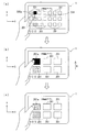
図12(a),(b),(c)は実施形態の一例としての情報処理装置1のタッチパネル200の表示画面における、アイコン表示の遷移を例示する図である。図12(a)はアイコン拡大表示前の状態を、図12(b)はアイコン拡大後の状態を、図12(c)は図12(b)の状態においてX軸方向−側に加速が検知された状態を、それぞれ示す。
A display control method of the
FIGS. 12A, 12 </ b> B, and 12 </ b> C are diagrams illustrating the transition of icon display on the display screen of the
すなわち、図12(a)に例示するように、タッチパネル200に7個のアイコン201が水平方向に並べて表示されている情報処理装置1を、利用者がその左手で保持する。この際、7つのアイコン201の内、左端側の破線で示す2つのアイコン201に利用者の左手の親指(操作体)がかかる。
接触センサ113がタッチパネル200上におけるこの利用者の左手親指を検知し、接触形状判断処理部23が、タッチパネル200における接触を認識した認識点の集合体の輪郭形状をタッチパネル200の接触物の形状(接触物形状)と認識する。接触形状判断処理部23は、この認識した接触物形状を、予め形状登録部24に登録されている利用者の指の規定形状(形状マスタ)と比較する。そして、これらの形状が一致もしくは略一致した場合に、入力制御処理部41にその旨を通知する。
That is, as illustrated in FIG. 12A, the user holds the
The
入力制御処理部41は、接触物形状の規定形状点P1と重合するもしくは最も近い位置にあるアイコン201を被選択アイコン201aとする。図12(a)に示す例においては、タッチパネル200上に水平方向に並ぶ7個のアイコン201の内、左端から3つ目の黒く塗りつぶされたアイコン201が被選択アイコン201aである。
入力制御処理部41は、表示操作処理部30のアイコン配置処理部31に対して、接触アイコン201及び被選択アイコン201aを通知する。
The input
The input
アイコン配置処理部31は、図12(b)に示すような、一部のアイコン201を拡大表示させたアイコン拡大表示後画面をタッチパネル200の表示画面に表示させる。
すなわち、アイコン配置処理部31は、タッチパネル200の表示画面上の複数のアイコン201のうち被選択アイコン201a以外の接触アイコン201を、タッチパネル200から非表示にする。又、アイコン配置処理部31は、タッチパネル200の表示画面上において、非表示にした接触アイコン201の元領域も用いて、被選択アイコン201aを含む複数のアイコン201を拡大表示させる。
The icon arrangement processing unit 31 causes the display screen of the
That is, the icon arrangement processing unit 31 hides from the
また、アイコン配置処理部31は、拡大表示した被選択アイコン201aを接触物形状の下に配置することで、この被選択アイコン201aを選択された状態(決定待機状態)にする。
次に、利用者が、情報処理装置1をその左手で保持したまま、例えば、図12(b)中矢印Aで示すように水平方向(X軸方向−側)に瞬間的に移動させると、加速度情報処理部21がこの情報処理装置1の矢印A方向への加速を検知し、アイコン配置処理部31にその旨及び加速方向を通知する。
In addition, the icon arrangement processing unit 31 places the selected
Next, when the user instantaneously moves in the horizontal direction (X-axis direction-side) as indicated by an arrow A in FIG. 12B while holding the
アイコン配置処理部31は、検知された加速方向に応じて、図12(c)に示すように、タッチパネル200の表示画面上のアイコン201を1つずつ加速方向に沿ってずらして配置する。
この際、タッチパネル200の表示画面上のアイコン201を1つずつ加速方向にずらすことにより、被選択アイコン201aであったアイコン201がタッチパネル200上から消える。その代わりに、タッチパネル200上に表示されているアイコン201の加速方向とは反対側位置には、図12(a)において当該アイコン201に隣接しているアイコン201が新たに拡大表示される。
According to the detected acceleration direction, the icon arrangement processing unit 31 arranges the
At this time, by shifting the
また、タッチパネル200上から消えた先の被選択アイコン201aの右側(加速方向とは反対側)に位置しているアイコン201が、新たな被選択アイコン201aとなり、タッチパネル200上において利用者の左手親指(操作体)の下に配置され、決定待機状態とする。
図12(a),(b),(c)に示した例においては、本情報処理装置1をX軸方向(水平方向)に沿って移動させる場合のアイコン表示の遷移を示したが、これに限定されるものではなく、種々変形して実施することができる。
Further, the
In the example shown in FIGS. 12A, 12 </ b> B, and 12 </ b> C, the transition of icon display when the
以下に、図13(a),(b),(c)を参照しながら、本情報処理装置1をY軸方向(上下方向)に沿って移動させる場合のアイコン表示の遷移を説明する。
図13(a),(b),(c)は実施形態の一例としての情報処理装置1のタッチパネル200の表示画面における、アイコン表示の遷移を例示する図である。図13(a)はアイコン拡大表示前の状態を、図13(b)はアイコン拡大後の状態を、図13(c)は図13(b)の状態においてY軸方向+側に加速が検知された状態を、それぞれ示す。
Hereinafter, transition of icon display when the
FIGS. 13A, 13 </ b> B, and 13 </ b> C are diagrams illustrating the transition of icon display on the display screen of the
図13(a)に示す例においては、タッチパネル200に、3行×7列の21個のアイコン201が並べて表示されている。
利用者がこの情報処理装置1をその左手で保持する。これにより、21個のアイコン201の内の左端側の破線で示す3つのアイコン201に利用者の左手の親指(操作体)がかかる。すなわち、これらの破線で示す3つのアイコン201が接触アイコン201である。
In the example shown in FIG. 13A, 21
A user holds the
接触センサ113がタッチパネル200上におけるこの利用者の左手親指を検知し、接触形状判断処理部23が、タッチパネル200における接触を認識した認識点の集合体の輪郭形状をタッチパネル200の接触物の形状(接触物形状)と認識する。接触形状判断処理部23は、この認識した接触物形状を、予め形状登録部24に登録されている利用者の規定形状(形状マスタ)と比較する。そして、これらの形状が一致もしくは略一致した場合に、入力制御処理部41にその旨を通知する。
The
入力制御処理部41は、接触物形状の規定形状点P1と重合するもしくは最も近い位置にあるアイコン201を被選択アイコン201aとする。図13(a)に示す例においては、タッチパネル200の左上方に位置する黒く塗りつぶされたアイコン201が被選択アイコン201aである。
入力制御処理部41は、表示操作処理部30のアイコン配置処理部31に対して、接触アイコン201及び被選択アイコン201aを通知する。
The input
The input
アイコン配置処理部31は、図13(b)に示すような、一部のアイコン201を拡大表示させたアイコン拡大表示後画面をタッチパネル200の表示画面に表示させる。図13(b)に示す例においては、タッチパネル200の表示画面上に、被選択アイコン201aを含む6つのアイコン201が拡大表示されている。
すなわち、アイコン配置処理部31は、例えば図12(a)に示した状態から、被選択アイコン201aと、この被選択アイコン201aの周囲のアイコン201だけを拡大表示させ、これら以外のアイコン201を非表示にする。
The icon arrangement processing unit 31 causes the display screen of the
That is, the icon arrangement processing unit 31 enlarges and displays only the selected
アイコン配置処理部31は、拡大表示した被選択アイコン201aを操作体と重合する位置に配置するとともに、この被選択アイコン201aの周囲のアイコン201のうち、拡大表示した状態でタッチパネル200の表示画面内に表示可能なアイコン201だけをタッチパネル200に表示させる。
この際、接触アイコン201の内、被選択アイコン201aと同じ行もしくは同じ列に並ぶもの以外の接触アイコン201は非表示とする。アイコン配置処理部31は、タッチパネル200の表示画面上において、非表示にした接触アイコン201の元領域を用いて、被選択アイコン201aを含む他のアイコン201を拡大表示させるのである。
The icon arrangement processing unit 31 arranges the selected
At this time,
アイコン配置処理部31は、タッチパネル200上の操作体の位置に合わせて被選択アイコン201aを配置し、この被選択アイコン201aを基準として、拡大表示前画面と各アイコン201の並び、すなわち、X軸方向及びY軸方向に並ぶ複数のアイコン201の相互の位置関係は変えずに、図13(a)に示した並びと同一に配置する。
また、アイコン配置処理部31は、拡大表示した被選択アイコン201aを接触物形状の下に配置することで、この被選択アイコン201aを選択された状態(決定待機状態)にする。
The icon arrangement processing unit 31 arranges the selected
In addition, the icon arrangement processing unit 31 places the selected
これにより、アイコン配置処理部31が表示変更を行なうことにより、あたかもタッチパネル200上において、被選択アイコン201aとその周囲のアイコン201(接触アイコン201を除く)とを含む領域が拡大されたように表示される。
次に、利用者が、情報処理装置1をその左手で保持したまま、例えば、図13(b)中矢印Bで示すように上方向(Y軸方向+側)に瞬間的に移動させると、加速度情報処理部21がこの情報処理装置1の矢印B方向への加速を検知し、アイコン配置処理部31にその旨及び加速方向を通知する。
As a result, the icon arrangement processing unit 31 changes the display, so that the area including the selected
Next, when the user holds the
アイコン配置処理部31は、検知された加速方向に応じて、図13(c)に示すように、タッチパネル200の表示画面上の各アイコン201を1つずつ加速方向にずらして配置する。
この際、タッチパネル200の表示画面上の各アイコン201を1つずつ加速方向にずらすことにより、被選択アイコン201aであったアイコン201及び当該アイコン201と同行に並ぶアイコン201がタッチパネル200上から消える。その代わりに、タッチパネル200上に表示されているアイコン201の加速方向とは反対側位置には、図13(a)において当該アイコン201に隣接しているアイコン201及び当該アイコン201と同行に並ぶアイコン201が新たに拡大表示される。
The icon arrangement processing unit 31 arranges each
At this time, by shifting each
また、タッチパネル200上から消えた先の被選択アイコン201aの、前記加速方向とは反対側(図中下側)に位置しているアイコン201が、新たな被選択アイコン201aとなり、タッチパネル200上において利用者の左手親指(操作体)の下に配置され、決定待機状態とする。
次に、実施形態の一例としての情報処理装置1の情報処理判断部20の処理を、図14に示すフローチャート(ステップA1〜A6)に従って説明する。
In addition, the
Next, processing of the information
利用者の操作体(親指)が本情報処理装置1のタッチパネル200に接触すると、接触センサ113が検知し、単ポイントあるいは複数ポイントの接触検知結果を情報処理判断部20に通知する(ステップA1)。
情報処理判断部20において、接触検知結果処理部22が接触センサ113からの接触検知結果を受信して処理を開始する。接触検知結果処理部22は接触形状判断処理部23に接触検知結果を通知する。
When the user's operating tool (thumb) comes into contact with the
In the information
ステップA2において、接触形状判断処理部23は、通知された接触検知結果に基づき、接触物形状として判別可能であるか否かを判断する。この判断の結果、接触形状を判別できない場合には(ステップA2のNOルート参照)、処理を終了する。例えば、接触が1点である場合には接触物形状として判別できないため本処理は終了する。
接触検知結果が接触物形状として判別可能である場合には(ステップA2のYESルート参照)、ステップA3において、接触形状判断処理部23は、タッチパネル200における接触を認識した認識点の集合体の輪郭形状を接触物形状として認識する。
In step A2, the contact shape determination processing unit 23 determines whether or not the contact shape can be determined based on the notified contact detection result. If the contact shape cannot be determined as a result of this determination (see the NO route in step A2), the process ends. For example, when the number of contacts is one point, this processing ends because it cannot be determined as a contact object shape.
When the contact detection result can be determined as the contact object shape (see YES route in step A2), in step A3, the contact shape determination processing unit 23 outlines the collection of recognition points that recognized the contact on the
ステップA4において、接触形状判断処理部23は、認識した接触物形状と、形状登録部24に登録されている規定形状とを比較して、接触物形状が登録されている形状であるか判断する。接触物形状が登録されている形状でない場合には(ステップA4のNOルート参照)、処理を終了する。
接触物形状が登録されている形状である場合には(ステップA4のYESルート参照)、ステップA5において、接触形状判断処理部23は、入力制御処理部41へ規定形状接触、すなわち、規定された親指等の操作体による接触(操作体接触)であることを通知する。
In step A4, the contact shape determination processing unit 23 compares the recognized contact object shape with the specified shape registered in the shape registration unit 24, and determines whether the contact object shape is a registered shape. . If the contact object shape is not a registered shape (see NO route in step A4), the process ends.
When the contact object shape is a registered shape (see YES route in step A4), in step A5, the contact shape determination processing unit 23 contacts the input
ステップA6において、入力制御処理部41は、表示操作処理部30に対して、接触形状判断処理部23から受信した規定形状に関する情報を表示操作処理部30に通知する。すなわち、規定形状の形状や、検知された接触物位置に規定形状を配置した場合の当該規定形状の座標情報や規定形状点P1の情報を表示操作処理部30に通知して、処理を終了する。その後、図15に示す表示操作処理部30による処理に移行する。
In step A <b> 6, the input
次に、実施形態の一例としての情報処理装置1の表示操作処理部が処理する流れを、図15に示すフローチャート(ステップB1〜B10)に従って説明する。
ステップB1において、表示操作処理部30は、入力制御処理部41から通知された規定形状の座標と、タッチパネル200の表示画面に表示されている各アイコン201の座標範囲とを認識する。
Next, a flow performed by the display operation processing unit of the
In step B <b> 1, the display
ステップB2において、表示操作処理部30は、規定形状とアイコン201とが接触しているか否かを確認する。すなわち、表示操作処理部30は、規定形状が確認された形状範囲(規定形状座標範囲)内にアイコン201が含まれるか(かかっているか)否かを確認する。
規定形状とアイコン201とが接触していない場合には(ステップB2のNOルート参照)、ステップB3において、表示操作処理部30は、規定形状の規定形状点P1に最も近いアイコン201を、被選択アイコン201aとして認識する。
In step B <b> 2, the display
When the prescribed shape and the
一方、規定形状と1つ以上のアイコン201が接触している場合には(ステップB2のYESルート参照)、ステップB4において、表示操作処理部30は、この規定形状に接触しているアイコン201から被選択アイコン201aを選択して認識する。
すなわち、規定形状と複数のアイコン201とが接触している場合には、表示操作処理部30は、規定形状に接触しているこれらのアイコン201の中から、規定形状点P1に最も近いアイコン201を被選択アイコン201aとして認識する。この際、規定形状点P1と重合しているアイコン201がある場合には、この重合しているアイコン201を被選択アイコン201aとする。又、規定形状と1つのアイコン201とが接触している場合には、表示操作処理部30は、この規定形状に接触しているアイコン201を被選択アイコン201aとして認識する。
On the other hand, when the prescribed shape is in contact with one or more icons 201 (see YES route in step B2), in step B4, the display
That is, when the specified shape and the plurality of
なお、規定形状に接触しているアイコン201が1つしかない場合は、そのアイコン201が操作体に接触していることを利用者に明示する何らかの通知制御を行なってもよい。例えば、アイコン201の表示色や形状、サイズ等を変更するような制御を行なってもよく、又、音声や図示しないバイブレータを用いて通知してもよい。
その後、ステップB5において、アイコン配置処理部31は、タッチパネル200の表示画面上から、被選択アイコン201aを除く接触アイコン201を非表示にする。すなわち、規定形状座標範囲に接触する接触アイコン201の内、被選択アイコン201a以外の接触アイコン201を非表示にする。
When there is only one
Thereafter, in step B5, the icon arrangement processing unit 31 hides the
ステップB6において、アイコン配置処理部31は、タッチパネル200の表示画面上において、非表示にした接触アイコン201の元領域を用いて、接触アイコン201を除く、被選択アイコン201aを含む他のアイコン201を拡大表示させる。ステップB5において接触アイコン201を非表示にすることにより、タッチパネル200の表示画面上において、他のアイコン201を拡大表示するためのスペースを確保することができる。すなわち、この非表示にした接触アイコン201があったスペースを用いてアイコン201を拡大することができるのである。
In step B <b> 6, the icon arrangement processing unit 31 uses the original area of the
また、アイコン配置処理部31は、被選択アイコン201aを操作体と重合する位置に配置する。これにより、この被選択アイコン201aを決定待機状態にする。
ステップB7において、入力制御処理部41は、決定待機状態の被選択アイコン201aについて、当該被選択アイコン201から操作体が離れたか(非接触状態となったか)否かを検知(非接触検知)する。
The icon arrangement processing unit 31 arranges the selected
In step B <b> 7, the input
被選択アイコン201から操作体が離れたことが検知されない場合には(ステップB7のNOルート参照)、ステップB8において、加速度情報処理部21が本情報処理装置1の加速を検知(加速度検知)したか否かを判断する。
加速度情報処理部21が加速度センサ112からの信号に基づき加速を検知した場合には(ステップB8のYESルート参照)、ステップB9において、アイコン配置処理部31が、その加速方向に応じてタッチパネル200の表示画面上でアイコン201の配置を変更する。すなわち、アイコン配置処理部31は、タッチパネル200の表示画面に拡大表示されている各アイコン201を、検出された加速度方向に1つずつずらして配置変更することにより、各アイコン201を加速度方向に移動させたように表示する。又、アイコン配置処理部31は、配置変更前に被選択アイコン201aに加速方向とは反対側に隣接していたアイコン201を操作体の下に配置する。これにより、このアイコン201を新たな被選択アイコン201aとして、当該被選択アイコン201aを選択された状態(決定待機状態)にする。
When it is not detected that the operating body has moved away from the selected icon 201 (see NO route in step B7), in step B8, the acceleration information processing unit 21 detects acceleration of the information processing apparatus 1 (acceleration detection). Determine whether or not.
When the acceleration information processing unit 21 detects acceleration based on a signal from the acceleration sensor 112 (see YES route in step B8), in step B9, the icon arrangement processing unit 31 determines whether or not the
すなわち、操作体が被選択アイコン201aに接触した状態で、加速度情報処理部21により加速が検出されると、アイコン配置処理部31が、被選択アイコン201aに加速方向とは反対側に隣接する次のアイコン201を、次の被選択アイコン201aと設定する。そして、アイコン配置処理部31は、この次の被選択アイコン201aを規定形状座標範囲に位置するようにアイコン配置を変更する。
That is, when acceleration is detected by the acceleration information processing unit 21 in a state where the operating tool is in contact with the selected
その後、処理はステップB7に戻る。又、加速度情報処理部21が加速度センサ112からの信号に基づき加速を検知しない場合にも(ステップB8のNOルート参照)、処理はステップB7に戻る。
ステップB7において、入力制御処理部41は、被選択アイコン201から操作体が離れたことを検知した場合には(ステップB7のYESルート参照)、ソフト起動制御部32に通知を行なう。アイコン201の入力の決定が行なわれた旨の通知を入力制御処理部41から受信したソフト起動制御部32は、ステップB10において、当該アイコン201に対応付けられたプログラム(アイコンソフト)を起動して、処理を終了する。すなわち、このアイコン201に対応付けられたプログラムの起動をもって、ステップB5,B6,B9において行なわれたアイコン201のサイズ変更や配置変更は解除され、通常の表示、操作へ戻る。
Thereafter, the process returns to step B7. Also, when the acceleration information processing unit 21 does not detect acceleration based on the signal from the acceleration sensor 112 (see NO route in step B8), the process returns to step B7.
In step B <b> 7, when the input
このように実施形態の一例としての情報処理装置1によれば、タッチパネル200の表示画面において、利用者の指等の操作体により同時に複数のアイコン201が選択された場合に、被選択アイコン201aと、この被選択アイコン201aの周囲の1以上のアイコン201とを拡大表示する。これにより、利用者がアイコン201を選択し易くなり、アイコン201の誤選択を抑止することができる。
As described above, according to the
この際、操作体により選択された複数のアイコン201の内、被選択アイコン201a以外の接触アイコン201を非表示にすることにより、この非表示にした接触アイコン201の元領域を用いて、被選択アイコン201aを含む他のアイコン201を拡大表示させるための領域を確保することができる。
また、この拡大表示後画面においては、この被選択アイコン201aを基準として、拡大表示前画面と各アイコン201の並び、すなわち、X軸方向及びY軸方向に並ぶ複数のアイコン201の相互の位置関係は変えずに同一の並びとなるように各アイコン201を配置する。すなわち、拡大表示後画面と拡大表示前画面との間で、アイコン配列デザインを変えない。これにより、アイコン配列を機器のデザインとするなら、そのデザインを変更することがなく、統一感等を損なうことがない。
At this time, the
Further, in this post-enlargement display screen, with the selected
さらに、アイコン配置処理部31が、拡大表示された被選択アイコン201aを、タッチパネル200の表示画面上において、利用者の指(操作体)の下に配置させ、決定待機状態とする。これにより、利用者が操作体を被選択アイコン201aから離すだけで当該被選択アイコン201aの入力を決定することができ、アイコン201の決定入力を容易且つ正確に行なうことができ利便性が高い。
Further, the icon arrangement processing unit 31 arranges the enlarged selected
また、操作体が被選択アイコン201aに接触し拡大表示誤画面が表示された状態で、利用者が本情報処理装置1に対して加速度を与る操作を行なうと、加速度情報処理部21が加速を検出し、アイコン配置処理部31が検出された加速度方向にアイコン201を1つずつずらして配置変更する。
これにより、利用者は本情報処理装置1を保持したまま、すなわち、タッチパネル200から指を離すことなく、被選択アイコン201aを変更することができ利便性が高い。特に、利用者が本情報処理装置1に対して加速度を付与した方向に沿って、タッチパネル200上において各アイコン201を1つずつ移動させることで、直感的に被選択アイコン201a等の切り替え操作を行なうことができる。
In addition, when the user touches the selected
Accordingly, the user can change the selected
また、接触形状判断処理部23が、接触検知結果処理部22から通知される座標情報に基づき、タッチパネル200における接触物形状を認識し、この認識した接触物形状を形状登録部24に登録されている形状情報と比較する。そして、この比較の結果、形状情報と一致した場合に、規定情報に含まれる規定形状点P1を用いて、タッチパネル200の表示画面上の複数のアイコン201の中から、被選択アイコン201aを選択することを特徴とする。
Further, the contact shape determination processing unit 23 recognizes the contact object shape on the
これにより、利用者の指等の操作体に合った被選択アイコン201aを効率的に選択することができ利便性が高い。
本情報処理装置1によれば、本装置を特殊な持ち型や姿勢で操作することなく、一般的操作である片手で持った状態で、アイコン201の選択・決定を行なう際に、誤動作の発生を抑止することができる。又、従来手法と同様に、個々のアイコン201を操作体により1つずつ選択・決定することもでき、従来手法の操作性を大きく損ねることもなく利便性が高い。
Thereby, the selected
According to the
そして、開示の技術は上述した実施形態に限定されるものではなく、本実施形態の趣旨を逸脱しない範囲で種々変形して実施することができる。
上述した実施形態においては、図12(a)〜(c)や図13(a)〜(c)に示したような、X軸方向もしくはY軸方向に沿って本情報処理装置1に加速度を与え、この加速方向に沿ってアイコン201を移動表示させる例を示しているが、これに限定されるものではない。
The disclosed technology is not limited to the above-described embodiment, and various modifications can be made without departing from the spirit of the present embodiment.
In the embodiment described above, acceleration is applied to the
例えば、図13(a)に示すような、タッチパネル200にX軸方向及びY軸方向にかけて複数のアイコン201がマトリクス状に並べて表示されている場合において、本情報処理装置1に斜め方向に加速度を加えてもよい。このような場合、すなわちX軸方向及びY軸方向の両方にかかる方向に加速度が付与された場合に、タッチパネル200上において、この加速方向に沿って、斜め方向にアイコン201を移動表示させてもよく、種々変形して実施することができる。
For example, as shown in FIG. 13A, when a plurality of
また、上述した開示により本実施形態を当業者によって実施・製造することが可能である。
以上の実施形態に関し、更に以下の付記を開示する。
(付記1)
複数の被選択要素を表示画面に表示するタッチパネルと、
前記表示画面における接触物形状を認識する認識部と、
前記複数の被選択要素のうち前記接触物形状によって隠される前記被選択要素を非表示にする非表示処理部と、
非表示にした前記被選択要素の元領域を用いて、前記複数の被選択要素のうち前記非表示にした被選択要素とは異なる被選択要素を拡大表示する拡大表示部と
を備えることを特徴とする、入力装置。
Further, according to the above-described disclosure, this embodiment can be implemented and manufactured by those skilled in the art.
Regarding the above embodiment, the following additional notes are disclosed.
(Appendix 1)
A touch panel for displaying a plurality of selected elements on the display screen;
A recognition unit for recognizing a contact object shape on the display screen;
A non-display processing unit for hiding the selected element hidden by the contact object shape among the plurality of selected elements;
An enlarged display unit that enlarges and displays a selected element different from the hidden selected element among the plurality of selected elements, using an original area of the hidden selected element; An input device.
(付記2)
前記接触物形状に基づき、前記表示画面上の前記複数の被選択要素の中から選択候補要素を選択する要素選択部を備え、
前記拡大表示部が、前記選択候補要素を拡大表示することを特徴とする、付記1記載の入力装置。
(Appendix 2)
An element selection unit that selects a selection candidate element from the plurality of selected elements on the display screen based on the contact object shape;
The input device according to
(付記3)
前記要素選択部が、
前記表示画面における接触物形状に基づき、記憶装置に予め記憶された形状マスタから読み出した基準位置情報を用いて、前記表示画面上の前記複数の被選択要素の中から、前記基準位置情報が示す位置に最近接する被選択要素を前記選択候補要素として選択することを特徴とする、付記2記載の入力装置。
(Appendix 3)
The element selection unit is
Based on the contact object shape on the display screen, the reference position information indicates from among the plurality of selected elements on the display screen using reference position information read from a shape master stored in advance in a storage device. The input device according to appendix 2, wherein a selected element closest to a position is selected as the selection candidate element.
(付記4)
前記拡大表示部により拡大表示された前記被選択要素を前記接触物形状の下に配置することで決定待機状態にする配置処理部を備えることを特徴とする、付記1〜付記3のいずれか1項に記載の入力装置。
(付記5)
当該入力装置に加えられた加速方向を検知する加速方向検知部を備え、
前記配置処理部が、前記加速方向に沿って前記表示画面上で被選択要素を移動させることを特徴とする、付記4記載の入力装置。
(Appendix 4)
Any one of the
(Appendix 5)
Provided with an acceleration direction detector for detecting the acceleration direction applied to the input device,
The input device according to appendix 4, wherein the arrangement processing unit moves a selected element on the display screen along the acceleration direction.
(付記6)
タッチパネルの表示画面おける複数の被選択要素の表示制御方法であって、
前記表示画面における接触物形状を認識する処理と、
前記複数の被選択要素のうち前記接触物形状によって隠される前記被選択要素を非表示にする処理と、
非表示にした前記被選択要素の元領域を用いて、前記複数の被選択要素のうち前記非表示にした被選択要素とは異なる被選択要素を拡大表示する処理と
を備えることを特徴とする、表示制御方法。
(Appendix 6)
A display control method for a plurality of selected elements on a display screen of a touch panel,
Processing for recognizing a contact object shape on the display screen;
A process of hiding the selected element hidden by the contact object shape among the plurality of selected elements;
And a process of enlarging and displaying a selected element different from the non-selected selected element among the plurality of selected elements using an original area of the non-displayed selected element. , Display control method.
(付記7)
前記接触物形状に基づき、前記表示画面上の前記複数の被選択要素の中から選択候補要素を選択する処理を備え、
前記選択候補要素を拡大表示することを特徴とする、付記6記載の表示制御方法。
(付記8)
前記表示画面における接触物形状に基づき、記憶装置に予め記憶された形状マスタから読み出した基準位置情報を用いて、前記表示画面上の前記複数の被選択要素の中から、前記基準位置情報が示す位置に最近接する被選択要素を前記選択候補要素として選択することを特徴とする、付記7記載の表示制御方法。
(Appendix 7)
A process of selecting a selection candidate element from the plurality of selected elements on the display screen based on the contact object shape,
The display control method according to appendix 6, wherein the selection candidate element is enlarged and displayed.
(Appendix 8)
Based on the contact object shape on the display screen, the reference position information indicates from among the plurality of selected elements on the display screen using reference position information read from a shape master stored in advance in a storage device. The display control method according to appendix 7, wherein a selected element closest to a position is selected as the selection candidate element.
(付記9)
拡大表示された前記被選択要素を前記接触物形状の下に配置することで決定待機状態にする処理を備えることを特徴とする、付記6〜付記8のいずれか1項に記載の表示制御方法。
(付記10)
当該入力装置に加えられた加速方向を検知する処理を備え、
前記加速方向に沿って前記表示画面上で被選択要素を移動させることを特徴とする、付記9記載の表示制御方法。
(Appendix 9)
The display control method according to any one of appendix 6 to appendix 8, further comprising a process of placing the selected element displayed in an enlarged manner under the contact object shape so as to be in a determination standby state. .
(Appendix 10)
A process for detecting the acceleration direction applied to the input device;
The display control method according to appendix 9, wherein the selected element is moved on the display screen along the acceleration direction.
(付記11)
タッチパネルの表示画面における接触物形状を認識し、
前記表示画面に表示された複数の被選択要素のうち前記接触物形状によって隠される前記被選択要素を非表示にし、
非表示にした前記被選択要素の元領域を用いて、前記複数の被選択要素のうち前記非表示にした被選択要素とは異なる被選択要素を拡大表示する
処理をコンピュータに実行させることを特徴とするプログラム。
(Appendix 11)
Recognize the contact object shape on the display screen of the touch panel,
Hide the selected element hidden by the contact object shape among the plurality of selected elements displayed on the display screen,
Using the original area of the non-displayed selected element, causing a computer to execute a process of enlarging and displaying a selected element different from the non-selected selected element among the plurality of selected elements. Program.
(付記12)
前記接触物形状に基づき、前記表示画面上の前記複数の被選択要素の中から選択候補要素を選択し、
前記選択候補要素を拡大表示する
処理を前記コンピュータに実行させることを特徴とする、付記11記載のプログラム。
(Appendix 12)
Based on the contact object shape, select a selection candidate element from the plurality of selected elements on the display screen,
The program according to appendix 11, wherein the computer is caused to execute a process of enlarging and displaying the selection candidate element.
(付記13)
前記表示画面における接触物形状に基づき、記憶装置に予め記憶された形状マスタから読み出した基準位置情報を用いて、前記表示画面上の前記複数の被選択要素の中から、前記基準位置情報が示す位置に最近接する被選択要素を前記選択候補要素として選択する
処理を前記コンピュータに実行させることを特徴とする、付記12記載のプログラム。
(Appendix 13)
Based on the contact object shape on the display screen, the reference position information indicates from among the plurality of selected elements on the display screen using reference position information read from a shape master stored in advance in a storage device. The program according to appendix 12, wherein the computer is caused to execute a process of selecting a selected element closest to a position as the selection candidate element.
(付記14)
拡大表示された前記被選択要素を前記接触物形状の下に配置することで決定待機状態にする
処理を前記コンピュータに実行させることを特徴とする、付記11〜付記13のいずれか1項に記載のプログラム。
(Appendix 14)
14. The method according to any one of appendices 11 to 13, wherein the computer is caused to execute a process of placing the selected element displayed in an enlarged manner under the contact object shape so as to enter a determination standby state. Program.
(付記15)
当該入力装置に加えられた加速方向を検知し、
前記加速方向に沿って前記表示画面上で被選択要素を移動させる
処理を前記コンピュータに実行させることを特徴とする、付記14記載のプログラム。
(付記16)
タッチパネルの表示画面における接触物形状を認識する認識部と、
前記複数の被選択要素のうち前記接触物形状によって隠される前記被選択要素を非表示にする非表示処理部と、
非表示にした前記被選択要素の元領域を用いて、前記複数の被選択要素のうち前記非表示にした被選択要素とは異なる被選択要素を拡大表示する拡大表示部と
を備えることを特徴とする、集積回路装置。
(Appendix 15)
Detect the acceleration direction applied to the input device,
15. The program according to appendix 14, wherein the computer is caused to execute a process of moving a selected element on the display screen along the acceleration direction.
(Appendix 16)
A recognition unit for recognizing a contact object shape on the display screen of the touch panel;
A non-display processing unit for hiding the selected element hidden by the contact object shape among the plurality of selected elements;
An enlarged display unit that enlarges and displays a selected element different from the hidden selected element among the plurality of selected elements, using an original area of the hidden selected element; An integrated circuit device.
(付記17)
前記接触物形状に基づき、前記表示画面上の前記複数の被選択要素の中から選択候補要素を選択する要素選択部を備え、
前記拡大表示部が、前記選択候補要素を拡大表示することを特徴とする、付記16記載の集積回路装置。
(Appendix 17)
An element selection unit that selects a selection candidate element from the plurality of selected elements on the display screen based on the contact object shape;
The integrated circuit device according to supplementary note 16, wherein the enlarged display unit enlarges and displays the selection candidate element.
(付記18)
前記要素選択部が、
前記表示画面における接触物形状に基づき、記憶装置に予め記憶された形状マスタ(規定形状)から読み出した基準位置情報を用いて、前記表示画面上の前記複数の被選択要素の中から、前記基準位置情報が示す位置に最近接する被選択要素を前記選択候補要素として選択することを特徴とする、付記17記載の集積回路装置。
(Appendix 18)
The element selection unit is
Based on the contact object shape on the display screen, the reference position information read from the shape master (prescribed shape) stored in the storage device in advance is used to select the reference from the plurality of selected elements on the display screen. The integrated circuit device according to appendix 17, wherein a selected element closest to a position indicated by position information is selected as the selection candidate element.
(付記19)
前記拡大表示部により拡大表示された前記被選択要素を前記接触物形状の下に配置することで決定待機状態にする配置処理部を備えることを特徴とする、付記16〜付記18のいずれか1項に記載の集積回路装置。
(付記20)
当該入力装置に加えられた加速方向を検知する加速方向検知部を備え、
前記配置処理部が、前記加速方向に沿って前記表示画面上で被選択要素を移動させることを特徴とする、付記19記載の集積回路装置。
(Appendix 19)
Any one of Supplementary Note 16 to Supplementary Note 18, further comprising an arrangement processing unit configured to place the selected element enlarged and displayed by the enlarged display unit below the contact object shape to make a determination standby state. An integrated circuit device according to item.
(Appendix 20)
Provided with an acceleration direction detector for detecting the acceleration direction applied to the input device,
20. The integrated circuit device according to appendix 19, wherein the placement processing unit moves a selected element on the display screen along the acceleration direction.
1 情報処理装置
10 センサ部
20 情報処理判断部
21 加速度情報処理部
22 接触検知結果処理部
23 接触形状判断処理部
24 形状登録部
30 表示操作処理部
31 アイコン配置処理部
32 ソフト起動制御部
41 入力制御処理部
42 プッシュボタン処理部
101 WiFi通信モジュール
102 3G/LTE通信モジュール
103 ストレージ
104 プッシュボタン
105 カメラ
106 液晶ディスプレイ
107 グラフィックアクセラレータ
108 オーディオモジュール
109 マイク
110 GPSモジュール
111 ジャイロセンサ
112 加速度センサ
113 接触センサ
114 タイマ
115 CPU
117 チップセット
200 タッチパネル
201 アイコン
201a 被選択アイコン
401 表面
402 フィルム面
403 ガラス面
403a 透明電極膜
P1 規定形状点
DESCRIPTION OF
117 chip set 200
402
403a Transparent electrode film P1 Specified shape point
Claims (8)
前記表示画面における接触物形状を認識する認識部と、
前記複数の被選択要素のうち前記接触物形状によって隠される前記被選択要素を非表示にする非表示処理部と、
非表示にした前記被選択要素の元領域を用いて、前記複数の被選択要素のうち前記非表示にした被選択要素とは異なる被選択要素を拡大表示する拡大表示部と
を備えることを特徴とする、入力装置。 A touch panel for displaying a plurality of selected elements on the display screen;
A recognition unit for recognizing a contact object shape on the display screen;
A non-display processing unit for hiding the selected element hidden by the contact object shape among the plurality of selected elements;
An enlarged display unit that enlarges and displays a selected element different from the hidden selected element among the plurality of selected elements, using an original area of the hidden selected element; An input device.
前記拡大表示部が、前記選択候補要素を拡大表示することを特徴とする、請求項1記載の入力装置。 An element selection unit that selects a selection candidate element from the plurality of selected elements on the display screen based on the contact object shape;
The input device according to claim 1, wherein the enlargement display unit enlarges and displays the selection candidate element.
前記表示画面における接触物形状に基づき、記憶装置に予め記憶された形状マスタから読み出した基準位置情報を用いて、前記表示画面上の前記複数の被選択要素の中から、前記基準位置情報が示す位置に最近接する被選択要素を前記選択候補要素として選択することを特徴とする、請求項2記載の入力装置。 The element selection unit is
Based on the contact object shape on the display screen, the reference position information indicates from among the plurality of selected elements on the display screen using reference position information read from a shape master stored in advance in a storage device. The input device according to claim 2, wherein the selected element closest to the position is selected as the selection candidate element.
前記配置処理部が、前記加速方向に沿って前記表示画面上で被選択要素を移動させることを特徴とする、請求項4記載の入力装置。 Provided with an acceleration direction detector for detecting the acceleration direction applied to the input device,
The input device according to claim 4, wherein the placement processing unit moves the selected element on the display screen along the acceleration direction.
前記表示画面における接触物形状を認識する処理と、
前記複数の被選択要素のうち前記接触物形状によって隠される前記被選択要素を非表示にする処理と、
非表示にした前記被選択要素の元領域を用いて、前記複数の被選択要素のうち前記非表示にした被選択要素とは異なる被選択要素を拡大表示する処理と
を備えることを特徴とする、表示制御方法。 A display control method for a plurality of selected elements on a display screen of a touch panel,
Processing for recognizing a contact object shape on the display screen;
A process of hiding the selected element hidden by the contact object shape among the plurality of selected elements;
And a process of enlarging and displaying a selected element different from the non-selected selected element among the plurality of selected elements using an original area of the non-displayed selected element. , Display control method.
前記表示画面に表示された複数の被選択要素のうち前記接触物形状によって隠される前記被選択要素を非表示にし、
非表示にした前記被選択要素の元領域を用いて、前記複数の被選択要素のうち前記非表示にした被選択要素とは異なる被選択要素を拡大表示する
処理をコンピュータに実行させることを特徴とするプログラム。 Recognize the contact object shape on the display screen of the touch panel,
Hide the selected element hidden by the contact object shape among the plurality of selected elements displayed on the display screen,
Using the original area of the non-displayed selected element, causing a computer to execute a process of enlarging and displaying a selected element different from the non-selected selected element among the plurality of selected elements. Program.
前記表示画面に表示される複数の被選択要素のうち前記接触物形状によって隠される前記被選択要素を非表示にする非表示処理部と、
非表示にした前記被選択要素の元領域を用いて、前記複数の被選択要素のうち前記非表示にした被選択要素とは異なる被選択要素を拡大表示する拡大表示部と
を備えることを特徴とする、集積回路装置。 A recognition unit for recognizing a contact object shape on the display screen of the touch panel;
A non-display processing unit configured to hide the selected element hidden by the contact object shape among the plurality of selected elements displayed on the display screen ;
An enlarged display unit that enlarges and displays a selected element different from the hidden selected element among the plurality of selected elements, using an original area of the hidden selected element; An integrated circuit device.
Priority Applications (2)
| Application Number | Priority Date | Filing Date | Title |
|---|---|---|---|
| JP2014006999A JP6233040B2 (en) | 2014-01-17 | 2014-01-17 | Input device, display control method, program, and integrated circuit device |
| US14/574,180 US9996215B2 (en) | 2014-01-17 | 2014-12-17 | Input device, display control method, and integrated circuit device |
Applications Claiming Priority (1)
| Application Number | Priority Date | Filing Date | Title |
|---|---|---|---|
| JP2014006999A JP6233040B2 (en) | 2014-01-17 | 2014-01-17 | Input device, display control method, program, and integrated circuit device |
Publications (2)
| Publication Number | Publication Date |
|---|---|
| JP2015135613A JP2015135613A (en) | 2015-07-27 |
| JP6233040B2 true JP6233040B2 (en) | 2017-11-22 |
Family
ID=53544810
Family Applications (1)
| Application Number | Title | Priority Date | Filing Date |
|---|---|---|---|
| JP2014006999A Active JP6233040B2 (en) | 2014-01-17 | 2014-01-17 | Input device, display control method, program, and integrated circuit device |
Country Status (2)
| Country | Link |
|---|---|
| US (1) | US9996215B2 (en) |
| JP (1) | JP6233040B2 (en) |
Families Citing this family (2)
| Publication number | Priority date | Publication date | Assignee | Title |
|---|---|---|---|---|
| US10048829B2 (en) * | 2015-06-26 | 2018-08-14 | Lenovo (Beijing) Co., Ltd. | Method for displaying icons and electronic apparatus |
| US11822743B2 (en) * | 2019-06-12 | 2023-11-21 | Nippon Telegraph And Telephone Corporation | Touch panel information terminal apparatus and information input processing method implemented with dual input devices arranged on two surfaces |
Family Cites Families (13)
| Publication number | Priority date | Publication date | Assignee | Title |
|---|---|---|---|---|
| US6073036A (en) * | 1997-04-28 | 2000-06-06 | Nokia Mobile Phones Limited | Mobile station with touch input having automatic symbol magnification function |
| JP2006331092A (en) | 2005-05-26 | 2006-12-07 | Toshiba Corp | Automatic processor |
| JP5537044B2 (en) | 2008-05-30 | 2014-07-02 | キヤノン株式会社 | Image display apparatus, control method therefor, and computer program |
| JP5356752B2 (en) * | 2008-08-25 | 2013-12-04 | Necカシオモバイルコミュニケーションズ株式会社 | Terminal device and program |
| WO2010029415A2 (en) * | 2008-09-10 | 2010-03-18 | Opera Software Asa | Method and apparatus for providing finger touch layers in a user agent |
| JP5476790B2 (en) | 2009-05-13 | 2014-04-23 | 富士通株式会社 | Electronic device, display method, and display program |
| JP5348689B2 (en) * | 2009-05-22 | 2013-11-20 | Necカシオモバイルコミュニケーションズ株式会社 | Portable terminal device and program |
| JP2011028560A (en) * | 2009-07-27 | 2011-02-10 | Sony Corp | Information processing apparatus, display method, and display program |
| US20130021256A1 (en) * | 2010-03-26 | 2013-01-24 | Nec Corporation | Mobile terminal with touch panel function and input method for same |
| JP5614173B2 (en) * | 2010-08-25 | 2014-10-29 | ソニー株式会社 | Information processing apparatus, information processing method, and program |
| WO2013039544A1 (en) * | 2011-08-10 | 2013-03-21 | Cypress Semiconductor Corporation | Methods and apparatus to detect a presence of a conductive object |
| JP5779064B2 (en) * | 2011-09-28 | 2015-09-16 | 京セラ株式会社 | Apparatus, method, and program |
| KR101991493B1 (en) * | 2012-01-17 | 2019-06-20 | 삼성전자주식회사 | Method for providing touch interface, machine-readable storage medium and portable terminal |
-
2014
- 2014-01-17 JP JP2014006999A patent/JP6233040B2/en active Active
- 2014-12-17 US US14/574,180 patent/US9996215B2/en not_active Expired - Fee Related
Also Published As
| Publication number | Publication date |
|---|---|
| US9996215B2 (en) | 2018-06-12 |
| US20150205486A1 (en) | 2015-07-23 |
| JP2015135613A (en) | 2015-07-27 |
Similar Documents
| Publication | Publication Date | Title |
|---|---|---|
| EP3461291B1 (en) | Implementation of a biometric enrollment user interface | |
| US8749497B2 (en) | Multi-touch shape drawing | |
| EP2808781B1 (en) | Method, storage medium, and electronic device for mirroring screen data | |
| KR102269598B1 (en) | The method to arrange an object according to an content of an wallpaper and apparatus thereof | |
| US9977497B2 (en) | Method for providing haptic effect set by a user in a portable terminal, machine-readable storage medium, and portable terminal | |
| EP2332023B1 (en) | Two-thumb qwerty keyboard | |
| JP5532300B2 (en) | Touch panel device, touch panel control method, program, and recording medium | |
| JP6039343B2 (en) | Electronic device, control method of electronic device, program, storage medium | |
| JP6381032B2 (en) | Electronic device, control method thereof, and program | |
| CN108733303B (en) | Touch input method and apparatus of portable terminal | |
| KR20170062954A (en) | User terminal device and method for display thereof | |
| US20110148774A1 (en) | Handling Tactile Inputs | |
| JP6429886B2 (en) | Touch control system and touch control method | |
| JP2010067135A (en) | Information processor, information processing method and computer program | |
| JP2010140321A (en) | Information processing apparatus, information processing method, and program | |
| KR102381051B1 (en) | Electronic device for displaying keypad and keypad displaying method thereof | |
| JP2008065504A (en) | Touch panel control device and touch panel control method | |
| US9367169B2 (en) | Method, circuit, and system for hover and gesture detection with a touch screen | |
| JP6233040B2 (en) | Input device, display control method, program, and integrated circuit device | |
| JP5820414B2 (en) | Information processing apparatus and information processing method | |
| JP2015038642A (en) | Display processing apparatus and display processing method | |
| JP6331022B2 (en) | Display device, display control method, and display control program | |
| JP5805910B2 (en) | Touch panel system | |
| JP5060651B2 (en) | Display processing apparatus, display control program, and display processing method | |
| JP5855481B2 (en) | Information processing apparatus, control method thereof, and control program thereof |
Legal Events
| Date | Code | Title | Description |
|---|---|---|---|
| A621 | Written request for application examination |
Free format text: JAPANESE INTERMEDIATE CODE: A621 Effective date: 20161004 |
|
| A977 | Report on retrieval |
Free format text: JAPANESE INTERMEDIATE CODE: A971007 Effective date: 20170621 |
|
| A131 | Notification of reasons for refusal |
Free format text: JAPANESE INTERMEDIATE CODE: A131 Effective date: 20170627 |
|
| A521 | Request for written amendment filed |
Free format text: JAPANESE INTERMEDIATE CODE: A523 Effective date: 20170824 |
|
| TRDD | Decision of grant or rejection written | ||
| A01 | Written decision to grant a patent or to grant a registration (utility model) |
Free format text: JAPANESE INTERMEDIATE CODE: A01 Effective date: 20170926 |
|
| A61 | First payment of annual fees (during grant procedure) |
Free format text: JAPANESE INTERMEDIATE CODE: A61 Effective date: 20171009 |
|
| R150 | Certificate of patent or registration of utility model |
Ref document number: 6233040 Country of ref document: JP Free format text: JAPANESE INTERMEDIATE CODE: R150 |
|
| S111 | Request for change of ownership or part of ownership |
Free format text: JAPANESE INTERMEDIATE CODE: R313113 |
|
| R350 | Written notification of registration of transfer |
Free format text: JAPANESE INTERMEDIATE CODE: R350 |
|
| R250 | Receipt of annual fees |
Free format text: JAPANESE INTERMEDIATE CODE: R250 |