JP6231341B2 - Mobile communication system - Google Patents
Mobile communication system Download PDFInfo
- Publication number
- JP6231341B2 JP6231341B2 JP2013200657A JP2013200657A JP6231341B2 JP 6231341 B2 JP6231341 B2 JP 6231341B2 JP 2013200657 A JP2013200657 A JP 2013200657A JP 2013200657 A JP2013200657 A JP 2013200657A JP 6231341 B2 JP6231341 B2 JP 6231341B2
- Authority
- JP
- Japan
- Prior art keywords
- base station
- radio base
- enb
- srb1
- srb2
- Prior art date
- Legal status (The legal status is an assumption and is not a legal conclusion. Google has not performed a legal analysis and makes no representation as to the accuracy of the status listed.)
- Expired - Fee Related
Links
Images


Classifications
-
- H—ELECTRICITY
- H04—ELECTRIC COMMUNICATION TECHNIQUE
- H04W—WIRELESS COMMUNICATION NETWORKS
- H04W76/00—Connection management
- H04W76/10—Connection setup
-
- H—ELECTRICITY
- H04—ELECTRIC COMMUNICATION TECHNIQUE
- H04L—TRANSMISSION OF DIGITAL INFORMATION, e.g. TELEGRAPHIC COMMUNICATION
- H04L5/00—Arrangements affording multiple use of the transmission path
- H04L5/0091—Signaling for the administration of the divided path
- H04L5/0096—Indication of changes in allocation
- H04L5/0098—Signalling of the activation or deactivation of component carriers, subcarriers or frequency bands
-
- H—ELECTRICITY
- H04—ELECTRIC COMMUNICATION TECHNIQUE
- H04L—TRANSMISSION OF DIGITAL INFORMATION, e.g. TELEGRAPHIC COMMUNICATION
- H04L5/00—Arrangements affording multiple use of the transmission path
- H04L5/0001—Arrangements for dividing the transmission path
- H04L5/0003—Two-dimensional division
- H04L5/0005—Time-frequency
- H04L5/0007—Time-frequency the frequencies being orthogonal, e.g. OFDM(A), DMT
- H04L5/001—Time-frequency the frequencies being orthogonal, e.g. OFDM(A), DMT the frequencies being arranged in component carriers
-
- H—ELECTRICITY
- H04—ELECTRIC COMMUNICATION TECHNIQUE
- H04W—WIRELESS COMMUNICATION NETWORKS
- H04W72/00—Local resource management
- H04W72/04—Wireless resource allocation
- H04W72/044—Wireless resource allocation based on the type of the allocated resource
- H04W72/0453—Resources in frequency domain, e.g. a carrier in FDMA
-
- H—ELECTRICITY
- H04—ELECTRIC COMMUNICATION TECHNIQUE
- H04W—WIRELESS COMMUNICATION NETWORKS
- H04W76/00—Connection management
- H04W76/10—Connection setup
- H04W76/15—Setup of multiple wireless link connections
-
- H—ELECTRICITY
- H04—ELECTRIC COMMUNICATION TECHNIQUE
- H04W—WIRELESS COMMUNICATION NETWORKS
- H04W84/00—Network topologies
- H04W84/18—Self-organising networks, e.g. ad-hoc networks or sensor networks
- H04W84/20—Master-slave selection or change arrangements
Description
本発明は、移動通信システムに関する。 The present invention relates to a mobile communication system.
LTE(Long Term Evolution)方式のRelease-10までで規定されているCA(Carrier Aggregation、キャリアアグリゲーション)では、図6(a)に示すように、同一の無線基地局eNB配下のCC(Component Carrier、コンポーネントキャリア)#1及びCC#2を用いて同時通信を行うことで高いスループットを実現することが可能であった。
In CA (Carrier Aggregation, Carrier Aggregation) defined by Release-10 of LTE (Long Term Evolution) method, as shown in FIG. 6 (a), CCs (Component Carriers) under the same radio base station eNB, It was possible to realize high throughput by performing simultaneous communication using component carrier) # 1 and
一方、LTE方式のRelease-12では、LTE方式のRelease-10までのCAを拡張して、図6(b)に示すように、異なる無線基地局eNB#1/eNB#2配下のCC#1/CC#2を用いて同時通信を行うことで高いスループットを実現する「Inter-eNB CA(或いは、Inter-node UP aggregation)」が検討されている(非特許文献1参照)。
On the other hand, in LTE Release-12, the CA up to LTE Release-10 is expanded and
例えば、全てのCCを単一の無線基地局eNB内に収容することができない場合に、LTE方式のRelease-10と同程度のスループットを実現するためには、「Inter-eNB CA」を行うことが必要となる。 For example, when all the CCs cannot be accommodated in a single radio base station eNB, “Inter-eNB CA” is performed in order to achieve the same throughput as the LTE Release-10. Is required.
しかしながら、既存のLTE方式では、上述の「Inter-eNB CA」が行われる際に、SRB(Signaling Radio Bearer)をどのように確立すべきかについて規定されていないという問題点があった。 However, in the existing LTE scheme, there is a problem that it is not defined how to establish an SRB (Signaling Radio Bearer) when the above-mentioned “Inter-eNB CA” is performed.
そこで、本発明は、上述の課題に鑑みてなされたものであり、「Inter-eNB CA」を行う際に、適切に、SRB0〜SRB2を設定することができる移動通信システムを提供することを目的とする。 Therefore, the present invention has been made in view of the above-described problems, and an object thereof is to provide a mobile communication system capable of appropriately setting SRB0 to SRB2 when performing “Inter-eNB CA”. And
本発明の第1の特徴は、移動局が、マスター無線基地局配下のセル及びスレーブ無線基地局配下のセルを用いたキャリアアグリゲーションを行うことができるように構成されている移動通信システムであって、前記キャリアアグリゲーションが行われている場合、SRB0、SRB1及びSRB2は、前記移動局と前記マスター無線基地局との間で確立されるように構成されており、前記スレーブ無線基地局が追加される場合、該スレーブ無線基地局は、前記移動局に対して、SRBを追加又は変更するための信号を送信することによって、該移動局と前記マスター無線基地局との間で確立されている前記SRB1及び前記SRB2と同じ設定内容となるように、該移動局と前記スレーブ無線基地局との間でSRB1及びSRB2を確立するように構成されていることを要旨とする。 A first feature of the present invention is a mobile communication system configured such that a mobile station can perform carrier aggregation using a cell under the control of a master radio base station and a cell under the control of a slave radio base station. When the carrier aggregation is performed, SRB0, SRB1, and SRB2 are configured to be established between the mobile station and the master radio base station, and the slave radio base station is added. In this case, the slave radio base station transmits the signal for adding or changing the SRB to the mobile station, thereby establishing the SRB1 established between the mobile station and the master radio base station. And SRB1 and SRB2 are established between the mobile station and the slave radio base station so as to have the same setting contents as the SRB2. It is summarized as configured urchin.
本発明の第2の特徴は、移動局が、マスター無線基地局配下のセル及びスレーブ無線基地局配下のセルを用いたキャリアアグリゲーションを行うことができるように構成されている移動通信システムであって、前記キャリアアグリゲーションが行われている場合、SRB0、SRB1及びSRB2は、前記移動局と前記マスター無線基地局との間で確立されるように構成されており、前記マスター無線基地局は、前記スレーブ無線基地局に対して、前記SRB1及び前記SRB2の設定情報を通知すると共に、前記移動局に対して、該スレーブ無線基地局を追加するように指示するように構成されており、前記移動局は、前記指示に応じて、前記マスター無線基地局との間で確立されている前記SRB1及び前記SRB2の設定情報を用いて、前記スレーブ無線基地局経由で該SRB1及び該SRB2上で信号を送るための設定を適用するように構成されていることを要旨とする。 A second feature of the present invention is a mobile communication system configured such that a mobile station can perform carrier aggregation using a cell under the master radio base station and a cell under the slave radio base station. When the carrier aggregation is performed, SRB0, SRB1 and SRB2 are configured to be established between the mobile station and the master radio base station, and the master radio base station The radio base station is configured to notify the setting information of the SRB1 and the SRB2 and to instruct the mobile station to add the slave radio base station. In response to the instruction, using the setting information of the SRB1 and the SRB2 established with the master radio base station It is summarized as that is configured to apply the settings for via the slave radio base station sends a signal on the SRB1 and the SRB2.
以上説明したように、本発明によれば、「Inter-eNB CA」を行う際に、適切に、SRB0〜SRB2を設定することができる移動通信システムを提供することができる。 As described above, according to the present invention, it is possible to provide a mobile communication system capable of appropriately setting SRB0 to SRB2 when performing “Inter-eNB CA”.
(本発明の第1の実施形態に係る移動通信システム)
図1乃至図3を参照して、本発明の第1の実施形態に係る移動通信システムについて説明する。本実施形態に係る移動通信システムとして、LTE方式の移動通信システムを例示して説明するが、本発明は、LTE方式以外の移動通信システムにも適用可能である。
(Mobile communication system according to the first embodiment of the present invention)
With reference to FIG. 1 thru | or FIG. 3, the mobile communication system which concerns on the 1st Embodiment of this invention is demonstrated. As an example of the mobile communication system according to the present embodiment, an LTE mobile communication system will be described. However, the present invention is also applicable to mobile communication systems other than the LTE system.
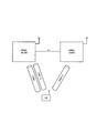
図1に示すように、本実施形態に係る移動通信システムは、無線基地局eNB#1と、無線基地局eNB#2とを具備している。 As shown in FIG. 1, the mobile communication system according to the present embodiment includes a radio base station eNB # 1 and a radio base station eNB # 2.
本実施形態に係る移動通信システムでは、無線基地局eNB#1は、マスター無線基地局(或いは、マクロセルを管理するマクロ無線基地局)M-eNBであり、無線基地局eNB#2は、スレーブ無線基地局(或いは、スモールセルを管理するスモール無線基地局)S-eNBであるものとする。 In the mobile communication system according to the present embodiment, the radio base station eNB # 1 is a master radio base station (or a macro radio base station that manages a macro cell) M-eNB, and the radio base station eNB # 2 is a slave radio. It is assumed that it is a base station (or a small radio base station that manages a small cell) S-eNB.
また、本実施形態に係る移動通信システムでは、移動局UEが、無線基地局eNB#1配下のセル及び無線基地局eNB#2配下のセルを用いた「Inter-eNB CA」を行うことができるように構成されている。 Moreover, in the mobile communication system according to the present embodiment, the mobile station UE can perform “Inter-eNB CA” using a cell under the radio base station eNB # 1 and a cell under the radio base station eNB # 2. It is configured as follows.
かかる「Inter-eNB CA」を行うために、無線基地局eNB#1及び移動局UEは、RRC(Radio Resource Contriol)レイヤ機能を具備しており、無線基地局eNB#2は、RRCレイヤ機能を具備していなくてもよい。 In order to perform such “Inter-eNB CA”, the radio base station eNB # 1 and the mobile station UE have an RRC (Radio Resource Control) layer function, and the radio base station eNB # 2 has an RRC layer function. It may not be provided.
かかる場合、無線基地局eNB#1のRRCレイヤ機能が、移動局UE宛ての全てのRRCメッセージを生成し、移動局UEに送信するように構成されている。 In such a case, the RRC layer function of the radio base station eNB # 1 is configured to generate all the RRC messages addressed to the mobile station UE and transmit them to the mobile station UE.
或いは、かかる「Inter-eNB CA」を行うために、無線基地局eNB#1、無線基地局eNB#2及び移動局UEの全てが、RRC(Radio Resource Contriol)レイヤ機能を具備していてもよい。 Alternatively, in order to perform such “Inter-eNB CA”, all of the radio base station eNB # 1, the radio base station eNB # 2, and the mobile station UE may have an RRC (Radio Resource Control) layer function. .
かかる場合、無線基地局eNB#1のRRCレイヤ機能及び無線基地局eNB#2のRRCレイヤ機能の各々が、移動局UE宛てのRRCメッセージを生成し、移動局UEに送信するように構成されている。 In such a case, each of the RRC layer function of the radio base station eNB # 1 and the RRC layer function of the radio base station eNB # 2 is configured to generate an RRC message addressed to the mobile station UE and transmit it to the mobile station UE. Yes.
なお、無線基地局eNB#1のRRCレイヤ機能によって生成されるRRCメッセージ及び無線基地局eNB#2のRRCレイヤ機能によって生成されるRRCメッセージは、LTE方式の規定によって決められるものとする。 Note that the RRC message generated by the RRC layer function of the radio base station eNB # 1 and the RRC message generated by the RRC layer function of the radio base station eNB # 2 are determined according to the LTE scheme.
図1に示すように、かかる「Inter-eNB CA」が行われている場合、SRB0、SRB1及びSRB2が、移動局UEと無線基地局eNB#1との間で確立されるように構成されている。 As shown in FIG. 1, when such “Inter-eNB CA” is performed, SRB0, SRB1, and SRB2 are configured to be established between the mobile station UE and the radio base station eNB # 1. Yes.
ここで、SRB0は、RRCコネクションの確立及び再確立や、RRCコネクション要求信号の拒絶といったRRCコネクションの確立のための基本的なシグナリングのみ送信するように構成されているため、移動局UEと無線基地局eNB#1との間にのみ確立され、移動局UEと無線基地局eNB#2との間では確立されないように構成されている。 Here, the SRB0 is configured to transmit only basic signaling for establishing the RRC connection such as establishment and re-establishment of the RRC connection and rejection of the RRC connection request signal. It is configured to be established only between the station eNB # 1 and not established between the mobile station UE and the radio base station eNB # 2.
また、SRB1は、SRB2の確立前に、NAS(Non Access Stratum)メッセージと共に、RRCメッセージを送信するためのベアラである。
The
さらに、SRB2は、NASメッセージと共に、「logged measurement information」を含むRRCメッセージを送信するためのベアラであり、SRB1よりも低い優先権を有しており、「security action」の後に、E-UTRANによって設定される。 Further, SRB2 is a bearer for transmitting an RRC message including “logged measurement information” along with the NAS message, and has a lower priority than SRB1, and after “security action”, the E-UTRAN Is set.
SRB1及びSRB2を介して送信すべきRRCメッセージは、無線基地局eNB#1によって送信されてもよいし、無線基地局eNB#2によって送信されてもよい。 The RRC message to be transmitted via the SRB1 and the SRB2 may be transmitted by the radio base station eNB # 1, or may be transmitted by the radio base station eNB # 2.
したがって、かかる「Inter-eNB CA」が行われている場合、移動局UEと無線基地局eNB#1との間で確立されているSRB1及びSRB2と同じ設定内容のSRB1及びSRB2が、移動局UEと無線基地局eNB#2との間で確立されるように構成されている。 Therefore, when such “Inter-eNB CA” is performed, SRB1 and SRB2 having the same setting contents as SRB1 and SRB2 established between the mobile station UE and the radio base station eNB # 1 are transferred to the mobile station UE. And the radio base station eNB # 2.
ここで、無線基地局eNB#2が追加される場合、かかる無線基地局はeNB#2は、移動局UEに対して、既存の「SRB-ToAddMod」を送信することによって、移動局UEと無線基地局eNB#1との間で確立されているSRB1及びSRB2と同じ設定内容となるように、移動局UEと無線基地局eNB#2との間でSRB1及びSRB2を確立するように構成されている。 Here, when the radio base station eNB # 2 is added, the radio base station transmits the existing “SRB-ToAddMod” to the mobile station UE, so that the eNB # 2 It is configured to establish SRB1 and SRB2 between the mobile station UE and the radio base station eNB # 2 so as to have the same setting contents as SRB1 and SRB2 established with the base station eNB # 1 Yes.
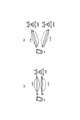
以下、図2及び図3を参照して、本実施形態に係る移動通信システムの動作について説明する。 Hereinafter, the operation of the mobile communication system according to the present embodiment will be described with reference to FIG. 2 and FIG.
図2に示すように、移動局UEと無線基地局eNB#1との間でSRB0/SRB1/SRB2が設定されている状態で、無線基地局eNB#2を追加すること(移動局UEが、無線基地局eNB#1配下のセル及び無線基地局eNB#2配下のセルを用いた「Inter-eNB CA」を行うこと)が決定されると、ステップS1001において、無線基地局eNB#2は、移動局UEに対して、図3に示す「SRB-ToAddMod」を送信する。 As shown in FIG. 2, in a state where SRB0 / SRB1 / SRB2 is set between the mobile station UE and the radio base station eNB # 1, the radio base station eNB # 2 is added (the mobile station UE When “Inter-eNB CA” using a cell under radio base station eNB # 1 and a cell under radio base station eNB # 2 is determined), in step S1001, the radio base station eNB # 2 “SRB-ToAddMod” shown in FIG. 3 is transmitted to the mobile station UE.
かかる「SRB-To-AddMod」は、移動局UEと無線基地局eNB#1との間で確立されているSRB1及びSRBと同じ設定内容のSRB1及びSRB2を、移動局UEと無線基地局eNB#2との間で確立するように指示するものである。 The “SRB-To-AddMod” is obtained by replacing the SRB1 and SRB2 having the same setting contents as the SRB1 and SRB established between the mobile station UE and the radio base station eNB # 1, with the mobile station UE and the radio base station eNB #. 2 is instructed to be established between the two.
具体的には、無線基地局eNB#2は、図3に示すように、「SRB-To-AddMod」内の情報要素「srb-Idenity」によってSRBの識別情報を設定し、「SRB-ToAddMod」内の情報要素「rlc-Config」によって、RLCレイヤにおける設定を行い、「SRB-ToAddMod」内の情報要素「logicalChannelConfig」によって、論理チャネルに係る設定を行うように構成されている。 Specifically, as illustrated in FIG. 3, the radio base station eNB # 2 sets the identification information of the SRB by the information element “srb-Identity” in the “SRB-To-AddMod”, and sets “SRB-ToAddMod”. The information element “rlc-Config” in FIG. 6 is used for setting in the RLC layer, and the information element “logicalChannelConfig” in “SRB-ToAddMod” is used for setting related to the logical channel.
ステップS1002において、移動局UEと無線基地局eNB#2との間でSRB1及びSRB2が確立されると、無線基地局eNB#2は、SRB1及びSRB2を介して送信すべきRRCメッセージについて、確立されたSRB1及びSRB2を介して移動局UEに対して送信する。 When SRB1 and SRB2 are established between the mobile station UE and the radio base station eNB # 2 in step S1002, the radio base station eNB # 2 is established for the RRC message to be transmitted via the SRB1 and SRB2. It transmits with respect to the mobile station UE via SRB1 and SRB2.
なお、SRB0を介して送信すべきRRCメッセージについては、移動局UEと無線基地局eNB#1との間で確立されているSRB0を介して、無線基地局eNB#1から移動局UEに対して送信される。 In addition, about the RRC message which should be transmitted via SRB0, radio | wireless base station eNB # 1 is transmitted with respect to the mobile station UE via SRB0 established between the mobile station UE and radio base station eNB # 1. Sent.
本実施形態に係る移動通信システムによれば、上述の「Inter-eNB CA」が行われている場合に、移動局UEと無線基地局eNB#2との間で確立されているSRB1及びSRB2は、移動局UEと無線基地局eNB#1との間で確立されているSRB1及びSRB2と同一の設定内容を有しているため、移動局UEは、既存のLTE方式と同様に、1本のSRB1及び1本のSRB2が確立されているように見え、RRCメッセージを、どの無線基地局eNBとの間で確立しているSRB1及びSRB2を介して受信するべきか判断する必要がなくなるという効果を奏する。 According to the mobile communication system according to the present embodiment, when the above-described “Inter-eNB CA” is performed, SRB1 and SRB2 established between the mobile station UE and the radio base station eNB # 2 are Since the mobile station UE has the same setting content as the SRB1 and SRB2 established between the mobile station UE and the radio base station eNB # 1, the mobile station UE has one single line as in the existing LTE scheme. The effect is that SRB1 and one SRB2 appear to be established, and it is not necessary to determine via which SRB1 and SRB2 the RRC message should be received with which radio base station eNB. Play.
(本発明の第2の実施形態に係る移動通信システム)
以下、図4及び図5を参照して、本発明の第2の実施形態に係る移動通信システムについて、上述の第2の実施形態に係る移動通信システムとの相違点に着目して説明する。
(Mobile communication system according to the second embodiment of the present invention)
Hereinafter, the mobile communication system according to the second embodiment of the present invention will be described with reference to FIG. 4 and FIG. 5 while focusing on the differences from the mobile communication system according to the second embodiment described above.
図4に示すように、上述の「Inter-eNB CA」が行われている場合、SRB0、SRB1及びSRB2が、移動局UEと無線基地局eNB#1との間で確立されるように構成されている。
As shown in FIG. 4, when the above-mentioned “Inter-eNB CA” is performed, SRB0, SRB1, and SRB2 are configured to be established between the mobile station UE and the radio base
一方、上述の「Inter-eNB CA」が行われている場合、SRB1及びSRB2が、移動局UEと無線基地局eNB#2との間で確立されるように構成されている。
On the other hand, when the above-mentioned “Inter-eNB CA” is performed, the SRB1 and the SRB2 are configured to be established between the mobile station UE and the radio base
かかる場合、無線基地局eNB#2は、移動局UEと無線基地局eNB#1との間で確立されているSRB1及びSRB2の設定情報を用いて、移動局UEに対して、かかるSRB1及びSRB2上で送信されるべき信号を送信するように構成されている。
In such a case, the radio base
ここで、無線基地局eNB#2は、無線基地局eNB#2との間のX2インターフェイスを介して、かかるSRB1及びSRB2の設定情報を取得するように構成されている。
Here, the radio base
以下、図5を参照して、本実施形態に係る移動通信システムの動作について説明する。 Hereinafter, the operation of the mobile communication system according to the present embodiment will be described with reference to FIG.
図5に示すように、移動局UEと無線基地局eNB#1との間でSRB0/SRB1/SRB2が設定されている状態で、無線基地局eNB#1は、ステップS2001において、無線基地局eNB#2を追加すること(移動局UEが、無線基地局eNB#1配下のセル及び無線基地局eNB#2配下のセルを用いた「Inter-eNB CA」を行うこと)を決定すると、ステップS2002において、無線基地局eNB#2に対して、移動局UEと無線基地局eNB#1との間で確立されているSRB1及びSRB2の設定情報を送信する。
As shown in FIG. 5, in a state where SRB0 / SRB1 / SRB2 is set between the mobile station UE and the radio base
無線基地局eNB#2は、ステップS2002において、かかる設定情報を受信した後、ステップS2003において、かかる設定を確認して旨を、無線基地局eNB#1に対して通知する。
After receiving the setting information in step S2002, the radio base
その後、無線基地局eNB#1は、ステップS2004において、「RRCConnectionReconfiguration」を移動局UEに対して送信し、無線基地局eNB#2の追加を指示する。
Thereafter, in step S2004, the radio base
移動局UEは、ステップS2005において、「RRCConnectionReconfigurationComplete」を無線基地局eNB#1に対して送信すると共に、ステップS2006において、無線基地局eNB#1との間で確立されているSRB1及びSRB2の設定情報を用いて、無線基地局eNB#2経由でSRB1及びSRB2上でデータを送るための設定を適用する。
In step S2005, the mobile station UE transmits “RRCConnectionReconfigurationComplete” to the radio base
なお、SRB0を介して送信すべきRRCメッセージについては、移動局UEと無線基地局eNB#1との間で確立されているSRB0を介して、無線基地局eNB#1から移動局UEに対して送信される。
In addition, about the RRC message which should be transmitted via SRB0, radio | wireless base
本実施形態に係る移動通信システムによれば、上述の「Inter-eNB CA」が行われている場合には、移動局UEと無線基地局eNB#2との間でSRB1及びSRB2を確立しなくても、無線基地局eNB#2は、移動局UEと無線基地局eNB#1との間で確立されているSRB1及びSRB2の設定情報を用いて、SRB1及びSRB2を介して送信すべきRRCメッセージを送信するように構成されているため、移動局UEは、既存のLTE方式と同様に、1本のSRB1及び1本のSRB2が確立されているように見え、RRCメッセージを、どの無線基地局eNBとの間で確立しているSRB1及びSRB2を介して受信するべきか判断する必要がなくなるという効果を奏する。
According to the mobile communication system according to the present embodiment, when the above-mentioned “Inter-eNB CA” is performed, SRB1 and SRB2 are not established between the mobile station UE and the radio base
以上に述べた本実施形態の特徴は、以下のように表現されていてもよい。 The characteristics of the present embodiment described above may be expressed as follows.
本実施形態の第1の特徴は、移動局UEが、無線基地局MeNB(マスター無線基地局)配下のセル及び無線基地局SeNB(スレーブ無線基地局)配下のセルを用いた「Inter-eNB CA(キャリアアグリゲーション)」を行うことができるように構成されている移動通信システムであって、かかる「Inter-eNB CA」が行われている場合、SRB0、SRB1及びSRB2は、移動局UEと無線基地局MeNBとの間で確立されるように構成されており、無線基地局SeNBが追加される場合、かかる無線基地局SeNBは、移動局UEに対して、「SRB-ToAddMod(SRBを追加又は変更するための信号)」を送信することによって、移動局UEと無線基地局MeNBとの間で確立されているSRB1及びSRB2と同じ設定内容となるように、移動局UEと無線基地局SeNBとの間でSRB1及びSRB2を確立するように構成されていることを要旨する。 The first feature of the present embodiment is that the mobile station UE uses a cell under the control of the radio base station MeNB (master radio base station) and a cell under the control of the radio base station SeNB (slave radio base station). (Carrier Aggregation) ”is a mobile communication system configured to perform“ Inter-eNB CA ”, and when the“ Inter-eNB CA ”is performed, the SRB0, SRB1, and SRB2 When the radio base station SeNB is added and the radio base station SeNB is added to the station MeNB, the radio base station SeNB adds “SRB-ToAddMod (SRB addition or change) to the mobile station UE. SRB1 and SR established between the mobile station UE and the radio base station MeNB by transmitting The gist is that SRB1 and SRB2 are established between the mobile station UE and the radio base station SeNB so as to have the same setting content as B2.
本実施形態の第2の特徴は、移動局UEが、無線基地局MeNB配下のセル及び無線基地局SeNB配下のセルを用いた「Inter-eNB CA」を行うことができるように構成されている移動通信システムであって、かかる「Inter-eNB CA」が行われている場合、SRB0、SRB1及びSRB2は、移動局UEと無線基地局MeNBとの間で確立されるように構成されており、無線基地局MeNBは、無線基地局SeNBに対して、上述のSRB1及びSRB2の設定情報を通知すると共に、移動局UEに対して、無線基地局SeNBを追加するように指示するように構成されており、移動局UEは、かかる指示に応じて、無線基地局MeNBとの間で確立されているSRB1及びSRB2の設定情報を用いて、無線基地局SeNB経由でSRB1及びSRB2上でRRCメッセージ(信号)を送るための設定を適用するように構成されていることを要旨とする。 The second feature of the present embodiment is configured such that the mobile station UE can perform “Inter-eNB CA” using a cell under the radio base station MeNB and a cell under the radio base station SeNB. In the mobile communication system, when such “Inter-eNB CA” is performed, the SRB0, SRB1, and SRB2 are configured to be established between the mobile station UE and the radio base station MeNB, The radio base station MeNB is configured to notify the radio base station SeNB of the setting information of the above-described SRB1 and SRB2, and to instruct the mobile station UE to add the radio base station SeNB. In response to the instruction, the mobile station UE uses the setting information of the SRB1 and SRB2 established with the radio base station MeNB, It is summarized as that is configured to apply the settings to send an RRC message (signal) on SRB1 and SRB2 via eNB.
なお、上述の無線基地局MeNB/SeNBや移動局UEの動作は、ハードウェアによって実施されてもよいし、プロセッサによって実行されるソフトウェアモジュールによって実施されてもよいし、両者の組み合わせによって実施されてもよい。 The operations of the radio base station MeNB / SeNB and the mobile station UE described above may be implemented by hardware, may be implemented by a software module executed by a processor, or may be implemented by a combination of both. Also good.
ソフトウェアモジュールは、RAM(Random Access Memory)や、フラッシュメモリや、ROM(Read Only Memory)や、EPROM(Erasable Programmable ROM)や、EEPROM(Electronically Erasable and Programmable ROM)や、レジスタや、ハードディスクや、リムーバブルディスクや、CD-ROMといった任意形式の記憶媒体内に設けられていてもよい。 The software module includes a RAM (Random Access Memory), a flash memory, a ROM (Read Only Memory), an EPROM (Erasable Programmable ROM), an EEPROM (Electronically Erasable and Programmable ROM, a hard disk, a registerable ROM, a hard disk). Alternatively, it may be provided in a storage medium of an arbitrary format such as a CD-ROM.
かかる記憶媒体は、プロセッサが当該記憶媒体に情報を読み書きできるように、当該プロセッサに接続されている。また、かかる記憶媒体は、プロセッサに集積されていてもよい。また、かかる記憶媒体及びプロセッサは、ASIC内に設けられていてもよい。かかるASICは、無線基地局MeNB/SeNBや移動局UE内に設けられていてもよい。また、かかる記憶媒体及びプロセッサは、ディスクリートコンポーネントとして無線基地局MeNB/SeNBや移動局UE内に設けられていてもよい。 Such a storage medium is connected to the processor so that the processor can read and write information from and to the storage medium. Further, such a storage medium may be integrated in the processor. Such a storage medium and processor may be provided in the ASIC. Such an ASIC may be provided in the radio base station MeNB / SeNB or the mobile station UE. Further, the storage medium and the processor may be provided in the radio base station MeNB / SeNB or the mobile station UE as a discrete component.
以上、上述の実施形態を用いて本発明について詳細に説明したが、当業者にとっては、本発明が本明細書中に説明した実施形態に限定されるものではないということは明らかである。本発明は、特許請求の範囲の記載により定まる本発明の趣旨及び範囲を逸脱することなく修正及び変更態様として実施することができる。従って、本明細書の記載は、例示説明を目的とするものであり、本発明に対して何ら制限的な意味を有するものではない。 Although the present invention has been described in detail using the above-described embodiments, it is obvious to those skilled in the art that the present invention is not limited to the embodiments described in this specification. The present invention can be implemented as modified and changed modes without departing from the spirit and scope of the present invention defined by the description of the scope of claims. Therefore, the description of the present specification is for illustrative purposes and does not have any limiting meaning to the present invention.
UE…移動局
eNB#1(MeNB)/eNB#2(SeNB)…無線基地局
UE ... mobile station eNB # 1 (MeNB) / eNB # 2 (SeNB) ... radio base station
Claims (2)
前記キャリアアグリゲーションが行われている場合、SRB0、SRB1及びSRB2は、前記移動局と前記マスター無線基地局との間で確立されるように構成されており、
前記スレーブ無線基地局が追加される場合、該スレーブ無線基地局は、前記移動局に対して、SRBを追加又は変更するための信号を送信することによって、該移動局と前記マスター無線基地局との間で確立されている前記SRB1及び前記SRB2と同じ設定内容となるように、該移動局と前記スレーブ無線基地局との間でSRB1及びSRB2を確立するように構成されていることを特徴とする移動通信システム。 A mobile communication system configured to be able to perform carrier aggregation using a cell under the control of a master radio base station and a cell under the control of a slave radio base station,
When the carrier aggregation is performed, SRB0, SRB1 and SRB2 are configured to be established between the mobile station and the master radio base station,
When the slave radio base station is added, the slave radio base station transmits a signal for adding or changing an SRB to the mobile station, so that the mobile station and the master radio base station The SRB1 and the SRB2 are configured to be established between the mobile station and the slave radio base station so as to have the same setting contents as the SRB1 and the SRB2 established between the mobile station and the slave radio base station. Mobile communication system.
前記キャリアアグリゲーションが行われている場合、SRB0、SRB1及びSRB2は、前記移動局と前記マスター無線基地局との間で確立されるように構成されており、
前記マスター無線基地局は、前記スレーブ無線基地局に対して、前記SRB1及び前記SRB2の設定情報を通知すると共に、前記移動局に対して、該スレーブ無線基地局を追加するように指示するように構成されており、
前記移動局は、前記指示に応じて、前記マスター無線基地局との間で確立されている前記SRB1及び前記SRB2の設定情報を用いて、前記スレーブ無線基地局経由で該SRB1及び該SRB2上で信号を送るための設定を適用するように構成されていることを特徴とする移動通信システム。 A mobile communication system configured to be able to perform carrier aggregation using a cell under the control of a master radio base station and a cell under the control of a slave radio base station,
When the carrier aggregation is performed, SRB0, SRB1 and SRB2 are configured to be established between the mobile station and the master radio base station,
The master radio base station notifies the slave radio base station of the setting information of the SRB1 and the SRB2, and instructs the mobile station to add the slave radio base station. Configured,
In response to the instruction, the mobile station uses the setting information of the SRB1 and the SRB2 established with the master radio base station on the SRB1 and the SRB2 via the slave radio base station. A mobile communication system configured to apply a setting for sending a signal.
Priority Applications (4)
| Application Number | Priority Date | Filing Date | Title |
|---|---|---|---|
| JP2013200657A JP6231341B2 (en) | 2013-09-26 | 2013-09-26 | Mobile communication system |
| PCT/JP2014/075468 WO2015046352A1 (en) | 2013-09-26 | 2014-09-25 | Mobile communication system |
| CN201480052922.5A CN105580472A (en) | 2013-09-26 | 2014-09-25 | Mobile communication system |
| US15/024,794 US20160249389A1 (en) | 2013-09-26 | 2014-09-25 | Mobile communication system |
Applications Claiming Priority (1)
| Application Number | Priority Date | Filing Date | Title |
|---|---|---|---|
| JP2013200657A JP6231341B2 (en) | 2013-09-26 | 2013-09-26 | Mobile communication system |
Related Child Applications (1)
| Application Number | Title | Priority Date | Filing Date |
|---|---|---|---|
| JP2017202469A Division JP2018029381A (en) | 2017-10-19 | 2017-10-19 | Mobile communication system |
Publications (2)
| Publication Number | Publication Date |
|---|---|
| JP2015070341A JP2015070341A (en) | 2015-04-13 |
| JP6231341B2 true JP6231341B2 (en) | 2017-11-15 |
Family
ID=52743483
Family Applications (1)
| Application Number | Title | Priority Date | Filing Date |
|---|---|---|---|
| JP2013200657A Expired - Fee Related JP6231341B2 (en) | 2013-09-26 | 2013-09-26 | Mobile communication system |
Country Status (4)
| Country | Link |
|---|---|
| US (1) | US20160249389A1 (en) |
| JP (1) | JP6231341B2 (en) |
| CN (1) | CN105580472A (en) |
| WO (1) | WO2015046352A1 (en) |
Cited By (1)
| Publication number | Priority date | Publication date | Assignee | Title |
|---|---|---|---|---|
| JP2018029381A (en) * | 2017-10-19 | 2018-02-22 | 株式会社Nttドコモ | Mobile communication system |
Families Citing this family (4)
| Publication number | Priority date | Publication date | Assignee | Title |
|---|---|---|---|---|
| CN113163512B (en) * | 2013-11-15 | 2023-10-24 | 荣耀终端有限公司 | Method for establishing radio bearer and base station |
| CN106559916A (en) * | 2015-09-29 | 2017-04-05 | 电信科学技术研究院 | A kind of method and its device, base station and terminal for setting up auxiliary signaling link |
| WO2017195854A1 (en) * | 2016-05-12 | 2017-11-16 | 株式会社Nttドコモ | Wireless communication system and user device |
| CN108633018B (en) | 2017-03-23 | 2024-02-02 | 华为技术有限公司 | Configuration method, device and system |
Family Cites Families (8)
| Publication number | Priority date | Publication date | Assignee | Title |
|---|---|---|---|---|
| CA2775371C (en) * | 2009-09-25 | 2018-03-13 | Research In Motion Limited | System and method for multi-carrier network operation |
| US20110205976A1 (en) * | 2010-02-19 | 2011-08-25 | Nokia Siemens Networks Oy | UE Specific Signaling Carrier Indicator For Carrier Aggregation |
| CN102448058B (en) * | 2011-01-10 | 2014-04-30 | 华为技术有限公司 | Method and device for protecting data on Un interface |
| EP2966800A1 (en) * | 2011-04-29 | 2016-01-13 | Interdigital Patent Holdings, Inc. | Carrier aggregation with subframe restrictions |
| WO2013112021A1 (en) * | 2012-01-27 | 2013-08-01 | 삼성전자 주식회사 | Method and apparatus for transmitting and receiving data by using plurality of carriers in mobile communication systems |
| KR102040883B1 (en) * | 2012-08-23 | 2019-11-05 | 인터디지탈 패튼 홀딩스, 인크 | Operating with multiple schedulers in a wireless system |
| JP6149928B2 (en) * | 2013-05-10 | 2017-06-21 | 富士通株式会社 | Wireless communication method, wireless communication system, and wireless station |
| KR102235177B1 (en) * | 2013-07-26 | 2021-04-02 | 엘지전자 주식회사 | Method for calculating an amount of data available for transmission and a device therefor |
-
2013
- 2013-09-26 JP JP2013200657A patent/JP6231341B2/en not_active Expired - Fee Related
-
2014
- 2014-09-25 CN CN201480052922.5A patent/CN105580472A/en active Pending
- 2014-09-25 US US15/024,794 patent/US20160249389A1/en not_active Abandoned
- 2014-09-25 WO PCT/JP2014/075468 patent/WO2015046352A1/en active Application Filing
Cited By (1)
| Publication number | Priority date | Publication date | Assignee | Title |
|---|---|---|---|---|
| JP2018029381A (en) * | 2017-10-19 | 2018-02-22 | 株式会社Nttドコモ | Mobile communication system |
Also Published As
| Publication number | Publication date |
|---|---|
| CN105580472A (en) | 2016-05-11 |
| US20160249389A1 (en) | 2016-08-25 |
| JP2015070341A (en) | 2015-04-13 |
| WO2015046352A1 (en) | 2015-04-02 |
Similar Documents
| Publication | Publication Date | Title |
|---|---|---|
| US9338711B2 (en) | Method of handling handover for network of wireless communication system and communication device thereof | |
| CN105917727B (en) | User equipment, evolved node B and method thereof | |
| CN105917716B (en) | User equipment, evolved node B and method thereof | |
| JP5438046B2 (en) | Mobile communication method and radio base station | |
| KR102127195B1 (en) | Wireless communication system, wireless stations, wireless terminal, communication control method, and computer-readable medium | |
| US9014145B2 (en) | Radio base station and mobile station | |
| US20150282239A1 (en) | Method and apparatus for managing dual connection establishment | |
| JP6231341B2 (en) | Mobile communication system | |
| JP5871750B2 (en) | Mobile communication system, radio base station and mobile station | |
| WO2015155599A2 (en) | Method of refreshing a key in a user plane architecture 1a based dual connectivity situation | |
| JP6180102B2 (en) | Mobile communication method, radio base station, and mobile station | |
| WO2021161621A1 (en) | Ran node, radio terminal, and method for same | |
| US9668174B2 (en) | Mobile communication method | |
| CA2886799C (en) | Radio base station and mobile station | |
| JP2018029381A (en) | Mobile communication system | |
| JP5696186B2 (en) | Mobile station and radio base station | |
| JP6023530B2 (en) | Mobile communication method | |
| WO2015022986A1 (en) | Mobile communication method and mobile communication system | |
| EP3016462A1 (en) | Mobile communication system and mobile communication method | |
| JP6055255B2 (en) | Mobile communication method | |
| JP2015185938A (en) | Base station device, architecture information acquisition method, and computer program | |
| JP2014068119A (en) | Mobile communication method and radio base station |
Legal Events
| Date | Code | Title | Description |
|---|---|---|---|
| A621 | Written request for application examination |
Free format text: JAPANESE INTERMEDIATE CODE: A621 Effective date: 20160912 |
|
| TRDD | Decision of grant or rejection written | ||
| A01 | Written decision to grant a patent or to grant a registration (utility model) |
Free format text: JAPANESE INTERMEDIATE CODE: A01 Effective date: 20170919 |
|
| A61 | First payment of annual fees (during grant procedure) |
Free format text: JAPANESE INTERMEDIATE CODE: A61 Effective date: 20171019 |
|
| R150 | Certificate of patent or registration of utility model |
Ref document number: 6231341 Country of ref document: JP Free format text: JAPANESE INTERMEDIATE CODE: R150 |
|
| LAPS | Cancellation because of no payment of annual fees |