JP6230435B2 - Data processing apparatus, control method thereof, and program - Google Patents

Data processing apparatus, control method thereof, and program Download PDF

Info

Publication number
JP6230435B2
JP6230435B2 JP2014018672A JP2014018672A JP6230435B2 JP 6230435 B2 JP6230435 B2 JP 6230435B2 JP 2014018672 A JP2014018672 A JP 2014018672A JP 2014018672 A JP2014018672 A JP 2014018672A JP 6230435 B2 JP6230435 B2 JP 6230435B2
Authority
JP
Japan
Prior art keywords
data
communication
unit
processing apparatus
data processing
Prior art date
Legal status (The legal status is an assumption and is not a legal conclusion. Google has not performed a legal analysis and makes no representation as to the accuracy of the status listed.)
Active
Application number
JP2014018672A
Other languages
Japanese (ja)
Other versions
JP2015146521A (en
Inventor
四宮 岳史
岳史 四宮
Current Assignee (The listed assignees may be inaccurate. Google has not performed a legal analysis and makes no representation or warranty as to the accuracy of the list.)
Canon Inc
Original Assignee
Canon Inc
Priority date (The priority date is an assumption and is not a legal conclusion. Google has not performed a legal analysis and makes no representation as to the accuracy of the date listed.)
Filing date
Publication date
Application filed by Canon Inc filed Critical Canon Inc
Priority to JP2014018672A priority Critical patent/JP6230435B2/en
Priority to US14/610,986 priority patent/US10216477B2/en
Publication of JP2015146521A publication Critical patent/JP2015146521A/en
Application granted granted Critical
Publication of JP6230435B2 publication Critical patent/JP6230435B2/en
Active legal-status Critical Current
Anticipated expiration legal-status Critical

Links

Images

Classifications

    • GPHYSICS
    • G06COMPUTING; CALCULATING OR COUNTING
    • G06FELECTRIC DIGITAL DATA PROCESSING
    • G06F7/00Methods or arrangements for processing data by operating upon the order or content of the data handled
    • G06F7/22Arrangements for sorting or merging computer data on continuous record carriers, e.g. tape, drum, disc
    • G06F7/24Sorting, i.e. extracting data from one or more carriers, rearranging the data in numerical or other ordered sequence, and rerecording the sorted data on the original carrier or on a different carrier or set of carriers sorting methods in general
    • HELECTRICITY
    • H04ELECTRIC COMMUNICATION TECHNIQUE
    • H04NPICTORIAL COMMUNICATION, e.g. TELEVISION
    • H04N1/00Scanning, transmission or reproduction of documents or the like, e.g. facsimile transmission; Details thereof
    • H04N1/00127Connection or combination of a still picture apparatus with another apparatus, e.g. for storage, processing or transmission of still picture signals or of information associated with a still picture
    • H04N1/00281Connection or combination of a still picture apparatus with another apparatus, e.g. for storage, processing or transmission of still picture signals or of information associated with a still picture with a telecommunication apparatus, e.g. a switched network of teleprinters for the distribution of text-based information, a selective call terminal
    • H04N1/00307Connection or combination of a still picture apparatus with another apparatus, e.g. for storage, processing or transmission of still picture signals or of information associated with a still picture with a telecommunication apparatus, e.g. a switched network of teleprinters for the distribution of text-based information, a selective call terminal with a mobile telephone apparatus
    • GPHYSICS
    • G06COMPUTING; CALCULATING OR COUNTING
    • G06FELECTRIC DIGITAL DATA PROCESSING
    • G06F16/00Information retrieval; Database structures therefor; File system structures therefor
    • G06F16/20Information retrieval; Database structures therefor; File system structures therefor of structured data, e.g. relational data
    • GPHYSICS
    • G03PHOTOGRAPHY; CINEMATOGRAPHY; ANALOGOUS TECHNIQUES USING WAVES OTHER THAN OPTICAL WAVES; ELECTROGRAPHY; HOLOGRAPHY
    • G03BAPPARATUS OR ARRANGEMENTS FOR TAKING PHOTOGRAPHS OR FOR PROJECTING OR VIEWING THEM; APPARATUS OR ARRANGEMENTS EMPLOYING ANALOGOUS TECHNIQUES USING WAVES OTHER THAN OPTICAL WAVES; ACCESSORIES THEREFOR
    • G03B2206/00Systems for exchange of information between different pieces of apparatus, e.g. for exchanging trimming information, for photo finishing
    • HELECTRICITY
    • H04ELECTRIC COMMUNICATION TECHNIQUE
    • H04NPICTORIAL COMMUNICATION, e.g. TELEVISION
    • H04N2201/00Indexing scheme relating to scanning, transmission or reproduction of documents or the like, and to details thereof
    • H04N2201/0008Connection or combination of a still picture apparatus with another apparatus
    • H04N2201/0034Details of the connection, e.g. connector, interface
    • H04N2201/0048Type of connection
    • H04N2201/006Using near field communication, e.g. an inductive loop
    • HELECTRICITY
    • H04ELECTRIC COMMUNICATION TECHNIQUE
    • H04NPICTORIAL COMMUNICATION, e.g. TELEVISION
    • H04N2201/00Indexing scheme relating to scanning, transmission or reproduction of documents or the like, and to details thereof
    • H04N2201/0077Types of the still picture apparatus
    • H04N2201/0084Digital still camera
    • HELECTRICITY
    • H04ELECTRIC COMMUNICATION TECHNIQUE
    • H04NPICTORIAL COMMUNICATION, e.g. TELEVISION
    • H04N2201/00Indexing scheme relating to scanning, transmission or reproduction of documents or the like, and to details thereof
    • H04N2201/32Circuits or arrangements for control or supervision between transmitter and receiver or between image input and image output device, e.g. between a still-image camera and its memory or between a still-image camera and a printer device
    • H04N2201/3201Display, printing, storage or transmission of additional information, e.g. ID code, date and time or title
    • H04N2201/3212Display, printing, storage or transmission of additional information, e.g. ID code, date and time or title of data relating to a job, e.g. communication, capture or filing of an image
    • H04N2201/3214Display, printing, storage or transmission of additional information, e.g. ID code, date and time or title of data relating to a job, e.g. communication, capture or filing of an image of a date
    • HELECTRICITY
    • H04ELECTRIC COMMUNICATION TECHNIQUE
    • H04NPICTORIAL COMMUNICATION, e.g. TELEVISION
    • H04N2201/00Indexing scheme relating to scanning, transmission or reproduction of documents or the like, and to details thereof
    • H04N2201/32Circuits or arrangements for control or supervision between transmitter and receiver or between image input and image output device, e.g. between a still-image camera and its memory or between a still-image camera and a printer device
    • H04N2201/3201Display, printing, storage or transmission of additional information, e.g. ID code, date and time or title
    • H04N2201/3212Display, printing, storage or transmission of additional information, e.g. ID code, date and time or title of data relating to a job, e.g. communication, capture or filing of an image
    • H04N2201/3215Display, printing, storage or transmission of additional information, e.g. ID code, date and time or title of data relating to a job, e.g. communication, capture or filing of an image of a time or duration
    • HELECTRICITY
    • H04ELECTRIC COMMUNICATION TECHNIQUE
    • H04NPICTORIAL COMMUNICATION, e.g. TELEVISION
    • H04N2201/00Indexing scheme relating to scanning, transmission or reproduction of documents or the like, and to details thereof
    • H04N2201/32Circuits or arrangements for control or supervision between transmitter and receiver or between image input and image output device, e.g. between a still-image camera and its memory or between a still-image camera and a printer device
    • H04N2201/3201Display, printing, storage or transmission of additional information, e.g. ID code, date and time or title
    • H04N2201/3225Display, printing, storage or transmission of additional information, e.g. ID code, date and time or title of data relating to an image, a page or a document
    • H04N2201/3253Position information, e.g. geographical position at time of capture, GPS data
    • HELECTRICITY
    • H04ELECTRIC COMMUNICATION TECHNIQUE
    • H04NPICTORIAL COMMUNICATION, e.g. TELEVISION
    • H04N2201/00Indexing scheme relating to scanning, transmission or reproduction of documents or the like, and to details thereof
    • H04N2201/32Circuits or arrangements for control or supervision between transmitter and receiver or between image input and image output device, e.g. between a still-image camera and its memory or between a still-image camera and a printer device
    • H04N2201/3201Display, printing, storage or transmission of additional information, e.g. ID code, date and time or title
    • H04N2201/3278Transmission
    • HELECTRICITY
    • H04ELECTRIC COMMUNICATION TECHNIQUE
    • H04NPICTORIAL COMMUNICATION, e.g. TELEVISION
    • H04N23/00Cameras or camera modules comprising electronic image sensors; Control thereof
    • H04N23/60Control of cameras or camera modules
    • H04N23/63Control of cameras or camera modules by using electronic viewfinders
    • H04N23/631Graphical user interfaces [GUI] specially adapted for controlling image capture or setting capture parameters
    • HELECTRICITY
    • H04ELECTRIC COMMUNICATION TECHNIQUE
    • H04NPICTORIAL COMMUNICATION, e.g. TELEVISION
    • H04N23/00Cameras or camera modules comprising electronic image sensors; Control thereof
    • H04N23/60Control of cameras or camera modules
    • H04N23/66Remote control of cameras or camera parts, e.g. by remote control devices
    • H04N23/661Transmitting camera control signals through networks, e.g. control via the Internet
    • HELECTRICITY
    • H04ELECTRIC COMMUNICATION TECHNIQUE
    • H04WWIRELESS COMMUNICATION NETWORKS
    • H04W28/00Network traffic management; Network resource management
    • H04W28/16Central resource management; Negotiation of resources or communication parameters, e.g. negotiating bandwidth or QoS [Quality of Service]
    • H04W28/18Negotiating wireless communication parameters
    • HELECTRICITY
    • H04ELECTRIC COMMUNICATION TECHNIQUE
    • H04WWIRELESS COMMUNICATION NETWORKS
    • H04W4/00Services specially adapted for wireless communication networks; Facilities therefor
    • H04W4/80Services using short range communication, e.g. near-field communication [NFC], radio-frequency identification [RFID] or low energy communication

Description

本発明は、他の装置と通信を行うデータ処理装置、その制御方法及びプログラムに関する。   The present invention relates to a data processing apparatus that communicates with another apparatus, a control method thereof, and a program.

従来、デジタルカメラに無線通信機能が搭載されており、デジタルカメラと携帯電話等とが互いに通信して画像を交換する機能が知られている。例えば特許文献1には、デジタルカメラと携帯電話とが無線通信を介して接続し、ユーザによって選択された画像データを送受信するシステムが開示されている。   2. Description of the Related Art Conventionally, a digital camera is equipped with a wireless communication function, and a function is known in which a digital camera and a mobile phone or the like communicate with each other to exchange images. For example, Patent Document 1 discloses a system in which a digital camera and a mobile phone are connected via wireless communication and transmit / receive image data selected by a user.

特開2003−8816号公報Japanese Patent Laid-Open No. 2003-8816

近年では、デジタルカメラが扱うことのできる記憶媒体の容量の増加も著しい。そのため、記憶媒体に記録できるコンテンツの量は非常に多くなってきている。
上述の特許文献1では、記憶媒体の容量の増加について何ら考慮されていない。そのため、記憶媒体に記録されているコンテンツの量によっては、ユーザが送信したいコンテンツを見つけるのに手間がかかるおそれがあった。
In recent years, the capacity of storage media that can be handled by digital cameras has also increased significantly. For this reason, the amount of content that can be recorded on a storage medium has become very large.
In Patent Document 1 described above, no consideration is given to an increase in the capacity of the storage medium. For this reason, depending on the amount of content recorded in the storage medium, it may be time-consuming to find the content that the user wants to transmit.

本発明は、上記課題を解決するためになされたものであって、複数のデータを保持しているデータ処理装置において、例えば他の装置に送信するデータをユーザが選択する際の手間を軽減することを目的とする。   The present invention has been made in order to solve the above-described problem, and in a data processing apparatus that holds a plurality of data, for example, reduces the effort when a user selects data to be transmitted to another apparatus. For the purpose.

本発明のデータ処理装置は、他の機器と通信を行う第一の通信手段と、前記他の機器と前記第一の通信手段より長距離の無線通信を行う第二の通信手段と、複数のデータを保持するデータ保持手段と、前記第二の通信手段による通信が開始する前に、前記第一の通信手段で取得したソート情報に基づいて前記データ保持手段が保持するデータをソートするための条件を決定してソートするソート手段とを備えたことを特徴とする。   The data processing apparatus according to the present invention includes a first communication unit that communicates with another device, a second communication unit that performs long-distance wireless communication with the other device, and a plurality of communication units. A data holding unit for holding data and a method for sorting the data held by the data holding unit based on the sort information acquired by the first communication unit before communication by the second communication unit is started. Sorting means for determining and sorting conditions is provided.

本発明によれば、複数のデータを保持しているデータ処理装置において、例えば他の装置に送信するデータをユーザが選択する際の手間を軽減することができる。   ADVANTAGE OF THE INVENTION According to this invention, in the data processing apparatus holding several data, the effort at the time of a user selecting the data transmitted, for example to another apparatus can be reduced.

第1の実施形態に係る通信システムの構成を示すブロック図である。1 is a block diagram showing a configuration of a communication system according to a first embodiment. 第1の実施形態に係るデジタルカメラの外観図である。1 is an external view of a digital camera according to a first embodiment. 第1の実施形態に係る携帯電話の外観図である。1 is an external view of a mobile phone according to a first embodiment. デジタルカメラ、携帯電話、移動体通信網及びインターネットの接続関係(ネットワーク構成)を説明するための図である。It is a figure for demonstrating the connection relationship (network structure) of a digital camera, a mobile telephone, a mobile communication network, and the internet. 第1の実施形態に係るデジタルカメラの動作を示すフローチャートである。It is a flowchart which shows operation | movement of the digital camera which concerns on 1st Embodiment. 第1の実施形態に係る携帯電話の動作を示すフローチャートである。It is a flowchart which shows operation | movement of the mobile telephone which concerns on 1st Embodiment. 第1の実施形態においてデジタルカメラが送信するデータを模式的に表す図である。It is a figure which represents typically the data which a digital camera transmits in 1st Embodiment. 第1の実施形態において携帯電話に表示される画面を説明するための図である。It is a figure for demonstrating the screen displayed on a mobile telephone in 1st Embodiment. 第1の実施形態においてデジタルカメラが受信するデータを模式的に表す図である。It is a figure which represents typically the data which a digital camera receives in 1st Embodiment. 第1の実施形態において記憶媒体に格納されている映像データを示す図である。It is a figure which shows the video data stored in the storage medium in 1st Embodiment. 第1の実施形態において記憶媒体に格納されている映像データをソートした結果を示す図である。It is a figure which shows the result of having sorted the video data stored in the storage medium in 1st Embodiment. 第1の実施形態において携帯電話の表示部におけるサムネイルデータ表示の例を示す図である。It is a figure which shows the example of the thumbnail data display in the display part of a mobile telephone in 1st Embodiment. 第2の実施形態に係るデジタルカメラの動作を示すフローチャートである。It is a flowchart which shows operation | movement of the digital camera which concerns on 2nd Embodiment. 第2の実施形態に係る携帯電話の動作を示すフローチャートである。It is a flowchart which shows operation | movement of the mobile telephone which concerns on 2nd Embodiment. 第2の実施形態において携帯電話に表示される画面を説明するための図である。It is a figure for demonstrating the screen displayed on a mobile telephone in 2nd Embodiment. 第2の実施形態においてデータ処理装置が受信するデータを模式的に表す図である。It is a figure which represents typically the data which a data processor receives in 2nd Embodiment. 第2の実施形態において記憶媒体に格納されている映像データを示す図である。It is a figure which shows the video data stored in the storage medium in 2nd Embodiment. 第2の実施形態において記憶媒体に格納されている映像データをソートした結果を示す図である。It is a figure which shows the result of having sorted the video data stored in the storage medium in 2nd Embodiment. 第2の実施形態においてデータ処理装置が生成するHTMLデータの例を示す図である。It is a figure which shows the example of the HTML data which a data processor produces | generates in 2nd Embodiment. 第3の実施形態に係るデジタルカメラの動作を示すフローチャートである。It is a flowchart which shows operation | movement of the digital camera which concerns on 3rd Embodiment. 第3の実施形態に係る携帯電話の動作を示すフローチャートである。It is a flowchart which shows operation | movement of the mobile telephone which concerns on 3rd Embodiment. 第3の実施形態においてデータ処理装置が受信するデータを模式的に表す図である。It is a figure which represents typically the data which a data processor receives in 3rd Embodiment. 第3の実施形態においてデータ処理装置の不揮発性メモリに保持されているPOIデータベースを模式的に表す図である。It is a figure which represents typically the POI database currently hold | maintained at the non-volatile memory of the data processor in 3rd Embodiment.

以下、添付図面を参照して、本発明の好適な実施形態について説明する。
(第1の実施形態)
第1の実施形態では、本発明のデータ処理装置をNFC(Near Field Communication)と無線LAN機能を有するデジタルカメラとした例を説明する。本実施形態では、データ処理装置が扱うデータを映像データ(静止画又は動画)とし、データ処理装置と通信しうる装置を、NFCと無線LAN機能を有する携帯電話(スマートフォン)とする。
Preferred embodiments of the present invention will be described below with reference to the accompanying drawings.
(First embodiment)
In the first embodiment, an example will be described in which the data processing apparatus of the present invention is a digital camera having NFC (Near Field Communication) and a wireless LAN function. In this embodiment, data handled by the data processing device is video data (still image or moving image), and a device that can communicate with the data processing device is a mobile phone (smart phone) having NFC and a wireless LAN function.

<装置説明>
図1は、第1の実施形態に係る通信システムの構成を示すブロック図である。
100はデジタルカメラである。150はデジタルカメラ100と無線LAN機能を用いて通信しうる携帯電話である。170は移動体通信網であり、携帯電話事業者によるネットワーク通信網である。移動体通信網170は、多数の基地局・基地局間ネットワーク・インターネットとのゲートウェイ等から構成される。携帯電話150は、移動体通信網170を介して他の携帯電話やインターネット上の端末と通信を行うことができる。180はインターネットであり、移動体通信網170はインターネット180とも接続されている。
<Device description>
FIG. 1 is a block diagram illustrating a configuration of a communication system according to the first embodiment.
Reference numeral 100 denotes a digital camera. A mobile phone 150 can communicate with the digital camera 100 using a wireless LAN function. Reference numeral 170 denotes a mobile communication network, which is a network communication network by a mobile phone operator. The mobile communication network 170 includes a large number of base stations, a network between base stations, a gateway to the Internet, and the like. The mobile phone 150 can communicate with other mobile phones and terminals on the Internet via the mobile communication network 170. Reference numeral 180 denotes the Internet, and the mobile communication network 170 is also connected to the Internet 180.

デジタルカメラ100では、システムバス113に対して、CPU101、メモリ102、不揮発性メモリ103、操作部104、表示部105、記憶媒体I/F106、撮像部108、画像処理部109、バッテリ110、近接無線通信部111、無線LAN部112が接続されている。
101はCPUであり、デジタルカメラ100の制御を司る(ソート手段)。CPU101はデジタルカメラ100の各部を制御し、ユーザの設定と操作に応じて画像を記録する。
102は書き換え可能なメモリであり、デジタルカメラ100を制御するプログラムが作業領域として使用する。メモリ102は、例えばRAM(半導体素子を利用した揮発性のメモリ)等からなる。
103は不揮発性メモリであり、デジタルカメラ100を制御するプログラムと、画像データや音声データ、その他のデータ等、プログラムが使用するデータを格納する。デジタルカメラ100に電源が投入されると、CPU101は不揮発性メモリ103からプログラムを読み込み、デジタルカメラ100の制御を開始する。不揮発性メモリ103は、例えばROM(半導体素子を利用した不揮発性のメモリ)等からなる。
In the digital camera 100, the CPU 101, the memory 102, the nonvolatile memory 103, the operation unit 104, the display unit 105, the storage medium I / F 106, the imaging unit 108, the image processing unit 109, the battery 110, and the proximity wireless communication are connected to the system bus 113. A communication unit 111 and a wireless LAN unit 112 are connected.
A CPU 101 controls the digital camera 100 (sorting means). The CPU 101 controls each part of the digital camera 100 and records an image in accordance with user settings and operations.
A rewritable memory 102 is used as a work area by a program for controlling the digital camera 100. The memory 102 includes, for example, a RAM (volatile memory using a semiconductor element).
Reference numeral 103 denotes a non-volatile memory that stores a program for controlling the digital camera 100 and data used by the program, such as image data, audio data, and other data. When the digital camera 100 is powered on, the CPU 101 reads a program from the nonvolatile memory 103 and starts controlling the digital camera 100. The nonvolatile memory 103 is composed of, for example, a ROM (nonvolatile memory using a semiconductor element).

104は操作部であり、ユーザの指示をデジタルカメラ100に伝えるために使用する。操作部104は、複数のボタンやダイヤル等により構成される。
105は表示部であり、CPU101の制御に基づいて、画像やGUI(Graphical User Interface)を構成する画面等を表示する。表示部105は、例えば液晶表示装置(LCD)とそれをコントロールするLCDドライバユニットにより構成される。CPU101は、プログラムに従って表示制御信号を生成し、映像信号を生成して表示部105に出力するようにデジタルカメラ100の各部を制御する。表示部105は、出力された映像信号に基づいて映像を表示する。
106は記憶媒体I/Fであり、メモリカード等の記憶媒体107を装着するためのインターフェースである。CPU101の制御に基づき、記憶媒体I/F106に装着された記憶媒体107からのデータの読み出しや、記憶媒体107に対するデータの書き込みを行う。
107は記憶媒体であり、撮影した画像データを保持するための書き換え可能な不揮発性メモリである(データ保持手段)。記憶媒体107には、例えばSDカードやコンパクトフラッシュ(登録商標)カードが用いられる。
An operation unit 104 is used to transmit a user instruction to the digital camera 100. The operation unit 104 includes a plurality of buttons, dials, and the like.
Reference numeral 105 denotes a display unit that displays an image, a screen configuring a GUI (Graphical User Interface), and the like based on the control of the CPU 101. The display unit 105 includes, for example, a liquid crystal display device (LCD) and an LCD driver unit that controls the liquid crystal display device (LCD). The CPU 101 generates a display control signal according to a program, controls each unit of the digital camera 100 so as to generate a video signal and output it to the display unit 105. The display unit 105 displays a video based on the output video signal.
A storage medium I / F 106 is an interface for mounting a storage medium 107 such as a memory card. Based on the control of the CPU 101, data is read from the storage medium 107 attached to the storage medium I / F 106 and data is written to the storage medium 107.
Reference numeral 107 denotes a storage medium, which is a rewritable nonvolatile memory for holding photographed image data (data holding means). For example, an SD card or a Compact Flash (registered trademark) card is used as the storage medium 107.

108は撮像部であり、CPU101の制御に基づいて、映像(光)を電気的な映像信号に変換し、映像信号をシステムバス113に出力する。撮像部108は、例えば光学レンズユニットと絞り・ズーム・フォーカス等を制御する光学系と、光学レンズユニットを経て導入された光(映像)を電気的な映像信号に変換するための撮像素子等により構成される。撮像素子としては、一般的にはCMOSを利用したCMOS撮像素子(CMOSイメージセンサー)か、CCDを利用したCCD撮像素子(CCDイメージセンサー)が利用される。
109は画像処理部であり、CPU101の制御に基づいて、不揮発性メモリ103や記憶媒体107に格納された画像データや、撮像部108が出力する映像信号に対して各種画像処理を施す。画像処理部109が行う画像処理には、A/D変換処理、D/A変換処理、画像データの符号化処理、圧縮処理、デコード処理、拡大/縮小処理(リサイズ)、ノイズ低減処理、色変換処理、顔検出処理等が含まれる。画像処理部109は、特定の画像処理を施すための専用の回路ブロックで構成してもよい。また、画像処理の種別によっては、画像処理部109を用いずにCPU101がプログラムに従って画像処理を施すことも可能である。
110はバッテリであり、デジタルカメラ100が動作するための電力を供給する。バッテリ110は、充電可能な二次電池からなるユニットで、図示しない外部のバッテリ充電器により充電することができる。
An imaging unit 108 converts video (light) into an electrical video signal based on the control of the CPU 101, and outputs the video signal to the system bus 113. The imaging unit 108 includes, for example, an optical lens unit, an optical system that controls the aperture, zoom, focus, and the like, and an imaging element that converts light (video) introduced through the optical lens unit into an electrical video signal. Composed. In general, a CMOS image sensor (CMOS image sensor) using CMOS or a CCD image sensor (CCD image sensor) using CCD is used as the image sensor.
An image processing unit 109 performs various types of image processing on image data stored in the nonvolatile memory 103 and the storage medium 107 and a video signal output from the imaging unit 108 based on the control of the CPU 101. Image processing performed by the image processing unit 109 includes A / D conversion processing, D / A conversion processing, image data encoding processing, compression processing, decoding processing, enlargement / reduction processing (resizing), noise reduction processing, and color conversion. Processing, face detection processing, and the like. The image processing unit 109 may be configured with a dedicated circuit block for performing specific image processing. Depending on the type of image processing, the CPU 101 can perform image processing according to a program without using the image processing unit 109.
Reference numeral 110 denotes a battery which supplies power for operating the digital camera 100. The battery 110 is a unit composed of a rechargeable secondary battery, and can be charged by an external battery charger (not shown).

111は近接無線通信部であり、非接触近接通信を実現するための通信ユニットである(第一の通信手段)。近接無線通信部111は、無線通信のためのアンテナと無線信号を処理するため変復調回路や通信コントローラにより構成される。近接無線通信部111は、変調した無線信号をアンテナから出力し、またアンテナで受信した無線信号を復調することによりISO/IEC 14443やISO/IEC 18092に従った非接触近接通信を実現する。本実施形態では、近接無線通信部111は、携帯電話150の近接無線通信部158と近接した際に、携帯電話150の近接・離反の検出、無線LAN部112と159で使用する通信パラメータの送受信等に利用される。
112は無線LAN部であり、近接無線通信部111より長距離の無線通信を実現するための通信ユニットである(第二の通信手段)。無線LAN部112は、無線通信のためのアンテナと無線信号を処理するための通信コントローラにより構成され、IEEE802.11a・b・g・nに従った無線通信を実現する。本実施形態では、無線LAN部112は、携帯電話150の無線LAN部159との間等でデータ通信を行う際に利用される。
113はシステムバスであり、システムバス113に接続される各部は、システムバス113を介して互いにデータのやりとりを行うことができるようにされている。
111 is a proximity wireless communication unit, which is a communication unit for realizing non-contact proximity communication (first communication means). The close proximity wireless communication unit 111 includes an antenna for wireless communication and a modulation / demodulation circuit and a communication controller for processing a wireless signal. The close proximity wireless communication unit 111 outputs non-contact close proximity communication according to ISO / IEC 14443 or ISO / IEC 18092 by outputting a modulated wireless signal from an antenna and demodulating the wireless signal received by the antenna. In this embodiment, the proximity wireless communication unit 111 detects proximity / separation of the mobile phone 150 and transmits / receives communication parameters used by the wireless LAN units 112 and 159 when the proximity wireless communication unit 111 approaches the proximity wireless communication unit 158 of the mobile phone 150. Used for etc.
A wireless LAN unit 112 is a communication unit for realizing long-distance wireless communication from the close proximity wireless communication unit 111 (second communication unit). The wireless LAN unit 112 includes an antenna for wireless communication and a communication controller for processing wireless signals, and realizes wireless communication according to IEEE802.11a / b / g / n. In the present embodiment, the wireless LAN unit 112 is used when performing data communication with the wireless LAN unit 159 of the mobile phone 150 or the like.
Reference numeral 113 denotes a system bus, and each unit connected to the system bus 113 can exchange data with each other via the system bus 113.

携帯電話150では、システムバス160に対して、CPU151、メモリ152、不揮発性メモリ153、表示部154、操作部155、バッテリ156、3G通信部157、近接無線通信部158、無線LAN部159が接続されている。
151はCPUであり、携帯電話150の制御を司る。CPU151は携帯電話150の各部を制御し、ユーザの設定と操作に応じて、通話・インターネット上のデータへのアクセス等を行う。
152は書き換え可能なメモリであり、携帯電話150を制御するプログラムが作業領域として使用する。また、メモリ152は、3G通信部157や無線LAN部159から受信するデジタルコンテンツデータや、表示部154が表示するための映像データを保存するためのバッファとしても使用される。メモリ152は、例えばRAM等からなる。
153は不揮発性メモリであり、携帯電話150を制御するプログラムと、画像データや文字データ、その他のデータ等、プログラムが使用するデータを格納する。携帯電話150に電源が投入されると、CPU151は不揮発性メモリ153からプログラムを読み込み、携帯電話150の制御を開始する。不揮発性メモリ153は、例えばROM等からなる。
In mobile phone 150, CPU 151, memory 152, nonvolatile memory 153, display unit 154, operation unit 155, battery 156, 3G communication unit 157, proximity wireless communication unit 158, and wireless LAN unit 159 are connected to system bus 160. Has been.
Reference numeral 151 denotes a CPU which controls the mobile phone 150. The CPU 151 controls each unit of the mobile phone 150, and performs calls, access to data on the Internet, and the like according to user settings and operations.
A rewritable memory 152 is used as a work area by a program for controlling the mobile phone 150. The memory 152 is also used as a buffer for storing digital content data received from the 3G communication unit 157 and the wireless LAN unit 159 and video data to be displayed by the display unit 154. The memory 152 is composed of, for example, a RAM.
A non-volatile memory 153 stores a program for controlling the mobile phone 150 and data used by the program such as image data, character data, and other data. When the mobile phone 150 is turned on, the CPU 151 reads a program from the nonvolatile memory 153 and starts controlling the mobile phone 150. The nonvolatile memory 153 is composed of, for example, a ROM.

154は表示部であり、CPU151の制御に基づいて、画像やGUIからなる画面等を表示する。表示部154は、例えば液晶表示装置(LCD)とそれをコントロールするLCDドライバユニットにより構成される。CPU151は、プログラムに従って表示制御信号を生成し、映像信号を生成して表示部154に出力するように携帯電話150の各部を制御する。表示部154は、出力された映像信号に基づいて映像を表示する。
155は操作部であり、ユーザの指示を携帯電話150に伝えるために使用する。操作部155は、複数のボタンとタッチパネルにより構成される。操作部155はボタンの押下や、タッチパネルが検出する座標情報等をCPU151に通知する。
156はバッテリであり、携帯電話150が動作するための電力を供給する。バッテリ156は、充電可能な二次電池からなるユニットで、図示しない外部電源装置からの電力により充電することができる。
Reference numeral 154 denotes a display unit that displays an image, a screen including a GUI, and the like based on the control of the CPU 151. The display unit 154 includes, for example, a liquid crystal display device (LCD) and an LCD driver unit that controls the liquid crystal display device (LCD). The CPU 151 generates a display control signal according to a program, controls each unit of the mobile phone 150 so as to generate a video signal and output it to the display unit 154. The display unit 154 displays video based on the output video signal.
An operation unit 155 is used to transmit a user instruction to the mobile phone 150. The operation unit 155 includes a plurality of buttons and a touch panel. The operation unit 155 notifies the CPU 151 of button presses, coordinate information detected by the touch panel, and the like.
A battery 156 supplies power for operating the mobile phone 150. The battery 156 is a unit composed of a rechargeable secondary battery, and can be charged with electric power from an external power supply device (not shown).

157は3G通信部であり、携帯電話150と移動体通信網170との間の音声通信及びデータ通信を司る。3G通信部157は、無線通信を行うためのアンテナと無線信号を処理するための通信コントローラにより構成され、W‐CDMA(UMTS)に従って無線通信を実現する。本実施形態では、3G通信部157は、CPU151の制御に基づいて移動体通信網170を構成する基地局の一つと接続し、移動体通信網170に接続された他の携帯電話や、インターネット180上の端末等と音声通信或いはデータ通信を行う。
158は近接無線通信部であり、非接触近接通信を実現するための通信ユニットである。近接無線通信部158は、無線通信のためのアンテナと無線信号を処理するため変復調回路や通信コントローラにより構成される。近接無線通信部158は、変調した無線信号をアンテナから出力し、またアンテナで受信した無線信号を復調することによりISO/IEC 14443やISO/IEC 18092に従った非接触近接通信を実現する。本実施形態では、近接無線通信部158は、デジタルカメラ100の近接無線通信部111と近接した際に、デジタルカメラ100の近接・離反の検出、無線LAN部159と112で使用する通信パラメータの送受信等に利用される。
159は無線LAN部であり、近接無線通信部158より長距離の無線通信を実現するための通信ユニットである。無線LAN部159は、無線通信のためのアンテナと無線信号を処理するための通信コントローラにより構成され、IEEE802.11a・b・g・nに従った無線通信を実現する。本実施形態では、無線LAN部159は、デジタルカメラ100の無線LAN部112との間等でデータ通信を行う際に利用される。
160はシステムバスであり、システムバス160に接続される各部は、システムバス160を介して互いにデータのやりとりを行うことができるようにされている。
Reference numeral 157 denotes a 3G communication unit that controls voice communication and data communication between the mobile phone 150 and the mobile communication network 170. The 3G communication unit 157 includes an antenna for performing wireless communication and a communication controller for processing wireless signals, and implements wireless communication according to W-CDMA (UMTS). In the present embodiment, the 3G communication unit 157 is connected to one of the base stations constituting the mobile communication network 170 based on the control of the CPU 151, and other mobile phones connected to the mobile communication network 170 or the Internet 180. Voice communication or data communication is performed with the above terminals.
A proximity wireless communication unit 158 is a communication unit for realizing non-contact proximity communication. The close proximity wireless communication unit 158 includes an antenna for wireless communication and a modulation / demodulation circuit and a communication controller for processing wireless signals. The close proximity wireless communication unit 158 outputs non-contact close proximity communication according to ISO / IEC 14443 or ISO / IEC 18092 by outputting a modulated wireless signal from the antenna and demodulating the wireless signal received by the antenna. In the present embodiment, the proximity wireless communication unit 158 detects proximity / separation of the digital camera 100 and transmits / receives communication parameters used by the wireless LAN units 159 and 112 when close to the proximity wireless communication unit 111 of the digital camera 100. Used for etc.
Reference numeral 159 denotes a wireless LAN unit, which is a communication unit for realizing wireless communication over a longer distance than the close proximity wireless communication unit 158. The wireless LAN unit 159 includes an antenna for wireless communication and a communication controller for processing a wireless signal, and realizes wireless communication according to IEEE802.11a / b / g / n. In the present embodiment, the wireless LAN unit 159 is used when performing data communication with the wireless LAN unit 112 of the digital camera 100 or the like.
Reference numeral 160 denotes a system bus, and each unit connected to the system bus 160 can exchange data with each other via the system bus 160.

図2は、デジタルカメラ100の外観図であり、(a)は正面図、(b)は背面図、(c)は底面図である。
201はシャッターボタンであり、操作部104を構成する。シャッターボタン201は、半押し状態と全押し状態とを区別して検出可能な2段階押し込みスイッチとなっており、半押し状態のときにオートフォーカス制御を開始し、全押し状態の場合に静止画データ或いは動画データを撮影するための撮影動作を開始する。また、動画データの撮影時にシャッターボタン201を全押しすると、動画データの撮影を終了する。
202はファインダー窓であり、撮影時の構図決定の際に被写体像を後述のファインダー接眼部205から確認することができる。
203はストロボであり、撮影時に必要に応じて発光し、暗い条件下でもきれいな静止画の撮影を可能にする。
204は撮影レンズであり、撮像部108を構成する。
205はファインダー接眼部であり、ユーザはここから被写体像を光学的に確認することができる。
206は電源ボタンであり、デジタルカメラ100の電源をON・OFFする。
207はボタン群であり、操作部104を構成する。ユーザはこれらのボタンを利用して、デジタルカメラ100のメニューを表示したり、各種パラメータを設定したりする。
208はLCDであり、表示部105を構成する。LCD208は、撮影開始前には撮影範囲(構図の決定)に使用したり、後述する操作メニューを表示したり、撮影した映像データを再生して表示したりする。
209は近接無線通信を行うためのエリアであり、近接無線通信エリア209の部分に近接無線通信部111のアンテナが配置されている。携帯電話150の近接無線通信部158のアンテナが近接無線通信エリア209に接近すると、近接無線通信部111と近接無線通信部158との間で通信が可能となる。
210は三脚を固定するためのねじ穴である。
211はバッテリ室であり、バッテリ110と記憶媒体107を装着することができる。
2A and 2B are external views of the digital camera 100, where FIG. 2A is a front view, FIG. 2B is a rear view, and FIG. 2C is a bottom view.
A shutter button 201 constitutes the operation unit 104. The shutter button 201 is a two-stage push-in switch that can be detected by distinguishing between a half-pressed state and a fully-pressed state, and starts autofocus control when in the half-pressed state, and still image data in the fully-pressed state. Alternatively, a shooting operation for shooting moving image data is started. Also, when the shutter button 201 is fully pressed during moving image data shooting, the moving image data shooting ends.
Reference numeral 202 denotes a finder window, and a subject image can be confirmed from a finder eyepiece 205 (to be described later) when determining a composition at the time of shooting.
A strobe 203 emits light as necessary at the time of shooting, and enables a beautiful still image to be shot even under dark conditions.
Reference numeral 204 denotes a photographing lens that constitutes the imaging unit 108.
Reference numeral 205 denotes a viewfinder eyepiece, from which the user can optically confirm the subject image.
Reference numeral 206 denotes a power button, which turns the digital camera 100 on and off.
Reference numeral 207 denotes a button group that constitutes the operation unit 104. The user uses these buttons to display the menu of the digital camera 100 and set various parameters.
Reference numeral 208 denotes an LCD that constitutes the display unit 105. The LCD 208 is used for a shooting range (composition determination) before starting shooting, displays an operation menu described later, and reproduces and displays the shot video data.
Reference numeral 209 denotes an area for performing close proximity wireless communication, and an antenna of the close proximity wireless communication unit 111 is disposed in the close proximity wireless communication area 209. When the antenna of the proximity wireless communication unit 158 of the mobile phone 150 approaches the proximity wireless communication area 209, communication between the proximity wireless communication unit 111 and the proximity wireless communication unit 158 becomes possible.
Reference numeral 210 denotes a screw hole for fixing the tripod.
Reference numeral 211 denotes a battery chamber to which the battery 110 and the storage medium 107 can be attached.

図3は、携帯電話150の外観図であり、(a)は正面図、(b)は側面図、(c)は背面図である。
301はタッチパネル付液晶ディスプレイであり、タッチパネル部は操作部155を、液晶ディスプレイ部は表示部154を構成する。ユーザはタッチパネル部を使用することで、タッチパネル付液晶ディスプレイ301に表示されるGUIの操作等を行うことができる。
302は操作ボタンであり、操作部155を構成する。ユーザはこれらのボタンを利用して、携帯電話150の機能の切り替えや、表示部154に表示されるGUIの操作等を行うことができる。
303はボリュームボタンであり、操作部155を構成する。ユーザはこれらのボタンを利用して、音声通信時の音量を制御することができる。
304は電源ボタンであり、携帯電話150の電源をON・OFFする。
305は近接無線通信を行うためのエリアであり、近接無線通信エリア305の部分に近接無線通信部158のアンテナが配置されている。デジタルカメラ100の近接無線通信部111のアンテナが近接無線通信エリア305に近接すると、近接無線通信部158と近接無線通信部111との間で通信が可能となる。
3A and 3B are external views of the mobile phone 150, where FIG. 3A is a front view, FIG. 3B is a side view, and FIG. 3C is a rear view.
Reference numeral 301 denotes a liquid crystal display with a touch panel. The touch panel unit constitutes an operation unit 155 and the liquid crystal display unit constitutes a display unit 154. The user can operate the GUI displayed on the liquid crystal display with a touch panel 301 by using the touch panel unit.
Reference numeral 302 denotes an operation button, which constitutes the operation unit 155. Using these buttons, the user can switch the function of the mobile phone 150, operate the GUI displayed on the display unit 154, and the like.
Reference numeral 303 denotes a volume button that constitutes the operation unit 155. The user can use these buttons to control the volume during voice communication.
A power button 304 turns on / off the power of the mobile phone 150.
Reference numeral 305 denotes an area for performing close proximity wireless communication, and an antenna of the close proximity wireless communication unit 158 is arranged in the close proximity wireless communication area 305. When the antenna of the close proximity wireless communication unit 111 of the digital camera 100 is close to the close proximity wireless communication area 305, communication between the close proximity wireless communication unit 158 and the close proximity wireless communication unit 111 becomes possible.

図4は、デジタルカメラ100、携帯電話150、移動体通信網170及びインターネット180の接続関係(ネットワーク構成)を説明するための図である。ここでは、音声通信ではなく、データ通信に限定して説明する。デジタルカメラ100を用いる通信システムでは、これらのネットワーク構成を必要に応じて構築することで通信を行う。ここではまずネットワーク構成について説明し、当該ネットワーク構成を構築するタイミング等は、後述する図5A、図5Bのフローチャートを参照して動作説明において説明する。
図4(a)は、デジタルカメラ100と携帯電話150とが無線LANで通信していない状態を示す図である。したがって、デジタルカメラ100と携帯電話150とは通信を行うことができない。この状態では、携帯電話150は3G通信部157を用いて移動体通信網170に接続している。
図4(b)は、デジタルカメラ100が無線LANのアクセスポイントとなり、携帯電話150が無線LANクライアントとしてデジタルカメラ100に接続している状態を示す図である。したがって、デジタルカメラ100と携帯電話150とは通信を行うことができる。携帯電話150は無線LANクライアントとしての通信と3Gによるデータ通信とを同時に行うことができないので、この状態では携帯電話150は移動体通信網170へのデータ通信を行うことができない。
図4(c)については、第2の実施形態において説明する。
FIG. 4 is a diagram for explaining the connection relationship (network configuration) of the digital camera 100, the mobile phone 150, the mobile communication network 170, and the Internet 180. Here, description is limited to data communication, not voice communication. In a communication system using the digital camera 100, communication is performed by constructing these network configurations as necessary. Here, the network configuration will be described first, and the timing for constructing the network configuration will be described in the operation description with reference to the flowcharts of FIGS. 5A and 5B described later.
FIG. 4A is a diagram illustrating a state in which the digital camera 100 and the mobile phone 150 are not communicating via a wireless LAN. Therefore, the digital camera 100 and the mobile phone 150 cannot communicate. In this state, the mobile phone 150 is connected to the mobile communication network 170 using the 3G communication unit 157.
FIG. 4B is a diagram illustrating a state in which the digital camera 100 serves as a wireless LAN access point, and the mobile phone 150 is connected to the digital camera 100 as a wireless LAN client. Therefore, the digital camera 100 and the mobile phone 150 can communicate. Since the mobile phone 150 cannot simultaneously perform communication as a wireless LAN client and 3G data communication, the mobile phone 150 cannot perform data communication to the mobile communication network 170 in this state.
FIG. 4C will be described in the second embodiment.

<動作説明>
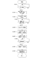
図5A、図5Bのフローチャート及び図6〜図11を参照して、本実施形態に係るデジタルカメラ100及び携帯電話150の動作を説明する。図5A、図5Bのフローチャート開始時点のデジタルカメラ100と携帯電話150との接続形態は、図4(a)に示す形態とする。
<Description of operation>
With reference to the flowcharts of FIGS. 5A and 5B and FIGS. 6 to 11, operations of the digital camera 100 and the mobile phone 150 according to the present embodiment will be described. The connection form between the digital camera 100 and the mobile phone 150 at the start of the flowcharts of FIGS. 5A and 5B is the form shown in FIG.

図5Aのフローチャートを参照して、デジタルカメラ100の動作について詳細に説明する。図5Aは、デジタルカメラ100の通信処理に関わるフローチャートである。本フローチャートは、撮影処理やGUI処理と並行してバックグラウンドで実行される。
ステップS501で、CPU101は近接無線通信部111の状態を監視し、近接無線通信部111が携帯電話150の近接無線通信部158と通信可能か否かを判定する。具体的には、デジタルカメラ100の近接無線通信エリア209と携帯電話150の近接無線通信エリア305とが十分接近したときに近接無線通信部111は通信可能となる。通信可能である場合、ステップS502に進む。
The operation of the digital camera 100 will be described in detail with reference to the flowchart of FIG. 5A. FIG. 5A is a flowchart relating to communication processing of the digital camera 100. This flowchart is executed in the background in parallel with the photographing process and the GUI process.
In step S <b> 501, the CPU 101 monitors the state of the proximity wireless communication unit 111 and determines whether the proximity wireless communication unit 111 can communicate with the proximity wireless communication unit 158 of the mobile phone 150. Specifically, the close proximity wireless communication unit 111 can communicate when the close proximity wireless communication area 209 of the digital camera 100 and the close proximity wireless communication area 305 of the mobile phone 150 are sufficiently close. If communication is possible, the process proceeds to step S502.

ステップS502で、CPU101は近接無線通信部111を用いて、無線LAN部112と無線LAN部159との間で通信するための各種パラメータを送信する。本ステップで送信するデータは、後述するステップS552で携帯電話150により受信される。
図6は、ステップS502で送信するデータを模式的に表す図である。
601は、デジタルカメラ100の無線LAN部112がアクセスポイントとして動作するときの、そのアクセスポイントのSSID(Service Set Identifier)である。
602は、無線LAN部112に接続する際に利用される認証・暗号化方式である。WPA2‐PSK(TKIP)の他にWEP等が用いられる。
603は、認証・暗号化方式602で示した暗号化方式で用いるパスフレーズである。
604は、携帯電話150の無線LAN部159に割り当てるべきIPアドレスである。
605は、携帯電話150の無線LAN部159に設定するネットマスクの値である。
606は、携帯電話150の無線LAN部159に設定するデフォルトのゲートウェイのIPアドレスである。
607は、デジタルカメラ100の無線LAN部112に割り当てられているIPアドレスである。図6のデータを受信した携帯電話150(後述するステップS552で受信する)は、IPアドレス607を用いることでデジタルカメラ100と通信を行うことができる。
In step S <b> 502, the CPU 101 transmits various parameters for communication between the wireless LAN unit 112 and the wireless LAN unit 159 using the close proximity wireless communication unit 111. The data transmitted in this step is received by the mobile phone 150 in step S552 described later.
FIG. 6 is a diagram schematically illustrating the data transmitted in step S502.
Reference numeral 601 denotes an SSID (Service Set Identifier) of the access point when the wireless LAN unit 112 of the digital camera 100 operates as an access point.
Reference numeral 602 denotes an authentication / encryption method used when connecting to the wireless LAN unit 112. WEP or the like is used in addition to WPA2-PSK (TKIP).
Reference numeral 603 denotes a passphrase used in the encryption method indicated by the authentication / encryption method 602.
Reference numeral 604 denotes an IP address to be assigned to the wireless LAN unit 159 of the mobile phone 150.
Reference numeral 605 denotes a netmask value set in the wireless LAN unit 159 of the mobile phone 150.
Reference numeral 606 denotes a default gateway IP address set in the wireless LAN unit 159 of the mobile phone 150.
Reference numeral 607 denotes an IP address assigned to the wireless LAN unit 112 of the digital camera 100. The mobile phone 150 that has received the data of FIG. 6 (received in step S552 described later) can communicate with the digital camera 100 by using the IP address 607.

図5Aに戻り、ステップS503で、CPU101は近接無線通信部111を介して、携帯電話150におけるアプリケーションの動作状況の取得を試みる。本ステップで受信するデータは、後述するステップS553で、携帯電話150が送信するデータである。なお、NFCの通信状態においては、本ステップで、携帯電話150におけるアプリケーションの動作状態を取得できない場合もありうる。   Returning to FIG. 5A, in step S <b> 503, the CPU 101 attempts to acquire the operation status of the application in the mobile phone 150 via the proximity wireless communication unit 111. The data received in this step is data transmitted by the mobile phone 150 in step S553 described later. Note that in the NFC communication state, the operation state of the application in the mobile phone 150 may not be acquired in this step.

ステップS503で受信するデータについて図7及び図8を用いて説明する。
図7は、携帯電話150の表示部154に表示される画面の内容を説明する図である。
図7(a)は、携帯電話150で動作しているアプリケーションにより、表示部154に表示される画面である。ここで動作しているアプリケーションは、日記を入力するためのアプリケーションである。
701は、カレンダーアイコンである。ユーザがこのアイコン701にタッチすると、図示しない日時選択画面が表示され、ユーザは入力する日記の日時を選択することができる。
702は、入力する日記の日時を表示するエリアである。カレンダーアイコン701で選択した日時が表示される。この日時は現在の日時でもよいし、過去の日時でもよい。
703は、テキストを入力するためのアイコンのエリアである。ユーザは入力したい文字に関連するアイコンをタッチ或いはフリックすることにより順次文字を入力する。
704は、日記入力エリアである。ユーザは、アイコン703を用いて、日記として記録したい文字列を本エリアに入力する。
705は、日記に静止画を添付するためのカメラアイコンである。ユーザがこのアイコン705にタッチすると、図7(b)に示すように画面が切り替わり、外部のデジタルカメラから日記用の静止画データを取得するための状態となる。
706は、日記に動画を添付するためのビデオアイコンである。ユーザがこのアイコン706にタッチすると、画面は外部のビデオカメラから日記用の動画データを取得するための状態となる。
707は、入力した日記を保存するためのセーブアイコンである。ユーザがこのアイコン707にタッチすると、日記入力エリア704に入力した文字列、アイコン705で選択した静止画データ、アイコン706で選択した動画データを、アイコン701で選択した日時に対する日記として保存する。
図7(b)は、日記用の静止画データを取得するために表示部154に表示される画面である。
708は、デジタルカメラ100と携帯電話150とを接近させ、近接無線通信により通信可能な状態とすることを促すためのグラフィクスである。
709は、日記用の静止画データの取得を中止するためのアイコンである。ユーザがこのアイコン709にタッチすると、図7(a)の画面表示に戻る。
Data received in step S503 will be described with reference to FIGS.
FIG. 7 is a diagram for explaining the contents of the screen displayed on the display unit 154 of the mobile phone 150.
FIG. 7A shows a screen displayed on the display unit 154 by an application operating on the mobile phone 150. The application operating here is an application for inputting a diary.
Reference numeral 701 denotes a calendar icon. When the user touches this icon 701, a date / time selection screen (not shown) is displayed, and the user can select the date / time of the diary to be input.
Reference numeral 702 denotes an area for displaying the date and time of the input diary. The date and time selected with the calendar icon 701 is displayed. This date may be the current date or a past date.
Reference numeral 703 denotes an icon area for inputting text. The user sequentially inputs characters by touching or flicking an icon related to the character to be input.
Reference numeral 704 denotes a diary input area. The user uses the icon 703 to input a character string to be recorded as a diary in this area.
Reference numeral 705 denotes a camera icon for attaching a still image to the diary. When the user touches the icon 705, the screen is switched as shown in FIG. 7B, and a state for acquiring diary still image data from an external digital camera is entered.
Reference numeral 706 denotes a video icon for attaching a moving image to the diary. When the user touches this icon 706, the screen enters a state for acquiring moving image data for diary from an external video camera.
Reference numeral 707 denotes a save icon for saving the input diary. When the user touches this icon 707, the character string input in the diary input area 704, the still image data selected with the icon 705, and the moving image data selected with the icon 706 are saved as a diary for the date and time selected with the icon 701.
FIG. 7B is a screen displayed on the display unit 154 in order to acquire diary still image data.
Reference numeral 708 denotes graphics for urging the digital camera 100 and the mobile phone 150 to approach each other so that they can communicate with each other through close proximity wireless communication.
Reference numeral 709 denotes an icon for canceling acquisition of still image data for diary. When the user touches this icon 709, the screen display of FIG.

図8は、ステップS503でCPU101が取得するデータを模式的に表す図である。
801は、携帯電話150で動作しているアプリケーションの種別である。図7で示した日記入力アプリケーションの場合は「日記/ブログ」となる。
802は、携帯電話150で動作しているアプリケーション801が着目している日時(日付・時刻)である。図7(a)で示した例では、エリア702の日時となる。
803は、携帯電話150で動作しているアプリケーションが取得しようとしているデータの種別である。図7(a)のアイコン705をタッチした場合は「静止画」に、アイコン706をタッチした場合は「動画」となる。
FIG. 8 is a diagram schematically showing data acquired by the CPU 101 in step S503.
Reference numeral 801 denotes the type of application running on the mobile phone 150. In the case of the diary input application shown in FIG. 7, it is “diary / blog”.
Reference numeral 802 denotes a date and time (date / time) on which the application 801 operating on the mobile phone 150 is focused. In the example shown in FIG. 7A, the date / time of the area 702 is set.
Reference numeral 803 denotes the type of data that the application running on the mobile phone 150 is to acquire. When the icon 705 in FIG. 7A is touched, “still image” is displayed, and when the icon 706 is touched, “moving image” is displayed.

図5Aに戻り、ステップS504で、CPU101は無線LAN部112を利用するための初期化を開始する。一般に、無線LAN機能を初期化し使用可能な状態とするまでには数秒かかるため、図5AのフローチャートではCPU101は無線LAN部112の初期化の完了を待たず次のステップS505に進む。   Returning to FIG. 5A, in step S <b> 504, the CPU 101 starts initialization for using the wireless LAN unit 112. In general, since it takes several seconds to initialize the wireless LAN function and make it usable, the CPU 101 proceeds to the next step S505 without waiting for completion of initialization of the wireless LAN unit 112 in the flowchart of FIG. 5A.

ステップS505で、CPU101は、ステップS503で正常にアプリケーションの動作状況(図8)を取得できたか否かを判定する。正常に取得できている場合はステップS506に、取得に失敗している場合はステップS508に進む。   In step S505, the CPU 101 determines whether or not the operation status (FIG. 8) of the application has been normally acquired in step S503. If it has been successfully acquired, the process proceeds to step S506. If the acquisition has failed, the process proceeds to step S508.

ステップS506で、CPU101はステップS503で受信したデータに従って、記憶媒体107に格納されている映像データをソートするための条件を決定する。例えばステップS503で図8のデータを受信した場合は、CPU101は次のようにソート条件を決定する。
・データ種別803が「静止画データ」であるので、記憶媒体107内の静止画データのみを対象とする。
・アプリ種別801が「日記/ブログ」であるので、映像データの日付がユーザの選択にとって重要な要素と判断する。そして、日時802で指定された日時より過去の映像データを新しい順にソートし、その後、残った映像データ(すなわち指定された日時より新しい映像データ)を古い順にソートする。
日記として記録したい内容は、日記の日時の前に起こった事象であることが想定されるため、上記のようなソートを行うことにより、日記に関連した映像データが先頭に集まることが期待できる。
In step S506, the CPU 101 determines conditions for sorting the video data stored in the storage medium 107 according to the data received in step S503. For example, when the data of FIG. 8 is received in step S503, the CPU 101 determines the sort condition as follows.
Since the data type 803 is “still image data”, only the still image data in the storage medium 107 is targeted.
Since the application type 801 is “diary / blog”, it is determined that the date of the video data is an important factor for the user's selection. Then, the past video data from the date and time designated by the date and time 802 are sorted in the newest order, and then the remaining video data (that is, video data newer than the designated date and time) is sorted in the oldest order.
Since it is assumed that the content to be recorded as a diary is an event that occurred before the date and time of the diary, it is expected that video data related to the diary will be gathered at the top by performing the sort as described above.

ステップS507で、CPU101はステップS505で決定したソート条件に従って、映像データをソートする。
図9と図10(a)の例を参照して、ステップS506の動作について具体的に説明する。
図9は、記憶媒体107に格納されている映像データを示す図である。この例では、記憶媒体107に10個の映像データが格納されている。ステップS503で受信したデータが図8のデータであった場合、CPU101はまず静止画データであるデータ901、902、904、906、907、908、909をソート対象とする。次に、日時2012/06/15 18:33より過去のデータ901、902、904を新しい順にソートする。すなわち、データ904、902、901という順にソートする。最後に、残ったデータ906、907、908、909を古い順にソートする。すなわち、データ906、907、908、909という順にソートする。
図10(a)は、ソートした結果の映像データを示す図である。図10(a)に示すように、ソート結果はデータ904、902、901、906、907、908、909となる。なお、図10(a)に示す列1001についてはステップS513で説明する。
In step S507, the CPU 101 sorts the video data according to the sorting condition determined in step S505.
With reference to the example of FIG. 9 and FIG. 10A, the operation of step S506 will be specifically described.
FIG. 9 is a diagram showing video data stored in the storage medium 107. In this example, ten pieces of video data are stored in the storage medium 107. If the data received in step S503 is the data of FIG. 8, the CPU 101 first sets the data 901, 902, 904, 906, 907, 908, 909 as still image data to be sorted. Next, the past data 901, 902, and 904 are sorted in order from the newest date and time 2012/06/15 18:33. That is, the data is sorted in the order of data 904, 902, 901. Finally, the remaining data 906, 907, 908, 909 are sorted in the oldest order. That is, the data is sorted in the order of data 906, 907, 908, 909.
FIG. 10A is a diagram showing video data obtained as a result of sorting. As shown in FIG. 10A, the sorting result is data 904, 902, 901, 906, 907, 908, 909. Note that the column 1001 illustrated in FIG. 10A will be described in step S513.

図5Aに戻り、ステップS508で、CPU101は映像データを新しい順にソートする。
図10(b)は、ソートした結果の映像データを示す図である。図10(b)に示すように、ソート結果はデータ910、909、・・・、901という順になる。なお、図10(b)に示す列1001についてはステップS513で説明する。
Returning to FIG. 5A, in step S508, the CPU 101 sorts the video data in the newest order.
FIG. 10B is a diagram showing video data as a result of sorting. As shown in FIG. 10B, the sorting results are in the order of data 910, 909,. Note that the column 1001 illustrated in FIG. 10B will be described in step S513.

図5Aに戻り、ステップS509で、CPU101はステップS504で実行した無線LAN部112の初期化が完了するのを待つ。無線LAN部112の初期化が完了し、後述するステップS556の無線LAN部159の設定変更が完了すると、デジタルカメラ100と携帯電話150とは無線LANにより通信できるようになる。このとき、接続形態は、図4(b)に示す形態となる。   Returning to FIG. 5A, in step S509, the CPU 101 waits for the initialization of the wireless LAN unit 112 executed in step S504 to be completed. When the initialization of the wireless LAN unit 112 is completed and the setting change of the wireless LAN unit 159 in step S556 described later is completed, the digital camera 100 and the mobile phone 150 can communicate with each other via the wireless LAN. At this time, the connection form is as shown in FIG.

ステップS510で、CPU101は無線LAN部112で受信するデータを監視し、携帯電話150がPTP/IP(Picture Transfer Protocol Over IP)の接続を開始するのを待つ。   In step S510, the CPU 101 monitors data received by the wireless LAN unit 112 and waits for the mobile phone 150 to start a PTP / IP (Picture Transfer Protocol Over IP) connection.

ステップS511で、CPU101は無線LAN部112で受信したPTPのコマンドを解析し、受信したコマンドに応じた処理をステップS512〜S516で実行する。
ステップS512は、ステップS511でセッション開始コマンド(OpenSessionコマンド)を受信した場合の処理である。このコマンドに対して、CPU101は、以降のPTPコマンドを実行するための内部処理(例えば、内部メモリの確保や携帯電話150以外の機器からPTPコマンドを受け付けないようにする排他制御等)を行う。その後、CPU101は、無線LAN部112を介して携帯電話150にコマンドが正常に受け付けられたことを表すデータを送信する。本処理が完了するとステップS511に戻り、次のPTPコマンドを待つ。
ステップS513は、ステップS511で映像リスト取得コマンド(GetObjectHandlesコマンド)を受信した場合の処理である。このコマンドに対して、CPU101は、携帯電話150に送信する映像データに対してユニークな番号(ObjectHandle)を付与し、無線LAN部112を介してその番号のリストを携帯電話150に送信する。このとき、CPU101は、ステップS507或いはステップS508でソートした結果の順に、ObjectHandleを割り当てる(図10の列1001)。本処理が完了するとステップS511に戻り、次のPTPコマンドを待つ。
ステップS514は、ステップS511でサムネイル取得コマンド(GetThumbコマンド)を受信した場合の処理である。このコマンドにはサムネイルを取得したい映像データに対応したObjectHandleがパラメータとして付随する。CPU101は、図10の列1001を利用してObjectHandleから映像データを特定し、無線LAN部112を介してその映像データのサムネイルデータを携帯電話150に送信する。本処理が完了するとステップS511に戻り、次のPTPコマンドを待つ。
ステップS515は、ステップS511で映像データ取得コマンド(GetObjectコマンド)を受信した場合の処理である。このコマンドにはデータを取得したい映像データに対応したObjectHandleがパラメータとして付随する。CPU101は、図10の列1001を利用してObjectHandleから映像データを特定し、無線LAN部112を介してその映像データを携帯電話150に送信する。本処理が完了するとステップS511に戻り、次のPTPコマンドを待つ。
ステップS516は、ステップS511でセッション終了コマンド(CloseSessionコマンド)を受信した場合の処理である。このコマンドに対して、CPU101は、PTPコマンド実行のために使用したメモリ等のリソースを開放し、無線LAN部112を介して携帯電話150にコマンドが正常に受け付けられたことを表すデータを送信する。
In step S511, the CPU 101 analyzes the PTP command received by the wireless LAN unit 112, and executes processes corresponding to the received command in steps S512 to S516.
Step S512 is processing when a session start command (OpenSession command) is received in step S511. In response to this command, the CPU 101 performs internal processing for executing subsequent PTP commands (for example, securing an internal memory or exclusive control for preventing a PTP command from being received from a device other than the mobile phone 150). Thereafter, the CPU 101 transmits data indicating that the command has been normally received to the mobile phone 150 via the wireless LAN unit 112. When this process is completed, the process returns to step S511 to wait for the next PTP command.
Step S513 is processing when the video list acquisition command (GetObjectHandles command) is received in step S511. In response to this command, the CPU 101 assigns a unique number (ObjectHandle) to the video data to be transmitted to the mobile phone 150, and transmits a list of the numbers to the mobile phone 150 via the wireless LAN unit 112. At this time, the CPU 101 assigns ObjectHandles in the order of the results sorted in step S507 or step S508 (column 1001 in FIG. 10). When this process is completed, the process returns to step S511 to wait for the next PTP command.
Step S514 is processing when a thumbnail acquisition command (GetThumb command) is received in step S511. This command is accompanied by an ObjectHandle corresponding to video data for which a thumbnail is to be acquired as a parameter. The CPU 101 identifies video data from the ObjectHandle using the column 1001 in FIG. 10 and transmits thumbnail data of the video data to the mobile phone 150 via the wireless LAN unit 112. When this process is completed, the process returns to step S511 to wait for the next PTP command.
Step S515 is processing when a video data acquisition command (GetObject command) is received in step S511. This command is accompanied by an ObjectHandle corresponding to the video data whose data is to be acquired as a parameter. The CPU 101 identifies video data from the ObjectHandle using the column 1001 in FIG. 10 and transmits the video data to the mobile phone 150 via the wireless LAN unit 112. When this process is completed, the process returns to step S511 to wait for the next PTP command.
Step S516 is processing when a session end command (CloseSession command) is received in step S511. In response to this command, the CPU 101 releases resources such as memory used for executing the PTP command, and transmits data indicating that the command has been normally received to the mobile phone 150 via the wireless LAN unit 112. .

ステップS517で、CPU101は無線LAN部112を無効にし、本フローチャートを終了する。
なお、CPU101はステップS511〜ステップS516で説明したPTPコマンド以外も処理可能であるが、本発明には直接関係しないので説明からは除外する。
In step S517, the CPU 101 invalidates the wireless LAN unit 112 and ends this flowchart.
The CPU 101 can process other than the PTP commands described in steps S511 to S516, but is excluded from the description because it is not directly related to the present invention.

次に、図5Bのフローチャートを参照して、携帯電話150の動作について詳細に説明する。
ステップS551で、CPU151は近接無線通信部158の状態を監視し、近接無線通信部158がデジタルカメラ100の近接無線通信部111と通信可能な状態か否かを判定する。具体的には、デジタルカメラ100の近接無線通信エリア209と携帯電話150の近接無線通信エリア305とが十分接近したときに近接無線通信部158は通信可能となる。通信可能である場合、ステップS552に進む。本ステップはステップS501に対応している。
Next, the operation of the mobile phone 150 will be described in detail with reference to the flowchart of FIG. 5B.
In step S <b> 551, the CPU 151 monitors the state of the close proximity wireless communication unit 158 and determines whether the close proximity wireless communication unit 158 is communicable with the close proximity wireless communication unit 111 of the digital camera 100. Specifically, the close proximity wireless communication unit 158 can communicate when the close proximity wireless communication area 209 of the digital camera 100 and the close proximity wireless communication area 305 of the mobile phone 150 are sufficiently close. If communication is possible, the process proceeds to step S552. This step corresponds to step S501.

ステップS552で、CPU151は近接無線通信部158を用いて、無線LAN部112と無線LAN部159との間で通信するための各種パラメータ(図6)を受信する。本ステップで受信するデータは、ステップS502でデジタルカメラ100により送信される。   In step S <b> 552, the CPU 151 receives various parameters (FIG. 6) for communicating between the wireless LAN unit 112 and the wireless LAN unit 159 using the close proximity wireless communication unit 158. The data received in this step is transmitted by the digital camera 100 in step S502.

ステップS553で、CPU151は近接無線通信部158を用いて、携帯電話150におけるアプリケーションの動作状況(図8)を送信する。本ステップで送信するデータは、ステップS503でデジタルカメラ100により受信される。   In step S <b> 553, the CPU 151 transmits the operation status (FIG. 8) of the application in the mobile phone 150 using the proximity wireless communication unit 158. The data transmitted in this step is received by the digital camera 100 in step S503.

ステップS554で、CPU151は現在の携帯電話150の通信設定をメモリ152に保存する。保存する情報は、3G通信部157によるデータ通信が有効になっているか否か、無線LAN部159によるデータ通信が有効になっているか否か、無線LAN部159で使用しているSSID、暗号化方式、パスフレーズ等である。   In step S554, CPU 151 stores the current communication settings of mobile phone 150 in memory 152. Information to be stored includes whether or not data communication by the 3G communication unit 157 is enabled, whether or not data communication by the wireless LAN unit 159 is enabled, the SSID used in the wireless LAN unit 159, and encryption System, passphrase, etc.

ステップS555で、CPU151はステップS552で受信した通信パラメータに従って無線LAN部159の設定を変更する。
ステップS556で、CPU151はステップS555で実施した無線LAN部159の設定変更が完了するのを待つ。
In step S555, the CPU 151 changes the setting of the wireless LAN unit 159 according to the communication parameter received in step S552.
In step S556, the CPU 151 waits for the setting change of the wireless LAN unit 159 performed in step S555 to be completed.

ステップS557で、CPU151は無線LAN部159を用いてデジタルカメラ100と通信し、PTP/IPによる接続を開始する。本ステップで送信するPTP/IP接続開始要求は、ステップS510でデジタルカメラ100により処理される。
ステップS558で、CPU151は無線LAN部159を用いてセッション開始コマンド(OpenSessionコマンド)を送信し、デジタルカメラ100がPTPコマンドを処理できる状態にする。本ステップで送信するコマンドはステップS511でデジタルカメラ100により受信され、本ステップで受信するレスポンスはステップS512でデジタルカメラ100により送信される。
In step S557, the CPU 151 communicates with the digital camera 100 using the wireless LAN unit 159 and starts a connection using PTP / IP. The PTP / IP connection start request transmitted in this step is processed by the digital camera 100 in step S510.
In step S558, the CPU 151 transmits a session start command (OpenSession command) using the wireless LAN unit 159 so that the digital camera 100 can process the PTP command. The command transmitted in this step is received by the digital camera 100 in step S511, and the response received in this step is transmitted by the digital camera 100 in step S512.

ステップS559で、CPU151は無線LAN部159を用いて映像リスト取得コマンド(GetObjectHandlesコマンド)を送信する。CPU151は無線LAN部159で受信するレスポンスから、デジタルカメラ100から取得可能な映像データのObjectHandleのリスト(図10の列1001)を取得する。本ステップで送信するコマンドはステップS511でデジタルカメラ100により受信され、本ステップで受信するレスポンスはステップS513でデジタルカメラ100により送信される。   In step S559, the CPU 151 transmits a video list acquisition command (GetObjectHandles command) using the wireless LAN unit 159. The CPU 151 obtains an object handle list (column 1001 in FIG. 10) of video data that can be obtained from the digital camera 100 from the response received by the wireless LAN unit 159. The command transmitted in this step is received by the digital camera 100 in step S511, and the response received in this step is transmitted by the digital camera 100 in step S513.

ステップS560で、CPU151はステップS559で取得したObjectHandleを順次指定しながら、無線LAN部159を用いてサムネイル取得コマンド(GetThumbコマンド)を送信する。CPU151は、無線LAN部159で受信するレスポンスからObjectHandleで指定した映像のサムネイルデータを取得する。本ステップで送信するコマンドはステップS511でデジタルカメラ100により受信され、本ステップで受信するレスポンスはステップS514でデジタルカメラ100により送信される。
ステップS561で、CPU151はステップS560で取得したサムネイルデータを、GUIとして表示部154にタイル状に並べて表示する。表示部154に表示されるGUIについては後述する。
In step S560, the CPU 151 transmits a thumbnail acquisition command (GetThumb command) using the wireless LAN unit 159 while sequentially specifying the ObjectHandles acquired in step S559. The CPU 151 acquires the thumbnail data of the video specified by the ObjectHandle from the response received by the wireless LAN unit 159. The command transmitted in this step is received by the digital camera 100 in step S511, and the response received in this step is transmitted by the digital camera 100 in step S514.
In step S561, the CPU 151 displays the thumbnail data acquired in step S560 in a tiled manner on the display unit 154 as a GUI. The GUI displayed on the display unit 154 will be described later.

ステップS562で、CPU151は、ステップS559で取得した全てのObjectHandleについてステップS561の処理を実行したか否かを判定する。全てを実行した場合はステップS563に進み、未実行のObjectHandleが存在する場合にはステップS560に戻る。図11は、ステップS560〜S562の処理による表示部154におけるサムネイルデータ表示の例である。CPU151はステップS560で取得したサムネイルデータを左上から右下にタイル状に並べて表示することで、ユーザはデジタルカメラ100の映像を俯瞰することができる。また、ステップS559で取得した映像リストの順に表示することで、ユーザが着目しやすい左上の位置に表示されるサムネイルデータは、映像リストの先頭に位置する映像のサムネイルになる。すなわち、ステップS507或いはステップS508で実行されたソート結果の上位の映像がサムネイルの左上に配置されることになる。   In step S562, the CPU 151 determines whether or not the process of step S561 has been executed for all the ObjectHandles acquired in step S559. If all have been executed, the process proceeds to step S563, and if there is an unexecuted ObjectHandle, the process returns to step S560. FIG. 11 is an example of thumbnail data display on the display unit 154 by the processing of steps S560 to S562. The CPU 151 displays the thumbnail data acquired in step S560 in a tile shape from the upper left to the lower right, so that the user can look down on the video of the digital camera 100. Further, by displaying in the order of the video list acquired in step S559, the thumbnail data displayed at the upper left position that is easy for the user to focus on becomes the thumbnail of the video positioned at the top of the video list. That is, the upper video of the sorting result executed in step S507 or step S508 is arranged at the upper left of the thumbnail.

図5Bに戻り、ステップS563で、CPU151は操作部155を利用して図11のサムネイルのいずれかがタッチされたか否かを判定する。いずれかのサムネイルデータが選択された場合にはステップS564に進む。   Returning to FIG. 5B, in step S563, the CPU 151 determines whether any of the thumbnails of FIG. 11 is touched using the operation unit 155. If any thumbnail data is selected, the process proceeds to step S564.

ステップS564で、CPU151はステップS563で選択されたサムネイルデータのObjectHandleを指定しながら、無線LAN部159を用いて映像データ取得コマンド(GetObjectコマンド)を送信する。CPU151は、無線LAN部159で受信するレスポンスからObjectHandleで指定した映像のデータを取得する。本ステップで送信するコマンドはステップS511でデジタルカメラ100により受信され、本ステップで受信するレスポンスはステップS515でデジタルカメラ100により送信される。   In step S564, the CPU 151 transmits a video data acquisition command (GetObject command) using the wireless LAN unit 159 while designating the ObjectHandle of the thumbnail data selected in step S563. The CPU 151 acquires video data specified by the ObjectHandle from the response received by the wireless LAN unit 159. The command transmitted in this step is received by the digital camera 100 in step S511, and the response received in this step is transmitted by the digital camera 100 in step S515.

ステップS565で、CPU151は無線LAN部159を用いて通信終了コマンド(CloseSessionコマンド)を送信し、無線LAN部159で受信するレスポンスから正常に通信が完了したことを確認する。本ステップで送信するコマンドはステップS511でデジタルカメラ100により受信され、本ステップで受信するレスポンスはステップS516でデジタルカメラ100により送信される。   In step S <b> 565, the CPU 151 transmits a communication end command (Close Session command) using the wireless LAN unit 159, and confirms that communication has been completed normally from the response received by the wireless LAN unit 159. The command transmitted in this step is received by the digital camera 100 in step S511, and the response received in this step is transmitted by the digital camera 100 in step S516.

ステップS566で、CPU151はステップS554で保存した通信設定を復帰させる。このとき、接続形態は図4(a)に示す形態となる。
なお、CPU151はステップS558〜ステップS565で説明したPTPコマンド以外も実行可能であるが、本発明には直接関係しないので説明からは除外する。
In step S566, the CPU 151 restores the communication setting saved in step S554. At this time, the connection form is as shown in FIG.
The CPU 151 can execute other than the PTP command described in steps S558 to S565, but is excluded from the description because it is not directly related to the present invention.

以上述べたように、複数のデータを保持しているデジタルカメラ100において、データの送信前にあらかじめ取得した情報に基づきデータをソートすることにより、データ選択の手間を軽減することができる。   As described above, in the digital camera 100 that holds a plurality of data, it is possible to reduce the labor of data selection by sorting the data based on information acquired in advance before data transmission.

(第2の実施形態)
第2の実施形態でも、第1の実施形態と同様、本発明のデータ処理装置をNFCと無線LAN機能を有するデジタルカメラとした例を説明する。本実施形態では、データ処理装置が扱うデータを映像データ(静止画又は動画)とし、データ処理装置と通信しうる装置を、NFCと無線LAN機能を有する携帯電話(スマートフォン)とする。
<装置説明>
本実施形態でも、第1の実施形態と同様のデジタルカメラ100と携帯電話150により構成されるため、その説明を省略する。図2〜図3、図4(a)についても、第1の実施形態と同様である。
図4(c)について説明する。図4(c)は、携帯電話150が無線LANのアクセスポイントとなり、デジタルカメラ100が無線LANクライアントとして携帯電話150に接続している状態を示す図である。したがって、デジタルカメラ100と携帯電話150とは通信を行うことができる。携帯電話150は無線LANアクセスポイントとしての通信と3Gによるデータ通信とを同時に行うことができるので、この状態では携帯電話150は移動体通信網170へのデータ通信も行うことができる。
(Second Embodiment)
In the second embodiment, as in the first embodiment, an example in which the data processing apparatus of the present invention is a digital camera having NFC and a wireless LAN function will be described. In this embodiment, data handled by the data processing device is video data (still image or moving image), and a device that can communicate with the data processing device is a mobile phone (smart phone) having NFC and a wireless LAN function.
<Device description>
In this embodiment, the digital camera 100 and the mobile phone 150 are the same as those in the first embodiment, and thus the description thereof is omitted. 2 to 3 and 4A are the same as those in the first embodiment.
FIG. 4C will be described. FIG. 4C is a diagram illustrating a state in which the mobile phone 150 serves as a wireless LAN access point and the digital camera 100 is connected to the mobile phone 150 as a wireless LAN client. Therefore, the digital camera 100 and the mobile phone 150 can communicate. Since the mobile phone 150 can simultaneously perform communication as a wireless LAN access point and 3G data communication, the mobile phone 150 can also perform data communication to the mobile communication network 170 in this state.

<動作説明>
図12A、図12Bのフローチャート及び図13〜図18を参照して、本実施形態に係るデジタルカメラ100及び携帯電話150の動作を説明する。図12A、図12Bのフローチャート開始時点のデジタルカメラ100と携帯電話150との接続形態は、図4(a)に示す形態とする。
<Description of operation>
The operations of the digital camera 100 and the mobile phone 150 according to the present embodiment will be described with reference to the flowcharts of FIGS. 12A and 12B and FIGS. 13 to 18. The connection form between the digital camera 100 and the mobile phone 150 at the start of the flowcharts of FIGS. 12A and 12B is the form shown in FIG.

図12Aのフローチャートを参照して、デジタルカメラ100の動作について詳細に説明する。図12Aは、デジタルカメラ100の通信処理に関わるフローチャートである。本フローチャートは、撮影処理やGUI処理と並行してバックグラウンドで実行される。
ステップS1201で、CPU101は近接無線通信部111の状態を監視し、近接無線通信部111が携帯電話150の近接無線通信部158と通信可能か否かを判定する。具体的には、デジタルカメラ100の近接無線通信エリア209と携帯電話150の近接無線通信エリア305とが十分接近したときに近接無線通信部111は通信可能となる。通信可能である場合、ステップS1202に進む。
The operation of the digital camera 100 will be described in detail with reference to the flowchart of FIG. 12A. FIG. 12A is a flowchart relating to communication processing of the digital camera 100. This flowchart is executed in the background in parallel with the photographing process and the GUI process.
In step S <b> 1201, the CPU 101 monitors the state of the proximity wireless communication unit 111 and determines whether the proximity wireless communication unit 111 can communicate with the proximity wireless communication unit 158 of the mobile phone 150. Specifically, the close proximity wireless communication unit 111 can communicate when the close proximity wireless communication area 209 of the digital camera 100 and the close proximity wireless communication area 305 of the mobile phone 150 are sufficiently close. If communication is possible, the process proceeds to step S1202.

ステップS1202で、CPU101は近接無線通信部111を用いて、無線LAN部112と無線LAN部159との間で通信するための各種パラメータと、携帯電話150におけるアプリケーションの動作状況を取得する。本ステップで受信するデータは、後述するステップS1252で携帯電話150により送信される。   In step S <b> 1202, the CPU 101 uses the proximity wireless communication unit 111 to acquire various parameters for communication between the wireless LAN unit 112 and the wireless LAN unit 159 and the operation status of the application in the mobile phone 150. The data received in this step is transmitted by the mobile phone 150 in step S1252, which will be described later.

ステップS1202で受信するデータについて図13及び図14を用いて説明する。
図13は、携帯電話150の表示部154に表示される画面の内容を説明する図である。
図13(a)は、携帯電話150で動作しているアプリケーションにより、表示部154に表示される画面である。ここで動作しているアプリケーションは、ユーザが訪問した地点を記録する(チェックインする)ためのアプリケーションである。
1301は、地図アイコンである。ユーザがこのアイコン1301にタッチすると、図示しない地図が表示され、ユーザは記録したい地点(現在位置や過去に訪問したことのある場所)を選択することができる。
1302は、チェックインする地点の名称(地点名)を表示するエリアである。地図アイコン1301で選択した地点名が表示される。
1303は、テキストを入力するためのアイコンのエリアである。ユーザは入力したい文字に関連するアイコンをタッチ或いはフリックすることにより順次文字を入力する。
1304は、コメントエリアである。ユーザは、アイコン1303を用いて、チェックインとともに記録したい文字列を本エリアに入力する。
1305は、チェックインに静止画を添付するためのカメラアイコンである。ユーザがこのアイコン1305にタッチすると、図13(b)に示すように画面が切り替わり、外部のデジタルカメラからチェックインの静止画データを取得するための状態となる。
1306は、チェックインに動画を添付するためのビデオアイコンである。ユーザがこのアイコン1306にタッチすると、画面は外部のビデオカメラからチェックイン用の動画データを取得するための状態となる。
1307は、選択した地点にチェックインするためのアイコンである。ユーザがこのアイコン1307にタッチすると、コメントエリア1304に入力した文字列、アイコン1305で選択した静止画データ、アイコン1306で選択した動画データを、アイコン1301で選択した地点へのチェックインとして保存する。
図13(b)は、チェックイン用の静止画データを取得するために表示部154に表示される画面である。
1308は、デジタルカメラと携帯電話とを接近させ近接無線通信により通信可能な状態とすることを促すためのグラフィクスである。
1309は、チェックイン用の静止画データの取得を中止するためのアイコンである。ユーザがこのアイコン1309にタッチすると、図13(a)の画面表示に戻る。
Data received in step S1202 will be described with reference to FIGS.
FIG. 13 is a diagram for explaining the contents of the screen displayed on the display unit 154 of the mobile phone 150.
FIG. 13A is a screen displayed on the display unit 154 by an application running on the mobile phone 150. The application operating here is an application for recording (checking in) a point visited by the user.
Reference numeral 1301 denotes a map icon. When the user touches this icon 1301, a map (not shown) is displayed, and the user can select a point (current position or a place visited in the past) to be recorded.
Reference numeral 1302 denotes an area for displaying the name (point name) of the check-in point. The name of the spot selected with the map icon 1301 is displayed.
Reference numeral 1303 denotes an icon area for inputting text. The user sequentially inputs characters by touching or flicking an icon related to the character to be input.
Reference numeral 1304 denotes a comment area. The user uses the icon 1303 to input a character string to be recorded together with check-in in this area.
Reference numeral 1305 denotes a camera icon for attaching a still image to check-in. When the user touches this icon 1305, the screen is switched as shown in FIG. 13B, and a state for acquiring still image data of check-in from an external digital camera is obtained.
Reference numeral 1306 denotes a video icon for attaching a moving image to check-in. When the user touches this icon 1306, the screen is in a state for acquiring moving-in data for check-in from an external video camera.
Reference numeral 1307 denotes an icon for checking in to the selected point. When the user touches this icon 1307, the character string input in the comment area 1304, the still image data selected with the icon 1305, and the moving image data selected with the icon 1306 are stored as a check-in to the location selected with the icon 1301.
FIG. 13B is a screen displayed on the display unit 154 in order to acquire still image data for check-in.
Reference numeral 1308 denotes graphics for urging the digital camera and the mobile phone to approach each other so that they can communicate with each other through close proximity wireless communication.
Reference numeral 1309 denotes an icon for canceling acquisition of still image data for check-in. When the user touches this icon 1309, the screen display of FIG.

図14は、ステップS1202でCPU101が取得するデータを模式的に表す図である。
1401〜1407は無線LAN部112と無線LAN部159との間で通信するための各種パラメータであり、1408〜1412は携帯電話150におけるアプリケーションの動作状況である。
1401は、携帯電話150の無線LAN部159がアクセスポイントとして動作するときの、そのアクセスポイントのSSIDである。
1402は、無線LAN部159に接続する際に利用される認証・暗号化方式である。WPA2ーPSK(TKIP)の他にWEP等が用いられる。
1403は、認証・暗号化方式1402で示した暗号化方式で用いるパスフレーズである。
1404は、デジタルカメラ100の無線LAN部112に割り当てるべきIPアドレスである。
1405は、デジタルカメラ100の無線LAN部112に設定するネットマスクの値である。
1406は、デジタルカメラ100の無線LAN部112に設定するデフォルトのゲートウェイのIPアドレスである。
1407は、携帯電話150の無線LAN部159に割り当てられているIPアドレスである。図14のデータを受信したデジタルカメラ100は、IPアドレス1407を用いることで携帯電話150と通信を行うことができる。
1408は、携帯電話150で動作しているアプリケーションの種別である。図13で示したチェックインアプリケーションの場合は「ロケーション」となる。
1409は、携帯電話150で動作しているアプリケーション1408が着目している地点情報である。図13(a)で示した例では、地点名1302の緯度経度である。
1410は、携帯電話150で動作しているアプリケーションが取得しようとしているデータの種別である。図13(a)のアイコン1305をタッチした場合は「静止画」に、アイコン1306をタッチした場合は「動画」となる。
FIG. 14 is a diagram schematically illustrating data acquired by the CPU 101 in step S1202.
1401 to 1407 are various parameters for communication between the wireless LAN unit 112 and the wireless LAN unit 159, and 1408 to 1412 are operation states of applications in the mobile phone 150.
Reference numeral 1401 denotes the SSID of the access point when the wireless LAN unit 159 of the mobile phone 150 operates as an access point.
Reference numeral 1402 denotes an authentication / encryption method used when connecting to the wireless LAN unit 159. WEP or the like is used in addition to WPA2-PSK (TKIP).
Reference numeral 1403 denotes a passphrase used in the encryption method indicated by the authentication / encryption method 1402.
Reference numeral 1404 denotes an IP address to be assigned to the wireless LAN unit 112 of the digital camera 100.
Reference numeral 1405 denotes a netmask value set in the wireless LAN unit 112 of the digital camera 100.
Reference numeral 1406 denotes an IP address of a default gateway set in the wireless LAN unit 112 of the digital camera 100.
Reference numeral 1407 denotes an IP address assigned to the wireless LAN unit 159 of the mobile phone 150. The digital camera 100 that has received the data in FIG. 14 can communicate with the mobile phone 150 by using the IP address 1407.
Reference numeral 1408 denotes the type of application running on the mobile phone 150. In the case of the check-in application shown in FIG.
Reference numeral 1409 denotes point information focused on by the application 1408 operating on the mobile phone 150. In the example illustrated in FIG. 13A, the latitude / longitude of the spot name 1302.
Reference numeral 1410 denotes the type of data that the application running on the mobile phone 150 is trying to acquire. When the icon 1305 in FIG. 13A is touched, “still image” is displayed, and when the icon 1306 is touched, “moving image” is displayed.

図12Aに戻り、ステップS1203で、CPU101は無線LAN部112を利用するための初期化を開始する。一般に、無線LAN機能を初期化し使用可能な状態とするまでには数秒かかるため、図12AのフローチャートではCPU101は無線LAN部112の初期化の完了を待たず次のステップS1204に進む。   Returning to FIG. 12A, in step S <b> 1203, the CPU 101 starts initialization for using the wireless LAN unit 112. In general, since it takes several seconds to initialize the wireless LAN function and make it usable, the CPU 101 proceeds to the next step S1204 without waiting for the completion of the initialization of the wireless LAN unit 112 in the flowchart of FIG. 12A.

ステップS1204で、CPU101はステップS1202で受信したデータに従って、記憶媒体107に格納されている映像データをソートするための条件を決定する。例えばステップS1202で図14のデータを受信した場合は、CPU101は次のようにソート条件を決定する。
・データ種別1410が「静止画データ」であるので、記憶媒体107内の静止画データのみを対象とする。
・アプリ種別1408が「ロケーション」であるので、映像データの撮影場所がユーザの選択にとって重要な要素と判断する。そして、映像データのうち撮影場所情報を有する映像データのみ地点情報1409で指定された地点に近い順に映像データをソートする。
チェックインとして記録したい内容は、チェックインしようとしている場所に関連した事象であることが想定されるため、上記のソートを行うことにより、チェックイン場所に関連した映像データが先頭に集まることが期待できる。
In step S1204, the CPU 101 determines conditions for sorting the video data stored in the storage medium 107 according to the data received in step S1202. For example, when the data of FIG. 14 is received in step S1202, the CPU 101 determines the sort condition as follows.
Since the data type 1410 is “still image data”, only the still image data in the storage medium 107 is targeted.
Since the application type 1408 is “location”, it is determined that the shooting location of the video data is an important factor for the user's selection. Then, only the video data having the shooting location information among the video data is sorted in the order closer to the spot specified by the spot information 1409.
Since it is assumed that the content to be recorded as check-in is an event related to the location where the check-in is to be performed, it is expected that the video data related to the check-in location will be gathered at the top by performing the above sort. it can.

ステップS1205で、CPU101は記憶媒体107にステップS1204で決定したソート条件に対応する映像データが存在するか否かを判定する。ソート対象の映像データが存在する場合、ステップS1206に進み、存在しない場合、ステップS1207に進む。
図15の例を参照して、ステップS1205の動作について具体的に説明する。
図15(a)、(b)は、記憶媒体107に格納されている映像データを示す図である。
図15(a)の例では、記憶媒体107に10個の映像データが格納されている。ステップS1202で受信したデータが図14のデータであった場合、データ1501、1502、1504、1507、1509の5つが静止画データでありかつ撮影場所情報を有するので、ソートの対象とする。
一方、図15(b)の例では、記憶媒体107に5個の映像データが格納されている。データ1511、1512、1514の3つが静止画データであるが、撮影場所情報を有さないので、ソートの対象となる映像データは存在しないことになる。
In step S1205, the CPU 101 determines whether or not video data corresponding to the sort condition determined in step S1204 exists in the storage medium 107. If the sort target video data exists, the process proceeds to step S1206, and if not, the process proceeds to step S1207.
The operation in step S1205 will be specifically described with reference to the example in FIG.
FIGS. 15A and 15B are diagrams showing video data stored in the storage medium 107.
In the example of FIG. 15A, ten pieces of video data are stored in the storage medium 107. If the data received in step S1202 is the data of FIG. 14, the data 1501, 1502, 1504, 1507, and 1509 are still image data and have shooting location information, and are therefore subject to sorting.
On the other hand, in the example of FIG. 15B, five pieces of video data are stored in the storage medium 107. Three pieces of data 1511, 1512, and 1514 are still image data, but since there is no shooting location information, there is no video data to be sorted.

ステップS1206で、CPU101はステップS1204で決定したソート条件に従って映像データをソートする。
図15(a)と図16(a)の例を参照して、ステップS1206の動作について具体的に説明する。
上述のように図15(a)に示した映像データのうち、データ1501、1502、1504、1506、1507、1508、1509がソート対象である。CPU101は、ソート対象の映像データを、地点1409(北緯35.6400度、東経139.8622度)に近い順にソートする。すなわち、データ1507、1509、1501、1502、1504という順にソートする。
図16(a)は、ソートした結果の映像データを示す図である。図16(a)に示すように、ソート結果はデータ1507、1509、1501、1502、1504となる。
In step S1206, the CPU 101 sorts the video data according to the sorting condition determined in step S1204.
With reference to the example of FIG. 15A and FIG. 16A, the operation of step S1206 will be specifically described.
As described above, among the video data shown in FIG. 15A, data 1501, 1502, 1504, 1506, 1507, 1508, and 1509 are to be sorted. The CPU 101 sorts the video data to be sorted in the order closer to the point 1409 (35.6400 degrees north latitude, 1399.8622 degrees east longitude). That is, the data is sorted in the order of data 1507, 1509, 1501, 1502, 1504.
FIG. 16A is a diagram showing video data as a result of sorting. As shown in FIG. 16A, the sorting results are data 1507, 1509, 1501, 1502, 1504.

図12Aに戻り、ステップS1207で、CPU101は映像データを新しい順にソートする。
図15(b)と図16(b)の例を参照して、ステップS1207の動作について具体的に説明する。
図15(b)に示した映像データのうち、静止画であるデータ1511、1512、1514を新しい順にソートする。すなわち、データ1514、1512、1511という順にソートする。
図16(b)は、ソートした結果の映像データを示す図である。図16(b)に示すように、ソート結果はデータ1514、1512、1511となる。
Returning to FIG. 12A, in step S1207, the CPU 101 sorts the video data in the newest order.
With reference to the example of FIG.15 (b) and FIG.16 (b), the operation | movement of step S1207 is demonstrated concretely.
Among the video data shown in FIG. 15B, the data 1511, 1512, and 1514 which are still images are sorted in order from the newest. That is, the data is sorted in the order of data 1514, 1512, and 1511.
FIG. 16B is a diagram showing video data as a result of sorting. As shown in FIG. 16B, the sorting results are data 1514, 1512, and 1511.

図12Aに戻り、ステップS1208で、CPU101はソートの結果に従って、映像データの一覧表示を行うためのHTMLデータを生成する。なお、本実施形態では、所定のデータとしてHTMLデータを生成するとしたが、CSSデータやJavaScript(登録商標)データを生成するようにしてもよい。
図17(a)に、図16(a)のソート結果に対し、ステップS1208で生成したHTMLデータの例を示す。このHTMLデータでは、ソートした結果順に映像データのサムネイルデータが表示されるような内容となっている。すなわち、映像データ1507を表示するための記述が1701である。同様に、映像データ1509を表示するための記述が1702であり、映像データ1501を表示するための記述が1703であり、映像データ1502を表示するための記述が1704であり、映像データ1503を表示するための記述が1705である。
Returning to FIG. 12A, in step S1208, the CPU 101 generates HTML data for displaying a list of video data in accordance with the result of sorting. In the present embodiment, the HTML data is generated as the predetermined data. However, CSS data and JavaScript (registered trademark) data may be generated.
FIG. 17A shows an example of the HTML data generated in step S1208 with respect to the sorting result of FIG. The HTML data is such that the thumbnail data of the video data is displayed in the sorted order. That is, the description for displaying the video data 1507 is 1701. Similarly, the description for displaying the video data 1509 is 1702, the description for displaying the video data 1501 is 1703, the description for displaying the video data 1502 is 1704, and the video data 1503 is displayed. 1705 is a description for this.

図12Aに戻り、ステップS1209で、CPU101は、ステップS1208で生成したHTMLデータや映像データを外部に公開するために、Webサーバソフトウェアの動作を開始する。
ステップS1210で、CPU101はステップS1203で実行した無線LAN部112の初期化が完了するのを待つ。無線LAN部112の初期化が完了し、後述するステップS1254の無線LAN部159の設定変更が完了すると、デジタルカメラ100と携帯電話150とは無線LANにより通信できるようになる。このとき、接続形態は、図4(c)で示す形態となる。
ステップS1211で、CPU101はステップS1209で有効化したWebサーバソフトウェアに外部から接続があるのを待つ。
Returning to FIG. 12A, in step S1209, the CPU 101 starts the operation of the Web server software in order to publish the HTML data and video data generated in step S1208 to the outside.
In step S1210, the CPU 101 waits for the initialization of the wireless LAN unit 112 executed in step S1203 to be completed. When the initialization of the wireless LAN unit 112 is completed and the setting change of the wireless LAN unit 159 in step S1254, which will be described later, is completed, the digital camera 100 and the mobile phone 150 can communicate via the wireless LAN. At this time, the connection form is as shown in FIG.
In step S1211, the CPU 101 waits for external connection to the Web server software activated in step S1209.

ステップS1212で、CPU101はステップS1209で有効化したWebサーバソフトウェアに対して、HTMLデータや映像データのデータ取得要求(HTTP GETコマンド等)があるか否かを判定する。データ取得要求がある場合、ステップS1213に進み、データ取得要求がない場合、ステップS1214に進む。
ステップS1213で、CPU101はステップS1212で受信しデータ取得要求に応じて、ステップS1208で生成したHTMLデータや、記憶媒体107に保持されている映像データ等を返信する。データの返信が完了すると、ステップS1212に戻り、次のデータ取得要求を確認する。
一方、ステップS1214で、CPU101は無線LAN部112と無線LAN部159との間で引き続き通信が可能か否かを判定する。通信が不可能な場合(後述するステップS1260でアクセスポイント機能が無効化された場合)、本フローチャートを終了し、通信が可能な場合、ステップS1212に戻り、次のデータ取得要求を確認する。
In step S <b> 1212, the CPU 101 determines whether there is a data acquisition request (such as an HTTP GET command) for HTML data or video data for the Web server software activated in step S <b> 1209. If there is a data acquisition request, the process proceeds to step S1213. If there is no data acquisition request, the process proceeds to step S1214.
In step S1213, the CPU 101 returns the HTML data generated in step S1208, the video data held in the storage medium 107, and the like in response to the data acquisition request received in step S1212. When the data reply is completed, the process returns to step S1212 to confirm the next data acquisition request.
On the other hand, in step S <b> 1214, the CPU 101 determines whether communication can be continued between the wireless LAN unit 112 and the wireless LAN unit 159. If communication is impossible (when the access point function is disabled in step S1260 described later), this flowchart is terminated. If communication is possible, the process returns to step S1212 to confirm the next data acquisition request.

次に、図12Bのフローチャートを参照して、携帯電話150の動作について詳細に説明する。
ステップS1251で、CPU151は近接無線通信部158の状態を監視し、近接無線通信部158がデジタルカメラ100の近接無線通信部111と通信可能な状態か否かを判定する。具体的には、デジタルカメラ100の近接無線通信エリア209と携帯電話150の近接無線通信エリア305とが十分接近したときに近接無線通信部158は通信可能となる。通信可能である場合、ステップS552に進む。本ステップはステップS1201に対応している。
ステップS1252で、CPU151は近接無線通信部158を用いて、無線LAN部112と無線LAN部159との間で通信するための各種パラメータと、携帯電話150におけるアプリケーションの動作状況を送信する(図14)。本ステップで送信するデータは、ステップS1202でデジタルカメラ100により受信される。
Next, the operation of the mobile phone 150 will be described in detail with reference to the flowchart of FIG. 12B.
In step S <b> 1251, the CPU 151 monitors the state of the close proximity wireless communication unit 158, and determines whether the close proximity wireless communication unit 158 can communicate with the close proximity wireless communication unit 111 of the digital camera 100. Specifically, the close proximity wireless communication unit 158 can communicate when the close proximity wireless communication area 209 of the digital camera 100 and the close proximity wireless communication area 305 of the mobile phone 150 are sufficiently close. If communication is possible, the process proceeds to step S552. This step corresponds to step S1201.
In step S1252, the CPU 151 uses the proximity wireless communication unit 158 to transmit various parameters for communication between the wireless LAN unit 112 and the wireless LAN unit 159 and the operation status of the application in the mobile phone 150 (FIG. 14). ). The data transmitted in this step is received by the digital camera 100 in step S1202.

ステップS1253で、CPU151は無線LAN部159のアクセスポイント機能を有効化する。このとき、アクセスポイントで使用するSSID・暗号化種別・パスフレーズは図14の1401〜1403が用いられる。   In step S1253, the CPU 151 activates the access point function of the wireless LAN unit 159. At this time, 1401 to 1403 in FIG. 14 are used as the SSID, encryption type, and passphrase used at the access point.

ステップS1254で、無線LAN部159と無線LAN部112とが通信可能になるまで待つ。具体的には、ステップS1210が完了し、デジタルカメラ100と携帯電話150との接続形態が図4(c)の状態となった場合、ステップS1255に進む。   In step S1254, the process waits until the wireless LAN unit 159 and the wireless LAN unit 112 can communicate with each other. Specifically, when step S1210 is completed and the connection form between the digital camera 100 and the mobile phone 150 is in the state of FIG. 4C, the process proceeds to step S1255.

ステップS1255で、CPU151は無線LAN部159を用いてデジタルカメラ100と通信し、ステップS1209で起動したWebサーバソフトウェアに接続する。
ステップS1256で、CPU151は無線LAN部159を用いて、デジタルカメラ100からHTMLデータ(図17(a))とHTMLデータに関わる映像データ(サムネイルデータ)を取得する。
ステップS1257では、CPU151はステップS1256で取得したHTMLデータと映像データを表示部154に表示する(レンダリングする)。
図17(b)は、図17(a)のHTMLデータをレンダリングした結果である。HTMLデータの記述1701の部分が1706として、HTMLデータの記述1702の部分が1707として、HTMLデータの記述1703の部分が1708として、HTMLデータの記述1704の部分が1709として、HTMLデータの記述1705の部分が1710として表示される。
In step S1255, the CPU 151 communicates with the digital camera 100 using the wireless LAN unit 159, and connects to the Web server software activated in step S1209.
In step S1256, the CPU 151 uses the wireless LAN unit 159 to acquire HTML data (FIG. 17A) and video data (thumbnail data) related to the HTML data from the digital camera 100.
In step S1257, the CPU 151 displays (renders) the HTML data and video data acquired in step S1256 on the display unit 154.
FIG. 17B shows the result of rendering the HTML data of FIG. The HTML data description 1701 is 1706, the HTML data description 1702 is 1707, the HTML data description 1703 is 1708, the HTML data description 1704 is 1709, and the HTML data description 1705 The portion is displayed as 1710.

図12Bに戻り、ステップS1258で、CPU151は操作部155を利用して図17(b)の映像のいずれかがタッチされたか否かを判定する。いずれかのサムネイルデータが選択された場合、ステップS1259に進む。
ステップS1259で、CPU151は無線LAN部159を用いてデジタルカメラ100からステップS1258で選択された映像を取得する。例えば図17(b)において映像1706が選択された場合、対応するHTMLデータの記述1701に基づき、映像データIMG_0007.JPGの取得を要求し、ステップS1213でデジタルカメラ100により送信される映像データを取得する。
ステップS1260で、CPU151はステップS1253で有効化したアクセスポイント機能を無効化し、本フローチャートを終了する。これにより、デジタルカメラ100と携帯電話150との間の通信は終了する。
Returning to FIG. 12B, in step S <b> 1258, the CPU 151 determines whether any of the images in FIG. 17B is touched using the operation unit 155. If any thumbnail data is selected, the process advances to step S1259.
In step S1259, the CPU 151 acquires the video selected in step S1258 from the digital camera 100 using the wireless LAN unit 159. For example, when the video 1706 is selected in FIG. 17B, the video data IMG_0007.1 is based on the description 1701 of the corresponding HTML data. JPG acquisition is requested, and video data transmitted by the digital camera 100 is acquired in step S1213.
In step S1260, the CPU 151 invalidates the access point function activated in step S1253, and ends this flowchart. Thereby, the communication between the digital camera 100 and the mobile phone 150 ends.

以上述べたように、複数のデータを保持しているデジタルカメラ100において、データの送信前にあらかじめ取得した情報に基づきデータをソートすることにより、データ選択の手間を軽減することができる。   As described above, in the digital camera 100 that holds a plurality of data, it is possible to reduce the labor of data selection by sorting the data based on information acquired in advance before data transmission.

(第3の実施形態)
第3の実施形態でも、第1の実施形態と同様、本発明のデータ処理装置をNFCと無線LAN機能を有するデジタルカメラとした例を説明する。本実施形態では、データ処理装置が扱うデータを映像データ(静止画又は動画)とし、データ処理装置と通信しうる装置を、NFCと無線LAN機能を有する携帯電話(スマートフォン)とする。
<装置説明>
本実施形態でも、第2の実施形態と同様のデジタルカメラ100と携帯電話150により構成されるため、その説明を省略する。
なお、デジタルカメラ100の不揮発性メモリ103には、観光地やランドマーク等の地点名情報と地点情報(緯度経度)の組み合わせ(POI:Point Of Interest)をデータベースとして保持している。このため、CPU101は地点名から緯度経度を取得(ジオコーディング)したり、緯度経度から地点名を取得(逆ジオコーディング)したりすることができる。
(Third embodiment)
In the third embodiment, as in the first embodiment, an example in which the data processing apparatus of the present invention is a digital camera having NFC and a wireless LAN function will be described. In this embodiment, data handled by the data processing device is video data (still image or moving image), and a device that can communicate with the data processing device is a mobile phone (smart phone) having NFC and a wireless LAN function.
<Device description>
Also in this embodiment, since the digital camera 100 and the mobile phone 150 are the same as those in the second embodiment, the description thereof is omitted.
Note that the nonvolatile memory 103 of the digital camera 100 stores a combination of point name information (POI: Point Of Interest) such as a tourist spot or landmark and point information (latitude and longitude) as a database. For this reason, CPU101 can acquire the latitude longitude from a point name (geocoding), or can acquire a point name from a latitude longitude (reverse geocoding).

<動作説明>
図18A、図18Bのフローチャート及び図19、図20を参照して、本実施形態に係るデジタルカメラ100及び携帯電話150の動作を説明する。なお、第2の実施形態と同じ部分は適宜説明を省略する。
図18Aのフローチャートを参照して、デジタルカメラ100の動作について詳細に説明する。図18Aは、デジタルカメラ100の通信処理に関わるフローチャートである。本フローチャートは、撮影処理やGUI処理と並行してバックグラウンドで実行される。
ステップS1801〜ステップS1802は、それぞれ図12AのステップS1201〜S1202と同一であるため、その説明を省略する。
図19は、ステップS1801でCPU101が取得するデータを模式的に表す図である。
1901〜1907は無線LAN部112と無線LAN部159との間で通信するための各種パラメータであり、1908〜1912は携帯電話150におけるアプリケーションの動作状況である。
1901〜1908、1910は、それぞれ図14の1401〜1408、1410と同一であるため、その説明を省略する。
1909は、携帯電話150で動作しているアプリケーション1908が着目している地点名情報である。図13(a)で示した例では、地点名1302の地点名である。
<Description of operation>
The operations of the digital camera 100 and the mobile phone 150 according to the present embodiment will be described with reference to the flowcharts of FIGS. 18A and 18B and FIGS. 19 and 20. The description of the same parts as those of the second embodiment will be omitted as appropriate.
The operation of the digital camera 100 will be described in detail with reference to the flowchart of FIG. 18A. FIG. 18A is a flowchart relating to communication processing of the digital camera 100. This flowchart is executed in the background in parallel with the photographing process and the GUI process.
Steps S1801 to S1802 are the same as steps S1201 to S1202 in FIG.
FIG. 19 is a diagram schematically illustrating data acquired by the CPU 101 in step S1801.
Reference numerals 1901 to 1907 denote various parameters for communication between the wireless LAN unit 112 and the wireless LAN unit 159, and 1908 to 1912 denote operation states of applications in the mobile phone 150.
Reference numerals 1901 to 1908 and 1910 are the same as 1401 to 1408 and 1410 in FIG.
Reference numeral 1909 denotes point name information focused on by the application 1908 running on the mobile phone 150. In the example shown in FIG. 13A, the spot name is the spot name 1302.

図18Aに戻り、ステップS1803で、CPU101はステップS1802で取得した地点名情報1909を、不揮発性メモリ103に保持されているPOIデータベースを用いて緯度経度に変換する。
図20は、不揮発性メモリ103に保持されているPOIデータベースを模式的に表わす図である。POIデータベースには、地点名称(列2001)と緯度経度(列2002)とが組となって保持されている。CPU101は、緯度経度を取得したい地点名と一致する地点名を列2001から検索し、対応する緯度経度(列2002の値)を取得する。例えば○△□水族館であれば、緯度経度として「N35.6400 E139.8622」2003を取得する。
Returning to FIG. 18A, in step S1803, the CPU 101 converts the location name information 1909 acquired in step S1802 into latitude and longitude using the POI database held in the nonvolatile memory 103.
FIG. 20 is a diagram schematically showing a POI database held in the nonvolatile memory 103. In the POI database, a point name (column 2001) and a latitude / longitude (column 2002) are held in pairs. The CPU 101 searches the column 2001 for a point name that matches the point name for which the latitude / longitude is to be acquired, and acquires the corresponding latitude / longitude (value in the column 2002). For example, in the case of a △ □□ aquarium, “N35.6400 E139.8622” 2003 is acquired as the latitude and longitude.

図18Aに戻り、ステップS1805〜ステップS1815は、それぞれ図12のステップS1204〜S1214と同一であるため、その説明を省略する。   Returning to FIG. 18A, steps S1805 to S1815 are the same as steps S1204 to S1214 of FIG.

次に、図18Bのフローチャートを参照して、携帯電話150の動作について詳細に説明する。
ステップS1851は、ステップS1251と同一であるため、その説明を省略する。
ステップS1852で、CPU151は近接無線通信部158を用いて、無線LAN部112と無線LAN部159との間で通信するための各種パラメータと、携帯電話150におけるアプリケーションの動作状況を送信する(図19)。本ステップで送信するデータは、ステップS1252でデジタルカメラ100により受信される。
ステップS1853〜S1860は、それぞれステップS1253〜S1251と同一であるため、その説明を省略する。
Next, the operation of the mobile phone 150 will be described in detail with reference to the flowchart of FIG. 18B.
Since step S1851 is the same as step S1251, its description is omitted.
In step S1852, the CPU 151 uses the close proximity wireless communication unit 158 to transmit various parameters for communication between the wireless LAN unit 112 and the wireless LAN unit 159 and the operation status of the application in the mobile phone 150 (FIG. 19). ). The data transmitted in this step is received by the digital camera 100 in step S1252.
Since steps S1853 to S1860 are the same as steps S1253 to S1251, respectively, the description thereof is omitted.

以上述べたように、複数のデータを保持しているデジタルカメラ100において、データの送信前にあらかじめ取得した情報に基づきデータをソートすることにより、データ選択の手間を軽減することができる。   As described above, in the digital camera 100 that holds a plurality of data, it is possible to reduce the labor of data selection by sorting the data based on information acquired in advance before data transmission.

第1〜第3の実施形態では、データ処理装置が扱うデータとして映像データ(静止画又は動画)を例としたが、本発明はこれに限定されるわけではなく、例えば音声データやテキストデータ等の他のデータであってもよい。
また、第二の通信手段として無線LANを用いたが、本発明はこれに限定されるわけではなく、例えばBluetooth(登録商標)等の他の通信方式を用いてもよい。
また、ソート情報として携帯電話150で動作しているアプリケーションの情報を用いたが、本発明はこれに限定されるわけではなく、例えば「2012年6月15日12時00分に近い順」や「東京都内で都庁に近い順」というような具体的なソート条件を用いてもよい。
また、本発明のデータ処理装置としてデジタルカメラを例としたが、本発明はこれに限定されるわけではなく、パーソナルコンピュータ、メディアプレーヤ、メディアサーバ、携帯電話、PDA(Personal Digital Assistant)、タブレットコンピュータ、ゲーム機等、他の装置であってもよい。
また、本発明のデータ処理装置と通信しうる装置として携帯電話を例としたが、本発明はこれに限定されるわけではなく、パーソナルコンピュータ、メディアプレーヤ、メディアサーバ、デジタルカメラ、PDA、タブレットコンピュータ、ゲーム機等、他の装置であってもよい。
In the first to third embodiments, video data (still image or moving image) is taken as an example of data handled by the data processing device. However, the present invention is not limited to this, for example, audio data, text data, and the like. Other data may be used.
Further, although the wireless LAN is used as the second communication means, the present invention is not limited to this, and other communication methods such as Bluetooth (registered trademark) may be used.
Further, the information of the application running on the mobile phone 150 is used as the sort information, but the present invention is not limited to this. For example, “order close to 12:00 on June 15, 2012” A specific sort condition such as “in order of closeness to the Tokyo Metropolitan Government in Tokyo” may be used.
Further, although a digital camera is taken as an example of the data processing apparatus of the present invention, the present invention is not limited to this, and is a personal computer, media player, media server, mobile phone, PDA (Personal Digital Assistant), tablet computer. Other devices such as a game machine may be used.
In addition, although a mobile phone is taken as an example of a device that can communicate with the data processing device of the present invention, the present invention is not limited to this, and is a personal computer, media player, media server, digital camera, PDA, tablet computer. Other devices such as a game machine may be used.

(その他の実施形態)
上述の実施形態では、送信する画像データを選択する指示を入力する装置としてタッチパネルを採用した機器を例に挙げて説明した。これについては、例えば選択状態と非選択状態とを区別し、選択状態となっている画像を、例えば方向キーによって変更するような態様を採用してもよい。例えば、画像の周りを囲む枠を表示し、方向キーによって枠を移動させる。このような場合には、画像がリストアップされた際に、初めに枠が表示される位置を優先した順番にリストアップする。こうすることで、ユーザが所望の画像を選択するまでに必要な操作の量を低減することができる。
本発明は、上述の実施形態の1以上の機能を実現するプログラムを、ネットワーク又は記憶媒体を介してシステム又は装置に供給し、そのシステム又は装置のコンピュータにおける1つ以上のプロセッサーがプログラムを読出し実行する処理でも実現可能である。また、1以上の機能を実現する回路(例えば、ASIC)によっても実現可能である。
(Other embodiments)
In the above-described embodiment, a device using a touch panel as an apparatus for inputting an instruction to select image data to be transmitted has been described as an example. About this, you may employ | adopt the aspect which distinguishes a selection state and a non-selection state, for example, and changes the image in a selection state with a direction key, for example. For example, a frame surrounding the image is displayed, and the frame is moved by a direction key. In such a case, when the images are listed, the positions where the frames are first displayed are listed in order of priority. By doing so, it is possible to reduce the amount of operations required until the user selects a desired image.
The present invention supplies a program that realizes one or more functions of the above-described embodiments to a system or apparatus via a network or a storage medium, and one or more processors in a computer of the system or apparatus read and execute the program This process can be realized. It can also be realized by a circuit (for example, ASIC) that realizes one or more functions.

100:デジタルカメラ、101:CPU、102:メモリ、103:不揮発性メモリ、104:操作部、105:表示部、106:記憶媒体I/F、107:記憶媒体、108:撮像部、109:画像処理部、110:バッテリ、111:近接無線通信部、112:無線LAN部、113:システムバス、150:携帯電話   100: Digital camera, 101: CPU, 102: Memory, 103: Non-volatile memory, 104: Operation unit, 105: Display unit, 106: Storage medium I / F, 107: Storage medium, 108: Imaging unit, 109: Image Processing unit, 110: battery, 111: proximity wireless communication unit, 112: wireless LAN unit, 113: system bus, 150: mobile phone

Claims (23)

他の機器と通信を行う第一の通信手段と、
前記他の機器と前記第一の通信手段より長距離の無線通信を行う第二の通信手段と、
複数のデータを保持するデータ保持手段と、
前記第二の通信手段による通信が開始する前に、前記第一の通信手段で取得したソート情報に基づいて前記データ保持手段が保持するデータをソートするための条件を決定してソートするソート手段とを備えたことを特徴とするデータ処理装置。
A first communication means for communicating with other devices;
Second communication means for performing long-distance wireless communication with the other device and the first communication means;
Data holding means for holding a plurality of data;
Sort means for determining and sorting conditions for sorting the data held by the data holding means based on the sort information acquired by the first communication means before communication by the second communication means is started And a data processing apparatus.
前記第一の通信手段は、近接無線通信を行うことを特徴とする請求項1に記載のデータ処理装置。   The data processing apparatus according to claim 1, wherein the first communication unit performs close proximity wireless communication. 前記第二の通信手段は、無線LANによる通信又はBluetoothによる通信を行うことを特徴とする請求項1に記載のデータ処理装置。   The data processing apparatus according to claim 1, wherein the second communication unit performs communication using a wireless LAN or communication using Bluetooth. 前記第一の通信手段により前記第二の通信手段による通信を行うための情報を送信する際に、前記第一の通信手段によりソート情報を取得することを特徴とする請求項1乃至3のいずれか1項に記載のデータ処理装置。   The sort information is acquired by the first communication unit when the information for performing communication by the second communication unit is transmitted by the first communication unit. A data processing apparatus according to claim 1. 前記第一の通信手段により前記第二の通信手段による通信を行うための情報を受信する際に、前記第一の通信手段によりソート情報を取得することを特徴とする請求項1乃至3のいずれか1項に記載のデータ処理装置。   The sort information is acquired by the first communication unit when the information for performing communication by the second communication unit is received by the first communication unit. A data processing apparatus according to claim 1. ソート情報はソート対象となるデータを特定する情報を含むことを特徴とする請求項1乃至5のいずれか1項に記載のデータ処理装置。   The data processing apparatus according to claim 1, wherein the sort information includes information for specifying data to be sorted. ソート情報は前記他の機器で動作しているアプリケーションに関する情報を含むことを特徴とする請求項1乃至6のいずれか1項に記載のデータ処理装置。   The data processing apparatus according to any one of claims 1 to 6, wherein the sort information includes information related to an application running on the other device. ソート情報は日時を含むことを特徴とする請求項1乃至7のいずれか1項に記載のデータ処理装置。   8. The data processing apparatus according to claim 1, wherein the sort information includes a date and time. 前記ソート手段は、ソート情報に含まれる日時に近い順にソートすることを特徴とする請求項8に記載のデータ処理装置。   The data processing apparatus according to claim 8, wherein the sorting unit sorts in order of date and time included in the sort information. 前記ソート手段は、ソート情報に含まれる日時より過去のデータを新しい順にソートし、その後、該日時より新しいデータを古い順にソートすることを特徴とする請求項8に記載のデータ処理装置。   9. The data processing apparatus according to claim 8, wherein the sorting unit sorts past data from the date and time included in the sort information in the order of newest data, and then sorts data newer than the date and time in the oldest order. ソート情報は地点情報を含むことを特徴とする請求項1乃至10のいずれか1項に記載のデータ処理装置。   11. The data processing apparatus according to claim 1, wherein the sort information includes point information. 地点情報は緯度及び経度を含むことを特徴とする請求項11に記載のデータ処理装置。   12. The data processing apparatus according to claim 11, wherein the point information includes latitude and longitude. 前記ソート手段は、ソート情報に含まれる地点情報が示す地点に近い順にソートすることを特徴とする請求項11又は12に記載のデータ処理装置。   The data processing apparatus according to claim 11, wherein the sorting unit sorts the data in the order closer to the spot indicated by the spot information included in the sort information. ソート情報は地点名情報を含むことを特徴とする請求項1乃至10のいずれか1項に記載のデータ処理装置。   The data processing apparatus according to claim 1, wherein the sort information includes point name information. 地点名情報から地点情報を決定するジオコーディング手段を有し、
前記ソート手段は、前記ジオコーディング手段によりソート情報に含まれる地点名情報から地点情報を取得し、その地点情報が示す地点に近い順にソートすることを特徴とする請求項14に記載のデータ処理装置。
Has geocoding means to determine the point information from the point name information,
15. The data processing apparatus according to claim 14, wherein the sorting unit acquires point information from the point name information included in the sort information by the geocoding unit, and sorts the points in order from the point indicated by the point information. .
前記第一の通信手段によりソート情報を取得できなかった場合、前記ソート手段は、前記データ保持手段が保持するデータを新しい順にソートすることを特徴とする請求項1乃至15のいずれか1項に記載のデータ処理装置。   The sort means according to any one of claims 1 to 15, wherein if the sort information cannot be acquired by the first communication means, the sort means sorts the data held by the data holding means in order from the newest. The data processing apparatus described. 前記第一の通信手段により取得したソート情報に対応するデータがなかった場合、前記ソート手段は、前記データ保持手段が保持するデータを新しい順にソートすることを特徴とする請求項1乃至16のいずれか1項に記載のデータ処理装置。   17. The method according to claim 1, wherein when there is no data corresponding to the sorting information acquired by the first communication unit, the sorting unit sorts the data held by the data holding unit in order of newness. A data processing apparatus according to claim 1. 前記ソート手段によるソートの結果に従って、前記データ保持手段が保持するデータを前記第二の通信手段を用いて出力することを特徴とする請求項1乃至17のいずれか1項に記載のデータ処理装置。   18. The data processing apparatus according to claim 1, wherein data held by the data holding unit is output using the second communication unit according to a result of sorting by the sorting unit. . 前記ソート手段によるソートの結果に従って、前記データ保持手段が保持するデータから所定のデータを生成するデータ生成手段を有することを特徴とする請求項1乃至18のいずれか1項に記載のデータ処理装置。   19. The data processing apparatus according to claim 1, further comprising a data generation unit that generates predetermined data from data held by the data holding unit according to a result of sorting by the sorting unit. . 前記データ生成手段によって生成する所定のデータはHTMLデータ、CSSデータ及びJavaScriptデータのうち少なくともいずれかであることを特徴とする請求項19に記載のデータ処理装置。   The data processing apparatus according to claim 19, wherein the predetermined data generated by the data generation means is at least one of HTML data, CSS data, and JavaScript data. 前記データ生成手段によって生成した所定のデータを前記第二の通信手段を用いて出力することを特徴とする請求項19又は20に記載のデータ処理装置。   21. The data processing apparatus according to claim 19, wherein the predetermined data generated by the data generation means is output using the second communication means. 他の機器と通信を行う第一の通信手段と、
前記他の機器と前記第一の通信手段より長距離の無線通信を行う第二の通信手段と、
複数のデータを保持するデータ保持手段とを備えたデータ処理装置の制御方法であって、
前記第二の通信手段による通信が開始する前に、前記第一の通信手段で取得したソート情報に基づいて前記データ保持手段が保持するデータをソートするための条件を決定してソートするステップを有することを特徴とするデータ処理装置の制御方法。
A first communication means for communicating with other devices;
Second communication means for performing long-distance wireless communication with the other device and the first communication means;
A method of controlling a data processing apparatus comprising a data holding means for holding a plurality of data,
Determining the conditions for sorting the data held by the data holding means based on the sort information acquired by the first communication means before the communication by the second communication means is started; A method for controlling a data processing apparatus, comprising:
他の機器と通信を行う第一の通信手段と、
前記他の機器と前記第一の通信手段より長距離の無線通信を行う第二の通信手段と、
複数のデータを保持するデータ保持手段とを備えたデータ処理装置を制御するためのプログラムであって、
前記第二の通信手段による通信が開始する前に、前記第一の通信手段で取得したソート情報に基づいて前記データ保持手段が保持するデータをソートするための条件を決定してソートする処理をコンピュータに実行させるためのプログラム。
A first communication means for communicating with other devices;
Second communication means for performing long-distance wireless communication with the other device and the first communication means;
A program for controlling a data processing device comprising a data holding means for holding a plurality of data,
A process of determining and sorting conditions for sorting data held by the data holding means based on the sort information acquired by the first communication means before communication by the second communication means is started; A program that causes a computer to execute.
JP2014018672A 2014-02-03 2014-02-03 Data processing apparatus, control method thereof, and program Active JP6230435B2 (en)

Priority Applications (2)

Application Number Priority Date Filing Date Title
JP2014018672A JP6230435B2 (en) 2014-02-03 2014-02-03 Data processing apparatus, control method thereof, and program
US14/610,986 US10216477B2 (en) 2014-02-03 2015-01-30 Data processing apparatus, method for controlling the same, and storage medium

Applications Claiming Priority (1)

Application Number Priority Date Filing Date Title
JP2014018672A JP6230435B2 (en) 2014-02-03 2014-02-03 Data processing apparatus, control method thereof, and program

Publications (2)

Publication Number Publication Date
JP2015146521A JP2015146521A (en) 2015-08-13
JP6230435B2 true JP6230435B2 (en) 2017-11-15

Family

ID=53754869

Family Applications (1)

Application Number Title Priority Date Filing Date
JP2014018672A Active JP6230435B2 (en) 2014-02-03 2014-02-03 Data processing apparatus, control method thereof, and program

Country Status (2)

Country Link
US (1) US10216477B2 (en)
JP (1) JP6230435B2 (en)

Family Cites Families (11)

* Cited by examiner, † Cited by third party
Publication number Priority date Publication date Assignee Title
JP3647395B2 (en) 2001-06-20 2005-05-11 キヤノン株式会社 Communication device
JP4136608B2 (en) * 2002-11-06 2008-08-20 キヤノン株式会社 Imaging device
US20060187867A1 (en) * 2003-01-13 2006-08-24 Panje Krishna P Method of obtaining and linking positional information to position specific multimedia content
JP2004295198A (en) * 2003-03-25 2004-10-21 Zenrin Co Ltd Device for extracting position data
JP4092692B2 (en) * 2003-06-06 2008-05-28 ソニー株式会社 COMMUNICATION SYSTEM, COMMUNICATION DEVICE, COMMUNICATION METHOD, AND PROGRAM
JP2007266664A (en) * 2006-03-27 2007-10-11 Sanyo Electric Co Ltd Thumbnail sorter and imaging apparatus
JP4843374B2 (en) * 2006-05-12 2011-12-21 ヤフー株式会社 Information distribution method and system based on position information
JP2008252212A (en) * 2007-03-29 2008-10-16 Fujifilm Corp Information communication system and method
JP5176706B2 (en) * 2007-09-12 2013-04-03 株式会社リコー A mobile terminal device, an information communication method, and a program executed by the mobile terminal device.
US20110202416A1 (en) * 2010-02-12 2011-08-18 Mark Buer Method and system for authorizing transactions based on device location
JP2013253961A (en) * 2012-05-07 2013-12-19 Denso Corp Image display system

Also Published As

Publication number Publication date
US10216477B2 (en) 2019-02-26
JP2015146521A (en) 2015-08-13
US20150220305A1 (en) 2015-08-06

Similar Documents

Publication Publication Date Title
JP6074725B2 (en) Electronics
US9357126B2 (en) Imaging operation terminal, imaging system, imaging operation method, and program device in which an operation mode of the operation terminal is selected based on its contact state with an imaging device
JP6020353B2 (en) Information processing apparatus, image forming apparatus, remote operation method, remote control method, remote operation program, and remote control program
JP7187395B2 (en) COMMUNICATION TERMINAL, COMMUNICATION TERMINAL CONTROL METHOD, AND COMMUNICATION SYSTEM
KR101761106B1 (en) Communication apparatus and control method thereof
JP2012099889A (en) Camera, imaging method, and imaging program
JP6366386B2 (en) COMMUNICATION DEVICE, IMAGING DEVICE, COMMUNICATION DEVICE CONTROL METHOD, AND PROGRAM
US20140210941A1 (en) Image capture apparatus, image capture method, and image capture program
JP5564633B2 (en) Stereoscopic image display control apparatus, imaging apparatus including the same, and stereoscopic image display control method
US10291835B2 (en) Information processing apparatus, imaging apparatus, information processing method, and imaging system
JP6503734B2 (en) INFORMATION PROCESSING APPARATUS, CONTROL METHOD, AND PROGRAM
JP6395394B2 (en) COMMUNICATION DEVICE, ITS CONTROL METHOD, PROGRAM
JP2019036789A (en) Imaging apparatus, communication apparatus, control method of them, and program
JP2009260599A (en) Image display apparatus and electronic camera
JP6230435B2 (en) Data processing apparatus, control method thereof, and program
JP6620884B2 (en) Service providing system, service delivery system, service providing method, and program
JP6620883B2 (en) Service providing system, service delivery system, service providing method, and program
JP2013206220A (en) Electronic device and program
JP7146434B2 (en) COMMUNICATION DEVICE, CONTROL METHOD THEREOF, AND PROGRAM
JP6638808B2 (en) Service providing system, service giving / receiving system, service providing method, and program
JP2015139124A (en) Device, system and method for image generation, and program
JP6433231B2 (en) COMMUNICATION DEVICE, COMMUNICATION DEVICE CONTROL METHOD, PROGRAM
JP2018157528A (en) Information processing system, client terminal and program
JP2018160716A (en) Image processing device, image processing method, and program
WO2020003944A1 (en) Imaging device, imaging method, and program

Legal Events

Date Code Title Description
A621 Written request for application examination

Free format text: JAPANESE INTERMEDIATE CODE: A621

Effective date: 20170130

A977 Report on retrieval

Free format text: JAPANESE INTERMEDIATE CODE: A971007

Effective date: 20170907

TRDD Decision of grant or rejection written
A01 Written decision to grant a patent or to grant a registration (utility model)

Free format text: JAPANESE INTERMEDIATE CODE: A01

Effective date: 20170919

A61 First payment of annual fees (during grant procedure)

Free format text: JAPANESE INTERMEDIATE CODE: A61

Effective date: 20171017

R151 Written notification of patent or utility model registration

Ref document number: 6230435

Country of ref document: JP

Free format text: JAPANESE INTERMEDIATE CODE: R151