JP6224708B2 - Door hinge - Google Patents
Door hinge Download PDFInfo
- Publication number
- JP6224708B2 JP6224708B2 JP2015523603A JP2015523603A JP6224708B2 JP 6224708 B2 JP6224708 B2 JP 6224708B2 JP 2015523603 A JP2015523603 A JP 2015523603A JP 2015523603 A JP2015523603 A JP 2015523603A JP 6224708 B2 JP6224708 B2 JP 6224708B2
- Authority
- JP
- Japan
- Prior art keywords
- door
- hinge
- frame surface
- pivot shaft
- frame
- Prior art date
- Legal status (The legal status is an assumption and is not a legal conclusion. Google has not performed a legal analysis and makes no representation as to the accuracy of the status listed.)
- Active
Links
Images


Classifications
-
- E—FIXED CONSTRUCTIONS
- E05—LOCKS; KEYS; WINDOW OR DOOR FITTINGS; SAFES
- E05D—HINGES OR SUSPENSION DEVICES FOR DOORS, WINDOWS OR WINGS
- E05D3/00—Hinges with pins
- E05D3/06—Hinges with pins with two or more pins
- E05D3/14—Hinges with pins with two or more pins with four parallel pins and two arms
- E05D3/142—Hinges with pins with two or more pins with four parallel pins and two arms with at least one of the hinge parts having a cup-shaped fixing part, e.g. for attachment to cabinets or furniture
-
- E—FIXED CONSTRUCTIONS
- E05—LOCKS; KEYS; WINDOW OR DOOR FITTINGS; SAFES
- E05D—HINGES OR SUSPENSION DEVICES FOR DOORS, WINDOWS OR WINGS
- E05D15/00—Suspension arrangements for wings
-
- E—FIXED CONSTRUCTIONS
- E05—LOCKS; KEYS; WINDOW OR DOOR FITTINGS; SAFES
- E05D—HINGES OR SUSPENSION DEVICES FOR DOORS, WINDOWS OR WINGS
- E05D3/00—Hinges with pins
- E05D3/06—Hinges with pins with two or more pins
- E05D3/14—Hinges with pins with two or more pins with four parallel pins and two arms
Description
本発明はドアヒンジに関する。本発明は特に大型のドアまたは重いドア用のスローヒンジに適用可能である。 The present invention relates to a door hinge. The present invention is particularly applicable to slow hinges for large doors or heavy doors.
多種多様なスローヒンジが、キャビネット、食器棚、ワードローブ等の嵌められたドアに利用可能である。一般的に使用される1つのタイプは、ヨーロッパヒンジすなわち「カップヒンジ」であり、このカップヒンジは、キャビネット側壁の内側に取り付けられたカップ部分と、このカップ部分に接続されて、キャビネットドアの内側に取り付けられたピボットアームを含む取付け板との2つの部分を備える。 A wide variety of slow hinges are available for fitted doors such as cabinets, cupboards, wardrobes and the like. One type that is commonly used is the European hinge or “cup hinge”, which is a cup part mounted inside the cabinet side wall and connected to the cup part inside the cabinet door. And two parts with a mounting plate including a pivot arm attached to.
ドアが閉じている場合、カップ部分と取付け板は互いに直交し、ピボットアームはカップ部分に受け入れられる。この閉じた構成において、ヒンジは隠されているため、キャビネットの美観が向上する。ドアが開くにつれて、ドアをキャビネットから遠ざける外側にスローするために、ドアが開くにつれて、ピボットアームはカップ部分から出てくる。完全に開いた構成において、カップ部分および取付け板は互いに一致する。つまり、開いたドアが外側に90度回転したことにより、キャビネットの内側へのアクセスを提供する。 When the door is closed, the cup part and the mounting plate are orthogonal to each other and the pivot arm is received in the cup part. In this closed configuration, the hinge is concealed, thus improving the aesthetics of the cabinet. As the door opens, the pivot arm emerges from the cup portion as the door opens in order to throw the door outward away from the cabinet. In the fully open configuration, the cup portion and mounting plate coincide with each other. That is, the open door rotated 90 degrees outward provides access to the inside of the cabinet.
ただし、ヨーロッパヒンジは、大型のドアまたは重いドアでの使用には適さない。なぜなら、ピボットアームの狭い部分が高い垂直荷重下で大きな応力を受けるので、キャビネットに伴うドアのずれを引き起こし、ドアの開閉を困難にするようなヒンジの変形につながる。負荷が十分に高い場合には、ヒンジの構造的な故障が発生し得る。 However, European hinges are not suitable for use with large or heavy doors. This is because the narrow part of the pivot arm is subjected to a large stress under a high vertical load, which causes the door to shift due to the cabinet and leads to deformation of the hinge that makes it difficult to open and close the door. If the load is high enough, a structural failure of the hinge can occur.
本発明の目的は、大型のドアまたは重いドアを支持する改良されたヒンジを提供することである。 It is an object of the present invention to provide an improved hinge that supports large or heavy doors.
本発明の第1態様によると、本体部分が枠面を含むドア枠に取り付ける本体部分と、ドア部分がドア面を含むドアに取り付けるドア部分と、このドア部分を、変位可能ピボット軸を中心として本体部分に枢動可能に接続するピボット連結部であって、ドア面が、ヒンジが閉じた構成である場合に枠面の方向への第1方向に、ヒンジが開いた構成である場合に第2方向に面するピボット連結部と、を備えるドアヒンジが提供されている。 According to the first aspect of the present invention, the main body portion is attached to the door frame including the frame surface, the door portion is attached to the door including the door surface, and the door portion is centered on the displaceable pivot shaft. A pivot coupling portion pivotably connected to the body portion, wherein the door surface is configured in a first direction toward the frame surface when the hinge is in a closed configuration, and in a first configuration when the hinge is open. There is provided a door hinge comprising a pivot connection facing in two directions.
ヒンジが閉じた構成である場合にドア面が枠面の方向に面する配置は、ヒンジの本体部分をキャビネット(または食器棚、ワードローブ等)の胴部の側面ではなく正面に嵌めることが可能である。ヒンジがキャビネットの内側空間に入り込まないことにより、改良された保管容量およびアクセスが提供されるため、このことは特に有利である。 When the hinge is in a closed configuration, the door surface faces in the direction of the frame, so the hinge body can be fitted to the front of the cabinet (or cupboard, wardrobe, etc.) instead of the side. It is. This is particularly advantageous because the hinge does not enter the interior space of the cabinet, providing improved storage capacity and access.
本発明の第2態様によると、本体部分が枠面を含むドア枠に取り付ける本体部分と、ドアに取り付けるドア部分と、このドア部分を、変位可能ピボット軸を中心として本体部分に枢動可能に接続するピボット連結部であって、この変位可能ピボット軸が、ヒンジが閉じた構成である場合の第1位置からヒンジが開いた構成である場合の枠面に沿って離れている第2位置に変位するピボット連結部と、を備えるドアヒンジが提供されている。 According to the second aspect of the present invention, the main body portion is attached to the door frame including the frame surface, the door portion is attached to the door, and the door portion can be pivoted to the main body portion about the displaceable pivot shaft. A pivot coupling to be connected, wherein the displaceable pivot shaft is in a second position away from the first position when the hinge is in a closed configuration and along the frame surface when the hinge is in an open configuration A door hinge is provided that includes a pivot coupling that is displaced.
枠面に沿って離れていく変位可能ピボット軸の動きによって、ヒンジを取り付け可能である厚いドアを、閉位置から開位置に、キャビネットのドア枠の外側にスローできることが有利である。 Advantageously, the movement of the displaceable pivot shaft away along the frame surface allows a thick door that can be hinged to be thrown from the closed position to the open position and outside the cabinet door frame.
本発明の実施形態は、添付の図面を参照した例として説明されよう。 Embodiments of the present invention will be described by way of example with reference to the accompanying drawings.
図1aから図1dを参照すると、1対のスローヒンジが、キャビネットの1対のドア枠10a,10bおよびドア30a,30bそれぞれに設置され、閉位置から開位置にドアを動かすように動作可能である。本実施形態において、ヒンジはドア枠10a,10bおよびドア30a,30bにほぞ継ぎ(mortised)にされている。
Referring to FIGS. 1a to 1d, a pair of slow hinges are installed in each of the pair of
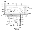
次に図2aを参照すると、図1aから図1dに示されるタイプのドアヒンジが、ドア枠に取り付ける枠本体部分101と、ドアに取り付けるドア部分301と、このドア部分301を枠本体部分101に枢動可能に接続するピボット連結部501とを備える。
Referring now to FIG. 2a, a door hinge of the type shown in FIGS. 1a to 1d includes a
枠本体部分101は、直方体すなわちブロック体の部材から成り、前側103、後側105、上部107、底部109、左端111、および右端113を備える。第1フランジ壁115は、枠本体部分101の枠正面すなわち主面117を形成するために、前側103から延伸している。本実施形態において、第1フランジ壁115は、左端111を超えて左方向に延伸し、枠正面117の延伸した左縁119を形成している。また本実施形態において、第2フランジ壁121は、右端113から延伸し、枠本体部分101の枠端面123を形成している。本実施形態において、第2フランジ壁121は、後側105を超えて後ろ方向に延伸し、枠端面123の延伸した後縁125を形成している。第1フランジ壁115および第2フランジ壁121は交差し、枠正面117と枠端面123との間に枠本体部分の角部127を形成している。
The frame
枠本体部分101の直方体形状は、強力かつ堅牢なアンカをヒンジに提供するために、ドア枠にほぞ継ぎにされるのに適している。本実施形態において、第1フランジ壁115および第2フランジ壁121には、ドア枠に枠本体部分101を取り付けるねじ等を受け入れる、穴(不図示)が含まれる。
The rectangular parallelepiped shape of the
本実施形態において、枠本体部分101は前側103から外側へ突出した支持部材129をさらに備え、この支持部材129は、上部107および底部109と同一平面上にある上面および下面を備える。支持部材129の上と下で、1対の開口スロット131が前側103から枠本体部分101に延伸している。
In the present embodiment, the frame
ドア部分301は、直方体すなわちブロック体の部材から成り、前側303、後側305、上部307、底部309、右端311、および左端313を備える。第1フランジ壁315は、ドア部分301のドア正面すなわち主面317を形成するために、前側303から延伸している。本実施形態において、第1フランジ壁315は、右端311を超えて右方向に延伸し、ドア正面317の延伸した右縁319を形成している。また本実施形態において、第2フランジ壁321は、左端313から延伸し、ドア部分301のドア端面323を形成している。本実施形態において、第2フランジ壁321は、後側305を超えて後ろ方向に延伸し、ドア端面323の延伸した後縁325を形成している。第1フランジ壁315および第2フランジ壁321は交差し、ドア正面317とドア端面323との間にドア部分の角部327を形成している。
The
ドア部分301の直方体形状は、強力かつ堅牢な支持をドアに提供するために、ほぞ継ぎにされるのに適している。本実施形態において、第1フランジ壁315および第2フランジ壁321には、ドアにドア部分301を取り付けるねじ等を受け入れるために、穴(不図示)が含まれる。
The rectangular shape of the
ドア部分301は、溝329を画定するために前側303および左端313で開き、この溝329は、ドア部分301に沿って右方向に右端311への経路の約90%延伸し、ドア部分301を横切って後ろ方向に後側305への経路の約75%延伸している。溝329は、ヒンジが閉位置のときに、ピボット連結部501および支持部材129を受け入れるように構成されている。
The
ピボット連結部501は第1アーム503を備え、本実施形態において、第1アーム503には凹所505が含まれる。また、本実施形態において、第1アーム503の一端が1対の突起507を備え、この突起507が、支持部材129によって略平行関係に離間されて配置され、貫通して延伸するピンによって支持部材129の遠位端に枢動可能に接続されることにより、第1枠本体部分の固定ピボット軸101aを提供する。つまり、第1アーム503と支持部材129との間のピボット接続は、枠本体部分101に対して空間に固定されている。本実施形態において、ピンは第1アーム503に対して固定され、支持部材129に対して回転可能である。
The
第1アーム503の他端を、貫通して延伸するピンによってドア部分301の上部307と底部309との間で枢動可能に接続することにより、第1ドア部分の変位可能ピボット軸301aを提供する。つまり、第1アーム503とドア部分301との間のピボット接続は、枠本体部分101に対して空間に移動可能である。さらに、ドア部分301は、第1アーム503に対して第1ドア部分の変位可能ピボット軸301aを中心として自由に回転する。本実施形態において、ピボット接続は、ドア部分301の左端313から右端311への経路の約30パーセント、および前側303から後側305への経路の約60%で配置されている。また本実施形態において、ピンは第1アーム503およびドア部分301に対して固定されている。
本実施形態において、ピボット連結部は第2アーム509をさらに備え、この第2アーム509は、支持部材129によって略平行関係に離間されて配置された、2つの略同様の部材を備える。第2アーム509の一端で、細長い部材が枠本体部分101のスロット131に延伸しており、この部材は貫通して延伸するピンによって支持部材129の近位端に枢動可能に接続されることにより、第2枠本体部分の固定ピボット軸101bを提供する。つまり、第2アーム509と枠本体部分101との間のピボット接続は、枠本体部分101に対して空間に固定されている。本実施形態において、ピンは枠本体部分101の上部107と底部109も貫通して延伸している。本実施形態において、ピボット接続は、枠本体部分101の左端111から右端113への経路の約70パーセント、および前側103から後側105への経路の約50%で配置されている。また本実施形態において、ピンは枠本体部分101および第2アーム509に対して固定されている。
In the present embodiment, the pivot connecting portion further includes a
第2アーム509の他端を、貫通して延伸するピンによってドア部分301の上部307と底部309との間で枢動可能に接続することにより、第2ドア部分の変位可能ピボット軸301bを提供する。つまり、第2アーム509とドア部分301との間のピボット接続は、枠本体部分101に対して空間に移動可能である。本実施形態において、ピボット接続は、ドア部分301の、左端313から右端311への経路の約5パーセント、および前側303から後側305への経路の約10%で、すなわちドア部分の角部327付近に配置されている。また本実施形態において、ピンは第2アーム509およびドア部分301に対して固定されている。
本実施形態において、枠本体部分101、ドア部分301、およびピボット連結部501は、ステンレス鋼から形成されている。また本実施形態において、枠本体部分101およびドア部分301は、単体構造である。
In the present embodiment, the frame
図2aに示される閉じた構成において、ドア正面317が枠正面117に対向しかつ平行である。第1ドア部分の変位可能ピボット軸301aは第1位置にあり、本実施形態において、この第1位置は、枠正面117の突出長さの範囲内である。第2ドア部分の変位可能ピボット軸301bは第1位置にあり、本実施形態において、この第1位置は、枠正面117の突出長さを超えている。ピボット連結部501および支持部材129の突出部は、溝129に受け入れられる。
In the closed configuration shown in FIG. 2a, the
次に、ヒンジの動作に関する態様を検討し、図2bを参照すると、例えばドアハンドルを引く動作によってドアを開くために適用される力Fが、第1アーム503とドア部分301との間のピボット接続に伝達され、これにより、第1枠本体部分の固定ピボット軸101aを中心とした第1アーム503の回転を開始する。引張力Fが加えられ続けるにつれて、第1ドア部分の変位可能ピボット軸301aは、枠正面117に沿って離れていく移動経路を表し、これにより、ドア部分301を枠本体部分101から遠ざける外側にスローし、開いた構成になる。
Next, consider aspects relating to the operation of the hinge, and referring to FIG. 2b, the force F applied to open the door, for example, by pulling the door handle, is the pivot between the
同時に、本実施形態においては、加えられた引張力Fが第2アーム509とドア部分301との間のピボット接続にも伝達され、これにより、第2枠本体部分の固定ピボット軸101bを中心とした第2アーム509の回転を引き起こす。引張力Fが続くにつれて、第2ドア部分の変位可能ピボット軸301bは、枠正面117に沿って離れていく移動経路を表し、これにより、ドア部分301は完全に開いた構成に導かれる。第2アーム509は、枠正面117と反対にドア部分の端面323を導くことにより改良されたドア部分301の経路の制御を提供することが有利であり、これにより、ドア正面317が枠端面123と適切に合致して、完全に開いた構成をもたらす。
At the same time, in the present embodiment, the applied tensile force F is also transmitted to the pivot connection between the
次に図2cを参照すると、ヒンジが完全に開いた構成である場合、第1ドア部分の変位可能ピボット軸301aは第2位置にあり、この第2位置は枠正面117に沿って離れている。本実施形態において、第2位置は枠正面117の突出長さの範囲内である。さらに、第2ドア部分の変位可能ピボット軸301bは第2位置にあり、この第2位置は枠正面117に沿って離れている。本実施形態において、第2位置は枠正面117の突出長さの範囲内である。本実施形態において、第2ドア部分の変位可能ピボット軸301bは、第1ドア部分の変位可能ピボット軸301aよりも枠正面117に沿ってさらに移動される。
Referring now to FIG. 2c, when the hinge is in a fully open configuration, the
完全に開いた構成において、ドア正面317は枠正面117に直行している。本実施形態において、ドア正面317は枠端面123とも合致する。さらに、ドア部分の端面323は枠正面117に対向している。また、第2アーム509の一部が、第1アーム503の凹所505によって受け入れられる。
In the fully open configuration, the
一実施形態において、ヒンジは、図3に示されるような、h11=53mm,h12=33mm,l1=47mm,d1=35mm,t1=3mm,h21=53mm,h22=33mm,l2=80mm,d2=26mm,t2=3mmである、おおよその寸法を有する。例として、本実施形態は、高さ約4mおよび厚さ約54mmであるドアを支持するのに適しているだろう。 In one embodiment, the hinge is as shown in FIG. 3, h11 = 53 mm, h12 = 33 mm, l1 = 47 mm, d1 = 35 mm, t1 = 3 mm, h21 = 53 mm, h22 = 33 mm, l2 = 80 mm, d2 = It has approximate dimensions of 26 mm, t2 = 3 mm. By way of example, this embodiment may be suitable for supporting a door that is about 4 m high and about 54 mm thick.
このように、本発明のヒンジは、大型のドアまたは重いドア用の強力かつ堅牢な支持を提供する。さらに、前述の従来技術のヒンジとは異なり、ヒンジが閉じた構成である場合、枠正面117およびドア正面317は直行関係ではなく平行に配置されているため、ヒンジがキャビネットの内側空間に入り込まないことが有利である。
Thus, the hinge of the present invention provides a strong and robust support for large or heavy doors. Further, unlike the above-described prior art hinge, when the hinge is in a closed configuration, the frame
本発明の一実施形態においては、第2アーム509が省かれる。
In one embodiment of the present invention, the
本発明の一実施形態においては、ピボット連結部501に、例えばナイロンブッシュである、摩擦低減部材が含まれる。
In one embodiment of the present invention, the
本発明の一実施形態においては、枠本体部分101、ドア部分301、およびピボット連結部501の一部または全部が、ステンレス鋼、アルミニウム、真鍮、またはプラスチックから形成されている。
In one embodiment of the present invention, part or all of the frame
本発明は、本発明の好ましい実施形態に関連して説明されており、添付の特許請求の範囲によって定義される本発明の範囲から逸脱することなく、多くの異なる方法で変更され得ることが理解されよう。 It will be understood that the present invention has been described in connection with preferred embodiments of the invention and can be varied in many different ways without departing from the scope of the invention as defined by the appended claims. Let's be done.
Claims (16)
横方向の範囲を有する第1枠面及び該第1枠面に対して概ね直交する第2枠面を含み、ドア枠に取り付けるほぞ継ぎ本体部分と、
ドア正面を含み、ドアに取り付けるほぞ継ぎドア部分と、
前記ドア部分を前記本体部分に枢動可能に接続するピボット連結部と
を備え、
前記ピボット連結部は、第1アームと、第2アームとを備え、
前記第1アームは、第1固定ピボット軸を中心として前記本体部分に連結され、かつ、第1変位可能ピボット軸を中心として前記ドア部分に連結され、
前記第1固定ピボット軸は、前記第1枠面の外側に配置され、
前記第1変位可能ピボット軸は、前記ヒンジが前記閉じた構成である場合の第1位置から、前記ヒンジが前記完全に開いた構成である場合の第2位置に変位し、該第2位置は、前記第1変位可能ピボット軸が、前記第1位置から、前記第1枠面の横方向に沿って、かつ、前記第1枠面から離れる方向に変位した位置であり、
前記第2アームは、第2固定ピボット軸を中心として前記本体部分に連結され、かつ、第2変位可能ピボット軸を中心として前記ドア部分に連結され、
前記第2固定ピボット軸は、前記本体部分の内側に配置され、
前記第2変位可能ピボット軸は、前記ヒンジが前記閉じた構成である場合の第1位置から、前記ヒンジが前記完全に開いた構成である場合の第2位置に変位し、該第2位置は、前記第2変位可能ピボット軸が、前記第1位置から、前記第1枠面の横方向に沿って、かつ、前記第1枠面から離れる方向に変位した位置であり、
前記ドア正面が、前記ヒンジが前記閉じた構成である場合に前記第1枠面に対して概ね平行であり、前記ヒンジが前記完全に開いた構成である場合に前記第1枠面に対して概ね直交する、ドアヒンジ。 A door hinge for supporting the door relative to the door frame and operable between a closed configuration and a fully open configuration;
A first frame surface having a lateral range and a second frame surface substantially orthogonal to the first frame surface, and a tenon joint main body portion attached to the door frame;
A mortise door part to be attached to the door including the front of the door;
A pivot coupling for pivotally connecting the door portion to the body portion;
The pivot connecting portion includes a first arm and a second arm,
The first arm is coupled to the body portion about a first fixed pivot axis, and is coupled to the door portion about a first displaceable pivot axis;
The first fixed pivot shaft is disposed outside the first frame surface;
The first displaceable pivot shaft is displaced from a first position when the hinge is in the closed configuration to a second position when the hinge is in the fully open configuration, the second position being The first displaceable pivot shaft is displaced from the first position along the lateral direction of the first frame surface and away from the first frame surface;
The second arm is connected to the body portion about a second fixed pivot axis and is connected to the door portion about a second displaceable pivot axis;
The second fixed pivot shaft is disposed inside the body portion;
The second displaceable pivot shaft is displaced from a first position when the hinge is in the closed configuration to a second position when the hinge is in the fully open configuration, and the second position is The second displaceable pivot shaft is a position displaced from the first position along the lateral direction of the first frame surface and away from the first frame surface;
The front of the door is generally parallel to the first frame surface when the hinge is in the closed configuration, and to the first frame surface when the hinge is in the fully open configuration. A door hinge that is generally orthogonal.
前記ドア端面は、前記ヒンジが前記完全に開いた構成である場合に、前記第1枠面と対向する、
請求項1から請求項10のいずれかに記載のドアヒンジ。 The door portion includes a door end surface generally orthogonal to the door front;
The door end surface is opposed to the first frame surface when the hinge is in the fully open configuration;
The door hinge in any one of Claims 1-10.
Applications Claiming Priority (3)
| Application Number | Priority Date | Filing Date | Title |
|---|---|---|---|
| GB1213089.4 | 2012-07-24 | ||
| GB1213089.4A GB2504281B (en) | 2012-07-24 | 2012-07-24 | Door hinge |
| PCT/GB2013/000323 WO2014016545A1 (en) | 2012-07-24 | 2013-07-24 | Door hinge |
Publications (3)
| Publication Number | Publication Date |
|---|---|
| JP2015526617A JP2015526617A (en) | 2015-09-10 |
| JP2015526617A5 JP2015526617A5 (en) | 2016-09-23 |
| JP6224708B2 true JP6224708B2 (en) | 2017-11-01 |
Family
ID=46881835
Family Applications (1)
| Application Number | Title | Priority Date | Filing Date |
|---|---|---|---|
| JP2015523603A Active JP6224708B2 (en) | 2012-07-24 | 2013-07-24 | Door hinge |
Country Status (15)
| Country | Link |
|---|---|
| US (1) | US9790718B2 (en) |
| EP (1) | EP2877661A1 (en) |
| JP (1) | JP6224708B2 (en) |
| CN (1) | CN104583517B (en) |
| AU (1) | AU2013294788B2 (en) |
| CA (1) | CA2879883C (en) |
| GB (1) | GB2504281B (en) |
| IL (1) | IL236903B (en) |
| IN (1) | IN2015DN01121A (en) |
| MX (1) | MX2015001097A (en) |
| NZ (1) | NZ704774A (en) |
| RU (1) | RU2615113C2 (en) |
| SG (1) | SG11201500610TA (en) |
| WO (1) | WO2014016545A1 (en) |
| ZA (1) | ZA201501205B (en) |
Families Citing this family (14)
| Publication number | Priority date | Publication date | Assignee | Title |
|---|---|---|---|---|
| EP3172903A1 (en) * | 2014-07-22 | 2017-05-31 | Tyco Electronics Raychem BVBA | Door hinge mechanism for telecommunicatons panel |
| CN106715813B (en) | 2014-09-11 | 2018-12-11 | Adc电信股份有限公司 | Door hinge mechanism for telecommunication panel |
| CN107178265A (en) * | 2016-03-09 | 2017-09-19 | 北京正文机械科技有限公司 | A kind of hinge arrangement |
| US11674345B2 (en) | 2016-04-19 | 2023-06-13 | Commscope, Inc. Of North Carolina | Door assembly for a telecommunications chassis with a combination hinge structure |
| US10539757B2 (en) | 2016-04-19 | 2020-01-21 | Commscope, Inc. Of North Carolina | Telecommunications chassis with slidable trays |
| WO2017189016A1 (en) * | 2016-04-29 | 2017-11-02 | Hewlett-Packard Development Company, L.P. | Printer door hinge assembly |
| CN105840029B (en) * | 2016-05-27 | 2017-05-24 | 刘文勋 | Double-arm small hinge |
| US9820586B1 (en) * | 2016-07-22 | 2017-11-21 | Goppion S.P.A. | Museum showcase with an articulated quadrilateral hinge, having a hook for holding it in a closed position |
| US9739079B1 (en) * | 2016-10-28 | 2017-08-22 | Helmut Guenschel | Hidden hinge for a display case |
| JP6896340B2 (en) * | 2017-07-27 | 2021-06-30 | アール・ビー・コントロールズ株式会社 | Mirror stand device |
| GB201712700D0 (en) * | 2017-08-08 | 2017-09-20 | Joseph Giles Ltd | Door hinge |
| CN107724834A (en) * | 2017-11-15 | 2018-02-23 | 浪潮金融信息技术有限公司 | Hinge means |
| CN109936649B (en) * | 2019-02-22 | 2020-09-08 | 维沃移动通信有限公司 | Connecting assembly and mobile terminal |
| AT522463B1 (en) * | 2019-06-27 | 2020-11-15 | Blum Gmbh Julius | Furniture drive |
Family Cites Families (34)
| Publication number | Priority date | Publication date | Assignee | Title |
|---|---|---|---|---|
| US2164757A (en) * | 1939-07-04 | Concealed hinge | ||
| FR447734A (en) | 1911-09-05 | 1913-01-13 | Robert Wahl | Improvements in making a sour or sour liquid |
| US1078786A (en) * | 1913-03-29 | 1913-11-18 | Frank Hanba | Automobile door-hinge. |
| US1484093A (en) * | 1921-11-21 | 1924-02-19 | Soss Joseph | Hinge |
| US1688996A (en) * | 1926-03-01 | 1928-10-23 | Soss Joseph | Concealed hinge |
| US1925209A (en) * | 1932-06-18 | 1933-09-05 | Joseph Soss | Concealed hinge |
| US2121790A (en) * | 1937-02-12 | 1938-06-28 | Etzel Paul | Hinge mounting for doors and the like |
| US2206708A (en) * | 1938-08-13 | 1940-07-02 | Walter W Stumpf | Hinge |
| US3001224A (en) * | 1960-05-16 | 1961-09-26 | Charles J Soss | Concealed hinge |
| FR1336667A (en) * | 1961-01-12 | 1963-09-06 | Ohg Bassan & C S R L | Hinge |
| US3611474A (en) * | 1968-10-31 | 1971-10-12 | Stanley Works | Invisible hinge |
| DE2034614A1 (en) * | 1969-07-22 | 1971-02-11 | Cencioni, Livio, Apnlia, Latina (Italien) | Hinge to be attached to an inner surface |
| DE2117828C3 (en) * | 1970-11-09 | 1982-09-16 | Arturo Salice S.p.A., Cantu, Como | Hinge joint for doors, flaps or the like. |
| DE2155950C3 (en) * | 1971-11-11 | 1978-05-11 | Fa. Richard Heinze, 4900 Herford | Door or flap hinge |
| IT955800B (en) * | 1972-05-24 | 1973-09-29 | Salice A Spa | ARTICULATED HINGE NOT IN SIGHT FOR FURNITURE WITH SNAP CLOSURE |
| FR2205089A5 (en) * | 1972-09-22 | 1974-05-24 | Drieu Rene | |
| AT348375B (en) * | 1972-12-07 | 1979-02-12 | Blum Gmbh Julius | ADJUSTABLE HINGE WITH AN OPENING ANGLE OF 90 DEGREES, WITH A BASE BODY THAT CAN BE FASTENED ON A COMPONENT, FOR EXAMPLE, A BASE BODY, AND A HOUSING, PREFERABLY INSERTED IN A FLAP |
| JPS5236946Y2 (en) * | 1972-12-29 | 1977-08-23 | ||
| US3881221A (en) * | 1974-01-14 | 1975-05-06 | Sos Consolidated | Invisible hinge |
| DE2912627C2 (en) * | 1979-03-30 | 1985-08-01 | Arturo Salice S.P.A., Novedrate, Como | Concealed hinge for doors, flaps or the like |
| DE3108224C2 (en) * | 1981-03-05 | 1985-07-11 | Karl Lautenschläger KG, Möbelbeschlagfabrik, 6107 Reinheim | Furniture hinge |
| JPS6053975U (en) * | 1983-09-21 | 1985-04-16 | スガツネ工業株式会社 | hinge attachment device |
| DE3515907A1 (en) * | 1985-05-03 | 1986-11-06 | Häfele KG, 7270 Nagold | HINGE, IN PARTICULAR FURNITURE HINGE |
| JPH0682345U (en) * | 1991-10-24 | 1994-11-25 | 株式会社ミサト製作所 | Furniture hinges |
| DE4418238A1 (en) * | 1994-05-25 | 1995-11-30 | Bosch Siemens Hausgeraete | Multi=link hinge for refrigerator door |
| IT248724Y1 (en) * | 1999-06-25 | 2003-02-12 | Koblenz Spa | CONCEALED HINGE, IN PARTICULAR FOR DOORS AND / OR FOR FURNITURE DOORS. |
| US6748626B2 (en) * | 2002-08-14 | 2004-06-15 | Scott D. Maurer | Articulated swing away hinge |
| DE20303262U1 (en) * | 2002-12-06 | 2004-04-15 | Niemann, Hans Dieter | Concealed hinge used as a connecting element between a door/window frame and a door/window leaf comprises connecting rods and rotating joints arranged in the closed operating state above or adjacent to each other |
| ITRM20030599A1 (en) | 2003-12-23 | 2005-06-24 | Salice Arturo Spa | HINGE WITH SPRING FOR FURNITURE. |
| CN201318087Y (en) * | 2008-12-22 | 2009-09-30 | 重庆美心(集团)有限公司 | Blind hinge structure with adjustable angle of 180 DEG |
| JP5563228B2 (en) * | 2009-02-24 | 2014-07-30 | パナソニック株式会社 | Door connecting member and door connecting structure using the same |
| US8307502B2 (en) * | 2009-10-20 | 2012-11-13 | Sub-Zero, Inc. | Integrated hinge assembly |
| DE102011000150B3 (en) * | 2011-01-14 | 2011-10-06 | Simonswerk, Gesellschaft mit beschränkter Haftung | Door hinge for convertible arrangement between door frame and door wing of door, has door wing-receiving body which is inserted in recess in narrow side of door wing |
| EP2570575B1 (en) * | 2011-09-16 | 2016-09-07 | Koblenz S.P.A. | A fully concealed hinge with integrated closing device for doors and/or openable furniture parts |
-
2012
- 2012-07-24 GB GB1213089.4A patent/GB2504281B/en active Active
-
2013
- 2013-07-24 WO PCT/GB2013/000323 patent/WO2014016545A1/en active Application Filing
- 2013-07-24 AU AU2013294788A patent/AU2013294788B2/en active Active
- 2013-07-24 RU RU2015106113A patent/RU2615113C2/en active
- 2013-07-24 SG SG11201500610TA patent/SG11201500610TA/en unknown
- 2013-07-24 US US14/417,195 patent/US9790718B2/en active Active
- 2013-07-24 CA CA2879883A patent/CA2879883C/en active Active
- 2013-07-24 MX MX2015001097A patent/MX2015001097A/en unknown
- 2013-07-24 CN CN201380042946.8A patent/CN104583517B/en active Active
- 2013-07-24 EP EP13759552.6A patent/EP2877661A1/en active Pending
- 2013-07-24 JP JP2015523603A patent/JP6224708B2/en active Active
- 2013-07-24 NZ NZ704774A patent/NZ704774A/en unknown
-
2015
- 2015-01-25 IL IL236903A patent/IL236903B/en active IP Right Grant
- 2015-02-11 IN IN1121DEN2015 patent/IN2015DN01121A/en unknown
- 2015-02-23 ZA ZA2015/01205A patent/ZA201501205B/en unknown
Also Published As
| Publication number | Publication date |
|---|---|
| AU2013294788A1 (en) | 2015-03-05 |
| IL236903B (en) | 2018-02-28 |
| GB201213089D0 (en) | 2012-09-05 |
| RU2615113C2 (en) | 2017-04-03 |
| CA2879883C (en) | 2018-11-27 |
| CN104583517A (en) | 2015-04-29 |
| GB2504281A (en) | 2014-01-29 |
| SG11201500610TA (en) | 2015-04-29 |
| CN104583517B (en) | 2018-05-18 |
| GB2504281B (en) | 2014-10-15 |
| CA2879883A1 (en) | 2014-01-30 |
| IN2015DN01121A (en) | 2015-06-26 |
| RU2015106113A (en) | 2016-09-10 |
| US20150167366A1 (en) | 2015-06-18 |
| EP2877661A1 (en) | 2015-06-03 |
| US9790718B2 (en) | 2017-10-17 |
| NZ704774A (en) | 2017-04-28 |
| AU2013294788B2 (en) | 2018-03-15 |
| JP2015526617A (en) | 2015-09-10 |
| ZA201501205B (en) | 2018-11-28 |
| MX2015001097A (en) | 2015-06-05 |
| WO2014016545A1 (en) | 2014-01-30 |
Similar Documents
| Publication | Publication Date | Title |
|---|---|---|
| JP6224708B2 (en) | Door hinge | |
| US5409308A (en) | Overhead cabinet with rotating door | |
| US8561259B2 (en) | Dampening hinge | |
| RU2416062C2 (en) | Door for domestic appliance | |
| KR101490160B1 (en) | Automatic closing door hinge | |
| CN113994061B (en) | Furniture driving device, suite and furniture | |
| KR102542345B1 (en) | Furniture hinges, furniture panels and furniture bodies | |
| JP2004346732A (en) | Framework structural member equipped with door | |
| US2955315A (en) | Refrigerator door stop | |
| CN204782443U (en) | Frame formula damping blind hinge | |
| US2812539A (en) | Hinge | |
| CA2045302C (en) | Hinge | |
| CN110761672A (en) | Storage cabinet | |
| US5201096A (en) | Hinge | |
| EP4227480A1 (en) | Cabinet, door system and hinge therefor | |
| JP3213896U (en) | Altar | |
| KR20220088194A (en) | Anti door closing apparatus | |
| KR20160136010A (en) | an account book mirror | |
| JP2519145B2 (en) | Slide hinge | |
| US20040123424A1 (en) | Pivotal shaft assembly | |
| JP2004229977A (en) | Storage cabinet | |
| IT202100019511A1 (en) | HINGE DEVICE FOR FURNITURE | |
| JPS5918057Y2 (en) | Door opening/closing storage device | |
| JP2018037619A (en) | cabinet | |
| KR20180014463A (en) | Hinged door hinge-coupled device |
Legal Events
| Date | Code | Title | Description |
|---|---|---|---|
| A621 | Written request for application examination |
Free format text: JAPANESE INTERMEDIATE CODE: A621 Effective date: 20160725 |
|
| A521 | Request for written amendment filed |
Free format text: JAPANESE INTERMEDIATE CODE: A523 Effective date: 20160804 |
|
| A871 | Explanation of circumstances concerning accelerated examination |
Free format text: JAPANESE INTERMEDIATE CODE: A871 Effective date: 20161031 |
|
| A711 | Notification of change in applicant |
Free format text: JAPANESE INTERMEDIATE CODE: A711 Effective date: 20161110 |
|
| A521 | Request for written amendment filed |
Free format text: JAPANESE INTERMEDIATE CODE: A821 Effective date: 20161110 |
|
| A975 | Report on accelerated examination |
Free format text: JAPANESE INTERMEDIATE CODE: A971005 Effective date: 20161124 |
|
| A131 | Notification of reasons for refusal |
Free format text: JAPANESE INTERMEDIATE CODE: A131 Effective date: 20161220 |
|
| A601 | Written request for extension of time |
Free format text: JAPANESE INTERMEDIATE CODE: A601 Effective date: 20170315 |
|
| A601 | Written request for extension of time |
Free format text: JAPANESE INTERMEDIATE CODE: A601 Effective date: 20170519 |
|
| A521 | Request for written amendment filed |
Free format text: JAPANESE INTERMEDIATE CODE: A523 Effective date: 20170620 |
|
| TRDD | Decision of grant or rejection written | ||
| A01 | Written decision to grant a patent or to grant a registration (utility model) |
Free format text: JAPANESE INTERMEDIATE CODE: A01 Effective date: 20170808 |
|
| A601 | Written request for extension of time |
Free format text: JAPANESE INTERMEDIATE CODE: A601 Effective date: 20170901 |
|
| A61 | First payment of annual fees (during grant procedure) |
Free format text: JAPANESE INTERMEDIATE CODE: A61 Effective date: 20171005 |
|
| R150 | Certificate of patent or registration of utility model |
Ref document number: 6224708 Country of ref document: JP Free format text: JAPANESE INTERMEDIATE CODE: R150 |
|
| R250 | Receipt of annual fees |
Free format text: JAPANESE INTERMEDIATE CODE: R250 |
|
| R250 | Receipt of annual fees |
Free format text: JAPANESE INTERMEDIATE CODE: R250 |
|
| R250 | Receipt of annual fees |
Free format text: JAPANESE INTERMEDIATE CODE: R250 |
|
| R250 | Receipt of annual fees |
Free format text: JAPANESE INTERMEDIATE CODE: R250 |