JP6223152B2 - Image forming system, image processing apparatus, and image processing apparatus control method - Google Patents
Image forming system, image processing apparatus, and image processing apparatus control methodInfo
- Publication number
- JP6223152B2 JP6223152B2 JP2013246933A JP2013246933A JP6223152B2 JP 6223152 B2 JP6223152 B2 JP 6223152B2 JP 2013246933 A JP2013246933 A JP 2013246933A JP 2013246933 A JP2013246933 A JP 2013246933A JP 6223152 B2 JP6223152 B2 JP 6223152B2
- Authority
- JP
- Japan
- Prior art keywords
- image forming
- forming apparatus
- image processing
- information
- power state
- Prior art date
- Legal status (The legal status is an assumption and is not a legal conclusion. Google has not performed a legal analysis and makes no representation as to the accuracy of the status listed.)
- Active
Links
Images


Classifications
-
- H—ELECTRICITY
- H04—ELECTRIC COMMUNICATION TECHNIQUE
- H04N—PICTORIAL COMMUNICATION, e.g. TELEVISION
- H04N1/00—Scanning, transmission or reproduction of documents or the like, e.g. facsimile transmission; Details thereof
- H04N1/00127—Connection or combination of a still picture apparatus with another apparatus, e.g. for storage, processing or transmission of still picture signals or of information associated with a still picture
- H04N1/00204—Connection or combination of a still picture apparatus with another apparatus, e.g. for storage, processing or transmission of still picture signals or of information associated with a still picture with a digital computer or a digital computer system, e.g. an internet server
- H04N1/00244—Connection or combination of a still picture apparatus with another apparatus, e.g. for storage, processing or transmission of still picture signals or of information associated with a still picture with a digital computer or a digital computer system, e.g. an internet server with a server, e.g. an internet server
-
- G—PHYSICS
- G06—COMPUTING; CALCULATING OR COUNTING
- G06F—ELECTRIC DIGITAL DATA PROCESSING
- G06F3/00—Input arrangements for transferring data to be processed into a form capable of being handled by the computer; Output arrangements for transferring data from processing unit to output unit, e.g. interface arrangements
- G06F3/12—Digital output to print unit, e.g. line printer, chain printer
- G06F3/1201—Dedicated interfaces to print systems
- G06F3/1202—Dedicated interfaces to print systems specifically adapted to achieve a particular effect
- G06F3/1218—Reducing or saving of used resources, e.g. avoiding waste of consumables or improving usage of hardware resources
- G06F3/1221—Reducing or saving of used resources, e.g. avoiding waste of consumables or improving usage of hardware resources with regard to power consumption
-
- G—PHYSICS
- G06—COMPUTING; CALCULATING OR COUNTING
- G06F—ELECTRIC DIGITAL DATA PROCESSING
- G06F3/00—Input arrangements for transferring data to be processed into a form capable of being handled by the computer; Output arrangements for transferring data from processing unit to output unit, e.g. interface arrangements
- G06F3/12—Digital output to print unit, e.g. line printer, chain printer
- G06F3/1201—Dedicated interfaces to print systems
- G06F3/1223—Dedicated interfaces to print systems specifically adapted to use a particular technique
- G06F3/1229—Printer resources management or printer maintenance, e.g. device status, power levels
- G06F3/1231—Device related settings, e.g. IP address, Name, Identification
-
- G—PHYSICS
- G06—COMPUTING; CALCULATING OR COUNTING
- G06F—ELECTRIC DIGITAL DATA PROCESSING
- G06F3/00—Input arrangements for transferring data to be processed into a form capable of being handled by the computer; Output arrangements for transferring data from processing unit to output unit, e.g. interface arrangements
- G06F3/12—Digital output to print unit, e.g. line printer, chain printer
- G06F3/1201—Dedicated interfaces to print systems
- G06F3/1223—Dedicated interfaces to print systems specifically adapted to use a particular technique
- G06F3/1229—Printer resources management or printer maintenance, e.g. device status, power levels
- G06F3/1232—Transmitting printer device capabilities, e.g. upon request or periodically
-
- G—PHYSICS
- G06—COMPUTING; CALCULATING OR COUNTING
- G06F—ELECTRIC DIGITAL DATA PROCESSING
- G06F3/00—Input arrangements for transferring data to be processed into a form capable of being handled by the computer; Output arrangements for transferring data from processing unit to output unit, e.g. interface arrangements
- G06F3/12—Digital output to print unit, e.g. line printer, chain printer
- G06F3/1201—Dedicated interfaces to print systems
- G06F3/1278—Dedicated interfaces to print systems specifically adapted to adopt a particular infrastructure
- G06F3/1285—Remote printer device, e.g. being remote from client or server
-
- H—ELECTRICITY
- H04—ELECTRIC COMMUNICATION TECHNIQUE
- H04N—PICTORIAL COMMUNICATION, e.g. TELEVISION
- H04N1/00—Scanning, transmission or reproduction of documents or the like, e.g. facsimile transmission; Details thereof
- H04N1/00885—Power supply means, e.g. arrangements for the control of power supply to the apparatus or components thereof
- H04N1/00888—Control thereof
- H04N1/00896—Control thereof using a low-power mode, e.g. standby
-
- H—ELECTRICITY
- H04—ELECTRIC COMMUNICATION TECHNIQUE
- H04N—PICTORIAL COMMUNICATION, e.g. TELEVISION
- H04N2201/00—Indexing scheme relating to scanning, transmission or reproduction of documents or the like, and to details thereof
- H04N2201/0077—Types of the still picture apparatus
- H04N2201/0094—Multifunctional device, i.e. a device capable of all of reading, reproducing, copying, facsimile transception, file transception
-
- Y—GENERAL TAGGING OF NEW TECHNOLOGICAL DEVELOPMENTS; GENERAL TAGGING OF CROSS-SECTIONAL TECHNOLOGIES SPANNING OVER SEVERAL SECTIONS OF THE IPC; TECHNICAL SUBJECTS COVERED BY FORMER USPC CROSS-REFERENCE ART COLLECTIONS [XRACs] AND DIGESTS
- Y02—TECHNOLOGIES OR APPLICATIONS FOR MITIGATION OR ADAPTATION AGAINST CLIMATE CHANGE
- Y02D—CLIMATE CHANGE MITIGATION TECHNOLOGIES IN INFORMATION AND COMMUNICATION TECHNOLOGIES [ICT], I.E. INFORMATION AND COMMUNICATION TECHNOLOGIES AIMING AT THE REDUCTION OF THEIR OWN ENERGY USE
- Y02D10/00—Energy efficient computing, e.g. low power processors, power management or thermal management
Description
本発明は、画像形成装置と画像処理コントローラとが連携して動作する画像形成システムに関する。 The present invention relates to an image forming system in which an image forming apparatus and an image processing controller operate in cooperation.
近年、画像形成装置や画像処理コントローラの機器に対する省電力化の要望に伴い、画像形成装置が一定時間操作されない等の条件で画像形成装置の電力状態を省電力状態に移行する技術が提案されている(特許文献1〜2参照)。 2. Description of the Related Art In recent years, a technology for shifting the power state of an image forming apparatus to a power saving state on the condition that the image forming apparatus is not operated for a certain period of time has been proposed in response to a demand for power saving for devices such as image forming apparatuses and image processing controllers. (See Patent Documents 1 and 2).
このような画像形成装置では、プリンタ部によるプリント処理およびスキャナ部によるスキャナ処理が終了してから一定時間以上経過した場合や、外部機器との通信が終了してから一定時間以上経過した場合に、画像形成装置が省電力状態に移行する。 In such an image forming apparatus, when a certain time or more has elapsed since the printing process by the printer unit and the scanner process by the scanner unit have been completed, or when a certain time or more has elapsed since the communication with the external device has been completed, The image forming apparatus shifts to a power saving state.
ところで、このような画像形成装置には、画像形成装置と連携して画像処理を行う画像処理コントローラが接続されることがある。画像形成装置に接続される画像処理コントローラは、画像形成装置の情報(接続装備情報、給紙段情報、用紙情報、トナー情報など)を定期的に取得している。そして、画像処理コントローラは、取得した画像形成装置の情報を使って、画像処理コントローラ自身が保持する画像形成装置情報の更新をする。また、画像処理コントローラは、取得した画像形成装置の情報を使って、画像形成装置を利用するユーザのコンピュータに、取得した画像形成装置情報を通知する。 By the way, an image processing controller that performs image processing in cooperation with the image forming apparatus may be connected to such an image forming apparatus. The image processing controller connected to the image forming apparatus periodically acquires information on the image forming apparatus (connection equipment information, paper feed stage information, paper information, toner information, etc.). Then, the image processing controller updates the image forming apparatus information held by the image processing controller itself using the acquired information of the image forming apparatus. In addition, the image processing controller notifies the acquired image forming apparatus information to the computer of the user who uses the image forming apparatus using the acquired image forming apparatus information.
このように、画像形成装置と画像処理コントローラと間では、定期的に通信が行われているので、画像形成装置の情報が更新されると所定時間以内に画像処理コントローラに反映され、画像形成システム全体の情報の統一性が保たれている。 As described above, since communication is regularly performed between the image forming apparatus and the image processing controller, when the information of the image forming apparatus is updated, it is reflected in the image processing controller within a predetermined time, and the image forming system The uniformity of the entire information is maintained.
しかし、画像処理コントローラも、使用されていない状態等では、省電力状態に移行する。画像処理コントローラの省電力状態中には、画像形成装置と画像処理コントローラと間での定期的な通信も行われない。このため、画像処理コントローラの省電力状態中に画像形成装置の情報が変化した場合、省電力状態から復帰した直後は、画像形成システム全体の情報の統一性が崩れてしまう場合がある。 However, the image processing controller also shifts to a power saving state when not in use. During the power saving state of the image processing controller, periodic communication between the image forming apparatus and the image processing controller is not performed. For this reason, when the information of the image forming apparatus changes during the power saving state of the image processing controller, the uniformity of the information of the entire image forming system may be lost immediately after returning from the power saving state.
このような場合、画像形成装置を利用するユーザのコンピュータに、画像形成装置の変化前の情報が通知されてしまい、ユーザが変化前の情報に基づいてジョブを作成してしまう可能性があった。この場合、ジョブに基づく出力がユーザの意図と異なるものとなったり、画像形成装置が実行できないジョブが作成されてしまう等の誤動作が発生する可能性があった。 In such a case, information before the change of the image forming apparatus is notified to the computer of the user who uses the image forming apparatus, and the user may create a job based on the information before the change. . In this case, the output based on the job may be different from the user's intention, or a malfunction may occur such as creating a job that cannot be executed by the image forming apparatus.
本発明は、上記の問題点を解決するためになされたものである。本発明の目的は、画像処理コントローラの省電力中に画像形成装置の構成に変更が発生した場合でも、画像形成システム全体の情報の統一性を図り、該統一性が崩れることによって発生する誤動作を防止する仕組みを提供することである。 The present invention has been made to solve the above problems. The object of the present invention is to ensure the uniformity of the information of the entire image forming system even when a change occurs in the configuration of the image forming apparatus during the power saving of the image processing controller, and to prevent a malfunction caused by the loss of the uniformity. It is to provide a mechanism to prevent.
本発明は、ネットワークを介して外部装置から送信された印刷要求に基づいて画像データを生成し、生成した前記画像データを送信する画像処理装置と、前記画像処理装置から送信された前記画像データに基づいて印刷を行う画像形成装置と、を備える画像形成システムであって、前記画像処理装置は、前記画像形成装置から前記画像形成装置の情報を取得する取得手段と、前記取得手段によって取得された前記画像形成装置の情報を記憶する記憶手段と、前記外部装置からの要求に従って前記外部装置に前記記憶手段によって記憶された前記画像形成装置の情報を送信する送信手段と、所定の条件を満たしたことに基づいて前記画像処理装置の状態を第1電力状態から前記第1電力状態より省電力の第2電力状態に移行する移行手段と、所定の条件を満たしたことに基づいて前記画像処理装置の状態を前記第2電力状態から前記第1電力状態に復帰させる復帰手段と、を有し、前記復帰手段が前記画像処理装置の状態を前記第2電力状態から前記第1電力状態に復帰させたときに、前記取得手段は、前記画像形成装置から前記画像形成装置の最新の情報を取得し、前記記憶手段は、前記最新の情報で前記情報を更新する、ことを特徴とする。 The present invention is an image data generated based on a print request sent from an external device via a network, an image processing apparatus for transmitting the image data generated by the image data transmitted from the pre-Symbol image processing apparatus An image forming system comprising: an image forming apparatus that performs printing based on the image forming apparatus, wherein the image processing apparatus is acquired by the acquisition unit that acquires information on the image forming apparatus from the image forming apparatus; A storage unit that stores information on the image forming apparatus; a transmission unit that transmits information on the image forming apparatus stored in the storage unit to the external apparatus in accordance with a request from the external apparatus; and a predetermined condition is satisfied. And a transition means for shifting the state of the image processing apparatus from the first power state to the second power saving state from the first power state based on Recovery means for returning the state of the image processing apparatus from the second power state to the first power state based on satisfying the above condition, wherein the return means changes the state of the image processing apparatus to the first power state. When returning from the second power state to the first power state, the acquisition unit acquires the latest information of the image forming apparatus from the image forming apparatus, and the storage unit stores the latest information with the latest information. The information is updated.
本発明によれば、画像処理装置の省電力中に画像形成装置の構成に変更が発生した場合でも、画像形成システム全体の情報の統一性を図り、該統一性が崩れることによって発生する誤動作を防止することができる。 According to the present invention, even when a change occurs in the configuration of the image forming apparatus during power saving of the image processing apparatus, the information of the entire image forming system is unified, and a malfunction that occurs due to the loss of the uniformity. Can be prevented.
以下、本発明を実施するための形態について図面を用いて説明する。 Hereinafter, embodiments for carrying out the present invention will be described with reference to the drawings.
図1は、本発明の一実施例を示す画像形成システムの全体構成の一例を示す図である。
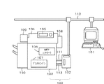
画像形成システム100は、画像処理コントローラ102と、画像形成装置103と、を備えている。そして、この画像形成システム100は、クライアントコンピュータ101と通信可能に接続されている。
FIG. 1 is a diagram showing an example of the overall configuration of an image forming system showing an embodiment of the present invention.
The
クライアントコンピュータ101と画像処理コントローラ102とは、イーサネット(登録商標)等のネットワーク113を介して通信可能に接続されている。また、画像処理コントローラ102と画像形成装置103とは、制御ケーブル111および画像ビデオケーブル112を介して接続されている。
The
なお、本実施例では、画像形成装置103は、ネットワーク113に直接接続されていない。つまり、画像形成装置103とクライアントコンピュータ101とは、画像処理コントローラ102を介して通信する。なお、画像形成装置103は、ネットワーク113に接続することも可能である。つまり、画像形成装置103は、直接、クライアントコンピュータ101と通信可能に接続することも可能である。
In this embodiment, the
クライアントコンピュータ101は、アプリケーションを起動させて画像形成装置103に印刷指示などを行う。画像処理コントローラ102は、画像形成装置103と連携して画像処理を行う。画像形成装置103は、MFP(Multiple Function Peripheral)である。
The
<画像形成装置および画像処理コントローラの構成>
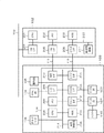
図2は、画像形成装置103および画像処理コントローラ102のハードウェア構成の一例を示すブロック図である。
画像処理コントローラ102は、CPU201、メモリ202、HDD203、ネットワークI/F204およびネットワークI/F205、並びにビデオI/F206、電源制御部217を有している。
<Configuration of Image Forming Apparatus and Image Processing Controller>
FIG. 2 is a block diagram illustrating an example of a hardware configuration of the
The
CPU201は、システムバス207を介して画像処理コントローラ102の各部の制御、演算、及び記憶装置(メモリ202やHDD203)に格納されたプログラムの実行を行う。メモリ202は、CPU201のワークメモリとして使用される。ハードディスク(HDD)203は、大容量の記憶装置であり、CPU201により実行される各種制御プログラムおよび画像データを格納している。なお、HDDの代わりにSSD(Solid State Drive)等の他の記憶装置を設けてもよい。
The
ネットワークI/F(NW I/F)204は、ネットワーク113を介してクライアントコンピュータ101などの他の装置と通信を行う。また、ネットワークI/F(NW I/F)205は、制御ケーブル111を介して画像形成装置103と制御コマンド等の送受信を行う。ビデオI/F206は、画像ビデオケーブル112を介して画像形成装置103と画像データの送受信を行う。電源制御部217は、画像処理コントローラ102各部の電力供給制御を行う。
A network I / F (NW I / F) 204 communicates with other devices such as the
また、画像形成装置103は、スキャナ部104、操作部105、MFPコントローラ106、プリンタ部107、ファックス部108、IDカードリーダ109、およびフィニッシャ110を有している。
The
スキャナ部104は、原稿を読み取って画像データを入力する。操作部105は、各種キーやパネルを有する。また、操作部105は、各種キーを介して、ユーザから各種指示を受け付ける。また、操作部105は、パネルを介して各種情報を表示する。
The
MFPコントローラ106は、上記したスキャナ部104やプリンタ部107などを制御する。このMFPコントローラ106の詳細は後述する。プリンタ部107は、画像データに基づいて用紙に印刷を行う。ファックス部108は、不図示の電話回線に接続され、当該電話回線等を介してファクシミリの入出力処理を行う。
The
IDカードリーダ109は、ユーザを識別するためのIDカードから情報を読み取る。フィニッシャ110は、プリンタ部107により画像が形成されたシート(以下、用紙)を受け取って、当該受け取った用紙に対して、排紙、ソート、ステイプル、パンチ、および裁断などの加工(後処理)を施す後処理装置である。なお、フィニッシャ110は、画像形成装置103本体と着脱可能である。
The
上記構成の画像形成装置103は、以下の機能を実行することができる。
〔コピー機能〕
スキャナ部104により読み取られた原稿の画像データをHDD211に記録すると共に、当該画像データに基づいてプリンタ部107が用紙に印刷を行う。〔SEND機能〕
スキャナ部104により読み取られた原稿の画像データを、ネットワークを介してクライアントコンピュータ101に送信する。〔BOX機能〕
スキャナ部104により読み取られた原稿の画像データをHDD211に記録する。また、クライアントコンピュータ101から送信された画像データをHDD211に記憶する。〔プリント機能〕
クライアントコンピュータ101から送信されたPDL(Page Description Language)データをプリンタ部107が解釈して印刷する。
The
[Copy function]
The document image data read by the
The original image data read by the
Document image data read by the
The
画像処理コントローラ102は、画像形成装置103の情報(例えば、フィニッシャ等の接続装備情報、給紙段情報、用紙情報、トナー情報など)を定期的に取得している。さらに、画像処理コントローラ102は、該取得した画像形成装置の情報を用いて、画像処理コントローラ102で保持する画像形成装置情報の更新をする。該画像形成装置の情報は、画像処理コントローラ102内のHDD203(図2)等に実装されるデータベースで記憶・管理されている。また、画像処理コントローラ102は、上記画像形成装置103の情報を、画像形成装置103を利用するユーザのコンピュータに通知する。なお、これらの制御は、メモリ202またはHDD203に記憶されたプログラムをCPU201が読み出して実行することにより実現される。
The
<画像形成装置のMFPコントローラの詳細>
ここで図2を参照して、画像形成装置103のMFPコントローラ106の詳細を説明する。
<Details of MFP Controller of Image Forming Apparatus>
Details of the
MFPコントローラ106は、CPU208、メモリ209、ネットワークI/F210、HDD211、エンジンI/F212、ビデオI/F213、リーダI/F215、ファックスI/F216および電源制御部218を有している。
The
CPU208は、記憶装置(メモリ209やHDD211)に格納されたプログラムを実行し、システムバス214を介して、画像形成装置103の各部の制御、演算を行う。メモリ209は、CPU208のワークメモリとして使用される。ネットワークI/F(NW I/F)210は、制御ケーブル111を介して画像処理コントローラ102と制御コマンドの送受信を行う。
The
ハードディスクドライブ(HDD)211は、大容量の記憶装置であり、CPU208により実行される各種制御プログラムや画像データを格納している。なお、HDDの代わりにSSD(Solid State Drive)等の他の記憶装置を設けてもよい。
A hard disk drive (HDD) 211 is a large-capacity storage device, and stores various control programs executed by the
エンジンI/F212は、プリンタ部107と制御コマンドの送受信を行う。ビデオI/F213は、画像ビデオケーブル112を介して画像処理コントローラ102と画像データの送受信を行う。リーダI/F215は、スキャナ部104および操作部105と制御コマンドの送受信を行う。ファックスI/F216は、ファックス部108を接続するためのインタフェースである。電源制御部218は、画像形成装置103の各部への電力供給を制御する。
The engine I /
以下、画像処理コントローラ102および画像形成装置の電源制御について説明する。
画像処理コントローラ102は、電源制御部217によって電源が管理されている。画像処理コントローラ102がスタンバイ状態のとき、電源制御部217は、CPU201、メモリ202、HDD203、ネットワークI/F204、ネットワークI/F205およびビデオI/F206の各部に電力が供給されるように電源を制御する。
Hereinafter, power control of the
The power supply of the
また、画像処理コントローラ102が省電力状態のとき、電源制御部217は、CPU201、HDD203、ビデオI/F206への電力供給を停止する。省電力状態のとき、電源制御部217は、メモリ202、ネットワークI/F204およびネットワークI/F205などの限られた部分だけに電力が供給されるように電源を制御する。
Further, when the
一方、画像形成装置103は、電源制御部218によって電源が管理されている。画像形成装置103がスタンバイ状態のとき、電源制御部218は、スキャナ部104、操作部105、MFPコントローラ106、プリンタ部107、ファックス部108、IDカードリーダ109およびフィニッシャ110に電力を供給するように制御する。
On the other hand, the power supply of the
また、画像形成装置103が省電力状態のとき、電源制御部218は、スキャナ部104や操作部105、プリンタ部107、IDカードリーダ109、フィニッシャ110への電力の供給を停止させる。また、省電力状態のとき、電源制御部218は、MFPコントローラ106のCPU208、HDD211、エンジンI/F212、ビデオI/F213、リーダI/F215、ファックスI/F216への電力の供給も停止させる。省電力状態では、電源制御部218、メモリ209およびネットワークI/F210などの限られた部分への電力供給を行い、その他の部分への電力供給を停止する。
When the
<画像処理コントローラのソフトウェア構成>
図3は、画像処理コントローラ102のソフトウェア構成の一例を示すブロック図である。図3を参照して、画像処理コントローラ102のソフトウェア構成について説明する。なお、図3に示す各ソフトウェアは、画像処理コントローラ102のメモリ202またはHDD203に記憶されたプログラムをCPU201が読み出して実行することにより実現される。
<Software configuration of image processing controller>
FIG. 3 is a block diagram illustrating an example of a software configuration of the
OS421は、画像処理コントローラ102の基本ソフトであるOS(オペレーティングシステム)を示している。プリントサーバアプリケーション401は、CPU201で実行されるOS421上で動作するアプリケーションソフトウェアである。プリントサーバアプリケーション401は、組み版編集部411、JOB制御部412、およびRIP処理部413を有し、画像処理を含む各種所定の処理を実行する。
An
組み版編集部411は、クライアントコンピュータ101からの指示に基づき、ページ毎の画像データを製本組み版フォーマットに編集する組み版編集処理を行う編集部である。JOB制御部412は、クライアントコンピュータ101からの指示に基づき、印刷JOBの制御を行う制御部である。具体的には、JOB制御部412は、クライアントコンピュータ101からの印刷データの受信やその指示とその印刷JOBの印刷順番制御を行う。RIP処理部413は、組み版編集部411による組み版時や、JOB制御部412において実際の画像形成処理を行う場合にPDLを印刷可能なラスターイメージに変換処理をする処理部である。
The
<画像処理コントローラの電力状態の遷移>
図4は、画像処理コントローラ102の電力状態の遷移の一例を示す状態遷移図である。
本実施例の画像処理コントローラ102は、電源OFF状態501、スタンバイ状態502、ジョブ実行状態503、省電力状態504のいずれかの電力状態になる。
<Transition of power state of image processing controller>
FIG. 4 is a state transition diagram illustrating an example of the transition of the power state of the
The
本実施例では、上記した4つの状態を例示したが、本発明はこれに限らず、画像処理コントローラ102は、他の電力状態になってもよい。例えば、画像処理コントローラ102は、サスペンド状態やハイバネーション状態になってもよい。
In the present embodiment, the four states described above are illustrated, but the present invention is not limited to this, and the
サスペンド状態とは、画像処理コントローラ102がスタンバイ状態502に高速で復帰可能な状態である。このサスペンド状態では、メモリ202への通電が維持されており、画像処理コントローラ102は、メモリ202に記憶した画像処理コントローラ102の状態を用いて画像処理コントローラ102がスタンバイ状態502に起動する。
The suspended state is a state in which the
また、ハイバネーション状態も、画像処理コントローラ102がスタンバイ状態に高速で復帰可能な状態である。このハイバネーション状態では、電力状態が電源OFF状態501と同様であって、画像処理コントローラ102の各部への電力供給は停止される。ただし、電源OFF状態501と異なるのは、ハイバネーション状態に移行する前に、画像処理コントローラ102の状態がHDD203に記憶されることである。ハイバネーション状態からスタンバイ状態に復帰する場合には、画像処理コントローラ102は、HDD203に記憶された情報に基づいて、高速復帰する。
The hibernation state is also a state in which the
画像処理コントローラ102の電力状態を消費電力の高い順に並べると、ジョブ実行状態503>スタンバイ状態502>省電力状態504>電源OFF状態501となる。
When the power states of the
電源OFF状態501は、画像処理コントローラ102の不図示の電源スイッチ(例えばシーソースイッチ)がOFFになっている状態であり、画像処理コントローラ102の全ての構成に対して電力供給が停止する。電源OFF状態501において、ユーザが画像処理コントローラ102の電源スイッチをONにすると、スタンバイ状態502に遷移する。
The power OFF
スタンバイ状態502は、画像処理コントローラ102がクライアントコンピュータ101からのアクセスを待機している状態であり、画像処理コントローラ102の全ての構成に対して電力供給が行われる。なおスタンバイ状態502では、画像処理コントローラ102の構成のうち、必ずしも全ての構成に対して電力供給が行われる必要はない。必須となる構成には電力供給され、それ以外の構成(例えばビデオI/F206等)には電力供給されないようにしてもよい。スタンバイ状態502において、クライアントコンピュータ101からネットワークアクセスを受け付けると、画像処理コントローラ102は、ジョブ実行状態503に遷移する。また、スタンバイ状態502において、スリープ移行要因があると、画像処理コントローラ102は、省電力状態504に遷移する。
The
スリープ移行要因としては、例えば、以下の(1)〜(3)などが該当する。
(1)ユーザがスリープ移行ボタン(図示せず)を押したこと。
(2)スタンバイ状態502で印刷ジョブなどを実行しない状態で所定時間が経過したこと。
(3)クライアントコンピュータ101から画像処理コントローラ102にネットワークアクセスをしない状態で所定時間が経過したこと。
As the sleep transition factor, for example, the following (1) to (3) are applicable.
(1) The user has pressed a sleep transition button (not shown).
(2) A predetermined time has passed without executing a print job or the like in the
(3) A predetermined time has elapsed without the network access from the
また、スタンバイ状態502において、ユーザが画像処理コントローラ102の電源スイッチをOFFにすると、シャットダウン処理が実行されて、画像処理コントローラ102は、電源OFF状態501に遷移する。シャットダウン処理とは、画像処理コントローラ102を終了させるために、OSやアプリケーションを終了させる処理のことである。
When the user turns off the power switch of the
ジョブ実行状態503は、画像処理コントローラ102がジョブを実行している状態であり、画像処理コントローラ102の全ての構成に対して電力供給が行われる。なお、ジョブ実行状態503でも、画像処理コントローラ102の構成のうち、必ずしも全ての構成に対して電力供給が行われる必要はない。必須となる構成には電力供給され、それ以外の構成(例えばビデオI/F206等)には電力供給されないようにしてもよい。また、ジョブの実行に使用されないユニットに対しては電力供給されないようにしてもよい。具体的には、印刷せずに印刷ジョブの編集だけをしている場合には、印刷ジョブの編集に使用されないビデオI/F206等などへの電力供給を停止してもよい。ジョブ実行状態503において、ジョブを終了すると、スタンバイ状態502に遷移する。
A
省電力状態504は、画像処理コントローラ102が省電力で待機している状態であり、画像処理コントローラ102の構成のうち、ネットワークI/F204を含む一部の構成に対して電力供給が行われる状態である。この省電力状態504では、ビデオI/F206に対しては電力供給が停止される。省電力状態504において、スリープ復帰要因を受け付けると、スタンバイ状態502に遷移する。なお、ネットワークI/F204およびネットワークI/F205が、ネットワークを介して送信される簡単なパケットに対して、省電力状態504のままで、応答することができる。この機能を代理応答と言う。簡単なパケットとして、ARP要求、SNMP状態取得、ICMP近隣探索などのパケットが挙げられる。なお、ARPは、Address Resolution Protocolを示す。また、SNMPは、Simple Network Management Protocolを示す。また、ICMPは、Internet Control Message Protocolを示す。
The
スリープ復帰要因としては、以下の(1)〜(3)などが該当する。
(1)ユーザがスリープ復帰ボタンを押したこと。
(2)クライアントコンピュータ101からネットワークアクセスを受け付けたこと。
(3)画像形成装置103からネットワークアクセスを受け付けたこと。
The following (1) to (3) correspond to the sleep recovery factors.
(1) The user has pressed the sleep return button.
(2) Accepting network access from the
(3) Accepting network access from the
以下、図5、図6を用いて、画像処理コントローラ102が省電力状態504に移行する場合と省電力状態504から復帰する場合について説明する。
Hereinafter, a case where the
<画像処理コントローラが省電力状態に移行するときの画像処理コントローラの動作説明>
まず、図5を参照して、実施例1において画像処理コントローラ102が省電力状態504に移行する場合の画像処理コントローラ102の動作を説明する。
<Description of the operation of the image processing controller when the image processing controller shifts to the power saving state>
First, the operation of the
図5は、実施例1において画像処理コントローラ102が省電力状態504に移行する場合の画像処理コントローラ102の動作の一例を示すフローチャートである。なお、図5に示すフローチャートの処理は、メモリ202に展開されたプログラムをCPU201が実行することにより実現される。
FIG. 5 is a flowchart illustrating an example of the operation of the
画像処理コントローラ102がジョブを実行した後など画像処理コントローラ102がスタンバイ状態502に移行すると、CPU201は、スリープ移行要因の発生を監視し、スリープ移行要因を検出したか否かを判定する(S601)。そして、スリープ移行要因を検出していないと判定した場合(S601でNoの場合)、CPU201は、スリープ移行要因を検出するまでS601の処理を繰り返す。
When the
一方、スリープ移行要因を検出したと判定した場合(SS601でYesの場合)、CPU201は、ネットワークI/F205を介して、画像形成装置103への状態要求コマンドを送信する(S602)。画像形成装置103への状態要求コマンドは、画像処理コントローラ102が現在の画像形成装置103の状態情報を取得・送信することを要求するコマンドである。画像形成装置103への状態要求コマンドは、制御ケーブル111を介して画像形成装置103に送信される。
On the other hand, if it is determined that a sleep transition factor is detected (Yes in SS601), the
次に、CPU201は、上記S602で送信した状態要求コマンドを画像形成装置103が受け取ったことを示す応答(例えばTCPのACK応答)を、画像形成装置103から受信したか否かを判定する(S603)。そして、上記状態要求コマンドを画像形成装置103が受け取ったことを示す応答を受信したと判定した場合(S603でYesの場合)、CPU201は、画像形成装置103からの状態情報データの受信を待つ(S604)。
Next, the
そして、画像形成装置103からの状態情報データを受信したと判定した場合(S604でYesの場合)、CPU201は、該受信した画像形成装置103からの状態情報データをHDD203に保存する(S605)。次に、CPU201は、画像形成装置103に受信完了通知を送信する(S606)。
If it is determined that the status information data from the
さらに、CPU201は、画像形成装置103に受信完了通知を送信したことに応じて、画像処理コントローラ102をスタンバイ状態502から省電力状態504に移行させる(S607)。具体的には、CPU201は、電源制御部217に、CPU201やHDD203への電力供給を停止させるように指示する。CPU201は、電源制御部217によって電力供給が停止される前に、スリープ移行処理を実行する。このスリープ移行処理では、画像処理コントローラ102が省電力状態504に移行する直前の状態をメモリ202に保存する。
Further, the
なお、上記S603において、上記状態要求コマンドを画像形成装置103が受け取ったことを示す応答を受信していないと判定した場合(S603でNoの場合)、CPU201は、S608に処理を移行する。S608では、CPU201は、画像形成装置103に状態要求コマンドを送信して所定時間が経過したか否かを判定する。そして、まだ所定時間が経過していないと判定した場合(S608でNoの場合)、CPU201は、再度、ネットワークI/F205を介して画像形成装置103へ状態要求コマンドを送信する(S602)。一方、所定時間が経過したと判定した場合(S608でYesの場合)、CPU201は、画像処理コントローラ102を省電力状態504に移行せず、本フローチャートの処理を終了する。
If it is determined in S603 that a response indicating that the
また、上記S604において、画像形成装置103からの状態情報データを受信していないと判定した場合(S604でNoの場合)、CPU201は、S609に処理を移行する。S609では、CPU201は、上記状態要求コマンドを画像形成装置103が受け取ったことを示す応答を受信してから、所定時間が経過したか否かを判定する。そして、まだ所定時間が経過していないと判定した場合(S609でNoの場合)、CPU201は、S604に処理を移行する。一方、所定時間が経過したと判定した場合(S609でYesの場合)、CPU201は、画像処理コントローラ102を省電力状態504に移行せず、本フローチャートの処理を終了する。
If it is determined in S604 that the status information data from the
<画像処理コントローラが省電力状態から復帰するときの画像処理コントローラの動作説明>
次に、図6を参照して、実施例1における画像処理コントローラ102が省電力状態504からスタンバイ状態502に移行した場合の画像処理コントローラ102の動作について説明する。
<Description of the operation of the image processing controller when the image processing controller returns from the power saving state>
Next, the operation of the
図6は、実施例1における画像処理コントローラ102が省電力状態から復帰する場合の画像処理コントローラ102の動作の一例を示すフローチャートである。なお、図6に示すフローチャートの処理は、メモリ202に展開されたプログラムをCPU201が実行することにより実現される。
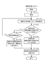
FIG. 6 is a flowchart illustrating an example of the operation of the
省電力状態504に移行した画像処理コントローラ102において、スリープ復帰要因が発生した場合、電源制御部217は、CPU201などへ電力の供給を再開する。これにより、画像処理コントローラ102が省電力状態504からスタンバイ状態502に復帰する。なお、スリープ復帰要因としては、例えば、ユーザが不図示のスリープ復帰ボタンを押下した、クライアントコンピュータ101からジョブを受信した、画像形成装置103からネットワークアクセスを受け付けたことなどが該当する。電力が供給されたCPU201は、メモリ202に展開されたプログラムを実行することにより、図6のフローチャートに従って処理を実行する。
In the
電力が供給されたCPU201は、まず起動処理を行う(S701)。この起動処理では、メモリ202に保存された画像処理コントローラ102の状態を用いて、画像処理コントローラ102を省電力状態504に移行する前の状態に戻す。そして、CPU201は、ネットワークI/F205を介して画像形成装置103へ状態要求コマンドを送信する(S702)。画像形成装置103への状態要求コマンドは、画像処理コントローラ102が現在の画像形成装置103の状態情報を取得・送信することを要求するコマンドである。画像形成装置103への状態要求コマンドは、制御ケーブル111を介して画像形成装置103に送信される。
The
次に、CPU201は、上記S702で送信した状態要求コマンドを画像形成装置103が受け取ったことを示す応答(例えばTCPのACK)を、画像形成装置103から受信したか否かを判定する(703)。そして、上記状態要求コマンドを画像形成装置103が受け取ったことを示す応答を受信したと判定した場合(S703でYesの場合)、CPU201は、画像形成装置103からの状態情報データの受信を待つ(S704)。
Next, the
そして、画像形成装置103からの状態情報データを受信したと判定した場合(S704でYesの場合)、CPU201は、該受信した画像形成装置103からの状態情報データをHDD203に保存する(S705)。次に、CPU201は、画像形成装置103に受信完了通知を送信する(S706)。
If it is determined that the status information data from the
さらに、CPU201は、画像形成装置103に受信完了通知を送信したことに応じて、画像処理コントローラ102が保持する画像形成装置情報の更新作業を行う(S707)。なお、S707の画像形成装置情報の更新作業の詳細は、後述する図7に示す。
Further, the
なお、上記S703において、上記状態要求コマンドを画像形成装置103が受け取ったことを示す応答を受信していないと判定した場合(S703でNoの場合)、CPU201は、S708に処理を移行する。S708では、CPU201は、画像形成装置103に状態要求コマンドを送信して所定時間が経過したか否かを判定する。そして、まだ所定時間が経過していないと判定した場合(S708でNoの場合)、CPU201は、再度、ネットワークI/F205を介して画像形成装置103へ状態要求コマンドを送信する(S702)。一方、所定時間が経過したと判定した場合(S708でYesの場合)、CPU201は、画像形成装置103の状態情報データを受信することなく、S707に処理を移行する。
If it is determined in S703 that a response indicating that the
また、上記S704において、画像形成装置103からの状態情報データを受信していないと判定した場合(S704でNoの場合)、CPU201は、S709に処理を移行する。S709では、CPU201は、上記状態要求コマンドを画像形成装置103が受け取ったことを示す応答を受信してから、所定時間が経過したか否かを判定する。そして、まだ所定時間が経過していないと判定した場合(S709でNoの場合)、CPU201は、S704に処理を移行する。一方、所定時間が経過したと判定した場合(S709でYesの場合)、CPU201は、画像形成装置103の状態情報データを受信することなく、S707に処理を移行する。
If it is determined in S704 that the status information data from the
<画像処理コントローラがもつ画像形成装置の情報更新作業>
以下、図7を参照して、実施例1において、画像処理コントローラ102が保持する画像形成装置情報の更新作業(図6のS707)の動作について説明する。
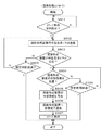
図7は、実施例1において画像処理コントローラ102が省電力状態504から復帰した場合において、画像処理コントローラ102が保持する画像形成装置情報の更新作業(図6のS707)の動作の一例を示すフローチャートである。なお、図7に示すフローチャートの処理は、メモリ202に展開されたプログラムをCPU201が実行することにより実現される。
<Operation of updating information of image forming apparatus possessed by image processing controller>
Hereinafter, the operation of updating the image forming apparatus information held by the image processing controller 102 (S707 in FIG. 6) in the first embodiment will be described with reference to FIG.
FIG. 7 is a flowchart illustrating an example of an operation of updating the image forming apparatus information (S707 in FIG. 6) held by the
CPU201は、HDD203に保持されるスタンバイ状態502から省電力状態504への移行時、及び、省電力状態504からスタンバイ状態502への移行時にそれぞれ受信した画像形成装置103の状態情報データを確認する(S801)。なお、スタンバイ状態502から省電力状態504への移行時に受信した画像形成装置103の状態情報データは、図5のS604で受信されS605で保存されたスリープ前の状態情報データに対応する。また、省電力状態504からスタンバイ状態502への移行時に受信した画像形成装置103の状態情報データは、図6のS704で受信されS705で保存されたスリープ後の状態情報データに対応する。
The
そして、画像形成装置103の状態情報データが両方とも揃っていると判定した場合(S801でYesの場合)、CPU201は、画像形成装置103から両方の状態情報データを比較する(S802)。
If it is determined that both the state information data of the
次に、CPU201は、上記S802の比較結果のうち、相違があるもの(変更点)だけを抽出し、比較結果の分析を行う(S803)。そして、CPU201は、上記S803の分析結果から、変更点の更新作業方法を決定する(S804)。
Next, the
変更点がないと判定した場合(S804で「変更点なし」の場合)、CPU201は、画像処理コントローラ102が保持する画像形成装置情報の更新作業を行わずに、そのまま復帰する(S805)。
When it is determined that there is no change point (in the case of “no change point” in S804), the
また、変更点の中に再起動が必要なものがないと判定した場合(S804で「再起動不要な変更点だけ」の場合)、CPU201は、変更点に合わせて一つずつ情報更新を行う(S806)。
If it is determined that there are no changes that need to be restarted (in the case of “only changes that do not require restart” in S804), the
なお、「再起動不要な変更点」とは、具体的な例としては、以下の(1)〜(5)のようなものがある。
(1)給紙段情報(用紙種類、用紙サイズ)の変更。
(2)用紙残量の変更。
(3)トナー残量の変更。
(4)ロケーション情報(設置場所)の変更。
(5)排紙情報(出力ビンに用紙あり、用紙なし、満載)の変更。
The “changes that do not require restart” include the following (1) to (5) as specific examples.
(1) Change of paper feed stage information (paper type, paper size).
(2) Changing the remaining amount of paper.
(3) Change of remaining toner amount.
(4) Change of location information (installation location).
(5) Change of paper discharge information (paper in output bin, no paper, full).
また、変更点の中に再起動が必要なものがあると判定した場合(S804で「再起動必要な変更点あり」の場合)、CPU201は、画像処理コントローラ102全体を再起動し、画像処理コントローラ102の全情報をリセットする(S807)。
なお、「再起動必要な変更点」とは、具体的な例としては、以下の(1)〜(2)のようなものがある。
(1)フィニッシャ110の種類変更。
(2)フィニッシャ110の設定値変更。
If it is determined that there is a change that needs to be restarted (in the case of “there is a change that needs to be restarted” in S804), the
The “changes that need to be restarted” include the following (1) to (2) as specific examples.
(1) The type of
(2) Change the setting value of the
そして、S805、S806またはS807の処理を終了すると、CPU201は、ネットワークI/F204を開放し、CPU201によるネットワーク113を介した外部との通信を可能にし(S808)、本フローチャートの処理を終了する。ネットワークI/F204は省電力状態504では特定のデータ(ジョブ等)を受信した場合にのみCPU201に通知するようにデータの入出力を制限する動作モードで動作している。そのようなデータの入出力を制限する動作モードから、データの入出力を自由にし、CPU201の制御によるネットワーク113を介した通信が可能な動作モードに変更することを、「ネットワークI/F204を開放する」という。即ち、CPU201は、前記変更点の更新を完了した後に、スタンバイ状態における外部との通信を開始する。
When the processing of S805, S806, or S807 ends, the
なお、画像処理コントローラ102のHDD203等に、予め前記変更点ごとに更新方法を紐付けた更新方法指示情報(ルールブック)を記憶しておく。そして、CPU201は、前記変更点に対応する更新方法を前記更新方法指示情報から取得して、画像形成装置情報の更新方法を決定するように構成してもよい。
Note that update method instruction information (rule book) in which an update method is associated with each change point is stored in advance in the
<画像処理コントローラが省電力状態504に移行する場合と省電力状態504から復帰する場合の画像形成装置の動作説明>
まず、図8を参照して、実施例1において、画像処理コントローラ102が省電力状態504に移行する場合と省電力状態504から復帰する場合の画像形成装置103の動作を説明する。
<Description of Operation of Image Forming Apparatus when Image Processing Controller Transitions to
First, the operation of the
図8は、実施例1において画像処理コントローラ102が省電力状態504に移行する場合と省電力状態504から復帰する場合における画像形成装置103の動作を例示するフローチャートである。なお、図8に示したフローチャートの処理は、メモリ209に展開されたプログラムをCPU208が実行することにより実現される。
FIG. 8 is a flowchart illustrating the operation of the
まず、CPU208は、画像処理コントローラ102から送信される画像形成装置103への状態要求コマンドの受信を監視し、画像形成装置103の状態要求コマンドが受信されたか否かを判定する(S901)。そして、画像形成装置103の状態要求コマンドを受信していないと判定した場合(S901でNoの場合)、CPU208は、画像形成装置103の状態要求コマンドを受信するまでS901の処理を繰り返す。
First, the
一方、画像処理コントローラ102からの画像形成装置103の状態要求コマンドを受信したと判定した場合(S901でYesの場合)、CPU208は、S902に処理を移行する。S902では、CPU208は、画像処理コントローラ102に対して、上記状態要求コマンドを画像形成装置103が受け取ったことを示す応答(例えばTCPのACK)を送信する。
On the other hand, if it is determined that the status request command for the
次に、CPU208は、画像形成装置103の状態情報データを作成する(S903)。このS903では、CPU208は、メモリ209やHDD211内に保持されている画像形成装置103の各種情報から状態情報データを作成する。メモリ209やHDD211には、画像形成装置103の各種情報として、例えば、以下の(1)〜(5)のような情報が保持されており、これらの情報から状態情報データを作成する。
(1)フィニッシャ110の種類。
(2)フィニッシャ110の設定値。
(3)給紙段情報(用紙種類、用紙サイズ)。
(4)用紙残量。
(5)トナー残量。
(6)ロケーション(設置場所)
(7)排紙情報(出力ビン、用紙あり、なし、満載)。
Next, the
(1) The type of
(2) Set value of
(3) Paper feed stage information (paper type, paper size).
(4) Remaining paper amount.
(5) Toner remaining amount.
(6) Location (installation location)
(7) Paper discharge information (output bin, paper present, none, full).
次に、CPU208は、上記S903で作成した状態情報データを、画像処理コントローラ102に送信し(S904)、本フローチャートの処理を終了する。
Next, the
以上のように、画像処理コントローラ102の省電力中に画像形成装置103の構成に変更が発生した場合でも、画像処理コントローラ102の復帰時等に、画像処理コントローラ102が画像形成装置103の構成の変更点を反映する。これにより、画像形成システム全体の情報の統一性を図ることができ、画像形成システム全体の情報の統一性が崩れることによって発生する誤動作を防止することができる。
As described above, even when a change occurs in the configuration of the
上記実施例1では、省電力状態504に移行する場合および省電力状態504から復帰する場合に、画像処理コントローラ102が画像形成装置情報を取得して画像処理コントローラ102が保持する画像形成装置情報を更新させる例について説明した。しかし、本発明はこの実施例に限らず、画像形成システム全体の情報の統一性を図ることができるものであれば、他の実施例でもよい。以下、本発明の実施例2を説明する。
In the first embodiment, the
実施例2では、画像処理コントローラ102が省電力状態504に移行する場合および省電力状態504から復帰する場合に、画像形成装置103自身が画像形成装置情報を保持しておく。そして、画像処理コントローラ102が省電力状態504から復帰する場合に、画像形成装置103が変更点を比較・分析し、画像処理コントローラ102に画像形成装置情報の更新方法を指示するように構成する。
In the second exemplary embodiment, when the
以下、図9を参照して、実施例2において画像処理コントローラ102が省電力状態504に移行する場合の画像処理コントローラ102の動作を説明する。
図9は、実施例2において画像処理コントローラ102が省電力状態504に移行する場合の画像処理コントローラ102の動作の一例を示すフローチャートである。なお、図9に示すフローチャートの処理は、メモリ202に展開されたプログラムをCPU201が実行することにより実現される。なお、図5と同一のステップには同一のステップ番号を付し、詳細な説明は省略する。
The operation of the
FIG. 9 is a flowchart illustrating an example of the operation of the
画像処理コントローラ102がジョブを実行した後など画像処理コントローラ102がスタンバイ状態502に移行すると、CPU201は、スリープ移行要因の発生を監視する(S601)。CPU201は、スリープ移行要因を検出したと判定した場合(SS601でYesの場合)、S1001に処理を移行する。
When the
S1001では、CPU201は、ネットワークI/F205を介して、画像形成装置103へスリープ移行通知パケットを送信する。なお、スリープ移行通知パケットは、画像形成装置103に、画像処理コントローラ102が省電力状態504に移行することを知らせるパケットである。画像形成装置103へのスリープ移行通知パケットは、制御ケーブル111を介して画像形成装置103に送信される。
In step S <b> 1001, the
次に、CPU201は、上記S602で送信したスリープ移行通知パケットを画像形成装置103が受け取ったことを示す応答(例えばTCPのACK)を、画像形成装置103から受信したか否かを判定する(S1002)。そして、上記スリープ移行通知パケットを画像形成装置103が受け取ったことを示す応答を受信したと判定した場合(S1002でYesの場合)、CPU201は、S607に処理を移行する。S607では、CPU201は、画像処理コントローラ102をスタンバイ状態502から省電力状態504に移行させる。
Next, the
なお、上記S1002において、上記スリープ移行通知パケットを画像形成装置103が受け取ったことを示す応答を受信していないと判定した場合(S1002でNoの場合)、CPU201は、S1003に処理を移行する。S1003では、CPU201は、画像形成装置103にスリープ移行通知パケットを送信して所定時間が経過したか否かを判定する。そして、まだ所定時間が経過していないと判定した場合(S1003でNoの場合)、CPU201は、再度、ネットワークI/F205を介して画像形成装置103へスリープ移行通知パケットを送信する(S1001)。一方、所定時間が経過したと判定した場合(S1003でYesの場合)、CPU201は、画像処理コントローラ102を省電力状態504に移行せず、本フローチャートの処理を終了する。
If it is determined in S1002 that a response indicating that the
<画像処理コントローラが省電力状態から復帰するときの画像処理コントローラの動作説明>
次に、図10を参照して、実施例2における画像処理コントローラ102が省電力状態504からスタンバイ状態502に移行した場合の画像処理コントローラ102の動作について説明する。
<Description of the operation of the image processing controller when the image processing controller returns from the power saving state>
Next, the operation of the
図10は、実施例2における画像処理コントローラ102が省電力状態から復帰する場合の画像処理コントローラ102の動作の一例を示すフローチャートである。なお、図10に示すフローチャートの処理は、メモリ202に展開されたプログラムをCPU201が実行することにより実現される。なお、図5と同一のステップには同一のステップ番号を付し、詳細な説明は省略する。
FIG. 10 is a flowchart illustrating an example of the operation of the
スリープ復帰要因が発生し、電力が供給されたCPU201は、図10のフローチャートに従って処理を実行する。CPU201は、起動処理(S701)の後、ネットワークI/F205を介して画像形成装置103に対して、スリープ復帰通知パケットを送信する(S1101)。なお、画像処理コントローラ102のスリープ復帰通知パケットは、画像処理コントローラ102が省電力状態504から復帰することを通知するパケットである。
The
次に、CPU201は、画像処理コントローラ102が保持する画像形成装置情報の更新要求コマンド(更新指示)を、画像形成装置103から受信したかどうかを判定する(S1102)。そして、上記画像形成装置情報の更新要求コマンドを画像形成装置103から受信したと判定した場合(S1002でYesの場合)、CPU201は、S1103に処理を移行する。S1103では、CPU201は、画像形成装置103に対して、上記画像形成装置情報の更新要求コマンドを画像処理コントローラ102が受け取ったことを示す応答(受信完了通知)を送信し、S1106に処理を移行する。
Next, the
S1106では、CPU201は、上記S1102で受信した画像処理コントローラ102が保持する画像形成装置情報の更新要求コマンドに従い、画像処理コントローラ102の画像形成装置情報の更新作業を行う。
In step S <b> 1106, the
なお、上記S1002において、上記画像形成装置情報の更新要求コマンドを画像形成装置103から受信していないと判定した場合(S1002でNoの場合)、CPU201は、S1104に処理を移行する。S1104では、CPU201は、画像形成装置103にスリープ復帰通知を送信して所定時間が経過したか否かを判定する。そして、まだ所定時間が経過していないと判定した場合(S1104でNoの場合)、CPU201は、再度、ネットワークI/F205を介して画像形成装置103へスリープ復帰通知を送信する(S1101)。一方、所定時間が経過したと判定した場合(S1104でYesの場合)、CPU201は、S1105に処理を移行する。S1105では、CPU201は、画像処理コントローラ102が保持する画像形成装置情報の更新要求コマンドを受信せずに、更新方法結果通知の内容を再起動と書き換えて、S1106に処理を移行する。
If it is determined in S1002 that the image forming apparatus information update request command has not been received from the image forming apparatus 103 (No in S1002), the
<画像処理コントローラが省電力状態に移行するときの画像形成装置の動作説明>
以下、図11を参照して、実施例2において、画像処理コントローラ102が省電力状態504に移行する場合の画像形成装置103の動作を説明する。
図11は、実施例2において画像処理コントローラ102が省電力状態504に移行する場合の画像形成装置103の動作の一例を示すフローチャートである。なお図8に示したフローチャートの処理は、メモリ209に展開されたプログラムをCPU208が実行することにより実現される。
<Description of Operation of Image Forming Apparatus when Image Processing Controller Transitions to Power Saving State>
Hereinafter, the operation of the
FIG. 11 is a flowchart illustrating an example of the operation of the
まず、CPU208は、画像処理コントローラ102から送信されるスリープ移行通知パケットの受信を監視し、スリープ移行通知パケットが受信されたか否かを判定する(S1201)。そして、画像処理コントローラ102からスリープ移行通知パケットを受信していないと判定した場合(S1201でNoの場合)、CPU208は、スリープ移行通知パケットを受信するまでS1201の処理を繰り返す。
First, the
一方、画像処理コントローラ102からスリープ移行通知パケットを受信したと判定した場合(S1001でYesの場合)、CPU208は、S1002に処理を移行する。S1002では、CPU208は、画像処理コントローラ102に対して、上記スリープ移行通知パケットを画像形成装置103が受け取ったことを示す応答(例えばTCPのACK)を送信する。
On the other hand, when it is determined that the sleep transition notification packet has been received from the image processing controller 102 (Yes in S1001), the
次に、CPU208は、メモリ209やHDD211内に保持されている画像形成装置103の各種情報から画像形成装置103の状態情報データを作成する(S1203)。なお、S1203の処理は、図8のS903と同一の処理であるので詳細な説明は省略する。
次に、CPU208は、作成した状態情報データをHDD211に保持し(S1204)、本フローチャートの処理を終了する。
Next, the
Next, the
<画像処理コントローラが省電力状態から復帰するときの画像形成装置の動作説明>
図12を参照して、実施例2における、画像処理コントローラ102が省電力状態504から復帰する場合の画像形成装置103の動作を説明する。
図12は、実施例2における画像処理コントローラ102が省電力状態504から復帰する場合の画像形成装置103のフローチャートである。なお、図12に示したフローチャートの処理は、メモリ209に展開されたプログラムをCPU208が実行することにより実現される。
<Description of Operation of Image Forming Apparatus when Image Processing Controller Returns from Power Saving State>
With reference to FIG. 12, the operation of the
FIG. 12 is a flowchart of the
まず、CPU208は、画像処理コントローラ102から送信されるスリープ復帰通知パケットの受信を監視し、スリープ復帰通知パケットが受信されたか否かを判定する(S1301)。そして、スリープ復帰通知パケットを受信していないと判定した場合(S1301でNoの場合)、CPU208は、スリープ復帰通知パケットを受信するまでS1301の処理を繰り返す。
First, the
一方、画像処理コントローラ102からのスリープ復帰通知パケットを受信したと判定した場合(S1301でYesの場合)、CPU208は、S1302に処理を移行する。S1302では、CPU208は、画像処理コントローラ102に対して、上記スリープ復帰通知パケットを画像形成装置103が受け取ったことを示す応答(例えばTCPのACK)を送信する。
On the other hand, if it is determined that the sleep return notification packet has been received from the image processing controller 102 (Yes in S1301), the
次に、CPU208は、メモリ209やHDD211内に保持されている画像形成装置103の各種情報から画像形成装置103の状態情報データを作成する(S1303)。なお、S1303の処理は、図8のS903と同一の処理であるので詳細な説明は省略する。次に、CPU208は、上記S1303で作成した状態情報データをHDD211に保持する(S1304)。
Next, the
次に、CPU208は、画像処理コントローラ102が省電力状態に移行、又は省電力状態から復帰の際に作成した画像形成装置の状態情報データを用いて画像処理コントローラ102が保持する画像形成装置情報の更新方法を決定する(S1305)。なお、S1305の処理の詳細は後述する図13に示す。
Next, the
さらに、CPU208は、上記S1305で決定した結果(画像処理コントローラ102が保持する画像形成装置情報の更新方法)を、更新要求コマンド(更新指示)として、画像処理コントローラ102に通知する(S1306)。そして、本フローチャートの処理を終了する。
Further, the
<画像処理コントローラが保持する画像形成装置の情報更新作業の決定動作>
以下、図13を参照して、実施例2のおける、画像処理コントローラ102が保持する画像形成装置情報更新方法の決定動作(図12のS1305)について説明する。
図13は、実施例2の画像形成装置103が実行する画像処理コントローラ102の画像形成装置情報の更新方法の決定動作の一例を示すフローチャートである。なお、図13に示したフローチャートの処理は、メモリ209に展開されたプログラムをCPU208が実行することにより実現される。
<Determination Operation of Information Update Work of Image Forming Apparatus Held by Image Processing Controller>
Hereinafter, the determination operation (S1305 in FIG. 12) of the image forming apparatus information update method held by the
FIG. 13 is a flowchart illustrating an example of a determination operation of the image forming apparatus information update method of the
CPU208は、HDD211に保持される画像処理コントローラ102の省電力状態504への移行時、及び、スタンバイ状態502への移行時にそれぞれ作成した画像形成装置103の状態情報データを比較する(S1401)。なお、画像処理コントローラ102の省電力状態504への移行時に作成した画像形成装置103の状態情報データとは、図11のS1203で作成されS1204で保存されたものである。また、画像処理コントローラ102のスタンバイ状態502への移行時に作成した画像形成装置103の状態情報データとは、図12のS1303で作成されS1304で保存されたものである。
The
次に、CPU208は、上記S1401の比較結果のうち、相違があるもの(変更点)だけを抽出し、該抽出した変更点の比較結果の分析を行う(S1402)。そして、CPU208は、上記S1402の分析結果から、変更点の更新作業方法を決定する(S1403)。
Next, the
変更点がないと判定した場合(S1403で「変更点なし」の場合)、CPU208は、更新方法の結果に「なにもせず」をセットし(S1404)、本フローチャートの処理を終了する。
When it is determined that there is no change point (in the case of “no change point” in S1403), the
また、変更点の中に再起動が必要なものがないと判定した場合(S1403で「再起動不要な変更点だけ」の場合)、CPU208は、更新方法の結果に「変更点のみ更新」をセットする(S1405)。この場合、変更点に対応する画像形成装置103の状態情報データも更新要求コマンドのパラメータにセットする。そして、本フローチャートの処理を終了する。なお、「再起動不要な変更点」の具体例は、実施例1での説明とおりである。
If it is determined that there are no changes that need to be restarted (in the case of “only changes that do not require restart” in S1403), the
また、変更点の中に再起動が必要なものがあると判定した場合(S1403で「再起動必要な変更点あり」の場合)、CPU208は、更新方法の結果に「再起動」をセットし(S1406)、本フローチャートの処理を終了する。なお、「再起動要な変更点」の具体例は、実施例1での説明とおりである。
If it is determined that some of the changes need to be restarted (in the case of “There are changes that need to be restarted” in S1403), the
なお、画像形成装置103のHDD211等に、予め前記変更点ごとに更新方法を紐付けた更新方法指示情報(ルールブック)を記憶しておく。そして、CPU208は、前記変更点に対応する更新方法を前記更新方法指示情報から取得して、画像形成装置情報の更新方法を決定するように構成してもよい。
Note that update method instruction information (rule book) in which an update method is associated with each change point is stored in advance in the
以上のように、図13のS1404、S1405又はS1406で決定された更新方法が、図12のS1306において、画像形成装置情報の更新要求コマンドとして、画像処理コントローラ102に通知される。この画像形成装置情報の更新要求コマンドに基づいて、画像処理コントローラ102は、図10のS1106において、画像処理コントローラ102の画像形成装置情報の更新作業を行う。
As described above, the update method determined in S1404, S1405, or S1406 in FIG. 13 is notified to the
例えば、更新方法が「なにもせず」に該当する更新要求コマンドの場合、画像処理コントローラ102のCPU201は、画像処理コントローラ102が保持する画像形成装置情報の更新作業を行わずに、そのまま復帰する。また、更新方法が「変更点のみ更新」に該当する更新要求コマンドの場合、画像処理コントローラ102のCPU201は、変更点に合わせて一つずつ情報更新を行う。また、更新方法が「再起動」に該当する更新要求コマンドの場合、画像処理コントローラ102のCPU201は、画像処理コントローラ102全体を再起動し、画像処理コントローラ102の全情報をリセットする。
For example, in the case of an update request command in which the update method corresponds to “do nothing”, the
実施例2によれば、画像処理コントローラ102の省電力中に画像形成装置103の構成に変更が発生した場合でも、画像処理コントローラ102の復帰時等に画像形成装置103が自身で構成の変更点を比較分析し、画像処理コントローラ102に反映する。これにより、画像形成システム全体の情報の統一性を図ることができ、画像形成システム全体の情報の統一性が崩れることによって発生する誤動作を防止することができる。
According to the second embodiment, even when a change occurs in the configuration of the
実施例1では、画像処理コントローラ102が省電力状態504に移行する場合および復帰する場合に、画像形成装置103の情報を取得してそれを比較して画像処理コントローラ102がもつ画像形成装置情報を更新させる例について説明した。
しかし、本発明はこの実施例に限らない。変更点が再起動必要な場合であって、スタンバイ状態502に移行時に到達した印刷ジョブや画像処理コントローラ102へのアクセスについて、画像形成装置情報の変更に影響を受けないものに関しては、変更点の更新より先に処理してもよい。以下、この実施例について説明する。
In the first exemplary embodiment, when the
However, the present invention is not limited to this embodiment. If the change needs to be restarted and the access to the print job or the
以下、図14を参照して、画像処理コントローラ102が省電力状態504からスタンバイ状態502に復帰した場合に画像形成装置情報の変更点において再起動が必要な場合の動作について説明する。
図14は、実施例3において画像処理コントローラ102が省電力状態504から復帰した場合において、画像処理コントローラ102が保持する画像形成装置情報の更新作業(図6のS707)の一例を示すフローチャートである。なお、図14に示すフローチャートの処理は、メモリ202に展開されたプログラムをCPU201が実行することにより実現される。また、図7と同一のステップには同一のステップ番号を付してあり、説明を省略する。
Hereinafter, with reference to FIG. 14, an operation when the
FIG. 14 is a flowchart illustrating an example of the update operation (S707 in FIG. 6) of the image forming apparatus information held by the
S804において、CPU201は、変更点の中に再起動が必要なものがあると判定した場合(S804で「再起動必要な変更点あり」の場合)、S1501に処理を移行する。
S1501では、CPU201は、画像処理コントローラ102の復帰要因として又は復帰後に画像処理コントローラ102へ到達したアクセスの有無を確認する。
In step S804, if the
In step S <b> 1501, the
そして、画像処理コントローラ102の復帰要因としてのアクセスも、復帰後に到達したアクセスもないと判定した場合(S1501でNoの場合)、CPU201は、S807に処理を移行する。S807では、CPU201は、画像処理コントローラ102全体を再起動し、画像処理コントローラ102の全情報をリセットする。ここでリセットされ変更される情報には、具体的には、例えば(1)フィニッシャ110の種類、(2)フィニッシャ110の設定値のような情報が含まれる。
If the
一方、画像処理コントローラ102の復帰要因としてのアクセス、又は復帰後に到達したアクセスがあると判定した場合(S1501でYesの場合)、CPU201は、S1502に処理を移行する。
On the other hand, when it is determined that there is an access as a return factor of the
S1502では、CPU201は、上記到達したアクセスのジョブ内容を解析する。そして、該到達したアクセスに対応するジョブの処理が、画像処理コントローラ102の再起動に影響を受けるか否かを判定する。
なお、画像処理コントローラ102の再起動に影響を受けるアクセスに対応するジョブの処理には、例えば、(1)再起動しても影響を受けない設定だけを含む印刷ジョブ、(2)再起動しても影響を受けない情報だけを取り出し通知する通知ジョブなどがある。
In step S1502, the
For example, (1) a print job including only settings that are not affected by restart, (2) restart, for processing of a job corresponding to an access that is affected by restart of the
また、(1)再起動しても影響を受けない設定だけを含む印刷ジョブには、(I)フィニッシャ110を利用しない印刷ジョブ、(II)画像形成装置103のHDD211に保存する印刷ジョブ等が含まれる。
また、(2)再起動しても影響を受けない情報だけを取り出し通知する通知ジョブには、(III)画像形成装置103がもつ用紙種情報取得の通知ジョブ、(IV)画像形成装置103の名称取得の通知ジョブのようなものがある。
In addition, (1) print jobs including only settings that are not affected by restart include (I) print jobs not using the
Also, (2) a notification job for extracting and notifying only information that is not affected even after restarting includes (III) a notification job for acquiring paper type information possessed by the
そして、上記到達したアクセスに対応するジョブの処理が、画像処理コントローラ102の再起動に影響を受けないと判定した場合(S1503でNoの場合)、CPU201は、S1504に処理を移行する。S1504では、CPU201は、上記到達したアクセスに対応するジョブを先に処理し、該到達したアクセスに対応するジョブの処理が終了するまで待ち、S807に移行し、画像処理コントローラ102を再起動する。
If it is determined that the job processing corresponding to the reached access is not affected by the restart of the image processing controller 102 (No in S1503), the
一方、上記到達したアクセスに対応するジョブの処理が、画像処理コントローラ102の再起動に影響を受けると判定した場合(S1503でYesの場合)、CPU201は、S1505に処理を移行する。S1505では、CPU201は、上記到達したアクセスに対応するジョブをキャンセルし、S807に移行し、画像処理コントローラ102を再起動する。
On the other hand, if it is determined that the job process corresponding to the reached access is affected by the restart of the image processing controller 102 (Yes in S1503), the
実施例3によれば、画像処理コントローラ102の省電力中に画像形成装置103の構成に画像処理コントローラ102の再起動が必要な変更が発生し、再起動による情報のリセットに影響を受けないジョブが到達した場合には、該ジョブの処理を先に実行する。これにより、画像形成システム全体の情報の統一性が崩れることによって発生する誤動作を防止しつつ、ジョブを迅速に処理することができる。
According to the third exemplary embodiment, a job that does not affect the resetting of information due to a restart occurs when the configuration of the
実施例1では、画像処理コントローラ102が省電力状態504に移行する場合および復帰する場合に、画像形成装置103の情報を取得してそれを比較して画像処理コントローラ102がもつ画像形成装置情報を更新させる例について説明した。
しかし、本発明はこの実施例に限らない。変更点が再起動不要な場合であって、スタンバイ状態502に移行時に到達した印刷ジョブや画像処理コントローラ102へのアクセスについて、画像形成装置情報の変更に影響を受けないものに関しては、変更点の更新より先に処理してもよい。以下、この実施例について説明する。
In the first exemplary embodiment, when the
However, the present invention is not limited to this embodiment. When the change is not required to be restarted and the access to the print job or the
以下、図15を参照して、画像処理コントローラ102が省電力状態504からスタンバイ状態502に復帰した場合に画像形成装置情報の変更点において再起動が不要な場合、即ち、変更点のみ更新(図7のS808)の動作について説明する。
図15は、実施例4において画像処理コントローラ102が省電力状態504から復帰した場合において、画像形成装置情報の変更点において再起動が不要な場合、即ち、変更点のみ更新(図7のS808)の動作の一例を示すフローチャートである。なお、図15に示すフローチャートの処理は、メモリ202に展開されたプログラムをCPU201が実行することにより実現される。
Hereinafter, with reference to FIG. 15, when the
FIG. 15 illustrates the case where the
まず、CPU201は、画像処理コントローラ102が保持する画像形成装置情報の変更点の更新中に画像処理コントローラ102へ到達したアクセスの有無を確認する(S1601)。
そして、画像形成装置情報の変更点更新中にアクセスがないと判定した場合(S1601でNoの場合)、CPU201は、画像形成装置情報の変更点の中から未更新のものを一つ抽出して更新を行う(S1602)。
First, the
If it is determined that there is no access during the update of the change in the image forming apparatus information (No in S1601), the
次に、CPU201は、画像形成装置情報の変更点の更新の有無を確認し(S1603)、未更新の変更点がまだあるか否かを判定する(S1604)。そして、未更新の変更点がまだあると判定した場合(S1604でYesの場合)、CPU201は、S1601に処理を移行する。一方、未更新の変更点がないと判定した場合(S1604でNoの場合)、CPU201は、本フローチャートの処理を終了する。
Next, the
また、上記S1601にて、CPU201は、画像処理コントローラ102が保持する画像形成装置情報の変更点の更新中に画像処理コントローラ102へ到達したアクセスがあると判定した場合(S1601でYesの場合)、S1605に処理を移行する。
In S1601, the
S1605では、CPU201は、上記到達したアクセスのジョブ内容を解析する。そして、CPU201は、該到達したアクセスに対応するジョブの処理が、画像形成装置情報の変更点更新に影響を受けるか否かを判定する(S1606)。
なお、画像形成装置情報の変更点の更新に影響を受けるアクセスに対応するジョブの処理には、例えば以下の(1)〜(2)のようなものがある。
(1)画像形成装置情報の変更点の更新に影響を受ける設定を含む印刷ジョブの処理。(2)画像形成装置情報の変更点の更新に影響を受ける情報を取り出す通知ジョブの処理。
In step S1605, the
Note that, for example, the following (1) and (2) include the job processing corresponding to the access affected by the update of the change in the image forming apparatus information.
(1) Processing of a print job including a setting that is affected by update of a change in image forming apparatus information. (2) Notification job processing for retrieving information affected by the update of the change in the image forming apparatus information.
そして、上記到達したアクセスに対応するジョブの処理が、画像形成装置情報の変更点更新に影響があると判定した場合(S1606でYesの場合)、CPU201は、先に、画像形成装置情報の変更点の更新を行うべく、S1602に処理を移行する。
When it is determined that the job processing corresponding to the reached access has an influence on the update of the image forming apparatus information change point (Yes in S1606), the
一方、上記到達したアクセスに対応するジョブの処理が、画像形成装置情報の変更点更新に影響を受けないと判定した場合(S1606でNoの場合)、CPU201は、該到達したアクセスに対応するジョブを先に処理する(S1607)。そして、該アクセスに対応するジョブの処理が終了した後に、CPU201は、S1602に処理を移行して、画像形成装置情報の変更点の更新を行う。
On the other hand, if it is determined that the processing of the job corresponding to the reached access is not affected by the update of the image forming apparatus information change (No in S1606), the
実施例4によれば、画像処理コントローラ102の省電力中に画像形成装置103の構成に画像処理コントローラ102の再起動が不必要な変更が発生し、該変更の更新に影響を受けないジョブが到達した場合には、該ジョブの処理を先に実行する。これにより、画像形成システム全体の情報の統一性が崩れることによって発生する誤動作を防止しつつ、ジョブを迅速に処理することができる。
According to the fourth exemplary embodiment, a change that does not require restart of the
<各実施例の効果>
本発明の各実施例では、画像処理コントローラ102が省電力状態504に移行する前に、画像形成装置103の状態情報を保存しておく。そして、画像処理コントローラ102がスタンバイ状態502から復帰したときの画像形成装置103の状態情報と、省電力状態移行時と復帰時の画像形成装置103の状態情報とを比較する。そして、それらの差分(変更点)を、該変更点に基づく更新方法により、画像処理コントローラ102が保持する画像形成装置103の情報を適宜反映する。これにより、画像形成システム全体の情報の統一性を保つことができ、画像形成システム全体の情報の統一性が崩れることによって発生する誤動作を防止することができる。
<Effect of each embodiment>
In each embodiment of the present invention, the state information of the
なお、上述した各種データの構成及びその内容はこれに限定されるものではなく、用途や目的に応じて、様々な構成や内容で構成されることは言うまでもない。
以上、一実施形態について示したが、本発明は、例えば、システム、装置、方法、プログラムもしくは記憶媒体等としての実施態様をとることが可能である。具体的には、複数の機器から構成されるシステムに適用しても良いし、また、一つの機器からなる装置に適用しても良い。
また、上記各実施例を組み合わせた構成も全て本発明に含まれるものである。
It should be noted that the configuration and contents of the various data described above are not limited to this, and it goes without saying that the various data and configurations are configured according to the application and purpose.
Although one embodiment has been described above, the present invention can take an embodiment as, for example, a system, apparatus, method, program, or storage medium. Specifically, the present invention may be applied to a system composed of a plurality of devices, or may be applied to an apparatus composed of a single device.
Moreover, all the structures which combined said each Example are also contained in this invention.
(他の実施例)
また、本発明は、以下の処理を実行することによっても実現される。即ち、上述した実施形態の機能を実現するソフトウェア(プログラム)を、ネットワーク又は各種記憶媒体を介してシステム或いは装置に供給し、そのシステム或いは装置のコンピュータ(またはCPUやMPU等)がプログラムを読み出して実行する処理である。
また、本発明は、複数の機器から構成されるシステムに適用しても、1つの機器からなる装置に適用してもよい。
本発明は上記実施例に限定されるものではなく、本発明の趣旨に基づき種々の変形(各実施例の有機的な組合せを含む)が可能であり、それらを本発明の範囲から除外するものではない。即ち、上述した各実施例及びその変形例を組み合わせた構成も全て本発明に含まれるものである。
(Other examples)
The present invention can also be realized by executing the following processing. That is, software (program) that realizes the functions of the above-described embodiments is supplied to a system or apparatus via a network or various storage media, and a computer (or CPU, MPU, or the like) of the system or apparatus reads the program. It is a process to be executed.
Further, the present invention may be applied to a system composed of a plurality of devices or an apparatus composed of a single device.
The present invention is not limited to the above embodiments, and various modifications (including organic combinations of the embodiments) are possible based on the spirit of the present invention, and these are excluded from the scope of the present invention. is not. That is, the present invention includes all the combinations of the above-described embodiments and modifications thereof.
101 クライアントコンピュータ
102 画像処理コントローラ
103 画像処理装置(MFP)
106 MFPコントローラ
201 CPU
204 ネットワークI/F
205 ネットワークI/F
208 CPU
210 ネットワークI/F
101
106
204 Network I / F
205 Network I / F
208 CPU
210 Network I / F
Claims (24)
前記画像処理装置は、
前記画像形成装置から前記画像形成装置の情報を取得する取得手段と、
前記取得手段によって取得された前記画像形成装置の情報を記憶する記憶手段と、
前記外部装置からの要求に従って前記外部装置に前記記憶手段によって記憶された前記画像形成装置の情報を送信する送信手段と、
所定の条件を満たしたことに基づいて前記画像処理装置の状態を第1電力状態から前記第1電力状態より省電力の第2電力状態に移行する移行手段と、
所定の条件を満たしたことに基づいて前記画像処理装置の状態を前記第2電力状態から前記第1電力状態に復帰させる復帰手段と、を有し、
前記復帰手段が前記画像処理装置の状態を前記第2電力状態から前記第1電力状態に復帰させたときに、前記取得手段は、前記画像形成装置から前記画像形成装置の最新の情報を取得し、前記記憶手段は、前記最新の情報で前記情報を更新する、ことを特徴とする画像形成システム。 Generates image data based on the print request sent from an external device via a network, an image processing apparatus sending the created image data, printing based on the image data transmitted from the pre-Symbol image processing apparatus An image forming apparatus comprising:
The image processing apparatus includes:
Obtaining means for obtaining information of the image forming apparatus from the image forming apparatus;
Storage means for storing information of the image forming apparatus acquired by the acquisition means;
Transmitting means for transmitting information on the image forming apparatus stored by the storage means to the external apparatus in accordance with a request from the external apparatus;
Transition means for transitioning the state of the image processing apparatus from the first power state to the power-saving second power state from the first power state based on satisfying a predetermined condition;
Return means for returning the state of the image processing apparatus from the second power state to the first power state based on satisfying a predetermined condition;
When the return unit returns the state of the image processing apparatus from the second power state to the first power state, the acquisition unit acquires the latest information of the image forming apparatus from the image forming apparatus. The image forming system, wherein the storage unit updates the information with the latest information.
前記画像形成装置に接続されているフィニッシャ装置のタイプ、前記フィニッシャ装置の設定値、前記画像形成装置のシート格納部に格納されているシートのサイズ又はタイプ、前記シート格納部に格納されているシートの残量、前記画像形成装置のトナー残量、前記画像形成装置の位置、及び、シートの排出情報、の少なくとも1つを含む、ことを特徴とする請求項1〜9の何れか1項に記載の画像形成システム。 The information of the image forming apparatus is:
The type of the finisher device connected to the image forming apparatus, the setting value of the finisher apparatus, the size or type of the sheet stored in the sheet storage unit of the image forming apparatus, and the sheet stored in the sheet storage unit The remaining amount of toner, the remaining amount of toner in the image forming apparatus, the position of the image forming apparatus, and sheet discharge information are included. The image forming system described.
前記画像形成装置から前記画像形成装置の情報を取得する取得手段と、
前記取得手段によって取得された前記画像形成装置の情報を記憶する記憶手段と、
前記外部装置からの要求に従って前記外部装置に前記記憶手段によって記憶された前記画像形成装置の情報を送信する送信手段と、
所定の条件を満たしたことに基づいて前記画像処理装置の状態を第1電力状態から前記第1電力状態より省電力の第2電力状態に移行する移行手段と、
所定の条件を満たしたことに基づいて前記画像処理装置の状態を前記第2電力状態から前記第1電力状態に復帰させる復帰手段と、を有し、
前記復帰手段が前記画像処理装置の状態を前記第2電力状態から前記第1電力状態に復帰させたときに、前記取得手段は、前記画像形成装置から前記画像形成装置の最新の情報を取得し、前記記憶手段は、前記最新の情報で前記情報を更新する、ことを特徴とする画像処理装置。 An image processing apparatus that generates image data based on a print request transmitted from an external apparatus via a network, and transmits the image data to an image forming apparatus that forms an image on a sheet based on the image data,
Obtaining means for obtaining information of the image forming apparatus from the image forming apparatus;
Storage means for storing information of the image forming apparatus acquired by the acquisition means;
Transmitting means for transmitting information on the image forming apparatus stored by the storage means to the external apparatus in accordance with a request from the external apparatus;
Transition means for transitioning the state of the image processing apparatus from the first power state to the power-saving second power state from the first power state based on satisfying a predetermined condition;
Return means for returning the state of the image processing apparatus from the second power state to the first power state based on satisfying a predetermined condition;
When the return unit returns the state of the image processing apparatus from the second power state to the first power state, the acquisition unit acquires the latest information of the image forming apparatus from the image forming apparatus. The image processing apparatus, wherein the storage unit updates the information with the latest information.
前記画像形成装置に接続されているフィニッシャ装置のタイプ、前記フィニッシャ装置の設定値、前記画像形成装置のシート格納部に格納されているシートのサイズ又はタイプ、前記シート格納部に格納されているシートの残量、前記画像形成装置のトナー残量、前記画像形成装置の位置、及び、シートの排出情報、の少なくとも1つを含む、ことを特徴とする請求項13〜21の何れか1項に記載の画像処理装置。 The information of the image forming apparatus is:
The type of the finisher device connected to the image forming apparatus, the setting value of the finisher apparatus, the size or type of the sheet stored in the sheet storage unit of the image forming apparatus, and the sheet stored in the sheet storage unit The remaining amount of toner, the remaining amount of toner in the image forming apparatus, the position of the image forming apparatus, and the discharge information of the sheet are included in any one of claims 13 to 21. The image processing apparatus described.
前記画像形成装置から前記画像形成装置の情報を取得する第1取得ステップと、
前記第1取得ステップで取得された前記画像形成装置の情報を記憶する記憶ステップと、
前記外部装置からの要求に従って前記外部装置に前記画像形成装置の情報を送信する送信ステップと、
所定の条件を満たしたことに基づいて前記画像処理装置の状態を第1電力状態から前記第1電力状態より省電力の第2電力状態に移行する移行ステップと、
所定の条件を満たしたことに基づいて前記画像処理装置の状態を前記第2電力状態から前記第1電力状態に復帰させる復帰ステップと、
前記復帰ステップが前記画像処理装置の状態を前記第2電力状態から前記第1電力状態に復帰させたときに、前記画像形成装置から前記画像形成装置の最新の情報を取得する第2取得ステップと、
前記第2取得ステップで取得した前記最新の情報で前記情報を更新する更新ステップと、を有することを特徴とする画像処理装置の制御方法。 A control method for an image processing apparatus that generates image data based on a print request transmitted from an external apparatus via a network, and transmits the image data to an image forming apparatus that forms an image on a sheet based on the image data. There,
A first acquisition step of acquiring information of the image forming apparatus from the image forming apparatus;
A storage step for storing information of the image forming apparatus acquired in the first acquisition step;
A transmission step of transmitting information of the image forming apparatus to the external apparatus according to a request from the external apparatus;
A transition step of transitioning the state of the image processing apparatus from the first power state to the power-saving second power state from the first power state based on satisfying a predetermined condition;
A return step of returning the state of the image processing apparatus from the second power state to the first power state based on satisfying a predetermined condition;
A second acquisition step of acquiring the latest information of the image forming apparatus from the image forming apparatus when the returning step returns the state of the image processing apparatus from the second power state to the first power state; ,
And an update step of updating the information with the latest information acquired in the second acquisition step.
Priority Applications (5)
| Application Number | Priority Date | Filing Date | Title |
|---|---|---|---|
| JP2013246933A JP6223152B2 (en) | 2013-11-29 | 2013-11-29 | Image forming system, image processing apparatus, and image processing apparatus control method |
| DE102014223729.7A DE102014223729A1 (en) | 2013-11-29 | 2014-11-20 | PICTURE-GENERATING SYSTEMS AND METHODS THAT USE THEM |
| US14/553,951 US9262102B2 (en) | 2013-11-29 | 2014-11-25 | Image forming systems, and methods of using same |
| US14/992,260 US9843688B2 (en) | 2013-11-29 | 2016-01-11 | Image forming systems, and methods of using same |
| US15/806,206 US10469676B2 (en) | 2013-11-29 | 2017-11-07 | Image forming systems, and methods of using same |
Applications Claiming Priority (1)
| Application Number | Priority Date | Filing Date | Title |
|---|---|---|---|
| JP2013246933A JP6223152B2 (en) | 2013-11-29 | 2013-11-29 | Image forming system, image processing apparatus, and image processing apparatus control method |
Publications (3)
| Publication Number | Publication Date |
|---|---|
| JP2015106771A JP2015106771A (en) | 2015-06-08 |
| JP2015106771A5 JP2015106771A5 (en) | 2017-01-12 |
| JP6223152B2 true JP6223152B2 (en) | 2017-11-01 |
Family
ID=53058639
Family Applications (1)
| Application Number | Title | Priority Date | Filing Date |
|---|---|---|---|
| JP2013246933A Active JP6223152B2 (en) | 2013-11-29 | 2013-11-29 | Image forming system, image processing apparatus, and image processing apparatus control method |
Country Status (3)
| Country | Link |
|---|---|
| US (3) | US9262102B2 (en) |
| JP (1) | JP6223152B2 (en) |
| DE (1) | DE102014223729A1 (en) |
Families Citing this family (6)
| Publication number | Priority date | Publication date | Assignee | Title |
|---|---|---|---|---|
| JP6223152B2 (en) * | 2013-11-29 | 2017-11-01 | キヤノン株式会社 | Image forming system, image processing apparatus, and image processing apparatus control method |
| JP6558177B2 (en) * | 2015-09-24 | 2019-08-14 | セイコーエプソン株式会社 | Device management apparatus, device monitoring system, and device management program |
| US11076055B2 (en) * | 2016-01-19 | 2021-07-27 | Canon Kabushiki Kaisha | Control apparatus detects an error in image processor and reboots the image processor before transmits printing data to printing apparatus |
| US10379788B2 (en) * | 2016-06-10 | 2019-08-13 | Ricoh Company, Ltd. | Operation device configured to display a configuration of an image forming device and information processing system including same |
| JP6828600B2 (en) * | 2016-06-10 | 2021-02-10 | 株式会社リコー | Information processing system, operation device, information processing method and information processing program |
| JP7210238B2 (en) * | 2018-11-15 | 2023-01-23 | キヤノン株式会社 | Information processing device, control method for information processing device, and program |
Family Cites Families (11)
| Publication number | Priority date | Publication date | Assignee | Title |
|---|---|---|---|---|
| JP3817494B2 (en) * | 2002-04-22 | 2006-09-06 | キヤノン株式会社 | Image processing apparatus and control method thereof |
| JP2007039160A (en) * | 2005-08-01 | 2007-02-15 | Konica Minolta Business Technologies Inc | Image forming device |
| US7797556B2 (en) | 2006-02-27 | 2010-09-14 | Kyocera Mita Corporation | Image forming apparatus allowing setting item to be changed in power-saving mode |
| JP4516537B2 (en) | 2006-02-27 | 2010-08-04 | 京セラミタ株式会社 | Image forming apparatus capable of changing settings even in power saving mode, and image forming system including the image forming apparatus and an external terminal device |
| JP5072267B2 (en) * | 2006-06-13 | 2012-11-14 | キヤノン株式会社 | Device apparatus and access request response method |
| JP4930051B2 (en) | 2006-12-28 | 2012-05-09 | ブラザー工業株式会社 | Status monitor program |
| JP2010002500A (en) | 2008-06-18 | 2010-01-07 | Konica Minolta Business Technologies Inc | Image forming apparatus, power saving method for image forming apparatus and power saving program for image forming apparatus |
| JP5717398B2 (en) * | 2010-11-01 | 2015-05-13 | キヤノン株式会社 | COMMUNICATION DEVICE, ITS CONTROL METHOD, AND CONTROL PROGRAM |
| JP5988780B2 (en) * | 2012-08-31 | 2016-09-07 | キヤノン株式会社 | Image forming system and information processing apparatus |
| JP6184187B2 (en) * | 2013-06-14 | 2017-08-23 | キヤノン株式会社 | Information processing apparatus, information processing system, and information processing apparatus control method |
| JP6223152B2 (en) * | 2013-11-29 | 2017-11-01 | キヤノン株式会社 | Image forming system, image processing apparatus, and image processing apparatus control method |
-
2013
- 2013-11-29 JP JP2013246933A patent/JP6223152B2/en active Active
-
2014
- 2014-11-20 DE DE102014223729.7A patent/DE102014223729A1/en active Pending
- 2014-11-25 US US14/553,951 patent/US9262102B2/en not_active Expired - Fee Related
-
2016
- 2016-01-11 US US14/992,260 patent/US9843688B2/en not_active Expired - Fee Related
-
2017
- 2017-11-07 US US15/806,206 patent/US10469676B2/en active Active
Also Published As
| Publication number | Publication date |
|---|---|
| US10469676B2 (en) | 2019-11-05 |
| US9262102B2 (en) | 2016-02-16 |
| DE102014223729A1 (en) | 2015-06-03 |
| US20150153972A1 (en) | 2015-06-04 |
| JP2015106771A (en) | 2015-06-08 |
| US20160127580A1 (en) | 2016-05-05 |
| US9843688B2 (en) | 2017-12-12 |
| US20180063342A1 (en) | 2018-03-01 |
Similar Documents
| Publication | Publication Date | Title |
|---|---|---|
| JP6223152B2 (en) | Image forming system, image processing apparatus, and image processing apparatus control method | |
| JP5988780B2 (en) | Image forming system and information processing apparatus | |
| JP6188334B2 (en) | Image forming apparatus, control method therefor, image forming system, and program | |
| JP6184187B2 (en) | Information processing apparatus, information processing system, and information processing apparatus control method | |
| JP6140994B2 (en) | Printing system, printing control apparatus, printing control apparatus control method, and program | |
| JP4966876B2 (en) | PRINT CONTROL DEVICE, PRINT CONTROL METHOD, PRINT CONTROL PROGRAM | |
| JP6482369B2 (en) | PRINT CONTROL DEVICE, CONTROL METHOD FOR PRINT CONTROL DEVICE, PRINT SYSTEM | |
| JP6184193B2 (en) | Image processing controller, image forming system, control method thereof, and program | |
| CN107273069B (en) | Printing system | |
| JP6204786B2 (en) | Printing system, image forming apparatus, control method therefor, and program | |
| JP6312076B2 (en) | Image processing apparatus, image processing apparatus control method, and program | |
| US20150156364A1 (en) | Print control apparatus, method for controlling print control apparatus, and storage medium | |
| JP2015053553A (en) | Image forming apparatus, image forming apparatus control method, and program | |
| JP2009266088A (en) | Information processing apparatus, information processing method, program and recording medium | |
| JP6708765B2 (en) | Print control device and method of controlling print control device | |
| JP2016032119A (en) | Information processing device, management system, information processing device control method, management system control method, and program | |
| JP2015011111A (en) | Image forming apparatus and control method of the same, and program | |
| JP6677841B2 (en) | Print control device, control method of print control device, and program | |
| JP6907365B2 (en) | system | |
| JP2016168853A (en) | Printing system | |
| JP2021170346A (en) | system | |
| JP2018062176A (en) | Print control device, control method for print control device, and program | |
| JP2011066808A (en) | Image forming apparatus, control method, and program | |
| JP2016103157A (en) | Image forming apparatus, and monitoring system and control method of image forming apparatus | |
| JP2015000528A (en) | Image forming device, processing method for the same, and program |
Legal Events
| Date | Code | Title | Description |
|---|---|---|---|
| A521 | Written amendment |
Free format text: JAPANESE INTERMEDIATE CODE: A523 Effective date: 20161128 |
|
| A621 | Written request for application examination |
Free format text: JAPANESE INTERMEDIATE CODE: A621 Effective date: 20161128 |
|
| RD03 | Notification of appointment of power of attorney |
Free format text: JAPANESE INTERMEDIATE CODE: A7423 Effective date: 20161128 |
|
| A977 | Report on retrieval |
Free format text: JAPANESE INTERMEDIATE CODE: A971007 Effective date: 20170728 |
|
| A131 | Notification of reasons for refusal |
Free format text: JAPANESE INTERMEDIATE CODE: A131 Effective date: 20170801 |
|
| A521 | Written amendment |
Free format text: JAPANESE INTERMEDIATE CODE: A523 Effective date: 20170822 |
|
| TRDD | Decision of grant or rejection written | ||
| A01 | Written decision to grant a patent or to grant a registration (utility model) |
Free format text: JAPANESE INTERMEDIATE CODE: A01 Effective date: 20170905 |
|
| A61 | First payment of annual fees (during grant procedure) |
Free format text: JAPANESE INTERMEDIATE CODE: A61 Effective date: 20171003 |
|
| R151 | Written notification of patent or utility model registration |
Ref document number: 6223152 Country of ref document: JP Free format text: JAPANESE INTERMEDIATE CODE: R151 |