JP6218892B2 - Nanomolecular solid-state electric thruster - Google Patents
Nanomolecular solid-state electric thruster Download PDFInfo
- Publication number
- JP6218892B2 JP6218892B2 JP2016126718A JP2016126718A JP6218892B2 JP 6218892 B2 JP6218892 B2 JP 6218892B2 JP 2016126718 A JP2016126718 A JP 2016126718A JP 2016126718 A JP2016126718 A JP 2016126718A JP 6218892 B2 JP6218892 B2 JP 6218892B2
- Authority
- JP
- Japan
- Prior art keywords
- layer
- gas
- heating
- cooling
- layers
- Prior art date
- Legal status (The legal status is an assumption and is not a legal conclusion. Google has not performed a legal analysis and makes no representation as to the accuracy of the status listed.)
- Expired - Fee Related
Links
Images


Classifications
-
- F—MECHANICAL ENGINEERING; LIGHTING; HEATING; WEAPONS; BLASTING
- F04—POSITIVE - DISPLACEMENT MACHINES FOR LIQUIDS; PUMPS FOR LIQUIDS OR ELASTIC FLUIDS
- F04B—POSITIVE-DISPLACEMENT MACHINES FOR LIQUIDS; PUMPS
- F04B19/00—Machines or pumps having pertinent characteristics not provided for in, or of interest apart from, groups F04B1/00 - F04B17/00
- F04B19/20—Other positive-displacement pumps
- F04B19/24—Pumping by heat expansion of pumped fluid
-
- F—MECHANICAL ENGINEERING; LIGHTING; HEATING; WEAPONS; BLASTING
- F23—COMBUSTION APPARATUS; COMBUSTION PROCESSES
- F23R—GENERATING COMBUSTION PRODUCTS OF HIGH PRESSURE OR HIGH VELOCITY, e.g. GAS-TURBINE COMBUSTION CHAMBERS
- F23R3/00—Continuous combustion chambers using liquid or gaseous fuel
- F23R3/42—Continuous combustion chambers using liquid or gaseous fuel characterised by the arrangement or form of the flame tubes or combustion chambers
-
- H—ELECTRICITY
- H10—SEMICONDUCTOR DEVICES; ELECTRIC SOLID-STATE DEVICES NOT OTHERWISE PROVIDED FOR
- H10N—ELECTRIC SOLID-STATE DEVICES NOT OTHERWISE PROVIDED FOR
- H10N10/00—Thermoelectric devices comprising a junction of dissimilar materials, i.e. devices exhibiting Seebeck or Peltier effects
-
- F—MECHANICAL ENGINEERING; LIGHTING; HEATING; WEAPONS; BLASTING
- F03—MACHINES OR ENGINES FOR LIQUIDS; WIND, SPRING, OR WEIGHT MOTORS; PRODUCING MECHANICAL POWER OR A REACTIVE PROPULSIVE THRUST, NOT OTHERWISE PROVIDED FOR
- F03H—PRODUCING A REACTIVE PROPULSIVE THRUST, NOT OTHERWISE PROVIDED FOR
- F03H99/00—Subject matter not provided for in other groups of this subclass
-
- Y—GENERAL TAGGING OF NEW TECHNOLOGICAL DEVELOPMENTS; GENERAL TAGGING OF CROSS-SECTIONAL TECHNOLOGIES SPANNING OVER SEVERAL SECTIONS OF THE IPC; TECHNICAL SUBJECTS COVERED BY FORMER USPC CROSS-REFERENCE ART COLLECTIONS [XRACs] AND DIGESTS
- Y10—TECHNICAL SUBJECTS COVERED BY FORMER USPC
- Y10S—TECHNICAL SUBJECTS COVERED BY FORMER USPC CROSS-REFERENCE ART COLLECTIONS [XRACs] AND DIGESTS
- Y10S977/00—Nanotechnology
- Y10S977/70—Nanostructure
- Y10S977/832—Nanostructure having specified property, e.g. lattice-constant, thermal expansion coefficient
- Y10S977/833—Thermal property of nanomaterial, e.g. thermally conducting/insulating or exhibiting peltier or seebeck effect
Description
本発明は、複数の推進力システム、真空生成、ガス圧縮、及び他の複数の使用に適用されることができる、例えば複数のガスなどの複数の流体の移動を生じさせる複数の方法並びに複数の装置に関する。 The present invention can be applied to multiple propulsion systems, vacuum generation, gas compression, and other uses, multiple methods for generating movement of multiple fluids, such as multiple gases, and the like. Relates to the device.
関連出願の相互参照
この出願は、2009年9月3日付けで出願された米国仮出願第61/239,446号、2009年11月27日付けで出願された米国仮出願第61/264,778号、及び2010年1月19日付けで出願された米国仮出願第61/296,198号に関し、それらの全体の内容が、ここにより参照によりここに組み込まれる。
CROSS-REFERENCE TO RELATED APPLICATIONS This application, September 2009 filed in 3 days with U.S. Provisional Application No. 61 / 239,446, November 27, 2009 with the filing of US Provisional Application No. 61/264, No. 778, and U.S. Provisional Application No. 61 / 296,198, filed January 19, 2010, the entire contents of which are hereby incorporated herein by reference.
複数のガスの移動のための複数のデバイスが広く利用されている。非常に速い複数の航空機エンジンは複数のピストン被駆動プロペラであった。それらは、ピストンエンジンをプロペラに結合することにより動作した。それらの単純さが、複数のジェットエンジンが発明されるまで、広範囲に及ぶ採用へと導いた。複数のターボジェットエンジンは、タービンを燃料合成システムに結合することの原理により動作する。タービンの回転は、燃焼されるときに推進力およびトルクを供給してタービンを回転させる混合気を圧縮する。先ず最初に、複数のターボジェットエンジンは複数のエンジンから出る排気からそれらの推進力を引き出した。複数のターボジェットエンジンの近代の複数の変形は、複数のターボプロップエンジンおよび複数のターボファンエンジンを含み、それらは排気により生成されたトルクを使用して混合気を圧縮することに加えてプロペラまたはファンを駆動させる。複数のロケットエンジンはおそらく最も古い機械的な複数の推進力システムのうちの1つであり、それらの始まり以来ずっと変化していなかった。ロケットは、燃料酸化剤混合を置く(もしくは中に送り込まれる)チューブもしくはコーンを備えている。この混合の燃焼からガスを膨張させることは、推進力を創造する。複数のロケットは、任意の既存の複数の推進力システムの最も高い燃料推進力比を提供する一方で、それらが生成する推進力の量を容易に変化させることはできない。ロケットをオンもしくはオフに切り替える能力を追加することでさえ著しくその設計を複雑化させる。 Multiple devices for moving multiple gases are widely used. Very fast aircraft engines were piston driven propellers. They operated by coupling a piston engine to the propeller. Their simplicity led to widespread adoption until multiple jet engines were invented. Multiple turbojet engines operate on the principle of coupling a turbine to a fuel synthesis system. The rotation of the turbine compresses the air-fuel mixture that provides propulsion and torque to rotate the turbine as it is burned. First, multiple turbojet engines extracted their propulsive power from the exhaust from multiple engines. Modern variants of multiple turbojet engines include multiple turboprop engines and multiple turbofan engines, which in addition to compressing the air / fuel mixture using the torque generated by the exhaust, Drive the fan. The multiple rocket engines are probably one of the oldest mechanical multiple propulsion systems and have not changed since their inception. The rocket is equipped with a tube or cone where the fuel oxidant mixture is placed (or fed into). Expanding the gas from this mixed combustion creates a driving force. While multiple rockets provide the highest fuel propulsion ratio of any existing multiple propulsion system, the amount of propulsion they produce cannot be easily changed. Even adding the ability to switch the rocket on or off significantly complicates its design.
2つの材料の粘着性は、機械的な、化学的な、分散的な、静電気的な、及び拡散性の5つのタイプに特徴付けられてもよい。これらの5つのタイプから、今までのところ、静電気的な粘着性およびある複数のタイプの機械的な粘着性だけが容易に、複数の可逆的処理である。真空は、複数の表面に接着させて複数の材料を持ち上げるために使用されてもよい。 The tackiness of the two materials may be characterized in five types: mechanical, chemical, dispersive, electrostatic and diffusive. From these five types, so far only electrostatic stickiness and some types of mechanical stickiness are easily reversible processes. A vacuum may be used to lift a plurality of materials to adhere to a plurality of surfaces.
しかしながら、そのような複数のデバイスは一般的に、減少された圧力を生成して真空を表面に適用させるために分離した複数のメカニズムが必要となる。 However, such devices typically require separate mechanisms to generate a reduced pressure and apply a vacuum to the surface.
一般的に、上述した従来の複数の推進力システムはまた、ガスを圧縮するために使用される。例えばピストンにおける、もしくは複数の隔膜ポンプにおける、などの理想的なガス法則を介してガスを圧縮させることもまた可能である。現在の複数のデバイスは一般的に、加圧型容器から分離した複数のポンピング装置を必要とする。 In general, the conventional multiple propulsion systems described above are also used to compress gas. It is also possible to compress the gas via an ideal gas law, for example in a piston or in several diaphragm pumps. Current devices generally require multiple pumping devices that are separate from the pressurized container.
表面においてガスフローを駆動させるための温度差の能力が、長く知られていた。1873年において、サー・ウィリアム・クルックス(Sir William Crookes)は、熱と光の放射エネルギーを測定するための放射計を開発した。今日、クルックスの放射計はしばしば、複数の博物館の売店において商品として売られている。それは、4つの翼からなり、それらの各々は一方側は黒く、他方側は明るい。これらは、ほとんど摩擦なく回転可能なローターに取り付けられる。当該機構は、すべてではないが空気のほとんどが除去された透明なガラスバルブの内側に入れられる。光が複数の翼の上に入射するときに、複数の翼は、明らかに光により押される複数の黒色表面により回転する。 The ability of the temperature difference for Ru drives the gas flow at the surface, it has been long known. In 1873, Sir William Crooks developed a radiometer for measuring the radiant energy of heat and light. Today, Crooks radiometers are often sold as merchandise at several museum shops. It consists of four wings, each of which is black on one side and bright on the other side. They are attached to a rotor that can rotate with little friction. The mechanism is placed inside a clear glass bulb from which most if not all of the air has been removed. When light is incident on the wings, the wings are rotated by a plurality of black surfaces that are clearly pushed by the light.
クルックスはまず光放射が複数の黒色側に圧力を生じさせるということを説明した。彼の論文は、それは彼の複数の電磁気学理論と一致するように思えたので、上記説明を受け入れたジェームスクラークマクスウェルにより参照された。しかしながら、複数の翼の黒色側に入射する光は吸収される一方で、銀色側に入射する光は反射される。このことは光源側への放射圧力が黒色側への放射圧力の2倍となり、このことはミルがクルックスの最初の説明に対する誤った方法を正すことを意味する。他の不正確な複数の説明が引き続き提案され、今日それらのいくつかは存続する。1つの提案は、バルブの中のガスが明るい側よりも黒の側で吸収される放射によってより加熱されるであろう。より温かいガスの圧力が複数の翼の暗い側を押すために提案された。しかしながら、より徹底した分析の後、マクスウェルはこの効果、まさに複数の翼間の加熱の安定したフローからの正味の力は全く存在することができないことを示した。今日でさえ広く提案されているもう1つの不正確な説明は、翼の黒色側の複数の熱分子のより速い運動が押すことを提供する、ということである。 Crux first explained that light radiation creates pressure on multiple black sides. His paper was referenced by James Skull Coxwell who accepted the above explanation because it seemed to be consistent with his multiple electromagnetic theory. However, the light incident on the black side of the wings is absorbed while the light incident on the silver side is reflected. This means that the radiation pressure on the light source side is twice the radiation pressure on the black side, which means that the mill corrects the wrong method for the first description of Croux. Other inaccurate explanations continue to be proposed and some of them continue today. One proposal would be more heated by radiation where the gas in the bulb is absorbed on the black side than on the bright side. A warmer gas pressure was proposed to push the dark side of multiple wings. However, after a more thorough analysis, Maxwell showed that this effect, exactly no net force from a stable flow of heating between multiple blades, could exist. Another inaccurate explanation that has been widely proposed even today is that faster movement of multiple thermal molecules on the black side of the wing provides pushing.
クルックスの放射計の動作のための正確な説明が、オズボーンレイノルズが1879年初期にロイヤルソサイエティ(英国学士院)に提出した研究から導かれる。彼は、彼が“熱発散”と呼んだ複数のプレートの反対側の温度差により引き起こされた複数の多孔プレートを通り抜けるガスのフローを説明した。一様の圧力におけるガスは、冷却から加熱へと多孔プレートを通り抜けて流れる。もし複数のプレートは移動できないならば、いずれか一方の側の圧力の比が複数の絶対温度の比の平方根である場合に平衡に達する。レイノルズの論文はまた、クルックスの放射計を論じた。複数の放射計翼の複数のエッジについて以下に説明する。より温かい側のエッジは、冷却エッジよりも斜めにぶつかる複数のガス分子に対してより高い力を与える。この効果は、ガスの、エッジ表面における温度勾配間の移動を引き起こす。翼は、ガスが反対方向における複数の翼の複数のエッジの周りを通過することにより、加熱されたガスから離れ、より冷たいガスの方に移動する。マクスウェルはまた、彼に“温度の複数の不等式から生じる複数の希薄ガスにおける複数の応力に関する”自身の論文を書くことを促したレイノルズの論文を参照した。レイノズルを信用も批判も両方したマクスウェルの論文が、レイノズルの論文の発表より前であるらしい1879年後期におけるロイヤルソサイエティ(英国学士院)のフィロソフィカルトランザクションズにおいて発表された(非特許文献1参照)。 An accurate explanation for the operation of the Crooks radiometer is derived from a study submitted by Osborne Reynolds to the Royal Society in early 1879. He described the flow of gas through multiple perforated plates caused by temperature differences across the plates he called “heat dissipation”. The gas at uniform pressure flows through the perforated plate from cooling to heating. If the plates cannot move, equilibrium is reached when the pressure ratio on either side is the square root of the absolute temperature ratio. The Reynolds paper also discussed the Crux radiometer. The plurality of edges of the plurality of radiometer blades will be described below . The warmer edge gives a higher force to the gas molecules that strike diagonally than the cooling edge. This effect causes the gas to move between temperature gradients at the edge surface. The wing moves away from the heated gas and moves toward the cooler gas as the gas passes around the edges of the wings in opposite directions. Maxwell also referred to Reynolds' paper which prompted him to write his own paper “On multiple stresses in rare gases resulting from multiple inequalities in temperature”. Maxwell's paper that both credited and criticized Ray Nozzle was published at the Philosophy Transactions of Royal Society (British Academy) in late 1879, which seems to be before the publication of Ray Nozzle's paper (see Non-Patent Document 1) .
19世紀後期から始まる表面上に熱的に駆動されたガスの、レイノルズおよびマクスウェルによる複数の説明にもかかわらず、複数の高温表面と複数の低温表面との相互作用による複数のガスの移動のためのポテンシャルが十分に理解されていなかった。クルックス放射計の動作は、希薄ガス(すなわち、圧力が大気圧よりも非常に低いガス。)を必要とし、複数の多孔プレートを通り抜けるガスのフローは、部分的には厚さのために及び複数の多孔プレートにおける複数の微細孔のランダムな配列のために、使用可能な推進力を引き起こさない。 Despite the multiple explanations by Reynolds and Maxwell of thermally driven gases on surfaces starting in the late 19th century, due to the movement of multiple gases by the interaction of multiple hot and cold surfaces The potential of was not fully understood. The operation of a crux radiometer requires a dilute gas (ie, a gas whose pressure is much lower than atmospheric pressure), and the flow of gas through multiple perforated plates is partly due to thickness and multiple. Due to the random arrangement of the plurality of micropores in the perforated plate, it does not cause usable propulsion.
ガスを推進するための動作可能な装置が説明される。いくつかの複数の実施態様において、当該装置は、積層において配列された複数の層と、隣接した複数の層を加熱し、及び/または冷却して、交互の加熱層及び冷却層を形成する手段と、上記積層において少なくとも1つのスルーホールとを備えて構成されている。いくつかの複数の実施態様において、各加熱層は、すぐ隣接した複数の冷却層よりも熱く、各冷却層はすぐ隣接した複数の加熱層よりも冷たい。各加熱層の表面は、スルーホールの内部において露出され、各冷却層の表面は、スルーホールの内部において露出される。 An operable device for propelling gas is described. In some embodiments, the apparatus includes means for heating and / or cooling a plurality of layers arranged in a stack and adjacent layers to form alternating heating and cooling layers. And at least one through hole in the stack. In some embodiments, each heating layer is hotter than the immediately adjacent cooling layers, and each cooling layer is cooler than the immediately adjacent heating layers. The surface of each heating layer is exposed inside the through hole, and the surface of each cooling layer is exposed inside the through hole.
他の複数の実施態様において、当該装置は、少なくとも第1の層及び第2の層と、隣接した複数の層を加熱し、及び/または冷却して、交互の加熱層及び冷却層を形成する手段と、加熱層と冷却層とを通り抜けた少なくとも1つのスルーホールとを備えて構成されている。好ましくは、各加熱層は内側に向いてかつ第1の方向に面している面を有する。各加熱層の面とスルーホールの中心軸との間の角度は指定されたθ2である。好ましくはまた、各冷却層は内側に向いてかつ第1の方向と反対の第2の方向である面を有する。各冷却層の面とスルーホールの中心軸との間の角度は指定されたθ1である。いくつかの複数の実施態様において、θ1とθ2との合計はおよそ85度から95度の範囲に収まる。 In other embodiments, the apparatus heats and / or cools at least the first and second layers and adjacent layers to form alternating heating and cooling layers. And at least one through hole that passes through the heating layer and the cooling layer. Preferably, each heating layer has a surface facing inward and facing in the first direction. Angle between the center axis of the surface and the through hole of the heating layer is specified theta 2. Preferably, each cooling layer also has a surface that is inward and in a second direction opposite the first direction. Angle between the center axis of the surface and the through hole of each cooling layer is specified theta 1. In some embodiments, the sum of θ 1 and θ 2 falls in the range of approximately 85 degrees to 95 degrees.
より好ましい複数の実施形態において、ここで説明された装置はナノ分子固体電動スラスタ(NMSet)と呼ばれてもよい。NMSetの動作の基礎が、NMSetが利用される方法によって、推進力、粘着性、及び冷却の複数の分野においてNMSetを適用することを可能とする。より好ましい複数の実施形態において、複数のNMSet及び関連する複数のデバイスは、ガス圧力差の軽量で、コンパクトな、エネルギー効率的な形成に、調節可能なフロー速度を提供する。 In more preferred embodiments, the device described herein may be referred to as a nanomolecular solid state motorized thruster (NMSet). The basis of NMSet's operation allows NMSet to be applied in multiple areas of propulsion, stickiness, and cooling, depending on how the NMSet is utilized. In more preferred embodiments, multiple NMSets and associated devices provide adjustable flow rates for lightweight, compact, energy efficient formation of gas pressure differentials.
推進力.
いくつかの複数の実施形態において、NMSetは推進力の分野において1つまたはそれ以上の以下の改良を提供することができる。
1.改良された弾力性:従来の推進力システムにおける任意の領域に対する損傷はおそらく、システムの幅広い故障へと導くであろう。NMSetは、増強された冗帳性とロバスト性とを提供する。
2.軽量:NMSetは特定の燃料を必要としないので、燃料負荷はゼロになる。
3.スケーラビリティ:従来の複数の推進力システムは容易に拡大縮小されない:複数の
小さい航空機のための最適な複数のターボジェットは複数の大きい航空機のための最適な複数のターボジェットの複数の縮尺でない。
4.応答時間:NMSetからの推進力は複数の変化の必要に応じて容易に調節することができる。
5.電力非依存性:従来の複数の推進力システムは、動作するために特定のタイプのもしくはクラスの複数の燃料を必要とする一方で、NMSetは電気により生成される温度差の源だけを必要とする。
6.グリーン推進力:NMSetは、動作するために複数の化石燃料に頼る必要がないので、それは、普通の動作の間に汚染排出ガス(例えば、一酸化炭素、窒素酸化物など。)を産出しない。
Propulsion.
In some embodiments, NMSet can provide one or more of the following improvements in the field of propulsion.
1. Improved elasticity: Damage to any area in a conventional propulsion system will likely lead to a wide range of system failures. NMSet provides enhanced redundancy and robustness.
2. Lightweight: Since NMSet does not require any specific fuel, the fuel load is zero.
3. Scalability: Conventional multiple propulsion systems are not easily scaled: Optimal turbojets for multiple small aircraft are not multiple scales of optimal turbojets for multiple large aircraft.
4). Response time: The driving force from NMSet can be easily adjusted as needed for multiple changes.
5. Power Independence: While conventional multiple propulsion systems require a specific type or class of multiple fuels to operate, NMSet only requires a source of temperature difference generated by electricity To do.
6). Green propulsion: Since NMSet does not need to rely on multiple fossil fuels to operate, it does not produce polluting exhaust gases (eg, carbon monoxide , nitrogen oxides, etc.) during normal operation.
粘着性.
いくつかの複数の実施形態において、NMSetデバイスは軽量な機械的な粘着性のものとして使用されてもよい。粘着性を逆にするために必要とされるただ1つのステップはNMSetに対する電力をカットすることであるので、当該処理は可逆的とすることが可能である。NMSetを使用することは、NMSetが接着されるために材料が平坦性もしくは導電性を有することを必要としないという点において、静電接着を超えた更なる利益を提供することができる。他の機械的な複数の接着処理に比較すると、NMSetを使用することは、接着される表面が前処理を施される必要がなくてもよい。
Stickiness.
In some embodiments, the NMSet device may be used as a lightweight mechanical adhesive. Since the only step required to reverse the stickiness is to cut power to the NMSet, the process can be reversible. Using NMSet can provide a further advantage over electrostatic bonding in that the material does not need to be flat or conductive in order for NMSet to be bonded. Compared to other mechanical multiple bonding processes, using NMSet may not require the surface to be bonded to be pretreated.
ガス圧縮.
NMSetデバイスは、表面を通り抜けるガスフローを駆動させるように設けられ、加圧型容器のすべてもしくは一部がガス圧縮を提供するために機能してもよい。従って、いくつかの複数の配列において、分離されたポンピング及び加圧型格納は必要とされなくてもよい。さらに、NMSetの動作は一般的に短い距離にわたって起こるので、いくつかの複数の実施形態において、複数のNMSetの複数のステージを積層することにより、非常にコンパクトな圧縮器としてNMSetを使用することができる。従来の複数の推進力システムは一般的に、センチメータと時々メータの長さスケールで動作する。従って、従来の複数の推進力システムを積層することは、複雑な、かつ広範囲に及ぶ提案となる傾向がある。それに反して、NMSetは、マイクロメータを超えて動作することができる。さらに、NMSetの多用途性は、NMSetを高圧ポンプや標準の大気ポンプとして、もしくは十分な複数のステージを有する高真空ポンプとして機能させるために容易に適用される、ということを意味する。
Gas compression.
The NMSet device is provided to drive gas flow through the surface, and all or a portion of the pressurized container may function to provide gas compression. Thus, in some multiple arrangements, separate pumping and pressurized storage may not be required. Further, since NMSet operations typically occur over short distances, in some embodiments, it is possible to use NMSet as a very compact compressor by stacking multiple stages of multiple NMSets. it can. Conventional multiple propulsion systems typically operate on centimeters and sometimes meter length scales. Therefore, stacking conventional multiple propulsion systems tends to be a complicated and extensive proposal. On the other hand, NMSet can operate beyond a micrometer. Furthermore, the versatility of NMSet means that it can be easily applied to make NMSet function as a high pressure pump, a standard atmospheric pump, or a high vacuum pump with sufficient multiple stages.
NMSet設計.
ある態様において、ここで説明されたNMSet及び関連する複数のデバイスは、NMSetに接触しているガスにおけるエントロピーを減少させることにより機能するとして考えられてもよい。オプション的に、デバイスは、例えば熱エネルギーなどのエネルギーをガスに加えてもよい。もう1つの態様において、NMSetの幾何学的形状はガスフロー方向及び使用の利便性に影響を与えてもよい。NMSet及び関連する複数のデバイスは、効率性において著しい増加を提供する、複数のスケールパラメータ、複数の有利な分子反射特性を有する複数の材料、複数の幾何学的形状、及び/または複数の要素の配列の組み合わされた応用によって、以前の複数の熱発散デバイスなどとは異なっていてもよい。複数のNMSetの種々の例示的な複数の実施形態が、より好ましい複数の実施形態において、最小限の熱力学的損失で特定の方向において強いガスフローを創造することができるこれら及び他の複数のパラメータの説明と一緒にここで説明される。
NMSet design.
In certain aspects, the NMSet and related devices described herein may be considered as functioning by reducing entropy in the gas in contact with the NMSet. Optionally, the device may add energy, such as thermal energy, to the gas. In another aspect, the NMSet geometry may affect gas flow direction and convenience of use. NMSet and related devices provide multiple increases in efficiency, multiple scale parameters, multiple materials with advantageous molecular reflection properties, multiple geometries, and / or multiple elements Depending on the combined application of the arrangement, it may differ from previous heat dissipation devices and the like. Various exemplary embodiments of multiple NMSets can create strong gas flows in a particular direction with minimal thermodynamic loss in more preferred embodiments, and these and other multiple embodiments. Explained here together with parameter descriptions.
NMSetによるガスにおけるエントロピーの減少は、ガスの運動量空間kにおける変換Aにより表されてもよい。Aを行列において表された時点で、適切なベースのセットが運動量空間kのために選択される。もし変換された運動量空間Akの期待値がゼロ以外であるならば、NMSetは、運動量の保存のために、期待値の反対の方向における正味の運動量を経験する。 The reduction in entropy in the gas due to NMSet may be represented by a transformation A in the gas momentum space k. When A is represented in the matrix, an appropriate set of bases is selected for momentum space k. If the expected value of the transformed momentum space Ak is non-zero, NMSet will experience a net momentum in the opposite direction of the expected value for conservation of momentum.
NMSetの幾何学的形状は、効果的に機能するために最適化されてもよい。NMSetの幾何学的形状は、変換行列Aに影響を与えるであろう。単位行列Iに本質的に等しい行列Aを生成する幾何学的形状は、正味の運動量バイアスを創造しない(すなわち、変換された運動量空間Akにゼロ以外の期待値を持たせないであろう。)。むしろ、複数のガスの渦が、発生されてもよい。結果として、より大きいAの固有値を生じさせる複数の幾何学的形状が、より効果的な機能を示す傾向があり、例えば、より大きい運動量が特定の方向に移動する複数のガス粒子により運ばれる。 The NMSet geometry may be optimized to work effectively. The NMSet geometry will affect the transformation matrix A. A geometry that produces a matrix A that is essentially equal to the identity matrix I does not create a net momentum bias (ie, the transformed momentum space Ak will not have a non-zero expected value). . Rather, multiple gas vortices may be generated. As a result, multiple geometries that give rise to larger A eigenvalues tend to exhibit more effective functions, for example, greater momentum is carried by multiple gas particles moving in a particular direction.
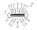
一例として、図1に図示されるように、ガスの中に浸されたペルチェ板100を以下に説明する。ペルチェ板100は、上部層101と下部層102とから構成されている。簡単にするために、デカルト座標系が、下部層102から上部層101へと指示するy軸を用いて参照される。温度差は、上部層101がガスよりも冷たく、下部層102がガスよりも熱くなるように、複数の層の間のペルチェ素子(図示せず。)もしくはいくつかの適切な手段により確立される。任意の特定の理論へと制限されたくない一方で、ペルチェ効果は、正味の熱をガスの中に移動させないように見え、ペルチェ板100により引き起こされるガスの運動量空間への変換は、エルミート行列Aにより表現される。ガス粒子(分子もしくは原子)が、下部層102と衝突する場合は、衝突が非断熱であると仮定すると、ガス粒子は衝突前よりもより高速度で跳ね返る。ガス粒子が上部層101と衝突する場合は、衝突が非断熱であると仮定すると、ガス粒子は衝突前よりもより低速度で上部層101を跳ね返る。ペルチェ板100は、下部層102から上部層101へと指示する正味の力、すなわちy方向における正味の力を感知する。言い換えると、下部層102は加熱され、それ故に下部層102より下のガスの圧力を増加させる一方で、上部層101は冷却さ
れ、それ故に上部層101より上のガスの圧力を減少させる。圧力差が、ペルチェ板100を上の方に駆動させる。ガスの運動量空間kの変換に関して、上部層101から跳ね返る複数のガス粒子は、下部層102から跳ね返る複数のガス粒子よりも低い運動量を持って離れるので、変換された運動量空間Akは、−y方向において、優先的に歪曲され、すなわち変換された運動量空間Akの期待値pはゼロ以外でかつ−y方向へ指示する。ガスとペルチェ板100とが閉じられた系(すなわち、他の複数の物体との相互作用がない。)を構成すると仮定すると、ペルチェ板100は、運動量−pを獲得して閉じられた系の全運動量を保存する。
As an example, a
図1におけるペルチェ板100の幾何学的形状がリフト(揚力)を発生する一方で、それは実際には以下の複数の理由のために使用されない。
1.もしペルチェ板100が大きいならば、ペルチェ板100のy方向に沿っての並進運動が、ガスがはるばるペルチェ板の複数のエッジの周りに流れることを強いられる。
2.熱の大部分が、ガス対流を介してペルチェ板100の複数の表面から移動される。
3.複数の表面近くのガスは、断熱効果を有する。図2に図示されるように、ペルチェ板100とガスとの間を移動された推進力(モーメント)は、板の複数のエッジの近傍を除き効率的でない。
4.ペルチェ板100の表面領域は、その凸包の表面領域である。
While the geometry of the
1. If the
2. Most of the heat is transferred from multiple surfaces of the
3. Gases near the plurality of surfaces have a heat insulating effect. As shown in FIG. 2, the propulsive force (moment) moved between the
4). The surface area of the
これらの複数の問題はすべて、ガスは任意の直接的な表面接触を全く持たないという1つの核心(コア)問題に関連している。従って、より複雑な幾何学的形状が有利になる。3つの異なる幾何学的形状を用いた例示的な複数の実施形態が、ここで以下に説明される。 All of these multiple problems are related to one core problem where the gas has no direct surface contact at all. Thus, more complex geometric shapes are advantageous. Exemplary embodiments using three different geometries are now described below.
動作の複数の原理.
NMSetもしくは関連する複数のデバイスの多くの複数の異なる幾何学的形状が可能であるが、複数のNMSetの動作原理は同一のままである。任意の特定の理論に限定されたくない一方で、動作は、いくつかの複数のデバイス表面上のエントロピーを下げ、下げられたエントロピーを表面に接触しているガスへと移動させるためにエネルギーを使用する。デバイスはオプション的に、ガス温度を上昇させることにより、ガスに対してエネルギーを提供することができる。従って、NMSetの機能は、3つの領域に分割される。すなわち、デバイスの複数の表面上エントロピーを下げる手段と、下げられたエントロピーがガスへと移動する手段と、ガス温度を増加させるオプション的な手段とである。
Multiple principles of operation.
Many different geometries of the NMSet or related devices are possible, but the operating principles of the NMSet remain the same. While not wanting to be limited to any particular theory, the operation lowers entropy on several multiple device surfaces and uses energy to move the lowered entropy to the gas in contact with the surface To do. The device can optionally provide energy to the gas by raising the gas temperature. Therefore, the function of NMSet is divided into three areas. That is, means for reducing the entropy on the plurality of surfaces of the device, means for moving the lowered entropy into the gas, and optional means for increasing the gas temperature.
温度差.
材料の複数の層間の温度差は一般的に、NMSetもしくは関連するデバイスが動作するために必要とされる。ここで説明されたより好ましい複数の実施形態において、温度差は、固体電動メカニズム、すなわちNMSetの“Se”において確立される。しかしながら、ここで説明された複数のデバイス及び複数の方法は、複数の電子固体デバイスもしくは複数の純固体デバイスに限定されない。例えば、温度差は、流体冷却、発熱化学反応、もしくは他の化学的な熱源を用いて燃焼から熱の伝導により確立されてもよい。温度差は、簡単な抵抗加熱により、ペルチェ効果により、熱トンネリングにより増強されたペルチェ効果により、もしくは任意の他の適切な手段により確立されてもよい。温度差を2つの物体の間に確立する手段は、現象学的に、2つの特性により説明される。すなわち、エントロピーの減少(2つの物体間の熱移動)、及び非断熱性(環境と2つの物体との間のトータルの熱移動)である。
Temperature difference.
Temperature differences between multiple layers of material are generally required for NMSet or related devices to operate. In the more preferred embodiments described herein, the temperature difference is established in a solid state motorized mechanism, ie “Se” of NMSet. However, the devices and methods described herein are not limited to electronic solid devices or pure solid devices. For example, the temperature difference may be established by conduction of heat from combustion using fluid cooling, exothermic chemical reactions, or other chemical heat sources. The temperature difference may be established by simple resistive heating, by the Peltier effect, by the Peltier effect enhanced by thermal tunneling, or by any other suitable means. The means of establishing a temperature difference between two objects is phenomenologically explained by two properties. Entropy reduction (heat transfer between two objects) and non-adiabatic (total heat transfer between the environment and two objects).
一実施形態において、ペルチェ効果は、温度差を確立するために使用される。ペルチェ効果は、電流が2つのジャンクションにおいて接合された、異なるペルチェ係数を有する2つの材料から構成された閉回路(ループ)により印加された場合に発生する。電流の方向によって、熱は1つのジャンクションから他のジャンクションへと流れ、温度差を複数のジャンクション間に確立させる。ペルチェ効果は、以下のように理解される。すなわち、材料における複数の電荷キャリアの熱容量は、材料における複数の電荷キャリアあたりに運ばれた熱の量であるペルチェ係数Пにより特徴付けられる。電流Iは、ペルチェ係数ПAを有する材料Aとペルチェ係数ПBを有する材料Bとのジャンクションを通り抜けて流れる場合に、単位時間における、複数の電荷キャリアによりジャンクションへと運ばれる熱量は、I×(ПA−ПB)である。 In one embodiment, the Peltier effect is used to establish a temperature difference. The Peltier effect occurs when current is applied by a closed circuit (loop) composed of two materials with different Peltier coefficients joined at two junctions. Depending on the direction of the current, heat flows from one junction to the other, establishing a temperature difference between the junctions. The Peltier effect is understood as follows. That is, the heat capacity of the plurality of charge carriers in the material is characterized by the Peltier coefficient П, which is the amount of heat carried per plurality of charge carriers in the material. When the current I flows through a junction between a material A having a Peltier coefficient П A and a material B having a Peltier coefficient П B , the amount of heat carried to the junction by a plurality of charge carriers per unit time is I × (П A −П B ).
ペルチェ効果は、局所的にエントロピーを減少させ、断熱効果である。ジュール熱を無視すると仮定すると、ペルチェ効果において、熱が1つのジャンクションから他のジャンクションへと移動されるが、熱は2つの材料のループの中には追加されない。このエントロピーの減少は、NMSet及び関連する複数のデバイスの積層可能性(スタッカビリティ)における複数の利点を提供することができる。結果的に、ペルチェ効果は、特に十分にいくつかの複数の実施形態に役に立つ。 The Peltier effect is an adiabatic effect that locally reduces entropy. Assuming that Joule heat is ignored, in the Peltier effect, heat is transferred from one junction to another, but no heat is added into the loop of two materials. This reduction in entropy can provide multiple benefits in the stackability of NMSet and related devices. As a result, the Peltier effect is particularly useful for some embodiments.
この実施形態において、電源は2つの表面間の電流を駆動させる。例えば、複数の電子及び/または複数のホール(正孔)などの複数の電荷キャリアは、それらが電流に流れるので熱を運び、それ故に2つの表面間の温度差を創造する。温度差が確立されるのでエントロピーは減少する。 In this embodiment, the power supply drives a current between the two surfaces. For example, a plurality of charge carriers, such as a plurality of electrons and / or a plurality of holes (holes), carry heat as they flow into the current, thus creating a temperature difference between the two surfaces. As the temperature difference is established, the entropy decreases.
フォノンのフロー(流れ)は、ペルチェ効果により確立された温度差により減少する。もし複数のフォノンが、自由に流れることができるならば(すなわち、無限の熱伝導性もしくはゼロ熱容量)、それらのフローは、温度差により確立されたペルチェ効果を相殺するであろう。ペルチェ効果の効率性は、電気抵抗及び熱伝導率を減少させることにより増加される。 The phonon flow is reduced by the temperature difference established by the Peltier effect. If multiple phonons can flow freely (ie, infinite thermal conductivity or zero heat capacity), their flow will offset the Peltier effect established by the temperature difference. The efficiency of the Peltier effect is increased by reducing electrical resistance and thermal conductivity.
熱伝導率を減少させるための1つの方法は、電流のパスにおいて狭い真空ギャップを配置することである。複数のフォノンは容易に、真空ギャップを通過することができないが、複数の電荷キャリアは真空ギャップ間のある電圧の条件のもとで通過することができる。このことは、熱トンネリングにより増強されたペルチェ効果(もしくは熱トンネル冷却)と呼ばれる。図6は、熱トンネリングにより増強されたペルチェ効果を図示する。複数の電荷キャリア601は、真空ギャップ602を通り抜けることができる。
One way to reduce thermal conductivity is to place a narrow vacuum gap in the current path. Multiple phonons cannot easily pass through the vacuum gap, but multiple charge carriers can pass under certain voltage conditions across the vacuum gap. This is called the Peltier effect (or thermal tunnel cooling) enhanced by thermal tunneling. FIG. 6 illustrates the Peltier effect enhanced by thermal tunneling. A plurality of
もし真空ギャップ近くの複数の電荷キャリアの挙動を制限し、トンネリング可能性を増加させることができる表面幾何学的形状及び複数の材料の選択によりペルチェ効果が増強されないならば、熱トンネリングにより増強されたペルチェ効果は一般的に、複数の高い温度もしくは複数の高い電圧においてだけに重要となる。例えば、適切な複数の表面コーティング及び複数の構造は、複数の電荷キャリアの複数の低エネルギー状態ではなく、真空ギャップ近くの複数の電荷キャリアの高エネルギー状態だけを可能とさせるフィルターとして機能することができる。 If the Peltier effect is not enhanced by the choice of surface geometry and multiple materials that can limit the behavior of multiple charge carriers near the vacuum gap and increase the tunneling potential, enhanced by thermal tunneling The Peltier effect is generally only important at multiple high temperatures or multiple high voltages. For example, suitable surface coatings and structures can function as a filter that allows only high energy states of multiple charge carriers near the vacuum gap, not multiple low energy states of multiple charge carriers. it can.
もう1つの実施形態において、温度差は、電界により増強された熱イオン放出により創造されて維持される。熱イオン放出は、ポテンシャルエネルギー障壁を越えた複数の電荷キャリアの熱誘導されたフローである。複数の電荷キャリアは、複数の電子もしくは複数のイオン(すなわち、複数の熱イオン)である。簡単な近似において、ポテンシャルエネルギー障壁は、それがその高さよりも小さい熱エネルギーを有する複数のキャリアを引き留めて、その高さよりも高い熱エネルギーを有する複数のキャリアが超えて流れることを可能とするという点において、ダムのように動作する。超えて流れてくる複数のキャリアがポテンシャルエネルギー障壁を通過するとき、それらと一緒に熱が運び去られる。ポテンシャルエネルギー障壁の後ろに残された複数のキャリアは、より低温度へ再熱運動化(エネルギーにおける再分配)される。熱イオン放出は典型的に、無視できないごく少量のキャリアがポテンシャルエネルギー障壁に打ち勝つのに十分に大きい複数の熱エネルギーを持つことができるように、数百度摂氏の動作温度を必要とする。電界は、ポテンシャルエネルギー障壁の高さを減少させて必要とされる動作温度を減少させることにより、熱イオン放出をアシストする(助ける)ことができる。 In another embodiment, the temperature difference is created and maintained by thermionic emission enhanced by the electric field. Thermionic emission is a thermally induced flow of multiple charge carriers across the potential energy barrier. The plurality of charge carriers are a plurality of electrons or a plurality of ions (that is, a plurality of thermal ions). In a simple approximation, the potential energy barrier says that it retains multiple carriers with thermal energy less than its height, allowing multiple carriers with thermal energy higher than its height to flow past. In point, it behaves like a dam. When multiple carriers flowing past the potential energy barrier, heat is carried away with them. The multiple carriers left behind the potential energy barrier are reheated (redistribution in energy) to a lower temperature. Thermal ion emission typically requires operating temperatures of several hundred degrees Celsius so that a negligible number of carriers can have multiple thermal energies large enough to overcome the potential energy barrier. The electric field can assist (help) thermionic emission by reducing the height of the potential energy barrier to reduce the required operating temperature.
NMSetもしくは関連するデバイスにおける温度差はまた、抵抗加熱を用いることにより、及び/または適切な複数の化学処理により確立される。デバイスの全体温度を上昇させることなしに、温度差を維持するために、例えば大気にさらされる放熱板などのいくつかの冷却手段がまた提供される。いかなる冷却手段が用いられたとしても、もしデバイスのより温かい複数の表面が、より冷たい複数の表面と同じように効率的に冷却されないならば、温度差はより顕著となり、例えば断熱により、それが実現される。 Temperature differences in NMSet or related devices are also established by using resistive heating and / or by appropriate multiple chemical treatments. In order to maintain the temperature difference without increasing the overall temperature of the device, several cooling means are also provided, such as a heat sink exposed to the atmosphere. Whatever means of cooling is used, if the warmer surfaces of the device are not cooled as efficiently as the cooler surfaces, the temperature difference becomes more pronounced, e.g. by thermal insulation, Realized.
応力の生成.
ある態様において、正味の推進力の生成は、確立された温度差からの減少されたエントロピーのガスへの移動として考えられる。理論により縛られたくないのであれば、ガスにおいて動作する1つのデバイスが断熱処理される実施例について以下に説明する。この実施例において、加熱層と冷却層との間の温度差が、ペルチェ効果などの適切な手段により確立される。簡単にするために、正味の熱がガスとデバイスとの間を移動しないと仮定すると、ガスの複数の粒子は、複数の等しい確率で、加熱層と冷却層とに衝突するであろうし、それらのこれらの複数の層との相互作用は、加熱層と冷却層の複数の表面近くのガスの局所的な運動量空間上に複数の結果を有するであろう。加熱層と冷却層の表面に非常に接近しているガスの局所的な運動量空間は、ガスと表面とが異なる複数の温度を有する場合は、ゼロ以外の期待値を有する。また、複数のガス粒子がまったく表面を突き抜けないと仮定すると、複数のガス粒子は、それらの複数の入斜運動量と異なる複数の運動量を持って表面から跳ね返り、それが表面法線に沿って運動量空間を歪曲させ、当該歪曲の大きさは直接的に、表面とガスとの間の温度差に関連する。
Stress generation.
In certain embodiments, the generation of net propulsion is considered as a transfer of reduced entropy to the gas from the established temperature difference. If one does not wish to be bound by theory, an embodiment is described below in which one device operating in gas is adiabatic. In this embodiment, the temperature difference between the heating layer and the cooling layer is established by suitable means such as the Peltier effect. For simplicity, assuming that no net heat moves between the gas and the device, multiple particles of gas will collide with the heating and cooling layers with multiple equal probabilities and they Interaction with these multiple layers will have multiple consequences on the local momentum space of the gas near the multiple surfaces of the heating and cooling layers. The local momentum space of the gas that is very close to the surfaces of the heating and cooling layers has an expected value other than zero if the gas and the surface have different temperatures. Also, assuming that multiple gas particles do not penetrate the surface at all, the multiple gas particles bounce off the surface with multiple momentums different from their multiple oblique momentum, which is momentum along the surface normal. The space is distorted and the magnitude of the distortion is directly related to the temperature difference between the surface and the gas.
ランダムな幾何学的形状を用いた配列において(すなわち、異なる複数の表面場所での複数の表面法線はランダムな複数の方向へ指示する。)、ガスの局所的な複数の運動量空間の複数の期待値の加重和はほとんどゼロであり、それが結果として正味の推進力をほとんど生じさせない。最適化された幾何学的形状を有するNMSetにおいては、しかしながら、ガスの局所的な複数の運動量空間の複数の期待値の加重和はゼロ以外となることができ、それが正味の推進力へと導く。 In an array using random geometry (ie, multiple surface normals at different surface locations point in multiple random directions), multiple local momentum spaces of the gas The weighted sum of expected values is almost zero, which results in little net driving force. In an NMSet with an optimized geometry, however, the weighted sum of the expected values of the local momentum spaces of the gas can be non-zero, which leads to a net driving force. Lead.
ゼロ以外の正味の推進力を有する配列の些細な実施例が、上述されたように、図1に図示される。この幾何学的形状は、巨視的な複数の対流ガスフロー及び渦変形がエントロピーを増加させて役立つ作業量を制限するので、全く効率的でない。例示的な対流ガスフロー120、130が図2に図示される。周囲温度におけるガス110は、冷却層101の方向に流れて冷却される。冷却されたガス120は、冷却層101から離れて加熱層102に向かってペルチェ板100のエッジの周りを流れる。複数の加熱されたガス130は、加熱層102から離れて流れる。
A trivial example of an arrangement with a net driving force other than zero is illustrated in FIG. 1 as described above. This geometry is not quite efficient because the macroscopic convective gas flows and vortex deformations increase entropy and limit the amount of work that can be useful. An exemplary
説明を簡単にするために、ニュートンの第2法則及び気体運動論に従った系について考えることが役に立つかもしれない。図1及び図2におけるペルチェ板100の周辺で、ガスの温度を層101及び102の温度によりひとくくりにすると仮定すると、層101と衝突する複数のガス粒子は、衝突前よりもより大きな運動量を持って層101から離れる。同様に、層102と衝突する複数のガス粒子は、衝突前よりもより小さい運動量を持って層102から離れる。ガス圧は、複数のガス粒子の複数の運動量に直接的に関連するので、層102近くのガスは、層101近くのガスよりもより高い圧力を有する。この圧力バイアスは、y方向に全体の板100を押す。
To simplify the explanation, it may be useful to consider systems that follow Newton's second law and gas kinetics. Assuming that the temperature of the gas is gathered around the
もう1つの実施形態において、ペルチェ板100は、層101と層102との間に少なくとも1つのスルーホールを持つことができる。ガスは自発的に、より高いガスの加熱レートを可能とさせるスルーホールを通り抜けて層101から層102へと流れる。そのようなガスのフローは、熱発散と呼ばれる。層101近くのガスがTcの温度及びPcの圧力を有し、層102近くのガスがThの温度及びPhの圧力を有すると仮定し、もし以下の等式が満たされるならば、熱発散により、ガスがスルーホールを通り抜けて層101から層102へと流れる。
In another embodiment, the

効率性を改善するために、古典的な制限が複数のガスフロー内に存在する場合を理解することは役に立つ。ガスフローの対流の説明は、クヌーセン数がゼロになる複数の長さスケールの周辺で行き詰まる。結果として、いくつかの複数の態様において、ガスの平均自由行程は、NMSetの有利な複数の幾何学的形状を決定するときにおける、役に立つパラメータとなる。 In order to improve efficiency, it is helpful to understand when classical limitations exist in multiple gas flows. The description of gas flow convection is stuck around multiple length scales where the Knudsen number is zero. As a result, in some embodiments, the mean free path of the gas is a useful parameter in determining the advantageous NMSet geometries.
例えば、10nmの平均自由行程を有する特定の圧力でのガスについて以下に説明する。もしそのようなガスの大群が、図3に図示された1辺が20nmの2次元の正方形の箱の中に閉じ込められたならば、10nmの移動範囲内のガス粒子は近似的に、それが箱の複数の壁とぶつかった可能性があるのと同じように、もう1つのガス粒子にぶつかった可能性があろう。もし箱の複数の壁が加熱されるならば、より小さい複数の箱の中の複数のガス粒子は複数の壁と衝突して当該複数の壁と熱交換するためのより多くの複数の機会を持つので、次により小さい複数の箱がより大きい複数の箱よりも速いそれらの中のガスと熱力学的平衡に達するであろう。一般的に、ガスにおける複数の衝突のほとんどが、複数のガス粒子と表面との間である場合は、次に熱力学的平衡は平均自由時間(ガス粒子が平均自由行程を移動する時間)内に近似的に達成される。 For example, a gas at a specific pressure having a mean free path of 10 nm is described below . If such a large group of gases is confined in a two-dimensional square box with one side illustrated in FIG. 3 of 20 nm, a gas particle within a 10 nm moving range is approximately You may have hit another gas particle just as you might have hit the walls of the box. If multiple walls of a box are heated, multiple gas particles in smaller multiple boxes will collide with multiple walls and provide more multiple opportunities for heat exchange with the multiple walls. Having so, the next smaller boxes will reach a thermodynamic equilibrium with the gas in them faster than the larger boxes. In general, if most of the multiple collisions in the gas are between multiple gas particles and the surface, then the thermodynamic equilibrium is within the mean free time (the time during which the gas particles travel the mean free path ) Is approximately achieved.
この理由のために、いくつかの複数の実施形態において、NMSet及び関連する複数のデバイスの個々の複数の特徴の特性スケールはナノスケール、すなわちNMSetの“NM”であってもよい。しかしながら、ここで説明された複数の方法及び複数のデバイスはナノスケールの複数の実施形態には限定されないことを理解しなければならない。平均自由行程パラメータは、いくつかの複数の実施形態と複数の使用において、より大きいスケールの複数の特徴が利用されてもよいように、ガス密度に依存している。さらに、ここで説明されるように、複数のNMSet及び関連するデバイス要素は、大きい表面にわたる行動を提供するために組み合わされる。例えば、NMSetもしくは関連する複数のデバイスは、例えば図16及び図17に図示されるように、大きい複数の表面間にわたってガスの方向づけられた移動を提供するために複数のアレイ及び複数のアレイの複数のアレイにおいて有利に配列されてもよい。NMSetもしくは関連する複数のデバイス要素はまた、例えば図18A−図18Dに図示されるように、より大きい圧力差を達成するために1つもしくはそれ以上のステージにおいて配列される。図18Aは、ステージ型NMSetもしくは関連する複数のデバイスの複数の配列1800のアレイの断面図を図示する。各ステージ型配列1800は、図18B−図18Dにおいて拡大図示されたNMSetもしくは関連する複数のデバイス1840、1850、1860の複数のアレイを含む同心半球状のステージ1810、1820、1830から構成される。各ステージにおける個々のNMSetの開口1845、1855、1865は、動作中に各後段において経験するであろう周囲の圧力の減少に従って、サイズが大きくなる。
For this reason, in some embodiments, the characteristic scale of individual features of NMSet and related devices may be nanoscale, or “NM” of NMSet. However, it should be understood that the methods and devices described herein are not limited to nanoscale embodiments. The mean free path parameter is dependent on gas density so that features of larger scale may be utilized in some embodiments and uses. Further, as described herein, multiple NMSets and associated device elements are combined to provide behavior over a large surface. For example, the NMSet or related devices may include multiple arrays and multiple arrays to provide directed movement of gas across multiple large surfaces, eg, as illustrated in FIGS. May be advantageously arranged in an array of The NMSet or associated device elements are also arranged in one or more stages to achieve a larger pressure differential, as illustrated, for example, in FIGS. 18A-18D. FIG. 18A illustrates a cross-sectional view of an array of
表面相互作用.
複数の表面間の相互作用が、運動量空間変換行列Aに影響を与えることができる。もしすぐ近くの複数の表面が容易に、複数のガス粒子を介して複数のフォノンを交換できるならば、次にこれらの複数の表面におけるエントロピーが、複数の渦の発展を介して複数のフォノンを容易に交換することができない複数の表面よりも、より高レートで局所的に増加されるであろう。これが一般的に、システムの効率性を減少させるであろう。
Surface interaction.
Interactions between multiple surfaces can affect the momentum space transformation matrix A. If multiple nearby surfaces can easily exchange multiple phonons through multiple gas particles, then the entropy at these multiple surfaces will convert multiple phonons through multiple vortex evolution. It will be increased locally at a higher rate than multiple surfaces that cannot be easily replaced. This will generally reduce the efficiency of the system.
フォノン交換が減少される1つの方法は、複数の表面間の任意の複数の共有のベース(基礎)を制限もしくは削除することである。例えば、図3の箱300の中の複数のガス粒子について考える。箱300は、相互に平行する2つの平面の加熱壁302と、相互に平行する2つの平面の冷却壁301とから構成される。もし箱300がその中の複数のガス粒子の平均自由行程とサイズにおいて同等であり、複数の壁301及び302が完全に正反射性であるならば、複数のガス粒子は、複数の冷却壁301と複数の加熱壁302と独立して熱平衡に達することができる。これは、複数の壁の複数の表面法線が、2つの冷却壁301の間だけで、もしくは2つの加熱壁302の間だけで共有されているが、冷却壁301と加熱壁302との間では共有されていないからである。結果的に、運動量は、複数のガス粒子により、複数の加熱壁302と複数の冷却壁301との間で交換されない。これは、複数の粒子と複数の冷却壁301との間の相互作用は、x方向における複数の運動量だけに影響を与え、y方向における複数の運動量に影響を与えないからである。すなわち、複数のガス粒子と複数の加熱壁302との間の相互作用は、y方向における複数の運動量だけに影響を与えるが、x方向における複数の運動量及びx方向における複数の運動量がy方向における複数の運動量と直交するという事実には影響を与えない。熱平衡が、複数のガス粒子と複数の壁との間で達せられた後、複数のガス粒子は、y方向においてよりもx方向において、より速く移動する。
One way in which phonon exchange is reduced is to limit or eliminate any shared base between multiple surfaces. For example, consider a plurality of gas particles in the
実用的な問題として、複数の表面は通常、完全に正反射性でない。しかしながら、正反射性の複数の表面特性は、複数のコーナ(角)において複数の対流フローが減少される複数の角度が存在できるように、いくつかの複数の材料において非常に強く存在する。この効果は一般的に、複数のクヌーセン数が大きい場合に観察され、これが、特にナノスケールの複数の実施形態におけるNMSet及び関連する複数のデバイスのためのより好ましい条件である。デンマーク人の物理学者のマルチンクヌーセン(1871−1949)により名付けられたクヌーセン数(Kn)は、分子の平均自由行程の代表的な物理学の長さスケールに対する比として定義された無次元数である。ここで説明されたNMSetもしくは関連する複数のデバイスにおいて、代表的な物理学の長さスケールは、デバイスの開口直径の大きさの次数に対して取られる、すなわち代表的な物理学のスケール長さは、もし開口が複数のナノメータにおいて測定されたならばナノメータであり、もし開口が複数のマイクロメータにおいて測定されたならばマイクロメータである。ここで開示された複数のデバイスを使用するより好ましい複数の方法において、クヌーセン数は好ましくは0.1よりも大きく、もしくは1よりも大きく、もしくは10よりも大きい。 As a practical matter, multiple surfaces are usually not fully specular. However, specular multiple surface properties exist very strongly in several materials so that there can be multiple angles at which multiple convective flows are reduced at multiple corners. This effect is generally observed when multiple Knudsen numbers are large, which is a more favorable condition for NMSet and related devices, especially in nanoscale embodiments. The Knudsen number (Kn), named by Danish physicist Martin Knudsen (1871-1949), is a dimensionless number defined as the ratio of the mean free path of a molecule to the typical physics length scale. . In the NMSet or related devices described herein, a typical physics length scale is taken for the order of magnitude of the device's aperture diameter, ie, a typical physics scale length. Is nanometer if the aperture is measured in multiple nanometers and micrometer if the aperture is measured in multiple micrometers. In more preferred methods of using the devices disclosed herein, the Knudsen number is preferably greater than 0.1, or greater than 1, or greater than 10.
NMSet及び関連する複数のデバイスの最適化方法.
モデリング.
特定の幾何学的形状を有するNMSetのパフォーマンスは、最適化のためのモンテカルロ法によりシミュレーションされる。特に、任意の所定の幾何学的形状を有するNMSetもしくは関連するデバイスのためのシミュレーションは、ランダムな最初の複数の位置及びデバイスの周りの複数の運動量を有する複数のガス粒子のグルーピングから開始される。短い時間の間隔の後のこれらの複数の粒子の複数の位置及び複数の運動量は、知られている複数の物理学法則、例えば温度や圧力などの複数のパラメータ、化学的同一性、デバイスの幾何学的形状、デバイスの複数の表面間の相互作用、及び複数の粒子を用いて、最初の複数の位置及び複数の運動量から計算される。シミュレーションは、選択された数の反復により実行され、複数のシミュレーションの結果が分析される。デバイスの幾何学的形状は、上記複数のシミュレーション結果を用いて最適化される。より好ましい複数の実施形態において、デバイスは、複数のシミュレーション分析の複数の結果を用いて構成される。
A method for optimizing NMSet and related devices.
modeling.
The performance of NMSet with a specific geometric shape is simulated by Monte Carlo method for optimization. In particular, a simulation for an NMSet or related device having any given geometric shape starts with a grouping of gas particles having a random initial multiple positions and multiple momentums around the device. . The position and momentum of these particles after a short time interval are the known physics laws, such as parameters such as temperature and pressure, chemical identity, device geometry, etc. Using the geometric shape, the interaction between the multiple surfaces of the device, and the multiple particles, it is calculated from the initial multiple positions and multiple momentums. The simulation is performed with a selected number of iterations and the results of multiple simulations are analyzed. The device geometry is optimized using the simulation results. In more preferred embodiments, the device is configured with multiple results of multiple simulation analyses.
より好ましい実施形態において、シミュレーションは次表において表される。
――――――――――――――――――――――――――――――――――――――
アルゴリズム 1 EVOLVE MODEL(M,P,k)
――――――――――――――――――――――――――――――――――――――
M←0
P←a set of search parameters
k←number of iterations
for i=1 to k do
V←An instance of P
V←V perturbed by M
E←MONTE CARLO(V)
Update M using E
end for
――――――――――――――――――――――――――――――――――――――
In a more preferred embodiment, the simulation is represented in the following table.
――――――――――――――――――――――――――――――――――――――
――――――――――――――――――――――――――――――――――――――
M ← 0
P ← a set of search parameters
k ← number of iterations
for i = 1 to k do
V ← An instance of P
V ← V perturbed by M
E ← MONTE CARLO (V)
Update M using E
end for
――――――――――――――――――――――――――――――――――――――
摂動モデルMが、反復数(k)により展開される。先ず最初に、解知識を示さない空のセットに初期化される。次に、複数の検索パラメータが画成された検索空間Pから任意の要素を生成するループが開始され、前に学習されたナレッジMがPを摂動するために使用される。特定のアルゴリズムが詳細な実施例として摂動するために使用される。 A perturbation model M is developed with the number of iterations (k). First, it is initialized to an empty set that does not show solution knowledge. Next, a loop is generated that generates an arbitrary element from the search space P in which a plurality of search parameters are defined, and the previously learned knowledge M is used to perturb P. A specific algorithm is used to perturb as a detailed example.
グリッドコンピューティング環境において実行されるならば、Mは理想的には、すべての複数のノードの間で同一であるべきであるが、これは本質的に処理の確率的性質のために必ずしも必要ではない。実際はモンテカルロシミュレーションを実行するEVOLVE_MODELのステップは、すべての中においてはるかに最もコンピュータ的に高価であり、Mを同期化させるための多くの時間を提供する。 If implemented in a grid computing environment, M should ideally be the same among all multiple nodes, but this is not necessarily necessary due to the probabilistic nature of processing. Absent. In fact, the EVOLVE_MODEL step of performing a Monte Carlo simulation is by far the most computationally expensive of all and provides a lot of time to synchronize M.
特定の複数のパラメータは、環境に依存する。ユーザが特定化できる複数のパラメータは、以下を含む。
1.例えば二酸化炭素もしくは水などの3つの原子までを含むいくつかの複数の実施例における、複数の分子図(ダイアグラム)。
2.複数の構成分子に対する部分的な濃度。
3.全体のガスの初期温度及び初期圧力。
The specific parameters depend on the environment. The plurality of parameters that can be specified by the user includes:
1. Multiple molecular diagrams in several embodiments, including up to three atoms, such as carbon dioxide or water.
2. Partial concentration for multiple constituent molecules.
3. The initial temperature and initial pressure of the entire gas.
静止したシミュレーションにおいて、モンテカルロシミュレーションはすべての複数の軸における周期的な複数の境界を用いて実行される。y軸において、しかしながら、周期的な境界に出くわす複数の粒子は、複数の周囲条件をシミュレーションするために、温度及び圧力の複数のセッティングに従って、確率的に温度自動調整化される。x軸において、複数の粒子速度は、その方向に沿った同一のデバイスの複数のアセンブリの周期的なアンサンブル(集合体)をシミュレーションするために、変形されない。シミュレーションは、シミュレーションのコンピュータ的な複雑性を減少させるために、2次元において実行されてもよい。3次元シミュレーションは、モデル化されたデバイスが円筒対称性を有する場合と同様の複数の結果を与えるべきである。留意すべきことは、一般的に、シミュレータはここで示された周期性を使用する必要がなく、任意の複数の境界をまったく特定化しなくてもよい、ということである。すなわち、それらは、コンピュータ的な利便性としてだけに定義される。 In stationary simulations, Monte Carlo simulations are performed with periodic boundaries on all axes. In the y-axis, however, particles that encounter periodic boundaries are stochastically self-adjusted according to multiple settings of temperature and pressure to simulate multiple ambient conditions. In the x-axis, multiple particle velocities are not deformed to simulate periodic ensembles of multiple assemblies of the same device along that direction. The simulation may be performed in two dimensions to reduce the computational complexity of the simulation. The 3D simulation should give multiple results similar to the case where the modeled device has cylindrical symmetry. It should be noted that, in general, the simulator does not need to use the periodicity shown here and may not specify any multiple boundaries at all. That is, they are defined only as computer convenience.
より好ましい複数の実施形態において、潜在的な複数のデバイス幾何学的形状は、当該デバイスが使用されるであろう複数の条件及び、それが構成されるであろう材料の知られた複数の表面反射特性を考慮して計算される。幾何学的な複数のパラメータは、幾何学的形状がNMSet及び関連する複数のデバイスの製造において実際に使用される前にシミュレーションからの複数の結果を分析することにより最適化される。 In more preferred embodiments, the potential device geometries are the conditions under which the device will be used and the known surfaces of the material from which it will be constructed. Calculated taking into account reflection characteristics. The geometric parameters are optimized by analyzing the results from the simulation before the geometry is actually used in the manufacture of the NMSet and associated devices.
幾何学的形状の実施例.
異なる複数の幾何学的形状を有する4つの実施形態が、特に以下に論じられる。これらの4つの幾何学的形状を、一直線形状、放物線形状、三角形形状、及びのこぎり歯形状、と呼ぶ。ここで説明されたNMSet及び関連する複数のデバイスの複数の幾何学的形状はかなり変えることができ、これらの複数の実施例は、ある設計の複数の選択の系の複数の係数への複数の影響を論じるための複数の図としてだけに解釈される、ということに留意されるべきである。
Examples of geometric shapes.
Four embodiments with different geometric shapes are discussed in particular below. These four geometric shapes are referred to as a straight line shape, a parabolic shape, a triangular shape, and a sawtooth shape. The geometric shapes of the NMSet and related devices described herein can vary considerably, and these examples can be used to provide multiple coefficients to multiple coefficients for multiple designs of a design. It should be noted that it is interpreted only as multiple figures to discuss the impact.
一直線形状.
図19は、一直線形状を有するNMSetもしくは関連するデバイス1900の実施形態を図示する。この実施形態において、デバイス1900は、加熱層1902及び冷却層1901から構成される。用語“加熱層”と用語“冷却層”は、これらの複数の層がそれらの間に温度差を持つことを意味し、NMSetもしくは関連するデバイスが浸されたガスよりも、“加熱層”が必ずしも熱くなく、または“冷却層”が必ずしも冷たくない、ということを意味する。少なくとも1つの一直線のスルーホール1910が、デバイス1900のすべての複数の層を通り抜けて延長し、好ましくは各層上に同一の断面形状及びサイズを有する。一直線のスルーホール1910は、例えば円の、スリット、及びくし状などの任意の断面形状を持つことができる。
Straight line shape.
FIG. 19 illustrates an embodiment of a NMSet or
好ましくは、一直線のスルーホール1910の全体の長さ1910L(すなわち、一方の入り口から他方の入り口までの距離)は、デバイス1900が浸されたガスの平均自由行程の10倍まで、5倍まで、もしくは2倍までである。標準の大気圧における空気の平均自由行程は、約55nmである。より高度では、空気の平均自由行程は増加する。大気の複数の応用のために、全体の長さ1910Lは好ましくは、1500nmより大きくない。加熱層1902と冷却層1901との間の温度差は好ましくは、少なくとも30度であり、より好ましくは少なくとも50度であり、最も好ましくは少なくとも100度である。
Preferably, the
加熱層1902及び冷却層1901は、熱分離のために、それらの間のギャップにより分離されてもよい。当該ギャップは好ましくは、真空ギャップ及び/または熱絶縁体を含む。ある複数の実施例において、ギャップは、例えば二酸化シリコンなどの十分な熱絶縁体から作られた複数の薄い支柱(ピラー)を含む。
The
デバイス1900は好ましくは、平方センチメータあたり少なくとも10個の一直線のスルーホールを有する。平方センチメータあたりのデバイスのすべての複数の一直線のスルーホールの全体の周囲の長さは好ましくは、少なくとも2センチメータである。
放物線形状.
図7は、放物線形状を有するNMSetもしくは関連するデバイス700を図示する。この実施形態において、代わりの複数の加熱層702及び複数の冷却層701が積層される。図において、各加熱層702及び冷却層701は、一直線のスルーホールを有する。すべての複数の穴が位置合わせされる。各加熱層702における穴は、すぐ上の冷却層701における穴と同じサイズを有し、すぐ下の冷却層701における穴よりも小さい。各冷却層701は、そのすぐ隣接した複数の加熱層702よりも冷たく、各加熱層702はそのすぐ隣接した複数の冷却層701よりも熱い。−y方向において表面法線を有する各加熱層702の表面702aが露出される。すべての複数の穴は集合的に、放物線表面の輪郭を有するノズルを形成する。この幾何学的形状は、複数の加熱層と複数の冷却層との間の共有の複数のベースを最小化させる。しかしながら、NMSetもしくは関連するデバイスは必ずしもガスのエネルギーを増加させないので、穴の直径を増加させることは、結果としてガス圧における降下を生じさせる。これが、下部の開口近くの強い複数の渦を創造することができ、これが全体の効率性を低下させる。放物線形状を有するNMSetは、断熱のもしくは定圧とすることができるが、これらの両方はできない。放物線形状を有するNMSetもしくは関連するデバイスにおけるガスフローの近似が、図8に図示される。ガスの運動量空間は、運動量の期待値が−y方向へ指示することできるように、歪曲される。
Parabolic shape.
FIG. 7 illustrates a NMSet or
NMSetもしくは関連するデバイスにおいて放物線形状が効果的であるのだが、ガス圧における降下は、より高い境界をより低い開口のサイズ上に寄与する。一般的に、移動されたガスが体積における変化を経験する任意の断熱デバイスは、その効率性において苦しむであろう。 Although parabolic shapes are effective in NMSet or related devices, the drop in gas pressure contributes higher boundaries to lower aperture sizes. In general, any insulation device in which the transferred gas experiences a change in volume will suffer in its efficiency.
もし放物線形状を有するデバイスにおける温度差が非断熱手段(すなわち、デバイスがガスの全体温度を上昇させる。)により確立されるならば、次に放物線形状を有するNMSetは、ガスに追加された熱量が複数の渦の形成を回避するのに十分である限り、その効率性において、体積において変化を経験するガスに苦しまなくてもよい。しかしながら、そのようなデバイスは、その効率性において、より高い全体エントロピーを受け、すなわち、もしガスが膨張されなければならないならば、ガスの運動量空間の複数の固有ベクトルが遠く離れていないが、小さい複数のスケールにおいて熱を供給することは典型的には、それを運び去ることよりも容易である。 If the temperature difference in a device having a parabolic shape is established by non-adiabatic means (ie, the device raises the overall temperature of the gas), then the NMSet having a parabolic shape will cause the amount of heat added to the gas to be As long as it is sufficient to avoid the formation of multiple vortices, its efficiency does not have to suffer from a gas that experiences a change in volume. However, such devices are subject to higher overall entropy in their efficiency, i.e., if the gas has to be expanded, the eigenvectors of the gas momentum space are not far apart, but small It is typically easier to supply heat on the scale than to carry it away.
三角形形状.
図9に詳細図示された三角形形状は、複数の断熱フローのための放物線形状の部分的な最適化である。このケースにおいて、ガスは大きいスケールの渦生成をトリガーさせるための十分な膨張を経験することが不可能とされる。さらに、複数の開口はサイズを変化させないので、このような三角形配列は、容易に積層されてもよい。
Triangular shape.
The triangular shape illustrated in detail in FIG. 9 is a partial optimization of the parabolic shape for multiple adiabatic flows. In this case, the gas is deemed unable to experience sufficient expansion to trigger large scale vortex generation. Furthermore, since the plurality of openings do not change size, such a triangular array may be easily stacked.
図10に図示されるように、この三角形形状の運動量空間はより効率的にバイアスされる。放物線配列におけるように、露出された複数の加熱表面及び複数の冷却表面は、90度の角度で合わされ、しかしながら、複数の粒子は、熱を、中心のギャップ間の複数の表面間を前後して運ぶ場合は、非効率性のソース(源)が生じる。 As illustrated in FIG. 10, this triangular shaped momentum space is biased more efficiently. As in the parabolic arrangement, the exposed heating surfaces and cooling surfaces are combined at a 90 degree angle, however, the particles can transfer heat back and forth between the surfaces between the central gaps. When carrying, inefficient sources arise.
図9は、三角形形状を有するNMSetもしくは関連するデバイスの積層900を図示する。積層900における各デバイスは、等しい厚さの加熱層902と冷却層901とから構成されている。冷却層901と加熱層902との間の温度差は、ペルチェ効果などの任意の適切な手段により確立される。各デバイスは、スルーホール903を有する。各スルーホール903は各入り口に45度の面(9031及び9032)を有する。面9031及び面9032の幅は、複数の冷却層901及び複数の加熱層902の厚さの1.40倍から1.42倍である。積層900におけるすべての複数の層における複数のスルーホール903は位置合わせされる。一般的に、積層900における複数の加熱層902の複数の温度は、積層の一方側から他方側へと単調に増加しない。一般的に、積層900におけるデバイスにおける複数の加熱層902の複数の温度は、積層の一方側から他方側へと単調に減少しない。好ましくは、各冷却層901は、そのすぐ隣接した複数の加熱層902よりも冷たく、各加熱層902は、そのすぐ隣接した複数の冷却層901よりも熱い。
FIG. 9 illustrates a
のこぎり歯形状.
図11は、のこぎり歯形状を有するNMSetもしくは関連するデバイスの積層1100を図示する。積層1100における各デバイスは、thの厚さを有する加熱層1102と厚さtcを有する冷却層1101とから構成されている。複数の冷却層1101と複数の加熱層1102との間の温度差は、例えばペルチェ効果などの任意の適切な手段により確立される。各デバイスは、スルーホール1103を有する。図示されたデバイスにおいて、各スルーホール1103は冷却層1101側の入り口において面11031を有し、加熱層1102側の入り口における面11032を有する。面11031とスルーホール1103の中心軸との間の角度はθ1であり、面11032とスルーホール1103の中心軸との間の角度はθ2である。θ1とθ2との合計は好ましくは、85度から95度であり、より好ましくは88度から92度である。tcのthに対する比は実質的に、θ1の余接のθ2の余接に対する比に等しい。θ2は好ましくは、70度から85度である。
Sawtooth shape.
FIG. 11 illustrates a
ここで説明された面の複数の角度の複数の関係は、望ましい複数の制限であって、ハードな(硬い)複数の境界ではない。ここで、「望ましい複数の制限」とは、例えば個々に選択できる制限などの個々の好みで選択される制限のことであり、「ハードな複数の境界」とは、確固たる/明確な境界のことであり、例えば個々において選択できないなどの個々の好みで選択できない境界のことをいう。一般的に、複数の材料は完全な正反射性の複数の分子反射特性を示すために、複数の面角度の複数の関係がわずかに緩和される。複数の材料は正反射性の複数の分子反射特性を決して完全には示さないために、複数の関係は当然厳しいであろう。複数の面幾何学的形状は好ましくは、複数の共有化されたベースを最小化するように配列される。従って、正反射的に反射する複数の面表面の複数の表面法線は好ましくは、直交される。直交性からの複数の逸脱は、余弦関数として効率性においてペナルティ(不利益)が被られる。複数の設計理由のために、のこぎり歯配列の複数の加熱表面及び複数の冷却表面は、微細点(ファインポイント)に達しなくてもよい。 The multiple relationships of the multiple angles of the surfaces described here are desirable limitations, not hard (hard) boundaries. Here, “desirable multiple limits” are limits selected according to individual preferences such as limits that can be individually selected, and “hard multiple boundaries” are firm / clear boundaries. For example, it refers to a boundary that cannot be selected according to individual preferences, such as being unable to be selected individually. In general, since the plurality of materials exhibit a plurality of molecular reflection characteristics that are completely specular, the relationships between the surface angles are slightly relaxed. The relationships will of course be harsh, since the materials will never fully exhibit specular molecular reflection properties. The plurality of surface geometries are preferably arranged to minimize a plurality of shared bases. Therefore, the plurality of surface normals of the plurality of surface surfaces that reflect specularly are preferably orthogonal. Multiple deviations from orthogonality are penalized in efficiency as a cosine function. For multiple design reasons, the multiple heating surfaces and multiple cooling surfaces of the sawtooth arrangement do not have to reach fine points.
図示されたデバイスにおいて、積層1100におけるすべての複数の層における複数のスルーホール1103は位置合わせされる。積層1100における各デバイスにおける複数の加熱層1102の複数の温度は、積層の一方側から他方側へと単調に増加しない。積層1100における各デバイスにおける複数の冷却層1101の複数の温度は、積層の一方側から他方側へと単調に減少しない。各冷却層1101は、そのすぐ隣接した複数の加熱層1102よりも冷たく、各加熱層1102は、そのすぐ隣接した複数の冷却層1101よりも熱い。
In the illustrated device, the plurality of through
図11に図示されたのこぎり歯形状は、すべての複数の加熱層1102は好ましくは、ほとんど同じ方向(すなわち、θ2は好ましくは、ほとんど90度である。)に方向付けされるという点において、三角形形状を超えた改良を提供する。これが、スルーホール1103にわたる複数の加熱層1102と複数の冷却層1101との間の直接的な相互作用を減少させ、全体の効率性を改善する。
The sawtooth shape illustrated in FIG. 11 is that all the plurality of
さらに、複数の加熱層1102は、複数の冷却層1101よりもより低い露出した表面領域を有するので、及び複数の冷却層1101は好ましくは、三角形形状におけるよりも、スルーホール1103の中心軸に対してより浅い角度において方向付けされるので、のこぎり歯形状は、三角形形状よりもより効率的にガスにおけるエントロピーを減少させる(及びそれによって、それにもっと仕事をさせる)ことができる。図12に図示されるように、こののこぎり歯形状の運動量空間は、三角形形状の運動量空間よりもより効率的にバイアスされる。
Further, since the plurality of
三角形の構成において、断面の複数の反対側の複数のデバイススライスは、それらの分離分度は90度であるので、y軸において In a triangular configuration, multiple device slices on opposite sides of the cross section are 90 degrees apart, so in the y-axis
![]()
![]()
しかしながら、のこぎり歯の構成において、複数の加熱層1102は、隣接した複数の冷却層1101とバイアスを共有しないだけでなく、スルーホール1103にわたる複数の加熱層及び複数の冷却層と全くバイアスを共有しない。この組み合わされた特性が、のこぎり歯形状を三角形形状よりもより効率的にさせる。
However, in the sawtooth configuration, the
NMSetもしくは関連するデバイスに電力を供給された後(すなわち、温度差が確立される。)、複数の冷却層から跳ね返る複数のガス粒子は、より低い正味の速度を有する一方で、複数の加熱層から跳ね返る複数のガス粒子は、より高い正味の速度を有する。図4は、積層1100の複数の層(のこぎり歯形状)が経験する複数の正味の力を図示する。安定した状態において、真空は、積層1100の上側に対応する低圧力領域を、積層1100の下側に高圧力領域を順番に生成する入り口開口(図4の上側の開口)において生成される。ガス圧分配から結果として生じる積層1100の複数のガス粒子速度は、図5に図示される。
After power is applied to the NMSet or related device (ie, a temperature difference is established), multiple gas particles that bounce off multiple cooling layers have a lower net velocity while multiple heating layers The plurality of gas particles that bounce off from have a higher net velocity. FIG. 4 illustrates the multiple net forces experienced by multiple layers (sawtooth shape) of the
温度差確立のための手段.
内部のペルチェ.
ある実施形態によれば、デバイス幾何学的形状における各要素は、粒子導波器としての役目とエントロピーリデューサ(軽減器)としての役目の両方を果たす。ペルチェ素子において、複数の加熱プレート及び複数の冷却プレートは、異なる複数のペルチェ係数を有する複数の材料から作られる。電流は、複数の加熱プレートと複数の冷却プレートとの間に流れる。電流のこのフローは、それと一緒にペルチェ熱を運び、デバイスを動作させるのに必要となる温度差を確立させる。いくつかの複数の実施例において、複数のピエゾ電気スペーサは、複数のデバイス要素間に配置され、それらの間の複数の分離ギャップが維持される。
Means for establishing the temperature difference.
Internal Peltier.
According to certain embodiments, each element in the device geometry serves both as a particle director and as an entropy reducer. In the Peltier element, the plurality of heating plates and the plurality of cooling plates are made of a plurality of materials having a plurality of different Peltier coefficients. The current flows between the plurality of heating plates and the plurality of cooling plates. This flow of current carries with it the Peltier heat and establishes the temperature difference required to operate the device. In some embodiments, a plurality of piezoelectric spacers are disposed between a plurality of device elements, and a plurality of separation gaps between them are maintained.
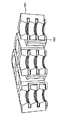
内部のペルチェ装置を有する実施例に係るNMSetもしくは関連するデバイスの断面が、図13及び図14に詳細図示される。すべての複数の加熱層1302が接続される。すべての複数の冷却層1301が接続される。電流は、複数の冷却層と複数の加熱層との間に置かれたペルチェ素子を通して流れ、温度差が確立される。複数の層はより薄くなればなるほど、より高い電流が必要となる。
A cross section of an NMSet or related device according to an embodiment having an internal Peltier device is illustrated in detail in FIGS. All the plurality of
内部のペルチェ装置を有するNMSetもしくは関連するデバイスは、デバイスのサイズを減少させることをより容易とさせる。図14に図示されたものなどの1つの積層は推進力を生成するために十分に機能的とすることができる。内部のペルチェ装置を有するNMSetもしくは関連するデバイスは、最大の粒度を増加させる複数のマイクロ電気機械システムにおける使用に適している。 NMSet or related devices with an internal Peltier device make it easier to reduce the size of the device. One stack, such as that illustrated in FIG. 14, can be sufficiently functional to generate a propulsion force. NMSet or related devices with internal Peltier devices are suitable for use in multiple microelectromechanical systems that increase maximum granularity.
電界により増強された熱イオン放出.
もう1つの実施形態において、温度差が、電界により増強された熱イオン放出により生成される。電界は、図19に図示されるように、冷却層1901から熱的に放出された複数の電荷キャリアが、熱を、冷却層1901から加熱層1902へと運ぶことができるように、複数の層1901と複数の層1902との間に確立される。
Thermionic emission enhanced by an electric field.
In another embodiment, the temperature difference is generated by thermionic emission enhanced by the electric field . Electric field, as shown in Figure 19, the
外部のペルチェ.
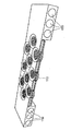
もう1つの実施形態において、温度差は、NMSetもしくは関連するデバイスに対して外部のペルチェ素子により生成される。図15及び図16に詳細図示されるように、このペルチェ素子(図示せず。)は、複数の界面層1510と複数の界面層1520とを介してNMSetもしくは関連するデバイスの積層1500に熱的に結合される。
External Peltier.
In another embodiment, the temperature difference is generated by a Peltier element external to the NMSet or related device. As illustrated in detail in FIGS. 15 and 16, this Peltier element (not shown) is thermally coupled to the NMSet or
外部のペルチェ素子を有するデバイスは、温度差を生成するために使用される複数の材料からの流体フローを生成するために使用される複数の材料を分離することの利益を有する。設計の観点からは、ペルチェ素子に適切な複数の材料が微細構造に適さなくてもよいし、もしくはその逆でもよいので、これが望ましいかもしれない。さらに、外部のペルチェ素子はより大きく、かつより効率的に作ることができ、十分な温度差を確立するための高電流を必要としない。 A device having an external Peltier element has the benefit of separating the materials used to generate the fluid flow from the materials used to generate the temperature difference. From a design point of view, this may be desirable because multiple materials suitable for Peltier elements may not be suitable for the microstructure or vice versa. Furthermore, the external Peltier element can be made larger and more efficient and does not require high currents to establish a sufficient temperature difference.
複数のピエゾ電気スペーサは、複数の層の間に使用される。NMSetにおける使用に適切な複数の材料は好ましくは、熱膨張及び収縮に機械的に十分に耐えることができるほど強く、並びに/または好ましくは非常に小さい複数の膨張係数を有する。そうでなければ、複数の層における複数の穴は位置がずらされて、それが効率性を減少させる。 A plurality of piezoelectric spacers are used between the plurality of layers. Materials suitable for use in NMSet are preferably strong enough to withstand mechanical expansion and contraction sufficiently and / or have a plurality of expansion coefficients that are preferably very small. Otherwise, the holes in the layers are shifted in position, which reduces efficiency.
外部の非ペルチェ.
まだもう1つの実施形態によれば、温度差は、任意の適切な加熱源及び/または複数の放熱板により確立される。例えば、複数の加熱源は、複数の抵抗加熱器、化学反応、燃焼、及び/または明るい光の直接的な照明であってもよい。そのような実施例の図が、図17に図示される。図示された実施例において、加熱表面1702は、抵抗加熱材料、すなわち放射加熱を効率的に受けることができる材料とすることができる。外部の非ペルチェ装置は、それがペルチェ素子を必要としないので、便利である。いくつかの複数の応用のために、放射を電気に最初に変換することよりもむしろ、加熱表面を例えば太陽などの放射の源の方向へ直接向けてペルチェ素子を駆動させることは便利かもしれない。代わりに、放射の源は、NMSetもしくは関連するデバイスの加熱層に熱伝達している熱吸収表面の方向に直接向けてもよい。しかしながら、外部の非ペルチェ装置において、好ましくは、NMSetもしくは関連するデバイスがオーバーヒート(過熱)されないことを確実にすることに注意が払われる。
External non-Peltier.
According to yet another embodiment, the temperature difference is established by any suitable heating source and / or multiple heat sinks. For example, the multiple heating sources may be multiple resistance heaters, chemical reactions, combustion, and / or direct illumination of bright light. A diagram of such an embodiment is illustrated in FIG. In the illustrated embodiment, the
図17に図示される複数のキャピラリは、放熱板が提供される例示的なメカニズム(機構)である。しかしながら、放熱板を簡単に一連の翼、すなわち任意の他の適切な複数の放熱板とすることも可能である。代わりに、図17における外部の非ペルチェ装置は、複数のキャピラリ1750により加熱源を提供するように構成される。加熱源は、発熱化学反応とすることができ、好ましくは過剰な圧力を生成しない発熱化学反応とすることができる。
The plurality of capillaries illustrated in FIG. 17 is an exemplary mechanism in which a heat sink is provided. However, it is also possible for the heat sink to simply be a series of blades, ie any other suitable heat sink. Instead, the external non-Peltier device in FIG. 17 is configured to provide a heating source with a plurality of
材料.
NMSet及び関連する複数のデバイスは、広い範囲の複数の材料から作られてもよい。種々の複数の態様において、複数の材料の複数の特性は、望ましい複数の幾何学的形状と組み合わせて利用されてもよい。
material.
The NMSet and associated devices may be made from a wide range of materials. In various aspects, the properties of the materials may be utilized in combination with the desired geometric shapes.
複数のガス分子の正反射性反射は、例えば、フローガスと接触する加熱された複数の表面及び冷却された複数の表面などの、NMSetもしくは関連するデバイスのガスに露出された複数の表面を形成する複数の材料の望ましい特性である。正反射性反射は、鏡のような光の反射であり、すなわちこの場合は複数のガス粒子の反射であり、ある表面から反射される。正反射性表面に関し、1つの入射角度での複数の入射ガス粒子は、表面から1つの出射角度の中へと反射される。もし複数の入射ガス粒子と表面とが同一の温度を有するならば、表面法線に対して入射角度と出射角度とは同一である。すなわち、入射の角度は出射の角度と等しい。正反射性反射の第2の定義される特性は、入射と、法線と、反射された複数の方向とが同一平面上にあるということである。もし複数の入射ガス粒子と表面とが同一の温度でなく、非断熱(すなわち、複数のガス粒子と表面との間の熱交換を用いて)であるならば、反射の角度は表面と複数のガス粒子との間を移動した熱の関数である。 The specular reflection of multiple gas molecules forms multiple surfaces exposed to the gas of the NMSet or related device, for example, heated surfaces in contact with the flow gas and cooled surfaces This is a desirable property of multiple materials. A specular reflection is a mirror-like reflection of light, in this case a reflection of a plurality of gas particles, reflected from a surface. For a specular surface, multiple incident gas particles at one incident angle are reflected from the surface into one exit angle. If the plurality of incident gas particles and the surface have the same temperature, the incident angle and the outgoing angle with respect to the surface normal are the same. That is, the incident angle is equal to the outgoing angle. A second defined characteristic of specular reflection is that the incidence, normal, and reflected directions are in the same plane. If the incident gas particles and the surface are not at the same temperature and are non-adiabatic (ie, using heat exchange between the gas particles and the surface), the angle of reflection is It is a function of heat transferred between gas particles.
材料の鏡面性の程度が、位相空間の単位体積あたりの複数のガス粒子の反射された状態の確率密度関数と定義された(例えば、サーシガナニ−ランピス カーネル(Cercignani−Lampis kernel)などの)反射カーネルにより表される。反射カーネルの詳細が非特許文献2及びこの中に掲載された複数の参考文献に開示され、それらのすべてがここにより参照によりここに組み込まれる。 The degree of specularity of the material is defined as the probability density function of the reflected state of a plurality of gas particles per unit volume of phase space (e.g., such as the Cercignani-Lampis kernel) It is represented by Details of the reflection kernel are disclosed in Non-Patent Document 2 and the references cited therein, all of which are hereby incorporated herein by reference.
個々の加熱層及び冷却層がまた、例えば剛性を比較するための手段などの構造的な複数の材料と、例えば温度差生成手段へと熱を移動させ、及び温度差生成手段から熱を移動させる熱移動のための手段などの熱伝導性材料と、例えば望ましい複数の反射カーネル特性を提供するための手段などの原子反射材料とを構成することができる1つもしくはそれ以上の構造的な要素から作られる。いくつかの複数の実施形態において、個々の加熱層及び冷却層はそのような複数の材料の層状の混合物から作られてもよい。 The individual heating and cooling layers also transfer heat to and from the structural difference material, for example, means for comparing the rigidity, for example, to the temperature difference generating means, and transfer heat from the temperature difference generating means. From one or more structural elements that can constitute a thermally conductive material, such as a means for heat transfer, and an atomic reflective material, such as, for example, a means for providing a desired plurality of reflective kernel properties Made. In some embodiments, the individual heating and cooling layers may be made from a layered mixture of such materials.
従って、複数の材料の選択と混合は広く可変的である。いくつかの複数の実施形態において、NMSetもしくは関連するデバイスの構造に適切な複数の材料は、チタニウム、シリコン、鋼鉄(スチール)、及び/または鉄を含むことができる。チタニウムは軽量で六角形の結晶構造を持つ。チタニウムの複数の界面は、結晶の歪みなしの直交角度で形成されてもよく、従ってストレス限界はない。チタニウムの複数の材料コスト(費用)は高い。シリコンは高価でなく、複数の特性及び機械加工のための複数の処理が十分に理解されている。シリコンの結晶構造は、ダイアモンド立方体(キュービック)である。鋼鉄は、チタニウムよりも安価であり、立方体結晶構造を有し、ガスの侵入に対する高い抵抗力がある。鉄は、鋼鉄よりも安価であり、NMSet及び関連する複数のデバイスにおける応用に適した結晶構造を有する。 Thus, the selection and mixing of multiple materials is widely variable. In some embodiments, the plurality of materials suitable for the structure of the NMSet or related device can include titanium, silicon, steel, and / or iron. Titanium is lightweight and has a hexagonal crystal structure. The multiple interfaces of titanium may be formed at orthogonal angles without crystal distortion and therefore have no stress limit. The cost of multiple materials for titanium is high. Silicon is not expensive and multiple properties and multiple processes for machining are well understood. The crystal structure of silicon is a diamond cube (cubic). Steel is less expensive than titanium, has a cubic crystal structure, and is highly resistant to gas ingress. Iron is less expensive than steel and has a crystalline structure suitable for application in NMSet and related devices.
NMSetもしくは関連するデバイスを製造する例示的な方法.
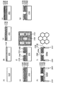
図20に図示されたある実施形態によれば、NMSetもしくは関連するデバイスを製造する方法は、以下から構成される。
(a)例えば、アモルファス(非結晶)シリコン、結晶シリコン、セラミックなどの適切な基板2001を提供し、基板2001は好ましくは、500μmから1500μmの厚さを有する。
(b)例えば、二酸化シリコンなどの第1の層2002を堆積し、第1の層2002は好ましくは、200nmから50μmの厚さを有する。
(c)第1の層2002をフォトリソグラフィしてエッチングすることにより、第1の層から、例えばストリップ(薄い層,細長い一片)、正方形(スクエア)、円などの任意の適切な形状の別個の複数の島を形成すること。
(d)別個の複数の島の上に第2の層2003を堆積し、第2の層2003は、例えばアルミニウム(Al)、ニオブ(Nb)もしくは亜鉛(Zn)などの導電体である。
(e)第2の層2003の上に第3の層2004を堆積して、第3の層2004は、例えば二酸化シリコンなどの電気絶縁体である。
(f)第1の層2002が露出されるまで第3の層2004を部分的に除去すること。
(g)第4の層2005を堆積し、第4の層2005は、例えば二酸化シリコンなどの電気絶縁体であり、第4の層2005は好ましくは、3nmから15nmの厚さを有する。
(h)第5の層2006を堆積し、第5の層2006は、例えば白金(Pt)、ニッケル(Ni)もしくは銅(Cu)などの導電体で、好ましくは50nmから200nmの厚さを有する。
(i)例えば二酸化シリコンなどの第6の層2007を堆積し、第6の層2007は好ましくは500μmから1500μmの厚さを有する。
(j)第1の層2002のうちの少なくとも1つの別個の島がそこに露出されるように、基板2001をフォトリソグラフィしてエッチングすることにより、基板2001の中に複数のスルーホール2001aを形成し、
複数のスルーホール2001aは、例えば複数の六角形、複数の正方形及び複数の円などの任意の適切な形状を有し、
複数のスルーホール2001aは、例えば六角形のグリッド、正方形のグリッド及び極性のグリッドなどの任意の適切なパタンで配列される。
(k)それらの上の第4の層2005を複数の部分が露出されるまでエッチングすることにより、露出された別個の複数の島を除去すること。
(l)それらの上の第5の層2006の複数の部分が露出されるまで第4の層2005の露出された部分を除去すること。
(m)エッチングにより、第5の層2006の露出された複数の部分を除去すること。
(n)第2の層2003と第5の層2006とが第4の層2005よりも突き出る(オーバーハングする)ように、横方向にエッチングすることにより、第4の層2005を部分的に除去すること。
(o)エッチングにより、第6の層2007を完全に除去すること。
An exemplary method of manufacturing a NMSet or related device.
According to one embodiment illustrated in FIG. 20, the method of manufacturing the NMSet or related device consists of:
(A) A
(B) depositing a
(C) by photolithographically etching the
(D) A
(E) A
(F) The
(G) Depositing a
(H) A
(I) Depositing a
(J) Forming a plurality of through
The plurality of through
The plurality of through
(K) removing the exposed discrete islands by etching the
(L) removing the exposed portions of the
(M) removing a plurality of exposed portions of the
(N) The
(O) The
第2の層2003と第5の層2006は好ましくは、それらの仕事関数において、少なくとも1eV、少なくとも2eV、もしくは少なくとも3eVの差を有する。
The
図21に図示されたもう1つの実施形態によれば、NMSetもしくは関連するデバイスを製造する方法は、以下から構成される。
(a)例えば、アモルファスシリコン、結晶シリコン、セラミックなどの適切な基板2101を提供し、基板2101は好ましくは、500μmから1500μmの厚さを有する。
(b)例えば、二酸化シリコンなどの第1の層2102を堆積し、第1の層2102は好ましくは、50nmから1000nmの厚さを有する。
(c)第1の層2102の上に第2の層2103を堆積し、第2の層は、例えばアルミニウム(Al)、ニオブ(Nb)もしくは亜鉛(Zn)などの導電体であり、好ましくは50nmから150nmの厚さを有する。
(d)第2の層2103の上に第3の層2104を堆積し、第3の層2104は、例えば二酸化シリコンなどの電気絶縁体であり、好ましくは50nmから100nmの厚さを有する。
(e)第3の層2104の上に第4の層2105を堆積し、第4の層2105は、例えば白金(Pt)、ニッケル(Ni)もしくは銅(Cu)などの導電体で、好ましくは50nmから150nmの厚さを有する。
(f)フォトリソグラフィしてエッチングすることにより、第2の層2103と第3の層2104と第4の層2105とを通り抜けた複数の穴を形成し、複数の穴は、例えば複数のストリップ、複数の正方形、複数の円などの任意の適切な形状を有する。
(g)第2の層2103と第4の層2105とが第3の層2104よりも突き出る(オーバーハングする)ように、横方向にエッチングすることにより、第3の層2104を部分的に除去すること。
(h)第2の層2103と第3の層2104と第4の層2105とを通り抜けた少なくとも1つの穴が、1つのスルーホール2101aと重なるように、基板2101をフォトリソグラフィしてエッチングすることにより、基板2101において複数のスルーホール2101aを形成し、
複数のスルーホール2101aは、例えば複数の六角形、複数の正方形及び複数の円などの任意の適切な形状を有し、
複数のスルーホール2101aは、例えば六角形のグリッド、正方形のグリッド及び極性のグリッドなどの任意の適切なパタンで配列される。
(i)複数のスルーホール2101aの中で露出された第1の層2102の複数の部分を除去すること。
According to another embodiment illustrated in FIG. 21, the method of manufacturing NMSet or related devices consists of:
(A) A
(B) depositing a
(C) depositing a
(D) A
(E) A
(F) A plurality of holes that pass through the
(G) The
(H) etching the
The plurality of through
The plurality of through
(I) removing a plurality of portions of the
第2の層2103と第4の層2105は好ましくは、それらの仕事関数において、少なくとも1eV、少なくとも2eV、もしくは少なくとも3eVの差を有する。
The
複数のNMSet及び関連するデバイスが、それらの特定の複数の実施形態を参照して詳細に説明される一方で、種々の複数の変更及び複数の変形がなされ、添付された特許請求の範囲の範囲を離れることなしに、複数の均等物が採用されることが当業者には自明となろう。 While multiple NMSets and associated devices are described in detail with reference to specific embodiments thereof, various modifications and variations can be made and the scope of the appended claims It will be apparent to those skilled in the art that multiple equivalents can be employed without departing from the scope.
Claims (14)
積層された第1の層と第2の層と、
上記第1の層と上記第2の層を加熱し、及び/または冷却して、加熱層及び上記加熱層よりもより低温度を有する冷却層を形成するための手段と、
上記積層において少なくとも1つのスルーホールとを備え、
上記加熱層の表面は上記スルーホールの内部において露出され、上記冷却層の表面は上記スルーホールの内部において露出され、
上記手段は、上記加熱層を上記ガスの周囲温度よりも熱くなるように制御し、上記冷却層を上記ガスの周囲温度よりも冷たくなるように制御し、
上記加熱層は、内側に向いてかつ第1の方向に面している面を有し、上記加熱層の面と上記スルーホールの中心軸との間の角度がθ 2 であり、
上記冷却層は、内側に向いてかつ上記第1の方向に対向する第2の方向である面を有し、上記冷却層の面と上記スルーホールの中心軸との間の角度がθ 1 であることを特徴とする請求項1記載の装置。 An apparatus operable to create a temperature difference for propelling a flow of gas,
A first layer and a second layer laminated;
Means for heating and / or cooling the first layer and the second layer to form a heating layer and a cooling layer having a lower temperature than the heating layer;
Comprising at least one through hole in the stack,
The surface of the heating layer is exposed inside the through hole, the surface of the cooling layer is exposed inside the through hole,
The means controls the heating layer to be hotter than the ambient temperature of the gas, and controls the cooling layer to be cooler than the ambient temperature of the gas.
The heating layer has a surface facing inward and facing the first direction, and an angle between the surface of the heating layer and the central axis of the through hole is θ 2 ,
The cooling layer has a surface that is inward and has a second direction facing the first direction, and an angle between the surface of the cooling layer and the central axis of the through hole is θ 1 . the apparatus of claim 1, wherein the certain.
上記複数の加熱層は、すぐ隣接した上記複数の冷却層よりも熱く、上記複数の冷却層は、すぐ隣接した上記複数の加熱層よりも冷たく、上記少なくとも1つのスルーホールが上記積層において上記第1の装置及び上記第2の装置を通り抜けて延在することを特徴とする装置。 2. An apparatus comprising at least two devices according to claim 1, wherein both the first device and the second device of the at least two devices comprise a heating layer and a cooling layer, the at least two devices. The heating layer and the cooling layer of the first device and the heating layer and the cooling layer of the second device form an alternating stack of the plurality of heating layers and the plurality of cooling layers. Arranged so that you can
The plurality of heating layers are hotter than the immediately adjacent cooling layers, the plurality of cooling layers are cooler than the immediately adjacent heating layers, and the at least one through hole is the first layer in the stack. A device extending through the first device and the second device.
上記装置を、周囲温度及び圧力におけるガスに対して露出させるステップと、
上記ガスフローが上記スルーホールを通って推進されるように、交互の複数の層を加熱し、及び/または冷却して交互の上記加熱層及び上記冷却層を形成する手段を動作させるステップとを含むことを特徴とする方法。 A method of using the apparatus of claim 1, wherein the method comprises:
Exposing the apparatus to gas at ambient temperature and pressure;
Heating the alternating layers and / or cooling to operate the means for forming the alternating heating and cooling layers such that the gas flow is propelled through the through-holes. A method characterized by comprising.
Applications Claiming Priority (6)
| Application Number | Priority Date | Filing Date | Title |
|---|---|---|---|
| US23944609P | 2009-09-03 | 2009-09-03 | |
| US61/239,446 | 2009-09-03 | ||
| US26477809P | 2009-11-27 | 2009-11-27 | |
| US61/264,778 | 2009-11-27 | ||
| US29619810P | 2010-01-19 | 2010-01-19 | |
| US61/296,198 | 2010-01-19 |
Related Parent Applications (1)
| Application Number | Title | Priority Date | Filing Date |
|---|---|---|---|
| JP2012527867A Division JP2013504008A (en) | 2009-09-03 | 2010-09-03 | Nanomolecular solid-state electric thruster |
Publications (2)
| Publication Number | Publication Date |
|---|---|
| JP2016188646A JP2016188646A (en) | 2016-11-04 |
| JP6218892B2 true JP6218892B2 (en) | 2017-10-25 |
Family
ID=43649846
Family Applications (2)
| Application Number | Title | Priority Date | Filing Date |
|---|---|---|---|
| JP2012527867A Pending JP2013504008A (en) | 2009-09-03 | 2010-09-03 | Nanomolecular solid-state electric thruster |
| JP2016126718A Expired - Fee Related JP6218892B2 (en) | 2009-09-03 | 2016-06-27 | Nanomolecular solid-state electric thruster |
Family Applications Before (1)
| Application Number | Title | Priority Date | Filing Date |
|---|---|---|---|
| JP2012527867A Pending JP2013504008A (en) | 2009-09-03 | 2010-09-03 | Nanomolecular solid-state electric thruster |
Country Status (9)
| Country | Link |
|---|---|
| US (3) | US9006612B2 (en) |
| EP (1) | EP2473785B1 (en) |
| JP (2) | JP2013504008A (en) |
| KR (1) | KR101714510B1 (en) |
| CN (1) | CN102639940B (en) |
| IL (1) | IL218425A (en) |
| IN (1) | IN2012DN02800A (en) |
| RU (1) | RU2535593C2 (en) |
| WO (1) | WO2011028287A2 (en) |
Families Citing this family (15)
| Publication number | Priority date | Publication date | Assignee | Title |
|---|---|---|---|---|
| WO2012118990A1 (en) | 2011-03-02 | 2012-09-07 | Game Changers, Llc | Apparatus and methods for evacuating air from a closed area |
| US9192882B2 (en) * | 2009-09-03 | 2015-11-24 | Game Changers Llc | Apparatus and methods using non-fouling bypass filter |
| WO2012119034A2 (en) * | 2011-03-02 | 2012-09-07 | Game Changers, Llc | Method and apparatus for a dynamic air cushion transport system |
| JP2014512294A (en) * | 2011-03-02 | 2014-05-22 | ゲーム・チェンジャーズ・リミテッド・ライアビリティ・カンパニー | Air cushion transport |
| WO2012118994A2 (en) * | 2011-03-02 | 2012-09-07 | Game Changers, Llc | Fault tolerant control system for distributed micro-thrusters |
| EP2681116A4 (en) * | 2011-03-02 | 2014-10-15 | Game Changers Llc | Flight control using distributed micro-thrusters |
| FR2972571A1 (en) * | 2011-03-09 | 2012-09-14 | St Microelectronics Crolles 2 | THERMOELECTRIC GENERATOR |
| EP2861859B1 (en) * | 2012-06-15 | 2018-03-21 | Game Changers, Llc | Micro thruster uses and improvements |
| WO2014160361A1 (en) * | 2013-03-14 | 2014-10-02 | Steinhour Leif Alexi | Convection pump and method of operation |
| US9683474B2 (en) | 2013-08-30 | 2017-06-20 | Dürr Systems Inc. | Block channel geometries and arrangements of thermal oxidizers |
| WO2016081047A2 (en) * | 2014-09-03 | 2016-05-26 | Pacific Scientific Energetic Materials Company | Propulsion system comprising plurality of individually selectable solid fuel motors |
| US9761781B2 (en) * | 2014-11-29 | 2017-09-12 | Hyundai Motor Company | Thermoelectric generator sleeve for a catalytic converter |
| AU2020281012B1 (en) * | 2020-12-01 | 2021-06-17 | Soliton Holdings Corporation, Delaware Corporation | Apparatuses Based on Jet-Effect and Thermoelectric Effect |
| WO2023039173A1 (en) * | 2021-09-09 | 2023-03-16 | Torramics, Inc. | Apparatus and method of operating a gas pump |
| US11767828B2 (en) | 2023-03-27 | 2023-09-26 | Daniel L. Amend | Light turbine, turbine, and turbine housing for vane evaluation |
Family Cites Families (13)
| Publication number | Priority date | Publication date | Assignee | Title |
|---|---|---|---|---|
| GB8609228D0 (en) * | 1986-04-16 | 1986-05-21 | Marconi Co Ltd | Thrusters |
| US6984273B1 (en) * | 1999-07-29 | 2006-01-10 | Aerojet-General Corporation | Premixed liquid monopropellant solutions and mixtures |
| US6378292B1 (en) * | 2000-11-10 | 2002-04-30 | Honeywell International Inc. | MEMS microthruster array |
| US6692700B2 (en) * | 2001-02-14 | 2004-02-17 | Handylab, Inc. | Heat-reduction methods and systems related to microfluidic devices |
| US6752601B2 (en) * | 2001-04-06 | 2004-06-22 | Ngk Insulators, Ltd. | Micropump |
| DE60213085T2 (en) * | 2001-05-23 | 2007-02-15 | Svenska Rymdaktiebolaget | REACTOR FOR THE DECOMPOSITION OF LIQUID MONERGOL FUELS ON AMMONIUM DINITIRID BASE AND DECOMPOSITION PROCESS |
| JP4766797B2 (en) | 2001-08-14 | 2011-09-07 | 株式会社東京精密 | Prober stage structure |
| DE10240639B3 (en) * | 2002-09-03 | 2004-02-12 | Trw Airbag Systems Gmbh & Co. Kg | Vehicle airbag gas generator with long cylindrical casing, has external igniter units producing gas which flows into distribution chambers in cylinder |
| US7069733B2 (en) * | 2003-07-30 | 2006-07-04 | Air Products And Chemicals, Inc. | Utilization of bogdown of single-shaft gas turbines to minimize relief flows in baseload LNG plants |
| WO2005068066A1 (en) | 2004-01-20 | 2005-07-28 | Sosho, Inc. | Temperature controller and protein crystallizer utilizing the same |
| US20060001569A1 (en) | 2004-07-01 | 2006-01-05 | Marco Scandurra | Radiometric propulsion system |
| US7690187B2 (en) * | 2006-09-26 | 2010-04-06 | The Aerospace Corporation | Modular micropropulsion device and system |
| US20090151434A1 (en) * | 2007-12-17 | 2009-06-18 | Samsung Electronics Co., Ltd | Apparatus and method using a disk drive slider and/or a peltier plate in an atomic force microscope |
-
2010
- 2010-09-03 CN CN201080049375.7A patent/CN102639940B/en not_active Expired - Fee Related
- 2010-09-03 WO PCT/US2010/002428 patent/WO2011028287A2/en active Application Filing
- 2010-09-03 EP EP10814092.2A patent/EP2473785B1/en not_active Not-in-force
- 2010-09-03 RU RU2012112828/06A patent/RU2535593C2/en not_active IP Right Cessation
- 2010-09-03 KR KR1020127007235A patent/KR101714510B1/en active IP Right Grant
- 2010-09-03 JP JP2012527867A patent/JP2013504008A/en active Pending
- 2010-09-03 IN IN2800DEN2012 patent/IN2012DN02800A/en unknown
-
2011
- 2011-03-02 US US13/039,238 patent/US9006612B2/en not_active Expired - Fee Related
-
2012
- 2012-03-01 IL IL21842512A patent/IL218425A/en not_active IP Right Cessation
- 2012-03-02 US US13/410,798 patent/US8794930B2/en not_active Expired - Fee Related
-
2014
- 2014-06-20 US US14/310,482 patent/US9845796B2/en not_active Expired - Fee Related
-
2016
- 2016-06-27 JP JP2016126718A patent/JP6218892B2/en not_active Expired - Fee Related
Also Published As
| Publication number | Publication date |
|---|---|
| US20110240622A1 (en) | 2011-10-06 |
| KR20120079833A (en) | 2012-07-13 |
| CN102639940B (en) | 2014-08-06 |
| WO2011028287A2 (en) | 2011-03-10 |
| US20150247492A1 (en) | 2015-09-03 |
| IN2012DN02800A (en) | 2015-07-24 |
| EP2473785B1 (en) | 2018-06-13 |
| JP2016188646A (en) | 2016-11-04 |
| US20120237364A1 (en) | 2012-09-20 |
| US9845796B2 (en) | 2017-12-19 |
| KR101714510B1 (en) | 2017-03-09 |
| US8794930B2 (en) | 2014-08-05 |
| RU2012112828A (en) | 2013-10-10 |
| IL218425A (en) | 2014-07-31 |
| JP2013504008A (en) | 2013-02-04 |
| RU2535593C2 (en) | 2014-12-20 |
| EP2473785A2 (en) | 2012-07-11 |
| US9006612B2 (en) | 2015-04-14 |
| EP2473785A4 (en) | 2015-04-29 |
| IL218425A0 (en) | 2012-04-30 |
| WO2011028287A3 (en) | 2011-06-03 |
| CN102639940A (en) | 2012-08-15 |
Similar Documents
| Publication | Publication Date | Title |
|---|---|---|
| JP6218892B2 (en) | Nanomolecular solid-state electric thruster | |
| KR20140015425A (en) | Air cushion transport | |
| JP6038819B2 (en) | Vehicle movement control method, movement control device, non-transitory computer storage medium, and flight control system | |
| JP2014510230A (en) | Distributed thruster driven gas compressor | |
| US9728699B2 (en) | Thermal transpiration device and method of making same | |
| JP6046645B2 (en) | Fault tolerant control system for distributed microcluster | |
| US9551293B2 (en) | Replaceable thrust generating structures attached to an air vehicle | |
| EP2861859B1 (en) | Micro thruster uses and improvements | |
| US9404487B2 (en) | Apparatus and methods for evacuating air from a closed area | |
| WO2012119036A1 (en) | An article separation system using a plurality of vortexes |
Legal Events
| Date | Code | Title | Description |
|---|---|---|---|
| A131 | Notification of reasons for refusal |
Free format text: JAPANESE INTERMEDIATE CODE: A131 Effective date: 20170530 |
|
| A521 | Request for written amendment filed |
Free format text: JAPANESE INTERMEDIATE CODE: A523 Effective date: 20170824 |
|
| TRDD | Decision of grant or rejection written | ||
| A01 | Written decision to grant a patent or to grant a registration (utility model) |
Free format text: JAPANESE INTERMEDIATE CODE: A01 Effective date: 20170905 |
|
| A61 | First payment of annual fees (during grant procedure) |
Free format text: JAPANESE INTERMEDIATE CODE: A61 Effective date: 20170926 |
|
| R150 | Certificate of patent or registration of utility model |
Ref document number: 6218892 Country of ref document: JP Free format text: JAPANESE INTERMEDIATE CODE: R150 |
|
| LAPS | Cancellation because of no payment of annual fees |