JP6201580B2 - Storage control device, storage control method, and storage control program - Google Patents
Storage control device, storage control method, and storage control program Download PDFInfo
- Publication number
- JP6201580B2 JP6201580B2 JP2013202071A JP2013202071A JP6201580B2 JP 6201580 B2 JP6201580 B2 JP 6201580B2 JP 2013202071 A JP2013202071 A JP 2013202071A JP 2013202071 A JP2013202071 A JP 2013202071A JP 6201580 B2 JP6201580 B2 JP 6201580B2
- Authority
- JP
- Japan
- Prior art keywords
- identifier
- volume
- unit
- storage device
- vdisk
- Prior art date
- Legal status (The legal status is an assumption and is not a legal conclusion. Google has not performed a legal analysis and makes no representation as to the accuracy of the status listed.)
- Expired - Fee Related
Links
Images


Classifications
-
- G—PHYSICS
- G06—COMPUTING; CALCULATING OR COUNTING
- G06F—ELECTRIC DIGITAL DATA PROCESSING
- G06F3/00—Input arrangements for transferring data to be processed into a form capable of being handled by the computer; Output arrangements for transferring data from processing unit to output unit, e.g. interface arrangements
- G06F3/06—Digital input from, or digital output to, record carriers, e.g. RAID, emulated record carriers or networked record carriers
- G06F3/0601—Interfaces specially adapted for storage systems
- G06F3/0628—Interfaces specially adapted for storage systems making use of a particular technique
- G06F3/0646—Horizontal data movement in storage systems, i.e. moving data in between storage devices or systems
- G06F3/065—Replication mechanisms
-
- G—PHYSICS
- G06—COMPUTING; CALCULATING OR COUNTING
- G06F—ELECTRIC DIGITAL DATA PROCESSING
- G06F3/00—Input arrangements for transferring data to be processed into a form capable of being handled by the computer; Output arrangements for transferring data from processing unit to output unit, e.g. interface arrangements
- G06F3/06—Digital input from, or digital output to, record carriers, e.g. RAID, emulated record carriers or networked record carriers
- G06F3/0601—Interfaces specially adapted for storage systems
- G06F3/0602—Interfaces specially adapted for storage systems specifically adapted to achieve a particular effect
- G06F3/0604—Improving or facilitating administration, e.g. storage management
- G06F3/0605—Improving or facilitating administration, e.g. storage management by facilitating the interaction with a user or administrator
-
- G—PHYSICS
- G06—COMPUTING; CALCULATING OR COUNTING
- G06F—ELECTRIC DIGITAL DATA PROCESSING
- G06F3/00—Input arrangements for transferring data to be processed into a form capable of being handled by the computer; Output arrangements for transferring data from processing unit to output unit, e.g. interface arrangements
- G06F3/06—Digital input from, or digital output to, record carriers, e.g. RAID, emulated record carriers or networked record carriers
- G06F3/0601—Interfaces specially adapted for storage systems
- G06F3/0602—Interfaces specially adapted for storage systems specifically adapted to achieve a particular effect
- G06F3/0614—Improving the reliability of storage systems
- G06F3/0617—Improving the reliability of storage systems in relation to availability
-
- G—PHYSICS
- G06—COMPUTING; CALCULATING OR COUNTING
- G06F—ELECTRIC DIGITAL DATA PROCESSING
- G06F3/00—Input arrangements for transferring data to be processed into a form capable of being handled by the computer; Output arrangements for transferring data from processing unit to output unit, e.g. interface arrangements
- G06F3/06—Digital input from, or digital output to, record carriers, e.g. RAID, emulated record carriers or networked record carriers
- G06F3/0601—Interfaces specially adapted for storage systems
- G06F3/0628—Interfaces specially adapted for storage systems making use of a particular technique
- G06F3/0662—Virtualisation aspects
- G06F3/0664—Virtualisation aspects at device level, e.g. emulation of a storage device or system
-
- G—PHYSICS
- G06—COMPUTING; CALCULATING OR COUNTING
- G06F—ELECTRIC DIGITAL DATA PROCESSING
- G06F3/00—Input arrangements for transferring data to be processed into a form capable of being handled by the computer; Output arrangements for transferring data from processing unit to output unit, e.g. interface arrangements
- G06F3/06—Digital input from, or digital output to, record carriers, e.g. RAID, emulated record carriers or networked record carriers
- G06F3/0601—Interfaces specially adapted for storage systems
- G06F3/0628—Interfaces specially adapted for storage systems making use of a particular technique
- G06F3/0662—Virtualisation aspects
- G06F3/0665—Virtualisation aspects at area level, e.g. provisioning of virtual or logical volumes
-
- G—PHYSICS
- G06—COMPUTING; CALCULATING OR COUNTING
- G06F—ELECTRIC DIGITAL DATA PROCESSING
- G06F3/00—Input arrangements for transferring data to be processed into a form capable of being handled by the computer; Output arrangements for transferring data from processing unit to output unit, e.g. interface arrangements
- G06F3/06—Digital input from, or digital output to, record carriers, e.g. RAID, emulated record carriers or networked record carriers
- G06F3/0601—Interfaces specially adapted for storage systems
- G06F3/0668—Interfaces specially adapted for storage systems adopting a particular infrastructure
- G06F3/0671—In-line storage system
- G06F3/0683—Plurality of storage devices
- G06F3/0689—Disk arrays, e.g. RAID, JBOD
Description
本発明は、ストレージ制御装置、ストレージ制御方法及びストレージ制御プログラムに関する。 The present invention relates to a storage control device, a storage control method, and a storage control program.
従来、物理的な記憶装置のボリューム構成や記憶容量に制限されることなく、自由なボリューム構成、記憶容量の記憶装置を実現することができるストレージシステムとして、仮想化環境向けストレージ、いわゆる仮想化ストレージ装置が使用されている。仮想化ストレージ装置は、装置内部に物理的な記憶装置に対するアクセスを制御する実ストレージ装置(Storage Unit;実SU、或いは単にSUとも呼ぶ)を有する。そして、実ストレージ装置を管理するプロセッサユニット(Processor Unit;PU)が、仮想的なボリューム(以降、VDISKとも呼ぶ)を作成し、VDISKの仮想的な記憶領域に対して実ストレージ装置の物理的な記憶領域が割り当てられる。 Conventionally, as a storage system that can realize a storage device having a free volume configuration and storage capacity without being limited by the volume configuration and storage capacity of a physical storage device, storage for virtual environments, so-called virtualization storage The device is in use. The virtual storage apparatus has a real storage apparatus (Storage Unit; also referred to as real SU or simply SU) that controls access to a physical storage device. Then, a processor unit (PU) that manages the real storage device creates a virtual volume (hereinafter also referred to as VDISK), and physically stores the real storage device with respect to the virtual storage area of the VDISK. A storage area is allocated.
例えば、実SUが4つのRedundant Arrays of Inexpensive Disks(RAID)グループをそなえ、容量1テラバイト(TB)の8つのLogical Unit(LUN)をそなえる仮想化ストレージ装置の例を考える。この仮想化ストレージ装置は、実LUN数及び実LUNサイズに依存することなく、業務に用いられるサーバである業務サーバに対して、任意のVDISKを提供することができ、例えば100GBのボリュームを80個提供できる。 For example, consider an example of a virtual storage device in which a real SU has four Redundant Arrays of Inexpensive Disks (RAID) groups and eight logical units (LUNs) with a capacity of 1 terabyte (TB). This virtual storage apparatus can provide an arbitrary VDISK to a business server that is a server used for business without depending on the number of actual LUNs and the actual LUN size. For example, 80 volumes of 100 GB are provided. Can be provided.
ところで、このような仮想化ストレージ装置には、仮想化ストレージ装置に追加の記憶容量が必要となったときに、仮想化ストレージ装置全体の記憶領域を拡張できるものがある。例えば、実ストレージ装置を管理するPU及びSUの単位で拡張することができる仮想化ストレージ装置が存在する。このように1つのPUと1つのSUとを1セットとする拡張セット(PU+SU)を、仮想化ストレージ装置に追加することを「スケールアウト」と呼ぶ。又、スケールアウト可能な仮想化ストレージ装置を、「スケールアウト型仮想化ストレージ装置」と呼ぶ。 By the way, some of such virtual storage apparatuses can expand the storage area of the entire virtual storage apparatus when the virtual storage apparatus needs additional storage capacity. For example, there is a virtual storage apparatus that can be expanded in units of PUs and SUs that manage real storage apparatuses. Adding an expansion set (PU + SU) that includes one PU and one SU in this way to the virtual storage apparatus is called “scale-out”. A virtual storage apparatus that can be scaled out is referred to as a “scale-out virtual storage apparatus”.
一方、情報処理システム全体の信頼性を向上させるために、災害発生やシステムの入れ替えに備えて、上記の如き仮想化ストレージ装置を、例えば地理的に離れた地点(サイト)に複数設けることがある。
この構成では、業務サーバによって使用される仮想化ストレージ装置が設置されているサイトをローカルサイト、プライマリサイト、又は主系サイトと呼び、予備の仮想化ストレージ装置が設置されているサイトをリモートサイト、セカンダリサイト、又は従系サイトと呼ぶ。そして、プライマリサイトとリモートサイトとの2つの仮想化ストレージ装置のPU同士が、スイッチ(SW)等を介してデータ転送用の回線で接続されている。そして、例えばローカルサイトの被災にそなえて、ローカルサイトのデータが、リモートコピー(RemoteCopy;RC)セッションなどを実行することにより、リモートサイトにコピー(バックアップ)される。
On the other hand, in order to improve the reliability of the entire information processing system, a plurality of virtual storage apparatuses as described above may be provided at geographically distant points (sites) in preparation for disaster occurrence or system replacement. .
In this configuration, the site where the virtual storage device used by the business server is installed is called a local site, primary site, or primary site, and the site where the spare virtual storage device is installed is a remote site, Called secondary site or subordinate site. The PUs of the two virtual storage apparatuses at the primary site and the remote site are connected to each other by a data transfer line via a switch (SW) or the like. For example, in preparation for a disaster at the local site, the local site data is copied (backed up) to the remote site by executing a remote copy (RC) session or the like.
ローカルサイトの被災時に、リモートサイトにコピーしたデータを利用して業務を継続するには、まず、リモートコピーセッションを削除する。この理由は、リモートコピーセッションが張られた状態では、セカンダリサイトのVDISKへのWriteアクセスができないためである。
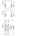
図20は、従来の仮想化ストレージシステムにおけるローカルサイト被災時のサイト切替処理を示す図である
ステップS101において、ローカルサイトが被災する。
To continue operations using data copied to the remote site in the event of a disaster at the local site, first delete the remote copy session. This is because when a remote copy session is established, Write access to the VDISK at the secondary site is not possible.
FIG. 20 is a diagram showing site switching processing at the time of a local site disaster in the conventional virtual storage system. In step S101, the local site is damaged.
ステップS102において、情報処理システムの運用管理者が、リモートサイトにある管理サーバ上で、WebGUI又はコマンドラインインタフェース(Command Line Interface;CLI)を用いて仮想化ストレージ装置のリモートコピーのスケジュール停止を指示する。
ステップS103において、リモートサイトの仮想化ストレージ装置のリモートコピーのスケジュールが停止される。
In step S102, the operation manager of the information processing system gives an instruction to stop the remote copy schedule of the virtual storage apparatus using the Web GUI or the command line interface (CLI) on the management server at the remote site. .
In step S103, the remote copy schedule of the virtual storage apparatus at the remote site is stopped.
ステップS104において、セカンダリサイトが新たなプライマリサイトとなり、そのVDISKを使用して業務サーバによる業務が再開される。
ところで、業務サーバが、例えばVMWare ESXi(登録商標)のような仮想化ソフトウェアを実行している場合、リモートコピーを使用してセカンダリサイトに転送されたデータを使用し、業務を再開するには、VDISK毎に再署名(再登録)処理が必要となる。
In step S104, the secondary site becomes a new primary site, and the business by the business server is resumed using the VDISK.
By the way, when the business server is running virtualization software such as VMWare ESXi (registered trademark), for example, to resume the business using the data transferred to the secondary site using the remote copy, Re-signing (re-registration) processing is required for each VDISK.
ここで、再署名処理とは、仮想化ストレージ装置のデータストアとして登録したボリューム(VDISK)をコピーして、コピー先のVDISKを、データストアとして登録する処理を指す。この再署名処理においては、コピー元のVDISKの識別子とコピー先のVDISKの識別子とが比較され、両者が一致しない場合には、識別子の書き換えが行なわれる。例えば、ESXiにおいては、VDISKの識別子としてNAAが用いられる。 Here, the resignature processing refers to processing for copying a volume (VDISK) registered as a data store of the virtual storage apparatus and registering a copy destination VDISK as a data store. In this re-signature processing, the identifier of the copy source VDISK and the identifier of the copy destination VDISK are compared, and if they do not match, the identifier is rewritten. For example, in ESXi, NAA is used as an identifier of VDISK.
ここで、NAAとは、T11 Network Address Authorityの略称である。NAAは、RFC−3980 iSCSI規約のうち、Intrenet Small Computre Serial Interface(iSCSI)ノード名に関する規約に含まれる。NAAは、VX固有のシリアル番号、作成ボリューム固有のボリューム番号を含む。NAAは、ボリューム(VDISK)毎に一意な値である。 Here, NAA is an abbreviation for T11 Network Address Authority. The NAA is included in the RFC-3980 iSCSI protocol related to the Intrenet Small Computer Serial Interface (iSCSI) node name. The NAA includes a serial number unique to VX and a volume number unique to the created volume. NAA is a unique value for each volume (VDISK).
この再署名処理は、VDISK毎に行なう必要があるが、1つのVDISKの再署名処理に5分以上の時間がかかる。従って、例えば、300個のVDISKの再署名に、5時間48分7秒の時間がかかる。
前述のスケールアウト型仮想化ストレージ装置では、数千、数万のVDISKが存在することもあり、再署名処理に極めて膨大な時間が必要となり、仮想化ストレージ装置のサイト切り替えが実質的に不可能となる。
This resignature processing needs to be performed for each VDISK, but it takes 5 minutes or more to resignature one VDISK. Thus, for example, it takes 5 hours 48
In the scale-out type virtual storage device described above, thousands or tens of thousands of VDISKs may exist, and an extremely large amount of time is required for the resignature processing, and it is practically impossible to switch the site of the virtual storage device. It becomes.
上記課題に鑑みて、1つの側面では、本発明は、仮想化ストレージ装置間のサイト切替時間を短縮することを目的とする。
なお、前記目的に限らず、後述する発明を実施するための形態に示す各構成により導かれる作用効果であって、従来の技術によっては得られない作用効果を奏することも本発明の他の目的の1つとして位置付けることができる。
In view of the above problems, an object of one aspect of the present invention is to shorten a site switching time between virtual storage apparatuses.
In addition, the present invention is not limited to the above-described object, and other effects of the present invention can be achieved by the functions and effects derived from the respective configurations shown in the embodiments for carrying out the invention which will be described later. It can be positioned as one of
このため、第1の仮想化ストレージ装置の第1のボリュームのコピー先である第2の仮想化ストレージ装置の第2のボリュームの制御を行なうストレージ制御装置は、前記第1の仮想化ストレージ装置から受信した前記第1のボリュームの第1の識別子を格納する識別子格納部と、前記第1の仮想化ストレージ装置のデータを前記第2の仮想化ストレージ装置にコピーするリモートコピーのスケジュールの作成又は変更指示を受信すると、前記識別子格納部に格納された前記第1の識別子を、前記第2のボリュームの第2の識別子として設定することにより、前記第2のボリュームを前記第2の仮想化ストレージ装置のデータストアとして登録する再登録処理をスキップさせる設定部と、前記第2の識別子の通知要求に応じて、前記設定部により設定された第1の識別子を通知する識別子通知部と、をそなえる。 For this reason, the storage control device that controls the second volume of the second virtualization storage device, which is the copy destination of the first volume of the first virtualization storage device, receives from the first virtualization storage device. Creating or changing an identifier storage unit for storing the received first identifier of the first volume and a remote copy schedule for copying data of the first virtualization storage device to the second virtualization storage device When receiving the instruction, the first identifier stored in the identifier storage unit is set as a second identifier of the second volume, thereby setting the second volume to the second virtualization storage device. of a setting unit to skip the re-registration process of registering a data store, in response to the notification request of the second identifier, the setting unit An identifier notification unit for notifying the first identifier set Ri, equipped with a.
又、第1の仮想化ストレージ装置の第1のボリュームのコピー先である第2の仮想化ストレージ装置の第2のボリュームの制御を行なうストレージ制御方法は、前記第1の仮想化ストレージ装置から受信した前記第1のボリュームの第1の識別子を識別子格納部に格納し、前記第1の仮想化ストレージ装置のデータを前記第2の仮想化ストレージ装置にコピーするリモートコピーのスケジュールの作成又は変更指示を受信すると、前記識別子格納部に格納された前記第1の識別子を、前記第2のボリュームの第2の識別子として設定することにより、前記第2のボリュームを前記第2の仮想化ストレージ装置のデータストアとして登録する再登録処理をスキップさせ、前記第2の識別子の通知要求に応じて、前記第2のボリュームの第2の識別子として設定された前記第1の識別子を通知する。 Further, a storage control method for controlling the second volume of the second virtualization storage device that is the copy destination of the first volume of the first virtualization storage device is received from the first virtualization storage device. An instruction to create or change a remote copy schedule for storing the first identifier of the first volume in the identifier storage unit and copying the data of the first virtualization storage device to the second virtualization storage device Is received, the first identifier stored in the identifier storage unit is set as the second identifier of the second volume, so that the second volume is stored in the second virtualization storage device. to skip the re-registration process of registering a data store, in response to the notification request of the second identifier, the second identification of the second volume Notifying the first identifier set as a child.
さらに、第1の仮想化ストレージ装置の第1のボリュームのコピー先である第2の仮想化ストレージ装置の第2のボリュームの制御を行なうストレージ制御プログラムは、前記第1の仮想化ストレージ装置から受信した前記第1のボリュームの第1の識別子を識別子格納部に格納し、前記第1の仮想化ストレージ装置のデータを前記第2の仮想化ストレージ装置にコピーするリモートコピーのスケジュールの作成又は変更指示を受信すると、前記識別子格納部に格納された前記第1の識別子を、前記第2のボリュームの第2の識別子として設定することにより、前記第2のボリュームを前記第2の仮想化ストレージ装置のデータストアとして登録する再登録処理をスキップさせ、前記第2の識別子の通知要求に応じて、前記第2のボリュームの第2の識別子として設定された前記第1の識別子を通知する処理をコンピュータに実行させる。 Further, the storage control program for controlling the second volume of the second virtualization storage device that is the copy destination of the first volume of the first virtualization storage device is received from the first virtualization storage device. An instruction to create or change a remote copy schedule for storing the first identifier of the first volume in the identifier storage unit and copying the data of the first virtualization storage device to the second virtualization storage device Is received, the first identifier stored in the identifier storage unit is set as the second identifier of the second volume, so that the second volume is stored in the second virtualization storage device. to skip the re-registration process of registering a data store, in response to the notification request of the second identifier, said second volume To execute a process of notifying the first identifier set as the second identifier to the computer.
本発明によれば、仮想化ストレージ装置間のサイト切替時間を短縮することができる。 According to the present invention, the site switching time between virtual storage apparatuses can be shortened.
以下、図面を参照して、本実施の形態の一例としてのストレージ制御装置、ストレージ制御方法及びストレージ制御プログラムについて説明する。
ただし、以下に示す実施形態はあくまでも例示に過ぎず、実施形態で明示しない種々の変形例や技術の適用を排除する意図はない。すなわち、本実施形態を、その趣旨を逸脱しない範囲で種々変形(実施形態及び各変形例を組み合わせる等)して実行することができる。
(A)構成
最初に、実施形態の一例としての仮想化ストレージ装置100,200の構成を説明する。
Hereinafter, a storage control device, a storage control method, and a storage control program as examples of the present embodiment will be described with reference to the drawings.
However, the embodiment described below is merely an example, and there is no intention to exclude application of various modifications and techniques not explicitly described in the embodiment. In other words, the present embodiment can be executed with various modifications (combining the embodiments and modifications) without departing from the spirit of the present embodiment.
(A) Configuration First, the configuration of the
図1は、実施形態の一例としての仮想化ストレージ装置(第1の仮想化ストレージ装置)100、及び仮想化ストレージ装置(第2の仮想化ストレージ装置)200のハードウェア構成を示す図である。又、図3は、実施形態の一例としての仮想化ストレージ装置100,200をそなえる情報処理システム(ストレージシステム)1のハードウェア構成を示す図である。
FIG. 1 is a diagram illustrating a hardware configuration of a virtualization storage device (first virtualization storage device) 100 and a virtualization storage device (second virtualization storage device) 200 as an example of an embodiment. FIG. 3 is a diagram illustrating a hardware configuration of an information processing system (storage system) 1 including the
仮想化ストレージ装置100,200は、n(nは1以上の整数であり、例えばn=80)台の仮想的なボリューム(Virtual Disk;以下、VDISK400と呼ぶ)400−1〜400−nを提供する。仮想化ストレージ装置100,200は、ストレージの物理的なボリューム構成や容量に制限されることなく、自由な容量及び構成を実現する。
ここで、仮想化ストレージ装置100は、後述する業務サーバ302(図3参照)に対して記憶領域を提供するものであり、例えばStorage Area Network(SAN)によって業務サーバ302と相互に通信可能に接続されている。業務サーバ302の業務には、仮想化ストレージ装置100が使用されるため、以下の説明では、仮想化ストレージ装置100が設置されているサイトを、主系サイト、ローカルサイト、又はプライマリサイト10と呼ぶ。
The
Here, the
一方、仮想化ストレージ装置200は、仮想化ストレージ装置100の被災時やサイトの入れ替え時などに、仮想化ストレージ装置100に代えて用いられるストレージシステムであり、仮想化ストレージ装置100と接続されている。以下の説明では、仮想化ストレージ装置200が設置されているサイトを、従系サイト、リモートサイト、又はセカンダリサイト20と呼ぶ。
On the other hand, the
VDISK400−1〜400−nのそれぞれの構成については、図4を参照して後述する。
VDISK400−1〜400−nを提供するために、仮想化ストレージ装置100,200は、PU11−1,11−2、SW12−1,12−2、及びSU13をそなえる。
The configurations of the VDISKs 400-1 to 400-n will be described later with reference to FIG.
In order to provide the VDISKs 400-1 to 400-n, the
PU11−1,11−2は、仮想化ストレージ装置100,200内の動作を制御するコントローラであり、後述するSU13,13′を制御して仮想的なボリューム(VDISK400)を提供する。PU11−1,11−2は、後述する業務サーバ302(図3参照)からリード/ライト等の入出力(Input/Output;I/O)コマンドを受け取り、種々の制御を行なう。PU11−1,11−2は、それぞれ、Central Processing Unit(CPU)501−1,501−2及びメモリ502−1,502−2をそなえる。PU11−1,11−2は、メモリ502−1,502−2に予め格納されたストレージ制御プログラムを実行することにより、図6等を用いて後述するストレージ制御部114,124として機能する。
The PUs 11-1 and 11-2 are controllers that control the operations in the
SW12−1,12−2は、スイッチング機能を有するネットワークスイッチであり、PU11−1,11−2とSU13とを接続している。
SU13は、実ストレージ装置であり、RAID401−1〜401−4を有し、RAID401−1〜401−4に対するアクセスを制御する。本例においては、冗長化のためにSU13に2台のPU11−1,11−2が接続されている。つまり、PU11−1,11−2は二重化されており、通常は、PU11−1がプライマリPUとして、セカンダリPUのPU11−2を制御し、仮想化ストレージ装置100,200全体の動作を管理している。しかしPU11−1の故障時には、PU11−2がプライマリPUとなり、PU11−1の動作を引き継ぐ。
The SWs 12-1 and 12-2 are network switches having a switching function, and connect the PUs 11-1 and 11-2 to the SU13.
The
各RAID401−1〜401−4は、複数の記憶装置(例えばハードディスク)をそなえるRAIDグループである。具体的には、各RAID401−1〜401−4は、例えば、それぞれ2つのLogical Unit(LUN)をそなえる。詳細には、RAID401−1はLUN402−1,402−2を、RAID401−2はLUN402−3,402−4を、RAID401−3はLUN402−5,402−6を、RAID401−4はLUN402−7,402−8を、それぞれそなえる。 Each RAID 401-1 to 401-4 is a RAID group having a plurality of storage devices (for example, hard disks). Specifically, each of the RAIDs 401-1 to 401-4 includes, for example, two logical units (LUNs). Specifically, RAID 401-1 is LUNs 402-1 and 402-2, RAID 401-2 is LUNs 402-3 and 402-4, RAID 401-3 is LUNs 402-5 and 402-6, and RAID 401-4 is LUN 402-7. , 402-8, respectively.
なお、以下、PUを示す符号としては、複数のPUのうち1つを特定する必要があるときには符号11−1,11−2を用いるが、任意のPUを指すときには符号11を用いる。又、PU11−1,11−2をPU#1,#2と記載することもある。
又、以下、SWを示す符号としては、複数のSWのうち1つを特定する必要があるときには符号12−1,12−2を用いるが、任意のSWを指すときには符号12を用いる。又、SW12−1,12−2をSW#1,#2と記載することもある。
Hereinafter, as a code indicating a PU, the codes 11-1 and 11-2 are used when one of a plurality of PUs needs to be specified, but the
Further, hereinafter, as a code indicating SW, reference numerals 12-1 and 12-2 are used when one of a plurality of SWs needs to be specified, but
又、以下、SUを示す符号としては、例えば、図5に図示されているような複数のSUのうち1つを特定する必要があるときには符号13,13′,13″等を用いるが、任意のSUを指すときには符号13を用いる。
又、以下、RAIDを示す符号としては、複数のRAIDのうち1つを特定する必要があるときには符号401−1〜401−4を用いるが、任意のRAIDを指すときには符号401を用いる。又、RAID401−1〜401−4をRAID#1〜#4と記載することもある。
Further, hereinafter, as a code indicating SU, for example, when it is necessary to specify one of a plurality of SUs as shown in FIG. 5,
Further, hereinafter, as a code indicating RAID, reference numerals 401-1 to 401-4 are used when one of a plurality of RAIDs needs to be specified, but
又、以下、LUNを示す符号としては、複数のLUNのうち1つを特定する必要があるときには符号402−1〜402−8を用いるが、任意のLUNを指すときには符号402を用いる。又、LUN402−1〜402−8をLUN#1〜#8と記載することもある。
又、以下、VDISKを示す符号としては、複数のVDISKのうち1つを特定する必要があるときには符号400−1〜400−nを用いるが、任意のVDISKを指すときには符号400を用いる。又、VDISK400−1〜400−nをVDISK400#1〜#nと記載することもある。
Hereinafter, as a code indicating the LUN, the code 402-1 to 402-8 is used when one of a plurality of LUNs needs to be specified, but the
Further, hereinafter, as a code indicating VDISK, reference numerals 400-1 to 400-n are used when one of a plurality of VDISKs needs to be specified, but
又、以下、PU11、及び後述するPU11′,11″内のCPUを示す符号としては、複数のCPUのうち1つを特定する必要があるときには符号501−1,501−2…を用いるが、任意のCPUを指すときには符号501を用いる。
又、以下、PU11、及び後述するPU11′,11″内のメモリを示す符号としては、複数のメモリのうち1つを特定する必要があるときには符号502−1,502−2…を用いるが、任意のメモリを指すときには符号502を用いる。
In addition, hereinafter, as reference numerals indicating the CPUs in the
In addition, as reference numerals indicating the memories in the
ここで、仮想化ストレージ装置100,200は、記憶容量の拡張が可能な、スケールアウト型の仮想化ストレージ装置である。
図2は、実施形態の一例としての仮想化ストレージ装置100,200の拡張を例示する図である。
仮想化ストレージ装置100,200は、仮想化ストレージ装置100,200に追加の記憶容量が必要となったときに、仮想化ストレージ装置100,200全体の記憶領域を拡張(スケールアウト)することができる。
Here, the
FIG. 2 is a diagram illustrating expansion of the
The
具体的には、例えば、仮想化ストレージ装置100,200は、1つのPU11と1つのSU13とを1セットとして、この単位で仮想化ストレージ装置100,200全体の記憶領域を拡張することができる。図2の例では、図1の仮想化ストレージ装置100,200の基本構成(N1)に、PU11′及びSU13′を有する拡張セット(N2)100′,200′や、PU11″及びSU13″を有する拡張セット(N3)100″,200″を追加することができる。
Specifically, for example, the
以下の説明では、仮想化ストレージ装置100,200に含まれるPU11−1,11−2、SW12−1,12−2、SU13を「基本ノード」と記載することがある。又、仮想化ストレージ装置100,200に追加される拡張セット100′,200′,100″,200″を、「増設ノード」と記載することがある。
図3を参照すると、情報処理システム1は、プライマリサイト10及びセカンダリサイト20を備える。
In the following description, the PUs 11-1 and 11-2, the SWs 12-1 and 12-2, and the
Referring to FIG. 3, the
プライマリサイト10には、管理サーバ301、業務サーバ302、SW304、SW305−1、及び仮想化ストレージ装置100が設置されている。
管理サーバ301は、運用管理者が、仮想化ストレージ装置100,200の管理などの、情報処理システム1の管理に使用するコンピュータ(情報処理装置)であり、図示しないCPU、メモリ、ディスクドライブ、ディスプレイ、インタフェース(Inteface;I/F)、キーボード、マウス等をそなえる。
In the
The
業務サーバ302は、例えば、サーバ機能をそなえたコンピュータ(情報処理装置)であり、情報処理システム1における業務に使用される。業務サーバ302は、仮想化ストレージ装置100との間において、Small Computer System Interface(SCSI)コマンドやレスポンス等の各種データを、ストレージ接続プロトコルを用いて送受信する。この業務サーバ302は、仮想化ストレージ装置100に対してリード/ライト等のディスクアクセスコマンド(I/Oコマンド)を送信することにより、仮想化ストレージ装置100が提供する記憶領域にデータの書き込みや読み出しを行なう。
The
業務サーバ302は、不図示の業務アプリケーションを実行しており、例えば、図示しないCPU、メモリ、ディスクドライブ、ディスプレイ、インタフェース(Inteface;I/F)、キーボード、マウス等をそなえる。
仮想化ストレージ装置100は、SW304を介して、例えばSANによって業務サーバ302と相互に通信可能に接続されている。
The
The
セカンダリサイト20には、管理サーバ301′、業務サーバ302′、SW304、SW305−2、及び仮想化ストレージ装置200が設置されている。
管理サーバ301′は、前述の管理サーバ301のバックアップ用の管理サーバであり、例えば、サーバ機能をそなえたコンピュータ(情報処理装置)である。管理サーバ301′は、例えば、プライマリサイト10の被災時等に管理サーバ301に代えて使用される。管理サーバ301′は、管理サーバ301とほぼ同様の機能及び構成をそなえる。
In the
The
業務サーバ302′は、前述の業務サーバ302のバックアップ用の業務サーバであり、例えば、サーバ機能をそなえたコンピュータ(情報処理装置)である。業務サーバ302′は、例えば、プライマリサイト10の被災時等に業務サーバ302に代えて使用される。業務サーバ302′は、業務サーバ302とほぼ同様の機能及び構成をそなえる。
仮想化ストレージ装置200は、仮想化ストレージ装置100の被災時やサイトの入れ替え時などに、仮想化ストレージ装置100に代えて用いられるストレージシステムであり、SW305−1,305−2を介して仮想化ストレージ装置100と接続されている。
The
The
SW304は、スイッチング機能を有するネットワークスイッチであり、業務サーバ302と仮想化ストレージ装置100とを相互に接続している。SW304は二重化されており、SW304のいずれか一方が故障しても、業務サーバ302が仮想化ストレージ装置100にアクセスして業務を継続することができる。
SW305−1,305−2は、スイッチング機能を有するネットワークスイッチであり、プライマリサイト10とセカンダリサイト20とを相互に接続している。
The
SWs 305-1 and 305-2 are network switches having a switching function, and connect the
詳細には、プライマリサイト10には、仮想化ストレージ装置100に接続されたSW305−1がそなえられており、セカンダリサイト20には、仮想化ストレージ装置200に接続されたSW305−2がそなえられている。そして、SW305−1とSW305−2とが接続されることで、プライマリサイト10とセカンダリサイト20とが相互に接続されている。
Specifically, the
なお、以下、業務サーバ302と仮想化ストレージ装置100とを接続するSWを示す符号としては、複数のSWのうち1つを特定する必要があるときには符号304−1,304−2を用いるが、任意のSWを指すときには符号304を用いる。
又、以下、プライマリサイト10とセカンダリサイト20とを接続するSWを示す符号としては、複数のSWのうち1つを特定する必要があるときには符号305−1,305−2を用いるが、任意のSWを指すときには符号305を用いる。
Hereinafter, as the code indicating the SW connecting the
Further, hereinafter, as a code indicating the SW connecting the
図4は、実施形態の一例としての仮想化ストレージ装置が提供するVDISK400の構成を例示する図である。
前述の仮想化ストレージ装置100,200は、例えば、ワイドストライピングによるデータアクセスを行なう。ワイドストライピングとは、1つのボリュームに対するデータアクセスを、複数のLUNに分散し、固定長のストリップと呼ばれる単位でアクセスする技術である。
FIG. 4 is a diagram illustrating a configuration of the
The
図4に示すように、VDISK400は、それぞれが、例えば2ギガバイト(GB)のセグメントセットの集合体であり、セグメントセットは、それぞれが、例えば256メガバイト(MB)の8つのセグメント#1〜#8の集合体である。そして、各セグメント#1〜#8はSU13内のLUN#1〜#8毎に割り当てられている。ユーザのデータは、固定長のストリップ(例えば1MB)単位で記録され、このストリップはセグメントを順に利用する形でストライピングされる。
As shown in FIG. 4, each
図5は、実施形態の一例としての仮想化ストレージ装置100,200の機能構成を示す図である。
図5の仮想化ストレージ装置100,200は、基本ノードN1に増設ノードN2が増設されており、スケールアウトが行なわれている。
基本ノードN1は、PU11−1、PU11−2、及びSU13をそなえる。増設ノードN2は、PU11′及びSU13′をそなえる。
FIG. 5 is a diagram illustrating a functional configuration of the
In the
The basic node N1 includes PU11-1, PU11-2, and SU13. The extension node N2 includes a
基本ノードN1内のPU11−1,11−2と、増設ノードN2内のPU11′と、管理サーバ301とは、例えば、管理用Local Area Netork(LAN)308を介して接続されている。
管理サーバ301は、切替容易化部320と、不図示の装置管理Graphical User Interface(GUI)とをそなえる。
The PUs 11-1 and 11-2 in the
The
切替容易化部320は、セカンダリサイト20のコピー先VDISK400(図1参照)の識別子を、プライマリサイト10のコピー元VDISK400の識別子と同じ値に設定する。以下、セカンダリサイト20のVDISK400の識別子を、プライマリサイト10のVDISK400の識別子と同一の値に書き換える処理を「識別子偽装」と呼ぶ。VDISK400の識別子としては、例えばESXiの場合NAAが用いられる。このため、以下の説明では、識別子としてNAAを使用する例について示す。
The
識別子偽装により、切替容易化部320は、業務サーバ302がセカンダリサイト20にリモートコピーで転送されたデータを使用して業務を再開する際に従来必要とされていた、VDISK400毎の再署名処理を不要とする。なお、以下、セカンダリサイト20のコピー先VDISK400を「S−VDISK400」、プライマリサイト10のコピー元VDISK400を「P−VDISK400」と呼ぶことがある。又、VDISK400を「ストレージ」と呼ぶこともある。
By using the identifier forgery, the
なお、切替容易化部320の詳細な構成については、図6を参照して後述する。
図5において、基本ノードN1内のPU11−1,11−2と、増設ノードN2内のPU11′と、業務サーバ302とは、例えば、I/O用LAN及び内部管理LAN309を介して接続されている。さらに、PU11−1,11−2,11′と、SU13,13′とは、I/O用LAN及び内部管理LAN309を介して接続されている。
A detailed configuration of the
In FIG. 5, the PUs 11-1 and 11-2 in the basic node N1, the
SU13,13′は、構成管理データベース(DB)721−1,721−2、及び第1の記憶部113及び第2の記憶部123をそれぞれ有する。
第1及び第2の記憶部113,123は、それぞれ1以上の記憶装置を含む。この記憶装置は、例えば、Hard Disk Drive(HDD)、光ディスク、フラッシュメモリ、磁気テープなどの物理的な記憶装置であっても、論理的な記憶装置であるLUNであってもよい。
The
The first and
PU11−1,11−2及びPU11′は、LAN309によりSU13,13′にそれぞれ接続されている。このため、例えば、PU11−1,11−2は、SU13に加えてSU13′にも直接アクセス可能であり、PU11′は、SU13′に加えてSU13にも直接アクセス可能である。
ここで、仮想化ストレージ装置100,200は、例えば、前述したワイドストライピングによるデータアクセスを行なう。ワイドストライピングによれば、アクセス集中による性能低下を抑止し、サーバ等からのアクセス量やボリュームの物理的位置を意識した複雑な性能設計を行なうことなく、安定した性能を確保することができる。
The PUs 11-1 and 11-2 and the
Here, the
構成管理DB721−1,721−2は、それぞれ、第1の記憶部113の記憶領域の構成及び第2の記憶部123の記憶領域の構成を示す構成情報を記憶しているデータベースである。構成管理DB721−1,721−2は、後述するボリューム管理テーブル710及び識別子偽装テーブル720を含む。詳細には、構成管理DB721−1,721−2がPU11のメモリ502に読み出され、ボリューム管理テーブル710及び識別子偽装テーブル720として展開される。つまり、メモリ502は、識別子偽装テーブル720を格納する識別子格納部として機能する。
The configuration management DBs 721-1 and 721-2 are databases that store configuration information indicating the configuration of the storage area of the
なお、PU11のメモリ502の例として、不揮発性メモリ装置、HDDなどがあげられる。
業務サーバ302は、ESXi等の仮想化ストレージソフトウェア310を実行しており、仮想化ストレージ装置100のVDISK400にアクセスして業務を行なう。
なお、簡潔を期するために、図5には、セカンダリサイト20の管理サーバ301′と業務サーバ302′とが省略されている。管理サーバ301′も前述の切替容易化部320をそなえる。又、業務サーバ302′も、ESXi等の仮想化ストレージソフトウェア310を実行している。
Note that examples of the
The
For the sake of brevity, the
PU11−1は、ストレージ制御部114、I/O制御部701−1、PU制御部702−1、クラスタ制御部703、装置管理GUI制御部704、PU負荷監視部705−1、SU制御部706−1、ボリューム管理マネージャ(M)707、ボリューム管理エージェント(A)709−1、ボリューム管理テーブル710、及び識別子偽装テーブル720をそなえる。
The PU 11-1 includes a
又、PU11−2は、I/O制御部701−2、PU制御部702−2、クラスタ制御部703−2、PU負荷監視部705−2、SU制御部706−2、ボリューム管理エージェント709−2をそなえる。
さらに、PU11′は、ストレージ制御部(ストレージ制御装置)124、I/O制御部701−3、PU制御部702−3、クラスタ制御部703−3、PU負荷監視部705−3、SU制御部706−3、及びボリューム管理エージェント709−3をそなえる。
The PU 11-2 includes an I / O control unit 701-2, a PU control unit 702-2, a cluster control unit 703-2, a PU load monitoring unit 705-2, a SU control unit 706-2, and a volume management agent 709-. Have two.
Furthermore, the
ストレージ制御部114は、SU13内の第1の記憶部113を制御する。ストレージ制御部114は、PU11−1内のCPU501−1がストレージ制御プログラムを実行することにより実現される。
ストレージ制御部124は、SU13′内の第2の記憶部123を制御する。ストレージ制御部124は、PU11′内のCPU501−3がストレージ制御プログラムを実行することにより実現される。
The
The
なお、ストレージ制御部114とストレージ制御部124とはほぼ同様の機能及び構成を有する。ストレージ制御部114,124については、図6を参照して後述する。
I/O制御部701−1〜3は、業務サーバ302からのI/O要求を受け付けて当該I/O要求を処理する。
PU制御部702−1〜3は、各PU11−1,11−2,11′を制御する。
The
The I / O control units 701-1 to 701-3 receive the I / O request from the
The PU control units 702-1 to 702-3 control the PUs 11-1, 11-2, 11 ′.
クラスタ制御部703−1は、PU11同士をクラスタリングする。ここでは、PU11−1とPU11−2とPU11′とでクラスタが形成されている。
クラスタ制御部703−2,703−3は、クラスタ制御部703−1によってクラスタリングされたPU11−1,11−2,11′を認識する。
装置管理GUI制御部704は、管理サーバ301からの指示に従って、仮想化ストレージ装置100,200の状態を判断したり、新規ボリュームを作成する。
The cluster control unit 703-1 clusters the
The cluster control units 703-2 and 703-3 recognize the PUs 11-1, 11-2, and 11 'clustered by the cluster control unit 703-1.
The device management
PU負荷監視部705−1〜3は、各PU11−1,11−2,11′にかかる負荷を監視する。
SU制御部706−1〜3は、各SU13,13′を制御する。
ボリューム管理マネージャ707は、ボリューム管理エージェント709−1〜709−3を制御する。具体的には、例えば、ボリューム管理マネージャ707は、再配置制御スレッドを起動して、ボリューム管理エージェント709−1〜709−3に実行させる。
The PU load monitoring units 705-1 to 705-3 monitor loads applied to the PUs 11-1, 11-2 and 11 ′.
The SU control units 706-1 to 706-3 control the
The
ボリューム管理エージェント709−1〜709−3は、ボリューム管理マネージャ707の制御に従って、ボリュームを管理する。
ボリューム管理テーブル710は、各VDISK400の構成情報を記録しているテーブルであり、構成管理DB721−1,721−2からPU11の不図示のメモリに読み出される。ボリューム管理テーブル710は、例えば、第1及び第2の記憶部113,123内のどの記憶装置(例えばHDD)が、各VDISK400に割り当てられているかを示す情報を記憶している。
The volume management agents 709-1 to 709-3 manage volumes according to the control of the
The volume management table 710 is a table that records the configuration information of each
識別子偽装テーブル720は、後述するサイト切替簡易化処理に使用される。識別子偽装テーブル720の詳細な構成については、図8を用いて後述する。このテーブルは、SVE−Mによって、サイト切替簡易化処理で使用する偽装NAAを管理する目的で、テーブル内に保存されているDBのNAAとtgtdのメモリ上のNAAの状態を遷移することで使用される。 The identifier disguise table 720 is used for a site switching simplification process to be described later. The detailed configuration of the identifier disguise table 720 will be described later with reference to FIG. This table is used by SVE-M to manage the impersonated NAA used in the site switching simplification process by changing the state of the NAA in the DB stored in the table and the NAA in the tgtd memory. Is done.
なお、仮想化ストレージ装置100において、PU11−1が故障した場合は、例えば、PU11−2又はPU11′が、PU11−1の機能を引き継ぐ。
図6は、実施形態の一例としてのストレージ制御部114,124の機能構成を示す図である。
ストレージ制御部114,124は、ボリューム追加/削除部(ボリューム追加部)311、識別子受信部312、識別子偽装部(設定部)313、識別子通知部314、及びリモートコピー実行部(複製部)315をそなえる。
In the
FIG. 6 is a diagram illustrating a functional configuration of the
The
ボリューム追加/削除部311は、仮想化ストレージ装置100,200においてVDISK400の追加又は削除を行なう。
識別子受信部312は、後述する切替簡易化部320の識別子取得部324から識別子を受信する。
識別子偽装部313は、後述する切替簡易化部320の識別子取得部324の指示を受けて、セカンダリサイト20のコピー先VDISK400のNAAを、プライマリサイト10のコピー元VDISK400のNAAと同じ値に設定する。詳細には、識別子偽装部313は、構成管理DB721−1,721−2内に記憶されている各VDISK400のNAAを実際に書き換えるのではなく、識別子偽装テーブル720の偽装識別子格納域722(図8参照)内のNAAの値を書き換える。
The volume addition /
The
In response to an instruction from the
識別子通知部314は、業務サーバ302,302′からコピー先VDISK400のNAAの通知要求を受信すると、識別子通知処理を実行する。
詳細には、識別子通知部314は、業務サーバ302,302′から、コピー先VDISK400のNAAの通知要求を受信すると、コピー先VDISK400に対して識別子偽装が行なわれているかどうかを判定する。ここで、識別子通知部314は、コピー先VDISK400に対して識別子偽装が行なわれているかどうかを、例えば後述する識別子偽装テーブル720(図8参照)の識別子偽装フラグ723の値に基づいて判定する。
When the
Specifically, when receiving the NAA notification request of the
識別子偽装が行なわれていない場合、識別子通知部314は、コピー先VDISK400の本来のNAAである、識別子偽装テーブル720の識別子格納域721の値を、業務サーバ302,302′に通知する。つまり、識別子偽装が行なわれていない場合には、識別子通知部314は、コピー先VDISK400の元の(偽装されていない)NAAを、業務サーバ302,302′に通知する。
When identifier forgery is not performed, the
一方、識別子偽装が行なわれている場合、識別子通知部315は、識別子偽装テーブル720の偽装識別子格納域722の値を、コピー先VDISK400のNAAとして業務サーバ302,302′に通知する。つまり、識別子偽装が行なわれている場合には、識別子通知部314は、識別子偽装部313によって偽装されたNAAを、業務サーバ302,302′に通知する。
On the other hand, when identifier forgery is performed, the
なお、識別子通知部314による識別子通知処理については、図19を参照して後述する。
リモートコピー実行部315は、プライマリサイト10のコピー元VDISK400のデータを、セカンダリサイト20のコピー先VDISK400にコピーする。
図7は、実施形態の一例としての切替簡易化部320の機能構成を示す図である。
The identifier notification process by the
The remote
FIG. 7 is a diagram illustrating a functional configuration of the switching
切替容易化部320は、受付部321、オプション判定部322、スケジュール追加/変更/削除部323、識別子取得部324、及びmeta情報設定部325を有する。
受付部321は、情報処理システム1の運用管理者から、管理サーバ301,301′上でWebGUI又はCLIを介して、リモートコピーのスケジュールの追加、変更又は削除コマンドを受け取る。なお、WebGUIは、運用管理者が、ストレージ装置100,200の環境設定、操作及び状態確認等の作業をWebブラウザ上で行なうことができるGUIである
オプション判定部322は、運用管理者が行なったリモートコピーのスケジュールの追加、変更又は削除コマンド内に指定されている、サイト切替簡易化オプションを読み出す。サイト切替簡易化オプションの詳細については後述する。
The
The
スケジュール追加/変更/削除部323は、リモートコピーのスケジュールの追加、変更又は削除コマンドを実行する。後述するように、リモートコピーのスケジュールの追加又は変更が行なわれるタイミングで、識別子偽装部313によってS−VDISK400のNAAが、P−VDISK400のNAAの値に書き換えられる。
識別子取得部324は、業務サーバ302に、仮想化ストレージ装置100,200に対してSCSIコマンドを発行させて、仮想化ストレージ装置100,200からVDISK400のNAAを取得する。SCSIコマンドによってNAAを取得する手法については公知であるため、ここではその説明を省略する。
The schedule addition / change /
The
meta情報設定部325は、業務サーバ302に、識別子取得部324によって取得されたNAAを、meta情報としてVDISK400に書き込ませる。これにより、ESXiデータストアにVDISK400が追加される。
図8は、実施形態の一例としての仮想化ストレージ装置100,200で用いられる識別子偽装テーブル720の構成を例示する図である。
The meta
FIG. 8 is a diagram illustrating a configuration of the identifier forgery table 720 used in the
識別子偽装テーブル720は、識別子格納域721、偽装識別子格納域722、及び識別子偽装フラグ723の各フィールドを含む。又、任意選択で、識別子偽装テーブル720は、tgtdメモリ上の識別子724を含んでもよい。
識別子格納域721は、VDISK400の正規のNAAを格納する。VDISK400の正規のNAAは、例えば、業務サーバ302がVDISK400を追加する際に、識別子受信部312によって取得され、識別子格納域721に格納される。
The identifier impersonation table 720 includes fields of an
The
偽装識別子格納域722は、NAAの再署名処理を不要とするサイト切替簡略処理のために使用される偽装NAAを格納する。偽装NAAは、識別子偽装部313によって、偽装識別子格納域722に格納される。偽装識別子格納域722の初期値はNULLである。
識別子偽装フラグ723は、偽装識別子格納域722にVDISK400の偽装NAAが使用されているか否かを示す値が格納される。識別子偽装部313によってVDISK400のNAAが偽装されたときに、識別子偽装フラグ723に例えば値trueが設定される。又、識別子偽装フラグ723は、後述するスケジュール作成時に値falseに設定される。識別子偽装フラグ723の初期値はfalseである。
The camouflage
The
tgtdメモリ上の識別子724は、後述するtgtd615(図16,図17参照)の不図示のメモリに展開された際のNAAの値を格納する。
なお、上記実施形態の一例においては、PU11,11′,11″のCPU501が、ストレージ制御プログラムを実行することにより、上述したストレージ制御部114,124、ボリューム追加/削除部311、識別子受信部312、識別子偽装部313、識別子通知部314、及びリモートコピー実行部315として機能するようになっている。
The
In the example of the above embodiment, the
なお、上述したストレージ制御部114,124、ボリューム追加/削除部311、識別子受信部312、識別子偽装部313、識別子通知部314、及びリモートコピー実行部315としての機能を実現するためのプログラムは、例えばフレキシブルディスク,CD(CD−ROM,CD−R,CD−RW等),DVD(DVD−ROM,DVD−RAM,DVD−R,DVD+R,DVD−RW,DVD+RW,HD DVD等),ブルーレイディスク,磁気ディスク,光ディスク,光磁気ディスク等の、コンピュータ読取可能な記録媒体に記録された形態で提供される。そして、コンピュータはその記録媒体からプログラムを読み取って内部記憶装置または外部記憶装置に転送し格納して用いる。又、そのプログラムを、例えば磁気ディスク,光ディスク,光磁気ディスク等の記憶装置(記録媒体)に記録しておき、その記憶装置から通信経路を介してコンピュータに提供するようにしてもよい。
A program for realizing the functions of the
上述したストレージ制御部114,124、ボリューム追加/削除部311、識別子受信部312、識別子偽装部313、識別子通知部314、及びリモートコピー実行部315としての機能を実現する際には、内部記憶装置(本実施形態ではPU11,11′,11″のメモリ502等)に格納されたプログラムがコンピュータのマイクロプロセッサ(本実施形態ではPU11,11′,11″のCPU501)によって実行される。このとき、記録媒体に記録されたプログラムをコンピュータが読み取って実行するようにしてもよい。
When realizing the functions as the
又、管理サーバ301の不図示のCPUが、ストレージ制御プログラムを実行することにより、上述した切替容易化部320、受付部321、オプション判定部322、スケジュール追加/変更/削除部323、識別子取得部324、及びmeta情報設定部325として機能するようになっている。
なお、上述した切替容易化部320、受付部321、オプション判定部322、スケジュール追加/変更/削除部323、識別子取得部324、及びmeta情報設定部325としての機能を実現するためのプログラムは、例えばフレキシブルディスク,CD(CD−ROM,CD−R,CD−RW等),DVD(DVD−ROM,DVD−RAM,DVD−R,DVD+R,DVD−RW,DVD+RW,HD DVD等),ブルーレイディスク,磁気ディスク,光ディスク,光磁気ディスク等の、コンピュータ読取可能な記録媒体に記録された形態で提供される。そして、コンピュータはその記録媒体からプログラムを読み取って内部記憶装置または外部記憶装置に転送し格納して用いる。又、そのプログラムを、例えば磁気ディスク,光ディスク,光磁気ディスク等の記憶装置(記録媒体)に記録しておき、その記憶装置から通信経路を介してコンピュータに提供するようにしてもよい。
In addition, the CPU (not shown) of the
A program for realizing the functions as the
上述した切替容易化部320、受付部321、オプション判定部322、スケジュール追加/変更/削除部323、識別子取得部324、及びmeta情報設定部325としての機能を実現する際には、内部記憶装置(本実施形態では管理サーバ301の不図示のメモリ等)に格納されたプログラムがコンピュータのマイクロプロセッサ(本実施形態では管理サーバ301の不図示のCPU)によって実行される。このとき、記録媒体に記録されたプログラムをコンピュータが読み取って実行するようにしてもよい。
(B)動作
次に、実施形態の一例としての仮想化ストレージ装置100,200をそなえる情報処理システム1におけるサイト切替処理について説明する。
When realizing the functions as the
(B) Operation Next, site switching processing in the
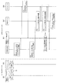
図9は、実施形態の一例としての情報処理システム1におけるローカルサイト10被災時のサイト切替処理の概要を示す図である。
ステップS1において、ローカルサイト10が被災する。
ステップS2において、情報処理システム1の運用管理者が、リモートサイト20の管理サーバ301′(図3参照)上で、WebGUI又はCLIを用いて仮想化ストレージ装置200のリモートコピーのスケジュール停止を指示する。
FIG. 9 is a diagram illustrating an outline of the site switching process when the
In step S1, the
In step S <b> 2, the operation manager of the
ステップS3において、リモートサイト20の仮想化ストレージ装置200のリモートコピーのスケジュールが停止される。
ステップS4において、運用管理者は、リモートサイト20において、仮想化ストレージ装置200のVDISK400をデータストアとして登録するように指示する。
ステップS5において、業務サーバ302′によって、仮想化ストレージ装置200のVDISK400が検出される。
In step S3, the remote copy schedule of the
In step S4, the operation manager instructs the
In step S5, the
ステップS6において、ストレージ制御部124の識別子偽装部313によって、後述するように、S−VDISK400のNAAが、P−VDISK400のNAAと同一の値に書き換えられる(偽装される)。これにより、サイト切替簡略化設定を用いたVDISK400の再署名処理がスキップされる。
ステップS8において、セカンダリサイト20が新たなプライマリサイトとなり、そのVDISK400を使用して業務サーバによる業務が再開される。
In step S6, the
In step S8, the
以下、図10〜図11を用いて、上記の処理について詳細に説明する。
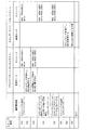
図10は、実施形態の一例としての仮想化ストレージ装置100,200間でのリモートコピー処理を示す図であり、図11は、実施形態の一例としての仮想化ストレージ装置20に対する、識別子を偽装したVDISK400の追加処理を示す図である。図10の処理は、図9に示したローカルサイト10の被災後に実行され、図11の処理は、図9に示すローカルサイト10の被災前に実行される。又、図12は、図10,図11の処理を表形式にまとめた図である。
Hereinafter, the above processing will be described in detail with reference to FIGS.
FIG. 10 is a diagram illustrating remote copy processing between the
まず、図10,図12を用いて、図9に示すローカルサイト10の被災前の処理について説明する。
ステップS11において、運用管理者がプライマリサイト10の管理サーバ301上で、WebGUI又はCLIを用いてP−VDISK400の追加を指示する。
次に、ステップS12において、切替簡易化部320の識別子取得部324が、プライマリサイト10の業務サーバ302に、仮想化ストレージ装置100に対してSCSIコマンドを発行して、P−VDISK400のNAAを取得させる。図10の例では、識別子受信部312により、P−VDISK400のNAAとして、値“e00dc001…”が取得される。
First, processing before the disaster at the
In step S11, the operation manager instructs the addition of the P-
Next, in step S12, the
ステップS13において、meta情報設定部325が、業務サーバ302に、ステップS12で取得したP−VDISK400のNAAを、P−VDISK400のmeta情報に書き込ませる。図10に示す例では、識別子偽装部313は、P−VDISK400のmeta情報に、値“e00dc001…”を書き込み、これによりESXiデータストアにP−VDISK400が追加される。ステップS13でVDISK400の追加が完了すると、当該P−VDISK400は、データストアとして登録され、業務サーバ302で実行中のESXiによって利用可能となる。
In step S13, the meta
その後、ステップS14において、情報処理システム1の運用管理者が、ステップS11でプライマリサイト10に追加したP−VDISK400の識別子の偽装を指示する。このとき、運用管理者は、プライマリサイト10の管理サーバ301を使用して、リモートコピーのスケジュールの作成又は変更を行なうことにより、識別子の偽装を指示する。
ステップS15において、ストレージ制御部124の識別子受信部312が、プライマリサイト10のP−VDISK400のNAAを受信する。そして、識別子偽装部313が、セカンダリサイト20のS−VDISK400のNAAに、プライマリサイト10のP−VDISK400のNAAを設定する。又、識別子偽装部313は、偽装テーブル720(図8参照)にある、S−VDISK400の対応する偽装識別子格納域722に、識別子受信部312が受信したP−VDISK400のNAAの値を書き込む。図10の例では、偽装テーブル720にある、S−VDISK400の対応する偽装識別子格納域722に、P−VDISK400のNAAの値“e00dc001…”が書き込まれる。
Thereafter, in step S14, the operation manager of the
In step S <b> 15, the
ステップS16において、リモートコピー実行部315が、P−VDISK400のデータを、S−VDISK400にコピーする。
次に、図11,図12を用いて、図9に示すローカルサイト10の被災後の処理について説明する。
ステップS21において、運用管理者がセカンダリサイト20の管理サーバ301′上で、WebGUI又はCLIを用いて、P−VDISK400のデータが事前にコピーされているS−VDISK400の追加を指示する。
In step S <b> 16, the remote
Next, processing after the disaster of the
In step S21, the operation manager uses the Web GUI or CLI on the management server 301 'of the
次に、ステップS22において、セカンダリサイト20の業務サーバ302′が、仮想化ストレージ装置200に対してSCSIコマンド(NAA通知要求)を発行して、S−VDISK400のNAAを問い合わせる。NAA通知要求を受けたセカンダリサイト20のストレージ制御装置124の識別子通知部314は、S−VDISK400のNAAを取得して、これを業務サーバ302′に通知する。図11の例では、識別子通知部314により、S−VDISK400のNAAとして、偽装された値“e00dc001…”が取得される。
Next, in step S22, the
ステップS23において、セカンダリサイト20の業務サーバ302′が、ステップS22で取得したNAAとmeta情報とを比較し、両者が一致すると判定し(再署名処理がスキップされる)、S−VDISK400がセカンダリサイト20に追加される。S−VDISK400の追加が完了すると、当該S−VDISK400が、ESXiデータストアとして登録され、業務サーバ302′で実行中のESXiによって利用可能となる。
In step S23, the business server 302 'of the
図13は、実施形態の一例としてのセカンダリサイト20の仮想化ストレージ装置20における識別子の偽装の遷移を模式的に示す図である。
この図は、セカンダリサイト20のS−VDISK400の状態の遷移を示している。ここで、プライマリサイト10のP−VDISK400のNAAを“AAA”、セカンダリサイト20のS−VDISK400のNAAを“BBB”とする。
FIG. 13 is a diagram schematically illustrating a transition of identifier disguise in the
This figure shows the state transition of the S-
状態ST1は、S−VDISK400が作成されていない状態又はS−VDISK400が削除された状態である。
状態ST1のときにS−VDISK400が作成されると、状態ST2に遷移し(矢印A1参照)、識別子偽装テーブル720に、作成したVDISK400のエントリが作成される。
The state ST1 is a state where the S-
When the S-
状態ST2で、簡易化オプションをoff(無効)に指定してのスケジュール作成、簡易化オプションをon(有効)に指定してのスケジュール変更、スケジュール削除、OS再起動、又はパス切替が実行されると、識別子偽装テーブル720の値が変更される。これらの操作では、矢印A3に示すように、状態遷移は発生しない。
なお、本実施形態の一例としての仮想化ストレージ装置100,200においては、リモートコピーのスケジュールの作成、変更、又は削除の際に、簡易化オプションを指定することで、前述のサイト切替簡易化機能の有効/無効を切り替えることができる。サイト切替簡易化機能を有効にするには、簡易化オプションに値onを、サイト切替簡易化機能を無効にするには、簡易化オプションに値offを、それぞれ指定する。
In state ST2, schedule creation with the simplification option set to off (invalid), schedule change, schedule deletion, OS restart, or path switching with the simplification option specified to on (valid) are executed. Then, the value of the identifier disguise table 720 is changed. In these operations, no state transition occurs as indicated by the arrow A3.
In the
一方、状態ST2で、簡易化オプションをonに指定してスケジュールの作成が実行されるか、或いは、簡易化オプションをonに指定してスケジュールの変更が実行されると、S−VDISK400の状態がST3に遷移する。識別子偽装テーブル720の値が変更される(矢印A4参照)。このとき、P−VDISK400のNAAがS−VDISK400に渡されて、S−VDISK400に保持される。
On the other hand, when the schedule creation is executed with the simplification option set to on in the state ST2, or the schedule change is executed with the simplification option set to on, the status of the S-
又、状態ST2のときにS−VDISK400を削除すると、S−VDISK400の状態がST2からST1に遷移する(矢印A2参照)。
状態ST3において、S−VDISK400にINQUIRYコマンドを発行してS−VDISK400のNAAを取得しても、S−VDISK400本来のNAAが取得される。このため、情報処理システム1内に、同じNAAを返すVDISK400が複数存在することはない。
If the S-
Even if the INQUIRY command is issued to the S-
状態ST3で、簡易化オプションをonに指定してのスケジュール作成、OS再起動、又はパス切替が実行されると、識別子偽装テーブル720の値が変更されるが、状態遷移は発生しない(矢印A6参照)。
この状態ST3では、プライマリサイト10のP−VDISK400から、セカンダリサイト20のS−VDISK400へのリモートコピーが実行される。
When schedule creation, OS restart, or path switching is executed with the simplification option set to on in state ST3, the value of the identifier disguise table 720 is changed, but no state transition occurs (arrow A6). reference).
In this state ST3, remote copy from the P-
状態ST3で、簡易化オプションをoffに指定してスケジュールの変更が実行されると、識別子偽装テーブル720の値が変更されると共に、S−VDISK400の状態がST2に戻る(矢印A5参照)。
又、状態ST3のときにS−VDISK400を削除すると、S−VDISK400の状態がST3からST1に遷移する(矢印A7参照)。
When the schedule change is executed with the simplification option set to off in the state ST3, the value of the identifier disguise table 720 is changed and the state of the S-
If S-
さらに、状態ST3のときに、プライマリサイト10が被災すると、運用管理者が、GUI又はCLIを用いて、簡易化オプションをonに指定してリモートコピーのスケジュールを削除する。これにより、S−VDISK400の状態がST4に遷移し(矢印A8参照)、S−VDISK400に保持されていたNAAがtgtd615(図16,図17参照)の不図示のメモリ上に展開される。
Furthermore, when the
状態ST4で、OS再起動又はパス切替が実行されると、識別子偽装テーブル720の値が変更されるが、状態遷移は発生しない(矢印A9参照)。
又、状態ST4のときにS−VDISK400を削除すると、S−VDISK400の状態がST4からST1に遷移する(矢印A10参照)。
図14,図15は、実施形態の一例としての仮想化ストレージ装置100,200におけるリモートコピーのスケジュール作成又は変更処理をモジュール単位で示す図である。
When OS restart or path switching is executed in state ST4, the value of the identifier disguise table 720 is changed, but no state transition occurs (see arrow A9).
If the S-
FIGS. 14 and 15 are diagrams illustrating remote copy schedule creation or change processing in the
スケジュールの作成及び変更はプライマリサイト10側からのみ実行可能であり、スケジュールの作成及び変更をセカンダリサイト20側から行なうことはできない。
図14,図15において、GUI602,611は、GUIを実現するためのモジュールである。
又、基盤CLI603,612は、それぞれ、後述するSVE−M604,613の構成管理や構成情報取得を行なうコマンドである。
The creation and modification of the schedule can be executed only from the
14 and 15,
The
SVE−M604,613は、クラスタ制御部703−1が存在するPU11(図)5の例ではPU11−1)で動作し、ストレージ仮想化を提供するエンジンであるSVEの構成を管理、制御するデーモンプログラムである。SVE−M604,613は、図5のボリューム管理マネージャ707に相当する。なお、SVEは、Storage Virtualization Engineの略語である。
The SVE-
ステップS31において、運用管理者が、プライマリサイト10側でCLIを用いて、create rc−scheduleコマンド又はmodify rc−scheduleコマンドを実行して、リモートコピーのスケジュールを作成又は変更する。その際、運用管理者は、create rc−scheduleコマンド又はmodify rc−scheduleコマンドのパラメータとして、前述のサイト切替簡易化オプションを指定する。
In step S31, the operation manager uses the CLI on the
或いは、運用管理者が、WebGUIを用いてリモートコピーのスケジュールを作成又は変更してもよい。
ステップS32において、GUI602が、プライマリサイト10側のスケジュールの作成又は変更処理を実行する。
詳細には、ステップS33において、GUI602は、GUI602の不図示のデータベースに、ステップS31で作成又は変更されたスケジュールの情報を、サイト切替簡易化オプションと共に保存する。
Alternatively, the operation manager may create or change a remote copy schedule using WebGUI.
In step S32, the
Specifically, in step S33, the
ステップS31で作成又は変更されたスケジュールのサイト切替簡易化オプションがtrue(有効)である場合、ステップS34において、GUI602は、新規基盤コマンドのnaa取得コマンドを実行する。
ステップS35において、基盤CLI603は、naa取得コマンドを実行する。
ステップS36において、SVE−M604がnaaを取得し、取得したnaaが、基盤CLI603を介してGUI602に返される。
When the site switching simplification option of the schedule created or changed in step S31 is true (valid), in step S34, the
In step S35, the
In step S36, the SVE-
次にステップS37において、GUI602は、リモートサイト20側のGUI611に、ステップS31で作成又は変更されたスケジュールの情報を、サイト切替簡易化オプション及びnaaと共に送信する。
ステップS38において、GUI611が、セカンダリサイト20側のスケジュールの作成又は変更処理を実行する。
In step S37, the
In step S38, the
詳細には、ステップS39において、GUI611は、GUI611の不図示のデータベースに、スケジュールの情報を、サイト切替簡易化オプションと共に保存する。
ステップS40において、スケジュールのサイト切替簡易化オプションがtrue(有効)で、naaが設定されている場合、GUI611は、スケジュール設定コマンドを実行すると共にNAA有効フラグをfalseに設定する。
Specifically, in step S39, the
In step S40, when the schedule site switching simplification option is true (valid) and naa is set, the
ステップS41において、基盤CLI612が、naa取得コマンドを実行する。
ステップS42において、SVE−M613がnaaを設定すると共に、NAA有効フラグをfalseに設定する。
一方、スケジュールのサイト切替簡易化オプションがfalse(無効)の場合、ステップS43において、GUI611は、スケジュール削除コマンドを実行する。
In step S41, the
In step S42, the SVE-
On the other hand, if the schedule site switching simplification option is false (invalid), the
ステップS44において、基盤CLI612は、naa削除コマンドを実行する。
ステップS42において、SVE−M613はnaaを削除すると共に、NAA有効フラグをfalseに設定する。
図16は、実施形態の一例としての仮想化ストレージ装置100,200におけるリモートコピーのスケジュール削除処理をモジュール単位で示す図である。
In step S44, the
In step S42, the SVE-
FIG. 16 is a diagram illustrating remote copy schedule deletion processing in the
NAAの内容は、VX固有のシリアル番号、作成ボリューム固有のボリューム番号を含み、本来ボリューム毎に一意である。このため、サイト切替え手順簡易化設定を有効にした場合、スケジュールを削除した時点で、プライマリサイト10、セカンダリサイト20で同時に同一のNAAを持つボリュームが存在することになる。
本来一意となるべき同一のNAAを持つボリュームが同時にプライマリサイト10、セカンダリサイト20に存在することを防ぐため、スケジュール削除のタイミングで、プライマリサイト10のボリュームの削除を行なう。
The contents of the NAA include a serial number unique to VX and a volume number unique to the created volume, and are inherently unique for each volume. Therefore, when the site switching procedure simplification setting is enabled, when the schedule is deleted, volumes having the same NAA exist at the
In order to prevent a volume having the same NAA that should be unique from being present at the
図16において、tgtd615は、iSCSIターゲット情報を管理しているデーモンである。tgtd615については公知であるため、その説明を省略する。
ステップS51において、運用管理者が、プライマリサイト10側でCLIを用いて、delete rc−scheduleコマンドを実行して、リモートコピーのスケジュールを削除する。
In FIG. 16,
In step S51, the operation manager executes a delete rc-schedule command on the
或いは、運用管理者が、WebGUIを用いてリモートコピーのスケジュールを削除してもよい。
ステップS52において、GUI602が、プライマリサイト10側のスケジュールの削除処理を実行する。
詳細には、ステップS53において、GUI602は、セカンダリサイト20側のGUI611に、スケジュール削除依頼情報を送信する。
Alternatively, the operation manager may delete the remote copy schedule using the Web GUI.
In step S52, the
Specifically, in step S53, the
ステップS54において、GUI611は、スケジュールを削除する。
詳細には、ステップS55において、GUI611は、naaをtgtd615(図16,図17参照)の不図示のメモリ上に展開させる。
ステップS56において、基盤CLI612が、naaをtgtd615のメモリ上に展開する。
In step S54, the
Specifically, in step S55, the
In step S56, the
ステップS57において、tgtd615が、取得したnaaをメモリ上に展開する。
次にステップS58において、GUI611は、GUI611の不図示のデータベースから、スケジュールの情報を、サイト切替簡易化オプションと共に削除する。
ステップS59において、プライマリサイト側のGUI602は、GUI602の不図示のデータベースから、スケジュールの情報を、サイト切替簡易化オプションと共に削除する。
In step S57, the
In step S58, the
In step S59, the
なお、スケジュールの削除は、セカンダリサイト20からも実行可能である。運用管理者がセカンダリサイト20からスケジュールの削除を実行した場合、上記のステップS54以降のセカンダリサイト20側での処理のみが実行される。
図17は、実施形態の一例としての仮想化ストレージ装置100,200におけるOS起動時のリカバリ処理をモジュール単位で示す図である。
The deletion of the schedule can also be executed from the
FIG. 17 is a diagram illustrating recovery processing at the time of OS startup in the
ここで、SVE−A614は、全PU11で動作し、ドライバの制御及びエラーなどのイベントをモニタするデーモンプログラムである。SVE−A614は、図5のボリューム管理エージェント709−1〜709−3に相当する。
この処理は、スケールアウトやパス切替えや、PU13の再起動時に、tgtd615のメモリ上のNAA情報を復元する。
Here, the SVE-
This process restores the NAA information in the memory of
仮想化ストレージ装置200のOS起動時に、再起動前の状態に復元されるため、故障リカバリ処理を行なう。このリカバリ処理の際に、tgtd615のメモリ上のNAA情報が復元される。
仮想化ストレージ装置200が再起動され、PU13が再起動され、リカバリ処理が実行される。その際、ステップS61において、ターゲット作成処理が実行される。ターゲット作成処理とは、ボリュームの接続情報をPU11内のメモリ502上に展開することを指す。
Since the
The
詳細には、セカンダリサイト20側のSVE−M613が、各ターゲットのnaa及びNAA有効フラグを取得する。各ターゲットとは、再起動されたPU11内に、再起動前から作成されていたボリュームの接続情報のことを指す。また、NAA有効フラグとは、対象ボリュームの偽装NAAが、tgtdのメモリ上に展開しているかを示すフラグを指す。
Specifically, the SVE-
ターゲットのnaaが設定されており、かつNAA有効フラグが設定されている場合、SVE−M613は、取得したnaaをtgtdのメモリ上に展開させる。
ステップS62において、SVE−A614が、ivsmtgtctlを実行して、naaをtgtdのメモリ上に展開する。ここで、ivsmtgtctlとは、SVE−Aから渡されたパラメータを解析して、tgtd615へターゲット操作の依頼をするコマンドである。
When the target naa is set and the NAA valid flag is set, the SVE-
In step S62, the SVE-
ステップS63において、tgtd615が、取得したnaaをメモリ上に展開する。
次に、ストレージ制御部124の動作について説明する。
図18は、実施形態の一例としてのセカンダリサイト20のストレージ制御部124の処理を示すフローチャート(ステップS71〜S77)である。
ステップS71において、セカンダリサイト20のストレージ制御部124の識別子受信部312が、プライマリサイト10のコピー元VDISK400のNAAを受信する。
In step S63, the
Next, the operation of the
FIG. 18 is a flowchart (steps S71 to S77) illustrating processing of the
In step S71, the
ステップS72において、識別子受信部312は、ステップS71で受信したコピー元VDISK400のNAAを識別子偽装テーブル720に格納する。
ステップS73において、識別子偽装部313は、リモートコピーのスケジュールの追加又は変更等のコマンドを使用して、ステップS71で受信したS−VDISK400のNAAを、P−VDISK400のNAAの値に書き換える。
In step S72, the
In step S <b> 73, the
その後、ステップS74において、ストレージ制御部124は、業務サーバ302,302′からSCSIコマンドの受信を待機し、SCSIコマンドを受信する。
ステップS75において、ストレージ制御部124は、ステップS74で受信したSCSIコマンドが、NAA通知要求であるかどうかを判定する。ここで、NAA通知要求とは、コピー先VDISK400のNAAを問い合わせるために、業務サーバ302,302が使用するSCSIコマンドである。
Thereafter, in step S74, the
In step S75, the
ステップS74で受信したSCSIコマンドがNAA通知要求である場合(ステップS75のYESルート参照)、ステップS76において、識別子通知部315が、図19を用いて後述する識別子通知処理を実行する。その後、処理がS74に戻る。
一方、ステップS74で受信したSCSIコマンドがNAA通知要求以外のSCSIコマンドである場合(ステップS75のNOルート参照)、ステップS77において、ストレージ制御部124は、SCSIコマンドの内容に応じて、該SCSIコマンドを適宜処理する。
If the SCSI command received in step S74 is a NAA notification request (see YES route in step S75), in step S76, the
On the other hand, when the SCSI command received in step S74 is a SCSI command other than the NAA notification request (see NO route in step S75), in step S77, the
図19は、実施形態の一例としての識別子通知部314による識別子通知処理を示すフローチャート(ステップS81〜S84)である。
ステップS81において、識別子通知部314は、識別子偽装テーブル720から、コピー先VDISK400の偽装フラグ723の値を取得する。
ステップS82において、識別子通知部314は、ステップS81で取得した偽装フラグ723の値に基づいて、コピー先VDISK400に対して識別子偽装が行なわれているかどうかを判定する。例えば、ステップS81で取得した偽装フラグ723の値がtrueの場合、識別子通知部314は、コピー先VDISK400に対して識別子偽装が行なわれていると判定する。
FIG. 19 is a flowchart (steps S81 to S84) illustrating an identifier notification process by the
In step S <b> 81, the
In step S <b> 82, the
コピー先VDISK400に対して識別子偽装が行なわれてない場合(ステップS82のNOルート参照)、ステップS83において、識別子通知部315は、コピー先VDISK400の本来のNAAである、識別子偽装テーブル720の識別子格納域721の値を、業務サーバ302,302′に通知する。例えば、コピー先VDISK400が図13の状態ST2の場合には、識別子通知部315は、“AAA”を、コピー先VDISK400のNAAとして業務サーバ302,302′に通知する。つまり、識別子偽装が行なわれていない場合には、識別子通知部314は、コピー先VDISK400の元の(偽装されていない)NAAを、業務サーバ302,302′に通知する。
When identifier impersonation is not performed for the copy destination VDISK 400 (see NO route in step S82), in step S83, the
その後、識別子通知処理を終了し、処理が図18のステップS74に戻る。
一方、コピー先VDISK400に対して識別子偽装が行なわれている場合(ステップS82のYESルート参照)、ステップS84において、識別子通知部315は、識別子偽装テーブル720の偽装識別子格納域722の値を、コピー先VDISK400のNAAとして業務サーバ302,302′に通知する。例えば、図13の状態ST4の場合には、識別子通知部315は、“BBB”を、コピー先VDISK400のNAAとして業務サーバ302,302′に通知する。つまり、識別子偽装が行なわれている場合には、識別子通知部314は、識別子偽装部313によって偽装されたNAAを、業務サーバ302,302′に通知する。
Thereafter, the identifier notification process is terminated, and the process returns to step S74 of FIG.
On the other hand, when identifier forgery is performed for the copy destination VDISK 400 (see YES route in step S82), in step S84, the
その後、識別子通知処理を終了し、処理が図18のステップS74に戻る。
(C)効果
このように、本実施形態の一例の仮想化ストレージ装置100,200によれば、セカンダリサイト20のS−VDISK400のNAAを、プライマリサイト10のP−VDISK400のNAAと同じ値に設定する。これにより、時間のかかるスケールアウト型仮想化ストレージ装置200のS−VDISK400の再署名(再登録)処理を省略(スキップ)することができる。これにより、仮想化ストレージ装置100の被災時等に、仮想化ストレージ装置200へのサイト切替時間が短縮される。
Thereafter, the identifier notification process is terminated, and the process returns to step S74 of FIG.
(C) Effect As described above, according to the
又、プライマリサイト10のP−VDISK400からセカンダリサイト20のS−VDISK400へのデータのリモートコピーを、簡易化オプションを指定したリモートコピーのスケジュールを作成又は変更することにより実行する。これにより、リモートコピーのための新たなコマンドの追加が不要となる。さらに、リモートコピーのスケジュールの変更により、サイト切替簡易化機能の有効/無効を切り替えることができる。
(D)その他
なお、上述した実施形態に関わらず、本実施形態の趣旨を逸脱しない範囲で種々変形して実施することができる。
Further, remote copy of data from the P-
(D) Others Regardless of the embodiment described above, various modifications can be made without departing from the spirit of the present embodiment.
例えば、上記の実施形態の一例においては、SU13に2台のPU11が接続されていたが、各SU13に1台又は3台以上のPU11が接続されてもよい。
又、上記の実施形態の一例においては、プライマリサイト10、セカンダリサイト20の双方に、管理サーバ301,301′及び業務サーバ302,302′をそれぞれ設置している。しかし、ストレージ装置100のリプレースの場合など、プライマリサイト10のみに管理サーバ301及び業務サーバ302を設置してもよい。
For example, in the example of the above embodiment, two
In the example of the above embodiment,
或いは、上記の実施形態の一例においては、仮想化環境としてVMWare ESXiを例に採り上げたが、他の仮想化環境を使用してもよい。
又、上記の実施形態の一例では、図18のステップS73において、識別子偽装部313が、リモートコピーのスケジュールの追加又は変更等のコマンドを使用して、S−VDISK400のNAAをP−VDISK400のNAAの値に書き換えている。しかし、これに限定されるものではなく、NAAの書き換えに他の既存コマンドが使用されてもよい。或いは、識別子偽装部313が、新たに設けたNAAの設定用のコマンドを受けたときに、識別子の偽装を行なってもよい。
Alternatively, in the example of the above-described embodiment, the VMWare ESXi is taken as an example of the virtualization environment, but other virtualization environments may be used.
In the example of the above embodiment, in step S73 of FIG. 18, the
(E)付記
以上の実施形態に関し、さらに以下の付記を開示する。
(付記1)
第1の仮想化ストレージ装置の第1のボリュームのコピー先である第2の仮想化ストレージ装置の第2のボリュームの制御を行なうストレージ制御装置であって、
前記第1の仮想化ストレージ装置から受信した前記第1のボリュームの第1の識別子を格納する識別子格納部と、
前記識別子格納部に格納された前記第1の識別子を、前記第2のボリュームの第2の識別子として設定する設定部と、
前記第2の識別子の通知要求に応じて、前記設定部により設定された第1の識別子を通知する識別子通知部と、
をそなえることを特徴とするストレージ制御装置。
(E) Additional remarks The following additional remarks are disclosed regarding the above embodiment.
(Appendix 1)
A storage control device that controls a second volume of a second virtualization storage device that is a copy destination of the first volume of the first virtualization storage device,
An identifier storage unit for storing a first identifier of the first volume received from the first virtualization storage device;
A setting unit configured to set the first identifier stored in the identifier storage unit as a second identifier of the second volume;
An identifier notifying unit for notifying the first identifier set by the setting unit in response to the notification request for the second identifier;
A storage control device characterized by comprising:
(付記2)
前記第2の仮想化ストレージ装置は、ボリュームを追加設定可能なストレージ装置であり、
前記ストレージ制御装置は、前記第2の仮想化ストレージ装置にボリュームを追加するボリューム追加部をさらにそなえ、
前記設定部は、追加された各ボリュームの識別子に対して、対応するコピー元のボリュームの識別子を設定する
ことを特徴とする付記1記載のストレージ制御装置。
(Appendix 2)
The second virtualization storage device is a storage device that can additionally set a volume,
The storage control device further comprises a volume addition unit for adding a volume to the second virtualization storage device,
The storage control apparatus according to
(付記3)
前記設定部は、リモートコピースケジュールの作成又は変更指示を受信すると、前記第1の識別子を前記第2の仮想化ストレージ装置の第2のボリュームの識別子に設定することにより、前記第2の仮想化ストレージ装置への前記第2のボリュームの再登録をスキップさせる
ことを特徴とする付記1又は2記載のストレージ制御装置。
(Appendix 3)
When the setting unit receives an instruction to create or change a remote copy schedule, the setting unit sets the first identifier to the identifier of the second volume of the second virtualization storage device, whereby the second virtualization The storage control apparatus according to
(付記4)
第1の仮想化ストレージ装置の第1のボリュームのコピー先である第2の仮想化ストレージ装置の第2のボリュームの制御を行なうストレージ制御方法であって、
前記第1の仮想化ストレージ装置から受信した前記第1のボリュームの第1の識別子を識別子格納部に格納し、
前記識別子格納部に格納された前記第1の識別子を、前記第2のボリュームの第2の識別子として設定し、
前記第2の識別子の通知要求に応じて、前記第2のボリュームの第2の識別子として設定された前記第1の識別子を通知する
ことを特徴とするストレージ制御方法。
(Appendix 4)
A storage control method for controlling a second volume of a second virtualization storage device that is a copy destination of a first volume of a first virtualization storage device,
Storing the first identifier of the first volume received from the first virtualization storage device in an identifier storage unit;
Setting the first identifier stored in the identifier storage unit as a second identifier of the second volume;
The storage control method, wherein the first identifier set as the second identifier of the second volume is notified in response to the notification request for the second identifier.
(付記5)
前記第2の仮想化ストレージ装置は、ボリュームを追加設定可能なストレージ装置であり、
ストレージ制御方法は、さらに、前記第2の仮想化ストレージ装置にボリュームを追加し、
前記追加された各ボリュームの識別子に対して、対応するコピー元のボリュームの識別子を設定する
ことを特徴とする付記4記載のストレージ制御方法。
(Appendix 5)
The second virtualization storage device is a storage device that can additionally set a volume,
The storage control method further includes adding a volume to the second virtualization storage device,
The storage control method according to
(付記6)
リモートコピースケジュールの作成又は変更指示を受信すると、前記第1の識別子を前記第2の仮想化ストレージ装置の第2のボリュームの識別子に設定することにより、前記第2の仮想化ストレージ装置への前記第2のボリュームの再登録をスキップさせる
ことを特徴とする付記4又は5記載のストレージ制御方法。
(Appendix 6)
When receiving an instruction to create or change a remote copy schedule, the first identifier is set to the identifier of the second volume of the second virtualization storage device, so that the second virtualization storage device The storage control method according to
(付記7)
第1の仮想化ストレージ装置の第1のボリュームのコピー先である第2の仮想化ストレージ装置の第2のボリュームの制御を行なうストレージ制御プログラムであって、
前記第1の仮想化ストレージ装置から受信した前記第1のボリュームの第1の識別子を識別子格納部に格納し、
前記識別子格納部に格納された前記第1の識別子を、前記第2のボリュームの第2の識別子として設定し、
前記第2の識別子の通知要求に応じて、前記第2のボリュームの第2の識別子として設定された前記第1の識別子を通知する
処理をコンピュータに実行させることを特徴とするストレージ制御プログラム。
(Appendix 7)
A storage control program for controlling a second volume of a second virtualization storage device that is a copy destination of a first volume of a first virtualization storage device,
Storing the first identifier of the first volume received from the first virtualization storage device in an identifier storage unit;
Setting the first identifier stored in the identifier storage unit as a second identifier of the second volume;
A storage control program that causes a computer to execute a process of notifying the first identifier set as the second identifier of the second volume in response to the notification request for the second identifier.
(付記8)
前記第2の仮想化ストレージ装置はボリュームを追加可能なストレージ装置であり、
前記ストレージ制御プログラムは、前記第2の仮想化ストレージ装置にボリュームを追加する
処理を前記コンピュータに実行させることを特徴とする付記7記載のストレージ制御プログラム。
(Appendix 8)
The second virtualization storage device is a storage device to which a volume can be added,
The storage control program according to
(付記9)
リモートコピースケジュールの作成又は変更指示を受信すると、前記第1の識別子を前記第2の仮想化ストレージ装置の第2のボリュームの識別子に設定することにより、前記第2の仮想化ストレージ装置への前記第2のボリュームの再登録をスキップさせる
処理を前記コンピュータに実行させることを特徴とする付記7又は8記載のストレージ制御プログラム。
(Appendix 9)
When receiving an instruction to create or change a remote copy schedule, the first identifier is set to the identifier of the second volume of the second virtualization storage device, so that the second virtualization storage device The storage control program according to
(付記10)
第1のボリュームを有する第1の仮想化ストレージ装置と、
第2のボリュームを有する第2の仮想化ストレージ装置と、をそなえ、
前記第1の仮想化ストレージ装置は、
前記第1の仮想化ストレージ装置から受信した前記第1のボリュームの第1の識別子を格納する識別子格納部と、
前記識別子格納部に格納された前記第1の識別子を、前記第2のボリュームの第2の識別子として設定する設定部と、
前記第2の識別子の通知要求に応じて、前記設定部により設定された第1の識別子を通知する識別子通知部と、
をそなえることを特徴とするストレージシステム。
(Appendix 10)
A first virtualization storage device having a first volume;
A second virtual storage device having a second volume,
The first virtualization storage device is:
An identifier storage unit for storing a first identifier of the first volume received from the first virtualization storage device;
A setting unit configured to set the first identifier stored in the identifier storage unit as a second identifier of the second volume;
An identifier notifying unit for notifying the first identifier set by the setting unit in response to the notification request for the second identifier;
A storage system characterized by having
(付記11)
前記第2の仮想化ストレージ装置は、ボリュームを追加設定可能なストレージ装置であり、
前記第1の仮想化ストレージ装置は、前記第2の仮想化ストレージ装置にボリュームを追加するボリューム追加部をさらにそなえ、
前記設定部は、追加された各ボリュームの識別子に対して、対応するコピー元のボリュームの識別子を設定する
ことを特徴とする付記10記載のストレージシステム。
(Appendix 11)
The second virtualization storage device is a storage device that can additionally set a volume,
The first virtualization storage device further comprises a volume addition unit for adding a volume to the second virtualization storage device,
The storage system according to
(付記12)
前記設定部は、リモートコピースケジュールの作成又は変更指示を受信すると、前記第1の識別子を前記第2の仮想化ストレージ装置の第2のボリュームの識別子に設定することにより、前記第2の仮想化ストレージ装置への前記第2のボリュームの再登録をスキップさせる
ことを特徴とする付記10又は11記載のストレージシステム。
(Appendix 12)
When the setting unit receives an instruction to create or change a remote copy schedule, the setting unit sets the first identifier to the identifier of the second volume of the second virtualization storage device, whereby the second virtualization The storage system according to
1 情報処理システム(ストレージシステム)
11,11′,11″ PU
12,12′,12″ スイッチ
13,13′,13″ SU
100 仮想化ストレージ装置(第1の仮想化ストレージ装置)
200 仮想化ストレージ装置(第2の仮想化ストレージ装置)
114,124 記憶部
301,301′ 管理サーバ
302,302′ 業務サーバ
311 ボリューム追加/削除部(ボリューム追加部)
312 識別子受信部(受信部)
313 識別子偽装部(設定部)
314 識別子通知部
315 リモートコピー実行部(複製部)
320 切替容易化部
321 受付部
322 オプション判定部
323 スケジュール追加/変更/削除部
324 識別子取得部
325 meta情報設定部
400 VDISK(第1及び第2のボリューム)
501 CPU
502 メモリ(識別子格納部)
1 Information processing system (storage system)
11, 11 ', 11 "PU
12, 12 ', 12 "
100 Virtualization storage device (first virtualization storage device)
200 Virtualization storage device (second virtualization storage device)
114, 124
312 Identifier receiving unit (receiving unit)
313 Identifier disguised part (setting part)
314
320
501 CPU
502 Memory (identifier storage unit)
Claims (4)
前記第1の仮想化ストレージ装置から受信した前記第1のボリュームの第1の識別子を格納する識別子格納部と、
前記第1の仮想化ストレージ装置のデータを前記第2の仮想化ストレージ装置にコピーするリモートコピーのスケジュールの作成又は変更指示を受信すると、前記識別子格納部に格納された前記第1の識別子を、前記第2のボリュームの第2の識別子として設定することにより、前記第2のボリュームを前記第2の仮想化ストレージ装置のデータストアとして登録する再登録処理をスキップさせる設定部と、
前記第2の識別子の通知要求に応じて、前記設定部により設定された第1の識別子を通知する識別子通知部と、
をそなえることを特徴とするストレージ制御装置。 A storage control device that controls a second volume of a second virtualization storage device that is a copy destination of the first volume of the first virtualization storage device,
An identifier storage unit for storing a first identifier of the first volume received from the first virtualization storage device;
When receiving a remote copy schedule creation or change instruction for copying data of the first virtualization storage device to the second virtualization storage device, the first identifier stored in the identifier storage unit is changed to: A setting unit for skipping a re-registration process for registering the second volume as a data store of the second virtualization storage device by setting the second identifier as the second identifier of the second volume ;
An identifier notifying unit for notifying the first identifier set by the setting unit in response to the notification request for the second identifier;
A storage control device characterized by comprising:
前記ストレージ制御装置は、前記第2の仮想化ストレージ装置にボリュームを追加するボリューム追加部をさらにそなえ、
前記設定部は、追加された各ボリュームの識別子に対して、対応するコピー元のボリュームの識別子を設定する
ことを特徴とする請求項1記載のストレージ制御装置。 The second virtualization storage device is a storage device that can additionally set a volume,
The storage control device further comprises a volume addition unit for adding a volume to the second virtualization storage device,
The setting unit, to the identifier of each volume is added, the corresponding storage control equipment according to claim 1, wherein setting the identifier of the copy source volume.
前記第1の仮想化ストレージ装置から受信した前記第1のボリュームの第1の識別子を識別子格納部に格納し、
前記第1の仮想化ストレージ装置のデータを前記第2の仮想化ストレージ装置にコピーするリモートコピーのスケジュールの作成又は変更指示を受信すると、前記識別子格納部に格納された前記第1の識別子を、前記第2のボリュームの第2の識別子として設定することにより、前記第2のボリュームを前記第2の仮想化ストレージ装置のデータストアとして登録する再登録処理をスキップさせ、
前記第2の識別子の通知要求に応じて、前記第2のボリュームの第2の識別子として設定された前記第1の識別子を通知する
ことを特徴とするストレージ制御方法。 A storage control method for controlling a second volume of a second virtualization storage device that is a copy destination of a first volume of a first virtualization storage device,
Storing the first identifier of the first volume received from the first virtualization storage device in an identifier storage unit;
When receiving a remote copy schedule creation or change instruction for copying data of the first virtualization storage device to the second virtualization storage device, the first identifier stored in the identifier storage unit is changed to: By setting as the second identifier of the second volume, the re-registration process for registering the second volume as a data store of the second virtualization storage device is skipped ,
The storage control method, wherein the first identifier set as the second identifier of the second volume is notified in response to the notification request for the second identifier.
前記第1の仮想化ストレージ装置から受信した前記第1のボリュームの第1の識別子を識別子格納部に格納し、
前記第1の仮想化ストレージ装置のデータを前記第2の仮想化ストレージ装置にコピーするリモートコピーのスケジュールの作成又は変更指示を受信すると、前記識別子格納部に格納された前記第1の識別子を、前記第2のボリュームの第2の識別子として設定することにより、前記第2のボリュームを前記第2の仮想化ストレージ装置のデータストアとして登録する再登録処理をスキップさせ、
前記第2の識別子の通知要求に応じて、前記第2のボリュームの第2の識別子として設定された前記第1の識別子を通知する
処理をコンピュータに実行させることを特徴とするストレージ制御プログラム。 A storage control program for controlling a second volume of a second virtualization storage device that is a copy destination of a first volume of a first virtualization storage device,
Storing the first identifier of the first volume received from the first virtualization storage device in an identifier storage unit;
When receiving a remote copy schedule creation or change instruction for copying data of the first virtualization storage device to the second virtualization storage device, the first identifier stored in the identifier storage unit is changed to: By setting as the second identifier of the second volume, the re-registration process for registering the second volume as a data store of the second virtualization storage device is skipped ,
A storage control program that causes a computer to execute a process of notifying the first identifier set as the second identifier of the second volume in response to the notification request for the second identifier.
Priority Applications (3)
| Application Number | Priority Date | Filing Date | Title |
|---|---|---|---|
| JP2013202071A JP6201580B2 (en) | 2013-09-27 | 2013-09-27 | Storage control device, storage control method, and storage control program |
| US14/474,331 US9552172B2 (en) | 2013-09-27 | 2014-09-02 | Storage processing apparatus, computer-readable recording medium storing program for controlling storage, and storage system |
| EP14183352.5A EP2854019A1 (en) | 2013-09-27 | 2014-09-03 | Storage processing apparatus, method of controlling storage, program for controlling storage, and storage system |
Applications Claiming Priority (1)
| Application Number | Priority Date | Filing Date | Title |
|---|---|---|---|
| JP2013202071A JP6201580B2 (en) | 2013-09-27 | 2013-09-27 | Storage control device, storage control method, and storage control program |
Publications (2)
| Publication Number | Publication Date |
|---|---|
| JP2015069342A JP2015069342A (en) | 2015-04-13 |
| JP6201580B2 true JP6201580B2 (en) | 2017-09-27 |
Family
ID=51492837
Family Applications (1)
| Application Number | Title | Priority Date | Filing Date |
|---|---|---|---|
| JP2013202071A Expired - Fee Related JP6201580B2 (en) | 2013-09-27 | 2013-09-27 | Storage control device, storage control method, and storage control program |
Country Status (3)
| Country | Link |
|---|---|
| US (1) | US9552172B2 (en) |
| EP (1) | EP2854019A1 (en) |
| JP (1) | JP6201580B2 (en) |
Families Citing this family (2)
| Publication number | Priority date | Publication date | Assignee | Title |
|---|---|---|---|---|
| US10437497B1 (en) * | 2015-09-30 | 2019-10-08 | EMC IP Holding Company LLC | Active-active host environment |
| US10303362B2 (en) * | 2017-02-15 | 2019-05-28 | Netapp, Inc. | Methods for reducing initialization duration and performance impact during configuration of storage drives |
Family Cites Families (19)
| Publication number | Priority date | Publication date | Assignee | Title |
|---|---|---|---|---|
| US6557089B1 (en) * | 2000-11-28 | 2003-04-29 | International Business Machines Corporation | Backup by ID-suppressed instant virtual copy then physical backup copy with ID reintroduced |
| JP2005338893A (en) | 2004-05-24 | 2005-12-08 | Hitachi Ltd | Data processing system, disk access control method and processing program therefor |
| JP2006309638A (en) * | 2005-05-02 | 2006-11-09 | Hitachi Ltd | Computer system, and host computer and storage device used for the computer system, and volume changeover method used for the computer system |
| JP2008269469A (en) * | 2007-04-24 | 2008-11-06 | Hitachi Ltd | Storage system and management method therefor |
| US8028110B1 (en) | 2007-06-28 | 2011-09-27 | Emc Corporation | Non-disruptive data migration among storage devices using integrated virtualization engine of a storage device |
| JP2009093316A (en) | 2007-10-05 | 2009-04-30 | Hitachi Ltd | Storage system and virtualization method |
| US9619171B2 (en) | 2007-10-05 | 2017-04-11 | Hitachi, Ltd. | Storage system and virtualization method |
| US8060710B1 (en) | 2007-12-12 | 2011-11-15 | Emc Corporation | Non-disruptive migration using device identity spoofing and passive/active ORS pull sessions |
| JP5072692B2 (en) | 2008-04-07 | 2012-11-14 | 株式会社日立製作所 | Storage system with multiple storage system modules |
| WO2010084522A1 (en) * | 2009-01-20 | 2010-07-29 | Hitachi, Ltd. | Storage system and method for controlling the same |
| US8166264B2 (en) * | 2009-02-05 | 2012-04-24 | Hitachi, Ltd. | Method and apparatus for logical volume management |
| US20100235592A1 (en) * | 2009-03-10 | 2010-09-16 | Yasunori Kaneda | Date volume migration with migration log confirmation |
| JP5156682B2 (en) * | 2009-04-23 | 2013-03-06 | 株式会社日立製作所 | Backup method in storage system |
| US9244786B2 (en) * | 2010-12-10 | 2016-01-26 | International Business Machines Corporation | Substitution of a target volume of a secondary storage controller for a source volume of a primary storage controller for executing a write operation |
| US8566635B2 (en) * | 2011-01-21 | 2013-10-22 | Lsi Corporation | Methods and systems for improved storage replication management and service continuance in a computing enterprise |
| US8819374B1 (en) * | 2011-06-15 | 2014-08-26 | Emc Corporation | Techniques for performing data migration |
| US8719497B1 (en) * | 2011-09-21 | 2014-05-06 | Emc Corporation | Using device spoofing to improve recovery time in a continuous data protection environment |
| JP2013114624A (en) * | 2011-11-30 | 2013-06-10 | Hitachi Ltd | Storage system and control method for pool capacity reduction |
| US9098466B2 (en) * | 2012-10-29 | 2015-08-04 | International Business Machines Corporation | Switching between mirrored volumes |
-
2013
- 2013-09-27 JP JP2013202071A patent/JP6201580B2/en not_active Expired - Fee Related
-
2014
- 2014-09-02 US US14/474,331 patent/US9552172B2/en not_active Expired - Fee Related
- 2014-09-03 EP EP14183352.5A patent/EP2854019A1/en not_active Ceased
Also Published As
| Publication number | Publication date |
|---|---|
| EP2854019A1 (en) | 2015-04-01 |
| JP2015069342A (en) | 2015-04-13 |
| US20150095599A1 (en) | 2015-04-02 |
| US9552172B2 (en) | 2017-01-24 |
Similar Documents
| Publication | Publication Date | Title |
|---|---|---|
| WO2018040591A1 (en) | Remote data replication method and system | |
| US8204858B2 (en) | Snapshot reset method and apparatus | |
| US9116913B2 (en) | File storage system and file cloning method | |
| JP7034806B2 (en) | Data path monitoring in a distributed storage network | |
| JP5172574B2 (en) | Management computer used to build a backup configuration for application data | |
| JP2018028715A (en) | Storage control device, storage system, and storage control program | |
| US20190138405A1 (en) | Data Loading Method and Apparatus | |
| US20060271754A1 (en) | Storage system | |
| JP2007206931A (en) | Storage system, data processing method and storage device | |
| JP2013011919A (en) | Storage apparatus and snapshot control method of the same | |
| WO2015162684A1 (en) | Data migration method of storage system | |
| JP5352490B2 (en) | Server image capacity optimization | |
| US11579983B2 (en) | Snapshot performance optimizations | |
| US20190034092A1 (en) | Methods for managing distributed snapshot for low latency storage and devices thereof | |
| US10031682B1 (en) | Methods for improved data store migrations and devices thereof | |
| JP2014044553A (en) | Program, information processing device, and information processing system | |
| CN109407975B (en) | Data writing method, computing node and distributed storage system | |
| US11816359B2 (en) | Scalable solid-state storage system and methods thereof | |
| JP6201580B2 (en) | Storage control device, storage control method, and storage control program | |
| US10956271B2 (en) | Point-in-time copy on a remote system | |
| EP3647953B1 (en) | System and method for data backup in mixed disk environment | |
| JP2013161383A (en) | Information processing device, information processing method, program and information processing system | |
| US20070124366A1 (en) | Storage control method for managing access environment enabling host to access data | |
| JP2015207277A (en) | Storage system data migration method | |
| CN114341792B (en) | Data partition switching between storage clusters |
Legal Events
| Date | Code | Title | Description |
|---|---|---|---|
| A621 | Written request for application examination |
Free format text: JAPANESE INTERMEDIATE CODE: A621 Effective date: 20160606 |
|
| A131 | Notification of reasons for refusal |
Free format text: JAPANESE INTERMEDIATE CODE: A131 Effective date: 20170228 |
|
| A977 | Report on retrieval |
Free format text: JAPANESE INTERMEDIATE CODE: A971007 Effective date: 20170228 |
|
| A521 | Request for written amendment filed |
Free format text: JAPANESE INTERMEDIATE CODE: A523 Effective date: 20170501 |
|
| TRDD | Decision of grant or rejection written | ||
| A01 | Written decision to grant a patent or to grant a registration (utility model) |
Free format text: JAPANESE INTERMEDIATE CODE: A01 Effective date: 20170801 |
|
| A61 | First payment of annual fees (during grant procedure) |
Free format text: JAPANESE INTERMEDIATE CODE: A61 Effective date: 20170814 |
|
| R150 | Certificate of patent or registration of utility model |
Ref document number: 6201580 Country of ref document: JP Free format text: JAPANESE INTERMEDIATE CODE: R150 |
|
| LAPS | Cancellation because of no payment of annual fees |