JP6198775B2 - Electric drive - Google Patents
Electric drive Download PDFInfo
- Publication number
- JP6198775B2 JP6198775B2 JP2015130642A JP2015130642A JP6198775B2 JP 6198775 B2 JP6198775 B2 JP 6198775B2 JP 2015130642 A JP2015130642 A JP 2015130642A JP 2015130642 A JP2015130642 A JP 2015130642A JP 6198775 B2 JP6198775 B2 JP 6198775B2
- Authority
- JP
- Japan
- Prior art keywords
- heat sink
- control board
- sensor
- motor
- electric drive
- Prior art date
- Legal status (The legal status is an assumption and is not a legal conclusion. Google has not performed a legal analysis and makes no representation as to the accuracy of the status listed.)
- Active
Links
Images


Description
この発明は、モータと、このモータの駆動を制御する制御部(駆動装置部)が一体に構成された電動駆動装置に関するものであり、特に車両用の電動パワーステアリング装置に用いて好適な電動駆動装置に関するものである。 The present invention relates to an electric drive device in which a motor and a control unit (drive device unit) that controls the drive of the motor are integrated, and particularly suitable for an electric power steering device for a vehicle. It relates to the device.
従来から電動パワーステアリング装置用の電動駆動装置の構造が考案されており、回転角度センサの配置や構造として、例えば下記の特許文献がある。 Conventionally, the structure of an electric drive device for an electric power steering device has been devised, and there are, for example, the following patent documents as the arrangement and structure of a rotation angle sensor.
しかしながら、特許文献1の構造ではシャフトが回路部を挿通しているため、軸受けからセンサの永久磁石までの距離が長く、永久磁石の振れが大きくなる傾向がある。振れが大きいと、半導体磁気センサ部の磁界が所望の状態から外れてしまうため、回転角度検出の精度が低下し、角度誤差が大きくなり、結果としてモータの振動・騒音が大きくなるという課題があった。また、特許文献2の構造では、回転角度センサがパワーモジュールなどのインバータ回路部からのノイズや制御基板からのノイズの影響を受けやすいという課題があった。
また、特許文献1と特許文献2とも制御基板にセンサが実装されているため制御基板の実装面積がその分小さくなるという課題があった。
However, in the structure of
Moreover, since the sensor is mounted on the control board in both
この発明は、上記のような課題を解決するためになされたもので、シャフトの振れを小さくし、回転角度検出の精度を向上すると共に、さらには、インバータ回路や制御基板からのノイズ干渉を小さくするようにした電動駆動装置を提供することを目的とする。 The present invention has been made to solve the above-described problems. The present invention has been made to reduce the shaft deflection, improve the accuracy of rotation angle detection, and further reduce the noise interference from the inverter circuit and the control board. An object of the present invention is to provide an electric drive device.
この発明に係る電動駆動装置は、モータと、このモータの出力軸側とは反対側に配置された駆動装置部である制御部とを備えた電動駆動装置であって、前記モータの出力軸側とは反対側のシャフトの端部に回転角度センサの被検出部を設け、前記シャフトの回転軸と同軸上の位置に回転角度センサの検出部であるセンサ部を設け、前記制御部には、ヒートシンクと、このヒートシンクに取り付けられ前記モータを駆動するための駆動素子を有するインバータ回路部と、前記インバータ回路部の出力を制御する制御基板が設けられた電動駆動装置において、前記制御基板は前記ヒートシンクとは別体に構成されており、
前記回転角度センサの被検出部は、前記シャフトの端部先端に設けられた突部を有し磁性を有するレゾルバ回転子で構成され、前記回転角度センサのセンサ部は、前記レゾルバ回転子の外周に設けられるレゾルバ固定子鉄心と、このレゾルバ固定子鉄心に巻回される励磁巻線と出力巻線で構成されるコイル、および前記コイルと前記制御基板とを電気的に接続する接続部材とで構成され、前記コイルは前記レゾルバ回転子の周辺を全周囲うように配置され、前記センサ部の前記レゾルバ固定子鉄心を前記ヒートシンクに設けられた凹部に配設すると共に、前記ヒートシンクおよび前記制御基板の配置は、前記モータのシャフトの回転軸に垂直な面に沿った配置としたものである。
An electric drive device according to the present invention is an electric drive device including a motor and a control unit that is a drive device unit disposed on the side opposite to the output shaft side of the motor, and the output shaft side of the motor A detection portion of a rotation angle sensor is provided at the end of the shaft opposite to the shaft, a sensor portion which is a detection portion of the rotation angle sensor is provided at a position coaxial with the rotation axis of the shaft, An electric drive device comprising: a heat sink; an inverter circuit unit having a drive element attached to the heat sink to drive the motor; and a control board for controlling an output of the inverter circuit part. It is configured separately from the
The detected part of the rotation angle sensor is constituted by a resolver rotor having a protrusion provided at the tip end of the shaft and having magnetism, and the sensor part of the rotation angle sensor is an outer periphery of the resolver rotor. A resolver stator iron core, a coil composed of an excitation winding and an output winding wound around the resolver stator iron core, and a connection member for electrically connecting the coil and the control board. And the coil is disposed so as to surround the entire periphery of the resolver rotor, and the resolver stator core of the sensor unit is disposed in a recess provided in the heat sink, and the heat sink and the control board Is arranged along a plane perpendicular to the rotation axis of the shaft of the motor.
この発明の電動駆動装置によれば、制御基板と回転角度のセンサ部を別々に構成することで制御基板の実装面積を拡大できる。また、軸受けとシャフト端に設けられた回転角度センサの被検出部との間の距離が小さくなるため、振れが小さくなり、その結果、回転角度検出の精度が向上し、モータの振動騒音を低減できるという効果が得られる。
また、回転角度センサであるレゾルバは半導体を用いた磁気センサと比べて構造が単純であり、耐振動性が向上する。また磁気センサと比べて耐熱温度が高くなるため電動駆動装置の使用温度範囲を広げることができるという効果がある。また、ヒートシンクに凹部を設けた構造とすることによって、レゾルバの一部をヒートシンクに埋め込む配置とすることで、電動駆動装置の軸方向のサイズを短縮できるという効果がある。
さらに、レゾルバはコイルがレゾルバ回転子の周辺を全周囲うように配置されているため、レゾルバ回転子が偏心してもその影響が小さくなる構成となっている。
According to the electric drive device of the present invention, the mounting area of the control board can be increased by separately configuring the control board and the sensor unit for the rotation angle. In addition, since the distance between the bearing and the detected portion of the rotation angle sensor provided at the shaft end is reduced, the vibration is reduced. As a result, the accuracy of rotation angle detection is improved and the vibration noise of the motor is reduced. The effect that it can be obtained.
In addition, a resolver that is a rotation angle sensor has a simple structure as compared with a magnetic sensor using a semiconductor, and vibration resistance is improved. Further, since the heat resistant temperature is higher than that of the magnetic sensor, there is an effect that the operating temperature range of the electric drive device can be expanded. In addition, by adopting a structure in which a recess is provided in the heat sink, an arrangement in which a part of the resolver is embedded in the heat sink has an effect of reducing the axial size of the electric drive device.
Further, since the resolver is arranged so that the coil surrounds the entire periphery of the resolver rotor, the influence is reduced even if the resolver rotor is eccentric.
また、インバータ回路や制御基板からの回転角度センサへのノイズ干渉を小さくすることができると共に、制御基板の配置はモータの回転軸に垂直な面に沿う配置としているので、制御基板を回転軸に平行な平面に沿う配置(縦方向配置)としたものに比べて、制御部であるECUの軸方長さを短縮できるという効果がある。 In addition, noise interference from the inverter circuit and control board to the rotation angle sensor can be reduced, and the control board is arranged along a plane perpendicular to the rotation axis of the motor. There is an effect that the axial length of the ECU, which is the control unit, can be shortened compared to the arrangement along the parallel plane (vertical arrangement).
上述した、またその他の、この発明の目的、特徴、効果は、以下の実施の形態における詳細な説明および図面の記載からより明らかとなるであろう。 The above-described and other objects, features, and effects of the present invention will become more apparent from the detailed description and the drawings in the following embodiments.
以下、この発明の電動駆動装置の実施の形態につき、図面を用いて説明する。なお、各図中、同一符号は、同一または相当部分を示すものとする。 Embodiments of an electric drive device according to the present invention will be described below with reference to the drawings. In addition, in each figure, the same code | symbol shall show the same or an equivalent part.
実施の形態1.
図1は、この発明の実施の形態1における電動駆動装置の全体構成を示す概略構成図である。
図1において、電動駆動装置は永久磁石型モータ100と制御部であるECU(Electronic Control Unit)が一体となった構造となっている。
まず、永久磁石型モータ100について説明する。
永久磁石型モータ(以下、単にモータともいう。)100は、電磁鋼板を積層して構成される固定子鉄心1と固定子鉄心1に巻き回された電機子巻線2と固定子鉄心1を固定するフレーム3を有する。フレーム3はモータの前面部に設けられたハウジング4とボルト6によって固定されている。ハウジング4には軸受け5Aが設けられ、軸受け5Aは軸受け5Bとともにシャフト7を回転自在に支持する。軸受け5Bはフレーム3と一体あるいは別体に設けられた壁部8に支持されている。
FIG. 1 is a schematic configuration diagram showing the overall configuration of the electric drive apparatus according to
In FIG. 1, the electric drive apparatus has a structure in which a permanent
First, the permanent
A permanent magnet type motor (hereinafter also simply referred to as a motor) 100 includes a
シャフト7の一方の先端部すなわち出力軸側にはプーリー9が圧入されていて、プーリー9は後述する電動パワーステアリング装置のベルトに駆動力を伝達する働きをする。
シャフト7の他方の先端部には、回転角度センサの被検出部であるセンサ用永久磁石10が設けられている。シャフト7には回転子鉄心11が圧入されていて、回転子鉄心11には永久磁石12が固定されている。なお、図1では永久磁石12は回転子鉄心11の表面に固定されている例を示しているが、回転子鉄心11の中に埋め込まれた構造としてもよい。
A
A sensor
次に、制御部であるECU(Electronic Control Unit)200について説明する。
ECU200には、トルクセンサからの信号を受ける第1のコネクタ13と、車速などの自動車の情報を受け取る第2のコネクタ14と、電源供給用の電源コネクタ15が設けられている。さらに、ECU200にはモータを駆動するためのインバータ回路があり、インバータ回路はMOS-FET等のスイッチング素子SWを有する。このスイッチング素子SWは例えば、ベアチップをDBC(Direct Bonded Copper)基板に実装した構成や、ベアチップを樹脂でモールドしたモジュールとした構成などが考えられる。
スイッチング素子SWはモータ駆動のための電流が流れるため発熱する。そこで、スイッチング素子SWは接着剤や絶縁シートなどを介してヒートシンク16と接触させ放熱する構造となっている。
Next, an ECU (Electronic Control Unit) 200 that is a control unit will be described.
The ECU 200 is provided with a
The switching element SW generates heat because a current for driving the motor flows. Therefore, the switching element SW has a structure for dissipating heat by contacting the
インバータ回路にはスイッチング素子SWの他に、平滑コンデンサやノイズ除去用コイル、電源リレーやそれらを電気的に接続するバスバーなどがあるが、図1では省略している。バスバーは樹脂と一体成形され中間部材23を形成している。また、中間部材23に隣接して、制御基板17が設けられている。この制御基板17は第1のコネクタ13、第2のコネクタ14から受け取った情報に基づき、モータを適切に駆動するためにスイッチング素子SWに制御信号を送る。
In addition to the switching element SW, the inverter circuit includes a smoothing capacitor, a noise removing coil, a power supply relay, a bus bar for electrically connecting them, and the like, which are omitted in FIG. The bus bar is integrally formed with resin to form an
制御信号は制御基板17とスイッチング素子SW間を電気的に接続する接続部材(図示せず)によって伝達される。この接続部材はワイヤボンディングやプレスフィット、はんだなどで固定される。これらのインバータ回路と制御基板17はケース18によって覆われている。ケース18は樹脂であってもよいし、アルミ等の金属であっても、樹脂とアルミ等金属を組み合わせた構成でもよい。
The control signal is transmitted by a connection member (not shown) that electrically connects the
制御基板17の配置はモータのシャフト7の回転軸に垂直な面に沿う配置としている。制御基板17をこのような配置に構成することによって、制御基板17をシャフト7の回転軸に平行な平面に沿う配置(縦方向配置)とした場合に比べて、ECU200の軸方長さを短縮できるという効果がある。なお、制御基板17は必ずしも回転軸に垂直な面に沿っていなくても、回転軸に平行な平面に沿っていなければ軸方長さを短縮できる効果が得られる。
The arrangement of the
ヒートシンク16のモータ100に近い側にはセンサ部300が配置されている。センサ部300は磁気センサ19と基板20と接続部材21と支持部材22を有し、磁気センサ19が実装された基板20がヒートシンク16にネジ(図示せず)で固定されている。
スイッチング素子SWの発熱の影響で温度変化が大きいヒートシンク16への基板20の固定はネジ止めとしたので、接着剤に比べて温度上昇やヒートサイクルに強いという効果がある。
磁気センサ19はシャフト7の回転軸と同軸上で、かつセンサ用永久磁石10と相対応する位置に配置されていて、センサ用永久磁石10の発生する磁界を検出し、その向きを知ることでモータの回転子の回転角度を検出する。
ECU200はこの回転角度に応じて適切な駆動電流をモータ100に供給する。
A
Since fixing of the
The
The
また、接続部材21は支持部材22によって支持され、センサ部300の基板20と制御基板17とを電気的に接続している。この接続はプレスフィットでもよいし、はんだでもよい。なお、接続部材21がヒートシンク16と中間部材23を貫通する必要があるため、ヒートシンク16と中間部材23には接続部材21が通る穴部(図示しない)が設けられている。さらに、図示はしないが、中間部材23は接続部材21を位置決めできるようなガイドが設けられた構成となっている。このような構成により、センサ部300と制御基板17の電気的接続がスムーズに行うことができ、生産性が向上する。
The connecting
図1ではヒートシンク16に凹部24を設けており、センサ部300の基板20に実装された磁気センサ19とヒートシンク16の表面との間の距離を大きくしている。ヒートシンク16はネジや焼き嵌めなどによってモータ100のフレーム3に固定される。
このようにモータ100のフレーム3に固定されることによって、ヒートシンク16の熱をモータ100のフレーム3に伝達させることができる。
In FIG. 1, a
By being fixed to the
図2は図1の電動駆動装置の構成を理解するのを助けるために、各部品を軸方向に分解して並べた図である。
センサ部300は、基板20と磁気センサ19と支持部材22と接続部材21が一体となって組み立てられている。センサ部300の接続部材21はヒートシンク16と中間部材23を貫通して制御基板17に電気的に接続される。接続法としてはプレスフィットやはんだがある。制御基板17の配置はモータ100の回転軸に垂直な面に沿う配置としている。このような構成であれば、センサ部300と電気的に接続される接続部材21が延在する方向が制御基板17と垂直になるため、接続部材21をプレスフィットやはんだで固定する際、組み付けが容易であるという効果がある。
ヒートシンク16にはスイッチング素子SWが接着剤や絶縁シートを介して固定されている。第1のコネクタ13と第2のコネクタ14と電源コネクタ15を具備したECU200のケース18は、ヒートシンク16と接着剤やネジによって固定される。ヒートシンク16は永久磁石モータ100のフレーム3と焼き嵌めやボルトによって固定される。
FIG. 2 is a diagram in which the respective components are disassembled in the axial direction in order to help understanding the configuration of the electric drive device of FIG.
The
A switching element SW is fixed to the
図3は、この発明の実施の形態1の電動駆動装置におけるセンサ部(検出部)の説明図であり、(a)は前側から見た図、(b)は横側から見た図である。
基板20に磁気センサ19が実装されており、基板20には接続部材21と一体となった支持部材22が設けられ、接続部材21と基板20はプレスフィットやはんだで固定されている。なお、この磁気センサ19は、磁気抵抗効果素子(MR素子)、異方性磁気抵抗層素子(Anisotropic Magneto-resistance、AMR素子)、巨大磁気抵抗効果素子(Giant Magneto-resistance、GMR素子)、トンネル磁気抵抗素子(Tunneling Magneto-resistance、TMR素子)などで構成すればよい。
3A and 3B are explanatory diagrams of the sensor unit (detection unit) in the electric drive device according to the first embodiment of the present invention. FIG. 3A is a diagram seen from the front side, and FIG. 3B is a diagram seen from the side. .
A
支持部材22から見て基板20とは反対側の接続部材21は制御基板17と電気的に接続されるが、これもプレスフィットやはんだによって固定される。プレスフィットで固定される場合には接続部材21同士の間隔を狭くとることができるため、センサ部300と制御基板17の小型化が実現できる。さらに、はんだを使わないため製造工程が簡略化されるという効果もある。
基板20にはネジ穴25が3つ設けられていて、この穴25を利用して、ヒートシンク16とネジによって固定される。なお、ネジ穴25の数は3つに限らないし、ネジ穴25の位置も図3の位置に限らない。図3のように制御基板17と回転角度のセンサ部300を別々の基板で構成することで、制御基板17に磁気センサ19を実装するのと比べて制御基板の実装面積を拡大できるという効果もある。
The
The
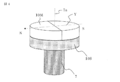
図4と図5はセンサ用永久磁石(被検出部)10の部分の斜視図である。
図4は円筒形状を有する構成例を示す。永久磁石10Mは図の矢印Yの方向に着磁されており、2極の永久磁石となっている。なお、この矢印Yは回転子の回転軸7aに垂直な平面上にある。永久磁石10Mは、ネオジのボンド磁石やネオジの焼結磁石、フェライト磁石などで構成され、永久磁石支持部10Sによって固定されている。
固定は接着剤でもよいし、ボンド磁石の場合は永久磁石支持部10Sと一体成形として互いを固定する構成にしてもよい。永久磁石10Mが発生する磁界への影響を小さくするため、永久磁石支持部10Sは、ステンレス系やアルミニウム系の非磁性金属や樹脂で構成するとよい。さらに永久磁石支持部10Sはシャフト7に圧入するなどして固定されている。
4 and 5 are perspective views of a portion of the sensor permanent magnet (detected portion) 10.
FIG. 4 shows a configuration example having a cylindrical shape. The
The fixing may be an adhesive, or in the case of a bonded magnet, the
図5は永久磁石が直方体形状を有する構成例を示す。永久磁石10Cは図の矢印Yの方向に着磁されており、2極の永久磁石となっている。なお、この矢印Yは回転子の回転軸7aに垂直な平面上にある。永久磁石10Cは、ネオジのボンド磁石やネオジの焼結磁石、フェライト磁石などで構成され、永久磁石支持部10Sによって固定されている。固定は接着剤でもよいし、ボンド磁石の場合は永久磁石支持部10Sと一体成形として互いを固定する構成にしてもよい。永久磁石10Cが発生する磁界への影響を小さくするため、永久磁石支持部10Sはステンレス系やアルミニウム系の非磁性金属や樹脂で構成するとよい。さらに永久磁石支持部10Sはシャフト7に圧入するなどして固定されている。
FIG. 5 shows a configuration example in which the permanent magnet has a rectangular parallelepiped shape. The
この永久磁石10M、10Cは、着磁方向が回転軸7aに垂直な平面上にあるため、磁気センサ付近に発生する磁束密度は回転軸7aに垂直な平面上のベクトル成分が主成分となり、回転軸方向の成分は非常に小さくなる。また、磁気センサ19は回転軸7aに垂直な平面上の磁束密度の向きを検出するため、偏心や振れがあっても磁束密度の向きはほとんど変化しないため、高精度に回転角度検出ができるという効果を有する。
Since the
図4のように円筒形状磁石を用いたので発生する磁束密度が均一となり、その結果、磁気センサ付近の磁束密度も均一となるため回転角度検出の精度を向上することができるという効果がある。
また、図5のように直方体形状磁石を用いた場合には、図4の円筒形状磁石と同様に、発生する磁束密度が均一となり、磁気センサ付近の磁束密度も均一となるため回転角度検出の精度を向上することができるという効果に加えて、直方体磁石は作成が容易で、焼結磁石の場合は複雑な形状と比べて材料歩留まりを向上できるという効果も得られる。
Since the cylindrical magnet is used as shown in FIG. 4, the generated magnetic flux density is uniform, and as a result, the magnetic flux density near the magnetic sensor is also uniform, so that the accuracy of rotation angle detection can be improved.
When a rectangular parallelepiped magnet is used as shown in FIG. 5, the generated magnetic flux density is uniform and the magnetic flux density near the magnetic sensor is uniform as in the cylindrical magnet of FIG. In addition to the effect that accuracy can be improved, a rectangular parallelepiped magnet can be easily produced, and in the case of a sintered magnet, the material yield can be improved as compared with a complicated shape.
以上のように、この発明の実施の形態1の電動駆動装置によれば、以下のような優れた効果が得られるものである。
(1)制御基板17と回転角度の検出部であるセンサ部300を別々の基板で構成することで制御基板17の実装面積を拡大できる。
(2)軸受け5Bとシャフト7端の回転角度センサの被検出部である永久磁石10との間の距離が小さくなるため振れ、偏心が小さくなる。その結果、回転角度検出の精度が向上し、モータの振動騒音を低減できるという効果が得られる。さらには、インバータ回路や制御基板17からの回転角度センサへのノイズ干渉を小さくすることができるという効果が得られる。
(3)センサ部300と制御基板17を電気的に接続する接続部材21がインバータ回路部分を貫通しているため、電動駆動装置を小型化できるという効果がある。
また、センサ部300と制御基板17は直接電気的に接続されているため、電動駆動装置を小型化できるという効果がある。
(4)センサ部300と制御基板17の電気的接続は、中間部材23によって位置決めされる構成となっているため、部品の精度の要求値を緩和することができるという効果がある。
(5)センサ部300と制御基板17の電気的接続はプレスフィットを用いることで、はんだを使わずに接続可能となる。接続部材21同士の間隔が小さくできるため、多くの接続部材21を並べて配置してもはんだによる接続の場合と比べて幅が小さくなるため電動駆動装置の小型化が可能となる。
(6)従来の特許文献1のものでは、回転センサが備えられた制御基板が回路部よりも後方に位置しているので軸受けから回転センサまでの距離が長いのに対し、本実施の形態1の構成では磁気センサ19が軸受け5Bに近い配置となっているため、軸受け5Bとセンサ用永久磁石10の距離が近い。このため、シャフトの端部での振れ、偏心が小さくなるため、結果としてセンサ用永久磁石の振れ、偏心が小さくなり、回転角度検出の精度が向上し、モータの振動・騒音が小さくなるという効果が得られる。
(7)更に、図1の実施の形態1においては、ヒートシンク16に凹部24を設けておりセンサ部300の基板20に実装された磁気センサ19とヒートシンク16の表面との間の距離を大きくしている。モータ駆動時にはヒートシンク16はスイッチング素子SWの発熱により温度が上昇する。もし、凹部24が設けられておらずヒートシンク16と磁気センサ19の距離が非常に近いと、ヒートシンク16の熱が磁気センサ19に伝わり、磁気センサ19の温度が非常に高くなってしまい、回転角度検出の精度が低下する場合や、過度の温度上昇により磁気センサ19が動作しなくなる場合も考えられる。
しかしながら、ヒートシンクに凹部24を設けることで、ヒートシンク16と磁気センサ19の距離を大きくすることができるので熱が伝わりにくくなり、磁気センサ19の温度上昇を低減し、回転角度の精度を向上できるという効果がある。
As described above, according to the electric drive device of
(1) The mounting area of the
(2) Since the distance between the bearing 5B and the
(3) Since the
Moreover, since the
(4) Since the electrical connection between the
(5) The electrical connection between the
(6) In the
(7) Furthermore, in the first embodiment of FIG. 1, the
However, by providing the
図6はこの発明の電動駆動装置を適用した自動車の電動パワーステアリング装置の説明図である。図6において、運転者はステアリングホイール(図示しない)を操舵し、そのトルクがステアリングシャフト(図示しない)を介してシャフト401に伝達される。このときトルクセンサ402が検出したトルクは電気信号に変換されケーブル(図示しない)を通じて第1のコネクタ13を介して制御部であるECU(Electronic Control Unit)200に伝達される。ECU200は、前述したように制御基板とモータを駆動するためのインバータ回路を備えている。一方、車速などの自動車の情報が電気信号に変換され、第2のコネクタ14を介してECU200に伝達される。ECU200はこのトルクと車速などの自動車の情報から、必要なアシストトルクを演算し、インバータを通じて永久磁石型モータ100に電流を供給する。モータ100はラック軸の移動方向(矢印Xで示す)に平行な向きに配置されている。また、ECU200への電源供給はバッテリやオルタネータから電源コネクタ15を介して送られる。永久磁石型モータ100が発生したトルクはベルト(図示せず)とボールネジ(図示せず)が内蔵されたギヤボックス403によって減速されハウジング404の内部にあるラック軸(図示せず)を矢印Xの方向に動かす推力を発生させ、運転者の操舵力をアシストする。これにより、タイロッド405が動き、タイヤが転舵して車両を旋回させることができる。永久磁石型モータ100のトルクによってアシストされ運転者は少ない操舵力で車両を旋回させることができる。なお、ラックブーツ406は異物が装置内に侵入しないように設けられている。また、モータ100とECU200は一体となっており、電動駆動装置を構成している。
FIG. 6 is an explanatory view of an electric power steering device for an automobile to which the electric drive device of the present invention is applied. In FIG. 6, the driver steers a steering wheel (not shown), and the torque is transmitted to the
このような電動パワーステアリング装置においては、モータが発生する振動・騒音が運転者に伝わるため、振動騒音は小さい方が望ましい。
本実施の形態1の電動駆動装置を自動車の電動パワーステアリング装置に用いると装置を小型化できるという効果が得られる。また、モータの回転角度検出の精度が向上するため、振動・騒音が小さくなるという効果も得られる。
なお、本実施の形態1ではモータは永久磁石型モータとしているが、モータは誘導電動機でも、シンクロナスリラクタンスモータでも、スイッチドリラクタンスモータでも良いことは言うまでもない。
In such an electric power steering apparatus, since vibration and noise generated by the motor are transmitted to the driver, it is desirable that the vibration noise is small.
When the electric drive device according to the first embodiment is used in an electric power steering device for an automobile, an effect that the device can be reduced in size can be obtained. In addition, since the accuracy of detecting the rotation angle of the motor is improved, the effect of reducing vibration and noise can be obtained.
In the first embodiment, the motor is a permanent magnet type motor, but it goes without saying that the motor may be an induction motor, a synchronous reluctance motor, or a switched reluctance motor.
なお、本実施の形態1で述べた回転角度センサの構成以外に、モータの極数に応じて多極に着磁されたリング形状の磁石の外周側に磁気検出素子を配置した構成も考えられる。
しかしながら、このような構成では、磁気検出素子の位置精度や多極に着磁されたリング形状永久磁石の着磁波形歪みや偏心などが角度誤差に与える影響が非常に大きい。
従って、電動パワーステアリング装置用の回転センサとしては課題が大きい。一方、本実施の形態1の構成では、回転軸と同軸上の位置に回転角度センサの検出部である磁気センサを設けたため、位置ずれの角度誤差への影響が小さい。また、被検出部であるセンサ用永久磁石は2極に着磁されているため、着磁波形の歪みが発生しにくく角度誤差を小さくできるという効果が得られる。さらに、2極の着磁で1Xの回転センサとして機能することが可能となるため、任意の極数のモータの駆動に対応できる。したがって、異なる極数のモータでも回転センサの設計を共通化できるという効果が得られる。さらに2極であるため構成が単純であるという効果もある。
In addition to the configuration of the rotation angle sensor described in the first embodiment, a configuration in which a magnetic detection element is arranged on the outer peripheral side of a ring-shaped magnet magnetized in multiple poles according to the number of poles of the motor is also conceivable. .
However, in such a configuration, the positional error of the magnetic detection element and the magnetization waveform distortion or eccentricity of the ring-shaped permanent magnet magnetized in multiple poles have a great influence on the angle error.
Therefore, there is a great problem as a rotation sensor for an electric power steering apparatus. On the other hand, in the configuration of the first embodiment, since the magnetic sensor which is the detection unit of the rotation angle sensor is provided at a position coaxial with the rotation axis, the influence of the positional deviation on the angle error is small. In addition, since the sensor permanent magnet as the detected portion is magnetized in two poles, the distortion of the magnetized waveform hardly occurs, and an effect that the angle error can be reduced can be obtained. Furthermore, since it becomes possible to function as a 1X rotation sensor by magnetization of two poles, it is possible to support driving of a motor having any number of poles. Therefore, the effect that the design of the rotation sensor can be made common even with motors having different numbers of poles can be obtained. Furthermore, since it has two poles, there is an effect that the configuration is simple.
実施の形態2.
図7は、磁気センサを2個搭載したこの発明の実施の形態2におけるセンサ部の説明図であり、(a)は前側から見た図、(b)は横側から見た図である。
図7において、基板20に磁気センサ19A、19Bが実装されている。この実施の形態2において図3と異なるのは、磁気センサが基板20の表と裏に1つずつ計2個の磁気センサ19Aと磁気センサ19Bが実装されている点である。また、2個の磁気センサ19A、19Bの位置は、モータの回転軸上に並ぶような位置となっている。
このような配置とすることで、被検出部であるセンサ用永久磁石が発生する磁界を検出する際、2個の磁気センサ19A、19Bがほぼ同じ向きの磁束密度ベクトルを検出することができるため、2個の磁気センサとも角度検出の精度を向上することができる。
FIGS. 7A and 7B are explanatory diagrams of the sensor unit according to the second embodiment of the present invention in which two magnetic sensors are mounted. FIG. 7A is a view seen from the front side, and FIG. 7B is a view seen from the side.
In FIG. 7,
With this arrangement, the two
基板20には接続部材21a、21bと一体となった支持部材22が設けられ、接続部材21a、21bと基板20はプレスフィットやはんだで固定されている。支持部材22から見て基板20とは反対側の接続部材21a、21bは制御基板と電気的に接続されるが、これもプレスフィットやはんだによって固定される。プレスフィットで固定される場合には接続部材21a同士、および21b同士の間隔を狭くとることができるため、センサ部と制御基板の小型化が実現できる。さらに、はんだを使わないため製造工程が簡略化されるという効果もある。
The
特に図7の実施の形態2では、磁気センサを2個搭載しているため、接続部材21a、21bが図3より多く必要となる。即ち、図7では磁気センサ19A用の接続部材21aが8本、磁気センサB用の接続部材bが8本の計16本の接続部材が設けられている。それに伴い、磁気センサ19A用の接続部材固定用穴21ahが8個、磁気センサ19B用の接続部材固定用穴21bhも8個設けられている。プレスフィットで接続する構成としていれば、このように接続部材が多くなっても、接続部材同士の間隔を狭くでき、センサ部を小型化できるという効果がある。
なお、基板20にはネジ穴25が3つ設けられていて、この穴25を利用して、ヒートシンクとネジによって固定される。なお、ネジ穴25の数は3つに限らないし、ネジ穴の位置も図7の位置に限らない。
In particular, in
The
以上のように、この発明の実施の形態2によれば、基板に2個の磁気センサを搭載したので、二重系でセンサ素子の一方が検出不能となっても,他のセンサ素子でモータの回転角度が検出できるという冗長性の効果が得られる。さらに、同一の基板上の表裏に搭載しているため2個の磁気センサがほぼ同じ向きの磁束密度ベクトルを検出することができるため、2個の磁気センサとも角度検出の精度を向上することができる。さらに、2個の磁気センサの角度情報からモータの回転子の回転角度を推定できるため、より高精度に回転角度を検出できるという効果がある。 As described above, according to the second embodiment of the present invention, since two magnetic sensors are mounted on the substrate, even if one of the sensor elements is undetectable in the dual system, the motor is driven by another sensor element. The effect of redundancy is that the rotation angle can be detected. In addition, since the two magnetic sensors can detect the magnetic flux density vector in almost the same direction because they are mounted on the front and back of the same substrate, both the two magnetic sensors can improve the accuracy of angle detection. it can. Furthermore, since the rotation angle of the rotor of the motor can be estimated from the angle information of the two magnetic sensors, the rotation angle can be detected with higher accuracy.
図8はこの発明の実施の形態2における電動駆動装置の全体構成を示す概略構成図である。図1との相違点は、センサ部300に磁気センサ19Aと19Bの2つの磁気センサが搭載されている点である。なお、センサ部300の接続部材は図7のように2つの磁気センサ19Aと磁気センサ19Bに対応した接続部材21aと接続部材21bとに分けた構成となっているが、図8では簡単のため省略して示している。
ヒートシンク16には凹部24が設けられており、この凹部24があることによってヒートシンク表面と磁気センサ19Aとの距離、ヒートシンク表面と磁気センサ19Bとの距離が大きくできる。その結果、ヒートシンク16の熱が磁気センサ19Aと磁気センサ19Bに伝わりにくくなることで、磁気センサ19Aと磁気センサ19Bの温度上昇を抑制することができる。その結果、回転角度の精度を向上できるという効果が得られる。
FIG. 8 is a schematic configuration diagram showing the overall configuration of the electric drive apparatus according to
The
実施の形態3.
図9は、この発明の実施の形態3における電動駆動装置の全体構成を示す概略構成図であり、中間部材に接続部材が一体となって構成された例である。
図1との相違点としては、センサ部300と中間部材23間を電気的に接続する第1の接続部材である接続部材21Fと、中間部材23と制御基板17を電気的に接続する第2の接続部材である接続部材21Rが中間部材23と一体になるように構成されている点である。例えば、中間部材23はインバータ回路部のバスバーを樹脂でインサート成形した構成とし、接続部材21Fと接続部材21Rも一体に成形された構成とすればよい。
FIG. 9 is a schematic configuration diagram showing the overall configuration of the electric drive apparatus according to
The difference from FIG. 1 is that a connecting
図10は、図9の電動駆動装置の各構成部品を軸方向に分解して並べた図である。
接続部材21Fと接続部材21Rは中間部材23と一体となって構成されている。センサ部300は基板20と磁気センサ19を有し、接続部材がない。このように、センサ部300が組み立てられた状態では接続部材がないため、突出した部分がなく、センサ部300の構造が単純となり、ハンドリング上も有利であるという効果がある。
FIG. 10 is a diagram in which the components of the electric drive device of FIG. 9 are disassembled and arranged in the axial direction.
The connecting
実施の形態4.
図11は、この発明の実施の形態4における電動駆動装置の全体構成を示す概略構成図であり、ヒートシンク16から見てモータ100とは反対側にセンサ部300を設けた構成の説明図である。
アルミニウム等の非磁性の金属で構成されたヒートシンク16に凹部24を設け、この凹部24のヒートシンク16の肉厚は他の部位より薄肉となっている。このヒートシンク薄肉部16Tを介して、センサ用永久磁石10の発生する磁束がヒートシンク16のモータ100とは反対側に到達する。この磁束を磁気センサ300が検出することによりモータ100の回転子の回転角度を検出することができる。
FIG. 11 is a schematic configuration diagram showing the overall configuration of the electric drive apparatus according to
A
このような構成とすることで、センサ部300と中間部材23および制御基板17との距離が小さくなるため接続部材21F、21Rの長さを短くでき、センサ部300の軽量化、材料のコスト低減ができるという効果がある。また、接続部材を貫通する穴をヒートシンク16に設けなくてよいため、ヒートシンク16の加工コストを低減できるという効果がある。なお、凹部24はモータ100側としたが、モータ100とは反対側に凹部を設けた構造としてもよい。
With such a configuration, since the distance between the
図12はこの発明の実施の形態4の変形例で、磁気センサを2個搭載した電動駆動装置の全体構成を示す概略構成図である。
図11との相違点は、センサ部300に磁気センサ19Aと磁気センサ19Bの2つの磁気センサが搭載されている点である。なお、センサ部300の接続部材は図7のように、2つの磁気センサ19Aと磁気センサ19Bに対応した接続部材21aと接続部材21bとに分けた構成となっているが、図12では簡単のため省略して示している。
FIG. 12 is a schematic configuration diagram showing the overall configuration of an electric drive apparatus having two magnetic sensors, which is a modification of the fourth embodiment of the present invention.
The difference from FIG. 11 is that two
以上のようにこの実施の形態によれば、2個の磁気センサ19A、19Bを搭載したのでセンサの機能に冗長性を持たせることができるという効果がある。さらに、同一の基板上の表裏に搭載しているため2個の磁気センサ19A、19Bがほぼ同じ向きの磁束密度ベクトルを検出することができるため、2個の磁気センサとも角度検出の精度を向上することができる。さらに、2個の磁気センサ19A、19Bの角度情報からモータの回転子の回転角度を推定できるため、より高精度に回転角度を検出できるという効果がある。
As described above, according to this embodiment, since the two
実施の形態5.
図13はこの発明の実施の形態5における電動駆動装置の全体構成を示す概略構成図であり、センサ部300とヒートシンク16との間に磁気シールド26を設けた構造の説明図である。磁気シールド26は鉄などの磁性材料の板を板金加工などで加工し、ヒートシンク16にネジ止めされる。このようにセンサ部300とヒートシンク16との間に磁気シールド26を設けると、大電流が流れるスイッチング素子SWやインバータ回路のバスバーなどが発生する磁束が遮蔽され、磁気センサ19にほとんど影響が及ばないため、回転角度検出の精度が向上するという効果がある。
Embodiment 5. FIG.
FIG. 13 is a schematic configuration diagram showing the overall configuration of the electric drive apparatus according to Embodiment 5 of the present invention, and is an explanatory diagram of a structure in which a
実施の形態6.
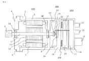
図14はこの発明の実施の形態6における電動駆動装置の全体構成を示す概略構成図であり、回転角度センサをレゾルバ500とした構成の説明図である。
図1との相違点はレゾルバ500をヒートシンク16に設けた点と、シャフト7の一方の端部に被検出部としてセンサ用永久磁石ではなく、レゾルバ回転子(図14では図示しない)を圧入して設けた点である。
FIG. 14 is a schematic configuration diagram showing the overall configuration of the electric drive apparatus according to
The difference from FIG. 1 is that a
この実施の形態6におけるレゾルバの構造を図15に示す。図15(a)は後側から見た図、図15(b)は横側から見た図を示す。図15において、電磁鋼板を積層して構成したレゾルバ回転子501はギャップパーミアンスが変化するように外形形状は凸部を有する形状としている。この凸部の数はモータの極数によって選定する。図15では5つの凸部を設けているので、1回転で5回のギャップパーミアンス変化が得られる。従って、極対数5のモータを駆動するのに適した軸倍角が5Xのレゾルバとして動作する。
なお、図15では5Xの例を示したが、1Xでもよいことは言うまでもない、また、モータの極対数に応じて設計すればよい。
The structure of the resolver in the sixth embodiment is shown in FIG. FIG. 15A is a view seen from the rear side, and FIG. 15B is a view seen from the side. In FIG. 15, the
Although FIG. 15 shows an example of 5X, it is needless to say that 1X may be used, and it may be designed according to the number of pole pairs of the motor.
レゾルバ回転子501の外側にレゾルバ固定子鉄心502が設けられている。このレゾルバ固定子鉄心502にはコイル503が巻き回されていて、コイル503は1相の励磁巻線と2相の出力巻線から構成されている。図15では省略しているが、樹脂製のカバー505などでコイル503は保護される。また、ヒートシンク16にレゾルバ固定子鉄心502を固定するためにネジ穴504を設けている。制御基板17との電気的接続は接続部材21によって行われ、プレスフィットやはんだによって固定される。接続部材21は樹脂製の支持部材22によって支えられている。レゾルバ固定子鉄心502、コイル503、カバー505、接続部材21、支持部材22とで検出部を構成している。
A
レゾルバ500は鉄心502とコイル503と接続部材21と支持部材22とカバー505で構成されており、半導体を用いた磁気センサと比べて構造が単純であり、耐振動性が向上するという効果がある。また磁気センサと比べて耐熱温度が高くなるため電動駆動装置の使用温度範囲を広げることができるという効果がある。また、ヒートシンク16に凹部を設けた構造とすることによって、レゾルバの一部をヒートシンク16に埋め込む配置とすることで、電動駆動装置の軸方向のサイズを短縮できるという効果がある。
さらに、レゾルバ500はコイル503がレゾルバ回転子501の周辺を全周囲うように配置されているため、レゾルバ回転子501が偏心してもその影響が小さくなる構成となっている。一方、モータの極数に応じて多極に着磁されたリング形状の磁石の外周側に磁気検出素子を配置する構成も考えられるが、このような構成で偏心の影響を小さくするにはリング形状の磁石の周辺に磁気検出素子を多数個配置する必要がありコストアップやセンサの大型化につながる。
The
Further, since the
この発明の電動駆動装置は、特に、車両用の電動パワーステアリング装置に用いて好適なものである。 The electric drive device of the present invention is particularly suitable for use in an electric power steering device for a vehicle.
1:固定子鉄心、2:電機子巻線、3:フレーム、5A、5B:軸受け、
7:シャフト、7a:回転軸、8:壁部、9:プーリー、10、10M、
10C:センサ用永久磁石、10S:永久磁石支持部、
13:第1のコネクタ、14:第2のコネクタ、15:電源コネクタ、
16:ヒートシンク、16T:ヒートシンク薄肉部、17:制御基板、
18:ケース、19、19A、19B:磁気センサ、20:基板、
21、21a、21b、21F、21R:接続部材、22:支持部材、
23:中間部材、24:凹部、25:ネジ穴、26:磁気シールド、
SW:スイッチング素子、100:永久磁石型モータ、
200:制御部(ECU)、300:センサ部、401:シャフト、
402:トルクセンサ、403:ギヤボックス、404:ハウジング、
405:タイロッド、406:ラックブーツ、500:レゾルバ、
501:レゾルバ回転子、502:レゾルバ固定子鉄心、
503:コイル、504:ネジ穴、505:カバー
1: stator core, 2: armature winding, 3: frame, 5A, 5B: bearing,
7: shaft, 7a: rotating shaft, 8: wall, 9: pulley, 10, 10M,
10C: permanent magnet for sensor, 10S: permanent magnet support,
13: first connector, 14: second connector, 15: power connector,
16: heat sink, 16T: heat sink thin part, 17: control board,
18: Case, 19, 19A, 19B: Magnetic sensor, 20: Substrate,
21, 21a, 21b, 21F, 21R: connection member, 22: support member,
23: Intermediate member, 24: Recess, 25: Screw hole, 26: Magnetic shield,
SW: switching element, 100: permanent magnet type motor,
200: control unit (ECU), 300: sensor unit, 401: shaft,
402: Torque sensor, 403: Gear box, 404: Housing,
405: Tie rod, 406: Rack boot, 500: Resolver,
501: resolver rotor, 502: resolver stator core,
503: Coil, 504: Screw hole, 505: Cover
Claims (5)
前記制御基板は前記ヒートシンクとは別体に構成されており、
前記回転角度センサの被検出部は、前記シャフトの端部先端に設けられた突部を有し磁性を有するレゾルバ回転子で構成され、
前記回転角度センサのセンサ部は、前記レゾルバ回転子の外周に設けられるレゾルバ固定子鉄心と、このレゾルバ固定子鉄心に巻回される励磁巻線と出力巻線で構成されるコイル、および前記コイルと前記制御基板とを電気的に接続する接続部材とで構成され、
前記コイルは前記レゾルバ回転子の周辺を全周囲うように配置され、
前記センサ部の前記レゾルバ固定子鉄心を前記ヒートシンクに設けられた凹部に配設すると共に、前記ヒートシンクおよび前記制御基板の配置は、前記モータのシャフトの回転軸に垂直な面に沿った配置としたことを特徴とする電動駆動装置。 An electric drive device comprising a motor and a control portion which is a drive device portion disposed on the opposite side to the output shaft side of the motor, wherein the end of the shaft on the opposite side to the output shaft side of the motor A rotation angle sensor to be detected, a sensor unit that is a detection unit of the rotation angle sensor is provided at a position coaxial with the rotation axis of the shaft, and the control unit includes a heat sink and the heat sink attached to the heat sink. In an electric drive device provided with an inverter circuit unit having a drive element for driving a motor, and a control board for controlling the output of the inverter circuit unit,
The control board is configured separately from the heat sink,
The detected part of the rotation angle sensor is composed of a resolver rotor having a magnet having a protrusion provided at the tip end of the shaft ,
The sensor unit of the rotation angle sensor includes a resolver stator core provided on an outer periphery of the resolver rotor, a coil composed of an excitation winding and an output winding wound around the resolver stator core, and the coil And a connecting member for electrically connecting the control board,
The coil is arranged to surround the entire periphery of the resolver rotor,
The resolver stator core of the sensor unit is arranged in a recess provided in the heat sink, and the arrangement of the heat sink and the control board is arranged along a plane perpendicular to the rotation axis of the motor shaft. The electric drive device characterized by the above-mentioned.
Priority Applications (1)
| Application Number | Priority Date | Filing Date | Title |
|---|---|---|---|
| JP2015130642A JP6198775B2 (en) | 2015-06-30 | 2015-06-30 | Electric drive |
Applications Claiming Priority (1)
| Application Number | Priority Date | Filing Date | Title |
|---|---|---|---|
| JP2015130642A JP6198775B2 (en) | 2015-06-30 | 2015-06-30 | Electric drive |
Related Parent Applications (1)
| Application Number | Title | Priority Date | Filing Date |
|---|---|---|---|
| JP2014539495A Division JP5936700B2 (en) | 2012-10-01 | 2012-10-01 | Electric drive |
Publications (2)
| Publication Number | Publication Date |
|---|---|
| JP2015202049A JP2015202049A (en) | 2015-11-12 |
| JP6198775B2 true JP6198775B2 (en) | 2017-09-20 |
Family
ID=54552850
Family Applications (1)
| Application Number | Title | Priority Date | Filing Date |
|---|---|---|---|
| JP2015130642A Active JP6198775B2 (en) | 2015-06-30 | 2015-06-30 | Electric drive |
Country Status (1)
| Country | Link |
|---|---|
| JP (1) | JP6198775B2 (en) |
Families Citing this family (11)
| Publication number | Priority date | Publication date | Assignee | Title |
|---|---|---|---|---|
| EP3379702B1 (en) * | 2015-11-20 | 2020-07-22 | Kabushiki Kaisha Yaskawa Denki | Motor and method for manufacturing motor |
| JP2017128283A (en) * | 2016-01-22 | 2017-07-27 | 株式会社アドヴィックス | Electric braking device for vehicle |
| US20170346429A1 (en) | 2016-05-31 | 2017-11-30 | Denso Corporation | Controller-integrated rotating electrical machine |
| JP6601328B2 (en) * | 2016-07-01 | 2019-11-06 | 株式会社デンソー | Motor equipment |
| DE102016212862A1 (en) * | 2016-07-14 | 2018-01-18 | Robert Bosch Gmbh | Power unit for an electric steering system |
| CN109792192B (en) * | 2016-09-30 | 2021-05-11 | 日本电产株式会社 | Motor and electric power steering apparatus |
| DE102016226293A1 (en) * | 2016-12-29 | 2018-07-05 | Robert Bosch Gmbh | Brushless electric machine |
| KR102032463B1 (en) * | 2017-11-16 | 2019-11-27 | 한양대학교 산학협력단 | Apparatus for measuring steering angle of vehicle |
| JP7157584B2 (en) * | 2018-08-01 | 2022-10-20 | 日立Astemo株式会社 | brake controller |
| KR20210144936A (en) | 2019-04-25 | 2021-11-30 | 아메리칸 액슬 앤드 매뉴팩쳐링, 인코포레이티드 | electric drive module |
| JP6977803B2 (en) * | 2020-03-18 | 2021-12-08 | 株式会社明電舎 | Motor assembly |
Family Cites Families (7)
| Publication number | Priority date | Publication date | Assignee | Title |
|---|---|---|---|---|
| JPH01171563U (en) * | 1988-05-18 | 1989-12-05 | ||
| JP3614380B2 (en) * | 2001-05-17 | 2005-01-26 | 三菱電機株式会社 | Electric power steering device |
| KR100927690B1 (en) * | 2005-01-31 | 2009-11-18 | 도요타 지도샤(주) | Resolver fixing structure |
| JP2007060734A (en) * | 2005-08-22 | 2007-03-08 | Mitsubishi Electric Corp | Rotary electric machine |
| JP2007318972A (en) * | 2006-05-29 | 2007-12-06 | Jtekt Corp | Electric motor and electrically powered steering system |
| JP2010028925A (en) * | 2008-07-16 | 2010-02-04 | Asmo Co Ltd | Electric motor and motor for electric power steering device |
| JP5363136B2 (en) * | 2009-02-13 | 2013-12-11 | 株式会社ミツバ | Brushless motor |
-
2015
- 2015-06-30 JP JP2015130642A patent/JP6198775B2/en active Active
Also Published As
| Publication number | Publication date |
|---|---|
| JP2015202049A (en) | 2015-11-12 |
Similar Documents
| Publication | Publication Date | Title |
|---|---|---|
| JP5936700B2 (en) | Electric drive | |
| JP6198775B2 (en) | Electric drive | |
| JP6246325B2 (en) | Electric motor and electric power steering apparatus using the same | |
| US8471418B2 (en) | Motorized equipment | |
| JP6124999B2 (en) | Permanent magnet type motor for electric power steering | |
| JP5642262B2 (en) | Motor drive device | |
| JP6485824B2 (en) | Electric drive | |
| JP6157652B2 (en) | Permanent magnet type motor | |
| JP7424344B2 (en) | Electric drive device and electric power steering device | |
| EP3139478B1 (en) | Permanent magnet motor | |
| JPWO2015011747A1 (en) | Permanent magnet type motor and electric power steering device | |
| JP6771848B2 (en) | Electric drive | |
| JP2018207639A (en) | Electric drive device, and electric power steering device | |
| JP6261776B2 (en) | Electric drive |
Legal Events
| Date | Code | Title | Description |
|---|---|---|---|
| A131 | Notification of reasons for refusal |
Free format text: JAPANESE INTERMEDIATE CODE: A131 Effective date: 20160705 |
|
| A521 | Written amendment |
Free format text: JAPANESE INTERMEDIATE CODE: A523 Effective date: 20160825 |
|
| A131 | Notification of reasons for refusal |
Free format text: JAPANESE INTERMEDIATE CODE: A131 Effective date: 20170131 |
|
| A521 | Written amendment |
Free format text: JAPANESE INTERMEDIATE CODE: A523 Effective date: 20170224 |
|
| TRDD | Decision of grant or rejection written | ||
| A01 | Written decision to grant a patent or to grant a registration (utility model) |
Free format text: JAPANESE INTERMEDIATE CODE: A01 Effective date: 20170725 |
|
| A61 | First payment of annual fees (during grant procedure) |
Free format text: JAPANESE INTERMEDIATE CODE: A61 Effective date: 20170822 |
|
| R151 | Written notification of patent or utility model registration |
Ref document number: 6198775 Country of ref document: JP Free format text: JAPANESE INTERMEDIATE CODE: R151 |
|
| R250 | Receipt of annual fees |
Free format text: JAPANESE INTERMEDIATE CODE: R250 |
|
| R250 | Receipt of annual fees |
Free format text: JAPANESE INTERMEDIATE CODE: R250 |
|
| R250 | Receipt of annual fees |
Free format text: JAPANESE INTERMEDIATE CODE: R250 |