JP6197702B2 - Input method, program, and input device - Google Patents
Input method, program, and input device Download PDFInfo
- Publication number
- JP6197702B2 JP6197702B2 JP2014046159A JP2014046159A JP6197702B2 JP 6197702 B2 JP6197702 B2 JP 6197702B2 JP 2014046159 A JP2014046159 A JP 2014046159A JP 2014046159 A JP2014046159 A JP 2014046159A JP 6197702 B2 JP6197702 B2 JP 6197702B2
- Authority
- JP
- Japan
- Prior art keywords
- head
- terminal
- input
- relative
- movement
- Prior art date
- Legal status (The legal status is an assumption and is not a legal conclusion. Google has not performed a legal analysis and makes no representation as to the accuracy of the status listed.)
- Active
Links
Images


Description
本件は、頭部の動作で端末に情報を入力する入力方法,プログラム及び入力装置に関する。 The present case relates to an input method, a program, and an input device for inputting information to a terminal by movement of the head.
近年、人体に装着した状態での利用が想定されたコンピューターやガジェットなどのデバイス(ウェアラブルデバイス)が開発されている。これらのデバイスでは、タッチ入力やペン入力,音声入力といった種々のUI(User Interface,ユーザーインタフェース)が採用されている。一方、これらのUIは、必ずしも日常的な業務に適した操作環境を提供するものとはいえない。例えば、工場,店舗,病院などに提供されるICT(Information and Communication Technology)サービスでは、業務に係る作業を中断することなく、自然な動作でデバイスを操作できるUIが望まれる。 In recent years, devices (wearable devices) such as computers and gadgets that are supposed to be used while worn on a human body have been developed. These devices employ various UIs (User Interfaces) such as touch input, pen input, and voice input. On the other hand, these UIs do not necessarily provide an operating environment suitable for daily work. For example, in an ICT (Information and Communication Technology) service provided to factories, stores, hospitals, etc., a UI that can operate a device with natural operation without interrupting work related to work is desired.
そこで、頭部の姿勢をコンピューターへの入力操作として認識させるUI技術が開発されている。例えば、頭部に加速度センサーを取り付けて頭の向きを検出し、その方向に対応する処理をコンピューターに実施させるものである。また、頭部の方向だけでなく視線の方向も併せて検出し、これらを入力操作として認識させるUI技術も提案されている(特許文献1,2参照)。
Therefore, UI technology that recognizes the posture of the head as an input operation to a computer has been developed. For example, an acceleration sensor is attached to the head to detect the direction of the head, and the computer performs processing corresponding to the direction. In addition, UI technology that detects not only the direction of the head but also the direction of the line of sight and recognizes them as input operations has also been proposed (see
頭部の動作を活用したUIは、自然な動作によるデバイスの操作環境を提供しうる。しかしながら、頭部の動作は、そのときの姿勢や視認対象との位置関係によって変化することがあるため、動作の認識精度を向上させることが困難である。また、頭部の運動状態を把握する上では、静的な状態(例えば、方向や傾きなど)だけでなく、動的な状態(例えば、回転量,移動速度,移動の激しさなど)を考慮することが望ましい。一方、既存の技術ではおもに前者が考慮されており、後者が十分に考慮されていないため、動作の認識精度を向上させにくい。 A UI that utilizes head movements can provide a device operating environment with natural movements. However, since the movement of the head may vary depending on the posture at that time and the positional relationship with the visual recognition target, it is difficult to improve the recognition accuracy of the movement. In addition, in understanding the movement state of the head, not only the static state (for example, direction and inclination) but also the dynamic state (for example, rotation amount, movement speed, intensity of movement, etc.) is considered. It is desirable to do. On the other hand, in the existing technology, the former is mainly considered, and the latter is not sufficiently considered, so that it is difficult to improve the recognition accuracy of the operation.
本件の目的の一つは、このような課題に鑑み創案されたもので、動作の認識精度を向上させることである。また、前記目的に限らず、後述する「発明を実施するための形態」に示す各構成により導かれる作用効果であって、従来の技術によっては得られない作用効果を奏することも本件の他の目的として位置付けることができる。 One of the purposes of the present case was created in view of such a problem, and is to improve the recognition accuracy of the motion. In addition, the present invention is not limited to the above-described purpose, and is an operational effect derived from each configuration shown in “Mode for Carrying Out the Invention” to be described later. Can be positioned as a purpose.
開示の入力方法は、頭部の動作を用いて端末に情報を入力する入力方法である。この入力方法では、前記端末及び前記頭部の相対的な傾きを取得し、前記傾きに基づき、前記情報の入力に係る動作を選別する。また、選別された前記動作における前記頭部の回転強度を算出し、前記回転強度に基づき、前記動作の入力区間を確定する。 The disclosed input method is an input method in which information is input to the terminal using the motion of the head. In this input method, the relative inclination of the terminal and the head is acquired, and the operation related to the input of the information is selected based on the inclination. Further, the rotational strength of the head in the selected motion is calculated, and the input section of the motion is determined based on the rotational strength.
開示の技術によれば、動作の認識精度を向上させることができる。 According to the disclosed technique, the recognition accuracy of the operation can be improved.
以下、図面を参照して、頭部の動作で端末に情報を入力する入力装置,入力方法及びプログラムに係る実施の形態を説明する。ただし、以下に示す実施形態はあくまでも例示に過ぎず、実施形態で明示しない種々の変形や技術の適用を排除する意図はない。すなわち、本実施形態をその趣旨を逸脱しない範囲で種々変形(実施形態及び各変形例を組み合わせる等)して実施することができる。 DESCRIPTION OF EMBODIMENTS Embodiments relating to an input device, an input method, and a program for inputting information to a terminal by head movement will be described below with reference to the drawings. However, the embodiment described below is merely an example, and there is no intention of excluding various modifications and technical applications that are not explicitly described in the embodiment. That is, the present embodiment can be implemented with various modifications (combining the embodiments and each modification) without departing from the spirit of the present embodiment.
[1.制御の概要]
本実施形態の入力装置,入力方法及びプログラムは、コンピューターにジェスチャーUIを提供するものである。このジェスチャーUIでは、頭部の動作がコンピューターへの入力操作として認識され、その入力操作の情報がコンピューターに入力される。ここでいうコンピューターには、電子計算機を内蔵し可搬性を有する装置が含まれる。例えば、携帯電話機,スマートフォン,インターネット端末といった携帯情報端末や、ノートパソコン,スレートパソコンといったパーソナルコンピューター、あるいは、音楽プレーヤー,カメラ,ビデオプレーヤー,携帯型ゲーム機,GPS(Global Positioning System)装置,リモコン装置などの電子機器類(ガジェット)がこれに含まれる。以下、入力操作の情報が入力されるこれらのコンピューター全般のことを単に「端末」と呼ぶ。
[1. Overview of control]
The input device, input method, and program of this embodiment provide a gesture UI to a computer. In this gesture UI, the movement of the head is recognized as an input operation to the computer, and information on the input operation is input to the computer. The computer referred to here includes a portable device with a built-in electronic computer. For example, portable information terminals such as mobile phones, smartphones, Internet terminals, personal computers such as notebook computers and slate computers, music players, cameras, video players, portable game machines, GPS (Global Positioning System) devices, remote control devices, etc. This includes electronic devices (gadgets). Hereinafter, these computers in which input operation information is input are simply referred to as “terminals”.
本実施形態では、端末に対する頭部の相対的な動作から入力操作の内容が解釈され、その情報が端末に入力される。端末及び頭部のそれぞれには、端末及び頭部のそれぞれの姿勢や運動状態を計測する計測装置が設けられ、それぞれの計測結果に基づいて端末及び頭部の相対的な動作が把握される。ここでいう動作には、頭部のねじれ角度や傾きといった静的な姿勢(ポーズ)だけでなく、時間経過とともに変化する動的な姿勢(モーションジェスチャー)が含まれる。また、ここでいう相対的な動作とは、端末に固定された座標系を基準とした頭部の動作(又は、頭部に固定された座標系を基準とした端末の動作)を意味する。すなわち、頭部の動作は、動作の主体となるユーザーの身体や地球に固定された地理座標系を基準とするのではなく、端末に対する動きとして把握される。 In this embodiment, the content of the input operation is interpreted from the relative movement of the head with respect to the terminal, and the information is input to the terminal. Each of the terminal and the head is provided with a measuring device that measures the posture and motion state of the terminal and the head, and the relative movement of the terminal and the head is grasped based on each measurement result. The motion here includes not only a static posture (pose) such as the twist angle and tilt of the head, but also a dynamic posture (motion gesture) that changes over time. In addition, the relative movement here means the movement of the head based on the coordinate system fixed to the terminal (or the movement of the terminal based on the coordinate system fixed to the head). In other words, the motion of the head is grasped as a motion with respect to the terminal, not based on a user's body that is the subject of the motion or a geographical coordinate system fixed to the earth.
端末及び頭部の動作を計測する計測装置としては、三軸加速度センサーや三軸ジャイロスコープ、あるいはこれらを内蔵する慣性計測装置(IMU,Inertial Measurement Unit)が用いられる。計測装置は、端末及び頭部のそれぞれに設けられる。端末側の計測装置は端末に固定,内蔵され、頭部側の計測装置は頭部に装着される頭部ガジェットに固定,内蔵される。頭部ガジェットは、頭部に対して着脱自在に設けられ、かつ、頭部の動作によって脱落しない程度に堅固に取り付け可能とされる。計測装置は、それぞれの動作に対応するパラメーターを検出,取得,算出し、時系列のデータとして出力する。 As a measurement device for measuring the movement of the terminal and the head, a triaxial acceleration sensor, a triaxial gyroscope, or an inertial measurement device (IMU, Inertial Measurement Unit) incorporating them is used. The measuring device is provided in each of the terminal and the head. The terminal-side measuring device is fixed and built in the terminal, and the head-side measuring device is fixed and built in the head gadget attached to the head. The head gadget is detachably attached to the head and can be firmly attached to the extent that the head gadget does not fall off due to the movement of the head. The measuring device detects, acquires and calculates parameters corresponding to each operation, and outputs them as time-series data.
本実施形態では、計測装置で計測された時系列のデータのうち、端末への入力操作に係る動作に対応するデータ区間が三段階に選別される。これらの選別は、計測装置で計測結果が取得される毎にリアルタイムに実施されるが、オフラインで(非リアルタイムで)実施することも可能である。この場合、計測装置で取得された計測結果を何らかのデータ記憶装置に記録しておけばよい。
第一の選別は、情報の入力に係る動作を選別するためのものであり、少なくとも端末及び頭部の相対的な傾きに基づいて行われる。第一の選別では、情報の入力に係る動作が実施された区間の候補が特定される。第一の選別条件が成立すると、頭部のジェスチャーによる端末への情報入力が有効な状態(Mode-In状態)とされる。一方、この第一の選別条件が不成立の場合には、ジェスチャーによる端末への情報入力が有効でない(無効化された)状態とされる(Mode-Out状態)。このように、第一の選別条件は、頭部のジェスチャーを参照するか否かを大まかに決定するON-OFFスイッチのように機能する。
In the present embodiment, among the time-series data measured by the measurement device, the data section corresponding to the operation related to the input operation to the terminal is selected in three stages. These selections are performed in real time each time a measurement result is acquired by the measurement device, but can also be performed off-line (non-real time). In this case, the measurement result acquired by the measurement device may be recorded in some data storage device.
The first selection is for selecting an operation related to input of information, and is performed based on at least the relative inclination of the terminal and the head. In the first selection, a candidate for a section in which an operation related to information input is performed is specified. When the first selection condition is satisfied, the information input to the terminal by the gesture of the head is valid (Mode-In state). On the other hand, when the first selection condition is not satisfied, the information input to the terminal by the gesture is not valid (invalidated) (Mode-Out state). In this way, the first selection condition functions like an ON-OFF switch that roughly determines whether or not to refer to the head gesture.
第二の選別は、第一の選別に続いて実施され、動作をさらに選別するためのものである。ここでは、第一の選別条件が成立したときの頭部の相対的な傾きを基準として、動作による視線の移動範囲が有効視野又は安定注視野内に収まっていることが確認される。第二の選別条件が成立した場合、その時点での動作を含むデータ区間は、正式なジェスチャー区間候補として特定される。第二の選別は、少なくとも頭部の動作による端末への情報入力が有効な状態(Mode-In状態)で実施される。また、端末への情報入力が有効でない状態(端末への情報入力が無効化されたMode-Out状態)になると、第二の選別は実施されない。少なくとも第一の選別条件が再び成立するまでは、第二の選別条件の判定が保留される。 The second sort is performed subsequent to the first sort and is intended to further sort operations. Here, based on the relative inclination of the head when the first selection condition is satisfied, it is confirmed that the movement range of the line of sight due to the operation is within the effective visual field or the stable focus field. When the second selection condition is satisfied, the data section including the operation at that time is specified as a formal gesture section candidate. The second selection is performed in a state (Mode-In state) in which information input to the terminal is effective by at least the operation of the head. In addition, when the information input to the terminal is not valid (Mode-Out state in which the information input to the terminal is invalidated), the second selection is not performed. The determination of the second selection condition is suspended until at least the first selection condition is satisfied again.
第三の選別は、動作の入力区間を確定するためのものであり、第一,第二の選別条件が成立した場合に、頭部の回転強度に基づいて行われる。ここでは、第一,第二の選別で特定されたジェスチャー区間候補内における頭部の回転強度が判定される。その結果、動作の主体(端末のユーザー)による意識的な動作(すなわち、情報の入力に係る動作)に対応するデータ区間が確定される。このように、無意識の動作(不随意運動)と意識的な動作(随意運動)とを区別して、意識的な動作を特定することをセグメンテーション(Segmentation)と呼ぶ。第三の選別条件は、セグメンテーションを通じて、頭部の動作がジェスチャー動作であるか否かを精度良く区別する機能を持つ。 The third sorting is for determining the input section of motion, and is performed based on the rotational strength of the head when the first and second sorting conditions are satisfied. Here, the rotational strength of the head in the gesture section candidate specified by the first and second selections is determined. As a result, a data section corresponding to a conscious operation (that is, an operation related to input of information) by an operation subject (terminal user) is determined. Thus, the distinction of unconscious movement (involuntary movement) and conscious movement (voluntary movement) to specify the conscious movement is called segmentation. The third sorting condition has a function of accurately discriminating whether or not the head motion is a gesture motion through segmentation.
「回転強度」とは、頭部の回転方向についての運動の激しさを表す指標値であり、頭部の回転運動に対応する変数の定積分値(積分区間を一定時間とした積分値)に対応するパラメーターである。この定積分値は、信号強度面積(SMA,Signal Magnitude Area)や一定時間内回転強度とも呼ばれる。
頭部が回転方向に激しく運動すれば、回転強度は増大する。回転強度の具体例には、頭部の角速度の定積分値,頭部の加速度の定積分値,端末に対する頭部の相対角速度の定積分値,端末に対する頭部の相対加速度の定積分値などが含まれ、あるいはこれらの定積分値に対応する値が含まれる。本実施形態では、計測装置で計測された角速度(AV,Angular Velocity)についての信号強度面積SMA(AV)に基づいて、回転強度の大きさが判断される。積分区間は、例えば0.1〜数秒の範囲内で適宜設定される。
“Rotational strength” is an index value that represents the intensity of motion in the direction of rotation of the head, and is a constant integral value of the variable corresponding to the rotational motion of the head. Corresponding parameter. This definite integral value is also called a signal intensity area (SMA, Signal Magnitude Area) or a rotation intensity within a certain time.
If the head moves violently in the direction of rotation, the rotational strength increases. Specific examples of rotational intensity include a definite integral value of the head angular velocity, a definite integral value of the head acceleration, a definite integral value of the relative angular velocity of the head relative to the terminal, and a definite integral value of the relative acceleration of the head relative to the terminal. Or a value corresponding to these definite integral values. In the present embodiment, the magnitude of the rotational intensity is determined based on the signal intensity area SMA (AV) for the angular velocity (AV, Angular Velocity) measured by the measuring device. The integration interval is appropriately set within a range of 0.1 to several seconds, for example.
ここで、頭部の回転運動を三軸(x軸,y軸,z軸)回りの回転運動に分解し、それぞれの角速度をωx(i),ωy(i),ωz(i)とおく。あるいは、端末に対する頭部の相対角速度を三軸回りの回転運動に分解し、それぞれの角速度をωx(i),ωy(i),ωz(i)とおく。三軸それぞれの角速度についての信号強度面積SMA(AV)は、それぞれの角速度ωx(i),ωy(i),ωz(i)の絶対値を定積分したものの合計に所定時間T(積分区間に相当)を乗じて求められる。式1中のiは、サンプリング順に付される序数である。角速度についての信号強度面積SMA(AV)は、序数iがjからj+Tまで変化する所定時間Tにおける、頭部ジェスチャーの回転運動の激しさを表す指標である。また、頭部の角速度をωx1(i),ωy1(i),ωz1(i)とおき、端末の角速度をωx2(i),ωy2(i),ωz2(i)とおけば、相対角速度についての信号強度面積SMA(AV)は、式2のように表現することができる。
Here, the rotational motion of the head is divided into rotational motions about three axes (x-axis, y-axis, z-axis), and the respective angular velocities are set as ωx (i), ωy (i), and ωz (i). Alternatively, the relative angular velocity of the head relative to the terminal is decomposed into rotational motions about three axes, and the respective angular velocities are set as ωx (i), ωy (i), and ωz (i). The signal intensity area SMA (AV) for each of the three axis angular velocities is the sum of the absolute values of the angular velocities ωx (i), ωy (i), and ωz (i) definitely integrated for a predetermined time T (in the integration interval). Equivalent). I in

角速度についての信号強度面積SMA(AV)を求めるための数式は、これに限定されない。例えば、それぞれの角速度ωx(i),ωy(i),ωz(i)が頭部の回転運動に与える影響を考慮して、それぞれの定積分値に所定の係数a,b,cを乗じたものを算出してもよい(式3参照)。あるいは、定積分値の合計に所定時間Tを乗じる代わりに、定積分値の合計を所定時間Tで除算して標準化し、単位時間あたりの回転運動の激しさを表す指標を算出してもよい(式4参照)。 The formula for obtaining the signal intensity area SMA (AV) for the angular velocity is not limited to this. For example, considering the effect of each angular velocity ωx (i), ωy (i), ωz (i) on the rotational motion of the head, each definite integral value was multiplied by a predetermined coefficient a, b, c. Things may be calculated (see Equation 3). Alternatively, instead of multiplying the sum of the definite integral values by the predetermined time T, the sum of the definite integral values may be standardized by dividing by the predetermined time T to calculate an index representing the intensity of the rotational motion per unit time. (See Equation 4).
回転運動の回転軸が既知であるとき、角速度の代わりに加速度の情報を用いて回転強度を求めることが可能である。例えば、頭部の回転運動はおもに頸部を中心とした回転運動となるため、頭部の角速度の代わりに、頭部の加速度を用いて回転強度を算出できる。ここで、頭部の加速度を三軸方向に分解し、それぞれの加速度をAx(i),Ay(i),Az(i)とおく。あるいは、端末に対する頭部の相対加速度を三軸方向に分解し、それぞれの加速度をAx(i),Ay(i),Az(i)とおく。三軸それぞれの加速度についての信号強度面積SMA(AC)は、式5に示すように、それぞれの加速度Ax(i),Ay(i),Az(i)の絶対値を定積分したものの合計に所定時間T(積分区間に相当)を乗じて求められる。なお、加速度についての信号強度面積SMA(AC)を求めるための数式はこれに限定されず、式2,式3,式4と同様に種々の変形を施した数式を用いることが可能である。
When the rotational axis of the rotational motion is known, it is possible to obtain the rotational intensity using the acceleration information instead of the angular velocity. For example, since the rotational motion of the head is mainly a rotational motion centered on the neck, the rotational intensity can be calculated using the acceleration of the head instead of the angular velocity of the head. Here, the acceleration of the head is decomposed in three axial directions, and the respective accelerations are set as Ax (i), Ay (i), and Az (i). Alternatively, the relative acceleration of the head with respect to the terminal is decomposed in three axial directions, and the respective accelerations are set as Ax (i), Ay (i), and Az (i). As shown in Equation 5, the signal intensity area SMA (AC) for each of the three axis accelerations is the sum of the absolute values of the respective accelerations Ax (i), Ay (i), and Az (i). It is obtained by multiplying by a predetermined time T (corresponding to the integration interval). It should be noted that the formula for obtaining the signal intensity area SMA (AC) for acceleration is not limited to this, and it is possible to use formulas with various modifications similar to
情報の入力に係る動作に対応するデータ区間が確定されると、そのデータ区間内に含まれる動作の特徴が抽出され、予め設定されたジェスチャーの特徴と照合されて、その動作に対応するジェスチャーが認識される。動作の特徴は、例えば動作の軌跡の形状や長さ,軌跡を構成する各軌跡点の速度ベクトル,各軌跡点の位置などに基づいて定義される。ジェスチャーが認識されると、そのジェスチャーに対応する入力操作の情報が端末に入力される。ジェスチャーの具体的な認識手法に関しては、公知の技術を適用可能である。 When the data section corresponding to the action related to the input of information is determined, the feature of the action included in the data section is extracted and compared with the preset feature of the gesture, and the gesture corresponding to the action is determined. Be recognized. The feature of the motion is defined based on, for example, the shape and length of the motion trajectory, the velocity vector of each trajectory point constituting the trajectory, the position of each trajectory point, and the like. When the gesture is recognized, input operation information corresponding to the gesture is input to the terminal. A known technique can be applied to a specific gesture recognition method.
[2.装置構成]
図1は、本実施形態に係る入力装置の全体構成を示す斜視図である。ここでは、頭部30のジェスチャーを用いて携帯型のタブレット端末10(端末)への入力操作の情報を制御するものを例示する。端末10を操作するユーザーの頭部30には、ヘッドセット型の頭部ガジェット20(ウェアラブルデバイス)が装着される。頭部ガジェット20は、頭部30の動作を検出し、その情報を端末10へと伝達する機能を持つ。頭部30のジェスチャーは、頭部ガジェット20から伝達された情報に基づいて端末10側で認識され、入力操作として解釈されるものとする。
[2. Device configuration]
FIG. 1 is a perspective view showing the overall configuration of the input device according to the present embodiment. Here, what controls the information of the input operation to the portable tablet terminal 10 (terminal) using the gesture of the
頭部ガジェット20の装置構成を図2に例示する。頭部ガジェット20の内部には、CPU21(Central Processing Unit),メモリ22,頭部IMU23,通信装置24が設けられる。これらの装置は、図示しない電力源(例えばボタン電池や電力供給ケーブル等)からの電力供給を受けて作動する。
CPU21は、制御ユニット(制御回路)や演算ユニット(演算回路),キャッシュメモリ(レジスタ群)等を内蔵するプロセッサである。また、メモリ22は、プログラムや作業中のデータが一時的に格納される短期記憶素子と、長期的に保持されるデータやプログラムが格納される長期記憶素子とを含む。前者は例えばROM(Read Only Memory),RAM(Random Access Memory)であり、後者は例えばフラッシュメモリやEEPROM(Electrically Erasable Programmable Read-Only Memory)等の不揮発性メモリである。
The device configuration of the
The
頭部IMU23は、頭部30の絶対的な傾きや姿勢,動作などを検出する慣性計測装置であり、頭部30の方向(向き),加速度,角速度を計測する。頭部IMU23には、ジャイロセンサー23A,加速度センサー23B,地磁気センサー23Cが内蔵される。ジャイロセンサー23Aは、頭部30に固定された座標軸である三軸(x軸,y軸,z軸)回りの角速度を検出する。加速度センサー23Bは、三軸(x軸,y軸,z軸)方向の加速度を検出する。地磁気センサー23Cは、地理座標系を基準とした頭部30の向き(姿勢,方位)を検出する。頭部IMU23から出力されるデータ形式は、例えば回転行列形式,四元数形式,オイラー角形式,ローデータ(生データ)形式などである。以下、頭部IMU23で得られたデータを「頭部データ」と呼ぶ。頭部データはCPU21や通信装置24に伝達され、必要に応じてメモリ22上に記録される。
通信装置24は、端末10との間で通信を行う装置である。頭部IMU23で得られた頭部データは、通信装置24を介してリアルタイムに端末10側へと伝達される。あるいは、メモリ22上に記録されたデータが通信装置24を介して端末10側へと伝達される。通信の種類は任意であり、有線通信であっても無線通信であってもよい。
The
The
端末10は、CPU11(プロセッサ),メモリ12,端末IMU13,通信装置14,RTC15,データベース16,ディスプレイ17を有し、好ましくは図示しないリムーバブルメディアの読み取り・書き出し装置も併設される。これらの装置は、任意の電力源(例えば内蔵バッテリーや電源ケーブル等)からの電力供給を受けて作動する。CPU11,メモリ12,端末IMU13,通信装置14は、頭部ガジェット20のCPU21,メモリ22,頭部IMU23,通信装置24と同様の装置である。
端末IMU13は、端末10の絶対的な傾きや姿勢,動作などを検出する慣性計測装置であり、端末10の方向(向き),加速度,角速度を計測する。端末IMU13には、ジャイロセンサー13A,加速度センサー13B,地磁気センサー13Cが内蔵され、端末10に固定された座標軸である三軸回りの角速度,三軸方向の加速度,地理座標系を基準とした端末10の向き(姿勢,方位)が検出される。以下、これらのデータを「端末データ」と呼ぶ。端末データは、リアルタイムにCPU11や通信装置14へと伝達される。また、頭部IMU23で得られた頭部データも、通信装置14を介してCPU11へと伝達される。これらの頭部データ及び端末データは、必要に応じてメモリ12上やリムーバブルメディア上に記録される。
The terminal 10 includes a CPU 11 (processor), a memory 12, a
The
RTC15(Real Time Clock)は、端末10の電源状態とは無関係に正確な時刻情報を保持,出力するための集積回路(チップ)である。全ての頭部データ及び端末データには、RTC15から出力される時刻情報が付加される。これにより、頭部データ及び端末データのそれぞれは、時系列のデータ群となる。
データベース16は、動作(ジェスチャー)の特徴とそのジェスチャーに対応する入力操作との対応関係を記憶する記憶装置である。ここには、動作の軌跡の形状や長さ,軌跡を構成する各軌跡点の速度ベクトル,各軌跡点の位置などの組み合わせに対する、コンピューターへの入力操作が予め定義される。ディスプレイ17は、CPU11での演算結果や端末データ,頭部データなどの情報を出力する表示装置である。本実施形態では、頭部30の動作認識に係るデータ区間の選別段階が表示される。例えば、第一の選別条件が成立すると、そのことを示す画像,記号などがディスプレイ17上に表示され、第二,第三の選別条件が判定されている最中であることがユーザーに報知される。なお、このようなユーザーへの報知は、省略してもよい。
The RTC 15 (Real Time Clock) is an integrated circuit (chip) for holding and outputting accurate time information regardless of the power state of the terminal 10. Time information output from the
The
[3.プログラム]
図3は、端末10のCPU11で実行される処理内容(プログラム1)を説明するためのブロック図である。これらの処理内容は、例えばアプリケーションプログラムとしてメモリ12の長期記憶素子に記録され、短期記憶素子のメモリ空間内に展開されて実行される。ここで実行される処理内容を機能的に分類すると、このプログラム1には、取得部2,選別部3,確定部4,軌跡・特徴抽出部5,リアルタイム照合・分類部6が設けられる。
[3. program]
FIG. 3 is a block diagram for explaining the processing content (program 1) executed by the
[3−1.取得部]
取得部2は、端末IMU13から伝達される端末データと頭部IMU23から伝達される頭部データとに基づき、端末10及び頭部30の動作に関する情報を取得するものである。取得部2には、頭部姿勢推定部2A,端末姿勢推定部2B,相対姿勢推定部2Cが設けられる。
頭部姿勢推定部2Aは、頭部データに基づいて地理座標系を基準とした頭部30の姿勢を推定する。頭部30の姿勢(向き)は、地磁気センサー23Cで検出される地磁気方向から推定でき、頭部30の停止時における加速度データからも推定できる。あるいは、ドリフトによるオフセットやノイズの影響が小さければ、角速度の積分値を用いて推定してもよい。頭部姿勢推定部2Aは、頭部30の姿勢を地理座標系に対するピッチ角,ヨー角,ロール角でリアルタイムに算出し、RTC15から出力される時刻情報を付加して相対姿勢推定部2Cに伝達する。なお、地理座標系に対するピッチ角,ヨー角,ロール角の定義は任意に設定可能である。本実施形態では、正面を北向きとした物体の回転運動を基準として東西方向をピッチ角の回転軸方向とし、鉛直上下方向をヨー角の回転軸方向とする。
[3-1. Acquisition Department]
The
The head
端末姿勢推定部2Bは、端末データに基づいて地理座標系を基準とした端末10の姿勢を推定する。端末姿勢推定部2Bは、端末10の姿勢を地理座標系に対するピッチ角,ヨー角,ロール角でリアルタイムに算出し、時刻情報を付加して相対姿勢推定部2Cに伝達する。
相対姿勢推定部2Cは、端末10及び頭部30の相対的な傾きを推定する。ここでは、ピッチ方向,ヨー方向,ロール方向の三軸についての相対的な傾き(すなわち、相対ピッチ角θ,相対ヨー角ψ,相対ロール角φ)が推定される。相対姿勢推定部2Cは、同一時刻に取得された端末10の傾きと頭部30の傾きとの差分をリアルタイムに算出する。ここで算出された相対的な傾きの情報には時刻情報が付加され、選別部3に伝達される。
The terminal
The relative
[3−2.選別部]
選別部3は、取得部で取得された相対的な傾きの情報に基づき、ジェスチャーによる操作入力に対応する動作を選別するものである。選別部3には、ピッチ角範囲判定部3A,有効視野判定部3B,区間候補特定部3Cが設けられる。
[3-2. Sorting unit]
The
ピッチ角範囲判定部3Aは、端末10及び頭部30のピッチ角が適切であることを確認する。ここでは、第一の選別条件に基づいて、ジェスチャー動作に対応するデータ区間の候補が特定される。第一の選別条件には、少なくとも以下の条件Aが含まれる。本実施形態では、以下の条件A〜Cの全てが成立した場合に、第一の選別条件が満たされたものとし、ディスプレイ上にそのことを示す画像,記号などを表示する。
=第一の選別条件=
A.相対ピッチ角θが所定値未満である
B.端末10のピッチ角が所定範囲内にある
C.頭部30のピッチ角が所定範囲内にある
The pitch angle range determination unit 3A confirms that the pitch angles of the terminal 10 and the
= First selection condition =
A. The relative pitch angle θ is less than a predetermined value B. B. The pitch angle of the terminal 10 is within a predetermined range. The pitch angle of the
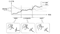
これらの条件と端末10及び頭部30のピッチ角との関係について、図4を用いて説明する。条件A中の相対ピッチ角θは、実線で示す頭部30のピッチ角と破線で示す端末10のピッチ角との差分に相当する。条件Aが成立するとき、頭部30のピッチ角と端末10のピッチ角とが同程度であり、頭部30の向きが端末10のディスプレイ17に対してほぼ垂直な姿勢となる。以下、ここで判定される所定値のことを所定値P0と表記する。
The relationship between these conditions and the pitch angles of the terminal 10 and the
条件B,条件Cは、端末10及び頭部30の各々のピッチ角が、所定の識別角度レンジP1〜P2内にあることを確認するためのものである。ディスプレイ17の向きが極端に下向きである場合や、頭部30の向きが極端に上向きである場合には、これらの条件が不成立となる。図4中で条件A〜Cの全てが成立するのは時刻t1〜t2の範囲(入力候補区間)となる。なお、ソファや布団に横になった姿勢でのジェスチャー操作を許容する場合には、条件B,条件Cで判定される所定範囲(識別角度レンジP1〜P2)を拡大するか、条件B,条件Cを省略してもよい。
Conditions B and C are for confirming that the pitch angles of the terminal 10 and the
有効視野判定部3Bは、ピッチ角範囲判定部3Aで第一の選別条件が成立した状態で、ジェスチャー動作に対応するデータ区間の候補をさらに絞り込むためのものである。ここでは、第二の選別条件に基づき、人の頭部運動による注視動作に関する特性を利用して、ジェスチャーによる操作入力に対応する動作が選別される。すなわち、相対ピッチ角θ及び相対ヨー角ψが有効視野に対応する範囲内で変動している間は、その動作をジェスチャーによる操作入力に対応する動作として選別する。一方、相対ピッチ角θ及び相対ヨー角ψの変動範囲が有効視野に対応する範囲外に飛び出した場合には、その時点でその動作がジェスチャーによる操作入力に対応する動作でなくなったものと判断する。
The effective visual
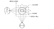
有効視野とは、視野内において眼球運動だけで瞬時に情報を受容できる領域である。有効視野の形状は、例えば図5に示すように注視点を中心に広がる楕円状であり、その長軸方向(水平方向)に約30°の幅を持ち、短軸方向(垂直方向)に約20°の幅を持つ。これに倣い、有効視野判定部3Bは、相対ピッチ角θが第一範囲P3〜P4内(例えば±10°以内)で変動し、かつ、相対ヨー角ψが第二範囲Y1〜Y2内(例えば±15°以内)で変動するような頭部30の動作を、ジェスチャー動作として有効な動作であるものとして選別する。なお、第一範囲P3〜P4,第二範囲Y1〜Y2は、図5に示すように、0を含む範囲として設定されることが好ましい。
The effective visual field is an area in which information can be received instantaneously only by eye movement within the visual field. The shape of the effective field of view is, for example, an ellipse that spreads around the gazing point as shown in FIG. 5, has a width of about 30 ° in the major axis direction (horizontal direction), and is about It has a width of 20 °. Following this, the effective visual
図5は、真正面を見ている状態での一般的な有効視野の範囲を示している。一方、端末10に対する頭部30の向きが必ずしもディスプレイ17の真正面であるとは限らない。そこで、有効視野判定部3Bは、ピッチ角範囲判定部3Aで第一の選別条件が成立した状態での相対姿勢を「参考姿勢」という基準として設定し、この参考姿勢からの相対姿勢の変化が有効視野に対応する範囲内にあるか否かを判定する。
FIG. 5 shows a general effective visual field range when looking directly in front. On the other hand, the orientation of the
第二の選別条件を以下に例示する。本実施形態では、以下の条件D,Eがともに成立した場合に、第二の選別条件が満たされたものとする。
=第二の選別条件=
D.参考姿勢を基準として、相対ピッチ角θの変動が第一範囲内
E.参考姿勢を基準として、相対ヨー角ψの変動が第二範囲内
(第一範囲,第二範囲はともに有効視野に対応する範囲)
The second selection conditions are exemplified below. In the present embodiment, it is assumed that the second selection condition is satisfied when the following conditions D and E are both satisfied.
= Second selection condition =
D. F. Relative pitch angle θ is within the first range with reference posture as a reference. Relative yaw angle ψ fluctuation within the second range with reference posture as the reference (both the first range and the second range correspond to the effective field of view)
第二の選別では、第一の選別条件の成立時にたとえ頭部30の向きが端末10のディスプレイ17に対して垂直でなかったとしても、その姿勢を基準として水平方向に±15°,垂直方向に±10°の範囲内で頭部30が動作している間は、その動作がジェスチャー動作として有効なものと判断される。このような判定手法は、より厳密なジェスチャー区間候補の識別と、自然な頭部30の動きによる操作入力との両立に資する。
In the second sorting, even if the orientation of the
なお、有効視野の周囲には、眼球及び頭部30の運動で無理なく注視できる領域である安定注視野が存在する。安定注視野の形状は、注視点を中心とした楕円が下方に押し伸ばされて、注視点よりも下方の領域がやや広くなった形状である。その短軸方向(垂直方向)は第三範囲P5〜P6(例えば約45〜70°)の幅を持ち、長軸方向(水平方向)は第四範囲Y3〜Y4(例えば約60〜90°)の幅を持つ。したがって、第一の選別条件が成立したときに、端末10に対する頭部30の向きがディスプレイ17の真正面でなかったとしても、相対ピッチ角θ,相対ヨー角ψが安定注視野の外に出ることはない。
In addition, there exists a stable gaze field that is an area that can be glanced by the movement of the eyeball and the
区間候補特定部3Cは、第一,第二の選別条件がともに成立する動作が実施された期間を「ジェスチャー区間候補(動作区間候補)」として特定し、この区間内で取得された角速度の情報を確定部4に伝達する。ジェスチャー区間候補は、第一,第二の選別条件がともに成立した時刻から、第一,第二の選別条件の何れかが不成立となった時刻までの期間である。第一,第二の選別では、ピッチ角やヨー角の情報が用いられているのに対し、これに続く第三の選別では、ジャイロセンサー13A,23Aで検出された角速度の情報が用いられる。
The section
[3−3.確定部]
確定部4は、ジェスチャー区間候補の中から、ジェスチャー動作として認識される動作区間を確定するものである。確定部4には、差分算出部4A,回転強度算出部4B,区間確定部4Cが設けられる。
差分算出部4Aは、「ジェスチャー区間候補」として特定された区間内に取得された角速度の情報に基づき、端末10及び頭部30の角速度の差分(相対角速度)を算出する。ここでは、ピッチ方向,ヨー方向,ロール方向のそれぞれの角速度について、端末IMU13で得られた角速度と頭部IMU23で得られた値との差が算出される。このような差分の算出により、ジャイロセンサー13A,13Bのオフセット(初期姿勢差)が除去される。
[3-3. Final part]
The
The
ここで、端末10及び頭部30のヨー方向の角速度(ヨー角速度)の変動を図6(A)に例示する。図中の破線は端末IMU13で得られたピッチ角速度に対応し、実線は頭部IMU23で得られたピッチ角速度に対応する。差分算出部4Aは、破線と実線との差(一方から他方を減じた値、あるいはその絶対値)を相対ピッチ角速度ωx〔図6(B)参照〕として算出する。同様に、差分算出部4Aは、ロール角速度,ヨー角速度についての差分である相対ロール角速度ωy,相対ヨー角速度ωzを算出する。ここでの算出結果は回転強度算出部4Bに伝達される。
Here, the fluctuation of the angular velocity (yaw angular velocity) in the yaw direction of the terminal 10 and the
回転強度算出部4Bは、「ジェスチャー区間候補」として特定された区間内における頭部30の回転強度を算出する。ここでは、「角速度についての信号強度面積SMA(AV)」が回転強度として算出される。信号強度面積SMA(AV)の算出に係る所定時間Tは、例えば0.1〜1.0秒の範囲内で設定される。角速度の種類としては、頭部IMU23で得られた角速度(すなわち、生のヨー角速度,ロール角速度,ピッチ角速度)を用いてもよいが、好ましくは差分算出部4Aで算出された相対角速度を用いる。本実施形態の回転強度算出部4Bは、前述の式1,式2に従って、相対ピッチ角速度ωx,相対ロール角速度ωy,相対ヨー角速度ωzの三種を用いた信号強度面積SMA(AV)を算出し、その情報を区間確定部4Cに伝達する。なお、頭部30のジェスチャー動作においてはロール方向の回転運動が弱い場合が多いことから、相対ロール角速度ωyを省略して(ωy=0とみなして)信号強度面積SMA(AV)を算出してもよい。
The rotation
区間確定部4Cは、回転強度算出部4Bで算出された回転強度に基づき、ジェスチャー動作の入力区間を確定する。ここでは、信号強度面積SMA(AV)の値が所定の閾値A0以上となる期間がジェスチャー動作の入力区間(すなわち、情報の入力に係る動作に対応するデータ区間)として確定される。つまり、区間確定部4Cは、回転強度が所定強度以上となる期間を入力区間とする機能を持つ。
ここで、角速度の信号強度面積SMA(AV)の変化を図7に例示する。ジェスチャー動作の入力区間は、信号強度面積SMA(AV)が閾値A0以上となる時刻t3〜t4,時刻t5〜t6,時刻t7〜t8の区間である。これ以外の区間は、仮に何らかの動作がなされているとしても、ジェスチャー動作の入力区間ではないものと判断される。このような判断により、ジェスチャー以外の動作による小さなノイズがフィルタリングされる。その後、入力区間内に含まれる相対ピッチ角θ及び相対ヨー角ψの情報が抽出され、軌跡・特徴抽出部5に伝達される。
The
Here, a change in the signal intensity area SMA (AV) of the angular velocity is illustrated in FIG. The input period of the gesture motion is a period from time t 3 to t 4 , time t 5 to t 6 , and time t 7 to t 8 when the signal intensity area SMA (AV) is equal to or greater than the threshold A 0 . It is determined that the other section is not an input section for the gesture operation even if some operation is performed. By such determination, small noises caused by operations other than gestures are filtered. Thereafter, information on the relative pitch angle θ and the relative yaw angle ψ included in the input section is extracted and transmitted to the trajectory / feature extraction unit 5.
[3−4.その他]
軌跡・特徴抽出部5は、確定した入力区間内に含まれる相対ピッチ角θ,相対ヨー角ψに基づき、視線の移動軌跡を算出するものである。ここでは、頭部30の正面前方に仮想キャンバスがあるものと仮定して、仮想キャンバス上での視点(視線と仮想キャンバスとの交点)の移動軌跡が算出される。この算出に際し、入力区間内に含まれる相対ピッチ角θ,相対ヨー角ψの情報は、その入力区間のジェスチャーが認識されるまで、図示しないバッファに記録される。また、相対ピッチ角θの変化量は仮想キャンバス上での視点の垂直移動量に変換され、相対ヨー角ψの変化量は水平移動量に変換される。これらの変換により、図8(A)に示すように、入力区間内における視線の移動軌跡が描出される。また、軌跡・特徴抽出部5は、描出された移動軌跡の特徴を抽出する。ここで抽出される特徴の種類としては、軌跡の形状や長さ,軌跡を構成する各軌跡点の速度ベクトル,各軌跡点の位置などが挙げられる。これらの特徴の情報は、リアルタイム照合・分類部6に伝達される。
[3-4. Others]
The locus / feature extraction unit 5 calculates a movement locus of the line of sight based on the relative pitch angle θ and the relative yaw angle ψ included in the determined input section. Here, assuming that there is a virtual canvas in front of the
リアルタイム照合・分類部6は、軌跡・特徴抽出部5で抽出された視線の移動軌跡の特徴と、データベース16が記憶する動作(ジェスチャー)の特徴とを比較,照合することにより、頭部30のジェスチャーを認識する。具体的なジェスチャーの認識手法には公知のパターン認識手法を採用することができる。例えば、データベース16上に記録されている全ての動作の特徴に対して、視線の移動軌跡の特徴がどの程度類似しているのかを評価し、最も類似度の高い動作を選択する。
また、リアルタイム照合・分類部6は、認識されたジェスチャーに対応する入力操作の情報を出力する。例えば、図8(B)に示すジェスチャーが認識された場合、そのジェスチャーが「右方向への移動」の操作であると解釈される。あるいは、図8(C)に示す場合は、数字の「9」の入力操作であると解釈される。このように解釈された情報は、端末10に対する操作入力としてCPU11へと伝達される。
The real-time collation /
Further, the real-time collation /
[4.フローチャート]
図9,図10は、端末10におけるジェスチャーの入力方法の手順を説明するためのフローチャートである。これらのフローは、例えばメモリ12や図示しないリムーバブルメディアに記録されたアプリケーションプログラムによる制御手順に対応するものであり、CPU11に読み込まれて所定周期で繰り返し実行される。プログラムの実行周期は、例えば端末IMU13,頭部IMU23における端末データ,頭部データのサンプリングレートに応じた周期(例えば0.01秒以下)とされる。
[4. flowchart]
9 and 10 are flowcharts for explaining the procedure of the gesture input method in the terminal 10. These flows correspond to a control procedure by an application program recorded in the memory 12 or a removable medium (not shown), for example, and are read by the
[4−1.ジェスチャー区間候補の特定]
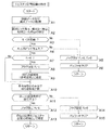
図9のフローは、ジェスチャー区間候補の特定に関するものであり、第一の選別条件と第二の選別条件とを判定する。このフローでは、相対姿勢フラグFCと回転範囲フラグFRとが用いられる。相対姿勢フラグFCは第一の選別条件が成立しているときにFC=1に設定されるフラグであり、回転範囲フラグFRは第二の選別条件が成立しているときにFR=1に設定されるフラグである。これらのフラグの初期値は0である。
[4-1. Identifying gesture segment candidates]
The flow in FIG. 9 relates to the identification of gesture section candidates, and the first selection condition and the second selection condition are determined. In this flow, a relative attitude flag F C and a rotation range flag F R are used. Relative orientation flag F C is a flag that is set to F C = 1 when the first selection condition is satisfied, the rotation range flag F R F R when the second selection condition is satisfied This flag is set to = 1. The initial value of these flags is 0.
ステップA1では、頭部データが頭部IMU23から頭部姿勢推定部2Aに入力されるとともに、端末データが端末IMU13から端末姿勢推定部2Bに入力される。また、頭部姿勢推定部2Aでは、頭部30のピッチ角,ヨー角,ロール角の推定演算がなされる。同様に、端末姿勢推定部2Bでは、端末10のピッチ角,ヨー角,ロール角の推定演算がなされる。
In step A1, head data is input from the
ステップA2では、相対姿勢推定部2Cにおいて、相対ピッチ角θ,相対ヨー角ψ,相対ロール角φの推定演算がなされ、端末10及び頭部30の相対的な傾きが取得される。また、ステップA3では、ピッチ角範囲判定部3Aにおいて、相対ピッチ角θが所定値未満であるか否かが判定される。この条件が不成立の場合には第一の選別条件も不成立となるため、ステップA5へ進んで相対姿勢フラグFC,回転範囲フラグFRがともに0に設定される。また、続くステップA6では、後述するジェスチャー認識のためにバッファリングされていたデータが消去(クリア)されてこのフローが終了する。
In step A2, the relative
ステップA3の条件が成立する場合にはステップA4に進み、端末10及び頭部30の各々のピッチ角が所定範囲内(所定の識別角度レンジP1〜P2内)にあるか否かが判定される。この条件が不成立の場合も、第一の選別条件が満たされないため、ステップA5に進む。反対に、この条件が成立した場合には、上記の条件A〜Cの全てが成立することとなり、第一の選別条件が成立するためステップA7に進む。
Proceeds to step A4 when the condition of step A3 is satisfied, determines whether the pitch angle of each of the
ステップA7では、相対姿勢フラグFCがFC=0である否かが判定される。このステップは、相対姿勢フラグFCの値が0から1に変化したタイミングを判断するためのステップである。ここですでにFC=1であるときには、ステップA8,A9をスキップしてステップA10に進む。一方、FC=0であるときはステップA8に進み、相対姿勢フラグFCがFC=1に設定される。その後のステップA9では、有効視野判定部3Bにおいて、その時点における姿勢が「参考姿勢」に設定される。例えば、その時点における相対ピッチ角θが所定値θ1であり、相対ヨー角ψが所定値ψ1であるとすれば、これらの所定値θ1,ψ1が記憶される。
In step A7, it is determined whether or not the relative posture flag F C is F C = 0. This step is a step for determining the timing when the value of the relative posture flag F C changes from 0 to 1. If F C = 1 already, steps A8 and A9 are skipped and the process proceeds to step A10. On the other hand, when F C = 0, the process proceeds to step A8, and the relative attitude flag F C is set to F C = 1. In subsequent step A9, the effective visual
ステップA10では、有効視野判定部3Bにおいて、参考姿勢との差分で相対姿勢が算出される。ここでは、相対ピッチ角θが所定値θ1からどの程度変動し、相対ヨー角ψが所定値ψ1からどの程度変動したのかが算出される。例えば、相対ピッチ角θから所定値θ1を減じた値が相対ピッチ角差分Δθとして算出され、相対ヨー角ψから所定値ψ1を減じた値が相対ヨー角差分Δψとして算出される。
In step A10, the effective visual
ステップA11では、参考姿勢を基準として、相対ピッチ角θ及び相対ヨー角ψが有効視野に対応する範囲内で変動しているか否かが判定される。ここでは、前ステップで算出された相対ピッチ角差分Δθが第一範囲内にあるか否か(例えば、P3≦Δθ≦P4であるか否か)が判定される。また、相対ヨー角差分Δψが第二範囲内にあるか否か(例えば、Y1≦Δψ≦Y2であるか否か)が判定される。これらの条件が成立すると、第二の選別条件も成立するため、ステップA12に進み、回転範囲フラグFRがFR=1に設定される。また、続くステップA13では、現在の動作が情報の入力動作に係る動作として選別される。つまり、現在の区間がジェスチャー区間候補として特定され、このフローが終了する。 In Step A11, it is determined whether or not the relative pitch angle θ and the relative yaw angle ψ are varied within a range corresponding to the effective visual field with reference to the reference posture. Here, it is determined whether or not the relative pitch angle difference Δθ calculated in the previous step is within the first range (for example, whether P 3 ≦ Δθ ≦ P 4 ). Further, it is determined whether or not the relative yaw angle difference Δψ is within the second range (for example, whether Y 1 ≦ Δψ ≦ Y 2 ). If these conditions are satisfied, since the second selection condition is also satisfied, the process proceeds to step A12, the rotation range flag F R is set to F R = 1. In the subsequent step A13, the current operation is selected as the operation related to the information input operation. That is, the current section is specified as a gesture section candidate, and this flow ends.
一方、ステップA11の条件が成立しない場合には、第二の選別条件が満たされないため、ステップA14に進んで回転範囲フラグFRがFR=0に設定される。また、続くステップA15では、後述するジェスチャー認識のためにバッファリングされていたデータが消去(クリア)されてこのフローが終了する。 On the other hand, if the condition of step A11 is not satisfied, the second selection condition is not satisfied, so the routine proceeds to step A14 where the rotation range flag F R is set to F R = 0. In the subsequent step A15, data buffered for gesture recognition described later is erased (cleared), and this flow ends.
[4−2.ジェスチャー区間の確定]
図10のフローは、ジェスチャー区間の確定に関するものであり、第三の選別条件を判定する。このフローは、図9に示すフローに並行して実行される。ステップB1では、相対姿勢フラグFC及び回転範囲フラグFRがともに1に設定されているか否かが判定される。ここでは、第一,第二の選別条件が成立した状態であることが確認される。この条件の不成立時にはステップB2に進み、後述するジェスチャー認識のためにバッファリングされていたデータが消去(クリア)されてこのフローが終了する。一方、この条件の成立時にはステップB3に進む。
[4-2. Confirm gesture section]
The flow of FIG. 10 relates to the determination of the gesture section, and the third selection condition is determined. This flow is executed in parallel with the flow shown in FIG. In step B1, whether relative orientation flag F C and the rotation range flag F R is set both to 1 is determined. Here, it is confirmed that the first and second selection conditions are satisfied. When this condition is not satisfied, the process proceeds to step B2, where data buffered for gesture recognition described later is erased (cleared), and this flow ends. On the other hand, when this condition is satisfied, the process proceeds to Step B3.
ステップB3では、差分算出部4Aにおいて、ジェスチャー区間候補として特定された区間内に取得された角速度の情報に基づき、端末10及び頭部30の角速度の差分が算出される。例えば、端末10のピッチ角速度から頭部30のピッチ角速度を減じた値が相対ピッチ角速度ωxとして算出される。同様に、相対ロール角速度ωy,相対ヨー角速度ωzも併せて算出される。続くステップB4では、回転強度算出部4Bにおいて、角速度についての回転強度SMA(VA)が算出される。ここでは、例えば式1,式2に従って角速度の信号強度面積SMA(AV)が回転強度として算出される。
In step B3, the
ステップB5では、角速度の信号強度面積SMA(AV)が閾値A0以上であるか否かが判定される。ここで、SMA(AV)≧A0であるときにはステップB6に進み、区間確定部4Cにおいて、その時点における頭部30の動作がジェスチャー区間に含まれる動作であると判断される。つまり、少なくともその時点の動作は、ジェスチャー動作の一部であると判断される。続くステップB7では、その時点における相対ピッチ角θ,相対ヨー角ψの情報が軌跡・特徴抽出部5に伝達され、バッファに記録される。また、ステップB8では、ジェスチャーに関するデータがバッファリングされていることを表すバッファフラグFBがFB=1に設定されて、このフローが終了する。第一,第二の選別条件が成立した状態で、角速度の信号強度面積SMA(AV)が閾値A0以上である限り、相対ピッチ角θ,相対ヨー角ψの情報が軌跡・特徴抽出部5に逐一バッファリングされることになる。
In step B5, whether the angular velocity signal intensity area SMA (AV) is the threshold value A 0 or not is determined. Here, when SMA (AV) ≧ A 0 , the process proceeds to step B6, and the
ステップB5でSMA(AV)<A0であるときにはステップB9に進み、バッファフラグFBがFB=1であるか否かが判定される。この条件が不成立の場合は、まだ相対ピッチ角θ,相対ヨー角ψの情報がバッファリングされていないため、そのままこのフローを終了する。これは例えば、第一,第二の選別条件が成立した直後であって、角速度の信号強度面積SMA(AV)が閾値A0未満である状態に相当する。 When SMA (AV) <A 0 in step B5, the process proceeds to step B9, and it is determined whether or not the buffer flag F B is F B = 1. If this condition is not satisfied, the information about the relative pitch angle θ and the relative yaw angle ψ has not been buffered yet, so this flow is terminated as it is. This corresponds to, for example, a state in which the angular velocity signal intensity area SMA (AV) is less than the threshold A 0 immediately after the first and second selection conditions are satisfied.
一方、ステップB9の条件の成立時にはステップB10に進む。ステップB10では、軌跡・特徴抽出部5において、バッファリングされた相対ピッチ角θ,相対ヨー角ψの情報に基づいて視線の移動軌跡が算出されるとともに、移動軌跡の特徴が抽出される。また、リアルタイム照合・分類部6では、移動軌跡の特徴とデータベース16上の動作(ジェスチャー)の特徴とが比較,照合され、頭部30のジェスチャーが認識されるとともに、そのジェスチャーに対応する入力操作の情報が出力される。
ジェスチャーの認識及び出力が完了したステップB11には、相対姿勢フラグFC,回転範囲フラグFR,バッファフラグFBが全て0にリセットされる。また、ステップB12では、その後の新たなジェスチャー入力に備えて、軌跡・特徴抽出部5のバッファが消去(クリア)される。
On the other hand, when the condition of step B9 is satisfied, the process proceeds to step B10. In step B10, the trajectory / feature extraction unit 5 calculates the movement trajectory of the line of sight based on the buffered information on the relative pitch angle θ and the relative yaw angle ψ, and extracts the trajectory features. In addition, the real-time collation /
In step B11 where the recognition and output of the gesture are completed, the relative posture flag F C , the rotation range flag F R , and the buffer flag F B are all reset to 0. In step B12, the buffer of the trajectory / feature extraction unit 5 is erased (cleared) in preparation for a new gesture input thereafter.
[5.作用,効果]
(1)上記の実施形態〔端末10(入力装置),端末10で実行されるジェスチャーの入力方法(図9,図10に示すフローチャート)及びジェスチャーの入力に係るプログラム1〕では、情報の入力に係る動作が実施された「データ区間(すなわちジェスチャー動作の入力区間)」を確定する際に、端末10及び頭部30の相対的な傾きに基づいて「ジェスチャー区間候補」が特定される。また、特定された「ジェスチャー区間候補」内における頭部30の回転強度に基づいて、最終的な「データ区間」が確定される。
つまり、「ジェスチャー区間候補」の特定には、相対的な傾きの情報が用いられるのに対し、その候補をさらに絞り込んで確定する際には、頭部30の回転運動の激しさを表す回転強度の情報が用いられる。
[5. Action, effect]
(1) In the above embodiment [the terminal 10 (input device), the gesture input method executed in the terminal 10 (the flowchart shown in FIGS. 9 and 10) and the
In other words, the relative inclination information is used to identify the “gesture section candidate”, but when further narrowing down and confirming the candidate, the rotation intensity indicating the intensity of the rotational motion of the
このような手法を採用することで、随意的なジェスチャー動作が行われた区間を精度よく把握することができ、セグメンテーションの精度を高めることができる。これにより、軌跡・特徴抽出部5で抽出される移動軌跡の特徴が適正化され、リアルタイム照合・分類部6での照合精度が向上する。したがって、ジェスチャー動作の認識精度を向上させることができる。
例えば、ユーザーによる意識的な随意運動と、無意識のうちに生じる不随意動作とを高精度に区別することができ、誤入力の発生確率を大幅に低減させることができる。また、ユーザーに拘束感を与えない自然な小さい頭部30の動きであっても、その動きを入力操作に係るジェスチャーとして判別することができる。
By adopting such a method, it is possible to accurately grasp a section in which an arbitrary gesture operation has been performed, and to improve the segmentation accuracy. As a result, the features of the movement trajectory extracted by the trajectory / feature extraction unit 5 are optimized, and the collation accuracy in the real-time collation /
For example, conscious voluntary movement by the user and involuntary movement that occurs unconsciously can be distinguished with high accuracy, and the probability of erroneous input can be greatly reduced. Further, even a natural small movement of the
(2)上記の実施形態では、条件Aに示すように、端末10及び頭部30の相対ピッチ角θが所定値未満の動作を選別している。相対ピッチ角θを用いてデータ区間の候補を特定することで、端末10に対する頭部30の動作を精度よく把握することができる。例えば、ソファや布団に横になった姿勢でのジェスチャー操作を許容することができ、動作の識別精度を向上させることができる。
(2) In the above-described embodiment, as shown in the condition A, an operation in which the relative pitch angle θ between the terminal 10 and the
(3)上記の実施形態では、条件B,条件Cに示すように、端末10及び頭部30の各々のピッチ角が所定範囲内にある動作を選別している。それぞれのピッチ角の角度範囲を制限することで、動作とは無関係な傾きを除外することができ、動作の識別精度を向上させることができる。例えば、図4中に示すように、ディスプレイ17の向きが極端に下向きである場合や、頭部30の向きが極端に上向きである場合の動作を認識対象から除外することができる。また、これらの状態では第一の選別条件が成立せず、ジェスチャーの認識に係るデータがバッファリングされないため、演算負荷を削減することができる。
(3) In the above embodiment, as shown in the condition B and the condition C, the operations in which the pitch angles of the terminal 10 and the
(4)上記の実施形態では、条件D,条件Eに示すように、相対ピッチ角θ,相対ヨー角ψの変動が有効視野に対応する範囲内であることを条件として動作が選別される。有効視野は、視野内において眼球運動だけで瞬時に情報を受容できる領域である。つまり、有効視野を超えるような頭部動作を伴うジェスチャーは、眼球運動だけで瞬時に情報を受容できない不自然な動作であるといえる。上記の実施形態では、このような不自然な動作が認識対象から除外されるため、ジェスチャー区間候補をより厳密に識別しつつ、頭部30の自然な動きによる操作入力を実現することができる。
(4) In the above embodiment, as shown in the conditions D and E, the operations are selected on the condition that the fluctuations in the relative pitch angle θ and the relative yaw angle ψ are within the range corresponding to the effective visual field. The effective visual field is an area in which information can be received instantaneously only by eye movement within the visual field. That is, it can be said that a gesture accompanied by a head movement exceeding the effective visual field is an unnatural movement that cannot receive information instantaneously only by eye movement. In the above embodiment, such an unnatural motion is excluded from the recognition target, so that it is possible to realize an operation input by natural movement of the
(5)上記の条件D,条件Eでは、参考姿勢を基準とした相対ピッチ角θ,相対ヨー角ψの変動が判定される。参考姿勢とは、第一の選別条件が成立した状態での相対姿勢である。つまり、条件D,条件Eの判定では、その判定がなされる直前における端末10と頭部30との相対的な位置関係に応じて、有効視野の中心位置が変更される。これにより、たとえ頭部30の向きが端末10のディスプレイ17に対して垂直でなかったとしても、その傾斜した視認姿勢を基準とした有効視野を設定することができる。したがって、ジェスチャー区間候補をより厳密に識別しつつ、頭部30の自然な動きによる操作入力を実現することができる。
(5) Under the above conditions D and E, changes in the relative pitch angle θ and the relative yaw angle ψ with respect to the reference posture are determined. The reference posture is a relative posture in a state where the first selection condition is satisfied. That is, in the determination of condition D and condition E, the center position of the effective visual field is changed according to the relative positional relationship between the terminal 10 and the
(6)上記の条件D,条件Eでは、相対ピッチ角θの変動が第一範囲P3〜P4内であり、かつ、相対ヨー角ψの変動が第二範囲Y1〜Y2内であるか否かが判定される。このように、相対ピッチ角θ及び相対ヨー角ψの変動が比較的小さいことを条件として第二の選別を実施することで、ジェスチャー区間候補をより厳密に識別することができ、動作の識別精度を向上させることができる。
(7)上記の実施形態では、区間確定部4Cにおいて、回転強度が所定強度以上となる期間がジェスチャー動作の入力区間として確定される。このように、回転方向についての運動の激しさを用いることで、頭部30の意識的な動作を精度よく把握することができ、動作の識別精度を向上させることができる。
(6) Under the above conditions D and E, the variation of the relative pitch angle θ is within the first range P 3 to P 4 and the variation of the relative yaw angle ψ is within the second range Y 1 to Y 2 . It is determined whether or not there is. As described above, by performing the second selection on the condition that the relative pitch angle θ and the relative yaw angle ψ are relatively small, it is possible to more precisely identify the gesture section candidate and to identify the motion identification accuracy. Can be improved.
(7) In the above-described embodiment, in the
(8)上記の実施形態では、式1,式2に示すように、頭部の回転強度に相当する角速度についての信号強度面積SMA(AV)が算出される。このような算出手法を採用することで、三軸全てについての頭部30の回転運動の激しさを定量的に評価することができ、動作の識別精度を向上させることができる。
(9)また、上記の実施形態では、差分算出部4Aで算出された相対角速度を用いて信号強度面積SMA(AV)を算出している。これにより、体動ノイズ(体動アーティファクト,歩行動作や乗り物の揺れなどに起因するノイズ)の影響を除去することができ、動作の識別精度を向上させることができる。
(8) In the above embodiment, as shown in
(9) In the above embodiment, the signal intensity area SMA (AV) is calculated using the relative angular velocity calculated by the
[6.変形例]
開示の実施形態の一例に関わらず、本実施形態の趣旨を逸脱しない範囲で種々変形して実施することができる。本実施形態の各構成及び各処理は、必要に応じて取捨選択することができ、あるいは適宜組み合わせてもよい。
[6. Modified example]
Regardless of an example of the disclosed embodiment, various modifications can be made without departing from the spirit of the present embodiment. Each structure and each process of this embodiment can be selected as needed, or may be combined suitably.
上述の実施形態では、図1に示すように、ヘッドセット型のウェアラブルデバイスを例示したが、頭部30の動きを取得するための手法はこれに限定されない。例えば、耳掛け型や眼鏡型のウェアラブルデバイスに頭部IMU23を内蔵させたものを用いてもよい。なお、端末10の内蔵カメラで撮影された画像を解析することで、端末10と頭部30との相対的な傾きや頭部30の回転強度を算出するような制御構成としてもよい。
In the above-described embodiment, as shown in FIG. 1, a headset-type wearable device is illustrated, but the method for acquiring the movement of the
また、上述の実施形態では、端末10の内部でジェスチャーを認識するものを例示したが、ジェスチャーの認識に係る制御を実施する主体は任意である。例えば、頭部ガジェット20の内部で上記のプログラム1を実行させてもよいし、端末10及び頭部ガジェット20以外のコンピューター上で実行させてもよい。この場合、制御を実施する主体は、有線又は無線通信により端末10及び頭部ガジェット20と通信可能とすることが好ましい。
Further, in the above-described embodiment, an example of recognizing a gesture inside the terminal 10 has been illustrated, but an entity that performs control related to gesture recognition is arbitrary. For example, the
また、上述の実施形態では、図3に示すプログラム1が端末10のメモリ12上に記録されたものを例示したが、プログラム1が記録される記録媒体はこれに限定されない。例えば、磁気記録媒体や光記録媒体などのコンピューターで読み取り可能な記録媒体に記録された形態で提供されてもよい。この場合、コンピューターはその記録媒体からプログラムを読み取り、内部記憶装置又は外部記憶装置に転送,格納して、プログラムを実行する。なお、上述の実施形態では、図3に示す機能がソフトウェア上で実施されるものを示したが、これらの機能の一部又は全部をハードウェア(論理回路)として設けてもよい。
In the above-described embodiment, the
[7.付記]
以上の変形例を含む実施形態に関し、さらに以下の付記を開示する。
[7−1.入力方法]
(付記1)
頭部の動作を用いて端末に情報を入力する入力方法において、
前記端末及び前記頭部の相対的な傾きを取得し、
前記傾きに基づき、前記情報の入力に係る動作を選別し、
選別された前記動作における前記頭部の回転強度を算出し、
前記回転強度に基づき、前記動作の入力区間を確定する
ことを特徴とする、入力方法。
(付記2)
前記端末に対する前記頭部の相対的な回転強度を算出する
ことを特徴とする、付記1記載の入力方法。
[7. Addendum]
The following additional remarks are disclosed with respect to the embodiment including the above modification.
[7-1. input method]
(Appendix 1)
In the input method to input information to the terminal using the movement of the head,
Obtaining a relative inclination of the terminal and the head;
Based on the inclination, the operation related to the input of the information is selected,
Calculate the rotational strength of the head in the selected movement,
An input method for determining an input section of the operation based on the rotation intensity.
(Appendix 2)
The input method according to
(付記3)
前記端末及び前記頭部の相対的なピッチ角が所定値未満の前記動作を選別する
ことを特徴とする、付記1又は2記載の入力方法。
(付記4)
前記端末及び前記頭部の各ピッチ角が所定範囲内にある前記動作を選別する
ことを特徴とする、付記1〜3の何れか1項に記載の入力方法。
(Appendix 3)
The input method according to
(Appendix 4)
The input method according to any one of
(付記5)
前記端末及び前記頭部の相対的なピッチ角及びヨー角の変動が有効視野に対応する範囲内である前記動作を選別する
ことを特徴とする、付記1〜4の何れか1項に記載の入力方法。
(付記6)
前記端末及び前記頭部の相対的なピッチ角及びヨー角に基づき、前記有効視野の基準位置を設定する
ことを特徴とする、付記5記載の入力方法。
(Appendix 5)
5. The operation according to any one of
(Appendix 6)
The input method according to claim 5, wherein a reference position of the effective visual field is set based on a relative pitch angle and yaw angle between the terminal and the head.
(付記7)
前記端末及び前記頭部の相対的なピッチ角の変動が第一範囲内であり、かつ、前記端末及び前記頭部の相対的なヨー角の変動が第二範囲内である前記動作を選別する
ことを特徴とする、付記5又は6記載の入力方法。
(付記8)
前記回転強度が所定強度以上となる期間を前記入力区間とする
ことを特徴とする、付記1〜7の何れか1項に記載の入力方法。
(Appendix 7)
The movement is selected in which the relative pitch angle variation between the terminal and the head is within a first range, and the relative yaw angle variation between the terminal and the head is within a second range. The input method according to
(Appendix 8)
The input method according to any one of
(付記9)
前記頭部の角速度についての信号強度面積(すなわち、前記頭部の角速度の定積分値に対応するパラメーター)を前記回転強度として算出する
ことを特徴とする、付記1〜8の何れか1項に記載の入力方法。
(付記10)
以下の式1を用いて前記信号強度面積を算出する
ことを特徴とする、付記9記載の入力方法。
The signal intensity area for the angular velocity of the head (that is, a parameter corresponding to a definite integral value of the angular velocity of the head) is calculated as the rotational intensity. The input method described.
(Appendix 10)
The input method according to appendix 9, wherein the signal intensity area is calculated using the following
[7−2.入力装置]
(付記11)
頭部の動作を用いて端末に情報を入力する入力装置であって、
プロセッサと、
メモリと、
前記端末及び前記頭部の相対的な傾きを取得する取得部と、
前記取得部で取得された前記傾きに基づき、前記情報の入力に係る動作を選別する選別部と、
前記選別部で選別された前記動作における前記頭部の回転強度を算出する算出部と、
前記算出部で算出された前記回転強度に基づき、前記動作の入力区間を確定する確定部と、
を備えたことを特徴とする、入力装置。
(付記12)
前記算出部が、前記端末に対する前記頭部の相対的な回転強度を算出する
ことを特徴とする、付記11記載の入力装置。
[7-2. Input device]
(Appendix 11)
An input device for inputting information to the terminal using the movement of the head,
A processor;
Memory,
An acquisition unit for acquiring a relative inclination of the terminal and the head;
Based on the inclination acquired by the acquisition unit, a selection unit that selects an operation related to the input of the information;
A calculation unit for calculating the rotational strength of the head in the movement selected by the selection unit;
A determination unit for determining an input section of the motion based on the rotation intensity calculated by the calculation unit;
An input device comprising:
(Appendix 12)
The input device according to
(付記13)
前記選別部は、前記端末及び前記頭部の相対的なピッチ角が所定値未満の前記動作を選別する
ことを特徴とする、付記11又は12記載の入力装置。
(付記14)
前記選別部は、前記端末及び前記頭部の各ピッチ角が所定範囲内にある前記動作を選別する
ことを特徴とする、付記11〜13の何れか1項に記載の入力装置。
(Appendix 13)
13. The input device according to
(Appendix 14)
The input device according to any one of
(付記15)
前記選別部は、前記端末及び前記頭部の相対的なピッチ角及びヨー角の変動が有効視野に対応する範囲内である前記動作を選別する
ことを特徴とする、付記11〜14の何れか1項に記載の入力装置。
(付記16)
前記選別部は、前記端末及び前記頭部の相対的なピッチ角及びヨー角に基づき、前記有効視野の基準位置を設定する
ことを特徴とする、付記15記載の入力装置。
(Appendix 15)
Any one of
(Appendix 16)
The input device according to
(付記17)
前記選別部は、前記端末及び前記頭部の相対的なピッチ角の変動が第一範囲内であり、かつ、前記端末及び前記頭部の相対的なヨー角の変動が第二範囲内である前記動作を選別する
ことを特徴とする、付記15又は16記載の入力装置。
(付記18)
前記確定部は、前記回転強度が所定強度以上となる期間を前記入力区間とする
ことを特徴とする、付記11〜17の何れか1項に記載の入力装置。
(Appendix 17)
The selection unit has a variation in relative pitch angle between the terminal and the head within a first range, and a variation in relative yaw angle between the terminal and the head within a second range. The input device according to
(Appendix 18)
The input device according to any one of
(付記19)
前記算出部が、前記頭部の角速度についての信号強度面積(すなわち、前記頭部の角速度の定積分値に対応するパラメーター)を前記回転強度として算出する
ことを特徴とする、付記11〜18の何れか1項に記載の入力装置。
(付記20)
前記算出部が、上記の式1を用いて前記信号強度面積を算出する
ことを特徴とする、付記19記載の入力装置。
(Appendix 19)
The calculation unit calculates a signal intensity area for the angular velocity of the head (that is, a parameter corresponding to a constant integral value of the angular velocity of the head) as the rotation intensity, The input device according to any one of the above.
(Appendix 20)
20. The input device according to appendix 19, wherein the calculation unit calculates the signal intensity
[7−3.プログラム(記録媒体)]
(付記21)
頭部の動作を用いて端末に情報を入力するプログラム〔又は、プログラムを記録したコンピューター読取可能な記録媒体〕において、
前記端末及び前記頭部の相対的な傾きを取得し、
前記傾きに基づき、前記情報の入力に係る動作を選別し、
選別された前記動作における前記頭部の回転強度を算出し、
前記回転強度に基づき、前記動作の入力区間を確定する
処理をコンピューターに実行させるプログラム〔又は、プログラムを記録したコンピューター読取可能な記録媒体〕。
(付記22)
前記端末に対する前記頭部の相対的な回転強度を算出する
処理をコンピューターに実行させる付記21記載のプログラム〔又は、プログラムを記録したコンピューター読取可能な記録媒体〕。
[7-3. Program (recording medium)]
(Appendix 21)
In a program (or a computer-readable recording medium in which the program is recorded) for inputting information to the terminal using the movement of the head,
Obtaining a relative inclination of the terminal and the head;
Based on the inclination, the operation related to the input of the information is selected,
Calculate the rotational strength of the head in the selected movement,
A program (or a computer-readable recording medium on which a program is recorded) that causes a computer to execute processing for determining an input interval of the operation based on the rotation intensity.
(Appendix 22)
The program according to
(付記23)
前記端末及び前記頭部の相対的なピッチ角が所定値未満の前記動作を選別する
処理をコンピューターに実行させる付記21又は22記載のプログラム〔又は、プログラムを記録したコンピューター読取可能な記録媒体〕。
(付記24)
前記端末及び前記頭部の各ピッチ角が所定範囲内にある前記動作を選別する
処理をコンピューターに実行させる付記21〜23の何れか1項に記載のプログラム〔又は、プログラムを記録したコンピューター読取可能な記録媒体〕。
(Appendix 23)
23. The program according to
(Appendix 24)
24. The program according to any one of
(付記25)
前記端末及び前記頭部の相対的なピッチ角及びヨー角の変動が有効視野に対応する範囲内である前記動作を選別する
処理をコンピューターに実行させる付記21〜24の何れか1項に記載のプログラム〔又は、プログラムを記録したコンピューター読取可能な記録媒体〕。
(付記26)
前記端末及び前記頭部の相対的なピッチ角及びヨー角に基づき、前記有効視野の基準位置を設定する
処理をコンピューターに実行させる付記25記載のプログラム〔又は、プログラムを記録したコンピューター読取可能な記録媒体〕。
(Appendix 25)
25. The
(Appendix 26)
The program according to appendix 25, which causes a computer to execute a process of setting a reference position of the effective visual field based on a relative pitch angle and yaw angle of the terminal and the head [or a computer-readable record recording the program Medium].
(付記27)
前記端末及び前記頭部の相対的なピッチ角の変動が第一範囲内であり、かつ、前記端末及び前記頭部の相対的なヨー角の変動が第二範囲内である前記動作を選別する
処理をコンピューターに実行させる付記25又は26記載のプログラム〔又は、プログラムを記録したコンピューター読取可能な記録媒体〕。
(付記28)
前記回転強度が所定強度以上となる期間を前記入力区間とする
処理をコンピューターに実行させる付記21〜27の何れか1項に記載のプログラム〔又は、プログラムを記録したコンピューター読取可能な記録媒体〕。
(Appendix 27)
The movement is selected in which the relative pitch angle variation between the terminal and the head is within a first range, and the relative yaw angle variation between the terminal and the head is within a second range. 27. The program according to appendix 25 or 26, which causes a computer to execute processing (or a computer-readable recording medium on which the program is recorded).
(Appendix 28)
28. The program according to any one of
(付記29)
前記頭部の角速度についての信号強度面積(すなわち、前記頭部の角速度の定積分値に対応するパラメーター)を前記回転強度として算出する
処理をコンピューターに実行させる付記21〜28の何れか1項に記載のプログラム〔又は、プログラムを記録したコンピューター読取可能な記録媒体〕。
(付記30)
上記の式1を用いて前記信号強度面積を算出する
処理をコンピューターに実行させる付記29記載のプログラム〔又は、プログラムを記録したコンピューター読取可能な記録媒体〕。
(Appendix 29)
Any one of
(Appendix 30)
30. The program according to appendix 29 [or a computer-readable recording medium on which the program is recorded] that causes a computer to execute the process of calculating the signal intensity
1 プログラム(ジェスチャー認識プログラム)
2 取得部
2A 頭部姿勢推定部
2B 端末姿勢推定部
2C 相対姿勢推定部
3 選別部
3A ピッチ角範囲判定部
3B 有効視野判定部
3C 区間候補特定部
4 確定部
4A 差分算出部
4B 回転強度算出部(算出部)
4C 区間確定部(確定部)
5 軌跡・特徴抽出部
6 リアルタイム照合・分類部
10 端末
13 端末IMU
20 頭部ガジェット
23 頭部IMU
30 頭部
1 program (gesture recognition program)
2
4C section confirmation part (confirmation part)
5 Trajectory /
20
30 heads
Claims (10)
前記端末及び前記頭部の相対的な傾きを取得し、
前記傾きに基づき、前記情報の入力に係る動作を選別し、
選別された前記動作における前記頭部の回転強度を算出し、
前記回転強度に基づき、前記動作の入力区間を確定する
ことを特徴とする、入力方法。 In the input method to input information to the terminal using the movement of the head,
Obtaining a relative inclination of the terminal and the head;
Based on the inclination, the operation related to the input of the information is selected,
Calculate the rotational strength of the head in the selected movement,
An input method for determining an input section of the operation based on the rotation intensity.
ことを特徴とする、請求項1記載の入力方法。 The input method according to claim 1, wherein a relative rotation intensity of the head with respect to the terminal is calculated.
ことを特徴とする、請求項1又は2記載の入力方法。 The input method according to claim 1, wherein the movement is performed when a relative pitch angle between the terminal and the head is less than a predetermined value.
ことを特徴とする、請求項1〜3の何れか1項に記載の入力方法。 The input method according to claim 1, wherein the movements in which the pitch angles of the terminal and the head are within a predetermined range are selected.
ことを特徴とする、請求項1〜4の何れか1項に記載の入力方法。 The said operation | movement which the fluctuation | variation of the relative pitch angle of the said terminal and the said head and a yaw angle is in the range corresponding to an effective visual field is selected, The any one of Claims 1-4 characterized by the above-mentioned. Input method.
ことを特徴とする、請求項5記載の入力方法。 The input method according to claim 5, wherein a reference position of the effective visual field is set based on a relative pitch angle and yaw angle between the terminal and the head.
ことを特徴とする、請求項5又は6記載の入力方法。 The movement is selected in which the relative pitch angle variation between the terminal and the head is within a first range, and the relative yaw angle variation between the terminal and the head is within a second range. The input method according to claim 5 or 6, characterized in that:
ことを特徴とする、請求項1〜6の何れか1項に記載の入力方法。 The input method according to claim 1, wherein a period in which the rotational intensity is equal to or greater than a predetermined intensity is set as the input section.
前記端末及び前記頭部の相対的な傾きを取得し、
前記傾きに基づき、前記情報の入力に係る動作を選別し、
選別された前記動作における前記頭部の回転強度を算出し、
前記回転強度に基づき、前記動作の入力区間を確定する
処理をコンピューターに実行させる、プログラム。 In a program that uses head movements to input information into the terminal,
Obtaining a relative inclination of the terminal and the head;
Based on the inclination, the operation related to the input of the information is selected,
Calculate the rotational strength of the head in the selected movement,
A program that causes a computer to execute a process of determining an input interval of the operation based on the rotation intensity.
前記端末及び前記頭部の相対的な傾きを取得する取得部と、
前記取得部で取得された前記傾きに基づき、前記情報の入力に係る動作を選別する選別部と、
前記選別部で選別された前記動作における前記頭部の回転強度を算出する算出部と、
前記算出部で算出された前記回転強度に基づき、前記動作の入力区間を確定する確定部と、
を備えたことを特徴とする、入力装置。 In an input device that inputs information to the terminal using the motion of the head,
An acquisition unit for acquiring a relative inclination of the terminal and the head;
Based on the inclination acquired by the acquisition unit, a selection unit that selects an operation related to the input of the information;
A calculation unit for calculating the rotational strength of the head in the movement selected by the selection unit;
A determination unit for determining an input section of the motion based on the rotation intensity calculated by the calculation unit;
An input device comprising:
Priority Applications (1)
| Application Number | Priority Date | Filing Date | Title |
|---|---|---|---|
| JP2014046159A JP6197702B2 (en) | 2014-03-10 | 2014-03-10 | Input method, program, and input device |
Applications Claiming Priority (1)
| Application Number | Priority Date | Filing Date | Title |
|---|---|---|---|
| JP2014046159A JP6197702B2 (en) | 2014-03-10 | 2014-03-10 | Input method, program, and input device |
Publications (2)
| Publication Number | Publication Date |
|---|---|
| JP2015170257A JP2015170257A (en) | 2015-09-28 |
| JP6197702B2 true JP6197702B2 (en) | 2017-09-20 |
Family
ID=54202900
Family Applications (1)
| Application Number | Title | Priority Date | Filing Date |
|---|---|---|---|
| JP2014046159A Active JP6197702B2 (en) | 2014-03-10 | 2014-03-10 | Input method, program, and input device |
Country Status (1)
| Country | Link |
|---|---|
| JP (1) | JP6197702B2 (en) |
Families Citing this family (6)
| Publication number | Priority date | Publication date | Assignee | Title |
|---|---|---|---|---|
| JP2017134630A (en) * | 2016-01-28 | 2017-08-03 | セイコーエプソン株式会社 | Display device, control method of display device, and program |
| JP2018530016A (en) * | 2016-08-30 | 2018-10-11 | 北京小米移動軟件有限公司Beijing Xiaomi Mobile Software Co.,Ltd. | VR control method, apparatus, electronic device, program, and recording medium |
| FR3059415B1 (en) * | 2016-11-29 | 2020-06-26 | Airbus Operations | METHOD AND SYSTEM FOR DETERMINING THE ATTITUDE AND THE POSITION OF THE HEAD OF AN AIRCRAFT PILOT. |
| CN109917909B (en) * | 2019-02-01 | 2022-05-31 | 成都思悟革科技有限公司 | Motion capture device and method of multi-point receiving array based on non-propagation electromagnetic field |
| US10989916B2 (en) * | 2019-08-20 | 2021-04-27 | Google Llc | Pose prediction with recurrent neural networks |
| TWI779481B (en) * | 2021-02-05 | 2022-10-01 | 洛克火箭股份有限公司 | Wireless controlling system implemented by intelligent ring, and wireless controlling method for using the same |
Family Cites Families (4)
| Publication number | Priority date | Publication date | Assignee | Title |
|---|---|---|---|---|
| JP2010231290A (en) * | 2009-03-26 | 2010-10-14 | National Institute Of Advanced Industrial Science & Technology | Input device and method using head motion |
| JP5757791B2 (en) * | 2011-06-03 | 2015-07-29 | オリンパス株式会社 | Input system, head-mounted display device, information terminal device, and program |
| US8879801B2 (en) * | 2011-10-03 | 2014-11-04 | Qualcomm Incorporated | Image-based head position tracking method and system |
| US20130342672A1 (en) * | 2012-06-25 | 2013-12-26 | Amazon Technologies, Inc. | Using gaze determination with device input |
-
2014
- 2014-03-10 JP JP2014046159A patent/JP6197702B2/en active Active
Also Published As
| Publication number | Publication date |
|---|---|
| JP2015170257A (en) | 2015-09-28 |
Similar Documents
| Publication | Publication Date | Title |
|---|---|---|
| US11816853B2 (en) | Systems and methods for simultaneous localization and mapping | |
| JP6197702B2 (en) | Input method, program, and input device | |
| KR101872907B1 (en) | Motion analysis appratus and method using dual smart band | |
| KR102245267B1 (en) | Signature registration method, signature authentication method and apparatus thereof | |
| CN105814609A (en) | Fusing device and image motion for user identification, tracking and device association | |
| US9354712B2 (en) | Recognition device, intelligent device and information providing method for human machine interaction | |
| US11079860B2 (en) | Kinematic chain motion predictions using results from multiple approaches combined via an artificial neural network | |
| KR102207510B1 (en) | Electronic device for controlling host device using motion signals and mouse signals | |
| US20200387227A1 (en) | Length Calibration for Computer Models of Users to Generate Inputs for Computer Systems | |
| CN105242888A (en) | System control method and electronic device | |
| JP2014038587A (en) | Information processing program, information processing device, information processing system, and attitude calculation method | |
| JP2017191426A (en) | Input device, input control method, computer program, and storage medium | |
| JP6011127B2 (en) | Action detection program and action detection apparatus | |
| US20230300290A1 (en) | Information display system, information display method, and non-transitory recording medium | |
| US10551195B2 (en) | Portable device with improved sensor position change detection | |
| KR101639351B1 (en) | Wearable input system and method for recognizing motion | |
| US10678337B2 (en) | Context aware movement recognition system | |
| US10156907B2 (en) | Device for analyzing the movement of a moving element and associated method | |
| KR102397236B1 (en) | Method for creating user defined gesture profile based on user's repetitive motions and recognizing gesture | |
| Noh et al. | Description and recognition based on directional motion vector for spatial hand gestures | |
| KR20220131658A (en) | Wearable device that determines motion signal for controlling host device based on machine learning | |
| CN113031753A (en) | Motion sensing data generation method and motion sensing data generation system | |
| JP2024032409A (en) | Information processing equipment and HMD | |
| CN114048824A (en) | User classification method and device, computer equipment and storage medium | |
| KR101499044B1 (en) | Wearable computer obtaining text based on gesture and voice of user and method of obtaining the text |
Legal Events
| Date | Code | Title | Description |
|---|---|---|---|
| A621 | Written request for application examination |
Free format text: JAPANESE INTERMEDIATE CODE: A621 Effective date: 20161102 |
|
| TRDD | Decision of grant or rejection written | ||
| A977 | Report on retrieval |
Free format text: JAPANESE INTERMEDIATE CODE: A971007 Effective date: 20170719 |
|
| A01 | Written decision to grant a patent or to grant a registration (utility model) |
Free format text: JAPANESE INTERMEDIATE CODE: A01 Effective date: 20170725 |
|
| A61 | First payment of annual fees (during grant procedure) |
Free format text: JAPANESE INTERMEDIATE CODE: A61 Effective date: 20170807 |
|
| R150 | Certificate of patent or registration of utility model |
Ref document number: 6197702 Country of ref document: JP Free format text: JAPANESE INTERMEDIATE CODE: R150 |