JP6195837B2 - Asymmetric multilayer injection molded product and injection method - Google Patents
Asymmetric multilayer injection molded product and injection method Download PDFInfo
- Publication number
- JP6195837B2 JP6195837B2 JP2014537295A JP2014537295A JP6195837B2 JP 6195837 B2 JP6195837 B2 JP 6195837B2 JP 2014537295 A JP2014537295 A JP 2014537295A JP 2014537295 A JP2014537295 A JP 2014537295A JP 6195837 B2 JP6195837 B2 JP 6195837B2
- Authority
- JP
- Japan
- Prior art keywords
- flow
- mold
- inner layer
- leader
- outer edge
- Prior art date
- Legal status (The legal status is an assumption and is not a legal conclusion. Google has not performed a legal analysis and makes no representation as to the accuracy of the status listed.)
- Active
Links
- 238000002347 injection Methods 0.000 title claims description 173
- 239000007924 injection Substances 0.000 title claims description 173
- 238000000034 method Methods 0.000 title description 72
- 239000000463 material Substances 0.000 claims description 444
- 239000002131 composite material Substances 0.000 claims description 129
- 230000009969 flowable effect Effects 0.000 claims description 105
- 238000001746 injection moulding Methods 0.000 claims description 77
- 230000007704 transition Effects 0.000 claims description 25
- 238000000465 moulding Methods 0.000 claims description 21
- 239000012778 molding material Substances 0.000 claims description 11
- 230000001934 delay Effects 0.000 claims description 5
- 238000013037 co-molding Methods 0.000 claims description 2
- PCHJSUWPFVWCPO-UHFFFAOYSA-N gold Chemical compound [Au] PCHJSUWPFVWCPO-UHFFFAOYSA-N 0.000 claims 1
- 239000010931 gold Substances 0.000 claims 1
- 229910052737 gold Inorganic materials 0.000 claims 1
- 239000010410 layer Substances 0.000 description 288
- 239000000047 product Substances 0.000 description 45
- 230000004888 barrier function Effects 0.000 description 33
- 239000007789 gas Substances 0.000 description 30
- 238000007789 sealing Methods 0.000 description 24
- QVGXLLKOCUKJST-UHFFFAOYSA-N atomic oxygen Chemical compound [O] QVGXLLKOCUKJST-UHFFFAOYSA-N 0.000 description 23
- 239000001301 oxygen Substances 0.000 description 23
- 229910052760 oxygen Inorganic materials 0.000 description 23
- 229920003023 plastic Polymers 0.000 description 23
- 239000004033 plastic Substances 0.000 description 23
- 229920000642 polymer Polymers 0.000 description 22
- -1 polyethylene terephthalate Polymers 0.000 description 19
- IKZZIQXKLWDPCD-UHFFFAOYSA-N but-1-en-2-ol Chemical compound CCC(O)=C IKZZIQXKLWDPCD-UHFFFAOYSA-N 0.000 description 16
- 239000004743 Polypropylene Substances 0.000 description 15
- 229920001155 polypropylene Polymers 0.000 description 15
- 239000012530 fluid Substances 0.000 description 14
- 238000004519 manufacturing process Methods 0.000 description 14
- 239000004677 Nylon Substances 0.000 description 13
- 229920001778 nylon Polymers 0.000 description 13
- 230000008569 process Effects 0.000 description 11
- 239000000853 adhesive Substances 0.000 description 10
- 230000001070 adhesive effect Effects 0.000 description 10
- 239000011162 core material Substances 0.000 description 10
- 230000002000 scavenging effect Effects 0.000 description 10
- 239000002274 desiccant Substances 0.000 description 9
- 239000004698 Polyethylene Substances 0.000 description 8
- 235000013305 food Nutrition 0.000 description 8
- 239000002245 particle Substances 0.000 description 8
- 229920000573 polyethylene Polymers 0.000 description 8
- 238000003860 storage Methods 0.000 description 8
- 230000005540 biological transmission Effects 0.000 description 7
- 230000015572 biosynthetic process Effects 0.000 description 7
- 230000000694 effects Effects 0.000 description 7
- 238000005516 engineering process Methods 0.000 description 7
- 239000005020 polyethylene terephthalate Substances 0.000 description 7
- 229920000139 polyethylene terephthalate Polymers 0.000 description 7
- 230000007423 decrease Effects 0.000 description 6
- 239000002861 polymer material Substances 0.000 description 6
- 238000003754 machining Methods 0.000 description 5
- 101000576320 Homo sapiens Max-binding protein MNT Proteins 0.000 description 4
- 229920006121 Polyxylylene adipamide Polymers 0.000 description 4
- 230000003111 delayed effect Effects 0.000 description 4
- 239000011888 foil Substances 0.000 description 4
- 230000006870 function Effects 0.000 description 4
- 229920001903 high density polyethylene Polymers 0.000 description 3
- 239000004700 high-density polyethylene Substances 0.000 description 3
- 229910052751 metal Inorganic materials 0.000 description 3
- 239000002184 metal Substances 0.000 description 3
- 230000035515 penetration Effects 0.000 description 3
- 238000012545 processing Methods 0.000 description 3
- 238000007493 shaping process Methods 0.000 description 3
- 230000000007 visual effect Effects 0.000 description 3
- IJGRMHOSHXDMSA-UHFFFAOYSA-N Atomic nitrogen Chemical compound N#N IJGRMHOSHXDMSA-UHFFFAOYSA-N 0.000 description 2
- 238000013459 approach Methods 0.000 description 2
- 238000004364 calculation method Methods 0.000 description 2
- 230000008859 change Effects 0.000 description 2
- 238000004590 computer program Methods 0.000 description 2
- 230000001276 controlling effect Effects 0.000 description 2
- 238000013461 design Methods 0.000 description 2
- 238000011156 evaluation Methods 0.000 description 2
- 238000001125 extrusion Methods 0.000 description 2
- 239000012466 permeate Substances 0.000 description 2
- 239000004417 polycarbonate Substances 0.000 description 2
- 229920000515 polycarbonate Polymers 0.000 description 2
- 230000005855 radiation Effects 0.000 description 2
- 229910052782 aluminium Inorganic materials 0.000 description 1
- XAGFODPZIPBFFR-UHFFFAOYSA-N aluminium Chemical compound [Al] XAGFODPZIPBFFR-UHFFFAOYSA-N 0.000 description 1
- 230000000712 assembly Effects 0.000 description 1
- 238000000429 assembly Methods 0.000 description 1
- 235000013361 beverage Nutrition 0.000 description 1
- 230000002457 bidirectional effect Effects 0.000 description 1
- 239000003795 chemical substances by application Substances 0.000 description 1
- 239000011248 coating agent Substances 0.000 description 1
- 238000000576 coating method Methods 0.000 description 1
- 238000004891 communication Methods 0.000 description 1
- 230000001447 compensatory effect Effects 0.000 description 1
- 230000008602 contraction Effects 0.000 description 1
- 238000007796 conventional method Methods 0.000 description 1
- 239000012792 core layer Substances 0.000 description 1
- 238000002788 crimping Methods 0.000 description 1
- 238000000354 decomposition reaction Methods 0.000 description 1
- 230000003247 decreasing effect Effects 0.000 description 1
- 230000001419 dependent effect Effects 0.000 description 1
- 238000010586 diagram Methods 0.000 description 1
- 238000006073 displacement reaction Methods 0.000 description 1
- 239000003814 drug Substances 0.000 description 1
- 229940079593 drug Drugs 0.000 description 1
- 238000005206 flow analysis Methods 0.000 description 1
- 239000004615 ingredient Substances 0.000 description 1
- 239000007788 liquid Substances 0.000 description 1
- 238000003801 milling Methods 0.000 description 1
- 239000000203 mixture Substances 0.000 description 1
- 238000012986 modification Methods 0.000 description 1
- 230000004048 modification Effects 0.000 description 1
- 239000002991 molded plastic Substances 0.000 description 1
- 229910052757 nitrogen Inorganic materials 0.000 description 1
- 230000037368 penetrate the skin Effects 0.000 description 1
- 230000000149 penetrating effect Effects 0.000 description 1
- 230000002093 peripheral effect Effects 0.000 description 1
- 230000035699 permeability Effects 0.000 description 1
- 230000003334 potential effect Effects 0.000 description 1
- 230000002265 prevention Effects 0.000 description 1
- 239000002516 radical scavenger Substances 0.000 description 1
- 230000001105 regulatory effect Effects 0.000 description 1
- 239000000565 sealant Substances 0.000 description 1
- 239000002356 single layer Substances 0.000 description 1
- 239000000126 substance Substances 0.000 description 1
- 238000012360 testing method Methods 0.000 description 1
- 238000011144 upstream manufacturing Methods 0.000 description 1
Images


Classifications
-
- B—PERFORMING OPERATIONS; TRANSPORTING
- B29—WORKING OF PLASTICS; WORKING OF SUBSTANCES IN A PLASTIC STATE IN GENERAL
- B29C—SHAPING OR JOINING OF PLASTICS; SHAPING OF MATERIAL IN A PLASTIC STATE, NOT OTHERWISE PROVIDED FOR; AFTER-TREATMENT OF THE SHAPED PRODUCTS, e.g. REPAIRING
- B29C45/00—Injection moulding, i.e. forcing the required volume of moulding material through a nozzle into a closed mould; Apparatus therefor
- B29C45/16—Making multilayered or multicoloured articles
- B29C45/1642—Making multilayered or multicoloured articles having a "sandwich" structure
-
- B—PERFORMING OPERATIONS; TRANSPORTING
- B29—WORKING OF PLASTICS; WORKING OF SUBSTANCES IN A PLASTIC STATE IN GENERAL
- B29C—SHAPING OR JOINING OF PLASTICS; SHAPING OF MATERIAL IN A PLASTIC STATE, NOT OTHERWISE PROVIDED FOR; AFTER-TREATMENT OF THE SHAPED PRODUCTS, e.g. REPAIRING
- B29C45/00—Injection moulding, i.e. forcing the required volume of moulding material through a nozzle into a closed mould; Apparatus therefor
- B29C45/16—Making multilayered or multicoloured articles
- B29C45/164—The moulding materials being injected simultaneously
-
- B—PERFORMING OPERATIONS; TRANSPORTING
- B29—WORKING OF PLASTICS; WORKING OF SUBSTANCES IN A PLASTIC STATE IN GENERAL
- B29C—SHAPING OR JOINING OF PLASTICS; SHAPING OF MATERIAL IN A PLASTIC STATE, NOT OTHERWISE PROVIDED FOR; AFTER-TREATMENT OF THE SHAPED PRODUCTS, e.g. REPAIRING
- B29C45/00—Injection moulding, i.e. forcing the required volume of moulding material through a nozzle into a closed mould; Apparatus therefor
- B29C45/0046—Details relating to the filling pattern or flow paths or flow characteristics of moulding material in the mould cavity
-
- B—PERFORMING OPERATIONS; TRANSPORTING
- B29—WORKING OF PLASTICS; WORKING OF SUBSTANCES IN A PLASTIC STATE IN GENERAL
- B29C—SHAPING OR JOINING OF PLASTICS; SHAPING OF MATERIAL IN A PLASTIC STATE, NOT OTHERWISE PROVIDED FOR; AFTER-TREATMENT OF THE SHAPED PRODUCTS, e.g. REPAIRING
- B29C45/00—Injection moulding, i.e. forcing the required volume of moulding material through a nozzle into a closed mould; Apparatus therefor
- B29C45/17—Component parts, details or accessories; Auxiliary operations
- B29C45/20—Injection nozzles
- B29C45/22—Multiple nozzle systems
-
- B—PERFORMING OPERATIONS; TRANSPORTING
- B29—WORKING OF PLASTICS; WORKING OF SUBSTANCES IN A PLASTIC STATE IN GENERAL
- B29C—SHAPING OR JOINING OF PLASTICS; SHAPING OF MATERIAL IN A PLASTIC STATE, NOT OTHERWISE PROVIDED FOR; AFTER-TREATMENT OF THE SHAPED PRODUCTS, e.g. REPAIRING
- B29C45/00—Injection moulding, i.e. forcing the required volume of moulding material through a nozzle into a closed mould; Apparatus therefor
- B29C45/17—Component parts, details or accessories; Auxiliary operations
- B29C45/26—Moulds
-
- B—PERFORMING OPERATIONS; TRANSPORTING
- B32—LAYERED PRODUCTS
- B32B—LAYERED PRODUCTS, i.e. PRODUCTS BUILT-UP OF STRATA OF FLAT OR NON-FLAT, e.g. CELLULAR OR HONEYCOMB, FORM
- B32B1/00—Layered products having a general shape other than plane
-
- B—PERFORMING OPERATIONS; TRANSPORTING
- B32—LAYERED PRODUCTS
- B32B—LAYERED PRODUCTS, i.e. PRODUCTS BUILT-UP OF STRATA OF FLAT OR NON-FLAT, e.g. CELLULAR OR HONEYCOMB, FORM
- B32B27/00—Layered products comprising a layer of synthetic resin
- B32B27/06—Layered products comprising a layer of synthetic resin as the main or only constituent of a layer, which is next to another layer of the same or of a different material
- B32B27/08—Layered products comprising a layer of synthetic resin as the main or only constituent of a layer, which is next to another layer of the same or of a different material of synthetic resin
-
- B—PERFORMING OPERATIONS; TRANSPORTING
- B32—LAYERED PRODUCTS
- B32B—LAYERED PRODUCTS, i.e. PRODUCTS BUILT-UP OF STRATA OF FLAT OR NON-FLAT, e.g. CELLULAR OR HONEYCOMB, FORM
- B32B27/00—Layered products comprising a layer of synthetic resin
- B32B27/30—Layered products comprising a layer of synthetic resin comprising vinyl (co)polymers; comprising acrylic (co)polymers
- B32B27/306—Layered products comprising a layer of synthetic resin comprising vinyl (co)polymers; comprising acrylic (co)polymers comprising vinyl acetate or vinyl alcohol (co)polymers
-
- B—PERFORMING OPERATIONS; TRANSPORTING
- B32—LAYERED PRODUCTS
- B32B—LAYERED PRODUCTS, i.e. PRODUCTS BUILT-UP OF STRATA OF FLAT OR NON-FLAT, e.g. CELLULAR OR HONEYCOMB, FORM
- B32B27/00—Layered products comprising a layer of synthetic resin
- B32B27/32—Layered products comprising a layer of synthetic resin comprising polyolefins
-
- B—PERFORMING OPERATIONS; TRANSPORTING
- B32—LAYERED PRODUCTS
- B32B—LAYERED PRODUCTS, i.e. PRODUCTS BUILT-UP OF STRATA OF FLAT OR NON-FLAT, e.g. CELLULAR OR HONEYCOMB, FORM
- B32B27/00—Layered products comprising a layer of synthetic resin
- B32B27/34—Layered products comprising a layer of synthetic resin comprising polyamides
-
- B—PERFORMING OPERATIONS; TRANSPORTING
- B32—LAYERED PRODUCTS
- B32B—LAYERED PRODUCTS, i.e. PRODUCTS BUILT-UP OF STRATA OF FLAT OR NON-FLAT, e.g. CELLULAR OR HONEYCOMB, FORM
- B32B3/00—Layered products comprising a layer with external or internal discontinuities or unevennesses, or a layer of non-planar form; Layered products having particular features of form
- B32B3/02—Layered products comprising a layer with external or internal discontinuities or unevennesses, or a layer of non-planar form; Layered products having particular features of form characterised by features of form at particular places, e.g. in edge regions
- B32B3/04—Layered products comprising a layer with external or internal discontinuities or unevennesses, or a layer of non-planar form; Layered products having particular features of form characterised by features of form at particular places, e.g. in edge regions characterised by at least one layer folded at the edge, e.g. over another layer ; characterised by at least one layer enveloping or enclosing a material
-
- B—PERFORMING OPERATIONS; TRANSPORTING
- B65—CONVEYING; PACKING; STORING; HANDLING THIN OR FILAMENTARY MATERIAL
- B65D—CONTAINERS FOR STORAGE OR TRANSPORT OF ARTICLES OR MATERIALS, e.g. BAGS, BARRELS, BOTTLES, BOXES, CANS, CARTONS, CRATES, DRUMS, JARS, TANKS, HOPPERS, FORWARDING CONTAINERS; ACCESSORIES, CLOSURES, OR FITTINGS THEREFOR; PACKAGING ELEMENTS; PACKAGES
- B65D11/00—Containers having bodies formed by interconnecting or uniting two or more rigid, or substantially rigid, components made wholly or mainly of plastics material
- B65D11/20—Details of walls made of plastics material
-
- B—PERFORMING OPERATIONS; TRANSPORTING
- B29—WORKING OF PLASTICS; WORKING OF SUBSTANCES IN A PLASTIC STATE IN GENERAL
- B29K—INDEXING SCHEME ASSOCIATED WITH SUBCLASSES B29B, B29C OR B29D, RELATING TO MOULDING MATERIALS OR TO MATERIALS FOR MOULDS, REINFORCEMENTS, FILLERS OR PREFORMED PARTS, e.g. INSERTS
- B29K2023/00—Use of polyalkenes or derivatives thereof as moulding material
- B29K2023/04—Polymers of ethylene
- B29K2023/08—Copolymers of ethylene
- B29K2023/086—EVOH, i.e. ethylene vinyl alcohol copolymer
-
- B—PERFORMING OPERATIONS; TRANSPORTING
- B29—WORKING OF PLASTICS; WORKING OF SUBSTANCES IN A PLASTIC STATE IN GENERAL
- B29K—INDEXING SCHEME ASSOCIATED WITH SUBCLASSES B29B, B29C OR B29D, RELATING TO MOULDING MATERIALS OR TO MATERIALS FOR MOULDS, REINFORCEMENTS, FILLERS OR PREFORMED PARTS, e.g. INSERTS
- B29K2023/00—Use of polyalkenes or derivatives thereof as moulding material
- B29K2023/10—Polymers of propylene
- B29K2023/12—PP, i.e. polypropylene
-
- B—PERFORMING OPERATIONS; TRANSPORTING
- B29—WORKING OF PLASTICS; WORKING OF SUBSTANCES IN A PLASTIC STATE IN GENERAL
- B29K—INDEXING SCHEME ASSOCIATED WITH SUBCLASSES B29B, B29C OR B29D, RELATING TO MOULDING MATERIALS OR TO MATERIALS FOR MOULDS, REINFORCEMENTS, FILLERS OR PREFORMED PARTS, e.g. INSERTS
- B29K2067/00—Use of polyesters or derivatives thereof, as moulding material
- B29K2067/003—PET, i.e. poylethylene terephthalate
-
- B—PERFORMING OPERATIONS; TRANSPORTING
- B29—WORKING OF PLASTICS; WORKING OF SUBSTANCES IN A PLASTIC STATE IN GENERAL
- B29K—INDEXING SCHEME ASSOCIATED WITH SUBCLASSES B29B, B29C OR B29D, RELATING TO MOULDING MATERIALS OR TO MATERIALS FOR MOULDS, REINFORCEMENTS, FILLERS OR PREFORMED PARTS, e.g. INSERTS
- B29K2995/00—Properties of moulding materials, reinforcements, fillers, preformed parts or moulds
- B29K2995/0037—Other properties
- B29K2995/0068—Permeability to liquids; Adsorption
- B29K2995/0069—Permeability to liquids; Adsorption non-permeable
-
- B—PERFORMING OPERATIONS; TRANSPORTING
- B29—WORKING OF PLASTICS; WORKING OF SUBSTANCES IN A PLASTIC STATE IN GENERAL
- B29L—INDEXING SCHEME ASSOCIATED WITH SUBCLASS B29C, RELATING TO PARTICULAR ARTICLES
- B29L2009/00—Layered products
-
- B—PERFORMING OPERATIONS; TRANSPORTING
- B29—WORKING OF PLASTICS; WORKING OF SUBSTANCES IN A PLASTIC STATE IN GENERAL
- B29L—INDEXING SCHEME ASSOCIATED WITH SUBCLASS B29C, RELATING TO PARTICULAR ARTICLES
- B29L2031/00—Other particular articles
- B29L2031/712—Containers; Packaging elements or accessories, Packages
-
- B—PERFORMING OPERATIONS; TRANSPORTING
- B32—LAYERED PRODUCTS
- B32B—LAYERED PRODUCTS, i.e. PRODUCTS BUILT-UP OF STRATA OF FLAT OR NON-FLAT, e.g. CELLULAR OR HONEYCOMB, FORM
- B32B2250/00—Layers arrangement
- B32B2250/03—3 layers
-
- B—PERFORMING OPERATIONS; TRANSPORTING
- B32—LAYERED PRODUCTS
- B32B—LAYERED PRODUCTS, i.e. PRODUCTS BUILT-UP OF STRATA OF FLAT OR NON-FLAT, e.g. CELLULAR OR HONEYCOMB, FORM
- B32B2250/00—Layers arrangement
- B32B2250/24—All layers being polymeric
-
- B—PERFORMING OPERATIONS; TRANSPORTING
- B32—LAYERED PRODUCTS
- B32B—LAYERED PRODUCTS, i.e. PRODUCTS BUILT-UP OF STRATA OF FLAT OR NON-FLAT, e.g. CELLULAR OR HONEYCOMB, FORM
- B32B2250/00—Layers arrangement
- B32B2250/24—All layers being polymeric
- B32B2250/246—All polymers belonging to those covered by groups B32B27/32 and B32B27/30
-
- B—PERFORMING OPERATIONS; TRANSPORTING
- B32—LAYERED PRODUCTS
- B32B—LAYERED PRODUCTS, i.e. PRODUCTS BUILT-UP OF STRATA OF FLAT OR NON-FLAT, e.g. CELLULAR OR HONEYCOMB, FORM
- B32B2439/00—Containers; Receptacles
- B32B2439/70—Food packaging
-
- B—PERFORMING OPERATIONS; TRANSPORTING
- B32—LAYERED PRODUCTS
- B32B—LAYERED PRODUCTS, i.e. PRODUCTS BUILT-UP OF STRATA OF FLAT OR NON-FLAT, e.g. CELLULAR OR HONEYCOMB, FORM
- B32B2439/00—Containers; Receptacles
- B32B2439/80—Medical packaging
-
- Y—GENERAL TAGGING OF NEW TECHNOLOGICAL DEVELOPMENTS; GENERAL TAGGING OF CROSS-SECTIONAL TECHNOLOGIES SPANNING OVER SEVERAL SECTIONS OF THE IPC; TECHNICAL SUBJECTS COVERED BY FORMER USPC CROSS-REFERENCE ART COLLECTIONS [XRACs] AND DIGESTS
- Y10—TECHNICAL SUBJECTS COVERED BY FORMER USPC
- Y10T—TECHNICAL SUBJECTS COVERED BY FORMER US CLASSIFICATION
- Y10T428/00—Stock material or miscellaneous articles
- Y10T428/13—Hollow or container type article [e.g., tube, vase, etc.]
- Y10T428/1352—Polymer or resin containing [i.e., natural or synthetic]
-
- Y—GENERAL TAGGING OF NEW TECHNOLOGICAL DEVELOPMENTS; GENERAL TAGGING OF CROSS-SECTIONAL TECHNOLOGIES SPANNING OVER SEVERAL SECTIONS OF THE IPC; TECHNICAL SUBJECTS COVERED BY FORMER USPC CROSS-REFERENCE ART COLLECTIONS [XRACs] AND DIGESTS
- Y10—TECHNICAL SUBJECTS COVERED BY FORMER USPC
- Y10T—TECHNICAL SUBJECTS COVERED BY FORMER US CLASSIFICATION
- Y10T428/00—Stock material or miscellaneous articles
- Y10T428/24—Structurally defined web or sheet [e.g., overall dimension, etc.]
- Y10T428/24479—Structurally defined web or sheet [e.g., overall dimension, etc.] including variation in thickness
-
- Y—GENERAL TAGGING OF NEW TECHNOLOGICAL DEVELOPMENTS; GENERAL TAGGING OF CROSS-SECTIONAL TECHNOLOGIES SPANNING OVER SEVERAL SECTIONS OF THE IPC; TECHNICAL SUBJECTS COVERED BY FORMER USPC CROSS-REFERENCE ART COLLECTIONS [XRACs] AND DIGESTS
- Y10—TECHNICAL SUBJECTS COVERED BY FORMER USPC
- Y10T—TECHNICAL SUBJECTS COVERED BY FORMER US CLASSIFICATION
- Y10T428/00—Stock material or miscellaneous articles
- Y10T428/31504—Composite [nonstructural laminate]
- Y10T428/31855—Of addition polymer from unsaturated monomers
Description
本明細書中で教示される実施形態は、多層射出成形製品に関する。詳細には、該実施形態は、非対称型構成、及び他の層と異なる材料からなる内側層を有する多層製品に関する。 The embodiments taught herein relate to multilayer injection molded products. In particular, the embodiments relate to multi-layer products having an asymmetric configuration and an inner layer made of a different material than the other layers.
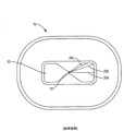
射出成形物品は、種々の目的で使用される。射出成形プラスチック製品は、一般に、ポリエチレンテレフタレート(PET)又はポリプロピレン(PP)等の材料から作製される。図1に示すような(射出ゲート15の位置に関して)非対称型形状を有する物品10の場合、フローリーダー20、例えば、公称的な部分厚からの局所的な厚さの増加を利用して、金型における射出ゲート15から様々な方向への流動長さの相違を補償する。
Injection molded articles are used for various purposes. Injection molded plastic products are generally made from materials such as polyethylene terephthalate (PET) or polypropylene (PP). In the case of an
PET及びPP等のプラスチック材料は、気体(例えば、酸素、窒素等)透過性である。気体の透過が望ましくない応用分野、例えば、食品、薬品、並びに気体へ暴露すると分解するその他の物質及び製品の場合、バリア材料がプラスチック材料と一緒に共射出される。典型的には、エチルビニルアルコール(EVOH)等のバリア材料が、PET/PP材料流の内部に射出されて、成形製品中でEVOH内部層を形成する。 Plastic materials such as PET and PP are permeable to gases (eg, oxygen, nitrogen, etc.). For applications where gas permeation is undesirable, such as foods, drugs, and other materials and products that degrade upon exposure to gas, the barrier material is co-injected with the plastic material. Typically, a barrier material such as ethyl vinyl alcohol (EVOH) is injected into the PET / PP material stream to form an EVOH inner layer in the molded product.
本発明者は、このような内部層を含む非対称型共射出成形容器を、既知の非対称成形技術を使用して、例えば、フローリーダーを利用して形成することを試みたが、得られる物品は、十分な気体不透過性を示さない。本発明者は、従来のフローリーダー技術を使用した場合、内部層が、有害な気体透過を防止するほど十分には成形製品中に延在しないことを見出した。物品のほんの小さな区域がバリア材料又は十分に厚いバリア材料を含まない場合でさえも、かなりの透過が起こる。 The inventor has attempted to form an asymmetric co-injection molded container including such an inner layer using a known asymmetric molding technique, for example, using a flow reader. It does not show sufficient gas impermeability. The inventor has found that when using conventional flow reader technology, the inner layer does not extend into the molded product sufficiently to prevent harmful gas permeation. Considerable permeation occurs even if only a small area of the article does not contain barrier material or a sufficiently thick barrier material.
本明細書中で教示される実施形態は、従来のフローリーダー技術を含む既知の非対称成形技術に関する前述の不都合と取り組む。本明細書中で教示される例示的な金型及び装置は、非対称型プラスチック成形物品をその内部材料層による優れたカバー範囲(coverage)を伴って製造するための共射出成形法において使用できる、改善されたフローリーダー技術を特色とする。本明細書中で教示されるのは、物品のシールされる又はシール可能な部分内の全表面積の95%〜100%にわたって延在するバリアカバー範囲を有する非対称型プラスチック成形物品をもたらす方式で内部コアの材料を流動させるための、例示的な金型、装置、方法、及び非一時的なコンピュータ可読プログラムである。本明細書中で教示される例示的な金型、装置、方法、及び非一時的なコンピュータ可読プログラムは、物品のシールされる又はシール可能な部分内の全表面積の99%〜100%にわたって延在するバリアカバー範囲を有する対称型プラスチック成形物品及び非対称型プラスチック成形物品を形成する際に使用するのに十分に適している。一部の例示的な物品としては、ヒートシール方法論を使用してシールすることのできる開放端を有する容器が挙げられる。 The embodiments taught herein address the aforementioned disadvantages associated with known asymmetric molding techniques including conventional flow leader technology. The exemplary molds and apparatus taught herein can be used in a co-injection molding process to produce an asymmetric plastic molded article with excellent coverage by its inner material layer. Featuring improved flow leader technology. What is taught herein is an interior in a manner that results in an asymmetric plastic molded article having a barrier coverage that extends over 95% to 100% of the total surface area within the sealed or sealable portion of the article. 2 is an exemplary mold, apparatus, method, and non-transitory computer readable program for flowing core material. The exemplary molds, apparatus, methods, and non-transitory computer readable programs taught herein extend over 99% to 100% of the total surface area within the sealed or sealable portion of the article. It is well suited for use in forming symmetric and asymmetric plastic molded articles having existing barrier coverage. Some exemplary articles include containers having open ends that can be sealed using heat sealing methodologies.
一態様において、射出成形物品を成形するための金型は、該金型キャビティの非対称部分中に少なくとも1つのフローリーダーを含む金型キャビティを備える。少なくとも1つのフローリーダーは、金型キャビティの非対称部分中の様々な厚さ及び/又は構成を画定する複数のフローリーダーからなる。多層流は、内側層、外側層、及び内部層からなる。少なくとも1つのフローリーダーは、キャビティの非対称部分の下流の多層流中に対称的な流動境界線をもたらす。 In one aspect, a mold for molding an injection molded article comprises a mold cavity that includes at least one flow leader in an asymmetric portion of the mold cavity. The at least one flow leader comprises a plurality of flow leaders that define various thicknesses and / or configurations in the asymmetric portion of the mold cavity. A multilayer flow consists of an inner layer, an outer layer, and an inner layer. At least one flow leader provides a symmetric flow boundary in the multilayer flow downstream of the asymmetric part of the cavity.
別の態様において、共射出成形装置は、金型及び第1射出ゲートを備える。金型は、非対称部分に少なくとも1つのフローリーダーを有する金型キャビティを画定する。第1射出ゲートは、流動性のある少なくとも1種の第1及び第2材料を金型キャビティ中に、しかも少なくとも1つのフローリーダーを通って共射出するように構成される。少なくとも1つのフローリーダーは、キャビティの非対称部分の下流に対称的な流動境界線をもたらすように構成される。装置は、それによって、流動性のある第1及び第2材料を含む成形物品を形成する。流動性のある第2材料は、物品中の流動性のある第1材料に対して内部に存在する。金型中の少なくとも1つのフローリーダー、及び生じる対称的な流動境界線により、装置は、物品の全表面積の95%を超えて内部に包埋された内部層を備えたプラスチック成型物品をもたらすことができる。上述の態様において、装置は、64個以上の金型キャビティを画定することができる。 In another aspect, the co-injection molding apparatus includes a mold and a first injection gate. The mold defines a mold cavity having at least one flow leader in the asymmetric portion. The first injection gate is configured to co-inject at least one flowable first and second material into the mold cavity and through at least one flow leader. At least one flow leader is configured to provide a symmetric flow boundary downstream of the asymmetric portion of the cavity. The device thereby forms a molded article that includes the flowable first and second materials. The flowable second material is present inside the flowable first material in the article. With at least one flow leader in the mold and the resulting symmetric flow boundary, the device will yield a plastic molded article with an internal layer embedded within more than 95% of the total surface area of the article Can do. In the embodiments described above, the device can define 64 or more mold cavities.
別の態様において、共射出成形装置は、複数の射出ゲート、及び複数の開放容器からなる成形物品を形成するように構成された金型キャビティを画定する金型を備える。金型キャビティは、複数の射出ゲートに関して非対称的である非対称部分、及び該非対称部分に少なくとも1つのフローリーダーを備える。複数の射出ゲートは、流動性のある第1材料及び流動性のある第2材料を金型キャビティ中に、しかも少なくとも1つのフローリーダーを通して共射出して、流動性のある第1及び第2材料を用いて成形物品を形成するように構成される。流動性のある第2材料は、流動性のある第1材料に対して内部に存在する。少なくとも1つのフローリーダーは、非対称部分の下流の流動性のある第1及び第2材料中に対称的な流動境界線をもたらすように構成される。上述の態様において、複数の開放容器は、32個の開放容器、64個の開放容器、32〜64個の間の数の開放容器、又は64個を超える開放容器を包含することができる。 In another aspect, a co-injection molding apparatus includes a mold defining a mold cavity configured to form a molded article comprising a plurality of injection gates and a plurality of open containers. The mold cavity includes an asymmetric portion that is asymmetric with respect to the plurality of injection gates, and at least one flow leader in the asymmetric portion. The plurality of injection gates co-inject the flowable first material and the flowable second material into the mold cavity and through at least one flow leader to provide the flowable first and second materials. To form a molded article. The flowable second material is present inside the flowable first material. The at least one flow leader is configured to provide a symmetric flow boundary in the flowable first and second materials downstream of the asymmetric portion. In the embodiments described above, the plurality of open containers can include 32 open containers, 64 open containers, a number between 32 and 64 open containers, or more than 64 open containers.
別の態様において、多層物品を成形する方法は、流動性のある少なくとも1種の第1材料を、流動性のある少なくとも1種の第1材料から成形物品を形成するように構成された金型キャビティ中に射出することを含む。金型キャビティは、流動性のある少なくとも1種の第1材料の射出位置に関して非対称型部分を含む。該方法は、さらに、流動性のある少なくとも1種の第2材料を金型キャビティ中に、しかも流動性のある少なくとも1種の第1材料に対して内部に共射出することを含む。該方法は、さらに、流動性のある少なくとも1種の第1材料及び流動性のある少なくとも1種の第2材料の流動を金型キャビティの非対称部分中の少なくとも1つのフローリーダーで修正して、非対称部分の下流に対称的な流動境界線をもたらし、流動性のある少なくとも1種の第2材料を、金型キャビティの実質的に全体にわたって流動させることを含む。 In another aspect, a method of forming a multilayer article includes a mold configured to form a molded article from at least one first material that is flowable and at least one first material that is flowable. Including injecting into the cavity. The mold cavity includes an asymmetric part with respect to the injection position of the at least one first material that is flowable. The method further includes co-injecting the flowable at least one second material into the mold cavity and into the flowable at least one first material. The method further includes modifying the flow of the flowable at least one first material and the flowable at least one second material with at least one flow leader in the asymmetric portion of the mold cavity; Providing a symmetric flow boundary downstream of the asymmetric portion and causing the flowable at least one second material to flow substantially throughout the mold cavity.
別の態様において、非一時的なコンピュータ可読媒体は、コンピュータが実行可能な、非対称型多層物品を成形するための命令を保持する。媒体は、流動性のある少なくとも1種の第1材料を、流動性のある少なくとも1種の第1材料から成形物品を形成するように構成された金型キャビティ中に射出するための命令を含む。金型キャビティは、流動性のある少なくとも1種の第1材料の射出位置に関して非対称型部分、及び該非対称部分に少なくとも1つのフローリーダーを備える。媒体は、さらに、流動性のある少なくとも1種の第2材料を、金型キャビティ中に、しかも流動性のある少なくとも1種の第1材料に対して内部に共射出するための命令を含む。媒体は、さらに、流動性のある少なくとも1種の第2材料の金型キャビティ中への共射出を、非対称部分の下流の少なくとも1つのフローリーダーによって修正されるような流動中に対称的な流動境界線をもたらし、流動性のある少なくとも1種の第2材料を金型キャビティの実質的に全体にわたって流動させるように計算された時間差で、流動性のある少なくとも1種の第1材料の最初の射出の後に遅延させるための命令を含む。 In another aspect, a non-transitory computer readable medium retains instructions for forming an asymmetric multilayer article that is computer executable. The medium includes instructions for injecting the flowable at least one first material into a mold cavity configured to form a molded article from the flowable at least one first material. . The mold cavity comprises an asymmetric part with respect to the injection position of the at least one first material that is flowable, and at least one flow leader in the asymmetric part. The medium further includes instructions for co-injecting the flowable at least one second material into the mold cavity and into the flowable at least one first material. The medium further flows symmetrically during flow such that the co-injection of the flowable at least one second material into the mold cavity is modified by at least one flow leader downstream of the asymmetric part. A time difference calculated to provide a boundary line and cause the flowable at least one second material to flow substantially throughout the mold cavity, and the first of the flowable at least one first material Includes instructions for delaying after injection.
上述のいずれの態様においても、少なくとも1つの射出ゲートは、金型キャビティの非対称部分に近接していても、それから遠く離れていてもよい。 In any of the embodiments described above, the at least one injection gate may be close to or far from the asymmetric portion of the mold cavity.
上述のいずれの態様においも、金型キャビティの非対称部分中の少なくとも1つのフローリーダーは、可変厚フローリーダーを含むことができる。可変厚フローリーダーは、第1流路に沿った第1厚さ、及び第2流路に沿った第2厚さを特徴とすることができる。可変厚フローリーダーは、さらに、第1厚さから第2厚さへのなめらかな移行を特徴とすることができる。移行は、射出位置から共通の距離で測定することができる。別法として、移行は、射出位置を横切る第2ラインに垂直である第1ラインに沿って測定することができる。上述のいずれの態様においても、フローリーダーを、フローリーダー中に射出された成形材料の流動先端が、第1及び第2流路の遠位端を実質的に同時に出ていくように構成することができる。 In any of the embodiments described above, the at least one flow leader in the asymmetric portion of the mold cavity can include a variable thickness flow leader. The variable thickness flow leader can be characterized by a first thickness along the first flow path and a second thickness along the second flow path. The variable thickness flow leader can further be characterized by a smooth transition from the first thickness to the second thickness. The transition can be measured at a common distance from the injection position. Alternatively, the transition can be measured along a first line that is perpendicular to a second line across the injection location. In any of the above-described embodiments, the flow leader is configured such that the flow tip of the molding material injected into the flow leader exits the distal ends of the first and second flow paths substantially simultaneously. Can do.
上述のいずれの態様においても、少なくとも1つのフローリーダーは、金型キャビティの非対称部分中に異なる厚さ及び/又は構成を画定する複数のフローリーダーを含むことができる。上述のいずれの態様の非対称部分中の複数のフローリーダーも、隣接フローリーダーの流路長と約15%を超えない、約5%を超えない、又はその間のパーセンテージを超えない差で相違する流路長を有することができる。上述のいずれの態様においても、フローリーダーを、該フローリーダー中に射出された成形材料の流動先端が、フローリーダーの遠位端を実質的に同時に出ていくように構成することができる。上述のいずれの態様においても、フローリーダーを、成形材料の流動先端が、フローリーダーの遠位端を実質的に同一流速で出ていくように構成することができる。 In any of the above aspects, the at least one flow leader can include a plurality of flow leaders that define different thicknesses and / or configurations in the asymmetric portion of the mold cavity. The plurality of flow leaders in the asymmetric portion of any of the above embodiments also differ in flow rate by no more than about 15%, no more than about 5%, or no more than a percentage therebetween, with the flow length of the adjacent flow leader. Can have a path length. In any of the aspects described above, the flow leader can be configured such that the flow tip of the molding material injected into the flow leader exits the distal end of the flow leader substantially simultaneously. In any of the aspects described above, the flow leader can be configured such that the flow tip of the molding material exits the distal end of the flow leader at substantially the same flow rate.
上述のいずれの態様においても、少なくとも1つのフローリーダーを、少なくとも1つのフローリーダーの遠位端を出ていく内部層のリーディングエッジの速度が、複合流の先端速度に内部層のリーディングエッジから金型の外縁までの流動距離を複合流の先端から金型の外縁までの流動距離で除した商を乗算した積に実質的に等しい、及び/又はそれより大きいように構成することができる。上述のいずれの態様においても、金型キャビティの非対称部分中の少なくとも1つのフローリーダーを、下流に対称的な流動境界線をもたらすように構成することができる。フローリーダーを、均一な又は均一でない対称的な流動境界線をもたらすように構成することができる。 In any of the embodiments described above, the speed of the leading edge of the inner layer exiting the distal end of the at least one flow leader is reduced from the leading edge of the inner layer to the tip speed of the composite flow. The flow distance to the outer edge of the mold can be configured to be substantially equal to and / or greater than the product of the quotient divided by the flow distance from the leading edge of the composite flow to the outer edge of the mold. In any of the embodiments described above, at least one flow leader in the asymmetric portion of the mold cavity can be configured to provide a symmetric flow boundary downstream. The flow leader can be configured to provide a uniform or non-uniform symmetric flow boundary.
上述のいずれの態様においても、第1材料と第2材料との複合流を、金型キャビティの非対称部分中で少なくとも1つのフローリーダーによって修正することができる。上述のいずれの態様においても、第2材料の流動開始を、ある時間差で第1材料の流動開始後に遅延させることができる。遅延時間は、少なくとも1つのフローリーダーによって修正されるような下流の流動中に、対称的な流動境界線をもたらし、且つ第2材料を金型キャビティの実質的に全体にわたって流動させるように計算することができる。 In any of the embodiments described above, the composite flow of the first material and the second material can be modified by at least one flow leader in the asymmetric portion of the mold cavity. In any of the above-described embodiments, the start of flow of the second material can be delayed after the start of flow of the first material by a certain time difference. The delay time is calculated to provide a symmetric flow boundary during downstream flow as modified by at least one flow leader, and to cause the second material to flow substantially throughout the mold cavity. be able to.
別の態様において、多層射出成形物品は、成形物品の構成を全体的に画定する少なくとも1種の第1材料を含む。成形物品は、射出成形中に第1材料の射出位置に関して非対称型部分を含む。射出成形物品は、さらに、少なくとも1種の第1材料の内部に実質的に含められ、成形物品の全体の95%超にわたって延在する少なくとも1種の第2材料を含む。成形物品の非対称部分中の通路長(その通路に沿って、少なくとも1種の第1及び少なくとも1種の第2材料が流動して成形物品を形成する)は、任意の隣接通路の長さと約15%超えない差で相違する。 In another embodiment, the multilayer injection molded article includes at least one first material that generally defines the configuration of the molded article. The molded article includes an asymmetric portion with respect to the injection position of the first material during injection molding. The injection molded article further includes at least one second material substantially contained within the at least one first material and extending over 95% of the total molded article. The passage length in the asymmetric part of the molded article (at least one first and at least one second material flows along the passage to form the molded article) is about the length of any adjacent passage. Differences do not exceed 15%.
別の態様において、多層射出成型物品は、少なくとも1種の第1材料及び少なくとも1種の第2材料を含む。少なくとも1種の第1材料は、成形物品の構成を全体的に画定する。成形物品は、その射出成形中に第1材料の射出位置に関して非対称型部分を含む。少なくとも1種の第2材料は、少なくとも1種の第1材料の内部に実質的に含められ、成形物品の全体の95%超にわたって延在する。成形物品の非対称部分は、第1通路に関する第1厚さ及び第2通路に関する第2厚さを特徴とする(少なくとも1種の第1材料及び少なくとも1種の第2材料は、それらの通路に沿って流動して成形物品を形成する)。成形物品の非対称部分は、第1厚さから第2厚さへのなめらかな移行を特徴とする。 In another embodiment, the multilayer injection molded article includes at least one first material and at least one second material. The at least one first material generally defines the configuration of the molded article. The molded article includes an asymmetric part with respect to the injection position of the first material during its injection molding. The at least one second material is substantially contained within the at least one first material and extends over more than 95% of the entire molded article. The asymmetric part of the molded article is characterized by a first thickness with respect to the first passage and a second thickness with respect to the second passage (at least one first material and at least one second material are in the passages). Flow along to form a molded article). The asymmetric part of the molded article is characterized by a smooth transition from the first thickness to the second thickness.
別の態様において、多層成形容器は、その外縁を画定する閉鎖端、及び閉鎖端の外縁から延在する少なくとも1つの壁を備える。少なくとも1つの壁は、閉鎖端の外縁のまわりに全体的に延在する容器側壁を画定し、さらに、閉鎖端に対向する容器の開放端を画定する。閉鎖端及び側壁は、閉鎖端上の射出位置で共射出され、且つ閉鎖端及び側壁の構成を全体的に画定する第1及び第2材料から形成される。第2材料は、第1材料の内部に実質的に含められる。閉鎖端は、射出位置に関して非対称的である。開放端を、実質的に気体不透過性の閉鎖部材(closure)で閉鎖して、シールにより容器を閉鎖することができる。閉鎖端の非対称部分の通路長(第1及び第2材料は、その通路に沿って流動して成形容器を形成する)は、任意の隣接通路の長さと15%を超えない差で相違する。容器を閉鎖部材でシールすると、閉鎖された容器中への酸素の透過は、1日につき約0.05ppm未満である。 In another aspect, the multilayer molded container comprises a closed end defining an outer edge thereof and at least one wall extending from the outer edge of the closed end. The at least one wall defines a container side wall that extends generally around the outer edge of the closed end and further defines an open end of the container opposite the closed end. The closed end and sidewall are co-injected at an injection location on the closed end and are formed from first and second materials that generally define the closed end and sidewall configuration. The second material is substantially contained within the first material. The closed end is asymmetric with respect to the injection position. The open end can be closed with a substantially gas impermeable closure and the container closed with a seal. The passage length of the asymmetric portion of the closed end (the first and second materials flow along the passage to form a molded container) differs from the length of any adjacent passage by no more than 15%. When the container is sealed with a closure member, the permeation of oxygen into the closed container is less than about 0.05 ppm per day.
別の態様において、多層成形容器は、その外縁を画定する閉鎖端、及び閉鎖端の外縁から延在する少なくとも1つの壁を備える。少なくとも1つの壁は、閉鎖端の外縁のまわりに全体的に延在する容器側壁を画定し、さらに、閉鎖端に対向する容器の開放端を画定する。閉鎖端及び側壁は、閉鎖端上の射出位置で共射出され、且つ閉鎖端及び側壁の構成を全体的に画定する第1及び第2材料から形成される。第2材料は、第1材料の内部に実質的含められる。閉鎖端は、射出位置に関して非対称的である。開放端を、実質的に気体不透過性の閉鎖部材で閉鎖して、シールにより容器を閉鎖することができる。閉鎖端の非対称部分は、第1通路に関する第1厚さ及び第2通路に関する第2厚さを特徴とする(第1及び第2材料は、その通路に沿って流動して成形容器を形成する)。閉鎖端の非対称部分は、第1厚さから第2厚さへのなめらかな移行を特徴とする。容器を前記閉鎖部材でシールすると、閉鎖された容器中への酸素の透過は、1日につき約0.05ppm未満である。 In another aspect, the multilayer molded container comprises a closed end defining an outer edge thereof and at least one wall extending from the outer edge of the closed end. The at least one wall defines a container side wall that extends generally around the outer edge of the closed end and further defines an open end of the container opposite the closed end. The closed end and sidewall are co-injected at an injection location on the closed end and are formed from first and second materials that generally define the closed end and sidewall configuration. The second material is substantially contained within the first material. The closed end is asymmetric with respect to the injection position. The open end can be closed with a substantially gas impermeable closure and the container can be closed with a seal. The asymmetric part of the closed end is characterized by a first thickness with respect to the first passage and a second thickness with respect to the second passage (the first and second materials flow along the passage to form a molded container ). The asymmetric part of the closed end is characterized by a smooth transition from the first thickness to the second thickness. When the container is sealed with the closure member, the permeation of oxygen into the closed container is less than about 0.05 ppm per day.
上述のいずれの成形物品又は容器の部分も、上記の少なくとも1つのフローリーダー(複数可)に対応する。上述のいずれの成形物品又は容器においても、第2材料を、第1材料の内部で折り返すことができる。任意の上述の容器が前記閉鎖部材でシールされる場合、閉鎖された容器中への酸素の透過は、1日につき約0.05ppm未満であり得る。 Any molded article or container portion described above corresponds to the at least one flow leader (s) described above. In any of the molded articles or containers described above, the second material can be folded inside the first material. If any of the above containers are sealed with the closure member, the permeation of oxygen into the closed container may be less than about 0.05 ppm per day.
上述のいずれの態様においても、内側及び外側層を形成する第1材料は、内部層を形成する第2材料と異なる材料でよい。上述のいずれの態様においても、内側及び外側層(複数可)を形成する第1材料は、射出成形に適したポリエチレン又はポリプロピレン等のプラスチック系材料でよい。上述の態様のいずれにおいても、第2材料は、内側層及び外側層の内部に実質的に含められるか包埋される。上述のいずれの態様においても、第2材料は、第1材料に比べて相対的により酸素不透過性である材料でよい。上述のいずれの態様においても、第2材料は、内側層及び外側層を形成する第1材料に比較して、気体、光、UV線、及び/又は電磁波に対して高められた不透過性を示す材料及び/又は組成物でよい。上述のいずれの態様においても、第2材料は、エチルビニルアルコール、ナイロン、酸素捕捉材料、及び/又は乾燥剤を含むことができる。上述のいずれの態様においても、非対称部分を有する共成形物品の内部層は、内側層及び外側層にわたって(例えば、間に)、既知の物品に比べてより大きな度合まで延在することができる。上述のいずれの態様においても、第1材料及び/又は第2材料は、接着剤を含むことができる。 In any of the above embodiments, the first material forming the inner and outer layers may be a material different from the second material forming the inner layer. In any of the above embodiments, the first material forming the inner and outer layer (s) may be a plastic material such as polyethylene or polypropylene suitable for injection molding. In any of the above aspects, the second material is substantially contained or embedded within the inner and outer layers. In any of the embodiments described above, the second material may be a material that is relatively more oxygen-impermeable than the first material. In any of the embodiments described above, the second material has an increased impermeability to gas, light, UV radiation, and / or electromagnetic waves compared to the first material forming the inner and outer layers. It may be the indicated material and / or composition. In any of the above aspects, the second material can include ethyl vinyl alcohol, nylon, oxygen scavenging material, and / or desiccant. In any of the aspects described above, the inner layer of a co-molded article having an asymmetric portion can extend to a greater degree than known articles across (eg, between) the inner and outer layers. In any of the above-described aspects, the first material and / or the second material can include an adhesive.
本明細書中で教示されるコンピュータ化された例示的なシステム、方法、及び非一時的なコンピュータ可読記憶媒体は、材料の内部コアが、透過に暴露される全表面積の95%を超える範囲内に、例えば、物品のシールされる又はシール可能な部分の範囲内に包埋されたバリアカバー範囲を備えた非対称型プラスチック成型物品をもたらす方式で流動するように構成及び改作される。本明細書中で教示されるコンピュータ化されたシステム、方法、及び非一時的なコンピュータ可読記憶媒体は、さらに、材料の内部コアが、透過に暴露される全表面積の95%を超える範囲内に包埋されたバリアカバー範囲を備えた非対称型プラスチック成型物品をもたらす方式で流動するように構成及び改作される。一部の実施形態において、コンピュータが実施可能な命令を保持するコンピュータが読み取り可能な記憶媒体が教示される。プロセッサによる命令の実行は、本明細書で教示されるような多層共成形物品の形成を制御する。プロセッサによる命令の実行は、厚さ及び構成を異にしてもよい複数のフローリーダーを有する非対称金型キャビティ中での複合材料流中への内部層材料の射出を制御し、射出を引き起こす。内部層材料は、生じる多層成形物品中にバリア層又は捕捉剤層を形成する。プロセッサによって例示的な命令を実行すると、生じる多層成形物品は、高いカバー範囲を備えて形成される。 The computerized exemplary systems, methods, and non-transitory computer readable storage media taught herein are such that the inner core of the material is in a range that exceeds 95% of the total surface area exposed to permeation. For example, it is constructed and adapted to flow in a manner that results in an asymmetric plastic molded article having a barrier cover area embedded within the sealed or sealable portion of the article. The computerized systems, methods, and non-transitory computer readable storage media taught herein further provide that the inner core of the material is within a range that exceeds 95% of the total surface area exposed to permeation. Constructed and adapted to flow in a manner that results in an asymmetric plastic molded article with an embedded barrier cover area. In some embodiments, a computer-readable storage medium is taught that retains computer-executable instructions. Execution of instructions by the processor controls the formation of multilayer co-molded articles as taught herein. Execution of instructions by the processor controls injection of the inner layer material into the composite flow in the asymmetric mold cavity having a plurality of flow leaders that may be of different thicknesses and configurations. The inner layer material forms a barrier layer or scavenger layer in the resulting multilayer molded article. When the exemplary instructions are executed by the processor, the resulting multilayer molded article is formed with a high coverage.
本発明のその他の目的及び利点は、実施形態に関する次の詳細な説明及び添付の図面から明らかになるであろう。 Other objects and advantages of the present invention will become apparent from the following detailed description of the embodiments and the accompanying drawings.
図2は、共射出プラスチック成形製品の壁を通過する酸素透過を、製品のシールされる部分の被暴露壁の全表面積に対する内部バリアのカバー範囲の関数として表した酸素透過曲線50を概略的に図示している。図2は、また、シールされた容器内での物質の望ましくない分解を防止するための透過上限を表す目標透過速度60を図示している。図2のグラフと関連する内部層材料は、エチルビニルアルコール(EVOH)、MXD6ナイロン、又はその他の受動バリア材料からなることができ;EVOH、MXD6ナイロン、又はその他のバリア材料のいずれも酸素捕捉成分を有し、EVOH、MXD6ナイロン、又はその他のバリア材料のいずれも乾燥成分を有する。図2からわかるように、例示実施形態において、0.005ppmO2/日/容器(ppmは、容器中の液状内容物に基づいて計算される)である目標透過速度60を達成するには、99%を超えるカバー範囲が要求される。目標透過速度60は、容器内の個々の物質、容器の構成、及び所望される貯蔵寿命に依存するが(全透過は、双方向の速度、被暴露面積、及び時間の関数である)、本発明者は、示した目標透過速度60は食物を含む物品に関して典型的であると考える。さらに、透過速度は、また、暴露条件、及び若干程度は容器の壁厚に依存するが、食物貯蔵技術分野の当業者は、透過曲線50は、好ましくはないが典型的な貯蔵条件下の食物用容器に関して典型的であると考える。試験パラメーターの予想される変動は、類似の結果をもたらした。
FIG. 2 schematically shows an
食物及び所望の所蔵時間(貯蔵寿命)に応じて、目標透過速度60は、0.005ppm O2/日/容器に比べてより大きい又はより小さい桁の大きさ、すなわち0.05又は0.0005ppm O2/日/容器でよい。透過曲線50の勾配は、内部層材料の様々な種類及び厚さによって異なるが、当業者は、容器表面積のバリアカバー範囲のそれぞれ1%の減少で、透過速度のかなりの増加が起こることを認識するであろう。
Depending on the food and the desired holding time (shelf life), the target permeation rate 60 is larger or smaller orders of magnitude compared to 0.005 ppm O 2 / day / container, ie 0.05 or 0.0005 ppm O 2 / day / Can be a container. Although the slope of the
図3Aは、本明細書中で教示される実施形態により目標透過速度を達成する容器100を示す。容器100は、底部105、チャンバー106を形成するために底部105の外縁から延在する側壁110を有し、この実施形態において、チャンバーは、一般に、カップ形状又はU字形状であり、開放端107、及び容器の開放端107で側壁110の外縁から延在するフランジ115を有する。図示した実施形態において、側壁110は、4つの丸みを帯びた曲がり角部分112、及び曲がり角部分112の間に延在する4つの直線部分113を有する。図3Aは、曲がり角部分112a及び112b並びに直線部分113a及び113bを図示する。しかし、容器100は、その意図した用途に所望されるように構成されることができ、この目的に、例えば所望の物質を入れるのに適した寸法及び構造的完全性を有する。当業者は、これを達成する方法を理解しているであろう。
FIG. 3A shows a
容器100は、さらに、シール可能な表面を備えたシーリングゾーン120を含むことができる。図3Aに図示した実施形態において、シーリングゾーン120及びその表面は、フランジ115中に形成され、フランジ115の周囲を周回的に延在する。シーリングゾーン120の表面は、フランジ115の実質的に全体にわたって周回的に延在することができる。しかし、図3Aの実施形態において、シーリングゾーン120の表面は、フランジ115の内側部分のみを含む。シーリングゾーン120及びその表面は、天板(top)又は蓋等の取り外し可能な又は取り外しできない閉鎖部材(closure)(図示せず)に係合し、チャンバー106の開放端107を部分的又は完全に閉鎖するのに使用することができる。閉鎖部材それ自体は、実質的に気体不透過性でよい。この方式では、チャンバー106の開放端107を閉鎖して両方が容器の内容物を維持し、例えば、流動性物質を容器内に保持し、且つ望ましくない気体透過を防止することができる。
The
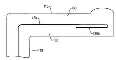
容器100は、既知であるような製造要件(例えば、熱膨張/収縮)を考慮して、例えばPET又はPP等のプラスチック系材料を金型キャビティ中に、内側層130及び外側層132(これらは、一緒になって、全体として容器又は製品の所望の最終形状になる)を形成するように射出することによって形成することができる。本明細書中で「内側」又は「外側」層と称され、図示した実施形態において、内側層130及び外側層132は、容器のそれぞれ内側及び外側を形成するにもかかわらず、それらの用語は、そのような使い方に限定されるとは解釈されない。むしろ、該用語は、単に、成形製品の壁又は「スキン」を形成するプラスチック系材料の部分を指す。外側層132及び内側層130の材料(複数可)は、当業者にとって公知であるように、位置140の射出ゲートを通って射出される。PET及びPPは通常的に使用される材料であるが、高密度ポリエチレン(HDPE)又はポリカーボネート(PC)等のその他の適切な材料も使用できること、及び様々な実施形態はその他のポリマー材料を使用できることを理解されたい。
The
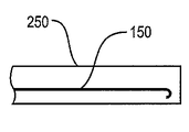
図3Bは、図3Aの容器100の、図3A中で指示した線に沿った断面を示す。しかし、図3Bにおいて、容器の壁厚は、構造を説明するために誇張してある。図3Bからわかるように、容器100は、容器の実質的に全体にわたって延在するが、外側層132及び内側層130によって実質的に完全に囲まれた内部コア層150を有する。内部層150は、EVOH、ナイロン、MXD6ナイロン、酸素捕捉材料、乾燥剤、或いは気体例えば酸素が容器を通って、すなわち外側から内側へ、及びその逆で透過するのを十分に防止することが知られている又は知られるようになる可能性のあるその他の適切な材料等のバリア材料である。同様に、層150のバリア材料は、光、UV線、及び/又は電磁波が容器を通って透過するのを防止することができる。目標気体透過速度が小さい実施形態、例えば、酸素に対して高度に敏感な食品又はその他の材料のための容器では、内部層150は、容器100の被暴露表面の約99%以上に沿って延在することができる。一部の実施形態において、被暴露表面は、シール区域120の外縁内に存在するように画定された表面である。シール区域120は、シール材が接触して容器の開放端107をシールする、外側の表面、ゾーン、又は領域である。一部の実施形態において、被暴露表面は、シール接触表面120の外縁を超えて延在するように画定された表面である。
FIG. 3B shows a cross-section of the
図2に示すように、内部層150によるこの高いカバー範囲は、予想される典型的な暴露条件中で、99%未満のカバー範囲と比較して気体透過を劇的に低減する。図3Bの特定の実施形態でわかるように、内部層150は、フランジ115中に延在する。この実施形態において、フランジ、及びそのためフランジ中の内部層150の一部は、容器の側壁110に対してある角度をなして、この場合、ほぼ直角で存在するが、フランジ中の内部層150の一部は、容器の被暴露区域に関するカバー範囲にほとんど寄与しない。他の実施形態において、容器及びフランジの構成に応じて、高い度合(例えば99%以上)のカバー範囲を含む所望の度合のカバー範囲を、フランジ115中に、又は有意にフランジ115中に延在する内部層150なしで得ることができる。さらに他の実施形態は、フランジ(又はその一部)が、気体がそれを通ってチャンバー106の中に又はチャンバーの外に透過できる被暴露区域を提供できる、フランジ構成を有することができる。このような実施形態において、内部層150は、フランジ115中に延在して、所望の度合のカバー範囲を提供することができる。さらに、開放端107が蓋又は閉鎖部材、例えばヒートシールによってシールされる実施形態において、内部層150は、十分な透過バリアを提供するのにシールを超えて延在する必要がない場合もある。
As shown in FIG. 2, this high coverage by the
例を挙げれば、図4は、チャンバー106の開放端107を閉鎖する閉鎖部材125を有する容器100の別の実施形態を図示する。閉鎖部材125それ自体は、例えばホイル材料によって、典型的には実質的に気体不透過性である。例えば、食品用容器で使用するために一般的に知られ使用される蓋は、ヒートシールされる蓋である。このような蓋は、ホイル層、例えばアルミニウムホイルを含むことができ、シーリングゾーン120の表面区域内でフランジ115に接触するホイル層の少なくとも一部の上にプラスチック層の被覆を有する。プラスチック層は、典型的には、容器100と同一(又は類似の)材料である。閉鎖部材125をフランジ115に、シール接触表面120で、従来方法によって、例えばヒートシール、襞付け(crimping)、及びその他の公知の方法によってシールすることができる。従来のシール方法は、シーリングゾーン120の表面区域に閉鎖部材をシールするために、プラスチック層及び/又は隣接フランジ115材料を十分に軟化及び/又は融解させる熱及び加圧を必要とすることが多い。
By way of example, FIG. 4 illustrates another embodiment of a
気付くように、内部層150は、フランジの端部まで延在していない。しかし、当業者は、内部層を含まないフランジの被暴露部分が、容器100の被暴露全表面区域の極度に小さな部分であることを認識するはずである(図4中のフランジ115の厚さは、説明の目的で大きく誇張されている)。したがって、内部層150がフランジ115の外側外縁まで延在していることなしに、高度のカバー範囲の度合(例えば、99%以上)を含む所望のカバー範囲の度合を得ることができるが、一部の実施形態において、内部層は、フランジ115の外側外縁まで延在していてもよい。別の方式で、カバー範囲の度合は、閉鎖部材125が容器にシールされる位置、例えば、シール接触表面120の範囲内に存在する、シールされる又はシール可能な容器100の部分に最も関連する。十分な度合のカバー範囲が、シール接触表面、ゾーン又は領域の外側境界によって画定される区域内で、例えば、シール接触表面の範囲内で99%のカバー範囲で達成されるなら、所望の透過速度を達成することができる。図示した実施形態において、例えば、内部層150は、シール接触表面のマージンまで又はそれを超えて(この容器の構成では、マージンの内側に向かって放射状に)延在しており、その箇所を超えて内部層が延在することなしに、十分なカバー範囲が得られる。それにもかかわらず、実施形態を利用して、図2において点線で図示したように、内部層150を、シール接触面のマージンを超えてフランジの端部又はその近くまで準備することができる。
As will be noted, the
図示した実施形態は、カップ様形状を有するが、本発明は、シーリングゾーン120を使用して容器の一部をシールすることができる別の形状又は構成を有する、当業者によって認識されて当然である容器を想定している。例えば、側壁110がリップ(lip)を有するなら、そのリップは、代わりに、シーリングゾーン及びその表面を含むことができる。さらに、図4の実施形態は、閉鎖部材125によって閉じることのできる開放端107を有するが、異なる開放端を有する代わりの実施形態も想定される。図4の実施形態において、成形物品のシール可能な部分の表面区域は、基体105の表面区域、側壁110の表面区域、及び閉鎖部材125のシーリングゾーン120下に放射状に延在するフランジ115の一部の表面区域を含む。代わりの成形物品のシール可能部分の表面区域は、それらの形状又は構成、及びそれらがシールされる又はシールされることを意図した場所に応じて、様々に画定することができる。例えば、代わりの容器の実施形態のシール可能部分の表面区域は、フランジまで延在していなくてもよいが、代わりに、例えば、側壁のリップ中のシーリングゾーンまでだけに延在していてもよい。
While the illustrated embodiment has a cup-like shape, it should be recognized by those skilled in the art that the present invention has other shapes or configurations that can seal portions of the container using the
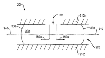
図5Aに概略的に示すように、金型200は、金型部分210a、210bを有し、それらの間に金型キャビティ220が形成される。材料は、ノズルアセンブリから射出位置140の射出ゲートを通って、金型キャビティ220中に射出される。ノズルアセンブリは、内側材料、外側材料、及び内部材料から複合流300を形成する。該複合流300(特定の構成では、環状流でもよい)は、射出位置140から金型キャビティ220中に流れる。内側材料は、複合流300の内側流を形成し、内部材料は内部流150aを形成し、外側材料は外側流を形成する。複合流300は、金型キャビティ220中を移動する流動先端330を形成する。特定の時点で、複合流300は、2種の材料(内側及び外側)又は3種の材料(内側、外側及び内部)からなることができる。
As schematically shown in FIG. 5A, the
内部材料の流れは、図5A中で150aとして示されている。外側層132及び内側層130の材料流の内部に内部層材料150を同時に射出することによって、成形物品中に内部層150を作り出すことができる。このような方法は、一般に公知であり、参照によりその全体が本明細書に組み込まれる、例えば、米国特許第6,908,581号及びその中に組み込まれている文献中に記載されている。
The internal material flow is shown as 150a in FIG. 5A. By simultaneously injecting the
図5Aと同様、図5Bは、金型部分210a、210bを有し、それらの間に金型キャビティ220を形成する金型200を概略的に示す。以下でさらに詳細に考察するように、複合流300を形成する内側流と外側流との体積流量比率は、内部層流の流れが複合流300のゼロ速度勾配340(Vmax)からずれた流線に沿って、しかも複合流300の平均流速(Vave)に比べてより大きな速度を有する流線上を流れるように選択される。このことは、内部層材料の流れ150aが、流動先端330を突き抜ける(breaking through)のを防止する。むしろ、図5Bに示すように、内部層のリーディングエッジが複合流の先端330の直前に接近すると、内部層材料流150aは、折り返って流動先端330の背後に折り返し部分150bを形成し、複合流300の内側流及び外側流によって包まれたままである。内部層材料流150aをゼロ速度勾配からずらして出発させることによって、内部層は、流動先端に「追いつく」ことができ、ファウンテンフロー(fountain flow)及び折り返しを形成することができる。このことが、生じるプラスチック成形物品の99%〜100%のカバー範囲にわたって延在し、且つバリア又は捕捉剤による保護を提供できるバリア層又は捕捉層を形成する。内部層は、その部分の内側又は外側に向かって折り返しを作り出すゼロ速度勾配の位置の内側又は外側に配置することができる。
Similar to FIG. 5A, FIG. 5B schematically illustrates a
再び図3Aを参照して、容器の底部105は、射出ゲートの位置140aの位置の周りで対称でない。すなわち、射出ゲートの位置140aと底部105の外縁との間の距離は、底部105の外縁の周りで異なる。この実施形態において、この距離は、射出ゲートの位置140aから側壁の直線部分113aに垂直な流路に沿って最短であり、側壁の曲がり角部分112に垂直な流路に沿った最長まで増加し、側壁の直線部分113bに垂直な流路に沿ったもう1つの最短まで減少する。図3Aの実施形態において、容器100は、一般に、長方形の形状を有するので、射出位置140aから側壁の直線部分113bに垂直な流路の長さは、射出位置140aから側壁の直線部分113aに垂直な流路の長さに比べてより長い。しかし、当業者は、いずれの軸非対称形状も、異なる流路長をもたらすことを理解するであろう。
Referring again to FIG. 3A, the
異なる流路長を補償するために、一般にはより長い流路の方向に延在する均一なより大きな厚さの金型キャビティ部分からなるフローリーダーを有する金型キャビティを利用することが知られている。しかし、本発明者は、このようなフローリーダーを使用することは、単層(単一材料)物品を製造するには十分であるが、望ましくない気体透過を防止するための内部層による十分なカバー範囲を有する多層(複数材料)物品をもたらさないことを見出した。本発明者は、このようなフローリーダーを使用してさえも、外側層材料の流れは、全般的な流動方向に対して横方向に流れ、内部層材料の流れを妨害し、内部層の適切な形成を妨げると立論する。したがって、既知のフローリーダー技術は、外側層材料の全般的な流れを十分に補償するが(単一材料の成形の場合のように)、これらの技術は、共射出成形で内部層材料をも使用する場合には不十分である。 In order to compensate for different flow path lengths, it is generally known to utilize a mold cavity having a flow leader consisting of a uniform larger thickness mold cavity portion extending in the direction of a longer flow path. Yes. However, while the inventor uses such a flow reader is sufficient to produce a single layer (single material) article, it is sufficient for the inner layer to prevent undesirable gas permeation. It has been found that it does not result in a multilayer (multi-material) article having a coverage. Even with the use of such a flow leader, the inventor flows the outer layer material transversely to the general flow direction, obstructing the inner layer material flow, It is argued that it will prevent proper formation. Thus, while known flow leader techniques adequately compensate for the overall flow of the outer layer material (as in the case of single-material molding), these techniques also use inner layer material in co-injection molding. When used, it is insufficient.
本発明者は、流れに対して特定の効果をもたらすように設計された少なくとも1つのフローリーダーを金型キャビティの非対称部分中で利用することによって、十分なカバー範囲を提供する内部層を有する多層物品を成形できることを発見した。本明細書中で本発明に関して使用する場合、用語「フローリーダー」は、金型キャビティの公称設計厚さと異なる厚さを有する壁部分を意味し、その壁部分は、金型キャビティの中で流れを優先的に変えるように設計される。一部の実施形態において、本明細書中で教示されるフローリーダーは、変動する壁厚を有する壁部分を含む。一部の実施形態において、本明細書中で教示されるフローリーダーは、変動する壁厚の複数のセグメントを有する壁部分を含む。一部の実施形態において、第1壁厚からより厚い又はより薄い第2壁厚への比較的なめらかな移行、例えばテーパーのついた又は傾斜した移行が存在できる。一部の実施形態において、第1膜厚からより厚い又はより薄い第2壁厚への比較的急激な移行、例えば、段階的移行が存在できる。 The inventor has developed a multilayer with an inner layer that provides sufficient coverage by utilizing in the asymmetric part of the mold cavity at least one flow leader designed to have a specific effect on the flow. Discovered that the article can be molded. As used herein with respect to the present invention, the term “flow leader” means a wall portion having a thickness that is different from the nominal design thickness of the mold cavity, the wall portion flowing in the mold cavity. Designed to change the priority. In some embodiments, the flow leader taught herein includes a wall portion having a varying wall thickness. In some embodiments, the flow leader taught herein includes a wall portion having a plurality of segments of varying wall thickness. In some embodiments, there can be a relatively smooth transition from a first wall thickness to a thicker or thinner second wall thickness, such as a tapered or sloped transition. In some embodiments, there can be a relatively abrupt transition from a first film thickness to a thicker or thinner second wall thickness, eg, a gradual transition.
フローリーダーの可変厚は、金型キャビティ中に射出され、金型キャビティの非対称部分中のフローリーダーを通過する材料(外側層材料及び内側層材料の双方並びに内部層材料を含めて)が、その下流に特定の条件を満たす流動境界線を形成するように選択することができる。可変厚フローリーダーを使用することによって、材料流を金型キャビティ中でより厳密に制御、調整し、内部層材料の改善された、より一様な流れを可能にし、より完全な内部層を形成することができる。付加的に又は代わりに、複数のフローリーダーのそれぞれの厚さは、金型キャビティ中に射出され、金型キャビティの非対称部分中の複数のフローリーダーを通過する材料(外側及び内側層材料の双方並びに内部層材料を含めて)が、その下流に特定の条件を満たす流動境界線を形成するように選択することができる。例えば、流動境界線の下流で、内側及び外側層材料並びに内部層材料は、実質的に同一時間、望ましくは実質的に同一流速(例えば、速度)で金型キャビティの外縁に到達することができる。したがって、種々の実施形態は、以前から知られているフローリーダー技術を使用する場合に比べて増加した内部層のカバー範囲を備えた共射出物品を提供することができる。それらの実施形態は、例えば、内部層による約99%を超えるカバー範囲を備えた高カバー範囲の物品を提供することができる。 The variable thickness of the flow leader is determined by the material (including both outer and inner layer materials and inner layer material) that is injected into the mold cavity and passes through the flow leader in the asymmetric part of the mold cavity. A flow boundary line that satisfies a specific condition can be selected downstream. By using a variable thickness flow reader, the material flow is more tightly controlled and regulated in the mold cavity, allowing an improved and more uniform flow of the inner layer material and forming a more complete inner layer can do. Additionally or alternatively, the thickness of each of the plurality of flow leaders is injected into the mold cavity and passes through the plurality of flow leaders in the asymmetric portion of the mold cavity (both outer and inner layer materials). As well as the inner layer material) can be selected downstream to form a flow boundary that satisfies certain conditions. For example, downstream of the flow boundary, the inner and outer layer materials and the inner layer material can reach the outer edge of the mold cavity at substantially the same time, desirably at substantially the same flow rate (e.g., speed). . Accordingly, various embodiments can provide co-injected articles with increased inner layer coverage compared to using previously known flow reader technology. Those embodiments can provide high coverage articles with, for example, greater than about 99% coverage by the inner layer.
金型キャビティの非対称部分中の少なくとも1つのフローリーダーの厚さは、金型キャビティ中に射出され、少なくとも1つのフローリーダーを通過し、且つフローリーダーの遠位端に存在する材料が金型キャビティ中で下流に対称的な流動境界線を形成するように選択することができる。同様に、金型キャビティの非対称部分中の複数のフローリーダーのそれぞれの厚さは、金型キャビティ中に射出され、複数のフローリーダーを通過し、且つフローリーダーの遠位端に存在する材料が金型キャビティ中で下流に対称的な流動境界線を形成するように選択することができる。対称的な流動境界線を通過する材料は、実質的に同一時間、望ましくは実質的に同一流速(例えば、速度)で金型キャビティの外縁に到達することができる。複数のフローリーダーを使用することによって、材料流を金型キャビティ中でより厳密に制御、調整し、より完全な内部層が形成されるように改善された内部層材料の流動を可能にする。したがって、種々の実施形態は、以前から知られているフローリーダー技術を使用する場合に比べて増加した内部層のカバー範囲を備えた共射出物品を提供することができる。それらの実施形態は、例えば、内部層による約99%を超えるカバー範囲を備えた高カバー範囲の物品を提供することができる。 The thickness of the at least one flow leader in the asymmetric part of the mold cavity is injected into the mold cavity, passes through the at least one flow leader, and the material present at the distal end of the flow leader is the mold cavity It can be selected to form a symmetric flow boundary in the downstream. Similarly, the thickness of each of the plurality of flow leaders in the asymmetric portion of the mold cavity is injected into the mold cavity, passes through the plurality of flow leaders, and the material present at the distal end of the flow leader is One can choose to form a symmetric flow boundary downstream in the mold cavity. Material passing through the symmetric flow boundary can reach the outer edge of the mold cavity at substantially the same time, preferably at substantially the same flow rate (eg, speed). By using multiple flow leaders, material flow is more tightly controlled and tuned in the mold cavity, allowing improved inner layer material flow to form a more complete inner layer. Accordingly, various embodiments can provide co-injected articles with increased inner layer coverage compared to using previously known flow reader technology. Those embodiments can provide high coverage articles with, for example, greater than about 99% coverage by the inner layer.
本明細書中で教示されるような単一又は複数のフローリーダーは、下流に対称的な流動境界線をもたらすように構成することができる。特許請求の範囲及び本明細書中で教示される実施形態に関して使用する場合、用語「対称的な流動境界線」は、その境界線の下流で、複合流の先端速度(VF)が金型の外縁に対して実質的に垂直であり、且つ内部層のリーディングエッジの速度(VI)が、複合流の先端速度に、内部層のリーディングエッジから金型の外縁までの流動距離を複合流の先端から金型の外縁までの流動距離で除算した商を乗算した積[VF×(LI/LF)]に実質的に等しい、及び/又はその積より大きい、境界線を意味する。 Single or multiple flow leaders as taught herein can be configured to provide a symmetric flow boundary downstream. As used with respect to the claims and the embodiments taught herein, the term “symmetrical flow boundary” means that the tip velocity (V F ) of the composite flow is the mold downstream of the boundary. The leading edge velocity (V I ) of the inner layer is substantially perpendicular to the outer edge of the inner layer, and the flow velocity from the leading edge of the inner layer to the outer edge of the mold is combined with the leading edge velocity of the inner layer. Means a boundary line that is substantially equal to and / or greater than the product [V F × (L I / L F )] multiplied by the quotient divided by the flow distance from the tip of the mold to the outer edge of the mold .
本明細書中で教示される実施形態による多層流に関し、金型キャビティの非対称部分中の1つ以上のフローリーダーは、その下流の金型キャビティ中に、(1)複合流の速度が、金型キャビティの外縁に対して事実上垂直であり、そのため速度ベクトルが有意な接線成分を有せず、且つ(2)内部層のリーディングエッジが全外縁に沿ってキャビティの外縁の直前の所望の位置に到達するように、内部層のリーディングエッジの速度が、金型キャビティの外縁近辺の複合流の先端の速度に一様に比例している流動境界線をもたらすように理想的には構成される。この流動境界線は、対称的な流動境界線の第1の例である。しかし、当業者は、理想的な状態は、現実的制約下で完全に達成可能であることはまれであることを認識するであろう。 With respect to multi-layer flow according to embodiments taught herein, one or more flow leaders in the asymmetric portion of the mold cavity can be configured such that (1) the velocity of the composite flow is The vertical position of the mold cavity is substantially perpendicular so that the velocity vector has no significant tangential component, and (2) the desired position of the leading edge of the inner layer along the entire outer edge just before the outer edge of the cavity The leading edge velocity of the inner layer is ideally configured to provide a flow boundary that is uniformly proportional to the velocity of the composite flow tip near the outer edge of the mold cavity. . This flow boundary is a first example of a symmetric flow boundary. However, those skilled in the art will recognize that the ideal state is rarely achievable completely under realistic constraints.
したがって、当業者は、本明細書中で教示される実施形態が、下流に理想に達しない流動状態をもたらすように構成された少なくとも1つのフローリーダーを使用する金型、成形装置及び成型方法、成形物品、並びに媒体を包含することを認識するであろう。例えば、本明細書中で教示される実施形態による多層流に関して、金型キャビティの非対称部分中の1つ以上のフローリーダーは、その下流の金型キャビティ中に、(1)複合流の速度が、金型キャビティの外縁に対して実質的に垂直であるが、その速度ベクトルが小さな接線成分を有し、且つ/又は(2)内部層のリーディングエッジの少なくとも一部が、それが、キャビティの外縁の直前の所望の位置に到達する前に折り返えるように、内部層のリーディングエッジの速度が、複合流の先端速度に、内部層のリーディングエッジから金型の外縁までの流動距離を複合流の先端から金型の外縁までの流動距離で除算した商を乗算した積より大きい流動境界線をもたらすように構成することができる。この流動境界線は、対称的な流動境界線の第2の例である。 Accordingly, those skilled in the art will understand that the embodiments taught herein use a mold, molding apparatus, and molding method that uses at least one flow reader configured to provide a non-ideal flow state downstream. It will be appreciated that includes molded articles as well as media. For example, with respect to multi-layer flow according to embodiments taught herein, one or more flow leaders in the asymmetric portion of the mold cavity can have (1) the velocity of the composite flow in the downstream mold cavity. , Substantially perpendicular to the outer edge of the mold cavity, but whose velocity vector has a small tangential component, and / or (2) at least part of the leading edge of the inner layer is The leading edge velocity of the inner layer is combined with the flow velocity from the leading edge of the inner layer to the outer edge of the mold so that it can fold before reaching the desired position just before the outer edge. It can be configured to provide a flow boundary that is greater than the product of the quotient divided by the flow distance from the flow tip to the outer edge of the mold. This flow boundary is a second example of a symmetric flow boundary.
別の例として、本明細書中で教示される実施形態による多層流に関して、金型キャビティの非対称部分中の1つ以上のフローリーダーは、その下流の金型キャビティ中に、(1)複合流の速度が、金型キャビティの外縁に対して実質的に垂直であるが、その速度ベクトルが小さな接線成分を有し、且つ/又は(2)内部層のリーディングエッジがキャビティの外縁の直前の所望の(たとえ理想的でなくても)位置に到達するように、内部層のリーディングエッジの速度が、複合流の先端速度に、内部層のリーディングエッジから金型の外縁までの流動距離を複合流の先端から金型の外縁までの流動距離で除算した商を乗算した積に実質的に等しいか、それ未満である流動境界線をもたらすように構成することができる。この流動境界線は対称的な流動境界線の第3の例である。 As another example, for a multi-layer flow according to embodiments taught herein, one or more flow leaders in the asymmetric portion of the mold cavity can be (1) combined flow in the downstream mold cavity. The velocity is substantially perpendicular to the outer edge of the mold cavity, but the velocity vector has a small tangential component, and / or (2) the leading edge of the inner layer is just before the outer edge of the cavity. The inner layer leading edge velocity is the composite flow tip velocity, so that the flow distance from the inner layer leading edge to the outer edge of the mold is Can be configured to provide a flow boundary that is substantially equal to or less than the product of the quotient divided by the flow distance from the tip of the mold to the outer edge of the mold. This flow boundary is a third example of a symmetric flow boundary.
前に考察したように、対称的な流動境界線の下流で、複合流の先端速度(VF)は、金型の外縁に対して実質的に垂直である。本開示の目的に関して、一様で対称的な流動境界線は、その下流で、内部層のリーディングエッジの速度(VI)が、複合流の先端速度に、内部層のリーディングエッジから金型の外縁までの流動距離を複合流の先端から金型の外縁までの流動距離で除算した商を乗算した積[VF×(LI/LF)]に実質的に等しい、又はその積より大きい流動境界線を意味する。一様で対称的な流動境界線の下流で、内部層のリーディングエッジの速度(VI)は、異なる断面で、複合流の先端速度に、内部層のリーディングエッジから金型の外縁までの流動距離を複合流の先端から金型の外縁までの流動距離で除算した商を乗算した積[VF×(LI/LF)]に実質的に等しくなく、又はその積より大きくもない。対照的に、異なる断面では、一様でも対称的でもない流動境界線の下流で、内部層のリーディングエッジの速度(VI)は、異なる断面で、複合流の先端速度に、内部層のリーディングエッジから金型の外縁までの流動距離を複合流の先端から金型の外縁までの流動距離で除算した商を乗算した積[VF×(LI/LF)]に実質的に等しいかより大きい。 As discussed previously, downstream of the symmetric flow boundary, the tip velocity (V F ) of the composite flow is substantially perpendicular to the outer edge of the mold. For the purposes of this disclosure, a uniform and symmetric flow boundary is the downstream of the inner layer leading edge velocity (V I ) from the leading edge of the inner layer to the die velocity from the inner layer leading edge. Substantially equal to or greater than the product [V F × (L I / L F )] multiplied by the quotient obtained by dividing the flow distance to the outer edge by the flow distance from the tip of the composite flow to the outer edge of the mold It means the flow boundary line. Downstream of the uniform symmetric flow boundary, the leading edge velocity (V I ) of the inner layer is different from the leading edge of the composite flow at different cross-sections, the flow from the leading edge of the inner layer to the outer edge of the mold. It is not substantially equal to or greater than the product [V F × (L I / L F )] multiplied by the quotient obtained by dividing the distance by the flow distance from the tip of the composite flow to the outer edge of the mold. In contrast, at different cross sections, downstream of the flow boundary that is neither uniform nor symmetric, the velocity of the leading edge of the inner layer (V I ) is different from the leading velocity of the inner layer at the tip velocity of the composite flow at different cross sections. Is substantially equal to the product [V F × (L I / L F )] multiplied by the quotient of the flow distance from the edge to the outer edge of the mold divided by the flow distance from the tip of the composite flow to the outer edge of the mold Greater than.
図6Aは、金型キャビティ220の非対称部分中での材料流を概略的に示す。キャビティ220の非対称部分中の少なくとも1つのフローリーダー(図示せず)は、キャビティの下流に対称的な流動境界線240を作り出す。複合流300の流動先端330は、射出位置(図示せず)から、金型キャビティ220の非対称部分中の少なくとも1つのフローリーダーを通って移動し、フローリーダー(複数可)の下流に対称的な流動境界線240を形成する。
FIG. 6A schematically shows the material flow in the asymmetric part of the
多くの場合、対称的な流動境界線240と外縁250との間の流動距離は、一様であり、このような境界線は、一様で対称的な流動境界線と記述することができる。しかし、図6Aにおいて、対称的な流動境界線240とキャビティの外縁250との間の流動距離230a、230b、230cは、一様でない。例えば、図6Aにおいて対称的な流動境界線240とキャビティの外縁250との間の流動距離は、流動距離230b、230cで示したような側面に沿ってよりも曲がり角230aでより大きい。図6A中の境界線240は、それゆえ、一様でも対称的でもない流動境界線と記述される。境界線が一様であろうとなかろうと、流動の対称性及び内部リーディングエッジの対称性は、最も厳密な定義のもとでさえ、少なくとも1つのフローリーダーが、複合流及び内部流の双方に関して、流動距離(境界線とキャビティ外縁の間の)を対応する速度で除算した商が、境界線に沿ってほぼ等しいままである流れを作る場合に達成される。
In many cases, the flow distance between the
図6Aにおいて対称的な流動境界線240と金型外縁250の間で、特定の流動条件が合致する。例えば、図6A中の流れは、対称的な流動境界線240と外縁250の間で、キャビティ外縁250に対して実質的に垂直である。さらに、図6Aにおいて複合流の先端330の接線速度は、対称的な流動境界線240と外縁250との間で、小さく、好ましくは事実上ゼロである。図6Aは、また、金型キャビティ220の非対称部分の外縁250から流動先端330よりもさらに遠い内部層材料流のリーディングエッジ150cを示す。複合流の先端330とキャビティ外縁250との間の距離は、図6A中で流動距離370(LF)と呼ばれる。対応する複合流の先端速度は、流動先端速度(VF)と略記される。内部層のリーディングエッジ150cとキャビティ外縁250との間のより大きな距離は、図6A中で流動距離380(LI)と呼ばれる。対応する内部層のリーディングエッジの速度は、内部速度(VI)と略記される。図6Bは、図6Aの指定位置での断面を示す。
Certain flow conditions are met between the
流動距離370(LF)を流動先端速度(VF)で除算した商は、流動距離380(LI)を内部層のリーディングエッジの速度(VI)で除算した商より小さく、流動先端330は、内部層のリーディングエッジ150cが流動先端の直前に存在する前に外縁に達する。前述の状況下では、内部層による成形物品における所望のカバー範囲を得ることができない。しかし、成形物品が幅の広いフランジを有するなら、物品のシールされるべき部分に関して満たされる予定の内部材料の所望のカバー範囲のために内部層がフランジの外縁に達することが必要でない可能性がある。
The quotient obtained by dividing the flow distance 370 (L F ) by the flow tip velocity (V F ) is smaller than the quotient obtained by dividing the flow distance 380 (L I ) by the velocity (V I ) of the leading edge of the inner layer, and the
流動距離370(LF)を流動先端速度(VF)で除算した商が、流動距離380(LI)を内部速度(VI)で除算した商に等しいなら、流動先端330及び内部層のリーディングエッジ150cは、外縁250に同時に到達する。当業者は、内部層のリーディングエッジ150cが、流動先端330とほぼ同時に外縁250に好ましくは到達することを理解するであろう。したがって理想的な状態は、前述の商が等しい場合に遭遇する。しかし、当業者は、4つ以上の物品を作り出すように構成された金型のすべての外縁250に沿ってこのような条件に遭遇することが、実際的な目標でなくてもよいことを認識するであろう。
If the quotient obtained by dividing the flow distance 370 (L F ) by the flow tip velocity (V F ) is equal to the quotient obtained by dividing the flow distance 380 (L I ) by the internal velocity (V I ), then the
当業者は、さらに、内部層のリーディングエッジの折り返しは、物品のシールされるべき部分まで延在する内部層のギャップであるのが好ましいことを理解するであろう。流動距離370(LF)を流動先端速度(VF)で除算した商が、流動距離380(LI)を内部速度(VI)で除算した商により大きい場合、内部層のリーディングエッジ150cは、流動先端330に到達し、流動先端330が外縁250に到達する前に折り返しが発生する。したがって、当業者は、所望の結果と関連する前述の商の間の関係をもたらすように構成された少なくとも1つのフローリーダー、或いは該関係をもたらすように一緒になって構成された複数のフローリーダーを含むことを理解するであろう。
Those skilled in the art will further appreciate that the folding of the leading edge of the inner layer is preferably a gap in the inner layer that extends to the portion of the article to be sealed. If the quotient obtained by dividing the flow distance 370 (L F ) by the flow tip velocity (V F ) is greater than the quotient obtained by dividing the flow distance 380 (L I ) by the internal velocity (V I ), the
本明細書中で教示される実施形態は、その非対称部分中で異なる厚さを有する成形製品を提供する。再び図3Aを参照すると、底部の部分105a、105b、105c、105d、105e、105f、105gのそれぞれは、隣接部分と異なる厚さを有する。図7は、図3の容器100の指定線に沿って得られる断面を概略的に示す。図3Aに比べてよりさらに、図7の容器100の底部105の壁厚は、説明の目的で誇張されている。
The embodiments taught herein provide molded products having different thicknesses in their asymmetric portions. Referring again to FIG. 3A, each of the
図8は、図7に示した断面を成形するのに使用できる金型キャビティ375を形成する金型370の断面を概略的に示す。図8で、金型キャビティ375の厚さは、図7と同様、誇張されて示されている。フローリーダー380a、380b、380c、380d、380e、380f、380gは、各フローリーダーを通って、その遠位端に出ていく材料が、金型の非対称部分の外縁の直前で対称的な流動境界線を形成するように選択された厚さを有する。対称的な流動境界線を通過する材料は、次いで、金型キャビティの非対称部分の外縁に実質的に同時に、望ましくは実質的に同一速度で到達することができる。
FIG. 8 schematically shows a cross section of a
フローリーダー380a、380b、380c、380d、380e、380f、380gは、金型中に、射出用金型中にフローリーダーを形成するための既知の方法を使用することによって形成することができる。図8の実施形態において、隣接フローリーダー380cと380dとの間のエッジ又は移行部385は、比較的急峻であるか直角である。このような移行部の構成は、直角のエッジが多くの機械加工法、例えば、平削り(milling)によって計画通り形成され、付加的な加工処理を必要としないので、製作の助けとなる。
The
別法として、図9に示すように、拡大図で示される金型400において、隣接フローリーダー430a、430bの間の直角の移行部435(点線で示される)は、適切な手段によって、例えば、機械加工によって、輪郭加工した(contoured)、例えば、Rを付けた、面取りをした、丸みを付けた移行部435aを提供するように加工される。このような輪郭加工した移行部は、より急峻な移行部に比べて形成するのに付加的な加工を必要とする可能性があるが(製作方法に応じて)、円滑な材料流を提供することができる。
Alternatively, as shown in FIG. 9, in the
さらなる選択肢として、フローリーダーは、可変の又は変動する厚さを有することができる。図10に図示するように、金型500において、フローリーダー535(点線で示される)は、それぞれ厚さを異にする複数のセグメント530a、530b、530c、530dを有する。さらに他の実施形態において、フローリーダーは、不連続に又は急峻に画定されたセグメントのない変動する厚さを有するように構成することができる。また図10に示すように、フローリーダー535a(実線で示される)は、フローリーダー535に比べてよりなめらかな曲線を有する変動する厚さを有する。フローリーダーのこのようなセグメント化(segmenting)又は輪郭加工は、例えば、機械加工によって所望の形状を有する金型を提供することによって達成することができる。同様に、再び図9を参照すると、隣接フローリーダー430a、430b等の間の移行部を、例えば、移行部435を利用する金型の成形又は機械加工によって、フローリーダーを横切る金型のプロファイルが、図10に示す金型中のフローリーダー535aのように、より連続的であるように、輪郭加工することができる。
As a further option, the flow leader can have a variable or variable thickness. As shown in FIG. 10, in the
フローリーダーの構成(例えば、大きさ及び形状)は、金型キャビティの構成、最終的には成形物品の構成にかなりの程度まで依存する可能性がある。一般に、各フローリーダーを、材料流の部分をその期待される流路に沿って案内するように構成することができる。このことは流れの乱れを最小化する。例えば、図3Aの実施形態において、容器100の底部105は、一般に平面状であり、一般には一様な厚さである(フローリーダーを考慮しないで)。したがって、材料の大量の流れは、射出位置140から一般には放射状であると期待される。したがって、フローリーダーは、射出位置140から放射状に延在することができ、くさび形状の底部分105a〜105gを形成するようにくさび又はパイ形状を有する。しかし、当業者は、図3Aに示したものと異なる構成を有する成形物品(それゆえ、金型キャビティも)を用いて、期待される流路は放射状でない可能性があり、且つフローリーダーは、パイ形状でなくてもよいことを理解するはずである。当業者は、フローリーダーを、期待される流路に最も良好に適合するように形づくる方法を理解しているはずである。
The configuration (eg, size and shape) of the flow leader can depend to a large extent on the configuration of the mold cavity and ultimately the configuration of the molded article. In general, each flow leader can be configured to guide a portion of the material flow along its expected flow path. This minimizes flow turbulence. For example, in the embodiment of FIG. 3A, the
金型中で使用予定のいくつかのフローリーダーの数を選択する必要がある。これに関して、より多数のフローリーダーは、より精密な流動制御を提供することができ、内部層によるより大きなカバー範囲を提供することができる。しかし、増加した数のフローリーダーは、より複雑な金型の製作、例えば多数の別個のフローリーダーを製作することを必要とする可能性がある。さらに、製作方法それ自体の制約のため、提供できるフローリーダーの数に関して事実上の上限が存在する可能性がある。例えば、金型中にフローリーダーを機械加工する実施形態において、機械加工装置の能力が、フローリーダーの限界数を規定する可能性がある。したがって、製作の容易性のため、所望のカバー範囲をもたらすことのできる最小数のフローリーダーを使用することができる。 It is necessary to select the number of some flow leaders that will be used in the mold. In this regard, a greater number of flow leaders can provide more precise flow control and can provide greater coverage by the inner layer. However, the increased number of flow leaders may require the production of more complex molds, such as a large number of separate flow leaders. Furthermore, because of the limitations of the manufacturing method itself, there may be a practical upper limit on the number of flow leaders that can be provided. For example, in an embodiment where a flow leader is machined in a mold, the capability of the machining apparatus may define a limit number of flow leaders. Thus, for ease of manufacture, the minimum number of flow readers that can provide the desired coverage can be used.
上で考察したように、内部層における一様な外縁の形成に対する妨害は、金型キャビティ中の流路長の変動によって引き起こされる可能性がある。複数のフローリーダー又は少なくとも1つの可変厚フローリーダーの使用は、このことを、金型キャビティの厚さを、材料の流速、及び金型キャビティを通る、例えば非対称部分(複数可)中の流動時間がより一定であるように局所的に修正することによって、補償する。実際には、フローリーダー内の材料流路長は、金型の非対称的構成により変動する。例として図3Aの底部分105dを参照すると、その部分は一般にフローリーダー380d(図8)に対応するので、フローリーダーの中心に沿った、すなわち底部分105dの中心を形成する流路長は、フローリーダーがフローリーダー380c及び380eに隣接する流路に比べてより長い。このことは、底部分105dの中心が、底部分105c及び105eに隣接する底部分105dのエッジにおけるよりもより長い図3Aにおいて観察される。
As discussed above, interference with the formation of a uniform outer edge in the inner layer can be caused by variations in flow path length in the mold cavity. The use of multiple flow leaders or at least one variable thickness flow reader means that the thickness of the mold cavity, the flow rate of the material, and the flow time through the mold cavity, eg in the asymmetric part (s). Is compensated by modifying locally so that is more constant. In practice, the material flow path length in the flow leader varies due to the asymmetric configuration of the mold. Referring to the
この態様の典型は、図1に示すような従来から知られている単一厚さのフローリーダー構成において立証される。フローリーダー20中の流路長20a、20b、及び20cは、あまりに異なり、内部層による適切なカバー範囲の形成を許容しない。より多数のフローリーダーを使用することによって、フローリーダーは、より小さく、例えば、より狭くなり、フローリーダー内の流路長の変動が減少する。
The typicality of this embodiment is demonstrated in a conventionally known single thickness flow reader configuration as shown in FIG. The
さらに、より少数のフローリーダーを使用すると、隣接フローリーダーとの間の流路長(複数可)の相違がより大きくなり、フローリーダー間の流動特性のより大きい変動をもたらす。フローリーダーの厚さは、これを補償するのを助けるが、流路長の相違があまりに大きいと、内部層によるカバー範囲が十分でない可能性がある。したがって、フローリーダーの数それゆえ大きさは、隣接フローリーダー間の有害なほど大きな流動長さの相違を回避するように選択することができる。本発明者は、フローリーダーを、隣接フローリーダー間の流路長が約5%〜15%の範囲内であるように準備すると、十分な内部層が得られることを見出した。それにもかかわらず、流路長のその他の変動は、十分なカバー範囲をもたらすことができ、本明細書中で教示される実施形態の範囲に包含される。例えば、その厚さが流動要件により変動する単一のより大きなフローリーダーも、結果的に十分な内部層をもたらす。隣接の可変厚フローリーダーの場合、可変厚の相違が、大きな流路長の相違を補償するのに十分であるなら、流路長間の相違は、100%以上の程度でかなり大きくてもよい。当業者は、種々の実施形態の個々の応用分野に基づいて、例えば、限定されるものではないが、金型キャビティ及び成形物品の構成、使用される成形法(複数可)、利用される材料、金型作製能力、経済的考察、個々の応用分野に対して許容される耐容性等に基づいて、許容される流路長の変動を選択できるはずである。 Furthermore, using fewer flow leaders results in a greater difference in flow path length (s) between adjacent flow leaders, resulting in greater variation in flow characteristics between flow leaders. The thickness of the flow leader helps to compensate for this, but if the channel length difference is too great, the coverage by the inner layer may not be sufficient. Thus, the number and hence the size of the flow leaders can be selected to avoid deleteriously large flow length differences between adjacent flow leaders. The inventor has found that sufficient internal layers can be obtained if the flow leader is prepared such that the channel length between adjacent flow leaders is in the range of about 5% to 15%. Nevertheless, other variations in channel length can provide sufficient coverage and are encompassed within the scope of embodiments taught herein. For example, a single larger flow leader whose thickness varies with flow requirements also results in a sufficient inner layer. For adjacent variable thickness flow leaders, the difference between the channel lengths can be quite large, on the order of 100% or more, if the variable thickness difference is sufficient to compensate for the large channel length difference. . One skilled in the art will recognize, based on the particular application field of the various embodiments, for example, but not limited to, the configuration of the mold cavity and molded article, the molding method (s) used, and the materials utilized. Based on the ability to make the mold, the economic considerations, the tolerability tolerated for the particular application field, etc., it should be possible to select an acceptable flow path variation.
いったんフローリーダーの構成が選択されると、各フローリーダーに対する材料の流動特性を決定することができる。上で考察したように、十分なカバー範囲を備えた内部層の形成における重要な要因は、フローリーダー中の内部層のリーディングエッジが、金型キャビティの非対称部分の外縁に実質的に同時に、且つ望ましくは実質的に同一流速で到達することである。非対称型外縁での流動時間及び流速は、各フローリーダーについて計算することができる。この計算は、既知の金型流動解析技術を利用できるので、当業者にとって既知であり且つ利用可能な種々の方法及びツールによって完遂することができる。例えば、選択された金型構成について材料流を模擬/モデル化する種々の市販ソフトウェアプログラムを利用できる。適切なコンピュータプログラムは、例えば一例として、マサチューセッツ州FraminghamのMoldflow社から入手できる。当業者は、現在入手可能である、又は将来入手可能になるその他の適切なコンピュータプログラムを認識するであろう。 Once the flow leader configuration is selected, the flow characteristics of the material for each flow leader can be determined. As discussed above, an important factor in the formation of an inner layer with sufficient coverage is that the leading edge of the inner layer in the flow leader is substantially simultaneously with the outer edge of the asymmetric portion of the mold cavity, and It is desirable to reach at substantially the same flow rate. The flow time and flow velocity at the asymmetric outer edge can be calculated for each flow reader. This calculation can be accomplished by various methods and tools known and available to those skilled in the art, as known mold flow analysis techniques can be utilized. For example, various commercial software programs are available that simulate / model material flow for selected mold configurations. A suitable computer program is available, for example, from Moldflow, Framingham, Mass. Those skilled in the art will recognize other suitable computer programs that are currently available or will be available in the future.
一部の実施形態では、各フローリーダーの両端での圧力降下が利用される。一般に、圧力降下は、流速に逆相関する。表1に、10%の凍結(frozen)層厚を利用して成形され、0.54mmの公称流動厚さを提供する0.6mmの壁厚(例えば、最小設計厚さ)を有する成形物品の予言的(prophetic)実施例を示す。

表1に示すように、より長い流路は、材料流の速度低下に一般には相関するより大きな圧力降下をもたらすのが一般的である。フローリーダーの厚さを調節すること、例えば、厚さを増加させること、したがって材料流の厚さを調節することは、フローリーダー中での圧力降下を実質的に一様なレベルまで低下させる。上記実施例では、流動厚さを、すべてのフローリーダー中での圧力降下計算値が、公称流動厚さでの最低圧力降下計算値に実質的に等しいように増加させた。この実施例で、公称厚さでの最低圧力降下は、最短流路長のフローリーダー中で現われる。 As shown in Table 1, longer channels generally result in a larger pressure drop that generally correlates with a decrease in material flow rate. Adjusting the thickness of the flow leader, eg, increasing the thickness, and thus adjusting the material flow thickness, reduces the pressure drop in the flow leader to a substantially uniform level. In the above example, the flow thickness was increased so that the calculated pressure drop in all flow leaders was substantially equal to the calculated minimum pressure drop at the nominal flow thickness. In this example, the minimum pressure drop at nominal thickness appears in the flow leader with the shortest channel length.
別法として、材料流の抵抗(射出される材料と金型キャビティの壁との間の摩擦を包含することができる)を、例えば、既知法を使用して計算又は測定し、異なる流路長に沿った材料流をバランスさせるのを助ける金型厚さを求めるのに利用することができる。流動抵抗は、より長い流路長に沿ってより大きい。流路に沿って厚さを増すことによって、流動抵抗は一般に低下する。したがって、フローリーダー間、フローリーダーのセグメント間、又は変動する厚さのフローリーダー内のいずれにせよ、種々の厚さの流路を準備して、材料流が流路を実質的に同時に出ていくように、より長くより大きな抵抗性の流路中での流動抵抗を低下させることができる。 Alternatively, material flow resistance (which can include friction between the injected material and the mold cavity wall) is calculated or measured using, for example, known methods to provide different flow path lengths. Can be used to determine the mold thickness to help balance the material flow along. The flow resistance is greater along the longer channel length. By increasing the thickness along the flow path, the flow resistance generally decreases. Thus, whether flow flow leaders, between flow leader segments, or flow flowers of varying thickness, prepare flow paths of varying thickness so that the material flow exits the flow paths substantially simultaneously. Thus, the flow resistance in the longer and larger resistant flow path can be reduced.
さらに他の実施形態において、フローリーダーの構成、例えば、厚さは、実験的に決定することができる。このような実施形態において、材料は、金型中に射出され、材料流の特性は、実験的に測定されるか、そうでなければ当業者にとって既知であるはずの手段を使用して求められる。次いで、実験結果を利用して、フローリーダーの構成を修正し、例えば、厚さを調整し、その結果を再び実験的に求めることができる。実験過程を、許容される結果、例えば、実質的に一貫した材料流特性に到達するまで継続することができる。 In still other embodiments, the configuration of the flow reader, eg, thickness, can be determined experimentally. In such embodiments, the material is injected into the mold and the material flow properties are measured experimentally or determined using means that would otherwise be known to those skilled in the art. . The experimental results can then be used to modify the flow reader configuration, for example, to adjust the thickness and determine the results again experimentally. The experimental process can be continued until acceptable results are achieved, for example, substantially consistent material flow characteristics.
さらに、フローリーダーが、最初に非実験的に構成される場合でさえ、その構成を実験的に試験することができる。実験結果を使用して、非実験的なモデリングの結果を検証又は調整することができる。 Furthermore, even if the flow reader is initially configured non-experimentally, its configuration can be tested experimentally. Experimental results can be used to verify or adjust the results of non-experimental modeling.
さらに、成形物品における内部層によるカバー範囲は、実験的に評価することができる。この評価は、当業者によって認識されているような種々の方式で完遂することができる。非限定的な例ではあるが、このような方式の1つが、外側層材料と異なる観察可能な特性、例えば、色を有する内部層材料を準備することである。このような方法を使用する場合、物品内での、例えば対照をなす外側層内における内部層によるカバー範囲を視覚的に評価することができる。もう1つの方法は、成形物品における気体透過を評価することである(図2参照)。ここで説明した方法は、種々の評価方式を提供するが、当業者は、内部層によるカバー範囲を評価するその他の適切な方法を認識しているはずである。 Furthermore, the coverage by the inner layer in the molded article can be evaluated experimentally. This evaluation can be accomplished in a variety of ways as recognized by those skilled in the art. By way of a non-limiting example, one such approach is to prepare an inner layer material that has observable properties, such as color, that are different from the outer layer material. When such a method is used, the coverage by the inner layer in the article, for example in the contrasting outer layer, can be assessed visually. Another method is to evaluate gas permeation in the molded article (see FIG. 2). Although the methods described herein provide various evaluation schemes, those skilled in the art will recognize other suitable methods for evaluating the coverage by the inner layer.
当業者は、また、フローリーダーの構成に関する上記の方法論は、例示にすぎないことを理解しているはずである。種々の実施形態は、現在既知であるか、既知となるであろう任意の適切な方法論を利用することを想定している。当業者は、どんな方法論が種々の実施形態で使用するのに適しているかを認識しているはずである。 Those skilled in the art will also understand that the above methodology for configuring the flow leader is exemplary only. Various embodiments contemplate utilizing any suitable methodology that is now known or will be known. Those skilled in the art will recognize which methodologies are suitable for use in the various embodiments.
図3Aにおいて、底部105は、底部105の平面に沿って射出位置140を通過する任意の軸の周囲で対称であることに留意されたい。したがって、容器100は、射出位置140aで相交わる実質的に同一のくさび形状の四分円から構成される。四分円は、本来幾何学的に同一であるので、容器100の全体のためのフローリーダーは、四分円の1つのみを使用して型どることができる。換言すれば、他の四分円中の対応する位置のフローリーダーは、型どられた四分円中のフローリーダーと同様に製造することができる。このことは、容器全体を型どる必要性を回避し、型どりの過程を単純化する。
Note that in FIG. 3A, the bottom 105 is symmetric around any axis that passes through the
この例が、図11に示された容器600である。容器600は、容器100と類似しており、それゆえ、類似の部品は、「1」の代わりに「6」で始まる類似の参照番号で標識される。容器600の四分円600aは、容器600(図示せず)の他の4つの四分円に幾何学的に同一である、すなわち、それらの四分円は四分円600aの鏡像である。したがって、容器600のための金型の全体を、1つの四分円600aを使用して型どることができる。この例示的実施形態において、四分円600aのための型どりは、13個の理論上の底部分605a〜605mを利用し、金型の理論上の各底部分に対応するフローリーダーの厚さは、前に考察した方式で決定することができる。次いで、四分円600aに対応するフローリーダーのプロファイル(複数可)を、金型の残りの3つの四分円のために使用することができる。この方式で、すべての金型を、四分円600aの型どりに基づいて設計することができる。当業者は、この方法論を、2つ以上の実質的に同一の幾何学的セグメントに「分割可能」である任意の容器のために利用することができることを理解するであろう。逆に、成形物品が、同一又は極めて類似した幾何学的セグメントに「分割」できないなら、この方法論は、許容されない。
An example of this is the
また、図11に示した型どりは、13個の底部分を利用しているといっても、金型の対応する部分が13個のフローリーダーを必ず含むことを必ずしも意味しないことに留意されたい。種々の状況によっては、異なる数のフローリーダーを指示又は助言することができる。例えば、決定された隣接フローリーダーの厚さは同一であってもよく、結果として、金型は、2つに代わってたった1つのフローリーダーを含むことができることもある。より具体的には、単なる例ではあるが、底部分605h、605i、605j及び605kに対応するフローリーダーの理論厚は、それぞれ、0.032インチ、0.029インチ、0.029インチ及び0.027インチであり、金型は、0.032インチ及び0.027インチの厚さを有するフローリーダー間に0.029インチの厚さのたった1つのフローリーダーを含む。さらに、隣接フローリーダー間の理論厚の相違が小さいので、別個のフローリーダーを準備することが不要であることもある。別法として、理論厚の平均を有する「複合型」フローリーダーを準備することができる。さらに、金型作製法に関して得ることのできる精度及び正確性も要因として含めることができる。すべてのこのような事例において、理論厚からの偏差によって引き起こされる任意の流動変動が、物品における透過性、例えばバリアカバー範囲に影響を及ぼすほど重要ではないことを保証するように調整された厚さを使用して流速を再計算することが望ましいことがある。
It should also be noted that the mold making shown in FIG. 11 does not necessarily mean that the corresponding part of the mold includes 13 flow leaders, even though it uses 13 bottom parts. . Depending on the various circumstances, a different number of flow leaders can be indicated or advised. For example, the determined adjacent flow leader thickness may be the same, and as a result, the mold may contain only one flow leader instead of two. More specifically, by way of example only, the theoretical thickness of the flow leader corresponding to the
図3A及び図11に示した双方の実施形態において、側壁は、容器の周線を取り巻いて一貫した輪郭及び高さを有するので、側壁110、610に沿った流路長は実質的に等しい。したがって、内部層150の流動流が、対称的な流動境界線を通過した後に側壁110、610を形成する金型キャビティの部分に到達するなら、内部層材料150の流動先端は、金型の側壁部分に沿って所望の流動特性で前進し、幅広い内部層150を形成する。さらに、フランジ115が、図3Aの実施形態におけるように一貫した幅を有するなら、内部層材料150は金型キャビティのフランジ形成部分に沿って所望の流動特性で前進し、フランジ115中に幅広い内部層150を形成する。同様に、内部層150の流動流が、側壁110、610を形成する金型キャビティの部分に同時に且つ同一流速で到達するなら、内部層材料150の流動先端は、金型の側壁部分に沿って一貫して前進し、一貫した内部層150を形成する。さらに、フランジ115が図3Aの実施形態におけるように一貫した幅を有するなら、内部層材料150は、金型キャビティのフランジ形成部分に沿って一貫して前進し、フランジ115中に一貫した内部層150を形成する。上で言及したように、一部の実施形態において、フランジ中での、とりわけフランジ115の端部に向かった内部層150の形成は、透過に有意な影響を及ぼさない可能性がある。
In both embodiments shown in FIGS. 3A and 11, the side walls surround the circumference of the container and have a consistent contour and height so that the channel lengths along the
一方、容器の側壁が一貫した輪郭又は構成を有さないなら、側壁の様々な位置の流路長は、相違する。このことは、このような事例の側壁(及びフランジ115)中での十分な内部層150の形成を省略することができ、前記のような本発明の原理を、金型の側壁形成部分に適用することもできる。同様に、図11の実施形態において、フランジ615は、幅の増加した区域を有し、流路長の増加をもたらす。再び、必要又は所望なら、種々の実施形態を実行して、相違する流路長を補償することができる。
On the other hand, if the side walls of the container do not have a consistent contour or configuration, the flow path lengths at various locations on the side walls will be different. This eliminates the formation of sufficient
さらに、図11の実施形態において、側壁610は、底部605に対して直角に配置されていないが、放射状に外側に拡がり続ける、すなわち、容器キャビティ606は、開放端607に向かって拡がる。流路長は、なお一貫しているが、側壁区域は、曲がり角部分612中で開放端607に向かって増加する。区域が増加するにつれて、曲がり角部分を形成するのに必要とされる材料の体積は、直線部分613a、613bに対して要求される体積よりも大きい。したがって、曲がり角部分612に材料を供給するフローリーダーを調整して、内部層材料150の流動先端の一貫した前進を提供するのに必要とされるよりも大きな体積流速を提供することができる。それらの体積が、これらの位置で側壁110、610の頂部から延在する区域中であまりに増加するような、類似の状況が、曲がり角部分112、612に隣接するフランジ115、615の区域に存在する。類似の補償的調整を行うことができる。
Further, in the embodiment of FIG. 11, the
さらに、図1に示すように、容器100は、1つの射出ゲート位置15を有する。このことは、それが最も単純な製造方法を呈示するので、図1に示すような容器で典型的である。もちろん、本明細書中で教示されるフローリーダーの実施形態は、たった1つのゲートを使用して成形される容器に限定されるものではなく、本明細書中で教示されるフローリーダーの実施形態は、成形予定の個々の物品、金型の複雑性、及び当業者にとって理解されるその他の要因に応じて所望又は好まれる可能性のあるような、複数の射出ゲートの使用を想定し、その使用に応用可能であることを理解されたい。
Furthermore, as shown in FIG. 1, the
内部層材料の流動が計算された流動特性から逸脱することによって、実際的な応用工程に変動が存在することがあることも理解されたい。このような工程の変動としては、単なる例ではあるが、当業者によって理解されるであろう、金型キャビティの寸法及び表面仕上げ、局所的温度変動、射出圧の変動、通常的に起こる流線の変動、使用される計算方法論の制約、内側、外側、及び/又は内部層材料の特性のロット間変動等における製造耐容性を挙げることができる。例として、図12に示すように、工程の変動は、内部層150が金型キャビティの外縁250に到達するのを妨害する場合があり、気体137が透過できる外側層132及び内側層130の上に非保護部分133を残す。このことは、図12を参照して例を挙げれば、内部層材料150が、流動先端に遅れをとり、かくして、内部層材料150がフランジに到達する前に、流動先端が金型キャビティの端部250(フランジ115の端部)に到達する場合に起こる可能性がある。
It should also be understood that there may be variations in practical application processes due to the deviation of the flow of the inner layer material from the calculated flow characteristics. Such process variations are merely examples, but will be understood by those skilled in the art, such as mold cavity dimensions and surface finishes, local temperature variations, injection pressure variations, commonly encountered streamlines Manufacturing tolerances, such as fluctuations in calculations, constraints on the computational methodology used, inter-lot variations in properties of the inner, outer, and / or inner layer materials. As an example, as shown in FIG. 12, process variations may prevent the
しかし、本発明者は、種々のフローリーダーの実施形態を実施する場合、これらの工程の変動は、大きなカバー範囲のバリア層の形成を著しく妨害することはないか、或いはバリアによる所望のバリアカバー範囲を得るように反復的に調整することができることを見出した。したがって、図13に示すように、大きなカバー範囲の内部層150を得ることができる。
However, when the inventor implements various flow reader embodiments, these process variations do not significantly interfere with the formation of large coverage barrier layers or the desired barrier cover by the barrier. It has been found that it can be adjusted iteratively to obtain a range. Therefore, as shown in FIG. 13, an
フローリーダー技術並びに関連する金型、装置及び本明細書中で教示される実施形態の方法を、単独で、又は前に考察したような内部層の折り返し又は包み込みと一緒にして利用して、多層成形物品を形成することができる。したがって、種々の実施形態は、内部層材料の複合層流の流動先端を通る突き抜けを防止するために、折り返し、例えば、参照によりその全体が本明細書に組み込まれる米国特許第6,908,581号中に開示されている方法及び装置を利用することができる。再び図5Aを参照して、射出は、内部層材料150の流れが、材料流のゼロ速度勾配340(Vmax)からずれているが、なお平均流動速度(Vave)より大きな速度を有する流線上に存在するように実施される。図14に示すように、このことは、内部層材料150が流動先端330を突き抜けるのを防止する。むしろ、内部層材料150は、折り返され、外側層132及び内側層130の内部に留まる。
The flow reader technology and associated molds, apparatus and methods of the embodiments taught herein may be used alone or in conjunction with inner layer wrapping or wrapping as previously discussed to provide multiple layers. A shaped article can be formed. Accordingly, various embodiments are disclosed in U.S. Pat.No. 6,908,581, which is folded back, for example, incorporated herein by reference in its entirety, to prevent penetration through the flow tip of the composite laminar flow of inner layer material. Existing methods and apparatus can be used. Referring again to FIG. 5A, injection is a flow in which the flow of the
また、これらの折り返し工程を利用して、前に言及した工程の変動、とりわけ複数の金型キャビティを有する高生産量の製造システムでの変動を調整することができる。例えば、図12に示すような不完全なカバー範囲を調整するための1つの方策は、内部層材料150の射出パラメーター(射出のタイミング、位置、圧力等)を、内部層材料150が複合流の先端に遅れないように制御することである。しかし、前述の米国特許第6,908,581号中で考察されているように、このことは、流動先端からの内部層材料150の突き抜けを引き起こすことがある。逆に突き抜けが起きているなら、パラメーターを、内部層材料150が流動先端に追いつかないように調整することができる。しかし、このことは、例えば図12に示すように、不完全なカバー範囲をもたらすことがある。
Also, these folding steps can be used to adjust for variations in previously mentioned processes, particularly in high-production manufacturing systems having multiple mold cavities. For example, one strategy for adjusting incomplete coverage as shown in FIG. 12 is to change the injection parameters (injection timing, position, pressure, etc.) of the
折り返し工程を実施することは、これらの問題を軽減することができる。折り返し工程を利用して、射出パラメーターを、内部層材料150が、金型キャビティの端部に、突き抜けの懸念なしに成形物品の実質的に至る所に到達するように制御することができる。さらなる内部層材料150は、流動先端の背後で過剰な内部層材料150に適応するのに必要な程度まで折り返ることを単に継続し、この折り返しは、複数キャビティでの生産システム中の任意の1つ又は複数のキャビティの一部又は全部で起こる可能性がある。
Implementing the folding process can alleviate these problems. Using the folding process, the injection parameters can be controlled so that the
ヒートシールを利用する実施形態において、折り返し工程は、参照によりその全体が本明細書に組み込まれる、2010年11月24日に出願の「HEAT-SEAL FAILURE PREVENTION METHOD and ARTICLE」と題する本発明者による米国特許出願第61/416,903号中に記載のように使用することができる。そこに記載のように、及び図14に示すように、内部層150は、ヒートシールを形成するフランジ115の表面と対向する外側層132の側面に向かってずらすことができる。この方式で、折り返し部分150aは、ヒートシールの構造的完全性を妨害しない。
In an embodiment utilizing heat sealing, the folding process is performed by the inventor entitled “HEAT-SEAL FAILURE PREVENTION METHOD and ARTICLE” filed on Nov. 24, 2010, which is incorporated herein by reference in its entirety. It can be used as described in US patent application 61 / 416,903. As described therein and as shown in FIG. 14, the
蓋又はその他の閉鎖部材が容器100にヒートシールされるこのような実施形態において、ヒートシールそれ自体は、内部層150を含まないことに留意されたい。しかし、ヒートシールそれ自体は、典型的にとりわけその長さと比較して極めて薄い。さらに、蓋がフランジ115にシールされる実施形態において、内部層150とヒートシールされる蓋との間の被暴露全表面積は、特に、容器それ自体と比較して極めて小さく、ヒートシール区域を通る気体の透過は重要でない。
Note that in such embodiments where a lid or other closure member is heat sealed to the
図15〜16A-Bは、所望のカバー範囲を達成するのに必要とされるような内部層の折り返しをもたらすように、本明細書に開示のフローリーダー技術と一緒になって強化することのできる材料流の特性を図示する。図15は、流動先端23の上流を流れる材料が、体積流速が中央で最も速く、ポリマー流と金型キャビティのチャネル壁との界面又はその近くで最も遅いような速度プロファイル350(VP)を有する、ファウンテンフロー効果を示す。
FIGS. 15-16A-B are enhanced together with the flow leader technology disclosed herein to provide inner layer wrapping as required to achieve the desired coverage. Figure 2 illustrates the characteristics of a possible material flow. FIG. 15 shows a velocity profile 350 (V P ) such that the material flowing upstream of the
図16A及び16Bは、複合流が、点「A」で最も早く、点「B」及び「C」でより遅い、速度プロファイル350(VP)を示す。ゼロ速度勾配340は、流動速度が最大である点に存在する。ゼロ速度勾配の流線の流れは、流動先端の平均速度よりも大きいので、ゼロ速度勾配の点、又はその近くで射出された内部材料は、たとえ内部材料の射出が、内側及び外側層(PET、PC、HDPE、又はPP)の射出後に始まっても、一部の状況下で流動先端に「追いつき」、流動先端を通過し、スキンを突き抜ける。内部コア流の材料は、内部材料が複合ポリマー流の流動先端に到達した後に、突き抜ける。
FIGS. 16A and 16B show a velocity profile 350 (V P ) where the composite flow is the earliest at point “A” and slower at points “B” and “C”. The zero
図16Bは、初めにA、B及びC点の粒子がそれぞれ下流に移動するにつれて、それらは、速度プロファイル350のために、互いにさらに離れて移動することを示す。第2の時間が経過した後、粒子は、それぞれA1、B1及びC1と表示された新たな位置に移動している。第2の時間が経過した後、粒子は、それぞれA2、B2及びC2と表示された新たな位置に移動している。継続した時点での粒子の相対的位置は、速度プロファイル350の経時的な効果を立証している。A点での流速はB点での速度より大きいので、A点を出発する粒子は、時間経過とともにB点で出発する粒子よりもより遠くに移動する。同様に、B点の流速は、C点の速度より大きいので、B点で出発する粒子は、時間経過とともにC点で出発する粒子よりより遠くに移動する。
FIG. 16B shows that as the particles at point A, B, and C initially each move downstream, they move further away from each other due to the
図17は、流速と平均流動速度との比率を、内側及び外側流動チャネル壁の間の輪半径の関数としてプロットしている。図17は、n=0.8(ここで、nは流体流れの非ニュートン累乗則モデルに関するパラメーターである)での、正規化された速度プロファイル350及び流体に関する内側及び外側の体積分率を示す。複合流の流れ(CF)に関するゼロ勾配340は、正規化速度プロファイル350上に印を付けられる。○印を付けた曲線は半径と内側円筒壁Tとの間の、内側壁から外側壁への内側流(IF)をプロットしている。△印を付けた曲線は、外側円筒壁と輪状半径との間の外側流(OF)をプロットしている。斜線の区域は、平均速度より大きく、且つゼロ速度勾配340から隔たった内部層の配置に関して許容される位置を示す。この区域に置かれた内部層材料は、部品の内側に重なり合う。グラフから、内側層の流動分率は、0.1〜0.45の範囲にあり得ることがわかる。外側層の流動分率は、0.9〜0.55の範囲にあり得る。内部層の厚さは、流動している層の厚さの約25%の厚さでよく、これは、流動分率0.1〜0.45の約35%である。斜線の区域がゼロ速度勾配340の反対側上にあるなら、内側層及び外側層の流動分率は、類似の大きさを有するが、逆である。
FIG. 17 plots the ratio of flow rate to average flow velocity as a function of ring radius between the inner and outer flow channel walls. FIG. 17 shows the normalized
図18A〜図21Cは、不完全なフローリーダーによって生じる可能性のあるような不完全流、及びその流れの産物に対するタイミング調整の潜在的効果を図示する。図18A及び18Cは、キャビティ内の不完全流を説明するために選択された金型キャビティのセグメントを図示する。図18A及び18Bは、流動先端330で接線流を引き起こす状態を図示する。図18Cは、内部層のリーディングエッジ150cにたいする接線流の効果を図示する。図18A及び18Cにおいて、複合流300は、材料が位置140の射出ゲートで射出され、金型キャビティの外縁250に向かって移動する時点で始まる。図18A及び18Cにおいて、複合流300は、同一の3つのセグメント300a、300b及び300cに分割される。複合流300の流動先端330は、それが外縁250に実質的に垂直である方向で金型キャビティの外縁250に向かって移動するので、図18A、18B及び18C中に図示される。
FIGS. 18A-21C illustrate the potential effect of timing adjustments on an incomplete flow, such as may be caused by an incomplete flow leader, and the product of that flow. 18A and 18C illustrate a mold cavity segment selected to account for incomplete flow in the cavity. 18A and 18B illustrate a situation that causes a tangential flow at the
図18Aに図示したように、各セグメントの流動先端速度(VF)は、ほぼ等しい。セグメント300a及び300cの流動先端速度(それぞれ、VFa及びVFc)は、中央セグメント300bに向かう小さな接線成分を有する。図18A中に図示したように、セグメント300aの流動先端速度の小さな接線成分(VTa)は、セグメント300aの複合流からセグメント300bの複合流中への材料の流動を引き起こす。同様に、セグメント300cの流動先端速度の小さな接線成分(VTc)は、セグメント300cの複合流からセグメント300bの複合流中への材料の流動を引き起こす。
As illustrated in FIG. 18A, the flow tip velocity (V F ) of each segment is approximately equal. The flow tip velocities of
図18Bは、図18Aに図示したキャビティセグメントでの流れ断面の図解である。図18Bは、流動先端330で生じるファウンテンフロー効果を図示する。図18Bは、さらに、ゼロ勾配速度でもよいセンターライン速度(VC)を図示する。隣接セグメントのセンターライン速度VCより大きい複合流300の1つのセグメントにおけるセンターライン速度VCは、より速く流動しているセグメント中に流動先端速度VTの接線成分を作り出す。
FIG. 18B is an illustration of the flow cross section at the cavity segment illustrated in FIG. 18A. FIG. 18B illustrates the fountain flow effect that occurs at the
図18Bは、図18Aのセグメント300cの流れの断面を具体的に図示する。セグメント300bのセンターライン速度(VCb)より大きいセグメント300cのセンターライン速度(VCc)は、セグメント300cの流動先端速度(VTc)中に、図18A中に図示するようにセグメント300bに向かう接線成分を作り出す。セグメント300a中の複合流の断面図は、図18Bと類似している。セグメント300bのセンターライン速度(VCb)より大きいセグメント300aのセンターライン速度(VCa)は、同様に、セグメント300aの流動先端速度(VTa)中に、図18A中に図示するようにセグメント300bに向かう接線成分を同様に作り出す。
FIG. 18B specifically illustrates a cross section of the flow of segment 300c of FIG. 18A. The centerline velocity (V Cc ) of segment 300c, which is greater than the centerline velocity (V Cb ) of
図18Cは、複合流300内の内部層のリーディングエッジ150cを図示する。詳細には、図18Cは、内部層のリーディングエッジ150cが、セグメント300bの流動先端330に、とりわけ、セグメント300a及び300cの流動先端330に対する内部層のリーディングエッジ150cの位置に比較して、遅れを取っていることを図示している。内部層のリーディングエッジ150cは、セグメント300a及び300cの流動先端速度VTの接線流動成分のため、セグメント300bで遅延する。図18Cは、対称的な流動境界線ではない流動境界線を図示する。
FIG. 18C illustrates the
図18Bに戻ると、図18Bが、さらに、複合流300中の内部層のリーディングエッジ150cを図示していることに気付く。内部層のリーディングエッジ150cは、それ自体で速度(VI)を有する。リーディングエッジ速度VIに対する流動先端速度VFの比率は、内部層の流動センターラインからのずれによって求められる。したがって、内部層の流動センターラインからのずれは、所望の比率VF/VIを得るように選択することができる。例えば、リーディングエッジ速度VIがセンターライン速度VCにほぼ等しく、且つセンターライン速度VCが流動先端速度VFのほぼ1.3倍である場合、比率VF/VIは、約1割る1.3、又は約0.769である。内部層の流動センターラインからのずれを増大させると、リーディングエッジ速度VIが一般には減少し、したがって比率VF/VIを一般には増大させる。
Returning to FIG. 18B, it is noted that FIG. 18B further illustrates the
図19は、金型キャビティ中へのポリマー流の体積流の経時的な例示的なプロットを図示する。図19の水平軸は、時間を表し、図19の鉛直軸は材料の体積流速を表す。図19の時間線は、ポリマーの金型キャビティ中への流動で始まる。曲線1710は、内側及び外側層ポリマーの合計の体積流速を図示する。流動は、曲線1710で図示したように、初めは急速に増加する。内側及び外側層のポリマーは、成形物品の内側及び外側層を形成する。図19で、内部層のポリマーは、曲線1720によって図示されるように、金型キャビティ中への流れに0.1秒後に添加される。内部層のポリマーは、成形物品の内部層を形成する。内側及び外側層のポリマーの最初の流動と内部層のポリマーの最初の流動との間の遅延は、遅延時間d1730と称される。遅延時間dは、本明細書中で教示される種々の実施形態で相違する。
FIG. 19 illustrates an exemplary plot over time of the volumetric flow of polymer flow into the mold cavity. The horizontal axis in FIG. 19 represents time, and the vertical axis in FIG. 19 represents the volume flow rate of the material. The time line in FIG. 19 begins with the flow of polymer into the mold cavity.
図18Bに戻って、再び、図18Bが、複合流300中の内部層のリーディングエッジ150cを図示していることに気付く。図6A〜Bにおけるように、複合流の先端330とキャビティ外縁250との間の距離は、図18B中で流動距離370(LF)と称される。また、図6A〜Bにおけるように、内部層のリーディングエッジ150cとキャビティ外縁250との間のより大きな距離は、図18B中で流動距離380(LI)と称される。距離370の距離380に対する比率(LF/LI)は、内部層材料を金型キャビティ中に射出されたのポリマー流中に添加する際の遅延時間dによって決められる。
Returning to FIG. 18B, it is again noticed that FIG. 18B illustrates the
流動境界線が、成形システムのすべてのキャビティで一様であるなら、ほぼ0.1秒の遅延時間dは、内部層のリーディングエッジがすべてのキャビティ中の成形部品の外縁の直前まで流動することを可能にする。比率VF/VIが約0.769である図18Bに関する前記例に関して、遅延時間d1730がほぼ0.1秒であり、且つ流動先端が部品の外縁に到達するための時間が、図19中に図示したように0.4秒にわずかに満たない、すなわち、距離370の流動先端速度に対する比率が距離380のリーディングエッジの速度に対する比率に等しい[すなわち(LF/VF)=(LI/VI)]場合、距離370の距離380に対する比率(LF/LI)は、所定の内部層のずれに対して「理想的な」比率である。言い方を変えれば、内部層のリーディングエッジの速度は、複合流先端の速度に、内部層のリーディングエッジから金型の外縁までの流動距離を複合流の先端から金型の外縁までの流動距離で除算した商を乗算した積に等しい[すなわち、VI=VF×(LI/LF)]。理想的な事例では、複合流の先端が、内部層のリーディングエッジが、まさに流動先端に最も近くなる時に、金型キャビティの外縁に到達する。
If the flow boundary is uniform in all cavities of the molding system, a delay time d of approximately 0.1 seconds allows the leading edge of the inner layer to flow just before the outer edge of the molded part in all cavities. To. For the example with respect to FIG. 18B where the ratio V F / V I is about 0.769, the delay time d1730 is approximately 0.1 seconds and the time for the flow tip to reach the outer edge of the part is as illustrated in FIG. Slightly less than 0.4 seconds, ie the ratio of the
流動境界線が、図18C中に図示したように任意の1つのキャビティ中で、又は複数キャビティ成形システム中のキャビティ間で一様に同じではないなら、遅延時間dを0.1秒未満に設定すると、比率LF/LIが「理想」比率より大きい成形部品(複数可)の部分(複数可)中に折り返しが生じる。距離370の距離380に対する比率(LF/LI)は、遅延時間dが0.1秒未満であるなら、より大きい。比率LF/LIがより大きい場合、流動先端300は、内部層のリーディングエッジ150cが流動先端330に最も近くなり、折り返した後に、外縁250に到達する。要するに、より小さな遅延時間dによって引き起こされることのできるより大きな比率LF/LIは、折り返しをより起こり易くする。記載のように、対称的でない流動境界線を、適切に減少する遅延時間dによって一様でない対称的な流動境界線であるようにすることができる。
If the flow boundary is not uniformly the same in any one cavity as illustrated in Figure 18C, or between cavities in a multi-cavity molding system, setting the delay time d to less than 0.1 seconds, Folding occurs in the part (s) of the molded part (s) where the ratio L F / L I is greater than the “ideal” ratio. The ratio of
一方、遅延時間dを、0.1秒を超えるように設定すると、距離370の距離380に対する比率(LF/LI)が減少する。比率LF/LIがより小さい場合、流動先端300は、内部層のリーディングエッジ150cが流動先端330に最も近くなる前に外縁250に到達し、得られる成形物品内での内部層150によるカバー範囲中に望ましくないギャップを取り残す可能性がある。
On the other hand, when the delay time d is set to exceed 0.1 seconds, the ratio of the
図20A〜C及び図21A〜Cは、図18A及び18Cに図示した金型キャビティ中での異なる流動状態に由来する可能性のある代わりの成形部品の同一部分を図示している。図20及び21中の成形部品の外縁は、図18A〜Cの金型キャビティの外縁250に対応し、したがって、成形部品の外縁は、同様に250と称される。図20A及び21Aの成形部品の材料射出位置は、同様に、図18A及び18Cの金型キャビティの射出位置140に対応し、したがって、成形部品の射出位置は、同様に140と称される。図20A及び21Aは、それぞれ、3つのセグメント132a、132b、132cに分割され、それらのセグメントは、それぞれ図18Aの複合流部分300a、300b及び300cに対応する。
FIGS. 20A-C and FIGS. 21A-C illustrate the same portion of an alternative molded part that may result from different flow conditions in the mold cavity illustrated in FIGS. 18A and 18C. The outer edge of the molded part in FIGS. 20 and 21 corresponds to the
図20A〜Cは、ほぼ0.1秒の遅延時間dで作り出される成形部品101の部分中の内部層のリーディングエッジ150cを図示している。しかし、成形部品101の製造において作り出される流動境界線は、成形システムの任意の1つのキャビティ中で、又は複数のキャビティの間で一様に同じものではない。したがって、図20Aの内部層のリーディングエッジ150cは、セグメント132a及び132c中に比べて、セグメント132 b中において外縁250からはるかにより遠くにある。図20Bは、図20Aのセグメント132bの断面図を示す。図20Cは、図20Aのセグメント132aの断面図を示す。図20Aのセグメント132cの断面図は、図20Cに類似し、図20Bと異なる。図20B中のリーディングエッジ150cと外縁250との間の距離を対応する図20C中の距離と比較することによりリーディングエッジ150cが、セグメント132a(又は132c)に比べて、セグメント132bにおいて外縁250からはるかにより遠くにあることが確認される。
20A-C illustrate the
図21A〜Cは、図20A〜Cと同じ成形システムではあるが、一様でない対称的な流動境界線をもたらすに十分な0.1秒未満の遅延時間dで製造された成形部品100の部分中の内部層150を示す。図20Aのセグメント132b中の内部層と異なり、図21Aのセグメント132b中の内部層150は、成形部品の外縁に最も近い。図21Aの成形部品100の製造中に、セグメント132bの内部層のリーディングエッジ150cは、図20Aのように、セグメント132a及び132cのリーディングエッジ150cに遅れをとった。内部層のリーディングエッジ150cの前進部分は、初期には流動先端330に最も近くなるが、折り返して、セグメント132a及び132c中に折り返し部分150bを作り出す。
FIGS. 21A-C are in the same molding system as FIGS. 20A-C, but in a portion of molded
図21Bは、図21Aのセグメント132bの断面図を示す。図21Bは、セグメント132b中に小さな折り返し部分150bを有する内部層150を示す。しかし、本明細書中で教示される他の実施形態は、遅れているセグメント中に内部層150の折り返し部分を含まない。図21Cは、図21Aのセグメント132aの断面図を示す。図21Aのセグメント132cの断面図は、図21Cに類似しているが、図21Bと異なる。図21Cは、製造中に、内部層のリーディングエッジ150cが流動先端330に到達し、セグメント132bのリーディングエッジ150cの遅延部分が外縁に最も近くなることを可能にするのに十分な大きさの折り返し部分150bを作り出す、成形部品100のセグメントを示す。図21A〜Cは、不完全流を修正するために折り返しを利用することが必要な場合に、遅延時間を調整して折り返しを作り出すことの効果を示す。
FIG. 21B shows a cross-sectional view of
図21A〜Cは、さらに、遅延時間の調整をフローリーダーと併せて利用して、得られる成形製品において内部層による所望のカバー範囲を提供する対称的な流動境界線を作り出す、いくつかの実施形態を示す。当業者は、多くの対称的でない成形部品に関して完全なフローリーダーを作り出すことが困難であることを承知しており、該技術を内部層による必要なカバー範囲を達成するために利用できることを認識できる。 21A-C further illustrate several implementations that utilize delay time adjustment in conjunction with a flow reader to create a symmetric flow boundary that provides the desired coverage by the inner layer in the resulting molded product. The form is shown. One skilled in the art knows that it is difficult to create a complete flow leader for many non-symmetric molded parts and can recognize that the technique can be used to achieve the required coverage by the inner layer. .
図22は、例示的な実施形態を実施するのに適した例示的なシステムを示す。共射出成形システム1000は、金型キャビティ中に少なくとも2種の材料を射出するように構成される。使用するのに適した材料としては、前に考察したすべての材料が挙げられる。共射出成形システム1000は、第1材料供給源1200、第2材料供給源1400、多岐管1600を備える。多岐管1600は、各ポリマー材料のための別個の多岐管からなることができる。共射出成形システム1000は、さらに、ノズルアセンブリ18A、18B、18C、18D、及び金型2400を備える。金型2400は、ゲート2420A、2420B、2420C、2420D、及びキャビティ2422A、2422B、2422C、2422Dを備える。図22において、各ノズルアセンブリ18は、ゲート2420及びキャビティ2422に対応する。例えば、ノズルアセンブリ18Aは、ゲート2420A及びキャビティ2422Aに対応する。当業者は、図22中に4つの金型キャビティが図示されているが金型2400は様々な数の金型キャビティを含むことができることを理解するであろう。例えば、金型2400は、64個までの任意の数の金型キャビティ又はそれ以上の金型キャビティを含むことができる。一実施形態において、金型2400中の各キャビティは、別個の成形物品を形成する。
FIG. 22 illustrates an exemplary system suitable for implementing exemplary embodiments. The
第1ポリマー材料は、第1材料供給源1200から、第2ポリマー材料は、第2材料供給源1400から、多岐管1600中に押し出され、ノズル18A、18B、18C、18D中で複合され、その後、金型キャビティ2422A、2422B、2422C、2422D中に射出される。第1及び第2ポリマー流は、複合されて、第1ポリマー材料が複合ポリマー流の内部コア流を形成すると同時に、第2ポリマー材料が複合流の内側及び外側流を形成するような環状複合ポリマー流を形成する。内側及び外側流は、環状複合ポリマー流がノズルから射出されるにつれて、内部コア流を包み込む。
The first polymer material is extruded from the
代わりの実施形態(図示せず)において、成形システム1000は、互いに連結されている複数の開放型容器を形成するように構成される。この実施形態では、金型2400が、複数の開放型容器をからなる成形物品を形成するように構成される。例えば、成形物品は、4、6、8個、又はそれ以上の開放型容器からなることができる。このような実施形態で、それぞれの容器を形成するのに専用のノズルアセンブリ又は射出ゲートが必要とされるわけではない。代わりに、単一のノズルアセンブリ及び射出ゲートで、連結された複数の成形容器を形成することができる。別法として、連結された容器を切り離して使用することができる。
In an alternative embodiment (not shown), the
図23は、本明細書中で教示される例示的な実施形態を実施するのに適した例示的なコンピューティング環境を図示する。該環境は、共射出システム1000に、有線で、無線で、又は有線と無線の混成で連結された共射出制御デバイス900を含むことができる。共射出制御デバイス900は、非対称型容器のシールされる又はシール可能な部分の、又は本明細書中で教示される非対称型キャップの表面区域のシール可能部分の95%〜100%、さらには99%〜100%の範囲にわたるカバー範囲を提供するバリア層又は捕捉層を形成するために、実行可能なバリアカバレッジコード(Barrier Coverage Code)950を実行するようにプログラムできる。共射出制御デバイス900は、コンピュータが実行可能な例示的な実施形態を実行するための1つ以上の命令又はソフトウェアを格納するためのコンピュータが読み取り可能な1つ以上の媒体を含む。コンピュータが読み取り可能な媒体としては、限定はされないが、1種以上のハードウェアメモリ、有形の非一時的媒体等を挙げることができる。例えば、共射出制御デバイス900中に含められるメモリ906は、コンピュータが実行可能な命令又はソフトウェア、例えば、実行可能なバリアカバレッジコード950を実行及び達成するための命令を格納することができる。共射出制御デバイス900は、また、メモリ906中に格納されたソフトウェア及びシステムハードウェアを制御するためのその他のプログラムを実行するための、プロセッサ902及び1つ以上のプロセッサ(複数可)902'を備える。プロセッサ902及びプロセッサ(複数可)902'は、それぞれシングルコアプロセッサ又はマルチコアプロセッサ(904及び904')でよい。
FIG. 23 illustrates an exemplary computing environment suitable for implementing the exemplary embodiments taught herein. The environment may include a
コンピューティングデバイス中のインフラとリソースを動的に共有できるように、共射出制御デバイス900中で仮想化(virtualization)を採用することができる。仮想化されたプロセッサは、また、記憶装置916中の実行可能なバリアカバレッジコード950及びその他のソフトウェアと共に使用することができる。複数のプロセッサ上で動作しているプロセスを処理するために仮想マシン914を準備することができ、その結果、そのプロセスは複数ではなくただ1つのコンピューティングリソースを使用しているように見える。複数の仮想マシンを、1つのプロセッサと共に使用することもできる。
Virtualization can be employed in the
メモリ906は、コンピュータのシステムメモリ、又はDRAM、SRAM、EDO RAM等のランダムアクセスメモリを含むことができる。メモリ906は、そのうえ他の種類のメモリ又はそれらの組合せを含むことができる。
The
ユーザーは、ユーザーインターフェース924又は他の任意のインターフェースを表示できるコンピュータモニター等の視覚的表示デバイス922を介して、共射出制御デバイス900と情報を交換することができる。視覚的表示デバイス922は、また、例示的な実施形態の他の態様又は要素、例えば、データベース等を表示できる。共射出制御デバイス900は、ユーザーからのインプットを受け取るために、キーボード又はマルチポイントタッチインターフェース908及びポインティングデバイス910、例えばマウス等の他のI/Oデバイスを含むことができる。キーボード908及びポインティングデバイス910は、視覚的表示デバイス922に接続することができる。共射出制御デバイス900は、その他の適切な通常的I/O周辺機器を含むことができる。共射出制御デバイス900は、さらに、オペレーティングシステム918及びその他の関連ソフトウェアを格納するための、及び実行可能なバリアカバレッジコード950を格納するための、ハードドライブ、CD-ROM、又はコンピュータが読み取り可能なその他の非一時的媒体等の格納デバイス916を含むことができる。
A user can exchange information with the
共射出制御デバイス900は、限定はされないが、標準的な電話回線、LAN又はWANリンク(例えば、802.11、T1、T3、56kb、X.25)、ブロードバンド接続(例えば、ISDN、フレームリレー、ATM)、ワイヤレス接続、コントローラエリアネットワーク(CAN)、又は上記のいずれか又はすべてのいくつかの組合せを含む種々の接続を介して、ローカルエリアネットワーク(LAN)、ワイドエリアネットワーク(WAN)又はインターネットにインターフェースするためのネットワークインターフェース912を含むことができる。ネットワークインターフェース912は、内蔵型ネットワークアダプター、ネットワークインターフェースカード、PCMCIAネットワークカード、カードバスネットワークアダプター、ワイヤレスネットワークアダプター、USBネットワークアダプター、モデム、又は認可コンピューティングデバイス900を通信能力のある任意の種類のネットワークにインターフェースするのに適し、且つ本明細書に記載の操作を実施するのに適した任意のその他のデバイスを含むことができる。さらに、共射出制御デバイス900は、ワークステーション、デスクトップコンピュータ、サーバー、ラップトップ、ハンドヘルドコンピュータ、或いは、通信能力があり且つ本明細書に記載の操作を実行するのに十分なプロセッサ能力及び記憶容量を有する他の形態のコンピューティングデバイス又はテレコミュニケーションデバイス等の任意のコンピュータシステムでよい。
The
共射出制御デバイス900は、Microsoft(登録商標)Windows(登録商標)オペレーティングシステムのいずれかのバージョン、Unix(登録商標)及びLinux(登録商標)オペレーティングシステムの種々のリリース版、Macintoshコンピュータ用MacOS(登録商標)の任意のバージョン、任意の組み込みオペレーティングシステム、任意のリアルタイムオペレーティングシステム、任意のオープンソースオペレーティングシステム、任意のプロプライエタリオペレーティングシステム、モバイルコンピューティングデバイス用の任意のオペレーティングシステム、又はコンピューティングデバイス上で動作し本明細書中に記載の操作を実行する能力のある任意のその他のオペレーティングシステム等の、任意のオペレーティングシステムを動作させることができる。オペレーティングシステムは、ネイティブモード又はエミュレーションモードで動作することができる。
The
バリアカバレッジコード950は、本明細書中で教示されるように、内側及び外側ポリマー流の体積流量を選択的に制御するように、内部コア材料流150aの位置を複合ポリマー流の流動先端速度と比較して制御するように、且つ内部コア流の押出し開始時刻を内側及び外側ポリマー流の押出し開始時刻と比較して制御するように共射出システム1000を制御するための、プロセッサ902によって実行される実行可能なコードを含む。すなわち、バリアカバレッジコード950は、内部コア材料流150aの流線を複合環状流300の平均速度より大きい速度を有する流動流線上に配置するように共射出システム1000を制御するための、プロセッサ902によって実行できる実行可能なコードを含む。したがって、内部層材料流150aは、ファウンテンフローに「追いつき」、折り返り、得られる成形物品中にバリア層又は捕捉層からなるカバー範囲を、物品のシール可能な又はシールされる区域の99%〜100%の範囲のカバー範囲で作り出すことができる。プロセッサ902によるバリアカバレッジコード950の実行は、共射出システム1000が、内部層材料流150aをゼロ速度勾配の位置の内側又は外側に配置し、それぞれ、得られる物品の内側又は外側に向かって折り返しを作り出することを可能にする。本明細書中で教示される方法及び共射出システムは、得られる成形容器の壁、フランジ及び閉鎖端によって形成されるシール可能な又はシールされる区域の99%〜100%に内部層が延在する、非対称型の食品又は飲料用容器の共射出成形を容易にする。シール可能な又はシールされる区域は、得られる成形物品のフランジ部分に配置することのできるシール区域120の表面まで延在する、得られる成形物品の内部部分によって画定される。
本明細書中の教示に基づいて直接関係のある当業者が認識できるように、添付の特許請求の範囲中で規定されるような本発明の精神から逸脱することなしに、本開示による前記の及びその他の実施形態に対して多くの変更及び修正をなし得る。したがって、実施形態に関するこの詳細な説明は、限定する意味ではなく、例示として解釈すべきである。 As will be appreciated by one of ordinary skill in the art based on the teachings herein, the foregoing descriptions according to the present disclosure may be used without departing from the spirit of the invention as defined in the appended claims. Many changes and modifications may be made to the embodiments and others. Accordingly, this detailed description of the embodiments is to be taken in an illustrative rather than a limiting sense.
特許請求の範囲は、限定に関する特定の組合せを列挙するが、本発明が、各独立請求項を、単独で、及び明瞭に両立しないものを除いて関連する従属請求項中に表現された限定の可能な任意の組合せと併せて包含することは明白である。
(付記1)
(a)成形物品の構成を全体的に画定する少なくとも1種の第1材料であって、前記成形物品は、その射出成形中に第1材料の射出位置に関して非対称型部分を含む、前記第1材料、及び
(b)少なくとも1種の第1材料の内部に実質的に含められ、且つ成形物品の全体の95%を超えて延在する少なくとも1種の第2材料を含む多層射出成形物品であって;
非対称部分の通路であって、その通路に沿って、少なくとも1種の第1材料及び少なくとも1種の第2材料が流動して成形物品を形成する、前記通路の長さが、任意の隣接通路の長さと約15%を超えない差で相違する、多層射出成形物品。
(付記2)
少なくとも1種の第1材料が、ポリエチレン及びポリプロピレンの少なくとも1種を含むプラスチック材料からなる、付記1に記載の多層射出成形物品。
(付記3)
少なくとも1種の第1材料及び少なくとも1種の第2材料が、異なる材料からなる、付記1に記載の多層射出成形物品。
(付記4)
少なくとも1種の第2材料が、少なくとも1種の第1材料に比べて相対的により気体不透過性である、付記1に記載の多層射出成形物品。
(付記5)
少なくとも1種の第2材料が、エチルビニルアルコール、ナイロン、酸素捕捉材料、及び乾燥剤の少なくとも1種を含む、付記1に記載の多層射出成形物品。
(付記6)
少なくとも1種の第1材料及び少なくとも1種の第2材料の一方が、接着剤を含む、付記1に記載の多層射出成形物品。
(付記7)
少なくとも1種の第2材料が、成形物品の少なくとも約99%にわたって延在する、付記1〜6のいずれかに記載の多層射出成形物品。
(付記8)
少なくとも1種の第2材料の少なくとも一部が、少なくとも1種の第1材料の内部で折り返される、付記1〜6のいずれかに記載の多層射出成形物品。
(付記9)
非対称部分の通路であって、その通路に沿って、少なくとも1種の第1材料及び少なくとも1種の第2材料が流動して成形物品を形成する、前記通路の長さが、任意の隣接通路の長さと約10%を超えない差で相違する、付記1〜6のいずれかに記載の多層射出成形物品。
(付記10)
非対称部分の通路であって、その通路に沿って、少なくとも1種の第1材料及び少なくとも1種の第2材料が流動して成形物品を形成する、前記通路の長さが、任意の隣接通路の長さと約5%を超えない差で相違する、付記1〜6のいずれかに記載の多層射出成形物品。
(付記11)
容器の外縁を画定する閉鎖端であって、前記閉鎖端は、閉鎖端の外縁の周囲に全面的に延在して、さらに閉鎖端と対向する容器の開放端を画定する容器側壁を画定する、前記閉鎖端、及び前記閉鎖端の外縁から延在する少なくとも1つの壁を備えた多層成形容器であって;
閉鎖端及び側壁が、閉鎖端上の射出位置で共射出され閉鎖端及び側壁の構成を全体的に画定する第1及び第2材料から形成され、第2材料が第1材料の内部に実質的に含められ、閉鎖端が射出位置に関して非対称であり、且つ開放端を実質的に気体不透過性の閉鎖部材(closure)で閉鎖して容器をシールにより閉鎖することが可能であり;
閉鎖端の非対称部分中の通路であって、その通路に沿って、第1及び第2材料が流動して成形容器を形成する、前記通路の長さが、任意の隣接通路の長さと約15%を超えない差で相違し;且つ
容器を前記閉鎖部材でシールすると、閉鎖された容器中への酸素の透過が約0.05ppm/日未満である;多層成形容器。
(付記12)
第1材料が、ポリエチレン、ポリプロピレンの少なくとも1種を含むプラスチック材料、及び接着剤を含む、付記11に記載の多層成形容器。
(付記13)
第1材料及び第2材料が、異なる材料からなる、付記11に記載の多層成形容器。
(付記14)
第2材料が、第1材料に比べて相対的により気体不透過性である、付記11に記載の多層成形容器。
(付記15)
第2材料が、エチルビニルアルコール、ナイロン、酸素捕捉材料、及び乾燥剤の少なくとも1種を含む、付記11に記載の多層成形容器。
(付記16)
第1材料及び第2材料の一方が、接着剤を含む、付記11に記載の多層成形容器。
(付記17)
実質的に気体不透過性の閉鎖部材が、容器の開放端を密封的に閉鎖して閉鎖型容器を形成する、付記11に記載の多層成形容器。
(付記18)
閉鎖容器中への酸素の透過が、約0.005ppm/日/容器未満である、付記11に記載の多層成形容器。
(付記19)
気体への暴露により分解する物質を収容する、付記11に記載の多層成形容器。
(付記20)
閉鎖部材が、シール接触面で容器にシール可能であり、且つ第2材料が、閉鎖端、及びシール接触面によって画定される境界線内のシール可能な側壁の少なくとも約95%にわたって延在する、付記11に記載の多層成形容器。
(付記21)
閉鎖部材が、シール接触面で容器にシール可能であり、且つ第2材料が、閉鎖端、及びシール接触面によって画定される境界線内のシール可能な側壁の少なくとも約99%にわたって延在する、付記20に記載の多層成形容器。
(付記22)
閉鎖端の非対称部分の通路であって、その通路に沿って、第1及び第2材料が流動して成形容器を形成する、前記通路の長さが、任意の隣接通路の長さと約10%を超えない差で相違する、付記11〜21のいずれかに記載の多層成形容器。
(付記23)
閉鎖端の非対称部分の通路であって、その通路に沿って、第1及び第2材料が流動して成形容器を形成する、前記通路の長さが、任意の隣接通路の長さと約5%を超えない差で相違する、付記22に記載の多層成形容器。
(付記24)
(a)流動性のある少なくとも1種の第1材料を、流動性のある少なくとも1種の第1材料を含む成形物品を形成するように構成された金型キャビティであって、前記金型キャビティは、流動性のある少なくとも1種の第1材料の射出位置に関して非対称部分を含む、前記金型キャビティ中に射出すること;
(b)流動性のある少なくとも1種の第2材料を、金型キャビティ中に、しかも流動性のある少なくとも1種の第1材料に対して内部に共射出すること;及び
(c)流動性のある少なくとも1種の第1材料及び流動性のある少なくとも1種の第2材料の流動を金型キャビティの非対称部分中の少なくとも1つのフローリーダーで修正して、非対称部分の下流に対称的な流動境界線をもたらし、且つ流動性のある少なくとも1種の第2材料を金型キャビティの実質的に全体にわたって流動させること;
を含む、多層物品の成形方法。
(付記25)
流動性のある少なくとも1種の第1材料が、ポリエチレン及びポリプロピレンの少なくとも1種を含むプラスチック材料からなる、付記24に記載の方法。
(付記26)
流動性のある少なくとも1種の第1材料及び少なくとも1種の第2材料が、異なる材料からなる、付記24に記載の方法。
(付記27)
流動性のある少なくとも1種の第2材料が、流動性のある少なくとも1種の第1材料に比べて相対的により気体不透過性である、付記24に記載の方法。
(付記28)
流動性のある少なくとも1種の第2材料が、エチルビニルアルコール、ナイロン、酸素捕捉材料、及び乾燥剤の少なくとも1種を含む、付記24に記載の方法。
(付記29)
流動性のある少なくとも1種の第1材料及び流動性のある少なくとも1種の第2材料の一方が、接着剤を含む、付記24に記載の方法。
(付記30)
流動性のある少なくとも1種の第2材料を金型キャビティの実質的に全体にわたって流動させることが、流動性のある少なくとも1種の第2材料を金型キャビティの少なくとも約99%にわたって流動させることを含む、付記24に記載の方法。
(付記31)
少なくとも1つのフローリーダーが、それぞれ任意の隣接フローリーダーの流路長と約15%を超えない差で相違する流路長を有する、可変厚フローリーダー及び複数のフローリーダーからなる群から選択される、付記24〜30のいずれかに記載の方法。
(付記32)
少なくとも1つのフローリーダーが、それぞれ任意の隣接フローリーダーの流路長と約10%を超えない差で相違する流路長を有する複数のフローリーダーからなる、付記31に記載の方法。
(付記33)
少なくとも1つのフローリーダーが、それぞれ任意の隣接フローリーダーの流路長と約5%を超えない差で相違する流路長を有する複数のフローリーダーからなる、付記32に記載の方法。
(付記34)
少なくとも1つのフローリーダーが、その下流に、少なくとも1つの射出ゲートを通って少なくとも1つのフローリーダー中に射出される成形材料の複合流の速度が金型キャビティの外縁に対して事実上垂直である流動境界線をもたらすように構成され、そのため複合流の速度ベクトルが有意な接線成分を有さない、付記24〜30のいずれかに記載の方法。
(付記35)
少なくとも1つのフローリーダーが、その少なくとも1つのフローリーダーの遠位端を出ていく内部層のリーディングエッジの速度が、複合流の先端速度に、内部層のリーディングエッジから金型の外縁までの流動距離を複合流の先端から金型の外縁までの流動距離で除算した商を乗算した積に実質的に等しいように構成された可変厚フローリーダーからなる、付記24〜30のいずれかに記載の方法。
(付記36)
少なくとも1つのフローリーダーが、その少なくとも1つのフローリーダーの遠位端を出ていく内部層のリーディングエッジの速度が、複合流の先端速度に、内部層のリーディングエッジから金型の外縁までの流動距離を複合流の先端から金型の外縁までの流動距離で除算した商を乗算した積よりも大きいように構成された可変厚フローリーダーからなる、付記24〜30のいずれかに記載の方法。
(付記37)
少なくとも1つのフローリーダーが、複数のフローリーダーの遠位端を出ていく内部層のリーディングエッジの速度が、複合流の先端速度に、内部層のリーディングエッジから金型の外縁までの流動距離を複合流の先端から金型の外縁までの流動距離で除算した商を乗算した積に実質的に等しいように構成された複数のフローリーダーからなる、付記24〜30のいずれかに記載の方法。
(付記38)
少なくとも1つのフローリーダーが、複数のフローリーダーの遠位端を出ていく内部層のリーディングエッジの速度が、複合流の先端速度に、内部層のリーディングエッジから金型の外縁までの流動距離を複合流の先端から金型の外縁までの流動距離で除算した商を乗算した積よりも大きいように構成された複数のフローリーダーからなる、付記24〜30のいずれかに記載の方法。
(付記39)
流動性のある少なくとも1種の第2材料の金型キャビティ中への共射出を、流動性のある少なくとも1種の第2材料を金型キャビティの実質的に全体にわたって流動させるように計算された時間差で、流動性のある少なくとも1種の第1材料の射出後に遅延させることをさらに含む、付記24〜30のいずれかに記載の方法。
(付記40)
(a)流動性のある少なくとも1種の第1材料を、複数の金型キャビティであって、前記複数の金型キャビティのそれぞれは、流動性のある少なくとも1種の第1材料を含む成形物品を形成するように構成され、且つ流動性のある少なくとも1種の第1材料の射出位置に関して非対称部分を含む、前記複数の金型キャビティを備えた装置中に射出すること;
(b)流動性のある少なくとも1種の第2材料を、装置中に、しかも流動性のある少なくとも1種の第1材料に対して内部に共射出すること;
(c)流動性のある少なくとも1種の第1材料及び流動性のある少なくとも1種の第2材料の流動を複数の金型キャビティの非対称部分中のフローリーダーで修正して、非対称部分の下流に対称的な流動境界線をもたらし、且つ流動性のある少なくとも1種の第2材料を複数の金型キャビティの実質的に全体にわたって流動させること;をさらに含む、付記24〜30のいずれかに記載の方法。
(付記41)
非対称型多層物品を成形するためのコンピュータが実施可能な命令を保持する非一時的なコンピュータ可読媒体であって、
流動性のある少なくとも1種の第1材料を、流動性のある少なくとも1種の第1材料を含む成形物品を形成するように構成された金型キャビティであって、前記金型キャビティは、流動性のある少なくとも1種の第1材料の射出位置に関して非対称的である部分、及び非対称部分中に少なくとも1つのフローリーダーを含む、前記金型キャビティ中に射出するための命令;
流動性のある少なくとも1種の第2材料を、金型キャビティ中に、しかも流動性のある少なくとも1種の第1材料に対して内部に共射出するための命令;
流動性のある少なくとも1種の第2材料の金型キャビティ中への共射出を、金型キャビティの非対称部分の下流の少なくとも1つのフローリーダーによって修正されるような流動の中に対称的な流動境界線をもたらし、且つ流動性のある少なくとも1種の第2材料を金型キャビティの実質的に全体にわたって流動させるように計算された時間差で、流動性のある少なくとも1種の第1材料の最初の射出の後に遅延させるための命令;を含む非一時的なコンピュータ可読媒体。
(付記42)
少なくとも1種の第1材料が、ポリエチレン及びポリプロピレンの少なくとも1種を含むプラスチック材料からなる、付記41に記載の非一時的なコンピュータ可読媒体。
(付記43)
少なくとも1種の第1材料及び少なくとも1種の第2材料が、異なる材料からなる、付記41に記載の非一時的なコンピュータ可読媒体。
(付記44)
少なくとも1種の第2材料が、少なくとも1種の第1材料に比べて相対的により気体不透過性である、付記41に記載の非一時的なコンピュータ可読媒体。
(付記45)
少なくとも1種の第2材料が、エチルビニルアルコール、ナイロン、酸素捕捉材料、及び乾燥剤の少なくとも1種を含む、付記41に記載の非一時的なコンピュータ可読媒体。
(付記46)
少なくとも1種の第1材料及び少なくとも1種の第2材料の一方が、接着剤を含む、付記41に記載の非一時的なコンピュータ可読媒体。
(付記47)
少なくとも1種の第2材料を金型キャビティの実質的に全体にわたって流動させることが、少なくとも1種の第2材料を金型キャビティの少なくとも約95%にわたって流動させることを含む、付記41に記載の非一時的なコンピュータ可読媒体。
(付記48)
少なくとも1種の第2材料を金型キャビティの実質的に全体にわたって流動させることが、少なくとも1種の第2材料を金型キャビティの少なくとも約99%にわたって流動させることを含む、付記47に記載の非一時的なコンピュータ可読媒体。
(付記49)
少なくとも1つのフローリーダーが、それぞれ任意の隣接フローリーダーの流路長と約15%を超えない差で相違する流路長を有する、可変厚フローリーダー及び複数のフローリーダーからなる群から選択される、付記41に記載の非一時的なコンピュータ可読媒体。
(付記50)
少なくとも1つのフローリーダーが、それぞれ任意の隣接フローリーダーの流路長と約10%を超えない差で相違する流路長を有する、可変厚フローリーダー及び複数のフローリーダーからなる群から選択される、付記49に記載の非一時的なコンピュータ可読媒体。
(付記51)
少なくとも1つのフローリーダーが、それぞれ任意の隣接フローリーダーの流路長と約5%を超えない差で相違する流路長を有する、可変厚フローリーダー及び複数のフローリーダーからなる群から選択される、付記50に記載の非一時的なコンピュータ可読媒体。
(付記52)
少なくとも1つのフローリーダーが、その下流に、少なくとも1つの射出ゲートを通って少なくとも1つのフローリーダー中に射出される成形材料の複合流の速度が金型キャビティの外縁に対して事実上垂直である流動境界線をもたらすように構成され、そのため複合流の速度ベクトルが有意な接線成分を有さない、付記41に記載の非一時的なコンピュータ可読媒体。
(付記53)
少なくとも1つのフローリーダーが、その少なくとも1つのフローリーダーの遠位端を出ていく内部層のリーディングエッジの速度が、複合流の先端速度に、内部層のリーディングエッジから金型の外縁までの流動距離を複合流の先端から金型の外縁までの流動距離で除算した商を乗算した積に実質的に等しいように構成された可変厚フローリーダーからなる、付記41に記載の非一時的なコンピュータ可読媒体。
(付記54)
少なくとも1つのフローリーダーが、その少なくとも1つのフローリーダーの遠位端を出ていく内部層のリーディングエッジの速度が、複合流の先端速度に、内部層のリーディングエッジから金型の外縁までの流動距離を複合流の先端から金型の外縁までの流動距離で除算した商を乗算した積よりも大きいように構成された可変厚フローリーダーからなる、付記41に記載の非一時的なコンピュータ可読媒体。
(付記55)
少なくとも1つのフローリーダーが、複数のフローリーダーの遠位端を出ていく内部層のリーディングエッジの速度が、複合流の先端速度に、内部層のリーディングエッジから金型の外縁までの流動距離を複合流の先端から金型の外縁までの流動距離で除算した商を乗算した積に実質的に等しいように構成された複数のフローリーダーからなる、付記41に記載の非一時的なコンピュータ可読媒体。
(付記56)
少なくとも1つのフローリーダーが、複数のフローリーダーの遠位端を出ていく内部層のリーディングエッジの速度が、複合流の先端速度に、内部層のリーディングエッジから金型の外縁までの流動距離を複合流の先端から金型の外縁までの流動距離で除算した商を乗算した積よりも大きいように構成された複数のフローリーダーからなる、付記41に記載の非一時的なコンピュータ可読媒体。
(付記57)
流動性のある少なくとも1種の第1材料を、複数の金型キャビティを備えた装置であって、前記複数の金型キャビティのそれぞれは、流動性のある少なくとも1種の第1材料を含む成形物品を形成するように構成され、流動性のある少なくとも1種の第1材料の射出位置に関して非対称的である部分、及び非対称部分中に少なくとも1つのフローリーダーを含む、前記装置中に射出するための命令;
流動性のある少なくとも1種の第2材料を、装置中に、しかも流動性のある少なくとも1種の第1材料に対して内部に共射出するための命令;
流動性のある少なくとも1種の第2材料の装置中への共射出を、フローリーダーによって修正されるような流れの中に、金型キャビティの非対称部分の下流に対称的な流動境界線をもたらし、且つ流動性のある少なくとも1種の第2材料を複数の金型キャビティの実質的に全体にわたって流動させるように計算された時間差で、流動性のある少なくとも1種の第1材料の最初の射出の後に遅延させるための命令;を含む、付記41に記載の非一時的なコンピュータ可読媒体。
(付記58)
(a)成形物品の構成を全体的に画定する少なくとも1種の第1材料であって、前記成形物品は、その射出成形中に第1材料の射出位置に関して非対称型部分を含む、前記第1材料;及び
(b)少なくとも1種の第1材料の内部に実質的に含められ、且つ成形物品の全体の95%を超えて延在する少なくとも1種の第2材料;を含む多層射出成形物品であって;
成形物品の非対称部分が、第1通路であって、その通路に沿って、少なくとも1種の第1材料及び少なくとも1種の第2材料が流動して成形物品を形成する、前記第1通路に関する第1厚さを特徴とし;
成形物品の非対称部分が、第2通路であって、その通路に沿って、少なくとも1種の第1材料及び少なくとも1種の第2材料が流動して成形物品を形成する、前記第2通路に関する第2厚さを特徴とし;且つ
成形物品の非対称部分が、第1厚さから第2厚さへのなめらかな移行を特徴とする;多層射出成形物品。
(付記59)
少なくとも1種の第1材料が、ポリエチレン及びポリプロピレンの少なくとも1種を含むプラスチック材料からなる、付記58に記載の多層射出成形物品。
(付記60)
少なくとも1種の第2材料が、少なくとも1種の第1材料に比べて相対的により気体不透過性である、付記58に記載の多層射出成形物品。
(付記61)
少なくとも1種の第2材料が、エチルビニルアルコール、ナイロン、酸素捕捉材料、及び乾燥剤の少なくとも1種を含む、付記58に記載の多層射出成形物品。
(付記62)
少なくとも1種の第1材料及び少なくとも1種の第2材料の一方が、接着剤を含む、付記58に記載の多層射出成形物品。
(付記63)
少なくとも1種の第2材料が、成形物品の少なくとも約99%にわたって延在する、付記58に記載の多層射出成形物品。
(付記64)
少なくとも1種の第2材料の少なくとも一部が、少なくとも1種の第1材料の内部で折り返される、付記58に記載の多層射出成形物品。
(付記65)
第1厚さ、第2厚さ、及びなめらかな移行が、射出位置から共通な距離で測定される、付記58に記載の多層射出成形物品。
(付記66)
第1厚さ、第2厚さ、及びなめらかな移行が、射出位置を横切る第2ラインに垂直である第1ラインに沿って測定される、付記58に記載の多層射出成形物品。
(付記67)
第1厚さ、第1通路の長さ、第2厚さ、及び第2通路の長さが、射出成形中に、第1材料が第1通路の遠位端及び第2通路の遠位端を実質的に同時に出ていくことを示す、付記58に記載の多層射出成形物品。
(付記68)
容器の外縁を画定する閉鎖端であって、前記閉鎖端は、閉鎖端の外縁の周囲に全面的に延在して、さらに閉鎖端と対向する容器の開放端を画定する容器側壁を画定する、前記閉鎖端、及び閉鎖端の外縁から延在する少なくとも1つの壁を含む多層成形容器であって;
閉鎖端及び側壁が、閉鎖端上の射出位置で共射出され、閉鎖端及び側壁の構成を全体的に画定する第1及び第2材料から形成され、第2材料が、第1材料の内部に実質的に含められ、閉鎖端が、射出位置に関して非対称であり、且つ開放端を、容器をシールにより閉鎖するために実質的に気体不透過性の閉鎖部材で閉鎖可能であり;
閉鎖端の非対称部分が、第1通路であって、この通路に沿って、第1及び第2材料が流動して容器を形成する、前記第1通路に関する第1厚さを特徴とし;
閉鎖端の非対称部分が、第2通路であって、この通路に沿って、第1及び第2材料が流動して容器を形成する、前記第2通路に関する第2厚さを特徴とし;
閉鎖端の非対称部分が、第1厚さから第2厚さへのなめらかな移行を特徴とし;且つ
容器を前記閉鎖部材でシールすると、閉鎖容器中への酸素の透過が約0.05ppm/日未満である;多層成形容器。
(付記69)
第1材料が、ポリエチレン及びポリプロピレンの少なくとも1種、及び接着剤を含むプラスチック材料からなる、付記68に記載の多層成形容器。
(付記70)
第2材料が、第1材料に比べて相対的により気体不透過性である、付記68に記載の多層成形容器。
(付記71)
第2材料が、エチルビニルアルコール、ナイロン、酸素捕捉材料、及び乾燥剤の少なくとも1種を含む、付記68に記載の多層成形容器。
(付記72)
第1材料及び第2材料の一方が、接着剤を含む、付記68に記載の多層成形容器。
(付記73)
実質的に気体不透過性の閉鎖部材が、容器の開放端をシールにより閉鎖して閉鎖容器を形成する、付記68に記載の多層成形容器。
(付記74)
閉鎖容器中への酸素の透過が、約0.005ppm/日/容器未満である、付記68に記載の多層成形容器。
(付記75)
閉鎖部材が、シール接触面で容器にシール可能であり、且つ第2材料が、閉鎖端、及びシール接触面によって画定される境界線内でシール可能な側壁の少なくとも約95%にわたって延在する、付記68〜74のいずれかに記載の多層成形容器。
(付記76)
閉鎖部材が、シール接触面で容器にシール可能であり、且つ第2材料が、閉鎖端、及びシール接触面によって画定される境界線内でシール可能な側壁の少なくとも約99%にわたって延在する、付記75に記載の多層成形容器。
(付記77)
第1厚さ、第2厚さ、及びなめらかな移行が、射出位置から共通の距離で測定される、付記68〜74のいずれかに記載の多層射出成形容器。
(付記78)
第1厚さ、第2厚さ、及びなめらかな移行が、射出位置を横切る第2ラインに対して垂直である第1ラインに沿って測定される、付記68〜74のいずれかに記載の多層射出成形容器。
(付記79)
第1厚さ、第1通路の長さ、第2厚さ、及び第2通路の長さが、射出成形中に、第1材料が第1通路の遠位端及び第2通路の遠位端を実質的に同時に出ていくことを示す、付記68〜74のいずれかに記載の多層射出成形容器。
(付記80)
非対称型多層物品を成形するためのコンピュータが実施可能な命令を保持する非一時的なコンピュータ可読媒体であって、
流動性のある少なくとも1種の第1材料を、流動性のある少なくとも1種の第1材料を含む成形物品を形成するように構成された金型キャビティであって、前記金型キャビティは、流動性のある少なくとも1種の第1材料の射出位置に関して非対称的である部分、及び非対称部分中に少なくとも1つのフローリーダーを含む、前記金型キャビティ中に射出するための命令;
流動性のある少なくとも1種の第2材料を、金型キャビティ中に、しかも流動性のある少なくとも1種の第1材料に対して内部に共射出するための命令;及び
流動性のある少なくとも1種の第2材料の金型キャビティ中への共射出を、金型キャビティの非対称部分の下流の少なくとも1つのフローリーダーによって修正されるような流動の中に、対称的な流動境界線をもたらし、且つ流動性のある少なくとも1種の第2材料を金型キャビティの実質的に全体にわたって流動させるように計算された時間差で、流動性のある少なくとも1種の第1材料の最初の射出の後に遅延させるための命令;を含む非一時的なコンピュータ可読媒体。
(付記81)
少なくとも1種の第1材料が、ポリエチレン及びポリプロピレンの少なくとも1種を含むプラスチック材料からなる、付記80に記載の非一時的なコンピュータ可読媒体。
(付記82)
少なくとも1種の第1材料及び少なくとも1種の第2材料が、異なる材料からなる、付記80に記載の非一時的なコンピュータ可読媒体。
(付記83)
少なくとも1種の第2材料が、少なくとも1種の第1材料に比べて相対的により気体不透過性である、付記80に記載の非一時的なコンピュータ可読媒体。
(付記84)
少なくとも1種の第2材料が、エチルビニルアルコール、ナイロン、酸素捕捉材料、及び乾燥剤の少なくとも1種を含む、付記80に記載の非一時的なコンピュータ可読媒体。
(付記85)
少なくとも1種の第1材料及び少なくとも1種の第2材料の一方が、接着剤を含む、付記80に記載の非一時的なコンピュータ可読媒体。
(付記86)
少なくとも1種の第2材料を金型キャビティの実質的上全体にわたって流動させることが、少なくとも1種の第2材料を金型キャビティの少なくとも約95%にわたって流動させることを含む、付記80に記載の非一時的なコンピュータ可読媒体。
(付記87)
少なくとも1種の第2材料を金型キャビティの実質的に全体にわたって流動させることが、少なくとも1種の第2材料を金型キャビティの少なくとも約99%にわたって流動させることを含む、付記86に記載の非一時的なコンピュータ可読媒体。
(付記88)
少なくとも1つのフローリーダーが、それぞれ任意の隣接フローリーダーの流路長と約15%を超えない差で相違する流路長を有する、可変厚フローリーダー及び複数のフローリーダーからなる群から選択される、付記80に記載の非一時的なコンピュータ可読媒体。
(付記89)
少なくとも1つのフローリーダーが、それぞれ任意の隣接フローリーダーの流路長と約10%を超えない差で相違する流路長を有する、可変厚フローリーダー及び複数のフローリーダーからなる群から選択される、付記80に記載の非一時的なコンピュータ可読媒体。
(付記90)
少なくとも1つのフローリーダーが、それぞれ任意の隣接フローリーダーの流路長と約5%を超えない差で相違する流路長を有する、可変厚フローリーダー及び複数のフローリーダーからなる群から選択される、付記89に記載の非一時的なコンピュータ可読媒体。
(付記91)
少なくとも1つのフローリーダーが、その下流に、少なくとも1つの射出ゲートを通って少なくとも1つのフローリーダー中に射出される成形材料の複合流の速度が金型キャビティの外縁に対して事実上垂直である流動境界線をもたらすように構成され、そのため複合流の速度ベクトルが有意な接線成分を有さない、付記90に記載の非一時的なコンピュータ可読媒体。
(付記92)
少なくとも1つのフローリーダーが、その少なくとも1つのフローリーダーの遠位端を出ていく内部層のリーディングエッジの速度が、複合流の先端速度に、内部層のリーディングエッジから金型の外縁までの流動距離を複合流の先端から金型の外縁までの流動距離で除算した商を乗算した積に実質的に等しいように構成された可変厚フローリーダーからなる、付記80に記載の非一時的なコンピュータ可読媒体。
(付記93)
少なくとも1つのフローリーダーが、その少なくとも1つのフローリーダーの遠位端を出ていく内部層のリーディングエッジの速度が、複合流の先端速度に、内部層のリーディングエッジから金型の外縁までの流動距離を複合流の先端から金型の外縁までの流動距離で除算した商を乗算した積よりも大きいように構成された可変厚フローリーダーからなる、付記80に記載の非一時的なコンピュータ可読媒体。
(付記94)
少なくとも1つのフローリーダーが、複数のフローリーダーの遠位端を出ていく内部層のリーディングエッジの速度が、複合流の先端速度に、内部層のリーディングエッジから金型の外縁までの流動距離を複合流の先端から金型の外縁までの流動距離で除算した商を乗算した積に実質的に等しいように構成された複数のフローリーダーからなる、付記80に記載の非一時的なコンピュータ可読媒体。
(付記95)
少なくとも1つのフローリーダーが、複数のフローリーダーの遠位端を出ていく内部層のリーディングエッジの速度が、複合流の先端速度に、内部層のリーディングエッジから金型の外縁までの流動距離を複合流の先端から金型の外縁までの流動距離で除算した商を乗算した積よりも大きいように構成された複数のフローリーダーからなる、付記80に記載の非一時的なコンピュータ可読媒体。
(付記96)
流動性のある少なくとも1種の第1材料を、複数の金型キャビティであって、前記複数の金型キャビティのそれぞれは、流動性のある少なくとも1種の第1材料を含む成形物品を形成するように構成され、流動性のあるの少なくとも1種の第1材料の射出位置に関して非対称的である部分、及び非対称部分中に少なくとも1つのフローリーダーを含む、前記複数の金型キャビティを備えた装置中に射出するための命令;
流動性のある少なくとも1種の第2材料を、装置中に、しかも流動性のある少なくとも1種の第1材料に対して内部に共射出するための命令;
流動性のある少なくとも1種の第2材料の装置中への共射出を、金型キャビティの非対称部分の下流の少なくとも1つのフローリーダーによって修正されるような流動の中に、対称的な流動境界線をもたらし、且つ流動性のある少なくとも1種の第2材料を複数の金型キャビティの実質的に全体にわたって流動させるように計算された時間差で、流動性のある少なくとも1種の第1材料の最初の射出の後に遅延させるための命令;を含む、付記80に記載の非一時的なコンピュータ可読媒体。
(付記97)
射出成形物品を成形するための金型であって、金型キャビティの非対称部分に、非対称部分の下流の多層流であって、前記多層流は、内側層、外側層、及び内部層を含む、前記多層流中に、対称的な流動境界線をもたらす少なくとも1つのフローリーダーを含む金型キャビティを備える、金型。
(付記98)
成形材料を少なくとも1つのフローリーダー中に射出するために構成された少なくとも1つの射出ゲートをさらに備え、且つ金型キャビティの非対称部分が、少なくとも1つの射出ゲートに関して非対称である、付記97に記載の金型。
(付記99)
少なくとも1つの射出ゲートが、金型キャビティの非対称部分に隣接して配置される、付記98に記載の金型。
(付記100)
少なくとも1つの射出ゲートが、金型キャビティの非対称部分から遠く離れて存在する、付記98に記載の金型。
(付記101)
少なくとも1つのフローリーダーが、それぞれ任意の隣接フローリーダーの流路長と約15%を超えない差で相違する流路長を有する、可変厚フローリーダー及び複数のフローリーダーからなる群から選択される、付記97に記載の金型。
(付記102)
少なくとも1つのフローリーダーが、それぞれ任意の隣接フローリーダーの流路長と約10%を超えない差で相違する流路長を有する複数のフローリーダーからなる、付記101に記載の金型。
(付記103)
少なくとも1つのフローリーダーが、それぞれ任意の隣接フローリーダーの流路長と約5%を超えない差で相違する流路長を有する複数のフローリーダーからなる、付記102に記載の金型。
(付記104)
少なくとも1つのフローリーダーが、その下流に、少なくとも1つの射出ゲートを通って少なくとも1つのフローリーダー中に射出される成形材料の複合流の速度が金型キャビティの外縁に対して事実上垂直である流動境界線をもたらすように構成され、そのため複合流の速度ベクトルが有意な接線成分を有さない、付記97に記載の金型。
(付記105)
少なくとも1つのフローリーダーが、その少なくとも1つのフローリーダーの遠位端を出ていく内部層のリーディングエッジの速度が、複合流の先端速度に、内部層のリーディングエッジから金型の外縁までの流動距離を複合流の先端から金型の外縁までの流動距離で除算した商を乗算した積に実質的に等しいように構成された可変厚フローリーダーからなる、付記97に記載の金型。
(付記106)
少なくとも1つのフローリーダーが、その少なくとも1つのフローリーダーの遠位端を出ていく内部層のリーディングエッジの速度が、複合流の先端速度に、内部層のリーディングエッジから金型の外縁までの流動距離を複合流の先端から金型の外縁までの流動距離で除算した商を乗算した積よりも大きいように構成された可変厚フローリーダーからなる、付記97に記載の金型。
(付記107)
少なくとも1つのフローリーダーが、複数のフローリーダーの遠位端を出ていく内部層のリーディングエッジの速度が、複合流の先端速度に、内部層のリーディングエッジから金型の外縁までの流動距離を複合流の先端から金型の外縁までの流動距離で除算した商を乗算した積に実質的に等しいように構成された複数のフローリーダーからなる、付記97に記載の金型。
(付記108)
少なくとも1つのフローリーダーが、複数のフローリーダーの遠位端を出ていく内部層のリーディングエッジの速度が、複合流の先端速度に、内部層のリーディングエッジから金型の外縁までの流動距離を複合流の先端から金型の外縁までの流動距離で除算した商を乗算した積よりも大きいように構成された複数のフローリーダーからなる、付記97に記載の金型。
(付記109)
(a)金型キャビティの非対称部分中に少なくとも1つのフローリーダーを含む金型キャビティを画定する金型;及び
(b)流動性のある少なくとも1種の第1及び第2材料を、金型キャビティ中に、しかも少なくとも1つのフローリーダーを通して共射出し、流動性のある第1及び第2材料を含む成形物品を形成するように構成された第1射出ゲート;を備えた共射出成形装置であって、
流動性のある第2材料が、流動性のある第1材料に対して内部に存在し、
少なくとも1つのフローリーダーが、非対称部分の下流に、流動性のある第1及び第2材料中に対称的な流動境界線をもたらすように構成される、共射出成形装置。
(付記110)
少なくとも1つの射出ゲートが、金型キャビティの非対称部分に隣接して配置される、付記109に記載の共射出成形装置。
(付記111)
少なくとも1つの射出ゲートが、金型キャビティの非対称部分から遠く離れて存在する、付記109に記載の共射出成形装置。
(付記112)
少なくとも1つのフローリーダーが、それぞれ任意の隣接フローリーダーの流路長と約15%を超えない差で相違する流路長を有する、可変厚フローリーダー及び複数のフローリーダーからなる群から選択される、付記109に記載の共射出成形装置。
(付記113)
少なくとも1つのフローリーダーが、それぞれ任意の隣接フローリーダーの流路長と約10%を超えない差で相違する流路長を有する複数のフローリーダーからなる、付記112に記載の共射出成形装置。
(付記114)
少なくとも1つのフローリーダーが、それぞれ任意の隣接フローリーダーの流路長と約5%を超えない差で相違する流路長を有する複数のフローリーダーからなる、付記113に記載の共射出成形装置。
(付記115)
少なくとも1つのフローリーダーが、その下流に、少なくとも1つの射出ゲートを通って少なくとも1つのフローリーダー中に射出される成形材料の複合流の速度が金型キャビティの外縁に対して事実上垂直である流動境界線をもたらすように構成され、そのため複合流の速度ベクトルが有意な接線成分を有さない、付記109に記載の共射出成形装置。
(付記116)
少なくとも1つのフローリーダーが、その少なくとも1つのフローリーダーの遠位端を出ていく内部層のリーディングエッジの速度が、複合流の先端速度に、内部層のリーディングエッジから金型の外縁までの流動距離を複合流の先端から金型の外縁までの流動距離で除算した商を乗算した積に実質的に等しいように構成された可変厚フローリーダーからなる、付記109に記載の共射出成形装置。
(付記117)
少なくとも1つのフローリーダーが、その少なくとも1つのフローリーダーの遠位端を出ていく内部層のリーディングエッジの速度が、複合流の先端速度に、内部層のリーディングエッジから金型の外縁までの流動距離を複合流の先端から金型の外縁までの流動距離で除算した商を乗算した積よりも大きいように構成された可変厚フローリーダーからなる、付記109に記載の共射出成形装置。
(付記118)
少なくとも1つのフローリーダーが、複数のフローリーダーの遠位端を出ていく内部層のリーディングエッジの速度が、複合流の先端速度に、内部層のリーディングエッジから金型の外縁までの流動距離を複合流の先端から金型の外縁までの流動距離で除算した商を乗算した積に実質的に等しいように構成された複数のフローリーダーからなる、付記109に記載の共射出成形装置。
(付記119)
少なくとも1つのフローリーダーが、複数のフローリーダーの遠位端を出ていく内部層のリーディングエッジの速度が、複合流の先端速度に、内部層のリーディングエッジから金型の外縁までの流動距離を複合流の先端から金型の外縁までの流動距離で除算した商を乗算した積より大きいように構成された複数のフローリーダーからなる、付記109に記載の共射出成形装置。
(付記120)
第1射出ゲートが、共射出される流動性のある第1及び第2材料を、ゲートを通して受け入れるように構成された、付記109に記載の共射出成形装置。
(付記121)
第1射出ゲートからずれた第2射出ゲートをさらに備えた、付記109に記載の共射出成形装置。
(付記122)
流動性のある少なくとも1種の第2材料の第1射出ゲートによる金型キャビティ中への射出を、流動性のある少なくとも1種の第2材料を金型キャビティの実質的に全体にわたって流動させるように計算された時間差で、流動性のある少なくとも1種の第1材料の最初の射出の後に遅延させるコントローラをさらに備えた、付記109に記載の共射成形装置。
(付記123)
(a)複数の金型キャビティであって、それぞれの金型キャビティは、その非対称部分に少なくとも1つのフローリーダーを含み、成形物品を形成するように構成されている、前記複数の金型キャビティを画定する装置;及び
(b)流動性のある少なくとも1種の第1及び第2材料を装置中に、しかもフローリーダーを通して共射出して、それぞれ、流動性のある第1及び第2材料を含み、流動性のある第2材料は流動性のある第1材料に対して内部に存在する、複数の成形物品を形成するように構成された第1射出ゲート;をさらに備え、
ここで、各金型キャビティ中のフローリーダーは、金型キャビティの非対称部分の下流に、流動性のある第1及び第2材料中に対称的な流動境界線をもたらすように構成される、付記109に記載の共射出成形装置。
(付記124)
64個の金型キャビティを画定する、付記123に記載の共射出成形装置。
(付記125)
64個を超える金型キャビティを画定する、付記123に記載の共射出成形装置。
(付記126)
(a)複数の射出ゲート;
(b)複数の開放容器からなる成形物品を形成するように構成された金型キャビティであって、前記金型キャビティは、複数の射出ゲートに関して非対称的である非対称部分、及び非対称部分中に少なくとも1つのフローリーダーを含む、前記金型キャビティを画定する金型;を備えた共射出成形装置であって、
複数の射出ゲートが、流動性のある第1材料及び流動性のある第2材料を金型キャビティ中に、少なくとも1つのフローリーダーを通して共射出して、流動性のある第1及び第2材料を用いた成形物品を形成するように構成され;
流動性のある第2材料が、流動性のある第1材料に対して内部に存在し;
少なくとも1つのフローリーダーが、非対称部分の下流で流動性のある第1及び第2材料中に対称的な流動境界線をもたらすように構成される;共射出成形装置。
(付記127)
複数の開放容器が、32個の開放容器からなる、付記126に記載の共射出成形装置。
(付記128)
複数の開放容器が、64個の開放容器からなる、付記126に記載の共射出成形装置。
(付記129)
少なくとも1つのフローリーダーが、それぞれ任意の隣接フローリーダーの流路長と約15%を超えない差で相違する流路長を有する複数のフローリーダーからなる、付記126に記載の共射出成形装置。
(付記130)
少なくとも1つのフローリーダーが、それぞれ任意の隣接フローリーダーの流路長から約10%を超えない差で相違する流路長を有する複数のフローリーダーからなる、付記129に記載の共射出成形装置。
(付記131)
少なくとも1つのフローリーダーが、それぞれ任意の隣接フローリーダーの流路長から約5%を超えない差で相違する流路長を有する複数のフローリーダーからなる、付記130に記載の共射出成形装置。
(付記132)
少なくとも1つのフローリーダーが、複数のフローリーダーの遠位端を出ていく内部層のリーディングエッジの速度が、複合流の先端速度に、内部層のリーディングエッジから金型の外縁までの流動距離を複合流の先端から金型の外縁までの流動距離で除算した商を乗算した積に実質的に等しいように構成された複数のフローリーダーからなる、付記126〜131のいずれかに記載の共射出成形装置。
(付記133)
少なくとも1つのフローリーダーが、複数のフローリーダーの遠位端を出ていく内部層のリーディングエッジの速度が、複合流の先端速度に、内部層のリーディングエッジから金型の外縁までの流動距離を複合流の先端から金型の外縁までの流動距離で除算した商を乗算した積よりも大きいように構成された複数のフローリーダーからなる、付記126〜131のいずれかに記載の共射出成形装置。
(付記134)
少なくとも1つのフローリーダーが、第1厚さから第2厚さへのなめらかな移行を特徴とする可変厚フローリーダーからなる、付記126〜131のいずれかに記載の共射出成形装置。
(付記135)
少なくとも1つのフローリーダーが、可変厚フローリーダーの遠位端を出ていく内部層のリーディングエッジの速度が、複合流の先端速度に、内部層のリーディングエッジから金型の外縁までの流動距離を複合流の先端から金型の外縁までの流動距離で除算した商を乗算した積に実質的に等しいように構成された可変厚フローリーダーからなる、付記126〜131のいずれかに記載の共射出成形装置。
(付記136)
少なくとも1つのフローリーダーが、可変厚フローリーダーの遠位端を出ていく内部層のリーディングエッジの速度が、複合流の先端速度に、内部層のリーディングエッジから金型の外縁までの流動距離を複合流の先端から金型の外縁までの流動距離で除算した商を乗算した積よりも大きいように構成された可変厚フローリーダーからなる、付記126〜131のいずれかに記載の共射出成形装置。
(付記137)
少なくとも1つのフローリーダーが、その下流に、少なくとも1つの射出ゲートを通って少なくとも1つのフローリーダー中に射出された成形材料の複合流の速度が金型キャビティの外縁に対して事実上垂直である流動境界線をもたらすように構成され、そのため複合流の速度ベクトルが有意な接線成分を有さない、付記126〜131のいずれかに記載の共射出成形装置。
(付記138)
流動性のある少なくとも1種の第2材料の第1射出ゲートによる金型キャビティ中への射出を、流動性のある少なくとも1種の第2材料を金型キャビティの実質的に全体にわたって流動させるように計算された時間差で、流動性のある少なくとも1種の第1材料の最初の射出の後に遅延させるコントローラをさらに備えた、付記126〜131のいずれかに記載の共射出成形装置。
The claims enumerate specific combinations of the limitations, but the invention is not intended to limit each independent claim to the limitations expressed in the dependent claims, except alone and clearly incompatible. It is obvious that it encompasses any possible combination.
(Appendix 1)
(a) at least one first material that generally defines the configuration of the molded article, wherein the molded article includes an asymmetric mold portion with respect to an injection position of the first material during its injection molding; Materials, and
(b) a multilayer injection molded article comprising at least one second material substantially contained within at least one first material and extending more than 95% of the total molded article;
An asymmetric portion of a passage, wherein at least one first material and at least one second material flow along the passage to form a molded article, the length of the passage being any adjacent passage Multi-layer injection-molded articles that differ from each other by a difference not exceeding about 15%.
(Appendix 2)
The multilayer injection-molded article according to
(Appendix 3)
The multilayer injection-molded article according to
(Appendix 4)
The multilayer injection molded article of
(Appendix 5)
The multilayer injection-molded article according to
(Appendix 6)
The multilayer injection-molded article according to
(Appendix 7)
The multilayer injection molded article according to any one of appendices 1-6, wherein the at least one second material extends over at least about 99% of the molded article.
(Appendix 8)
The multilayer injection-molded article according to any one of
(Appendix 9)
An asymmetric portion of a passage, wherein at least one first material and at least one second material flow along the passage to form a molded article, the length of the passage being any adjacent passage The multilayer injection-molded article according to any one of
(Appendix 10)
An asymmetric portion of a passage, wherein at least one first material and at least one second material flow along the passage to form a molded article, the length of the passage being any adjacent passage The multilayer injection-molded article according to any one of
(Appendix 11)
A closed end defining an outer edge of the container, said closed end extending entirely around the outer edge of the closed end and further defining a container side wall defining an open end of the container opposite the closed end A multilayer molded container comprising: the closed end; and at least one wall extending from an outer edge of the closed end;
The closed end and the side wall are co-injected at an injection location on the closed end and formed from first and second materials that generally define the closed end and side wall configuration, the second material being substantially within the first material. The closed end is asymmetric with respect to the injection position, and the open end can be closed with a substantially gas impermeable closure to close the container with a seal;
A passage in the asymmetric portion of the closed end, along which the first and second materials flow to form a molded container, the length of the passage being about 15 times the length of any adjacent passage. Differ by no more than%; and
When the container is sealed with the closure member, the oxygen permeation into the closed container is less than about 0.05 ppm / day; a multilayer molded container.
(Appendix 12)
The multilayer molded container according to appendix 11, wherein the first material includes a plastic material including at least one of polyethylene and polypropylene, and an adhesive.
(Appendix 13)
The multilayer molded container according to appendix 11, wherein the first material and the second material are made of different materials.
(Appendix 14)
The multilayer molded container according to appendix 11, wherein the second material is relatively more gas-impermeable than the first material.
(Appendix 15)
The multilayer molded container according to appendix 11, wherein the second material includes at least one of ethyl vinyl alcohol, nylon, oxygen scavenging material, and desiccant.
(Appendix 16)
The multilayer molded container according to appendix 11, wherein one of the first material and the second material includes an adhesive.
(Appendix 17)
12. The multilayer molded container of claim 11, wherein the substantially gas impermeable closure member seals the open end of the container to form a closed container.
(Appendix 18)
The multilayer molded container according to appendix 11, wherein the permeation of oxygen into the closed container is less than about 0.005 ppm / day / container.
(Appendix 19)
12. The multilayer molded container according to appendix 11, which contains a substance that decomposes upon exposure to gas.
(Appendix 20)
The closure member is sealable to the container at the sealing contact surface, and the second material extends over at least about 95% of the closed end and the sealable sidewall within the boundary defined by the sealing contact surface; The multilayer molded container according to appendix 11.
(Appendix 21)
The closure member is sealable to the container at the sealing contact surface, and the second material extends over at least about 99% of the closed end and the sealable sidewall within the boundary defined by the sealing contact surface; The multilayer molded container according to
(Appendix 22)
An asymmetric portion of a closed end, along which the first and second materials flow to form a molded container, the length of the passage being about 10% of the length of any adjacent passage The multilayer molded container according to any one of appendices 11 to 21, which are different by a difference not exceeding.
(Appendix 23)
A passage in the asymmetric part of the closed end along which the first and second materials flow to form a molded container, the length of said passage being about 5% of the length of any adjacent passage The multilayer molded container according to appendix 22, which differs by a difference not exceeding.
(Appendix 24)
(a) a mold cavity configured to form a molded article comprising at least one first material having fluidity and at least one first material having fluidity, wherein the mold cavity Injecting into the mold cavity, comprising an asymmetric part with respect to the injection position of the flowable at least one first material;
(b) co-injecting the flowable at least one second material into the mold cavity and to the flowable at least one first material; and
(c) correcting the flow of the at least one first fluid material and the at least one second material fluid with at least one flow leader in the asymmetric part of the mold cavity, Causing a symmetric flow boundary downstream and flowing at least one second material that is flowable substantially throughout the mold cavity;
A method for forming a multilayer article.
(Appendix 25)
25. The method of claim 24, wherein the at least one first fluid material comprises a plastic material comprising at least one of polyethylene and polypropylene.
(Appendix 26)
25. The method according to appendix 24, wherein the flowable at least one first material and the at least one second material comprise different materials.
(Appendix 27)
25. The method of claim 24, wherein the at least one second material that is flowable is relatively more gas impermeable than the at least one first material that is flowable.
(Appendix 28)
25. The method of claim 24, wherein the at least one second material that is flowable comprises at least one of ethyl vinyl alcohol, nylon, oxygen scavenging material, and desiccant.
(Appendix 29)
25. The method of claim 24, wherein one of the flowable at least one first material and the flowable at least one second material comprises an adhesive.
(Appendix 30)
Causing the flowable at least one second material to flow substantially over the mold cavity, causing the flowable at least one second material to flow over at least about 99% of the mold cavity. The method according to appendix 24, comprising:
(Appendix 31)
At least one flow leader is selected from the group consisting of a variable thickness flow leader and a plurality of flow leaders, each having a flow length that differs from the flow length of any adjacent flow leader by no more than about 15%. The method according to any one of appendices 24 to 30.
(Appendix 32)
32. The method of clause 31, wherein the at least one flow leader comprises a plurality of flow leaders each having a flow length that differs by no more than about 10% from the flow length of any adjacent flow leader.
(Appendix 33)
33. The method of appendix 32, wherein the at least one flow leader comprises a plurality of flow leaders each having a flow length that differs by no more than about 5% from the flow length of any adjacent flow leader.
(Appendix 34)
The velocity of the composite flow of molding material that is injected downstream of the at least one flow leader through the at least one injection gate and into the at least one flow leader is substantially perpendicular to the outer edge of the mold cavity 31. A method according to any of clauses 24-30, wherein the method is configured to provide a flow boundary, so that the velocity vector of the composite flow does not have a significant tangential component.
(Appendix 35)
The velocity of the leading edge of the inner layer where at least one flow leader exits the distal end of the at least one flow leader is the flow velocity from the leading edge of the inner layer to the outer edge of the mold, to the tip velocity of the composite flow 31. A variable thickness flow reader constructed according to any of claims 24-30, comprising a variable thickness flow reader configured to be substantially equal to the product of the distance divided by the flow distance from the tip of the composite flow to the outer edge of the mold. Method.
(Appendix 36)
The velocity of the leading edge of the inner layer where at least one flow leader exits the distal end of the at least one flow leader is the flow velocity from the leading edge of the inner layer to the outer edge of the mold, to the tip velocity of the composite flow 31. A method according to any of clauses 24-30, comprising a variable thickness flow reader configured to be greater than the product of the distance divided by the flow distance from the tip of the composite flow to the outer edge of the mold, multiplied by the quotient.
(Appendix 37)
The velocity of the leading edge of the inner layer, where at least one flow leader exits the distal ends of multiple flow leaders, determines the flow velocity from the leading edge of the inner layer to the outer edge of the mold to the tip velocity of the composite flow. 31. A method according to any one of clauses 24-30, comprising a plurality of flow leaders configured to be substantially equal to a product multiplied by the quotient divided by the flow distance from the leading edge of the composite flow to the outer edge of the mold.
(Appendix 38)
The velocity of the leading edge of the inner layer, where at least one flow leader exits the distal ends of multiple flow leaders, determines the flow velocity from the leading edge of the inner layer to the outer edge of the mold to the tip velocity of the composite flow. 31. The method according to any one of appendices 24 to 30, comprising a plurality of flow leaders configured to be larger than a product obtained by multiplying a quotient divided by a flow distance from a leading end of the composite flow to an outer edge of the mold.
(Appendix 39)
Co-injection of at least one fluid second material into the mold cavity was calculated to cause the fluid at least one second material to flow substantially throughout the mold cavity. 31. The method according to any one of appendices 24-30, further comprising delaying at least one post-injection of the flowable first material with a time difference.
(Appendix 40)
(a) A molded article comprising at least one first material having fluidity as a plurality of mold cavities, each of the plurality of mold cavities including at least one first material having fluidity. Injecting into the apparatus with the plurality of mold cavities, comprising an asymmetric part with respect to the injection position of the flowable at least one first material;
(b) co-injecting the flowable at least one second material into the apparatus and to the flowable at least one first material;
(c) the flow of at least one first material having fluidity and at least one second material having fluidity is modified with a flow leader in the asymmetric part of the plurality of mold cavities, and downstream of the asymmetric part. Any one of appendices 24-30, further comprising: flowing at least one second material having a symmetric flow boundary and flowing substantially throughout the plurality of mold cavities. The method described.
(Appendix 41)
A non-transitory computer readable medium having computer-executable instructions for forming an asymmetric multilayer article comprising:
A mold cavity configured to form a molded article comprising at least one first material having flowability and at least one first material having flowability, wherein the mold cavity is flowable Instructions for injection into the mold cavity, comprising a portion that is asymmetric with respect to the injection position of the at least one first material having a property, and at least one flow leader in the asymmetric portion;
Instructions for co-injecting the flowable at least one second material into the mold cavity and into the flowable at least one first material;
Symmetric flow in a flow such that the co-injection of at least one second fluid material into the mold cavity is modified by at least one flow leader downstream of the asymmetric part of the mold cavity The first of the flowable at least one first material with a time difference calculated to cause the boundary line and the flowable at least one second material to flow substantially over the mold cavity. A non-transitory computer readable medium comprising: instructions for delaying after injection of;
(Appendix 42)
42. The non-transitory computer readable medium according to item 41, wherein the at least one first material is made of a plastic material including at least one of polyethylene and polypropylene.
(Appendix 43)
42. The non-transitory computer readable medium according to item 41, wherein the at least one first material and the at least one second material are made of different materials.
(Appendix 44)
42. The non-transitory computer readable medium of clause 41, wherein the at least one second material is relatively more gas impermeable than the at least one first material.
(Appendix 45)
42. The non-transitory computer readable medium of clause 41, wherein the at least one second material comprises at least one of ethyl vinyl alcohol, nylon, oxygen scavenging material, and desiccant.
(Appendix 46)
42. The non-transitory computer readable medium of clause 41, wherein one of the at least one first material and the at least one second material comprises an adhesive.
(Appendix 47)
42. The method of clause 41, wherein flowing the at least one second material substantially over the mold cavity comprises flowing the at least one second material over at least about 95% of the mold cavity. A non-transitory computer readable medium.
(Appendix 48)
48. The method of clause 47, wherein flowing the at least one second material substantially over the mold cavity comprises flowing the at least one second material over at least about 99% of the mold cavity. A non-transitory computer readable medium.
(Appendix 49)
At least one flow leader is selected from the group consisting of a variable thickness flow leader and a plurality of flow leaders, each having a flow length that differs from the flow length of any adjacent flow leader by no more than about 15%. 42. A non-transitory computer readable medium according to appendix 41.
(Appendix 50)
At least one flow leader is selected from the group consisting of a variable thickness flow leader and a plurality of flow leaders, each having a flow length that differs from the flow length of any adjacent flow leader by no more than about 10%. 54. A non-transitory computer readable medium according to appendix 49.
(Appendix 51)
At least one flow leader is selected from the group consisting of variable thickness flow leaders and multiple flow leaders, each having a flow length that differs by no more than about 5% from the flow length of any adjacent flow leader 52. The non-transitory computer readable medium according to
(Appendix 52)
The velocity of the composite flow of molding material that is injected downstream of the at least one flow leader through the at least one injection gate and into the at least one flow leader is substantially perpendicular to the outer edge of the mold cavity 42. The non-transitory computer readable medium of clause 41, configured to provide a flow boundary, so that the velocity vector of the composite flow does not have a significant tangential component.
(Appendix 53)
The velocity of the leading edge of the inner layer where at least one flow leader exits the distal end of the at least one flow leader is the flow velocity from the leading edge of the inner layer to the outer edge of the mold, to the tip velocity of the composite flow 42. The non-transitory computer of claim 41, comprising a variable thickness flow reader configured to be substantially equal to a product of the distance divided by the flow distance from the tip of the composite flow to the outer edge of the mold, multiplied by the quotient. A readable medium.
(Appendix 54)
The velocity of the leading edge of the inner layer where at least one flow leader exits the distal end of the at least one flow leader is the flow velocity from the leading edge of the inner layer to the outer edge of the mold, to the tip velocity of the composite flow 42. The non-transitory computer readable medium according to appendix 41, comprising a variable thickness flow reader configured to be greater than the product of the distance divided by the flow distance from the tip of the composite flow to the outer edge of the mold, .
(Appendix 55)
The velocity of the leading edge of the inner layer, where at least one flow leader exits the distal ends of multiple flow leaders, determines the flow velocity from the leading edge of the inner layer to the outer edge of the mold to the tip velocity of the composite flow. 42. The non-transitory computer-readable medium according to appendix 41, comprising a plurality of flow readers configured to be substantially equal to a product multiplied by a quotient divided by the flow distance from the leading edge of the composite flow to the outer edge of the mold. .
(Appendix 56)
The velocity of the leading edge of the inner layer, where at least one flow leader exits the distal ends of multiple flow leaders, determines the flow velocity from the leading edge of the inner layer to the outer edge of the mold to the tip velocity of the composite flow. 42. The non-transitory computer-readable medium according to appendix 41, comprising a plurality of flow readers configured to be greater than a product obtained by multiplying a quotient divided by a flow distance from a leading edge of the composite flow to the outer edge of the mold.
(Appendix 57)
A device comprising a plurality of mold cavities and at least one first fluid material, wherein each of the plurality of mold cavities includes at least one first fluid material Injecting into the apparatus, comprising a portion that is configured to form an article and is asymmetric with respect to an injection position of at least one flowable first material, and at least one flow leader in the asymmetric portion Instruction of;
Instructions for co-injecting the flowable at least one second material into the apparatus and inward to the flowable at least one first material;
Co-injection of at least one second material with fluidity into the device results in a symmetric flow boundary downstream of the asymmetric part of the mold cavity in the flow as modified by the flow leader The first injection of the flowable at least one first material with a time difference calculated to cause the flowable at least one second material to flow substantially throughout the plurality of mold cavities. 42. The non-transitory computer readable medium of clause 41, comprising: an instruction for delaying after;
(Appendix 58)
(a) at least one first material that generally defines the configuration of the molded article, wherein the molded article includes an asymmetric mold portion with respect to an injection position of the first material during its injection molding; Materials; and
(b) a multilayer injection molded article comprising: at least one second material substantially contained within at least one first material and extending more than 95% of the total molded article; ;
The asymmetric portion of the molded article is a first passage, and along the passage, the at least one first material and the at least one second material flow to form a molded article. Characterized by a first thickness;
The asymmetric portion of the molded article is a second passage, and along the passage, the at least one first material and the at least one second material flow to form the molded article, and the second passage Characterized by a second thickness; and
The asymmetric part of the molded article is characterized by a smooth transition from the first thickness to the second thickness; a multilayer injection molded article.
(Appendix 59)
59. The multilayer injection molded article according to appendix 58, wherein the at least one first material is made of a plastic material including at least one of polyethylene and polypropylene.
(Appendix 60)
59. The multilayer injection molded article of clause 58, wherein the at least one second material is relatively more gas impermeable than the at least one first material.
(Appendix 61)
59. The multilayer injection molded article according to appendix 58, wherein the at least one second material comprises at least one of ethyl vinyl alcohol, nylon, oxygen scavenging material, and desiccant.
(Appendix 62)
59. The multilayer injection molded article according to appendix 58, wherein one of the at least one first material and the at least one second material includes an adhesive.
(Appendix 63)
59. The multilayer injection molded article of clause 58, wherein the at least one second material extends over at least about 99% of the molded article.
(Appendix 64)
59. The multilayer injection molded article according to appendix 58, wherein at least a part of the at least one second material is folded inside the at least one first material.
(Appendix 65)
59. The multilayer injection molded article according to appendix 58, wherein the first thickness, the second thickness, and the smooth transition are measured at a common distance from the injection position.
(Appendix 66)
59. The multilayer injection molded article of clause 58, wherein the first thickness, the second thickness, and the smooth transition are measured along a first line that is perpendicular to the second line across the injection location.
(Appendix 67)
The first thickness, the length of the first passage, the second thickness, and the length of the second passage are determined during injection molding so that the first material is the distal end of the first passage and the distal end of the second passage. 59. The multilayer injection molded article according to appendix 58, wherein
(Appendix 68)
A closed end defining an outer edge of the container, said closed end extending entirely around the outer edge of the closed end and further defining a container side wall defining an open end of the container opposite the closed end A multilayer molded container comprising: the closed end; and at least one wall extending from an outer edge of the closed end;
The closed end and the side wall are co-injected at an injection location on the closed end and are formed from first and second materials that generally define the configuration of the closed end and side wall, and the second material is within the first material. Substantially closed, the closed end is asymmetric with respect to the injection position, and the open end is closable with a substantially gas impermeable closure member to close the container with a seal;
The asymmetric portion of the closed end is a first passage, characterized by a first thickness with respect to the first passage, along which the first and second materials flow to form a container;
The asymmetric portion of the closed end is a second passage, characterized by a second thickness with respect to the second passage, along which the first and second materials flow to form a container;
The asymmetric part of the closed end is characterized by a smooth transition from the first thickness to the second thickness; and
When the container is sealed with the closure member, the permeation of oxygen into the closed container is less than about 0.05 ppm / day; a multilayer molded container.
(Appendix 69)
The multilayer molded container according to appendix 68, wherein the first material is made of a plastic material containing at least one of polyethylene and polypropylene and an adhesive.
(Appendix 70)
69. The multilayer molded container according to appendix 68, wherein the second material is relatively more gas impermeable than the first material.
(Appendix 71)
The multilayer molded container according to appendix 68, wherein the second material includes at least one of ethyl vinyl alcohol, nylon, an oxygen scavenging material, and a desiccant.
(Appendix 72)
The multilayer molded container according to appendix 68, wherein one of the first material and the second material includes an adhesive.
(Appendix 73)
69. The multilayer molded container of clause 68, wherein the substantially gas impermeable closure member forms a closed container by closing the open end of the container with a seal.
(Appendix 74)
70. The multilayer molded container according to appendix 68, wherein the permeation of oxygen into the closed container is less than about 0.005 ppm / day / container.
(Appendix 75)
The closure member is sealable to the container at the sealing contact surface, and the second material extends over at least about 95% of the side walls that can be sealed within the closed end and the boundary defined by the sealing contact surface; The multilayer molded container according to any one of appendices 68 to 74.
(Appendix 76)
The closure member is sealable to the container at the sealing contact surface, and the second material extends over at least about 99% of the side walls that can be sealed within the closed end and the boundary defined by the sealing contact surface; The multilayer molded container according to appendix 75.
(Appendix 77)
The multilayer injection molded container according to any one of appendices 68 to 74, wherein the first thickness, the second thickness, and the smooth transition are measured at a common distance from the injection position.
(Appendix 78)
The multilayer according to any one of appendices 68-74, wherein the first thickness, the second thickness, and the smooth transition are measured along a first line that is perpendicular to a second line across the injection location. Injection molded container.
(Appendix 79)
The first thickness, the length of the first passage, the second thickness, and the length of the second passage are determined during injection molding so that the first material is the distal end of the first passage and the distal end of the second passage. The multilayer injection-molded container according to any one of appendices 68 to 74, which indicates that the two are substantially simultaneously released.
(Appendix 80)
A non-transitory computer readable medium having computer-executable instructions for forming an asymmetric multilayer article comprising:
A mold cavity configured to form a molded article comprising at least one first material having flowability and at least one first material having flowability, wherein the mold cavity is flowable Instructions for injection into the mold cavity, comprising a portion that is asymmetric with respect to the injection position of the at least one first material having a property, and at least one flow leader in the asymmetric portion;
Instructions for co-injecting the flowable at least one second material into the mold cavity and into the flowable at least one first material; and
Symmetrical co-injection of at least one second fluid material into the mold cavity into a flow as modified by at least one flow leader downstream of the asymmetric part of the mold cavity A time difference calculated to provide a flow boundary and to cause the flowable at least one second material to flow substantially throughout the mold cavity, and the flow of the at least one first material that is flowable. A non-transitory computer readable medium comprising instructions for delaying after an initial injection;
(Appendix 81)
81. The non-transitory computer readable medium of appendix 80, wherein the at least one first material comprises a plastic material comprising at least one of polyethylene and polypropylene.
(Appendix 82)
81. The non-transitory computer readable medium of appendix 80, wherein the at least one first material and the at least one second material comprise different materials.
(Appendix 83)
81. The non-transitory computer readable medium of clause 80, wherein the at least one second material is relatively more gas impermeable than the at least one first material.
(Appendix 84)
81. The non-transitory computer readable medium of clause 80, wherein the at least one second material comprises at least one of ethyl vinyl alcohol, nylon, oxygen scavenging material, and desiccant.
(Appendix 85)
81. The non-transitory computer readable medium of clause 80, wherein one of the at least one first material and the at least one second material comprises an adhesive.
(Appendix 86)
80. The clause 80, wherein flowing the at least one second material substantially over the mold cavity comprises flowing the at least one second material over at least about 95% of the mold cavity. A non-transitory computer readable medium.
(Appendix 87)
90. The method of clause 86, wherein flowing the at least one second material substantially over the mold cavity comprises flowing the at least one second material over at least about 99% of the mold cavity. A non-transitory computer readable medium.
(Appendix 88)
At least one flow leader is selected from the group consisting of a variable thickness flow leader and a plurality of flow leaders, each having a flow length that differs from the flow length of any adjacent flow leader by no more than about 15%. 80. The non-transitory computer-readable medium according to appendix 80.
(Appendix 89)
At least one flow leader is selected from the group consisting of a variable thickness flow leader and a plurality of flow leaders, each having a flow length that differs from the flow length of any adjacent flow leader by no more than about 10%. 80. The non-transitory computer-readable medium according to appendix 80.
(Appendix 90)
At least one flow leader is selected from the group consisting of variable thickness flow leaders and multiple flow leaders, each having a flow length that differs by no more than about 5% from the flow length of any adjacent flow leader 90. A non-transitory computer readable medium according to appendix 89.
(Appendix 91)
The velocity of the composite flow of molding material that is injected downstream of the at least one flow leader through the at least one injection gate and into the at least one flow leader is substantially perpendicular to the outer edge of the mold cavity 90. The non-transitory computer readable medium of clause 90, configured to provide a flow boundary, so that the velocity vector of the composite flow does not have a significant tangential component.
(Appendix 92)
The velocity of the leading edge of the inner layer where at least one flow leader exits the distal end of the at least one flow leader is the flow velocity from the leading edge of the inner layer to the outer edge of the mold, to the tip velocity of the composite flow 81. The non-transitory computer of claim 80, comprising a variable thickness flow reader configured to be substantially equal to the product of the distance divided by the flow distance from the tip of the composite flow to the outer edge of the mold, multiplied by the quotient. A readable medium.
(Appendix 93)
The velocity of the leading edge of the inner layer where at least one flow leader exits the distal end of the at least one flow leader is the flow velocity from the leading edge of the inner layer to the outer edge of the mold, to the tip velocity of the composite flow 80. The non-transitory computer readable medium of claim 80, comprising a variable thickness flow reader configured to be greater than a product of a distance divided by a quotient divided by the flow distance from the tip of the composite flow to the outer edge of the mold. .
(Appendix 94)
The velocity of the leading edge of the inner layer, where at least one flow leader exits the distal ends of multiple flow leaders, determines the flow velocity from the leading edge of the inner layer to the outer edge of the mold to the tip velocity of the composite flow. 81. The non-transitory computer readable medium of claim 80, comprising a plurality of flow readers configured to be substantially equal to a product multiplied by a quotient divided by the flow distance from the leading edge of the composite flow to the outer edge of the mold. .
(Appendix 95)
The velocity of the leading edge of the inner layer, where at least one flow leader exits the distal ends of multiple flow leaders, determines the flow velocity from the leading edge of the inner layer to the outer edge of the mold to the tip velocity of the composite flow. 81. The non-transitory computer-readable medium according to appendix 80, comprising a plurality of flow readers configured to be greater than a product multiplied by a quotient divided by the flow distance from the leading edge of the composite flow to the outer edge of the mold.
(Appendix 96)
A flowable at least one first material is a plurality of mold cavities, each of the plurality of mold cavities forming a molded article that includes the flowable at least one first material. An apparatus comprising the plurality of mold cavities, configured as described above, including a portion that is asymmetric with respect to an injection position of at least one first material that is flowable, and at least one flow leader in the asymmetric portion Instructions for injecting into;
Instructions for co-injecting the flowable at least one second material into the apparatus and inward to the flowable at least one first material;
Symmetrical flow boundaries, in which the co-injection of at least one second material with fluidity into the device is modified by at least one flow leader downstream of the asymmetric part of the mold cavity A time difference calculated to cause a flow and at least one second material that is flowable to flow substantially throughout the plurality of mold cavities, and the flow of at least one first material that is flowable. 81. A non-transitory computer readable medium according to clause 80, comprising instructions for delaying after the first injection.
(Appendix 97)
A mold for molding an injection-molded article, wherein a multi-layer flow downstream of the asymmetric portion in an asymmetric portion of the mold cavity, the multi-layer flow including an inner layer, an outer layer, and an inner layer, A mold comprising a mold cavity including at least one flow leader that provides a symmetric flow boundary in the multilayer flow.
(Appendix 98)
The
(Appendix 99)
99. The mold of
(Appendix 100)
99. A mold according to
(Appendix 101)
At least one flow leader is selected from the group consisting of a variable thickness flow leader and a plurality of flow leaders, each having a flow length that differs from the flow length of any adjacent flow leader by no more than about 15%. , A mold according to
(Appendix 102)
102. The mold of
(Appendix 103)
105. The mold of clause 102, wherein the at least one flow leader comprises a plurality of flow leaders each having a flow length that differs by no more than about 5% from the flow length of any adjacent flow leader.
(Appendix 104)
The velocity of the composite flow of molding material that is injected downstream of the at least one flow leader through the at least one injection gate and into the at least one flow leader is substantially perpendicular to the outer edge of the
(Appendix 105)
The velocity of the leading edge of the inner layer where at least one flow leader exits the distal end of the at least one flow leader is the flow velocity from the leading edge of the inner layer to the outer edge of the mold, to the tip velocity of the
(Appendix 106)
The velocity of the leading edge of the inner layer where at least one flow leader exits the distal end of the at least one flow leader is the flow velocity from the leading edge of the inner layer to the outer edge of the mold, to the tip velocity of the
(Appendix 107)
The velocity of the leading edge of the inner layer, where at least one flow leader exits the distal ends of multiple flow leaders, determines the flow velocity from the leading edge of the inner layer to the outer edge of the mold to the tip velocity of the composite flow. 98. A mold according to
(Appendix 108)
The velocity of the leading edge of the inner layer, where at least one flow leader exits the distal ends of multiple flow leaders, determines the flow velocity from the leading edge of the inner layer to the outer edge of the mold to the tip velocity of the composite flow. 98. A mold according to
(Appendix 109)
(a) a mold defining a mold cavity including at least one flow leader in an asymmetric portion of the mold cavity; and
(b) A molded article comprising at least one flowable first and second material co-injected into a mold cavity and through at least one flow leader, the flowable first and second materials A co-injection molding apparatus comprising a first injection gate configured to form
A fluid second material is present inside the fluid first material,
A co-injection molding apparatus wherein at least one flow leader is configured to provide a symmetric flow boundary downstream of the asymmetric portion in the flowable first and second materials.
(Appendix 110)
110. The co-injection molding apparatus of clause 109, wherein the at least one injection gate is disposed adjacent to the asymmetric portion of the mold cavity.
(Appendix 111)
110. The co-injection molding apparatus of clause 109, wherein the at least one injection gate is remote from the asymmetric portion of the mold cavity.
(Appendix 112)
At least one flow leader is selected from the group consisting of a variable thickness flow leader and a plurality of flow leaders, each having a flow length that differs from the flow length of any adjacent flow leader by no more than about 15%. The co-injection molding apparatus according to appendix 109.
(Appendix 113)
112. A co-injection molding apparatus according to appendix 112, wherein the at least one flow leader comprises a plurality of flow leaders each having a flow path length that differs from a flow path length of any adjacent flow leader by no more than about 10%.
(Appendix 114)
114. The co-injection molding apparatus of
(Appendix 115)
The velocity of the composite flow of molding material that is injected downstream of the at least one flow leader through the at least one injection gate into the at least one flow leader is substantially perpendicular to the outer edge of the
(Appendix 116)
The velocity of the leading edge of the inner layer where at least one flow leader exits the distal end of the at least one flow leader is the flow velocity from the leading edge of the inner layer to the outer edge of the mold, to the tip velocity of the
(Appendix 117)
The velocity of the leading edge of the inner layer where at least one flow leader exits the distal end of the at least one flow leader is the flow velocity from the leading edge of the inner layer to the outer edge of the mold, to the tip velocity of the
(Appendix 118)
The velocity of the leading edge of the inner layer, where at least one flow leader exits the distal ends of multiple flow leaders, determines the flow velocity from the leading edge of the inner layer to the outer edge of the mold to the tip velocity of the composite flow. 110. The co-injection molding apparatus according to appendix 109, comprising a plurality of flow leaders configured to be substantially equal to a product obtained by multiplying a quotient divided by a flow distance from the leading end of the composite flow to the outer edge of the mold.
(Appendix 119)
The velocity of the leading edge of the inner layer, where at least one flow leader exits the distal ends of multiple flow leaders, determines the flow velocity from the leading edge of the inner layer to the outer edge of the mold to the tip velocity of the composite flow. 110. The co-injection molding apparatus according to appendix 109, comprising a plurality of flow leaders configured to be larger than a product obtained by multiplying a quotient divided by a flow distance from a leading end of the composite flow to the outer edge of the mold.
(Appendix 120)
110. The co-injection molding apparatus of clause 109, wherein the first injection gate is configured to receive the co-injectable flowable first and second materials through the gate.
(Appendix 121)
110. The co-injection molding apparatus according to appendix 109, further comprising a second injection gate shifted from the first injection gate.
(Appendix 122)
Injection of at least one second material having fluidity into the mold cavity by the first injection gate so that at least one second material having fluidity flows substantially throughout the mold cavity. 110. The co-molding apparatus of clause 109, further comprising a controller that delays after the first injection of the flowable at least one first material with a time difference calculated in.
(Supplementary Note 123)
(a) a plurality of mold cavities, each mold cavity including at least one flow leader in an asymmetric portion thereof, the plurality of mold cavities configured to form a molded article; A defining device; and
(b) Co-injecting the flowable at least one first and second material into the apparatus and through the flow reader, respectively, including the flowable first and second materials, respectively. The second material further comprises a first injection gate configured to form a plurality of molded articles that are internal to the flowable first material;
Wherein the flow leader in each mold cavity is configured to provide a symmetric flow boundary in the flowable first and second materials downstream of the asymmetric portion of the mold cavity. 109. A co-injection molding apparatus according to 109.
(Appendix 124)
124. A co-injection molding apparatus according to appendix 123, defining 64 mold cavities.
(Appendix 125)
124. A co-injection molding apparatus according to appendix 123, defining more than 64 mold cavities.
(Appendix 126)
(a) multiple injection gates;
(b) a mold cavity configured to form a molded article comprising a plurality of open containers, wherein the mold cavity is asymmetric with respect to a plurality of injection gates, and at least in the asymmetric part A co-injection molding apparatus comprising: a mold defining one of the mold cavities, including one flow leader;
A plurality of injection gates co-inject the flowable first material and flowable second material into the mold cavity through at least one flow leader to produce the flowable first and second materials. Configured to form a molded article used;
A flowable second material is present inside the flowable first material;
At least one flow leader is configured to provide a symmetric flow boundary in the flowable first and second materials downstream of the asymmetric portion; a co-injection molding apparatus.
(Appendix 127)
127. The co-injection molding apparatus according to appendix 126, wherein the plurality of open containers are 32 open containers.
(Appendix 128)
127. The co-injection molding apparatus according to appendix 126, wherein the plurality of open containers includes 64 open containers.
(Appendix 129)
127. A co-injection molding apparatus according to appendix 126, wherein the at least one flow leader comprises a plurality of flow leaders each having a flow path length that differs by no more than about 15% from a flow path length of any adjacent flow leader.
(Appendix 130)
129. The co-injection molding apparatus of appendix 129, wherein the at least one flow leader comprises a plurality of flow leaders each having a flow path length that differs by no more than about 10% from the flow path length of any adjacent flow leader.
(Appendix 131)
131. A co-injection molding apparatus according to
(Appendix 132)
The velocity of the leading edge of the inner layer, where at least one flow leader exits the distal ends of multiple flow leaders, determines the flow velocity from the leading edge of the inner layer to the outer edge of the mold to the tip velocity of the composite flow. 134. A co-injection according to any of clauses 126 to 131, comprising a plurality of flow leaders configured to be substantially equal to a product multiplied by the quotient divided by the flow distance from the leading edge of the composite flow to the outer edge of the mold. Molding equipment.
(Appendix 133)
The velocity of the leading edge of the inner layer, where at least one flow leader exits the distal ends of multiple flow leaders, determines the flow velocity from the leading edge of the inner layer to the outer edge of the mold to the tip velocity of the composite flow. 131. A co-injection molding apparatus according to any one of appendices 126 to 131, comprising a plurality of flow leaders configured to be larger than a product obtained by multiplying a quotient divided by a flow distance from a leading end of the composite flow to an outer edge of the mold. .
(Appendix 134)
131. The co-injection molding apparatus according to any one of appendices 126 to 131, wherein the at least one flow leader comprises a variable thickness flow leader characterized by a smooth transition from the first thickness to the second thickness.
(Appendix 135)
The velocity of the leading edge of the inner layer where at least one flow leader exits the distal end of the variable thickness flow leader determines the flow distance from the leading edge of the inner layer to the outer edge of the mold to the composite flow tip velocity. 134. A co-injection according to any of clauses 126-131, comprising a variable thickness flow reader configured to be substantially equal to a product multiplied by a quotient divided by the flow distance from the tip of the composite flow to the outer edge of the mold. Molding equipment.
(Appendix 136)
The velocity of the leading edge of the inner layer where at least one flow leader exits the distal end of the variable thickness flow leader determines the flow distance from the leading edge of the inner layer to the outer edge of the mold to the composite flow tip velocity. The co-injection molding apparatus according to any one of appendices 126 to 131, comprising a variable thickness flow reader configured to be larger than a product obtained by multiplying a quotient divided by a flow distance from a leading end of the composite flow to an outer edge of the mold. .
(Appendix 137)
The velocity of the composite flow of molding material injected into the at least one flow leader downstream of the at least one flow leader through the at least one injection gate is substantially perpendicular to the outer edge of the mold cavity 134. A co-injection molding apparatus according to any of clauses 126 to 131, configured to provide a flow boundary, and therefore the velocity vector of the composite flow does not have a significant tangential component.
(Appendix 138)
Injection of at least one second material having fluidity into the mold cavity by the first injection gate so that at least one second material having fluidity flows substantially throughout the mold cavity. 134. The co-injection molding apparatus according to any one of appendices 126 to 131, further comprising a controller that delays the first injection of the at least one first fluid material by the time difference calculated in (1).
Claims (39)
第1厚さを有しかつ金型キャビティの非対称な底(105)部分に少なくとも第1のフローリーダー及び第2のフローリーダー(430a、430b、535、535a)を含む金型キャビティを含み、第1のフローリーダー及び第2のフローリーダーは、それらが非対称な底(105)部分の外縁に向かって伸展するエッジを共有するようにお互いに隣接しており、第1のフローリーダーは第2厚さを有し及び第2のフローリーダーは第3厚さを有し、第1、第2及び第3厚さはお互いに異なっており、少なくとも第1及び第2のフローリーダーは、多層流の内部層を金型キャビティの非対称な底(105)部分の外縁に実質的に同時に到達させ、
多層流は、内側層、外側層、及び前記内部層を含み、及び
成形材料を少なくとも第1及び第2のフローリーダー(430a、430b、535、535a)中に射出するために構成された少なくとも1つの射出ゲート(140)をさらに備え、
第1厚さは、少なくとも1つの射出ゲートの位置における金型キャビティの厚さであり、
金型キャビティの非対称な底(105)部分が、少なくとも1つの射出ゲートに関して非軸対称形状を有し、そのため少なくとも1つの射出ゲートと非対称な底部分の外縁における箇所との間の距離が非対称な底部分の外縁の周りで変化する、金型。 A mold for molding an injection molded article,
Comprising at least a first flow leader and second flow leaders (430a, 430b, 535,535a) of the mold cavity containing the asymmetrical bottom (105) portions of a and the mold cavity a first thickness, the The first flow leader and the second flow leader are adjacent to each other so that they share an edge that extends toward the outer edge of the asymmetric bottom (105) portion, and the first flow leader is the second thickness the a and the second flow leader has a third thickness of, first, second and third thickness are different from each other, at least first and second flow leaders, multi laminar flow Substantially simultaneously reach the outer edge of the asymmetric bottom (105) portion of the mold cavity ,
Multilayer flow, the inner layer, outer layer, and wherein said inner layer, and the molding material at least first and second flow leader (430a, 430b, 535,535a) of at least 1 that is configured to eject in One injection gate (140)
The first thickness is the thickness of the mold cavity at the location of at least one injection gate;
The asymmetric bottom (105) portion of the mold cavity has a non - axisymmetric shape with respect to at least one injection gate, so that the distance between the at least one injection gate and a point at the outer edge of the asymmetric bottom portion is asymmetric A mold that changes around the outer edge of the bottom .
(b)少なくとも1種の第1の流動性材料及び少なくとも1種の第2の流動性材料を、金型キャビティ中に、少なくとも第1及び第2のフローリーダーを通して共射出し、第1の流動性材料及び第2の流動性材料を含む成形物品(100、600)を形成するように構成された第1射出ゲート(2420A、2420B、2420C、2420D);
を備えた共射出成形装置(1000)であって、
第2の流動性材料が、第1の流動性材料に対して内部に存在し、
第1厚さは、第1の射出ゲートの位置における金型キャビティの厚さであり、
少なくとも第1及び第2のフローリーダーが、第2の流動性材料を金型キャビティの非対称な底(105)部分の外縁に実質的に同時に到達させるように構成され、金型キャビティの非対称な底(105)部分が、第1射出ゲートに関して非軸対称形状を有し、そのため第1射出ゲートと非対称な底部分の外縁における箇所との間の距離が非対称な底部分の外縁の周りで変化する、共射出成形装置。 (a) a mold cavity having a first thickness and including at least a first flow leader and a second flow leader (430a, 430b, 535, 535a) in an asymmetric bottom (105) portion of the mold cavity Mold (2400) defining (375) , where the first flow leader and the second flow leader share an edge that extends toward the outer edge of the asymmetric bottom (105) portion Adjacent to each other, the first flow leader has a second thickness and the second flow leader has a third thickness, and the first, second and third thicknesses are different from each other. And ;
(b) co-injecting at least one first flowable material and at least one second flowable material into the mold cavity through at least the first and second flow leaders, A first injection gate (2420A, 2420B, 2420C, 2420D) configured to form a molded article (100, 600) comprising a flowable material and a second flowable material;
A co-injection molding apparatus (1000) comprising:
A second flowable material is present inside the first flowable material;
The first thickness is the thickness of the mold cavity at the position of the first injection gate,
At least the first and second flow leaders are configured to cause the second flowable material to reach the outer edge of the asymmetric bottom (105) portion of the mold cavity substantially simultaneously , the asymmetric bottom of the mold cavity (105) portion has a non-axisymmetric shape with respect to the first injection gate, so that the distance between the first injection gate and the location at the outer edge of the asymmetric bottom portion varies around the outer edge of the asymmetric bottom portion Co-injection molding equipment.
(b)少なくとも1種の第1の流動性材料及び少なくとも1種の第2の流動性材料を装置中に、フローリーダーを通して共射出して、それぞれ、第1の流動性材料及び第2の流動性材料を含み、第2の流動性材料は第1の流動性材料に対して内部に存在する、複数の成形物品を形成するように構成された第1射出ゲート(2420A、2420B、2420C、2420D);をさらに備える、請求項11に記載の共射出成形装置。 (a) a plurality of mold cavities (2422A, 2422B, 2422C, 2422D), each mold cavity having at least two adjacent flow leaders (430a, 430b, 535, 535a) and an apparatus for defining the plurality of mold cavities configured to form a molded article (100, 600); and
(b) Co-injecting at least one first flowable material and at least one second flowable material into the apparatus through a flow reader to respectively produce a first flowable material and a second flow A first injection gate (2420A, 2420B, 2420C, 2420D) configured to form a plurality of molded articles, wherein the second flowable material is present relative to the first flowable material. ); El addition Bei, co-injection molding apparatus according to claim 11.
(b)複数の開放容器を含む成形物品を形成するように構成された金型キャビティ(2422A、2422B、2422C、2422D)を画定する金型、ここで、前記金型キャビティは、複数の射出ゲートの少なくとも1つに関して非軸対称形状を有し、そのため少なくとも1つの射出ゲートと非対称な底部分の外縁における箇所との間の距離が非対称な底部分の外縁の周りで変化する非対称な底(105)部分を含み、及び前記金型キャビティは、非対称な底部分に少なくとも2つの隣接フローリーダー(430a、430b、535、535a)をさらに含み、
を備えた共射出成形装置であって、
複数の射出ゲートが、第1の流動性材料及び第2の流動性材料を金型キャビティ中に、少なくとも2つの隣接フローリーダーを通して共射出して、第1の流動性材料及び第2の流動性材料を用いた成形物品(100、600)を形成するように構成され;
第2の流動性材料が、第1の流動性材料に対して内部に存在し;
少なくとも2つの隣接フローリーダーが、第2の流動性材料を金型キャビティの非対称な底(105)部分の外縁に実質的に同時に到達させるように構成される;共射出成形装置。 (a) multiple injection gates (2420A, 2420B, 2420C, 2420D);
(b) a mold defining mold cavities (2422A, 2422B, 2422C, 2422D) configured to form a molded article including a plurality of open containers , wherein the mold cavities are a plurality of injection gates; A non - axisymmetric shape with respect to at least one of the asymmetric bottoms such that the distance between the at least one injection gate and a point at the outer edge of the asymmetric bottom portion varies around the outer edge of the asymmetric bottom portion ) includes a portion, and the mold cavity further comprises at least two adjacent flow leader (430a, 430b, 535,535a) to the asymmetrical bottom fraction,
A co-injection molding apparatus having a,
A plurality of injection gates co-inject the first flowable material and the second flowable material into the mold cavity through at least two adjacent flow leaders to provide the first flowable material and the second flowable material. Configured to form a molded article (100, 600) using the material;
A second flowable material is internal to the first flowable material;
At least two adjacent flow leaders are configured to substantially simultaneously reach the outer edge of the asymmetric bottom (105) portion of the mold cavity ; the co-injection molding apparatus.
Applications Claiming Priority (3)
| Application Number | Priority Date | Filing Date | Title |
|---|---|---|---|
| US13/278,885 | 2011-10-21 | ||
| US13/278,885 US8491290B2 (en) | 2011-10-21 | 2011-10-21 | Apparatus for producing non-symmetric multiple layer injection molded products |
| PCT/US2012/061057 WO2013081740A1 (en) | 2011-10-21 | 2012-10-19 | Non-symmetric multiple layer injection molded products and methods |
Related Child Applications (1)
| Application Number | Title | Priority Date | Filing Date |
|---|---|---|---|
| JP2017133405A Division JP6568901B2 (en) | 2011-10-21 | 2017-07-07 | Asymmetric multilayer injection molded product and injection method |
Publications (3)
| Publication Number | Publication Date |
|---|---|
| JP2014534915A JP2014534915A (en) | 2014-12-25 |
| JP2014534915A5 JP2014534915A5 (en) | 2015-12-10 |
| JP6195837B2 true JP6195837B2 (en) | 2017-09-13 |
Family
ID=47178912
Family Applications (2)
| Application Number | Title | Priority Date | Filing Date |
|---|---|---|---|
| JP2014537295A Active JP6195837B2 (en) | 2011-10-21 | 2012-10-19 | Asymmetric multilayer injection molded product and injection method |
| JP2017133405A Active JP6568901B2 (en) | 2011-10-21 | 2017-07-07 | Asymmetric multilayer injection molded product and injection method |
Family Applications After (1)
| Application Number | Title | Priority Date | Filing Date |
|---|---|---|---|
| JP2017133405A Active JP6568901B2 (en) | 2011-10-21 | 2017-07-07 | Asymmetric multilayer injection molded product and injection method |
Country Status (8)
| Country | Link |
|---|---|
| US (5) | US8491290B2 (en) |
| EP (2) | EP2768652B1 (en) |
| JP (2) | JP6195837B2 (en) |
| CN (2) | CN109177040A (en) |
| CA (1) | CA2852941A1 (en) |
| ES (1) | ES2668070T3 (en) |
| PT (1) | PT2768652T (en) |
| WO (1) | WO2013081740A1 (en) |
Families Citing this family (16)
| Publication number | Priority date | Publication date | Assignee | Title |
|---|---|---|---|---|
| PT2643136T (en) | 2010-11-24 | 2018-07-03 | Milacron Llc | Heat-seal failure prevention method |
| US8491290B2 (en) * | 2011-10-21 | 2013-07-23 | Kortec, Inc. | Apparatus for producing non-symmetric multiple layer injection molded products |
| US9221204B2 (en) | 2013-03-14 | 2015-12-29 | Kortec, Inc. | Techniques to mold parts with injection-formed aperture in gate area |
| US9701047B2 (en) | 2013-03-15 | 2017-07-11 | Milacron Llc | Methods and systems for the preparation of molded plastic articles having a structural barrier layer |
| JP6786397B2 (en) * | 2014-01-24 | 2020-11-18 | ミラクロン エルエルシー | Co-injection molded multi-layer product with injection molded holes between the gate area and the periphery |
| US20150314496A1 (en) * | 2014-05-02 | 2015-11-05 | Cascade Engineering, Inc. | Injection molds and method of injection molding |
| KR20170029860A (en) * | 2015-09-08 | 2017-03-16 | 삼성전자주식회사 | Case for mobile phone and injection mold for the same |
| US10807298B2 (en) | 2015-12-29 | 2020-10-20 | Whirlpool Corporation | Molded gas barrier parts for vacuum insulated structure |
| JP6880553B2 (en) * | 2016-02-24 | 2021-06-02 | 東洋製罐グループホールディングス株式会社 | Composite container and its manufacturing method |
| CN106626260B (en) * | 2017-02-17 | 2018-10-02 | 常州信息职业技术学院 | Plastic inspection well seat injection mould laminated type hot flow path casting device |
| CA3000251A1 (en) * | 2017-04-05 | 2018-10-05 | Ipl Inc. | Container and method of fabrication thereof |
| JP7112664B2 (en) * | 2017-09-22 | 2022-08-04 | 大日本印刷株式会社 | In-mold label container and manufacturing method thereof |
| US11298861B2 (en) | 2017-11-21 | 2022-04-12 | Silgan Specialty Packaging Llc | Multi-layer injection molded container |
| US11673731B2 (en) * | 2018-08-02 | 2023-06-13 | Boveda, Inc. | Method of making an injection molded product packaging having a humidity control material |
| CN111775532B (en) * | 2019-04-04 | 2022-11-01 | Oppo广东移动通信有限公司 | Display screen protection film and electronic equipment |
| SE544661C2 (en) * | 2019-05-24 | 2022-10-11 | Ikea Supply Ag | Lamp shade and method for producing a lamp shade |
Family Cites Families (47)
| Publication number | Priority date | Publication date | Assignee | Title |
|---|---|---|---|---|
| US2418856A (en) | 1939-06-20 | 1947-04-15 | French Oil Mill Machinery | Method of and apparatus for injection molding |
| US3339240A (en) | 1965-07-29 | 1967-09-05 | Nat Distillers Chem Corp | Apparatus for laminar injection molding |
| US3679119A (en) | 1970-06-01 | 1972-07-25 | Keith Philip Copping | Injection moulded plastic cup-like article |
| CH540822A (en) | 1971-07-28 | 1973-08-31 | Schmalbach Lubeca | Plastic container open at one end |
| US3894823A (en) | 1971-09-07 | 1975-07-15 | Robert Hanning | Apparatus for injection molding of parts of synthetic material |
| US4174413A (en) | 1976-07-27 | 1979-11-13 | Asahi-Dow Limited | Multi-layered molded articles |
| US4568261A (en) | 1979-07-20 | 1986-02-04 | American Can Company | Apparatus for making a multi-layer injection blow molded container |
| JPS6213768Y2 (en) * | 1980-05-06 | 1987-04-09 | ||
| JPS6033872Y2 (en) * | 1981-04-09 | 1985-10-08 | 井上エムテ−ピ−株式会社 | cosmetic containers |
| US4751035A (en) | 1983-04-13 | 1988-06-14 | American National Can Company | Plastic containers with folded-over internal layers and methods for making same |
| US4497621A (en) * | 1983-04-13 | 1985-02-05 | American Can Company | Apparatus for simultaneously driving valve means through co-injection nozzles of a multi-cavity injection molding machine |
| EP0307058A3 (en) * | 1983-04-13 | 1989-10-11 | American National Can Company | Co-injection nozzle devices and methods for use in molding multiple-layer articles and articles made by the methods |
| US4946365A (en) * | 1983-04-13 | 1990-08-07 | American National Can Company | Apparatus for injection molding and injection blow molding multi-layer articles |
| US4554190A (en) | 1983-04-13 | 1985-11-19 | American Can Company | Plastic containers with folded-over internal layers and methods for making same |
| JPH0798344B2 (en) * | 1986-10-24 | 1995-10-25 | 大日本印刷株式会社 | Hot Tranna |
| US4990301A (en) | 1989-01-25 | 1991-02-05 | Continental Pet Technologies, Inc. | Method and apparatus for injection molding of multilayer preforms |
| DE3932047A1 (en) | 1989-09-26 | 1991-04-11 | Kloeckner Ferromatik Desma | METHOD AND DEVICE FOR PRODUCING CONTAINERS FOR FOODSTUFFS AND THE LIKE |
| US5433910A (en) | 1991-05-14 | 1995-07-18 | Toyoda Gosei Co., Ltd. | Method of producing molding |
| JP3136420B2 (en) | 1991-09-27 | 2001-02-19 | 旭化成工業株式会社 | Hollow injection mold |
| JP2894132B2 (en) | 1992-12-26 | 1999-05-24 | トヨタ車体株式会社 | Sandwich injection molding equipment |
| JPH07178751A (en) * | 1993-01-22 | 1995-07-18 | Mitsubishi Chem Corp | Square injection-molded article of thermoplastic resin and its manufacture |
| JP3339097B2 (en) | 1993-03-25 | 2002-10-28 | 凸版印刷株式会社 | Non-circular symmetric multilayer injection container |
| AR002773A1 (en) * | 1995-07-07 | 1998-04-29 | Continental Pet Technologies | METHOD FOR INJECTION MOLDING OF A PLASTIC ARTICLE AND APPARATUS TO CARRY IT OUT. |
| JP3497301B2 (en) | 1995-11-08 | 2004-02-16 | 本田技研工業株式会社 | Method for producing synthetic resin molded article |
| US5858286A (en) * | 1996-01-10 | 1999-01-12 | Universal Ventures | Balanced multi-cavity injection molding of ridged-wall plastic products |
| US5914138A (en) | 1996-09-27 | 1999-06-22 | Kortec, Inc. | Apparatus for throttle-valving control for the co-extrusion of plastic materials as interior core streams encased by outer and inner streams for molding and the like |
| US5922363A (en) * | 1997-04-07 | 1999-07-13 | Dtl Technology Limited Partnership | Molding multi-layered articles using coinjection techniques |
| JP2002292695A (en) * | 2001-03-29 | 2002-10-09 | Sumitomo Heavy Ind Ltd | Profile mold |
| US6908581B2 (en) * | 2001-04-06 | 2005-06-21 | Kortec, Inc. | Optimized flow to prevent core layer breakthrough |
| US6596213B2 (en) | 2001-04-06 | 2003-07-22 | Kortec, Inc. | Method of molding multi-layer polymer plastic articles with control of relative shifting of the core layer |
| BR0213758A (en) | 2001-10-24 | 2004-10-19 | Pechiney Emballage Flexible Eu | Polypropylene Container and Process for Manufacturing |
| EP1478501A1 (en) | 2002-01-31 | 2004-11-24 | Kortec, Inc. | Optimized flow to prevent core layer breakthrough |
| WO2004103670A2 (en) | 2003-05-20 | 2004-12-02 | Kortec, Inc. | Apparatus and method for fluid distribution |
| US6787097B1 (en) * | 2003-06-20 | 2004-09-07 | Lear Corporation | Multiple cavity gas assisted plastic injection molding |
| US7563748B2 (en) | 2003-06-23 | 2009-07-21 | Cognis Ip Management Gmbh | Alcohol alkoxylate carriers for pesticide active ingredients |
| US7517480B2 (en) | 2003-08-18 | 2009-04-14 | Kortec, Inc. | Automatic process control for a multilayer injection molding apparatus |
| JP4177211B2 (en) * | 2003-09-04 | 2008-11-05 | 積水化学工業株式会社 | Sandwich injection molded products |
| DE602006020138D1 (en) | 2005-06-29 | 2011-03-31 | Compumedics Ltd | SENSOR ARRANGEMENT WITH CONDUCTIVE BRIDGE |
| WO2007006163A1 (en) | 2005-07-08 | 2007-01-18 | Sig Technology Ltd. | Oxygen impermeable pourer with spout and flange for cardboard composite packagings |
| US8256640B2 (en) | 2007-12-13 | 2012-09-04 | Ropak Corporation | Container apparatus and related methods |
| CA2631762A1 (en) | 2008-05-14 | 2009-11-14 | Stackteck Systems Limited | Reduced thickness injection moulded part design |
| EP2149443A1 (en) * | 2008-08-01 | 2010-02-03 | International Automotive Components Group North America, Inc. | Multi-shot co-injected vehicle interior trim panel |
| DE102009035058A1 (en) | 2009-07-28 | 2011-02-10 | Gizeh Verpackungen Gmbh & Co. Kg | An injection molded thin-walled multilayer plastic packaging container having a barrier layer and method of making the same |
| JP5906199B2 (en) * | 2010-03-08 | 2016-04-20 | コルテック,インコーポレーテッド | Molding method of multilayer polymer product for controlling breakthrough of core layer |
| EP2593285B1 (en) * | 2010-07-16 | 2019-03-13 | Milacron LLC | Improved gas impermeability for injection molded containers |
| PT2643136T (en) | 2010-11-24 | 2018-07-03 | Milacron Llc | Heat-seal failure prevention method |
| US8491290B2 (en) | 2011-10-21 | 2013-07-23 | Kortec, Inc. | Apparatus for producing non-symmetric multiple layer injection molded products |
-
2011
- 2011-10-21 US US13/278,885 patent/US8491290B2/en active Active
- 2011-12-07 US US13/314,012 patent/US8435434B1/en not_active Expired - Fee Related
- 2011-12-08 US US13/314,718 patent/US9114906B2/en active Active
-
2012
- 2012-10-19 CN CN201810797827.8A patent/CN109177040A/en active Pending
- 2012-10-19 ES ES12787225.7T patent/ES2668070T3/en active Active
- 2012-10-19 PT PT127872257T patent/PT2768652T/en unknown
- 2012-10-19 EP EP12787225.7A patent/EP2768652B1/en not_active Revoked
- 2012-10-19 WO PCT/US2012/061057 patent/WO2013081740A1/en active Application Filing
- 2012-10-19 EP EP18152656.7A patent/EP3326775A1/en not_active Withdrawn
- 2012-10-19 CN CN201280063613.9A patent/CN103998202B/en active Active
- 2012-10-19 CA CA2852941A patent/CA2852941A1/en not_active Abandoned
- 2012-10-19 JP JP2014537295A patent/JP6195837B2/en active Active
-
2013
- 2013-07-03 US US13/935,192 patent/US9493269B2/en active Active
-
2016
- 2016-11-14 US US15/351,089 patent/US20170120492A1/en not_active Abandoned
-
2017
- 2017-07-07 JP JP2017133405A patent/JP6568901B2/en active Active
Also Published As
| Publication number | Publication date |
|---|---|
| JP2017206024A (en) | 2017-11-24 |
| EP2768652B1 (en) | 2018-04-18 |
| CN103998202A (en) | 2014-08-20 |
| US20130101768A1 (en) | 2013-04-25 |
| ES2668070T3 (en) | 2018-05-16 |
| CN103998202B (en) | 2018-08-03 |
| US8435434B1 (en) | 2013-05-07 |
| PT2768652T (en) | 2018-05-08 |
| JP2014534915A (en) | 2014-12-25 |
| CN109177040A (en) | 2019-01-11 |
| JP6568901B2 (en) | 2019-08-28 |
| US9493269B2 (en) | 2016-11-15 |
| US9114906B2 (en) | 2015-08-25 |
| US20130101696A1 (en) | 2013-04-25 |
| US20130101794A1 (en) | 2013-04-25 |
| US8491290B2 (en) | 2013-07-23 |
| US20170120492A1 (en) | 2017-05-04 |
| CA2852941A1 (en) | 2013-06-06 |
| EP2768652A1 (en) | 2014-08-27 |
| US20130292290A1 (en) | 2013-11-07 |
| WO2013081740A1 (en) | 2013-06-06 |
| EP3326775A1 (en) | 2018-05-30 |
Similar Documents
| Publication | Publication Date | Title |
|---|---|---|
| JP6568901B2 (en) | Asymmetric multilayer injection molded product and injection method | |
| JP6242926B2 (en) | Improved gas impermeability for injection molded containers | |
| JP6407935B2 (en) | Method and product for preventing heat seal defects | |
| JP6786397B2 (en) | Co-injection molded multi-layer product with injection molded holes between the gate area and the periphery |
Legal Events
| Date | Code | Title | Description |
|---|---|---|---|
| RD01 | Notification of change of attorney |
Free format text: JAPANESE INTERMEDIATE CODE: A7426 Effective date: 20150209 |
|
| A521 | Request for written amendment filed |
Free format text: JAPANESE INTERMEDIATE CODE: A821 Effective date: 20150209 |
|
| A521 | Request for written amendment filed |
Free format text: JAPANESE INTERMEDIATE CODE: A523 Effective date: 20151019 |
|
| A621 | Written request for application examination |
Free format text: JAPANESE INTERMEDIATE CODE: A621 Effective date: 20151019 |
|
| A977 | Report on retrieval |
Free format text: JAPANESE INTERMEDIATE CODE: A971007 Effective date: 20160929 |
|
| A131 | Notification of reasons for refusal |
Free format text: JAPANESE INTERMEDIATE CODE: A131 Effective date: 20161004 |
|
| A711 | Notification of change in applicant |
Free format text: JAPANESE INTERMEDIATE CODE: A711 Effective date: 20161118 |
|
| A521 | Request for written amendment filed |
Free format text: JAPANESE INTERMEDIATE CODE: A523 Effective date: 20161227 |
|
| A02 | Decision of refusal |
Free format text: JAPANESE INTERMEDIATE CODE: A02 Effective date: 20170307 |
|
| A521 | Request for written amendment filed |
Free format text: JAPANESE INTERMEDIATE CODE: A523 Effective date: 20170629 |
|
| A911 | Transfer to examiner for re-examination before appeal (zenchi) |
Free format text: JAPANESE INTERMEDIATE CODE: A911 Effective date: 20170706 |
|
| TRDD | Decision of grant or rejection written | ||
| A01 | Written decision to grant a patent or to grant a registration (utility model) |
Free format text: JAPANESE INTERMEDIATE CODE: A01 Effective date: 20170801 |
|
| A61 | First payment of annual fees (during grant procedure) |
Free format text: JAPANESE INTERMEDIATE CODE: A61 Effective date: 20170816 |
|
| R150 | Certificate of patent or registration of utility model |
Ref document number: 6195837 Country of ref document: JP Free format text: JAPANESE INTERMEDIATE CODE: R150 |
|
| R250 | Receipt of annual fees |
Free format text: JAPANESE INTERMEDIATE CODE: R250 |
|
| R250 | Receipt of annual fees |
Free format text: JAPANESE INTERMEDIATE CODE: R250 |
|
| R250 | Receipt of annual fees |
Free format text: JAPANESE INTERMEDIATE CODE: R250 |
|
| R250 | Receipt of annual fees |
Free format text: JAPANESE INTERMEDIATE CODE: R250 |