JP6186775B2 - Communication terminal, display method, and program - Google Patents
Communication terminal, display method, and program Download PDFInfo
- Publication number
- JP6186775B2 JP6186775B2 JP2013053565A JP2013053565A JP6186775B2 JP 6186775 B2 JP6186775 B2 JP 6186775B2 JP 2013053565 A JP2013053565 A JP 2013053565A JP 2013053565 A JP2013053565 A JP 2013053565A JP 6186775 B2 JP6186775 B2 JP 6186775B2
- Authority
- JP
- Japan
- Prior art keywords
- image
- predetermined area
- information
- communication terminal
- selection
- Prior art date
- Legal status (The legal status is an assumption and is not a legal conclusion. Google has not performed a legal analysis and makes no representation as to the accuracy of the status listed.)
- Active
Links
Images


Classifications
-
- G—PHYSICS
- G06—COMPUTING; CALCULATING OR COUNTING
- G06F—ELECTRIC DIGITAL DATA PROCESSING
- G06F16/00—Information retrieval; Database structures therefor; File system structures therefor
- G06F16/50—Information retrieval; Database structures therefor; File system structures therefor of still image data
- G06F16/54—Browsing; Visualisation therefor
-
- H—ELECTRICITY
- H04—ELECTRIC COMMUNICATION TECHNIQUE
- H04N—PICTORIAL COMMUNICATION, e.g. TELEVISION
- H04N23/00—Cameras or camera modules comprising electronic image sensors; Control thereof
- H04N23/60—Control of cameras or camera modules
- H04N23/698—Control of cameras or camera modules for achieving an enlarged field of view, e.g. panoramic image capture
-
- G—PHYSICS
- G06—COMPUTING; CALCULATING OR COUNTING
- G06F—ELECTRIC DIGITAL DATA PROCESSING
- G06F3/00—Input arrangements for transferring data to be processed into a form capable of being handled by the computer; Output arrangements for transferring data from processing unit to output unit, e.g. interface arrangements
- G06F3/01—Input arrangements or combined input and output arrangements for interaction between user and computer
- G06F3/048—Interaction techniques based on graphical user interfaces [GUI]
- G06F3/0481—Interaction techniques based on graphical user interfaces [GUI] based on specific properties of the displayed interaction object or a metaphor-based environment, e.g. interaction with desktop elements like windows or icons, or assisted by a cursor's changing behaviour or appearance
- G06F3/04817—Interaction techniques based on graphical user interfaces [GUI] based on specific properties of the displayed interaction object or a metaphor-based environment, e.g. interaction with desktop elements like windows or icons, or assisted by a cursor's changing behaviour or appearance using icons
Description
本発明は、パノラマ画像における所定領域画像を表示する発明に関する。 The present invention relates to an invention for displaying a predetermined area image in a panoramic image.
近年、デジタルカメラ等で撮影された画像が、あるユーザによってインターネット上のサーバコンピュータにアップロードされる一方で、他のユーザが上記画像をダウンロードすることにより、複数のユーザが同じ画像を共有する機会が増えてきた。また、デジタルカメラの中には、全天球パノラマ画像の撮影が可能なものもあり、この全天球パノラマ画像もアップロードされて、他のユーザと共有されている(特許文献1参照)。 In recent years, an image captured by a digital camera or the like is uploaded to a server computer on the Internet by a certain user, while another user downloads the above image, so that a plurality of users can share the same image. It has increased. Some digital cameras can shoot omnidirectional panoramic images, and these omnidirectional panoramic images are also uploaded and shared with other users (see Patent Document 1).
しかしながら、全天球パノラマ画像等のパノラマ画像は、ユーザによってダウンロードされ、そのままディスプレイに表示されると、ユーザには湾曲して見えてしまう。そのため、ユーザは、全天球パノラマ画像の一部分である所定領域の画像をディスプレイに表示させて閲覧している。 However, when a panoramic image such as an omnidirectional panoramic image is downloaded by a user and displayed on the display as it is, it appears curved to the user. Therefore, the user browses an image of a predetermined area, which is a part of the omnidirectional panoramic image, displayed on the display.
このように、ディスプレイに表示される画像は、パノラマ画像の一部であるため、ダウンロードされるパノラマ画像が増えていくと、ユーザは、どのパノラマ画像を閲覧しているのか、又は、どのパノラマ画像におけるどの所定領域の画像を閲覧しているのかが分からなくなってしまう。これにより、ユーザは、所望のパノラマ画像、又はパノラマ画像における所望の所定領域の画像を探し出すことが容易ではないという課題が生じる。 Thus, since the image displayed on the display is a part of the panorama image, when the number of downloaded panorama images increases, which panoramic image the user is viewing or which panorama image is displayed. This makes it difficult to know which predetermined area of the image is being viewed. As a result, there arises a problem that it is not easy for the user to search for a desired panoramic image or an image of a desired predetermined area in the panoramic image.
請求項1に係る発明は、パノラマ画像における所定領域を示すための所定領域情報と、前記所定領域情報に対して、前記パノラマ画像を識別するための画像識別情報及び前記所定領域に関連する関連情報と、を対応付けて記憶する記憶手段と、少なくとも前記関連情報を表示手段に表示させる表示制御手段と、少なくとも前記関連情報の選択を受け付ける受付手段と、を有し、前記表示制御手段は、前記選択を受け付けられた所定の関連情報に対応する画像識別情報で識別されるパノラマ画像において、前記選択を受け付けられた所定の関連情報に対応する所定領域情報で示される所定領域画像に関するサムネイルを、前記表示手段に表示させ、前記受付手段は、前記表示されたサムネイルのうち、所定のサムネイルの選択を受け付け、前記表示制御手段は、前記選択されたサムネイルに対応する所定領域情報で示される所定領域画像を前記表示手段に表示させることを特徴とする通信端末である。
また、請求項11に係る発明は、パノラマ画像のうち所定領域画像と、前記所定領域画像に関するサムネイルを表示手段に表示する表示制御手段と、少なくとも関連情報およびサムネイルの選択を受付ける受付手段と、を有し、前記表示制御手段は、前記受付手段で選択された関連情報に対応するパノラマ画像において、当該関連情報に対応するサムネイルを表示手段に表示させ、前記サムネイルのうち、前記受付手段で選択されたサムネイルに対応する所定領域情報の所定領域画像を表示手段に表示させることを特徴とする通信端末。
According to the first aspect of the present invention, predetermined area information for indicating a predetermined area in a panoramic image, image identification information for identifying the panoramic image with respect to the predetermined area information, and related information related to the predetermined area Storage means for storing the information in association with each other, display control means for displaying at least the related information on the display means, and receiving means for receiving selection of at least the related information, wherein the display control means In the panoramic image identified by the image identification information corresponding to the predetermined related information for which the selection has been accepted, a thumbnail related to the predetermined area image indicated by the predetermined area information corresponding to the predetermined related information for which the selection has been received, Display on the display means, the accepting means accepts a selection of a predetermined thumbnail among the displayed thumbnails,示制 control means is a communication terminal, characterized in that to display a predetermined area image indicated by the predetermined area information corresponding to the selected thumbnail on the display means.
According to an eleventh aspect of the present invention, there is provided a display control unit that displays a predetermined region image of a panoramic image, a thumbnail related to the predetermined region image on a display unit, and a reception unit that receives at least selection of related information and a thumbnail. And the display control means causes the display means to display a thumbnail corresponding to the relevant information in the panorama image corresponding to the relevant information selected by the accepting means, and the thumbnail selected by the accepting means is selected from the thumbnails. A communication terminal characterized in that a predetermined area image of predetermined area information corresponding to a thumbnail is displayed on a display means.
以上説明したように本発明によれば、通信端末は、パノラマ画像における所定領域画像に関するサムネイルを表示させ、所定のサムネイルの選択を受け付けることで、この受け付けられたサムネイルに関する所定領域画像を表示させることができる。よって、ユーザは、所望のパノラマ画像、又はパノラマ画像における所望の所定領域の画像を探し出すことが容易になるという効果を奏する。 As described above, according to the present invention, the communication terminal displays the thumbnail related to the predetermined area image in the panoramic image, and displays the predetermined area image related to the accepted thumbnail by receiving the selection of the predetermined thumbnail. Can do. Therefore, the user can easily find a desired panoramic image or an image of a desired predetermined area in the panoramic image.
以下、図1乃至図39を用いて、本発明の実施形態について説明する。
〔第1の実施形態〕
以下、図1乃至図34を用いて、第1の実施形態について説明する。
Hereinafter, embodiments of the present invention will be described with reference to FIGS.
[First Embodiment]
The first embodiment will be described below with reference to FIGS.
<<実施形態の概略>>
まずは、図1乃至図8を用いて、本実施形態の概略を説明する。なお、図1は、本発明の一実施形態に係る画像共有システムの概略図である。
<< Summary of Embodiment >>
First, the outline of the present embodiment will be described with reference to FIGS. FIG. 1 is a schematic diagram of an image sharing system according to an embodiment of the present invention.
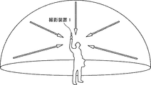
図1に示されているように、本実施形態の画像共有システムは、撮影装置1、複数の通信端末(3a,3b,3c,3d)、画像処理システム5、及び画像管理システム7によって構築されている。また、各通信端末(3a,3b,3c,3d)は、それぞれユーザ(A,B,C,D)によって利用される。また、本実施形態では、撮影装置1は、ユーザAによって操作される場合を示している。なお、以下では、複数の通信端末(3a,3b,3c,3d)のうち、任意の通信端末を「通信端末3」として表す。
As shown in FIG. 1, the image sharing system of the present embodiment is constructed by a photographing
また、撮影装置1は、全天球パノラマ画像を得るためのデジタルカメラである。通信端末3は、スマートフォン、タブレット端末、ノート型パソコン、デスクトップ型パソコン、又はPDA(Personal Data Assistance)等のコンピュータである。更に、画像処理システム5及び画像管理システム7は、それぞれ単一又は複数のサーバコンピュータである。
The photographing
また、撮影装置1は、通信端末3とNFC(Near Field Communication)規格、BlueTooth(登録商標)、WiFi(Wireless Fidelity)、TransferJet(登録商標)等による短距離無線技術によって通信することができる。更に、通信端末3は、通信ネットワーク9を介して、画像処理システム5及び画像管理システム7と通信することができる。この通信ネットワーク9は、3G(3rd Generation)、又はWiMAX(Worldwide Interoperability for Microwave Access)等の移動通信システムによる無線通信網及び各基地局(9a,9b,9c,9d)、並びにインターネットによって構築される。なお、撮影装置1と通信端末3との間、及び通信端末3と通信ネットワーク9との間は、それぞれ有線による通信を行ってもよい。
In addition, the photographing
次に、図2を用いて、撮影装置1の外観を説明する。なお、図2(a)は撮影装置の左側面図であり、図2(b)は撮影装置の正面図であり、図2(c)は撮影装置の平面図である。
Next, the external appearance of the
図2(a)に示されているように、撮影装置1は、人間が片手で持つことができる大きさである。また、図2(a),(b),(c)に示されているように、撮影装置1の上部には、正面側(前側)に撮像素子103a及び背面側(後側)に撮像素子103bが設けられている。また、図2(b)に示されているように、撮影装置1の正面側には、シャッターボタン等の操作部115が設けられている。
As shown in FIG. 2A, the photographing
次に、図3を用いて、撮影装置1の使用状況を説明する。なお、図3は、撮影装置の使用状況を示したイメージ図である。撮影装置1は、図3に示されているように、ユーザが手に持ってユーザの周りの被写体を撮影するために用いられる。この場合、図2に示されている撮像素子103a及び撮像素子103bによって、それぞれユーザの周りの被写体が撮像されることで、2つの半球画像を得ることができる。
Next, the usage situation of the
次に、図4を用いて、撮影装置1で撮影された画像及び合成された画像を説明する。なお、図4(a)は撮影装置で撮影された半球画像(前側)、図4(b)は撮影装置で撮影された半球画像(後側)、図4(c)はメルカトル図法により表された画像(以下、「メルカトル画像」という)を示した図である。
Next, an image photographed by the photographing
図4(a)に示されているように、撮像素子103aによって得られた画像は、後述の広角レンズ102aによって湾曲した半球画像(前側)となる。また、図4(b)に示されているように、撮像素子103bによって得られた画像は、後述の広角レンズ102bによって湾曲した半球画像(後側)となる。そして、半球画像(前側)と、180度反転された半球画像(後側)とは、撮影装置1によって合成され、図3(c)に示されているように、メルカトル画像が作成される。
As shown in FIG. 4A, an image obtained by the image sensor 103a is a hemispherical image (front side) curved by a wide-angle lens 102a described later. Further, as shown in FIG. 4B, the image obtained by the
次に、図5を用いて、メルカトル画像と、この画像の選択に用いられる選択用画像との関係を説明する。なお、図5(a)はメルカトル画像と選択用画像の部分を示した図、図5(b)は選択用画像を示した図である。このように、図5(a)のメルカトル画像上の破線で示された部分が利用されることで、図5(b)の選択用画像が作成される。この選択用画像は、図1に示されている撮影装置1から通信端末3aに送信され、通信端末3aで表示される。そして、ユーザAが、通信端末3aにおいて図5(b)に示されている選択用画像を選択すると、撮影装置1から通信端末3aへ、図4(c)に示されているメルカトル画像のデータが送信される。この送信されたメルカトル画像は、通信端末3aで保存されると共に、図1に示されている通信ネットワーク9を介して、画像管理システム7に送信される。更にその後、メルカトル画像は、画像管理システム7から通信ネットワーク9を介して、他のユーザの通信端末(3b,3c,3d)に送信され、各通信端末(3b,3c,3d)で保存されることで、メルカトル画像の共有を行うことができる。
Next, the relationship between the Mercator image and the selection image used for selecting this image will be described with reference to FIG. FIG. 5A is a diagram showing portions of a Mercator image and a selection image, and FIG. 5B is a diagram showing a selection image. Thus, the selection image shown in FIG. 5B is created by using the portion indicated by the broken line on the Mercator image shown in FIG. This selection image is transmitted from the photographing
そして、上記各通信端末(3b,3c,3d)では、OpenGL ES(Open Graphics Library for Embedded Systems)が利用されることで、図4(c)に示されているメルカトル画像から、図6に示されている全天球パノラマ画像が作成される。なお、図6は、全天球パノラマ画像を示した図である。また、全天球パノラマ画像は、静止画であっても動画であってもよい。例えば、OpenGL ESによって、仮想の立体球の表面に、図5(a)に示されるメルカトル画像が貼り付けられることで、図6に示されているような3次元の全天球パノラマ画像が作成される。更に、3次元の全天球パノラマではなく、2次元の単なるパノラマ画像であってもよい。なお、仮想の立体球の表面にメルカトル画像を貼り付けることを行っているが、例えば、立方体の表面にメルカトル画像を貼り付けたり、円柱の表面に2次元のパノラマ画像を貼り付けることが行われても良い。 Then, in each of the communication terminals (3b, 3c, 3d), by using OpenGL ES (Open Graphics Library for Embedded Systems), the Mercator image shown in FIG. 4 (c) is shown in FIG. A spherical panoramic image is created. FIG. 6 is a diagram showing an omnidirectional panoramic image. The omnidirectional panoramic image may be a still image or a moving image. For example, the Mercator image shown in Fig. 5 (a) is pasted on the surface of a virtual three-dimensional sphere by OpenGL ES to create a three-dimensional panoramic image as shown in Fig. 6 Is done. Further, it may be a two-dimensional panoramic image instead of a three-dimensional panoramic panorama. The Mercator image is pasted on the surface of the virtual solid sphere. For example, the Mercator image is pasted on the surface of the cube, or the two-dimensional panoramic image is pasted on the surface of the cylinder. May be.
次に、図7及び図8を用いて、全天球パノラマ画像における所定領域Tの画像(以下、「所定領域画像」と示す)の特定及び表示の処理について説明する。なお、図7は、全天球パノラマ画像を3次元の仮想の立体球の表面とした場合の仮想カメラの位置及び所定領域の位置を示した図である。また、図8(a)は図7の立体斜視図、図8(b)及び図8(c)はディスプレイに所定領域画像が表示された通信端末を示す図である。 Next, processing for specifying and displaying an image of the predetermined region T (hereinafter referred to as “predetermined region image”) in the omnidirectional panoramic image will be described with reference to FIGS. 7 and 8. FIG. 7 is a diagram showing the position of the virtual camera and the position of the predetermined area when the omnidirectional panoramic image is the surface of a three-dimensional virtual solid sphere. FIG. 8A is a three-dimensional perspective view of FIG. 7, and FIGS. 8B and 8C are diagrams illustrating a communication terminal in which a predetermined area image is displayed on a display.
図7に示されている仮想カメラICは、全天球パノラマ画像としての立体球CSの内部から、この立体球CSの表面に表されている全天球パノラマ画像を見る仮想のユーザの視点に位置している。図7では、特に、仮想カメラICが立体球の中心に位置し、仮想カメラICは、この中心における3軸の回転(Yaw,Pitch,Roll)を行うことができる。また、全天球パノラマ画像における所定領域Tは、仮想カメラICによって撮影される全天球パノラマ画像上の一部分であり、所定領域情報によって特定される。この所定領域情報は、座標x(rH)、座標y(rV)、及び画角α(angle)によって示される。 The virtual camera IC shown in FIG. 7 is used as a viewpoint of a virtual user who views the panoramic image displayed on the surface of the solid sphere CS from the inside of the solid sphere CS as the panoramic image. positioned. In FIG. 7, in particular, the virtual camera IC is positioned at the center of the solid sphere, and the virtual camera IC can perform three-axis rotation (Yaw, Pitch, Roll) at this center. The predetermined area T in the omnidirectional panoramic image is a part of the omnidirectional panoramic image photographed by the virtual camera IC, and is specified by the predetermined area information. This predetermined area information is indicated by coordinates x (rH), coordinates y (rV), and angle of view α (angle).
ここで、図9を用いて、所定領域情報を更に詳細に説明する。なお、図9は、所定領域情報と所定領域画像との関係を示した図である。図9に示されているように、仮想カメラICの画角αによって表される所定領域Tの対角線画角を2Lとした場合の中心点CPが、所定領域情報の(x,y)パラメータとなる。なお、fは仮想カメラICから中心点CPまでの距離である。そして、図9では、一般的に以下の式(1)で示される三角関数が成り立つ。 Here, the predetermined area information will be described in more detail with reference to FIG. FIG. 9 is a diagram showing the relationship between the predetermined area information and the predetermined area image. As shown in FIG. 9, the center point CP when the diagonal field angle of the predetermined area T represented by the field angle α of the virtual camera IC is 2L is the (x, y) parameter of the predetermined area information. Become. Note that f is the distance from the virtual camera IC to the center point CP. In FIG. 9, a trigonometric function represented by the following formula (1) is generally established.
Lf=tan(α/2)・・・式(1)
なお、所定領域Tのズームは、画角αの範囲(円弧)を広げたり縮めたりすることで表現することができる。
Lf = tan (α / 2) Expression (1)
The zoom of the predetermined area T can be expressed by expanding or contracting the range (arc) of the angle of view α.
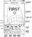
そして、図8(a)で示されている全天球パノラマ画像における所定領域Tの画像は、図8(b)に示されているように、通信端末3dのディスプレイ315に、所定領域画像として表示される。この場合の所定領域画像は、全天球パノラマ画像の一部分を示す部分画像P0である。この部分画像P0は、図6に示された全天球パノラマ画像において、初期設定(デフォルト)された所定領域情報によって表された画像である。
Then, the image of the predetermined area T in the omnidirectional panoramic image shown in FIG. 8A is displayed as a predetermined area image on the
また、所定領域画像(部分画像P0)上には、図8(b)に示されているように、本実施形態の画像共有システムを利用する単一又は複数のユーザによって注目されて設定された複数の注目点(AP1,AP2,AP3,AP4)が表示される。更に、各注目点(AP1,AP2,AP3,AP4)を含んだ一定範囲の所定領域Tの画像は、それぞれディスプレイ315の下部に、サムネイル(T1,T2,T3,T4)の状態で表示される。そして、ユーザが、例えば、サムネイルT1を選択すると、図8(c)に示されているように、サムネイルT1に関連付けられている所定領域情報に基づいて、全天球パノラマ画像における所定領域画像(ここでは、部分画像P1)が、ディスプレイ315に表示されることになる。なお、図8(b)、(c)に示されているサムネイルは、通信端末3によって作成された画像である。
Further, on the predetermined area image (partial image P 0 ), as shown in FIG. 8B, the attention is set by one or a plurality of users using the image sharing system of the present embodiment. A plurality of attention points (AP1, AP2, AP3, AP4) are displayed. Further, images of a predetermined area T within a certain range including each point of interest (AP1, AP2, AP3, AP4) are displayed in the state of thumbnails (T1, T2, T3, T4) at the bottom of the
<<実施形態のハードウェア構成>>
次に、図10乃至図12を用いて、本実施形態の撮影装置、通信端末、画像処理システム、及び画像管理システムのハードウェア構成を詳細に説明する。
<< Hardware Configuration of Embodiment >>
Next, the hardware configuration of the imaging apparatus, communication terminal, image processing system, and image management system according to the present embodiment will be described in detail with reference to FIGS.
まず、図10を用いて、撮影装置1のハードウェア構成を説明する。なお、図10は、撮影装置のハードウェア構成図である。以下では、撮影装置1は、2つの撮像素子を使用した全方位撮影装置とするが、撮像素子は3つ以上いくつでもよく、また、必ずしも全方位撮影専用の装置である必要はない。
First, the hardware configuration of the photographing
図10に示されているように、撮影装置1は、撮像ユニット101、画像処理ユニット104、撮像制御ユニット105、CPU(Central Processing Unit)111、ROM(Read Only Memory)112、SRAM(Static Random Access Memory)113、DRAM(Dynamic Random Access Memory)114、操作部115、ネットワークI/F116、通信部117、及びアンテナ117aによって構成されている。
As shown in FIG. 10, the
このうち、撮像ユニット101は、各々半球画像を結像するための180°以上の画角を有する広角レンズ(いわゆる魚眼レンズ)102a,102bと、各広角レンズに対応させて設けられている2つの撮像素子103a,103bを備えている。撮像素子103a,103bは、広角レンズによる光学像を電気信号の画像データに変換して出力するCMOS(Complementary Metal Oxide Semiconductor)センサやCCD(Charge Coupled Device)センサなどの画像センサ、この画像センサの水平又は垂直同期信号や画素クロックなどを生成するタイミング生成回路、この撮像素子の動作に必要な種々のコマンドやパラメータなどが設定されるレジスタ群などを有している。
Among these, the
撮像ユニット101の撮像素子103a,103bは、各々、画像処理ユニット104とはパラレルI/Fバスで接続されている。一方、撮像ユニット101の撮像素子103a,103bは、撮像制御ユニット105とは別に、シリアルI/Fバス(I2Cバス等)で接続されている。画像処理ユニット104及び撮像制御ユニット105は、バス110を介してCPU111と接続される。さらに、バス100には、ROM112、SRAM113、DRAM114、操作部115、ネットワークI/F116なども接続される。
The
画像処理ユニット104は、撮像素子103a,103bから出力される画像データをパラレルI/Fバスを通して取り込み、それぞれの画像データに対して所定の処理を施した後、これらの画像データを合成処理して、図4(c)に示されているようなメルカトル画像のデータを作成する。
The
撮像制御ユニット105は、一般に撮像制御ユニット105をマスタデバイス、撮像素子103a,103bをスレーブデバイスとして、I2Cバスを利用して、撮像素子103a,103bのレジスタ群にコマンド等を設定する。必要なコマンド等は、CPU111から受け取る。また、該撮像制御ユニット105は、同じくI2Cバスを利用して、撮像素子103a,103bのレジスタ群のステータスデータ等を取り込み、CPU111に送る。
In general, the
また、撮像制御ユニット105は、操作部115のシャッターボタンが押下されたタイミングで、撮像素子103a,103bに画像データの出力を指示する。撮影装置によっては、ディスプレイによるプレビュー表示機能や動画表示に対応する機能を持つ場合もある。この場合は、撮像素子103a,103bからの画像データの出力は、所定のフレームレート(フレーム/分)によって連続して行われる。
The
また、撮像制御ユニット105は、後述するように、CPU111と協働して撮像素子103a,103bの画像データの出力タイミングの同期をとる同期制御手段としても機能する。なお、本実施形態では、撮影装置には表示部が設けられていないが、表示部を設けてもよい。
Further, as will be described later, the
CPU111は、撮影装置1の全体の動作を制御すると共に必要な処理を実行する。ROM112は、CPU111のための種々のプログラムを記憶している。SRAM113及びDRAM114はワークメモリであり、CPU111で実行するプログラムや処理途中のデータ等を記憶する。特にDRAM114は、画像処理ユニット104での処理途中の画像データや処理済みのメルカトル画像のデータを記憶する。
The CPU 111 controls the overall operation of the photographing
操作部115は、種々の操作ボタンや電源スイッチ、シャッターボタン、表示と操作の機能を兼ねたタッチパネルなどの総称である。ユーザは操作ボタンを操作することで、種々の撮影モードや撮影条件などを入力する。
The
ネットワークI/F116は、SDカードやUSBメモリ等の外付けのメディアやパーソナルコンピュータなどとのインターフェース回路(USB I/F等)の総称である。また、ネットワークI/F116としては、無線、有線を問わずにネットワークインタフェースである場合も考えられる。DRAM114に記憶されたメルカトル画像のデータは、このネットワークI/F116を介して外付けのメディアに記録されたり、必要に応じて、ネットワークI/FとなるネットワークI/F116を介して、通信端末3等の外部装置に送信される。
The network I / F 116 is a generic name for an interface circuit (such as a USB I / F) with an external medium such as an SD card or a USB memory, or a personal computer. Further, the network I / F 116 may be a network interface regardless of wireless or wired. The data of the Mercator image stored in the
通信部117は、アンテナ117aを介して、WiFi(Wireless Fidelity)やBluetooth(登録商標)等の短距離無線技術によって、通信端末3等の外部装置と通信を行う。この通信部117によっても、メルカトル画像のデータを通信端末3の外部装置に送信することができる。
The communication unit 117 communicates with an external device such as the
次に、図11を用いて、通信端末3のハードウェア構成を説明する。なお、図11は、通信端末がスマートフォンの場合のハードウェア構成図である。
Next, the hardware configuration of the
図11に示されているように、通信端末3は、通信端末3全体の動作を制御するCPU301、基本入出力プログラムを記憶したROM302、CPU301のワークエリアとして使用されるRAM(Random Access Memory)303、CPU301の制御にしたがってデータの読み出し又は書き込みを行うEEPROM(Electrically Erasable and Programmable ROM)304、CPU301の制御に従って被写体を撮像し画像データを得る撮像素子としてのCMOS305、地磁気を検知する電子磁気コンパスやジャイロコンパス、加速度センサー等の各種加速度・方位センサー306、フラッシュメモリ等の記録メディア307に対するデータの読み出し又は書き込み(記憶)を制御するメディアドライブ308を備えている。そして、メディアドライブ308の制御に従って、既に記録されていたデータが読み出され、又は新たにデータが書き込まれて記憶する記録メディア307が着脱自在な構成となっている。
As shown in FIG. 11, the
なお、EEPROM104には、CPU301が実行するオペレーティングシステム(OS)、その他のプログラム、及び、種々データが記憶されている。また、CMOS305の代わりにCCDを用いてもよい。
Note that the
更に、通信端末3は、音声を音声信号に変換する音声入力部311、音声信号を音声に変換する音声出力部312、アンテナ313a、このアンテナ313aを利用して無線通信信号により、最寄の基地局9a等と通信を行う通信部313、GPS(Global Positioning Systems)衛星から通信端末3の位置情報(緯度、経度、および高度)を含んだGPS信号を受信するGPS受信部314、被写体の画像や各種アイコン等を表示する液晶や有機ELなどのディスプレイ315、このディスプレイ315上に載せられ、感圧式又は静電式のパネルによって構成され、指やタッチペン等によるタッチによってディスプレイ315上におけるタッチ位置を検出するタッチパネル316、及び、上記各部を電気的に接続するためのアドレスバスやデータバス等のバスライン310を備えている。
Further, the
なお、音声入力部311は、音声を入力するマイクが含まれ、音声出力部312には、音声を出力するスピーカが含まれている。
Note that the
次に、図12を用いて、画像処理システム5、及び画像管理システム7のハードウェア構成を説明する。なお、図12は、画像処理システム5、及び画像管理システム7のハードウェア構成図である。画像処理システム5、及び画像管理システム7は、ともに一般のサーバコンピュータであるため、以下では、画像処理システム5の構成について説明し、画像管理システム7の構成の説明は省略する。
Next, the hardware configuration of the
画像処理システム5は、画像処理システム5全体の動作を制御するCPU501、IPL等のCPU501の駆動に用いられるプログラムを記憶したROM502、CPU501のワークエリアとして使用されるRAM503、画像処理システム5用のプログラム等の各種データを記憶するHD504、CPU501の制御にしたがってHD504に対する各種データの読み出し又は書き込みを制御するHDD(Hard Disk Drive)505、フラッシュメモリ等の記録メディア506に対するデータの読み出し又は書き込み(記憶)を制御するメディアドライブ507、カーソル、メニュー、ウィンドウ、文字、又は画像などの各種情報を表示するディスプレイ508、通信ネットワーク9を利用してデータ通信するためのネットワークI/F509、文字、数値、各種指示などの入力のための複数のキーを備えたキーボード511、各種指示の選択や実行、処理対象の選択、カーソルの移動などを行うマウス512、着脱可能な記録媒体の一例としてのCD−ROM(Compact Disc Read Only Memory)513に対する各種データの読み出し又は書き込みを制御するCD−ROMドライブ514、及び、上記各構成要素を図12に示されているように電気的に接続するためのアドレスバスやデータバス等のバスライン510を備えている。
The
<<実施形態の機能構成>>
次に、図13を用いて、本実施形態の機能構成について説明する。図13は、本実施形態の画像共有システムの一部を構成する通信端末3、画像処理システム5、及び画像管理システム7の各機能ブロック図である。図13では、通信端末3、画像処理システム5、及び画像管理システム7が、通信ネットワーク9を介してデータ通信することができる。
<< Functional Configuration of Embodiment >>
Next, the functional configuration of this embodiment will be described with reference to FIG. FIG. 13 is a functional block diagram of the
<通信端末の機能構成>
図13に示されているように、通信端末3は、送受信部31、操作入力受付部32、作成部33、表示制御部34、及び記憶・抽出部39を有している。これら各部は、図11に示されている各構成要素のいずれかが、ROM302又はEEPROM304からRAM303上に展開された通信端末3用のプログラムに従ったCPU301からの命令によって動作することで実現される機能又は手段である。
<Functional configuration of communication terminal>
As illustrated in FIG. 13, the
また、通信端末3は、図11に示されているROM302、RAM303、及びEEPROM304によって構築される記憶部3000を有している。この記憶部3000には、後述の所定領域管理テーブルによって構成されている所定領域管理DB(Data Base)3001が構築される。また、記憶部3000には、撮影画像(メルカトル画像)、選択用画像、及びサムネイルの各データが記憶される。
Further, the
(所定領域管理テーブル)
図14は、所定領域管理テーブルを示す概念図である。この所定領域管理テーブルでは、所定領域管理情報が管理されている。この所定領域管理情報では、サムネイルを識別するためのサムネイル識別情報、全天球パノラマ画像を識別するための画像識別情報、この全天球パノラマ画像における所定領域を特定するための所定領域情報、及びこの所定領域に関連する複数の関連情報が対応付けられている。
(Predetermined area management table)
FIG. 14 is a conceptual diagram showing a predetermined area management table. In this predetermined area management table, predetermined area management information is managed. In the predetermined area management information, thumbnail identification information for identifying a thumbnail, image identification information for identifying the omnidirectional panoramic image, predetermined area information for identifying a predetermined area in the omnidirectional panoramic image, and A plurality of pieces of related information related to the predetermined area are associated with each other.
このうち、サムネイル識別情報は、例えば、サムネイルを識別するためのサムネイルIDである。なお、サムネイルを一意に特定することができれば、サムネイルIDではなく、サムネイルのファイル名等であってもよい。 Among these, the thumbnail identification information is, for example, a thumbnail ID for identifying a thumbnail. As long as the thumbnail can be uniquely identified, the thumbnail file name may be used instead of the thumbnail ID.
また、画像識別情報は、例えば、全天球パノラマ画像を識別するための画像IDである。なお、画像を一意に特定することができれば、画像IDではなく、ファイル名等であってもよい。 The image identification information is, for example, an image ID for identifying an omnidirectional panoramic image. As long as an image can be uniquely identified, a file name or the like may be used instead of an image ID.
更に、関連情報には、例えば、全天球パノラマ画像における所定領域画像がユーザによって特定された年月日を示す「特定年月日(Date)」、この所定領域画像を特定したユーザを示す「特定者名(User)」、及びこの所定領域画像のシーンを示した「シーン(Scene)」が含まれている。なお、関連情報の別の例として、全天球パノラマ画像における所定領域画像が特定された年月日に加え、特定時間、又は、撮影画像の撮影場所等が含まれていてもよい。 Furthermore, the related information includes, for example, “specific date (Date)” indicating the date on which the predetermined area image in the omnidirectional panoramic image is specified by the user, and “the user who specified the predetermined area image”. “Specific user name (User)” and “Scene” indicating the scene of the predetermined area image are included. As another example of the related information, in addition to the date on which the predetermined region image in the omnidirectional panoramic image is specified, a specific time or a shooting location of the shot image may be included.
(通信端末の各機能構成)
次に、図11及び図13を用いて、通信端末3の各機能構成について更に詳細に説明する。
(Functional configuration of communication terminal)
Next, each functional configuration of the
通信端末3の送受信部31は、主に、図11に示されている通信部313及びCPU301の処理によって実現され、通信ネットワーク9を介して画像処理システム5、又は画像管理システム7と各種データ(または情報)の送受信を行う。
The transmission /
操作入力受付部32は、主にタッチパネル316及びCPU301による処理によって実現され、ユーザから各種の選択又は入力を受け付ける。
The operation
作成部33は、主にCPU301の処理によって実現され、記憶・抽出部39によって抽出された画像識別情報で識別される全天球パノラマ画像における所定領域画像(記憶・抽出部39によって抽出された所定領域情報で特定されている所定領域画像)に基づいて、この所定領域画像に関するサムネイルを作成すると共に、この作成したサムネイルを識別するためのサムネイル識別情報を作成する。また、作成部33は、サムネイルとサムネイル識別情報とを関連付ける。
The
更に、作成部33は、所定領域管理DB3001で管理されている所定領域管理情報の各関連情報に基づいて、後述の関連情報選択メニューを作成する。例えば、作成部33が特定者名を示す関連情報選択メニューを作成する場合には、関連情報から各特定者名を注抽出して、後述の図29(a)に示されているような各特定者名を示す関連情報選択メニューを作成する。
Furthermore, the
表示制御部34は、主にCPU301の処理によって実現され、ディスプレイ315に各種画像や文字等を表示させるための制御を行う。表示制御部34は、例えば、操作入力受付部32によって選択を受け付けられた所定の関連情報に対応する画像識別情報で識別される全天球パノラマ画像において、この選択を受け付けられた所定の関連情報に対応する所定領域情報で特定されている所定領域画像に関するサムネイルを、ディスプレイ315に表示させる。
The
また、表示制御部34は、操作入力受付部32によって選択されたサムネイルに関する所定領域画像を、ディスプレイ315に表示させる。
Further, the
更に、表示制御部34は、ディスプレイ315に表示されている所定領域画像上に、後述の図27に示されているように、所定領域画像が特定された年月日を選択するための関連情報選択メニュー(特定年月日選択メニュー)3141を表示させる。この場合、記憶・抽出部39が、予め記憶部3000に記憶されていた特定年月日選択メニューのデータを読み出すことで、表示制御部34が、特定年月日選択メニューを表示させることができる。
Furthermore, the
記憶・抽出部39は、記憶部3000に各種データ(または情報)を記憶したり、記憶部3000から各種データ(または情報)を抽出する。記憶・抽出部39は、例えば、撮影画像(メルカトル画像)、選択用画像、又はサムネイルの各データを、記憶部3000に対して記録したり、記憶部3000から抽出する。また、記憶・抽出部39は、例えば、操作入力受付部32によって受け付けられた所定の関連情報に基づいて、所定領域管理DB3001を検索することにより、対応する画像識別情報及び所定領域情報を抽出する。なお、この場合、表示制御部34は、記憶・抽出部39によって抽出された画像識別情報で識別される全天球パノラマ画像において、記憶・抽出部39によって抽出された所定領域情報で特定されている所定領域画像に関するサムネイルを、ディスプレイ315に表示させることになる。
The storage /
<画像処理システムの機能構成>
次に、図13を用いて、画像処理システム5の各機能構成について詳細に説明する。画像処理システム5は、送受信部51、シーン設定部52、及び記憶・抽出部59を有している。これら各部は、図12に示されている各構成要素のいずれかが、HD504からRAM503上に展開された画像処理システム5用のプログラムに従ったCPU501からの命令によって動作することで実現される機能又は手段である。
<Functional configuration of image processing system>
Next, each functional configuration of the
また、画像処理システム5は、図12に示されているRAM503、及びHD504によって構築される記憶部5000を有している。この記憶部5000には、各種データ(または情報)が記憶される。
Further, the
(画像処理システムの各機能構成)
次に、図12及び図13を用いて、画像処理システム5の各機能構成について詳細に説明する。
(Functional configuration of image processing system)
Next, each functional configuration of the
画像処理システム5の送受信部51は、主に、図12に示されているネットワークI/F509及びCPU501の処理によって実現され、通信ネットワーク9を介して通信端末3、又は画像管理システム7と各種データ(または情報)の送受信を行う。
The transmission /
シーン設定部52は、全天球パノラマ画像における所定領域画像の色や明るさ等の情報に基づいて、所定領域画像が、人影(Figure)、風景(Landscape)、建物(Structure)、及び、その他(Other)のいずれのシーンを示している画像であるかを判断、所定領域画像に最適なシーンを設定する。このシーンの設定方法は、全天球パノラマ画像における色情報や形状情報に基づき、デジタルカメラにおける一般的な自動風景認識機能を用いて行われる。
Based on information such as the color and brightness of the predetermined area image in the omnidirectional panoramic image, the
記憶・抽出部59は、記憶部5000に各種データ(または情報)を記憶したり、記憶部5000から各種データ(または情報)を抽出する。
The storage /
<画像管理システムの機能構成>
次に、図12及び図13を用いて、画像管理システム7の機能構成について詳細に説明する。画像管理システム7は、送受信部71、管理部72、及び、記憶・抽出部79を有している。これら各部は、これら各部は、図12に示されている各構成要素のいずれかが、HD504からRAM503上に展開された画像管理システム7用のプログラムに従ったCPU501からの命令によって動作することで実現される機能又は手段である。
<Functional configuration of image management system>
Next, the functional configuration of the
また、画像管理システム7は、図12に示されているRAM503、及びHD504によって構築される記憶部7000を有している。この記憶部7000には、後述の画像管理テーブルによって構成されている画像管理DB7001が構築される。更に、記憶部7000には、後述の所定領域管理テーブルによって構成されている所定領域管理DB7002も構築されている。
Further, the
(画像管理テーブル)
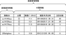
図15は、画像管理テーブルを示す概念図である。この画像管理テーブルでは、画像管理情報が管理されている。この画像管理情報では、全天球パノラマ画像(撮影画像)を識別するための画像識別情報、及びこの全天球パノラマ画像のメタデータ等である付属情報が対応付けられている。
(Image management table)
FIG. 15 is a conceptual diagram showing an image management table. In this image management table, image management information is managed. In this image management information, image identification information for identifying an omnidirectional panoramic image (captured image) and associated information such as metadata of the omnidirectional panoramic image are associated with each other.
このうち、画像識別情報は、図14に示されている画像識別情報と同じ情報である。また、付属情報には、ユーザが撮影画像を、本実施形態の画像共有システムで公開するか否かを示した「公開情報」、「撮影画像のデータサイズ(MB)」、「撮影画像の撮影年月日時」、及び「注目点数」が含まれている。ここで、公開情報が「○」の場合は公開することを示し、公開情報が「×」の場合は公開しないことを示す。また、注目点数は、図8(b)に示されているように、1つの全天球パノラマ画像において設定された注目点の数である。なお、付属情報の別の例として、撮影画像が撮影された年月日時に加え、撮影画像の撮影場所等が含まれていてもよい。 Among these, the image identification information is the same information as the image identification information shown in FIG. The attached information includes “public information”, “data size (MB) of captured image”, “captured image of captured image” indicating whether the user releases the captured image with the image sharing system of the present embodiment. “Date / Time” and “Number of Points of Interest” are included. Here, when the public information is “◯”, it indicates that the information is disclosed, and when the public information is “×”, it indicates that the information is not disclosed. The number of attention points is the number of attention points set in one omnidirectional panoramic image, as shown in FIG. As another example of the attached information, in addition to the year / month / date / time when the photographed image was photographed, the photographing location of the photographed image may be included.
(所定領域管理テーブル)
図16は、所定領域管理テーブルを示す概念図である。なお、図16に示されている所定領域管理テーブルは、各ユーザによってアップロードされた撮影画像を管理するために用いられるのに対して、図14に示されている所定領域管理テーブルは、ユーザ個人によって通信端末3のローカルで撮影画像を管理するために用いられる。
(Predetermined area management table)
FIG. 16 is a conceptual diagram showing a predetermined area management table. Note that the predetermined area management table shown in FIG. 16 is used to manage captured images uploaded by each user, whereas the predetermined area management table shown in FIG. Is used to manage captured images locally in the
(画像管理システムの各機能構成)
次に、図13を用いて、画像管理システム7の各機能構成について詳細に説明する。
(Each functional configuration of the image management system)
Next, each functional configuration of the
画像管理システム7の送受信部71は、主に、図12に示されているネットワークI/F509及びCPU501の処理によって実現され、通信ネットワーク9を介して通信端末3、又は画像処理システム5と各種データ(または情報)の送受信を行う。
The transmission /
管理部72は、通信端末3から送られて来た撮影画像を画像管理システム7で管理するために、この撮影画像のデータのヘッダ部分に画像識別情報を付与する。
The
記憶・抽出部79は、記憶部7000に各種データ(または情報)を記憶したり、記憶部5000から各種データ(または情報)を抽出する。
The storage /
<<実施形態の処理または動作>>
続いて、図17乃至図25を用いて、本実施形態の処理または動作について説明する。まずは、図17を用いて、撮影画像のアップロードの処理を説明する。なお、図17は、撮影画像のアップロードの処理を示したシーケンス図である。
<< Processing or Operation of Embodiment >>
Next, the processing or operation of the present embodiment will be described with reference to FIGS. First, the process of uploading a captured image will be described with reference to FIG. FIG. 17 is a sequence diagram illustrating processing for uploading a captured image.
図17に示されているように、撮影装置1は、図4(a)、(b)で示されている2つの半球画像を合成することによって、図(4)(c)で示されている撮影画像(メルカトル画像)を作成し、更に、図5に示されているように、撮影画像から選択用画像を作成する(ステップS1)。
As shown in FIG. 17, the photographing
次に、通信端末3aは、撮影装置1に対して、選択用画像を要求する(ステップS2)。これにより、撮影装置1は、通信端末3aに対して、上記ステップS1で作成された選択用画像と、この選択用画像の元になる撮影画像の画像IDとを送信する(ステップS3)。これにより、通信端末3aの送受信部31は、選択用画像及び画像IDを受信することになる。
Next, the
次に、通信端末3aの表示制御部34は、図11に示されているディスプレイ315に、選択用画像を表示させて、ユーザAに対して選択用画像の選択を促す(ステップS4)。これにより、ユーザAが、ディスプレイ315のタッチパネル316上の選択用画像の部分を選択すると、操作入力受付部32が選択を受け付ける(ステップS5)。これに伴い、送受信部31が撮影装置1に対して、選択用画像の元になる撮影画像を要求する(ステップS6)。この場合、送受信部31は、上記ステップS3によって送られて来た画像IDを、撮影装置1側に送り返すことで、所望の撮影画像を特定する。これにより、撮影装置1は、撮影画像の要求を受け付けることになる。
Next, the
次に、撮影装置1は、通信端末3aに対して、上記ステップS5によって要求を受け付けた撮影画像と、この撮影画像のメタデータ等の付属情報を送信する(ステップS7)。これにより、通信端末3aの送受信部31は、撮影画像及び付属情報を受信することになる。
Next, the
次に、通信端末3aの表示制御部34は、ディスプレイ315上に撮影画像を表示させる(ステップS8)。これにより、ユーザAは、画像管理システム7へアップロードする撮影画像を確認することができる。
Next, the
そして、ユーザAが撮影画像をアップロードする場合には、通信端末3aの送受信部31が、画像管理システム7に対して、撮影画像を送信する(ステップS9)。また、この際、送信される撮影画像の付属情報も送信される。これにより、画像管理システム7の送受信部71は、撮影画像及び付属情報を受信することになる。
When the user A uploads a captured image, the transmission /
次に、画像管理システム7の管理部72は、ステップS7によって受信された撮影画像を画像管理システム7で管理するために、この撮影画像のデータのヘッダ部分に画像識別情報を付与する(ステップS10)。なお、画像識別情報は、上記ステップS3,5で送受信された画像IDとは別のIDであり、画像管理システム7で独自に撮影画像を管理するために付与されるIDである。
Next, the
そして、記憶・抽出部79は、撮影画像に付与された画像識別情報と同じ画像識別情報と、上記ステップS8によって受信された付属情報とを対応付けることで、画像管理情報として画像管理DB7001に記憶する(ステップS11)。
The storage /
次に、管理部72は、撮影画像から共有選択用画像を作成し、この共有選択用画像のデータのヘッダ部分に、上記ステップS10で付与された画像識別情報と同じ画像識別情報を付与する(ステップS12)。なお、この共有選択用画像は、各ユーザが、画像管理システム7から所望の撮影画像をダウンロードする前に選択されることで、ダウンロードされる撮影画像を特定するための画像である。また、共有選択画像は、図19に示されており、後ほど更に説明する。また、共有選択用画像は、例えば、上記ステップS1及び図5で示された方法と同じ方法によって作成される。
Next, the
次に、記憶・抽出部79は、上記ステップS10によって画像識別情報が付与された撮影画像と、上記ステップS11によって画像識別情報が付与された共有選択用画像とを、記憶部7000に記憶する(ステップS13)。即ち、画像管理DB7001で管理されている画像管理情報、並びに、記憶部7000で管理されている撮影画像及び共有選択用画像は、同じ画像識別情報によって関連付けられることになる。
Next, the storage /
続いて、図18を用いて、通信端末3bが、撮影画像及び所定領域管理情報をダウンロードする処理を説明する。なお、図18は、撮影画像及び所定領域管理情報のダウンロードの処理を示したシーケンス図である。
Next, a process in which the
まず、通信端末3bの送受信部31は、画像管理システム7に対して、共有選択用画像、及び画像管理情報を要求する(ステップS21)。これにより、画像管理システム7の送受信部71は、要求を受け付けることになる。
First, the transmission /
次に、画像管理システム7の記憶・抽出部79は、記憶部7000から共有選択用画像のデータを読み出すとともに、記憶部7000の画像管理DB7001から画像管理情報を読み出す(ステップS22)。そして、送受信部71は、要求元である通信端末3bへ、上記ステップS22によって読み出された共有選択用画像及び画像管理情報を送信する(ステップS23)。これにより、通信端末3bの送受信部31は、共有選択用画像及び画像管理情報を受信することになる。そして、通信端末3bの記憶・抽出部39は、記憶部1000に、上記ステップS23によって受信された共有選択用画像及び画像管理情報を記憶する(ステップS24)。
Next, the storage /
次に、通信端末3bの作成部33は、共有選択用画像及び画像管理情報に基づいて、撮影画像を選択するための共有画像選択リストを作成する(ステップS25)。そして、通信端末3bの表示制御部34は、図19(a)に示されているように、通信端末3bのディスプレイ315に共有画像選択リストSLを表示させることで、ユーザBに対して、共有選択用画像CEの選択を促す(ステップS26)。なお、共有画像選択リストSLは、図19(a)に示されているように、画像管理情報が付加された共有選択用画像CEを表している。例えば、共有選択用画像CEとして商業地域のビルが表示され、画像管理情報として、撮影日時(2011年9月20日 11時21分)、撮影画像の画像データサイズ(13.1MB)、及び、注目点が設定された数(0個)が表示される。
Next, the
次に、ユーザBが所望の共有選択用画像CEを選択すると、通信端末3bの操作入力受付部32が、選択を受け付ける(ステップS27)。そして、通信端末3bの送受信部31は、画像管理システム7に対して、上記ステップS27によって選択された共有選択用画像CEに付与されている画像識別情報を送信する(ステップS28)。これにより、画像管理システム7の送受信部71は、画像識別情報を受信することになる。
Next, when the user B selects a desired share selection image CE, the operation
次に、画像管理システム7の記憶・抽出部79は、記憶部7000から、上記受信された画像識別情報と同じ画像識別情報が付与されている撮影画像を読み出す(ステップS29)。更に、記憶・抽出部79は、記憶部7000の所定領域管理DB7002から、上記受信された画像識別情報と同じ画像識別情報を含む所定領域管理情報を読み出す(ステップS30)。なお、画像管理システム7では、上記ステップS29の処理の前に、管理部が、画像管理DB7001で管理されている画像管理情報の付属情報における「公開」属性に基づき、非公開の場合(「×」の場合)には、上記ステップS29、S30の処理を行わなくてもよい。
Next, the storage /
次に、送受信部71は、通信端末3bに対して、上記ステップS29によって読み出された撮影画像と、上記ステップS30によって読み出された所定領域管理情報とを送信する(ステップS31)。これにより、通信端末3bの送受信部31が撮影画像及び所定領域管理情報を受信することで、撮影画像のダウンロードが終了する。なお、通信端末3bが受信した撮影画像には、まだ注目点が全く設定されていないため、所定領域管理情報の内容は何もない状態(空の状態)である。
Next, the transmitting / receiving
次に、通信端末3bの記憶・抽出部39は、記憶部1000に上記ステップS31によってダウンロードされた撮影画像を記憶させると共に、記憶部1000の所定領域管理DB3001に上記ステップS31によってダウンロードされた所定領域管理情報を記憶させる(ステップS32)。
Next, the storage /
次に、通信端末3bの作成部33は、撮影画像に基づいて、図6に示されているような全天球パノラマ画像を作成し、表示制御部34は、通信端末3bのディスプレイ315に全天球パノラマ画像を表示させる(ステップS33)。
Next, the
ここで、ユーザBが、タッチパネル316を利用して、ディスプレイ315に表示されている全天球パノラマ画像を拡大するように操作すると、操作入力受付部32がユーザBの操作を受け付けることにより、表示制御部34が、全天球パノラマ画像の一部を図19(b)に示されているような平面の所定領域画像として拡大表示させる。
Here, when the user B operates to enlarge the omnidirectional panoramic image displayed on the
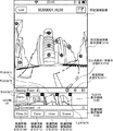
図19(b)では、大別して、ディスプレイ315上に、所定領域画像表示領域3110、サムネイル表示領域3120、及び、関連情報選択領域3130が表示されている。このうち、所定領域画像表示領域3110は、全天球パノラマ画像や図19(b)に示されているような平面の所定領域画像を表示する領域である。また、サムネイル表示領域3120は、ユーザによって設定された注目点を含む所定領域画像に関するサムネイルを表示する領域である。更に、関連情報選択領域3130は、サムネイルの種類を絞り込む際に、ユーザによって選択される領域であり、後述の関連情報選択ボタンが表示される領域である。なお、関連情報選択領域3130には、関連情報選択ボタンを表示するための関連情報種類表示ボタン3130Fが表示されている。ユーザが、この関連情報種類表示ボタン3130Fを選択すると、後述の各種の関連情報選択ボタンが表示されることになる。
In FIG. 19B, a predetermined area image display area 3110, a
続いて、図20を用いて、ユーザBが注目点を含む所定領域を設定して、画像管理システム7に所定領域を登録する場合について説明する。なお、図20は、ユーザによって所定領域が設定されて登録される処理を示したシーケンス図である。
Next, a case where the user B sets a predetermined area including a point of interest and registers the predetermined area in the
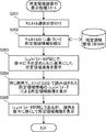
通信端末3bでは、注目点を含む所定領域の設定処理を行う(ステップS41)。ここで、図21及び図22を用いて、ステップS41を更に詳細に説明する。なお、図21は、所定領域の設定処理を示したフローチャートである。また、図22は、所定領域の設定処理を示した画面例である。
The
まず、図22に示されているように、ユーザBが、所定領域画像(部分画像P)のうち、自ら注目した位置である注目点AP1を長押しすると、操作入力受付部32が注目点AP1の受け付けを行う(ステップS41−1)。
First, as shown in FIG. 22, when the user B presses and holds a point of interest AP1 that is a position of interest in the predetermined region image (partial image P) for a long time, the operation
次に、表示制御部34は、図22に示されているように、長押しされた注目点AP1を中心に選択枠3113を表示させる(ステップS41−2)。なお、選択枠3113が目立つように、選択枠3113の周りはマスキングされている。
Next, as shown in FIG. 22, the
次に、ユーザBが、選択枠3113の調整を行うと、操作入力受付部32は、選択枠の調整を受け付ける(ステップS41−3)。この選択枠3113の調整により、図7に示されている仮想カメラの座標と画角が変更されることになる。
Next, when the user B adjusts the
次に、ユーザBが、所定領域決定ボタン3111を押下すると、操作入力受付部32は、上記ステップS41−3によって調整された後の領域で、注目領域の設定を受け付ける(ステップS41−4)。これにより、記憶・抽出部39は、上記ステップS41−4によって受け付けた注目領域に関する所定領域管理情報を、所定領域管理DB3001に記憶する(ステップS41−5)。この通信装置は、この所定領域管理情報を用いて、対象となる撮影画像の所定領域を特定し、サムネイルを生成する。さらに、この通信装置は、この生成されたサムネイルに対応させてサムネイル識別情報を生成し、サムネイルとサムネイル識別情報とを、先の所定領域管理情報と対応づけて、所定領域管理DB3001に記憶される。
Next, when the user B presses the predetermined area determination button 3111, the operation
但し、この時点では、図14に示されているような所定領域管理情報のうち、画像識別情報、所定領域情報、及びシーンを除く関連情報が記憶される。即ち、画像識別情報は、通信端末3で管理されている撮影画像の画像IDである。また、所定領域情報は、上記ステップS41−4で設定された仮想カメラの座標と画角である。更に、関連情報は、上記ステップS41−4で注目点を含む所定領域が設定されることで、所定領域画像が特定された日時、及び、上記ステップS41−4で設定した(所定領域を特定した)ユーザBの名称であり、注目領域のシーンは含まれていない。なお、注目点表示/非表示切替ボタン3112は、後述の注目点を表示又は非表示を切り替えるためのボタンである。
However, at this time, among the predetermined area management information as shown in FIG. 14, the image identification information, the predetermined area information, and the related information excluding the scene are stored. That is, the image identification information is an image ID of a captured image managed by the
次に、図20に戻り、通信端末3bの送受信部31は、画像処理システム5に対して、上記ステップS41−5で記憶された所定領域管理情報と、サムネイル識別情報とを送信する(ステップS42)。これにより、画像処理システム5の送受信部51は、所定領域管理情報と、サムネイル識別情報とを受信することになる。
Next, returning to FIG. 20, the transmission /
次に、画像処理システム5は、画像管理システム7に対して、上記ステップS42によって受信された所定領域管理情報内の画像識別情報を送信することで、この画像識別情報に対応する撮影画像を要求する(ステップS43)。これにより、画像管理システム7の送受信部71は、画像識別情報を受信すると共に、この画像識別情報に対応する撮影画像の要求を受け付けることになる。
Next, the
次に、画像管理システム7では、記憶・抽出部79が、上記ステップS43によって受信された画像識別情報が付与されている撮影画像を、記憶部7000から読み出す(ステップS44)。そして、送受信部71は、画像処理システム5に対して、ステップS44によって読み出された撮影画像を送信する(ステップS45)。これにより、画像処理システム5の送受信部51は、撮影画像を受信することになる。
Next, in the
次に、画像処理システム5では、シーン設定部52が、上記ステップS42によって受信された所定領域管理情報の所定領域情報、及び上記ステップS45によって受信された撮影画像に基づいて、上記ステップS41−4で設定された所定領域のシーンを設定する(ステップS46)。具体的には、シーン設定部52は、撮影画像及び所定領域情報に基づいて、撮影画像における所定領域画像の色や明るさ等の情報に基づいて、人影(Figure)、風景(Landscape)、建物(Structure)、及び、その他(Other)のいずれのシーンであるかを判断し、所定領域画像に最適なシーンを設定する。なお、通信端末3b,3cが、画像管理システム7から、設定済みのシーンの情報を受信するのは、通信端末3b,3cが次に画像管理システム7にアクセスし、図18のステップS21〜S31の処理によって、所定領域管理情報を受信するときである。
Next, in the
次に、画像処理システム5の送受信部51は、画像管理システム7に対して、上記ステップS47によって決定されたシーンを含めた所定領域管理情報と、サムネイル識別情報とを送信する(ステップS47)。これにより、画像管理システム7の送受信部71は、所定領域管理情報と、サムネイル識別情報とを受信することになる。
Next, the transmission /
次に、画像管理システム7の記憶・抽出部79は、上記ステップS47によって受信された所定領域管理情報と、サムネイル識別情報とを、所定領域管理DB7002に記憶することで、新たな所定領域管理情報と、サムネイル識別情報とを追加する(ステップS48)。
Next, the storage /
続いて、図1に示されているユーザBが注目領域を設定した後、ユーザCが、図18に示されているように、画像管理システム7から撮影画像と、所定領域管理情報と、サムネイル識別情報とのダウンロードをする場合について、図23を用いて説明する。なお、図23は、所定領域の設定処理を示した画面例である。このうち、ユーザCの画面である図23(a)は、ユーザBの画面である図19(b)に対応している。また、ユーザCの画面である図23(b)は、ユーザBの画面である図22に対応している。
Subsequently, after the user B shown in FIG. 1 sets the attention area, the user C, as shown in FIG. 18, takes a photographed image, predetermined area management information, thumbnails from the
図23(a)では、所定領域画像(部分画像P)上の特定位置に、ユーザBによって設定された注目点AP1が表示されている。また、サムネイル表示領域3120には、ユーザBによって設定された注目点AP1を含む所定領域画像に関するサムネイルT1が表示されている。更に、サムネイルT1内の右上隅には、本実施形態の画像共有システムを利用する各ユーザが、この所定領域画像を閲覧して入力したコメントの数が表示されている。
In FIG. 23A, the attention point AP1 set by the user B is displayed at a specific position on the predetermined area image (partial image P). In the
なお、サムネイルは、ユーザCの通信端末3cの作成部33によって作成された画像である。この作成部33は、ユーザCが上記ステップS31によってダウンロードされた撮影画像及び所定領域管理情報に基づいてサムネイルを作成する。具体的には、作成部33は、図7に示されているように、ダウンロードされた撮影画像に基づく全天球パノラマ画像において、この撮影画像と共に受信された所定領域管理情報における所定領域情報に基づき仮想カメラICの座標と画角を決定し、この場合の所定領域Tにおける所定領域画像のサイズを縮小することで、サムネイルを作成する。この作成されたサムネイルは、先に受信しているサムネイル識別情報と対応づけられる。
The thumbnail is an image created by the
そして、ユーザCが新たに注目点を追加したい場合、ユーザCは、図23(b)で示されている注目点AP2を指定し、この注目点AP2の周辺を所定領域として設定することで、図20及び図21に示されている処理と同様の処理が行われる。 Then, when the user C wants to add a new point of interest, the user C designates the point of interest AP2 shown in FIG. 23B and sets the periphery of the point of interest AP2 as a predetermined area. Processing similar to that shown in FIGS. 20 and 21 is performed.
以上のようにして、画像共有システムを利用する様々なユーザにより、注目領域の設定が行われることになるため、各ユーザは、他のユーザが注目している箇所を把握することができるため、各ユーザも他のユーザが注目している箇所を迅速に閲覧することができるという効果を奏する。 As described above, because various users who use the image sharing system set the attention area, each user can grasp the location that other users are paying attention to. Each user also has an effect of being able to quickly browse a location that other users are paying attention to.
但し、多数の注目点(所定領域)が設定されてしまうと、所定領域画像を閲覧しようとするユーザを混乱させる恐れがある。そこで、以下では、図1に示されているユーザDが、通信端末3dを用いて、多数のサムネイルのうち、所望のサムネイルに絞り込む処理について、図24乃至図34を用いて説明する。なお、図24は、多数の注目点が表示された図である。図25は、サムネイルの絞込み処理を示したフローチャートである。
However, if a large number of attention points (predetermined areas) are set, there is a risk that a user who wants to view the predetermined area image will be confused. Therefore, hereinafter, a process in which the user D shown in FIG. 1 narrows down to a desired thumbnail among a large number of thumbnails using the
まず、ユーザDは、ユーザB及びユーザCと同様に、ステップS31によってダウンロードされた撮影画像及び所定領域管理情報に基づいて、通信端末3dのディスプレイ315上に、図24に示されているような所定領域画像を表示させる。この所定領域画像上には、多数の注目点(AP1,AP2,AP3,AP4,・・・)が表示されている。また、この状態では、サムネイル表示領域3120にサムネイルは表示されていない。
First, as with the users B and C, the user D, as shown in FIG. 24, is displayed on the
ここで、ユーザDが、多数の注目点(所定領域画像)から、所望の種類の所定領域画像を絞り込むために、図24において、関連情報種類表示ボタン(Filterボタン)3130Fを押下すると、図25に示されているように、操作入力受付部32が押下を受け付ける(ステップS101)。これにより、表示制御部34は、図26に示されているように、関連情報選択領域3130上に、関連情報種類選択ボタン(ここでは、Dateボタン)3131、関連情報種類選択ボタン(ここでは、Userボタン)3132、及び関連情報種類選択ボタン(ここでは、Sceneボタン)3133を表示させる(ステップS102)。なお、図26は、関連情報種類選択ボタンを示した図である。
Here, when the user D presses the related information type display button (Filter button) 3130F in FIG. 24 in order to narrow down a predetermined type of predetermined region image from a number of attention points (predetermined region images), FIG. As shown in FIG. 4, the operation
次に、ユーザDが、上記3つのボタン(3131、3132、3133)のうちのいずれか1つを押下すると、操作入力受付部32は、3つのボタン(3131、3132、3133)のうちのいずれか1つの選択を受け付ける(ステップS103)。更に、操作入力受付部32は、関連情報種類選択ボタン(Dateボタン)3131が受け付けられたか否かを判断する(ステップS104)。
Next, when the user D presses any one of the three buttons (3131, 3132, 3133), the operation
このステップS104によって、関連情報種類選択ボタン(Dateボタン)3131が押下されたと判断された場合には(YES)、記憶・抽出部39が、予め記憶部3000に記憶されている特定年月日選択メニューのデータを読み出す(ステップS105)。そして、表示制御部34が、図27に示されているように、所定領域画像上に関連情報選択メニュー(ここでは、特定年月日選択メニュー)3141を表示させる(ステップS106)。なお、図27は、所定領域画像の特定年月日を示した特定年月日選択メニューを示した図であり、関連情報選択メニューの一例である。
If it is determined in step S104 that the related information type selection button (Date button) 3131 has been pressed (YES), the storage /
次に、ユーザDが、所望の年月日を押下すると、操作入力受付部32は、所定領域画像が特定された日の選択を受け付ける(ステップS107)。そして、記憶・抽出部39は、このステップS106によって受け付けられた年月日の情報を検索キーとして所定領域管理DB3001を検索することにより、受け付けられた年月日と同じ特定年月日の関連情報を含む所定領域管理情報を抽出することで、所定領域管理情報の絞込みを行う(ステップS108)。
Next, when the user D presses down a desired date, the operation
次に、作成部33は、上記ステップS108によって抽出された所定領域管理情報の画像識別情報で示される撮影画像に対して、同じく上記ステップS108によって抽出された所定領域管理情報の所定領域情報を用いて、図7及び図8(a)で示された方法により、所定領域画像を特定すると共に、この所定領域画像からサムネイルを作成する(ステップS109)。なお、作成部33は、上記ステップS106で受け付けた年月日と同じ全ての特定年月日の関連情報を含む所定領域管理情報についても、サムネイルを作成する。また、この際、作成部33は、作成したサムネイルを識別するために、先に受信しているサムネイル識別情報とを関連付けておく。
Next, the
次に、表示制御部34は、作成部33によって作成された全てのサムネイルを、図28に示すように、サムネイル表示領域3120に表示させることで、このサムネイル表示領域3120の表示を更新する(ステップS110)。なお、図28は、サムネイルを示した図である。
Next, the
一方、上記ステップS104において、関連情報種類選択ボタン(Dateボタン)3131が押下されたと判断されなかった場合には(NO)、記憶・抽出部39は、関連情報種類選択ボタン(Userボタン)3132、又は関連情報種類選択ボタン(Sceneボタン)3133のうち、選択されたボタンの名称を示す関連情報を、所定領域管理DB3001から読み出す(ステップS111)。例えば、上記ステップS103によって、関連情報種類選択ボタン(Userボタン)3132が受け付けられた場合には、特定者名(User)の属性(フィールド)内の全ての名称が読み出される。また、上記ステップS103によって、関連情報種類選択ボタン(Sceneボタン)3133が受付された場合には、シーン(Scene)の属性(フィールド)内の全ての名称が読み出される。
On the other hand, if it is not determined in step S104 that the related information type selection button (Date button) 3131 has been pressed (NO), the storage /
次に、作成部33は、上記ステップS111によって読み出された名称に基づいて、関連情報選択メニューを作成する(ステップS112)。例えば、上記ステップS103によって、関連情報種類選択ボタン(Userボタン)3132が選択されていた場合には、作成部33によって、図29(a)に示されているように、所定領域画像を特定した特定者名を示す関連情報選択メニュー(特定者名選択メニュー)3142が作成される。また、上記ステップS103によって、関連情報種類選択ボタン(Sceneボタン)3133が選択されていた場合には、作成部33によって、図29(b)に示されているように、所定領域画像のシーンを示す関連情報選択メニュー(シーン選択メニュー)3143が作成される。
Next, the
なお、図29(a)は所定領域画像の特定者名を示す特定者名選択メニューを示した図であり、関連情報選択メニューの一例である。また、図29(b)は所定領域画像のシーンを示すシーン選択メニューを示した図であり、関連情報選択メニューの一例である。 FIG. 29A is a diagram showing a specific person name selection menu showing a specific person name of a predetermined area image, and is an example of a related information selection menu. FIG. 29B is a diagram showing a scene selection menu showing a scene of a predetermined area image, and is an example of a related information selection menu.
次に、表示制御部34は、上記ステップS112によって作成された関連情報選択メニューを表示させる(ステップS113)。その後は、上記ステップS107項と同様の処理が行われるため、その説明を省略する。
Next, the
続いて、図30及び図34を用いて、所定領域画像の表示処理を説明する。なお、図30は、所定領域画像の表示処理を示すフローチャートである。図34は、サムネイルに対応する所定領域画像を示した図である。 Subsequently, the display process of the predetermined area image will be described with reference to FIGS. 30 and 34. FIG. 30 is a flowchart showing the display processing of the predetermined area image. FIG. 34 is a diagram showing a predetermined area image corresponding to a thumbnail.
まず、ユーザDは、上記ステップS110によって表示されたサムネイルのうち、所望のサムネイルを押下すると、操作入力受付部32は、サムネイルの選択を受け付ける(ステップS201)。そして、記憶・抽出部39は、上記ステップS201によって受け付けられたサムネイルのサムネイル識別情報に基づいて、所定領域管理テーブル(図14参照)を検索することにより、対応する所定領域情報を読み出す(ステップS202)。
First, when the user D presses a desired thumbnail among the thumbnails displayed in step S110, the operation
次に、表示制御部34は、図31に示されているように、図28に示されている所定領域画像に係る所定領域情報の(x,y)パラメータは同じであるが、仮想カメラICの画角を徐々に予め定められている画角にした所定領域画像を表示させる(ステップS203)。なお、図31は、予め定められた画角の所定領域画像を示した図である。ここでは、図28に示されている所定領域画像の場合の画角よりも、図31に示されている所定領域画像の場合の画角の方が広いため、ユーザは、より広範囲を見ることができる。
Next, as shown in FIG. 31, the
次に、表示制御部34は、図31に示されている所定領域画像の場合の画角と同じ画角であるが、図31に上記ステップS202によって読み出された所定領域情報の(x,y)パラメータが中心となる所定領域画像を表示させる(ステップS204)。
Next, the
次に、表示制御部34は、図32に示されている所定領域画像に係る所定領域情報の(x,y)パラメータは同じであるが、徐々に仮想カメラICの画角を狭くして行くことで、図33に示されているような所定領域画像を経由して図34に示されているような所定領域画像(部分画像P1)を表示させる(ステップS205)。なお、図32及び図33は、サムネイルに対応する所定領域画像を表示する前の所定領域画像を示した図である。また、図34は、サムネイルに対応する所定領域画像を示した図である。
Next, the
<<本実施形態の主な効果>>
以上説明したように本実施形態によれば、通信端末3は、パノラマ画像における所定領域画像に関するサムネイルを表示させ、所定のサムネイルの選択を受け付けることで、この受け付けられたサムネイルに関するパノラマ画像上の所定領域画像を表示させることができる。よって、ユーザは、所望のパノラマ画像、又はパノラマ画像における所望の所定領域の画像を探し出すことが容易になるという効果を奏する。
<< Main effects of this embodiment >>
As described above, according to the present embodiment, the
また、多数の全天球パノラマ画像(撮影画像)又は多数の所定領域画像(注目点)がある場合であっても、ユーザは所望のサムネイルを絞り込んでから所定領域画像を特定することができるため、ユーザが所定領域画像を閲覧する際に、困惑させることを減少させることができる。これにより、ユーザは、所望の全天球パノラマ画像、又は全天球パノラマ画像における所望の所定領域画像を探し出すことが容易になるという効果を奏する。
〔第2の実施形態〕
次に、図35及び図36を用いて、第2の実施形態について説明する。上記第1の実施形態では、画像処理システム5でシーンが設定されるのに対して、本実施形態では、通信端末3´でシーンが設定される点が特徴である。
Further, even when there are a large number of panoramic images (photographed images) or a large number of predetermined area images (attention points), the user can specify a predetermined area image after narrowing down a desired thumbnail. When the user browses the predetermined area image, confusion can be reduced. Accordingly, the user can easily find a desired omnidirectional panoramic image or a desired predetermined area image in the omnidirectional panoramic image.
[Second Embodiment]
Next, the second embodiment will be described with reference to FIGS. 35 and 36. The first embodiment is characterized in that the scene is set by the
<<実施形態のハードウェア構成>>
本実施形態のハードウェア構成は、上記第1の実施形態と同様であるため、その説明を省略する。
<< Hardware Configuration of Embodiment >>
Since the hardware configuration of the present embodiment is the same as that of the first embodiment, description thereof is omitted.
<<実施形態の機能構成>>
次に、図35を用いて、本実施形態の機能構成について説明する。なお、図35は、本実施形態の通信端末の機能ブロック図である。なお、上記第1の実施形態では、図13に示されているように、画像処理システム5がシーン設定部52を有しているのに対して、本実施形態では、図35に示されているように、通信端末3´がシーン設定部35を有している点で、両者は相違している。これ以外の機能構成は、上記第1の実施形態と同様であるため、同一の機能に関しては同一の符号を付して、その説明を省略する。
<< Functional Configuration of Embodiment >>
Next, the functional configuration of this embodiment will be described with reference to FIG. FIG. 35 is a functional block diagram of the communication terminal of this embodiment. In the first embodiment, the
本実施形態のシーン設定部35は、図10に示されている各構成要素のいずれかが、SRAM113からDRAM114上に展開された通信端末3´用のプログラムに従ったCPU111からの命令によって動作することで実現される機能又は手段である。また、シーン設定部35は、通信端末3´の記憶部3000に記憶されている撮影画像のデータに基づいて、撮影画像が人影、風景、又は建物を示したものであるか等のシーンを設定する。この設定方法は、第1の実施形態におけるシーン設定部52の処理と同様である。
In the
<<実施形態の処理または動作>>
続いて、図20乃至図22、及び図36を用いて、本実施形態の処理または動作について説明する。なお、図36は、本実施形態における所定領域の設定処理を示した画面例である。
<< Processing or Operation of Embodiment >>
Next, the processing or operation of this embodiment will be described with reference to FIGS. 20 to 22 and FIG. FIG. 36 is an example of a screen showing a predetermined area setting process in the present embodiment.
上記第1の実施形態では、図21に示されているように、通信端末3側で、所定領域画像のシーンを設定せずに、図20のステップS42で示されているように、画像処理システム5側で設定したのに対して、本実施形態では、図21のステップS41−4とステップS41−5の間で、通信端末3´が所定領域画像のシーンを設定する。
In the first embodiment, as shown in FIG. 21, the
本実施形態では、上記第1の実施形態と同様に、図22において所定領域(注目点)の設定が受付された後に、表示制御部34が、図36に示されているように、ユーザから各シーンの設選択を受け付けるためのシーン選択メニュー3114を、所定領域画像表示領域3110上に表示させる。このシーン選択メニュー3114には、人影(Figure)、風景(Landscape)、建物(Structure)、及び、その他(Other)のいずれかのシーンをユーザが選択するためのボタンが表示されている。そして、これらのボタンのうち、いずれかのボタンが押下されたことは、操作入力受付部32よって認識されて、最終的にシーン設定部がシーンを設定する。
In the present embodiment, as in the first embodiment, after the setting of the predetermined region (attention point) in FIG. 22 is accepted, the
更に、上記第1の実施形態では、図21のステップS41−5に示されているように、シーンを除く所定領域管理情報が、所定領域管理DB3001に記憶されていたのに対して、本実施形態では、シーンを含む所定領域管理情報が、所定領域管理DB3001に記憶される。なお、シーンを含む所定領域管理情報は、通信端末3´から、画像処理システム5を介して画像管理システム7へ、又は直接、画像管理システム7へ送信されることで、画像管理システム7が、図20のステップS48と同様に、所定領域管理DB7002へ記憶して管理される。これにより、シーンを含む所定領域管理情報は、画面共有システムで管理されることになり、他のユーザが取得することができるようになる。
Furthermore, in the first embodiment, as shown in step S41-5 of FIG. 21, the predetermined area management information excluding the scene is stored in the predetermined area management DB 3001, whereas this embodiment In the embodiment, the predetermined area management information including the scene is stored in the predetermined area management DB 3001. The predetermined area management information including the scene is transmitted from the
<<本実施形態の主な効果>>
以上説明したように本実施形態によれば、ユーザが自ら所定領域画像のシーンを設定することができるため、上記第1の実施形態の効果に加え、ユーザが意図したシーンとして、所定領域画像を画像共有システムに登録することができるという効果を奏する。
〔第3の実施形態〕
次に、図37及び図38を用いて、第3の実施形態について説明する。上記第1の実施形態では、通信端末3でサムネイルが作成されるのに対して、本実施形態では、画像管理システム7´でサムネイルが作成される点が特徴である。
<< Main effects of this embodiment >>
As described above, according to the present embodiment, since the user can set the scene of the predetermined area image himself, in addition to the effect of the first embodiment, the predetermined area image is used as the scene intended by the user. There is an effect that it can be registered in the image sharing system.
[Third Embodiment]
Next, a third embodiment will be described with reference to FIGS. The first embodiment is characterized in that thumbnails are created by the
<<実施形態のハードウェア構成>>
本実施形態のハードウェア構成は、上記第1の実施形態と同様であるため、その説明を省略する。
<< Hardware Configuration of Embodiment >>
Since the hardware configuration of the present embodiment is the same as that of the first embodiment, description thereof is omitted.
<<実施形態の機能構成>>
次に、図37を用いて、本実施形態の機能構成について説明する。なお、図37は、本実施形態の画像管理システム7´の機能ブロック図である。なお、上記第1の実施形態では、図13に示されているように、通信端末3が作成部33を有しているのに対して、本実施形態では、図37に示されているように、画像管理システム7´が作成部73を有している点で、両者は相違している。これ以外の機能構成は、上記第1の実施形態と同様であるため、同一の機能に関しては同一の符号を付して、その説明を省略する。
<< Functional Configuration of Embodiment >>
Next, the functional configuration of this embodiment will be described with reference to FIG. FIG. 37 is a functional block diagram of the
(画像管理システムの各機能構成)
次に、図37を用いて、画像管理システム7´の各機能構成について詳細に説明する。なお、ここでは、上記第1の実施形態と相違する作成部73についてのみ説明する。
(Each functional configuration of the image management system)
Next, each functional configuration of the
本実施形態の作成部73は、図12に示されている主にCPU501の処理によって実現され、記憶・抽出部79によって読み出された所定領域管理情報(画像識別情報)で識別される全天球パノラマ画像における所定領域画像に基づいて、この所定領域画像に関するサムネイル、及びこの作成したサムネイルを識別するためのサムネイル識別情報も作成する。
The
<<実施形態の処理または動作>>
続いて、図18及び図38を用いて、本実施形態の処理または動作について説明する。なお、図38は、第3の実施形態における撮影画像及び所定領域管理情報のダウンロードの処理を示したシーケンス図である。また、本実施形態では、上記第1の実施形態と同様に、図18のステップS21〜S30と同じ処理を行うため、この処理以降の処理に関して、図38を用いて説明する。
<< Processing or Operation of Embodiment >>
Subsequently, the processing or operation of the present embodiment will be described with reference to FIGS. 18 and 38. FIG. 38 is a sequence diagram illustrating processing for downloading a captured image and predetermined area management information according to the third embodiment. Further, in the present embodiment, the same processing as Steps S21 to S30 in FIG. 18 is performed in the same manner as in the first embodiment, and therefore the processing after this processing will be described with reference to FIG.
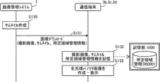
図38に示されているように、画像管理システム7´の作成部73は、記憶・抽出部79によって読み出された所定領域管理情報(画像識別情報)で識別される全天球パノラマ画像における所定領域画像に基づいて、この所定領域画像に関するサムネイルを作成すると共に、この作成したサムネイルを識別するためのサムネイル識別情報も作成する。
As shown in FIG. 38, the
次に、送受信部71は、図18に示されているステップS31と同様に、通信端末3bに対して、図18に示されているステップS29によって読み出された撮影画像と、図18に示されているステップS30によって読み出された所定領域管理情報とを送信するだけでなく、図38に示されているステップS130によって作成されたサムネイル及びサムネイル識別情報を送信する。(ステップS131)。これにより、通信端末3bの送受信部31が、撮影画像及びサムネイル、並びに所定領域管理情報及びサムネイル識別情報を受信することで、撮影画像のダウンロードが終了する。なお、上記ステップS130によって作成されたサムネイル識別情報が、所定領域管理情報の各画像識別情報、所定領域情報、及び関連情報に関連付けられている。
Next, as in step S31 shown in FIG. 18, the transmission /
次に、通信端末3bの記憶・抽出部39は、記憶部1000に図38に示されているステップS131によってダウンロードされた撮影画像及びサムネイルを記憶させると共に、記憶部1000の所定領域管理DB3001に上記ステップS131によってダウンロードされた所定領域管理情報を記憶させる(図38に示されているステップS132)。この所定領域管理DB3001に記憶された所定領域管理情報は、図16と同様の形態の管理テーブルを構成している。
Next, the storage /
次に、通信端末3bの作成部33は、図18に示されているステップS33と同様に、撮影画像に基づいて、図6に示されているような全天球パノラマ画像を作成し、表示制御部34は、通信端末3bのディスプレイ315に全天球パノラマ画像を表示させる(図38に示されているステップS133)。
Next, the
<<本実施形態の主な効果>>
以上説明したように本実施形態によれば、画像管理システム7´側で、一括してサムネイルを作成することができるため、上記第1の実施形態の効果に加え、各通信端末にサムネイルを作成するプログラムをインストールする必要がないという効果を奏する。
<< Main effects of this embodiment >>
As described above, according to the present embodiment, thumbnails can be created collectively on the image management system 7 'side. Therefore, in addition to the effects of the first embodiment, thumbnails are created for each communication terminal. There is an effect that it is not necessary to install a program to be executed.
〔実施形態の補足〕
上記各実施形態における画像処理システム5、及び画像管理システム7は、単一のコンピュータによって構築されてもよいし、各部(機能又は手段)を分割して任意に割り当てられた複数のコンピュータによって構築されていてもよい。
[Supplement of Embodiment]
The
また、上記実施形態の各プログラムが記憶されたCD−ROM等の記録媒体、並びに、これらプログラムが記憶されたHD504は、いずれもプログラム製品(Program Product)として、国内又は国外へ提供されることができる。
In addition, a recording medium such as a CD-ROM in which the programs of the above-described embodiments are stored, and the
更に、上記各実施形態では、図16に示されているように、所定領域管理テーブルの形式で所定領域管理情報を関しているが、これに限るものではなく、図39に示されているように、URLの形式で管理されるようにしてもよい。なお、図39は、リンク情報の内容を示した図である。 Further, in each of the above embodiments, as shown in FIG. 16, the predetermined area management information is related in the form of the predetermined area management table. However, the present invention is not limited to this, and as shown in FIG. Alternatively, it may be managed in the URL format. FIG. 39 is a diagram showing the contents of the link information.
また、上記第1の実施形態では、図25のステップS108により、所定領域管理情報の絞込みを行った後に、ステップS109により、サムネイルを作成しているが、これに限るものではない。例えば、記憶・抽出部39は所定領域管理情報の絞込みを行わずに、表示制御部34が全てのサムネイルが表示するようにしてもよい。
In the first embodiment, thumbnails are created in step S109 after narrowing down the predetermined area management information in step S108 in FIG. 25, but the present invention is not limited to this. For example, the display /
1 撮影装置
3a、3b、3c、3d 通信端末
5 画像処理システム
7 画像管理システム
9 通信ネットワーク
9a、9b、9c、9d 基地局
31 送受信部
32 操作入力受付部(受付手段の一例)
33 作成部(作成手段の一例)
34 表示制御部(表示制御手段の一例)
35 シーン設定部(設定手段の一例)
39 記憶・抽出部(抽出手段の一例)
51 送受信部
52 シーン設定部
71 送受信部
79 記憶・抽出部
315 ディスプレイ(表示手段の一例)
3000 記憶部(記憶手段の一例)
3001 所定領域管理DB
7000 記憶部
7001 画像管理DB
7002 所定領域管理DB
DESCRIPTION OF
33 Creation unit (an example of creation means)
34 Display control unit (an example of display control means)
35 Scene setting section (an example of setting means)
39 Storage / Extraction Unit (Example of Extraction Unit)
51 Transmission /
3000 storage unit (an example of storage means)
3001 Predetermined area management DB
7000 storage unit 7001 image management DB
7002 Predetermined area management DB
Claims (11)
少なくとも前記関連情報を表示手段に表示させる表示制御手段と、
少なくとも前記関連情報の選択を受け付ける受付手段と、を有し、
前記表示制御手段は、前記選択を受け付けられた所定の関連情報に対応する画像識別情報で識別されるパノラマ画像において、前記選択を受け付けられた所定の関連情報に対応する所定領域情報で示される所定領域画像に関するサムネイルを、前記表示手段に表示させ、
前記受付手段は、前記表示されたサムネイルのうち、所定のサムネイルの選択を受け付け、
前記表示制御手段は、前記選択されたサムネイルに対応する所定領域情報で示される所定領域画像を前記表示手段に表示させること
を特徴とする通信端末。 Predetermined area information for indicating a predetermined area in the panoramic image, image identification information for identifying the panoramic image, and related information related to the predetermined area are stored in association with the predetermined area information. Storage means;
Display control means for displaying at least the related information on a display means;
Receiving means for receiving selection of the related information at least ,
In the panorama image identified by the image identification information corresponding to the predetermined related information for which the selection has been received, the display control means is a predetermined area indicated by predetermined area information corresponding to the predetermined related information for which the selection has been received. Display thumbnails related to region images on the display means,
The accepting means accepts a selection of a predetermined thumbnail among the displayed thumbnails,
The communication terminal , wherein the display control means causes the display means to display a predetermined area image indicated by predetermined area information corresponding to the selected thumbnail .
前記受付手段によって受け付けられた所定の関連情報に基づいて前記記憶手段を検索することにより、対応する画像識別情報及び所定領域情報を抽出する抽出手段を有し、
前記表示制御手段は、前記抽出された画像識別情報で識別されるパノラマ画像において、前記抽出された所定領域情報で示されている所定領域画像に関するサムネイルを、前記所定の表示手段に表示させること
を特徴とする通信端末。 The communication terminal according to claim 1 , further comprising:
An extraction unit that extracts the corresponding image identification information and predetermined region information by searching the storage unit based on the predetermined related information received by the reception unit;
The display control means causes the predetermined display means to display a thumbnail relating to the predetermined area image indicated by the extracted predetermined area information in the panoramic image identified by the extracted image identification information. A characteristic communication terminal.
前記抽出手段によって抽出された画像識別情報で識別されるパノラマ画像において、前記抽出手段によって抽出された所定領域情報で示されている所定領域画像に関するサムネイルを作成する作成手段を有することを特徴とする通信端末。 The communication terminal according to claim 2 , further comprising:
In the panorama image identified by the image identification information extracted by the extraction means, the image processing apparatus has a creation means for creating a thumbnail related to the predetermined area image indicated by the predetermined area information extracted by the extraction means. Communication terminal.
前記通信端末は、
少なくとも前記関連情報を表示手段に表示させる表示制御ステップと、
少なくとも前記関連情報の選択を受け付ける受付ステップと、を実行し、
表示制御ステップは、前記選択を受け付けられた所定の関連情報に対応する画像識別情報で識別されるパノラマ画像において、前記選択を受け付けられた所定の関連情報に対応する所定領域情報で示される所定領域画像に関するサムネイルを、前記表示手段に表示させる処理を含み、
前記受付ステップは、前記表示されたサムネイルのうち、所定のサムネイルの選択を受け付ける処理を含み、
前記表示制御ステップは、前記選択されたサムネイルに対応する所定領域情報で示される所定領域画像を前記表示手段に表示させる処理を含むこと
ことを特徴とする表示方法。 Predetermined area information for indicating a predetermined area in the panoramic image, image identification information for identifying the panoramic image, and related information related to the predetermined area are stored in association with the predetermined area information. A communication terminal having a storage means is a display method for displaying an image,
The communication terminal is
A display control step of displaying at least the related information on a display means;
Receiving at least a selection step of the related information ; and
The display control step includes a predetermined area indicated by predetermined area information corresponding to the predetermined related information for which the selection is received in the panoramic image identified by the image identification information corresponding to the predetermined related information for which the selection has been received. Including processing for displaying thumbnails relating to images on the display means;
The receiving step includes a process of receiving a selection of a predetermined thumbnail among the displayed thumbnails,
The display control step includes a process of causing the display means to display a predetermined area image indicated by predetermined area information corresponding to the selected thumbnail .
少なくとも関連情報およびサムネイルの選択を受付ける受付手段と、を有し、Receiving means for receiving selection of at least related information and thumbnails,
前記表示制御手段は、The display control means includes
前記受付手段で選択された関連情報に対応するパノラマ画像において、In the panoramic image corresponding to the related information selected by the receiving means,
当該関連情報に対応するサムネイルを表示手段に表示させ、Display the thumbnail corresponding to the relevant information on the display means,
前記サムネイルのうち、前記受付手段で選択されたサムネイルに対応する所定領域情報の所定領域画像を表示手段に表示させることを特徴とする通信端末。A communication terminal, wherein a predetermined area image of predetermined area information corresponding to a thumbnail selected by the receiving means is displayed on the display means among the thumbnails.
Priority Applications (4)
| Application Number | Priority Date | Filing Date | Title |
|---|---|---|---|
| JP2013053565A JP6186775B2 (en) | 2012-05-31 | 2013-03-15 | Communication terminal, display method, and program |
| US13/902,124 US9756242B2 (en) | 2012-05-31 | 2013-05-24 | Communication terminal, display method, and computer program product |
| EP13169681.7A EP2669822A3 (en) | 2012-05-31 | 2013-05-29 | Communication terminal, display method, and computer program product |
| CN201310210163.8A CN103458180B (en) | 2012-05-31 | 2013-05-30 | Communication terminal and the display packing using communication terminal displays image |
Applications Claiming Priority (3)
| Application Number | Priority Date | Filing Date | Title |
|---|---|---|---|
| JP2012124567 | 2012-05-31 | ||
| JP2012124567 | 2012-05-31 | ||
| JP2013053565A JP6186775B2 (en) | 2012-05-31 | 2013-03-15 | Communication terminal, display method, and program |
Publications (2)
| Publication Number | Publication Date |
|---|---|
| JP2014006880A JP2014006880A (en) | 2014-01-16 |
| JP6186775B2 true JP6186775B2 (en) | 2017-08-30 |
Family
ID=48745616
Family Applications (1)
| Application Number | Title | Priority Date | Filing Date |
|---|---|---|---|
| JP2013053565A Active JP6186775B2 (en) | 2012-05-31 | 2013-03-15 | Communication terminal, display method, and program |
Country Status (4)
| Country | Link |
|---|---|
| US (1) | US9756242B2 (en) |
| EP (1) | EP2669822A3 (en) |
| JP (1) | JP6186775B2 (en) |
| CN (1) | CN103458180B (en) |
Cited By (1)
| Publication number | Priority date | Publication date | Assignee | Title |
|---|---|---|---|---|
| JP2015018013A (en) * | 2013-07-08 | 2015-01-29 | 株式会社リコー | Display controller, program, and recording medium |
Families Citing this family (50)
| Publication number | Priority date | Publication date | Assignee | Title |
|---|---|---|---|---|
| JP6167703B2 (en) | 2013-07-08 | 2017-07-26 | 株式会社リコー | Display control device, program, and recording medium |
| KR20150028066A (en) * | 2013-09-05 | 2015-03-13 | 엘지전자 주식회사 | Mobile terminal and control method thereof |
| JP5835384B2 (en) | 2014-03-18 | 2015-12-24 | 株式会社リコー | Information processing method, information processing apparatus, and program |
| JP5835383B2 (en) | 2014-03-18 | 2015-12-24 | 株式会社リコー | Information processing method, information processing apparatus, and program |
| US9906720B2 (en) | 2014-12-05 | 2018-02-27 | Ricoh Company, Ltd. | Service system, information processing apparatus, and service providing method |
| JP6682821B2 (en) | 2014-12-05 | 2020-04-15 | 株式会社リコー | Service system, information processing device, service providing method |
| EP3232331A4 (en) * | 2014-12-08 | 2017-12-20 | Ricoh Company, Ltd. | Image management system, image management method, and program |
| EP3040835B1 (en) * | 2014-12-31 | 2021-12-01 | Nokia Technologies Oy | Image navigation |
| JP6497965B2 (en) | 2015-02-23 | 2019-04-10 | キヤノン株式会社 | Image processing apparatus and image processing method |
| US9924093B1 (en) * | 2015-05-01 | 2018-03-20 | Hoyos Integrity Corporation | Method and apparatus for displaying panoramic images |
| JP6503881B2 (en) * | 2015-05-20 | 2019-04-24 | 株式会社リコー | Content providing system, information processing apparatus, program, content reproducing method |
| EP3112986B1 (en) | 2015-07-03 | 2020-02-26 | Nokia Technologies Oy | Content browsing |
| CN107925740A (en) * | 2015-07-21 | 2018-04-17 | 株式会社理光 | Image management system, image management method and program |
| JP6613686B2 (en) * | 2015-07-29 | 2019-12-04 | 株式会社リコー | Movie display device, movie display method, and program |
| JP6633862B2 (en) * | 2015-08-04 | 2020-01-22 | キヤノン株式会社 | Information processing apparatus and control method thereof |
| JP2017040687A (en) * | 2015-08-17 | 2017-02-23 | 株式会社リコー | Image display system, information processor, image display method, and program |
| JP6555026B2 (en) * | 2015-09-04 | 2019-08-07 | 株式会社リコー | Information provision system |
| JP6615545B2 (en) * | 2015-09-15 | 2019-12-04 | 株式会社トプコン | Image processing apparatus, image processing method, and image processing program |
| US9767363B2 (en) | 2015-10-30 | 2017-09-19 | Google Inc. | System and method for automatic detection of spherical video content |
| JP6617547B2 (en) * | 2015-12-11 | 2019-12-11 | 株式会社リコー | Image management system, image management method, and program |
| JP6665558B2 (en) | 2016-01-29 | 2020-03-13 | 株式会社リコー | Image management system, image management method, image communication system, and program |
| WO2017145483A1 (en) | 2016-02-24 | 2017-08-31 | 株式会社リコー | Image processing device, image processing system, and program |
| US10652459B2 (en) | 2016-03-07 | 2020-05-12 | Ricoh Company, Ltd. | Information processing system, information processing method, and non-transitory computer-readable storage medium |
| CN108781251A (en) | 2016-03-15 | 2018-11-09 | 株式会社理光 | Image processing apparatus, image processing method and image processing system |
| KR102590132B1 (en) | 2016-03-24 | 2023-10-18 | 삼성전자주식회사 | Display device and controlling method thereof |
| US20170309060A1 (en) * | 2016-04-21 | 2017-10-26 | Honeywell International Inc. | Cockpit display for degraded visual environment (dve) using millimeter wave radar (mmwr) |
| EP3627844A1 (en) * | 2016-05-13 | 2020-03-25 | SONY Corporation | File generation device, file generation method, reproducing device, and reproducing method |
| JP6735644B2 (en) * | 2016-09-20 | 2020-08-05 | キヤノン株式会社 | Information processing apparatus, control method thereof, and computer program |
| KR102632795B1 (en) | 2016-09-21 | 2024-02-02 | 삼성전자주식회사 | Method for displaying navigator related to contents and electronic device for the same |
| JP2018056889A (en) * | 2016-09-30 | 2018-04-05 | 株式会社リコー | Display terminal, display method, and program |
| US10264302B2 (en) * | 2016-09-30 | 2019-04-16 | Ricoh Company, Ltd. | Communication management apparatus, method and computer-readable storage medium for generating image data identification information |
| CN107993276B (en) * | 2016-10-25 | 2021-11-23 | 杭州海康威视数字技术股份有限公司 | Panoramic image generation method and device |
| US10176615B2 (en) * | 2016-12-13 | 2019-01-08 | Topcon Corporation | Image processing device, image processing method, and image processing program |
| KR20180073327A (en) * | 2016-12-22 | 2018-07-02 | 삼성전자주식회사 | Display control method, storage medium and electronic device for displaying image |
| US10417276B2 (en) * | 2017-05-15 | 2019-09-17 | Adobe, Inc. | Thumbnail generation from panoramic images |
| EP3668081A4 (en) * | 2017-08-07 | 2020-07-08 | Sony Corporation | Transmission device, transmission method, reception device, reception method and imaging device |
| JP6793615B2 (en) * | 2017-09-22 | 2020-12-02 | Kddi株式会社 | Display devices, display programs and display systems |
| JP7031228B2 (en) * | 2017-10-26 | 2022-03-08 | 株式会社リコー | Program, image display method, image display system, information processing device |
| JP6503098B1 (en) * | 2018-01-30 | 2019-04-17 | フォージビジョン株式会社 | Image processing apparatus, image processing program and image processing method |
| JP7081473B2 (en) | 2018-03-02 | 2022-06-07 | 株式会社リコー | Imaging optical system, imaging system and imaging device |
| EP3537399B1 (en) | 2018-03-05 | 2021-03-31 | Ricoh Company, Ltd. | Imaging optical system, imaging system, and imaging apparatus |
| US10852503B2 (en) | 2018-03-20 | 2020-12-01 | Ricoh Company, Ltd. | Joint structure |
| JP7124366B2 (en) | 2018-03-20 | 2022-08-24 | 株式会社リコー | Imaging element fixing structure and imaging device |
| JP2019164303A (en) | 2018-03-20 | 2019-09-26 | 株式会社リコー | Optical system and imaging apparatus |
| JP7164831B2 (en) * | 2018-03-30 | 2022-11-02 | 株式会社リコー | Communication management system, communication system, communication method, and program |
| JP7273477B2 (en) | 2018-10-02 | 2023-05-15 | パイオニア株式会社 | Display control device, display control method and display control program |
| JP7268372B2 (en) * | 2019-01-31 | 2023-05-08 | 株式会社リコー | Imaging device |
| JP6679784B2 (en) * | 2019-03-12 | 2020-04-15 | キヤノン株式会社 | Image processing apparatus and image processing method |
| CN111723271A (en) * | 2020-07-15 | 2020-09-29 | 山东省计量科学研究院 | Measurement and weighing and measurement science popularization knowledge electronic museum holographic navigation display system and method |
| WO2023100220A1 (en) * | 2021-11-30 | 2023-06-08 | 日本電信電話株式会社 | Video processing device, method, and program |
Family Cites Families (40)
| Publication number | Priority date | Publication date | Assignee | Title |
|---|---|---|---|---|
| JPH04258825A (en) | 1991-02-12 | 1992-09-14 | Hitachi Maxell Ltd | Tight sticking type optical information recording medium |
| JPH04307483A (en) | 1991-04-04 | 1992-10-29 | Hokkaido Nippon Denki Software Kk | Floppy disk device fault prevention system |
| US6396941B1 (en) * | 1996-08-23 | 2002-05-28 | Bacus Research Laboratories, Inc. | Method and apparatus for internet, intranet, and local viewing of virtual microscope slides |
| US6272235B1 (en) * | 1997-03-03 | 2001-08-07 | Bacus Research Laboratories, Inc. | Method and apparatus for creating a virtual microscope slide |
| JPH10336705A (en) * | 1997-06-02 | 1998-12-18 | Canon Inc | Compound eye camera |
| CN1214614C (en) * | 1998-04-10 | 2005-08-10 | 株式会社理光 | Image processing method, image processing device and recording medium |
| JP2001186334A (en) * | 1999-12-27 | 2001-07-06 | Canon Inc | Device, system and method for picture processing, and storage medium |
| US20020063725A1 (en) * | 2000-11-30 | 2002-05-30 | Virtuallylisted Llc | Method and apparatus for capturing and presenting panoramic images for websites |
| JP4258825B2 (en) | 2001-03-01 | 2009-04-30 | 富士フイルム株式会社 | Electronic camera, image providing system and method thereof |
| JP2003110983A (en) * | 2001-09-28 | 2003-04-11 | Canon Inc | Image pickup device, image management device, image management system, method for controlling the image pickup device, image management method, recording medium and program |
| US20100002070A1 (en) * | 2004-04-30 | 2010-01-07 | Grandeye Ltd. | Method and System of Simultaneously Displaying Multiple Views for Video Surveillance |
| JP2005025548A (en) * | 2003-07-03 | 2005-01-27 | Minolta Co Ltd | Processing device, output method and output program for image with annotation information |
| JP4837248B2 (en) * | 2003-10-29 | 2011-12-14 | 京セラ株式会社 | Image display device and control method of image display device |
| US8427538B2 (en) * | 2004-04-30 | 2013-04-23 | Oncam Grandeye | Multiple view and multiple object processing in wide-angle video camera |
| JP4494196B2 (en) * | 2004-12-27 | 2010-06-30 | 京セラ株式会社 | Image display device |
| JP2007018352A (en) * | 2005-07-08 | 2007-01-25 | Olympus Imaging Corp | Image display device, image display program, image display method and recording medium |
| JP4592099B2 (en) * | 2005-09-29 | 2010-12-01 | キヤノン株式会社 | Image display device and image display method |
| EP1954029B1 (en) * | 2005-11-11 | 2011-04-06 | Sony Corporation | Image processing device, image processing method, program thereof, and recording medium containing the program |
| US8477154B2 (en) * | 2006-03-20 | 2013-07-02 | Siemens Energy, Inc. | Method and system for interactive virtual inspection of modeled objects |
| WO2007124664A1 (en) * | 2006-04-29 | 2007-11-08 | Shanghai Jietu Software Co., Ltd. | Apparatus and method for collecting panorama graph with location information and method for building, annotating and switching panorama electric map service |
| JP5087867B2 (en) | 2006-07-04 | 2012-12-05 | ソニー株式会社 | Information processing apparatus and method, and program |
| JP4307483B2 (en) | 2006-12-22 | 2009-08-05 | キヤノン株式会社 | Imaging apparatus, image display apparatus, control method thereof, and computer program |
| JP4050777B1 (en) * | 2007-04-06 | 2008-02-20 | 株式会社デジタルマックス | Image display system |
| US20100122208A1 (en) * | 2007-08-07 | 2010-05-13 | Adam Herr | Panoramic Mapping Display |
| JP5326910B2 (en) * | 2009-01-20 | 2013-10-30 | ソニー株式会社 | Information processing apparatus, information processing method, and program |
| JP5338498B2 (en) | 2009-06-09 | 2013-11-13 | ソニー株式会社 | Control device, camera system and program used in surveillance camera system |
| WO2011008209A1 (en) | 2009-07-16 | 2011-01-20 | Jiang Gu | Virtual telemicroscope |
| JP5232107B2 (en) | 2009-09-02 | 2013-07-10 | 株式会社ニコンシステム | Image display method, program, image display apparatus, and imaging apparatus |
| JP5385059B2 (en) | 2009-09-07 | 2014-01-08 | 株式会社ニコンシステム | Image display method, program, image display apparatus, and imaging apparatus |
| US8599219B2 (en) * | 2009-09-18 | 2013-12-03 | Adobe Systems Incorporated | Methods and apparatuses for generating thumbnail summaries for image collections |
| US8619098B2 (en) * | 2009-09-18 | 2013-12-31 | Adobe Systems Incorporated | Methods and apparatuses for generating co-salient thumbnails for digital images |
| JP5464955B2 (en) * | 2009-09-29 | 2014-04-09 | 株式会社ソニー・コンピュータエンタテインメント | Panorama image display device |
| KR20110052124A (en) * | 2009-11-12 | 2011-05-18 | 삼성전자주식회사 | Method for generating and referencing panorama image and mobile terminal using the same |
| JP5340895B2 (en) * | 2009-11-24 | 2013-11-13 | 株式会社ソニー・コンピュータエンタテインメント | Image data creation support apparatus and image data creation support method |
| US20120019614A1 (en) * | 2009-12-11 | 2012-01-26 | Tessera Technologies Ireland Limited | Variable Stereo Base for (3D) Panorama Creation on Handheld Device |
| JP2011211696A (en) * | 2010-03-10 | 2011-10-20 | Nikon Corp | Image data processing system, image data processing program, and image data processing apparatus |
| US9183560B2 (en) * | 2010-05-28 | 2015-11-10 | Daniel H. Abelow | Reality alternate |
| JP5134651B2 (en) * | 2010-07-07 | 2013-01-30 | 株式会社ソニー・コンピュータエンタテインメント | Image display device and image display method |
| JP5462094B2 (en) | 2010-07-07 | 2014-04-02 | 株式会社ソニー・コンピュータエンタテインメント | Image processing apparatus and image processing method |
| US20130235084A1 (en) * | 2012-03-12 | 2013-09-12 | Chuan-Wei Wu | Multi-source multiple documents comparison display (presentation or discussion) system |
-
2013
- 2013-03-15 JP JP2013053565A patent/JP6186775B2/en active Active
- 2013-05-24 US US13/902,124 patent/US9756242B2/en active Active
- 2013-05-29 EP EP13169681.7A patent/EP2669822A3/en not_active Ceased
- 2013-05-30 CN CN201310210163.8A patent/CN103458180B/en active Active
Cited By (1)
| Publication number | Priority date | Publication date | Assignee | Title |
|---|---|---|---|---|
| JP2015018013A (en) * | 2013-07-08 | 2015-01-29 | 株式会社リコー | Display controller, program, and recording medium |
Also Published As
| Publication number | Publication date |
|---|---|
| CN103458180A (en) | 2013-12-18 |
| US20130326419A1 (en) | 2013-12-05 |
| US9756242B2 (en) | 2017-09-05 |
| EP2669822A2 (en) | 2013-12-04 |
| CN103458180B (en) | 2017-03-01 |
| JP2014006880A (en) | 2014-01-16 |
| EP2669822A3 (en) | 2015-06-10 |
Similar Documents
| Publication | Publication Date | Title |
|---|---|---|
| JP6186775B2 (en) | Communication terminal, display method, and program | |
| JP6075066B2 (en) | Image management system, image management method, and program | |
| JP6665558B2 (en) | Image management system, image management method, image communication system, and program | |
| JP5920057B2 (en) | Transmission device, image sharing system, transmission method, and program | |
| JP2014112302A (en) | Prescribed area management system, communication method, and program | |
| JP7420126B2 (en) | System, management system, image management method, and program | |
| JP6011117B2 (en) | Reception device, image sharing system, reception method, and program | |
| JP6304300B2 (en) | Transmitting apparatus, communication method, program, and receiving apparatus | |
| JP2018026642A (en) | Image management system, image communication system, image management method, and program | |
| JP6586819B2 (en) | Image management system, image communication system, image management method, and program | |
| JP5942637B2 (en) | Additional information management system, image sharing system, additional information management method, and program | |
| JP6233451B2 (en) | Image sharing system, communication method and program | |
| JP6508288B2 (en) | SYSTEM, IMAGE SHARING SYSTEM, COMMUNICATION METHOD, AND PROGRAM | |
| JP2017182548A (en) | Image management system, image management method, image communication system, and program | |
| JP6665440B2 (en) | Image management system, image management method, image communication system, and program | |
| JP6816403B2 (en) | Image management system, image communication system, image management method, and program | |
| JP2018050123A (en) | Image display system, image display method, and program | |
| JP2016194782A (en) | Image management system, communication terminal, communication system, image management method, and program |
Legal Events
| Date | Code | Title | Description |
|---|---|---|---|
| A621 | Written request for application examination |
Free format text: JAPANESE INTERMEDIATE CODE: A621 Effective date: 20160212 |
|
| A977 | Report on retrieval |
Free format text: JAPANESE INTERMEDIATE CODE: A971007 Effective date: 20161130 |
|
| A131 | Notification of reasons for refusal |
Free format text: JAPANESE INTERMEDIATE CODE: A131 Effective date: 20161206 |
|
| A521 | Request for written amendment filed |
Free format text: JAPANESE INTERMEDIATE CODE: A523 Effective date: 20170206 |
|
| TRDD | Decision of grant or rejection written | ||
| A01 | Written decision to grant a patent or to grant a registration (utility model) |
Free format text: JAPANESE INTERMEDIATE CODE: A01 Effective date: 20170704 |
|
| A61 | First payment of annual fees (during grant procedure) |
Free format text: JAPANESE INTERMEDIATE CODE: A61 Effective date: 20170717 |
|
| R151 | Written notification of patent or utility model registration |
Ref document number: 6186775 Country of ref document: JP Free format text: JAPANESE INTERMEDIATE CODE: R151 |