JP6181567B2 - Sheet storage device and image forming apparatus - Google Patents
Sheet storage device and image forming apparatus Download PDFInfo
- Publication number
- JP6181567B2 JP6181567B2 JP2014016400A JP2014016400A JP6181567B2 JP 6181567 B2 JP6181567 B2 JP 6181567B2 JP 2014016400 A JP2014016400 A JP 2014016400A JP 2014016400 A JP2014016400 A JP 2014016400A JP 6181567 B2 JP6181567 B2 JP 6181567B2
- Authority
- JP
- Japan
- Prior art keywords
- engaging
- engagement
- engaged
- sheet storage
- sheet
- Prior art date
- Legal status (The legal status is an assumption and is not a legal conclusion. Google has not performed a legal analysis and makes no representation as to the accuracy of the status listed.)
- Active
Links
Images


Classifications
-
- B—PERFORMING OPERATIONS; TRANSPORTING
- B65—CONVEYING; PACKING; STORING; HANDLING THIN OR FILAMENTARY MATERIAL
- B65H—HANDLING THIN OR FILAMENTARY MATERIAL, e.g. SHEETS, WEBS, CABLES
- B65H1/00—Supports or magazines for piles from which articles are to be separated
- B65H1/04—Supports or magazines for piles from which articles are to be separated adapted to support articles substantially horizontally, e.g. for separation from top of pile
-
- B—PERFORMING OPERATIONS; TRANSPORTING
- B65—CONVEYING; PACKING; STORING; HANDLING THIN OR FILAMENTARY MATERIAL
- B65H—HANDLING THIN OR FILAMENTARY MATERIAL, e.g. SHEETS, WEBS, CABLES
- B65H1/00—Supports or magazines for piles from which articles are to be separated
- B65H1/26—Supports or magazines for piles from which articles are to be separated with auxiliary supports to facilitate introduction or renewal of the pile
- B65H1/266—Support fully or partially removable from the handling machine, e.g. cassette, drawer
-
- B—PERFORMING OPERATIONS; TRANSPORTING
- B65—CONVEYING; PACKING; STORING; HANDLING THIN OR FILAMENTARY MATERIAL
- B65H—HANDLING THIN OR FILAMENTARY MATERIAL, e.g. SHEETS, WEBS, CABLES
- B65H31/00—Pile receivers
- B65H31/20—Pile receivers adjustable for different article sizes
-
- B—PERFORMING OPERATIONS; TRANSPORTING
- B65—CONVEYING; PACKING; STORING; HANDLING THIN OR FILAMENTARY MATERIAL
- B65H—HANDLING THIN OR FILAMENTARY MATERIAL, e.g. SHEETS, WEBS, CABLES
- B65H9/00—Registering, e.g. orientating, articles; Devices therefor
-
- B—PERFORMING OPERATIONS; TRANSPORTING
- B65—CONVEYING; PACKING; STORING; HANDLING THIN OR FILAMENTARY MATERIAL
- B65H—HANDLING THIN OR FILAMENTARY MATERIAL, e.g. SHEETS, WEBS, CABLES
- B65H2405/00—Parts for holding the handled material
- B65H2405/10—Cassettes, holders, bins, decks, trays, supports or magazines for sheets stacked substantially horizontally
- B65H2405/11—Parts and details thereof
- B65H2405/112—Rear, i.e. portion opposite to the feeding / delivering side
- B65H2405/1122—Rear, i.e. portion opposite to the feeding / delivering side movable linearly, details therefor
-
- B—PERFORMING OPERATIONS; TRANSPORTING
- B65—CONVEYING; PACKING; STORING; HANDLING THIN OR FILAMENTARY MATERIAL
- B65H—HANDLING THIN OR FILAMENTARY MATERIAL, e.g. SHEETS, WEBS, CABLES
- B65H2405/00—Parts for holding the handled material
- B65H2405/10—Cassettes, holders, bins, decks, trays, supports or magazines for sheets stacked substantially horizontally
- B65H2405/11—Parts and details thereof
- B65H2405/114—Side, i.e. portion parallel to the feeding / delivering direction
- B65H2405/1144—Side, i.e. portion parallel to the feeding / delivering direction extendible
-
- B—PERFORMING OPERATIONS; TRANSPORTING
- B65—CONVEYING; PACKING; STORING; HANDLING THIN OR FILAMENTARY MATERIAL
- B65H—HANDLING THIN OR FILAMENTARY MATERIAL, e.g. SHEETS, WEBS, CABLES
- B65H2511/00—Dimensions; Position; Numbers; Identification; Occurrences
- B65H2511/10—Size; Dimensions
-
- B—PERFORMING OPERATIONS; TRANSPORTING
- B65—CONVEYING; PACKING; STORING; HANDLING THIN OR FILAMENTARY MATERIAL
- B65H—HANDLING THIN OR FILAMENTARY MATERIAL, e.g. SHEETS, WEBS, CABLES
- B65H2511/00—Dimensions; Position; Numbers; Identification; Occurrences
- B65H2511/10—Size; Dimensions
- B65H2511/11—Length
-
- B—PERFORMING OPERATIONS; TRANSPORTING
- B65—CONVEYING; PACKING; STORING; HANDLING THIN OR FILAMENTARY MATERIAL
- B65H—HANDLING THIN OR FILAMENTARY MATERIAL, e.g. SHEETS, WEBS, CABLES
- B65H2511/00—Dimensions; Position; Numbers; Identification; Occurrences
- B65H2511/10—Size; Dimensions
- B65H2511/12—Width
-
- B—PERFORMING OPERATIONS; TRANSPORTING
- B65—CONVEYING; PACKING; STORING; HANDLING THIN OR FILAMENTARY MATERIAL
- B65H—HANDLING THIN OR FILAMENTARY MATERIAL, e.g. SHEETS, WEBS, CABLES
- B65H2511/00—Dimensions; Position; Numbers; Identification; Occurrences
- B65H2511/20—Location in space
-
- B—PERFORMING OPERATIONS; TRANSPORTING
- B65—CONVEYING; PACKING; STORING; HANDLING THIN OR FILAMENTARY MATERIAL
- B65H—HANDLING THIN OR FILAMENTARY MATERIAL, e.g. SHEETS, WEBS, CABLES
- B65H2801/00—Application field
- B65H2801/03—Image reproduction devices
- B65H2801/06—Office-type machines, e.g. photocopiers
-
- B—PERFORMING OPERATIONS; TRANSPORTING
- B65—CONVEYING; PACKING; STORING; HANDLING THIN OR FILAMENTARY MATERIAL
- B65H—HANDLING THIN OR FILAMENTARY MATERIAL, e.g. SHEETS, WEBS, CABLES
- B65H2801/00—Application field
- B65H2801/39—Scanning
Description
本発明は、シート収納装置及び画像形成装置に関する。 The present invention relates to a sheet storage device and an image forming apparatus.
特許文献1には、媒体を積載する媒体積載部と、媒体積載部に対して移動可能に設けられ、媒体の端部を規制するガイド部材とを備える媒体積載装置が示されている。この媒体積載装置では、ガイド部材に設けられた複数のロック突部が、媒体積載部の底部に設けられた複数のロック突部と係合することで、媒体載置部の所定の位置にガイド部材が固定される。 Patent Document 1 discloses a medium stacking device including a medium stacking unit for stacking a medium, and a guide member that is provided so as to be movable with respect to the medium stacking unit and regulates an end of the medium. In this medium stacking apparatus, the plurality of lock protrusions provided on the guide member are engaged with the plurality of lock protrusions provided on the bottom of the medium stacking section, so that the guide is placed at a predetermined position on the medium stacking section. The member is fixed.
特許文献2には、シート材を積載する中板と、中板上に積載されたシート材の後端を規制する後端規制板とを備えるシート材給送装置が示されている。このシート材給送装置では、ラックを有するガイド部材が中板上に取り付けられ、ラックを有するレバーが後端規制板に取り付けられ、レバーのラックがガイド部材のラックと付勢バネによりかみ合い、ラックのピッチ単位で後端規制板を自由な位置にロックすることができる。また、付勢バネの一方の端部が、ガイド部材上の凹部と対向し、弾性をもって係脱可能に構成され、後端規制板をスライドさせたときに、バネ端部が凹部に入り込むことによって、使用者に定型サイズのロック位置をクリック感で知らしめることができる。 Patent Document 2 discloses a sheet material feeding device that includes a middle plate on which sheet materials are stacked, and a rear end regulating plate that regulates the rear end of the sheet material stacked on the middle plate. In this sheet material feeding device, a guide member having a rack is mounted on an intermediate plate, a lever having a rack is mounted on a rear end regulating plate, and the rack of the lever is engaged with the rack of the guide member by a biasing spring, The rear end regulating plate can be locked at a free position in units of pitch. Also, one end of the biasing spring is opposed to the recess on the guide member and is configured to be elastically engageable and disengageable. When the rear end regulating plate is slid, the spring end enters the recess. , The user can be informed with a click feeling of the standard size lock position.
ところで、用紙等のシートを収納するシート収納部と、シート収納部に対して移動可能に設けられ、シートの位置を規制する規制部材と、規制部材の位置を保持する機構とを備えるシート収納装置では、規制部材の保持を解除する際の負荷を低減したいという要望がある。例えば、特許文献1に記載の技術では、ガイド部材に設けられた複数のロック突部と、媒体積載部に設けられた複数のロック突部とが一対一で対応しているので、ロック突部同士の接触面積が大きく、係合を解除する際の負荷が大きい。 By the way, a sheet storage device including a sheet storage unit that stores sheets such as paper, a restriction member that is movably provided with respect to the sheet storage unit, and that restricts the position of the sheet, and a mechanism that holds the position of the restriction member Then, there is a desire to reduce the load when releasing the holding of the regulating member. For example, in the technique described in Patent Document 1, a plurality of lock protrusions provided on the guide member and a plurality of lock protrusions provided on the medium stacking unit correspond one-to-one. The contact area between them is large, and the load when releasing the engagement is large.
本発明は、シート収納部に収納されるシートの位置を規制する規制部材の保持を解除する際の負荷を低減することができるシート収納装置及び画像形成装置を提供することを目的とする。 SUMMARY An advantage of some aspects of the invention is that it provides a sheet storage device and an image forming apparatus that can reduce a load when releasing a holding member that restricts the position of a sheet stored in a sheet storage unit.
本発明に係るシート収納装置は、シートを収納するシート収納部と、前記シート収納部に対して所定の移動方向に移動可能に設けられ、前記シート収納部に収納されたシートの前記移動方向の位置を規制する規制部材と、前記規制部材に設けられた第1の係合部と、前記シート収納部に設けられ、前記第1の係合部と係合することにより前記規制部材を前記移動方向における複数の保持位置で保持する第1の被係合部とを備え、前記第1の係合部および前記第1の被係合部のうちの一方は、前記移動方向に第1の間隔で配列された複数の係合溝を有し、前記第1の係合部および前記第1の被係合部のうちの他方は、前記移動方向に第2の間隔で配列され、前記複数の係合溝と係合する複数の係合突起を有し、前記複数の保持位置の間隔は前記第1の間隔と等しく、前記第2の間隔は前記第1の間隔の2以上の整数倍であることを特徴とする。 A sheet storage device according to the present invention is provided with a sheet storage unit that stores a sheet, and a sheet storage unit that is movable with respect to the sheet storage unit in a predetermined movement direction. A restricting member for restricting the position; a first engaging portion provided on the restricting member; and a first engaging portion provided on the sheet storage portion, wherein the restricting member is moved by engaging with the first engaging portion. A first engaged portion that is held at a plurality of holding positions in the direction, and one of the first engaged portion and the first engaged portion has a first interval in the moving direction. The other of the first engaging portion and the first engaged portion is arranged at a second interval in the movement direction, and the plurality of engaging grooves are arranged in the moving direction. A plurality of engaging protrusions that engage with the engaging grooves, and the intervals between the plurality of holding positions are Equal to 1 interval, wherein the second interval is 2 or more integer multiples of the first distance.
本発明に係るシート収納装置は、シートを収納するシート収納部と、前記シート収納部に対して所定の移動方向に移動可能に設けられ、前記シート収納部に収納されたシートの前記移動方向の位置を規制する規制部材と、前記規制部材に設けられた第1および第2の係合部と、前記シート収納部に設けられ、それぞれ前記第1および第2の係合部と係合することにより前記規制部材を前記移動方向における所定の位置で保持する第1および第2の被係合部と、前記規制部材に対して回動軸を中心として回動可能に設けられ、一端側に作用点部を有するレバーとを備え、前記第1の係合部は、前記レバーが回動すると前記作用点部が当接する当接面を有し、前記第1の係合部は、第1の当接部を有し、前記第2の係合部は、前記第1の当接部と対向する第2の当接部を有し、前記第1および第2の係合部は、前記レバーが回動すると、前記レバーから外力を受けて前記第1の係合部が前記第1の被係合部から離間する方向に直線移動することにより、前記第1の係合部と前記第1の被係合部との係合が解除された後、前記第1の当接部が前記第2の当接部に当接し、前記第1の係合部の直線移動による力を受けて前記第2の係合部が前記第2の被係合部から離間する方向に直線移動し、前記第2の係合部と前記第2の被係合部との係合が解除されるように構成されていることを特徴とする。 A sheet storage device according to the present invention is provided with a sheet storage unit that stores a sheet, and a sheet storage unit that is movable with respect to the sheet storage unit in a predetermined movement direction. A restricting member for restricting the position, first and second engaging portions provided on the restricting member, and provided on the sheet storage portion and engaging with the first and second engaging portions, respectively; The first and second engaged portions that hold the restricting member at a predetermined position in the moving direction, and are provided so as to be rotatable about a rotation axis with respect to the restricting member and act on one end side. A lever having a point , and the first engagement portion has a contact surface with which the action point portion comes into contact when the lever rotates, and the first engagement portion An abutting portion, and the second engaging portion includes the first abutting portion and A second contact portion for direction, said first and second engaging portions, when the lever is pivoted, said by an external force from the lever first engagement portion is the first After the engagement between the first engagement portion and the first engaged portion is released by linear movement in a direction away from the engaged portion, the first contact portion is Abutting on the second abutting portion, receiving a force due to linear movement of the first engaging portion, and linearly moving in a direction in which the second engaging portion is separated from the second engaged portion; The second engagement portion and the second engaged portion are configured to be disengaged from each other.
本発明に係る画像形成装置は、上記のいずれかのシート収納装置と、前記シート収納装置に収納されたシートを送り出すシート送出部と、前記シート送出部により送り出されたシート上に画像を形成する画像形成部とを含むことを特徴とする。 An image forming apparatus according to the present invention forms an image on any of the sheet storage devices described above, a sheet delivery unit that sends out the sheets stored in the sheet storage device, and a sheet that is sent out by the sheet delivery unit. an image forming unit, characterized in including it.
本発明によれば、シート収納部に収納されるシートの位置を規制する規制部材の保持を解除する際の負荷を低減することができる。 According to the present invention, it is possible to reduce the load when releasing the holding of the regulating member that regulates the position of the sheet stored in the sheet storage unit.
以下、本発明の実施の形態を図面に従って説明する。
図1は、本実施の形態に係るシート収納装置を含む画像形成装置1の構成を示す概略図である。この画像形成装置1は、シート収納装置に収納されたシート上に画像を形成する装置であり、本例では、電子写真方式のカラープリンタである。
Hereinafter, embodiments of the present invention will be described with reference to the drawings.
FIG. 1 is a schematic diagram illustrating a configuration of an image forming apparatus 1 including a sheet storage device according to the present embodiment. The image forming apparatus 1 is an apparatus that forms an image on a sheet stored in a sheet storage apparatus. In this example, the image forming apparatus 1 is an electrophotographic color printer.
画像形成装置1は、シートを収納するシート収納装置としての給紙カセット100と、給紙カセット100に収納されたシートを送り出すシート送出部としての用紙繰り出し部200と、用紙繰り出し部200により送り出されたシート上に画像を形成する画像形成部400とを有する。
The image forming apparatus 1 is fed by a
給紙カセット100は、シートとしての印刷媒体または印刷用紙(以下、単に「用紙」という)101を収納する。具体的には、給紙カセット100の内部には、用紙101が積層状態で載置される。給紙カセット100は、画像形成装置1の装置本体2に着脱自在に装着され、その下端部は固定台102a、102bに支持される。給紙カセット100の内部には、支持軸11aによって回動可能に支持された用紙載置板11が設けられ、この用紙載置板11上に用紙101が積載される。給紙カセット100の繰り出し側には、支持軸103aに回転可能にリフトアップレバー103が配置され、支持軸103aは、モータ104と接離可能に係合する。給紙カセット100が装置本体2に挿入されると、リフトアップレバー103とモータ104とが係合し、図示されない制御部がモータ104を駆動する。これによりリフトアップレバー103が回転することによって、リフトアップレバー103の先端部が用紙載置板11の底部を持ち上げ、用紙載置板11に積載された用紙101が上昇する。そして、用紙101がある高さまで上昇するとピックアップローラ202に当接し、これを上昇検知部201が検知する。制御部は、上昇検知部201が検知した情報に基づいてモータ104を停止させる。ピックアップローラ202は、接触した状態で対に配置されたフィードローラ203およびリタードローラ204とともに用紙繰り出し部200を構成している。用紙繰り出し部200は、給紙カセット100とともに給紙装置3を構成している。
The
ピックアップローラ202およびフィードローラ203は、図示しないモータによって図中矢印方向に回転駆動され、かつ内部に図示せぬワンウェイクラッチ機構を内臓しているため回転駆動が停止した場合でも図中矢印方向には空転可能となっており、また、リタードローラ204は、図示しないトルク発生手段によって、図中矢印方向のトルクを発生させている。従って、ピックアップローラ202は、給紙カセット100内から当接した用紙101を引き出し、フィードローラ203およびリタードローラ204は、例えば、複数の用紙101が同時に引き出された場合にも、1枚ずつ用紙101を順次搬送経路に繰り出す。
The
用紙101の搬送方向(図中矢印A方向)における、用紙繰り出し部200の下流側には、順に用紙センサ301、用紙101の斜行を規制する搬送ローラ対302、次の搬送ローラ対304の駆動タイミングを検出する用紙センサ303、画像形成部400に用紙101を送り込む搬送ローラ対304および305、ならびに画像形成部400での書き込みタイミングを取るための書き込みセンサ306が配置されている。これらの搬送ローラ対302、304、および305には、図示されない搬送駆動モータから図示されないギヤ等の駆動伝達手段を経由して動力が伝達される。
In the transport direction of the paper 101 (in the direction of arrow A in the figure), on the downstream side of the
図1における画像形成装置1の右側面には、用紙積載板604に積載された用紙606を給紙するマルチパーパストレイ(MPT)600が設けられている。MPT600は、用紙606を積載する用紙積載板604、用紙606に接触して用紙606を繰り出すピックローラ602、繰り出された用紙606を装置本体2の搬送経路に送り出す給紙ローラ601、繰り出された用紙を1枚に分離するために給紙ローラ601に付勢され当接するリタードローラ603などからなる。
A multi-purpose tray (MPT) 600 that feeds
画像形成部400は、イエロー、マゼンタ、シアン、およびブラックの各色の画像をそれぞれ形成する4つのプロセスユニット400Y、400M、400C、400Kを有し、これらが中間転写ベルトユニット700の上方に配置されている。これらのプロセスユニットの内部構成は共通しているため、ブラックのプロセスユニット400Kを例にとり、プロセスユニットの内部構成を説明する。
The
プロセスユニット400Kには、感光体ドラム401が図中矢印方向に回転可能に配置され、この感光体ドラム401の周囲には、その回転方向上流側から順に、感光体ドラム401の表面に電荷を供給して帯電させる帯電ローラ402、帯電された感光体ドラム401の表面に選択的に光を照射して静電潜像を形成する露光装置850が配置される。さらに、静電潜像が形成された感光体ドラム401の表面に、ブラックのトナーを付着させてトナー像を形成する現像ローラ404、感光体ドラム401上のトナー像を転写した際に残留した転写残トナーを除去するドラムクリーニング部405が配置される。トナー収納部406Kは、トナーを収納して現像ローラ404にこのトナーを供給する。なお、これらプロセスユニットに含まれるドラムおよびローラは、図示されない駆動源からギヤなどを経由して伝達される動力によって回転する。
In the
中間転写ベルトユニット700は、画像形成部400により形成されたトナー像を、給紙カセット100から供給された用紙101またはMPT600から供給された用紙606に転写する。中間転写ベルトユニット700は、中間転写ベルト701と、図示せぬ駆動部により駆動されるドライブローラ702、コイルスプリング等の付勢部材708により付勢されて中間転写ベルト701に張力を付与するテンションローラ703、中間転写ベルト701の内側に配置される2次転写バックアップローラ704、および中間転写ベルト701を挟んで2次転写バックアップローラ704と対向して配置される2次転写ローラ707を有する。中間転写ベルト701は、ドライブローラ702、テンションローラ703、および2次転写バックアップローラ704により張架され、ドライブローラ702により駆動される。さらに、中間転写ベルトユニット700は、中間転写ベルト701を挟んで各プロセスユニットの感光体ドラム401と対向して配置された4つの1次転写ローラ705と、中間転写ベルト701上に残ったトナーを除去するベルトクリーニング部706とを有する。上記構成において、4つの1次転写ローラ705は、所定の電圧を付加することにより、対応する感光体ドラム401上に形成されたトナー像を中間転写ベルト701上に転写し、2次転写ローラ707は、中間転写ベルト701上に転写された各色のトナー像を用紙101または606上に転写する。トナー像が転写された用紙101または606は、定着部500に搬送される。
The intermediate
定着部500は、内部に熱源となるハロゲンランプ503aを備え、表面が弾性体で形成されたアッパローラ501と、内部に熱源となるハロゲンランプ503bを備え、表面が弾性体で形成されたロワローラ502とのローラ対を有し、画像形成部400より送り出された用紙101または606上のトナー像に熱と圧力を付与してトナー像を融解し、この像を用紙101または606に定着させる。
The fixing
トナー像が定着された用紙101または606は、排出ローラ対504a、504b、504c、504dによって搬送され、スタッカ部505に排出される。これら排出ローラ対には、図示されない駆動源から図示されない駆動伝達手段を経由して動力が伝達される。定着部500の出力部に配置された用紙センサ506は、排出ローラ対504a、504b、504c、504dの駆動タイミングを検出する。
The
なお、ここでは、図1に示されるように、用紙101の搬送方向(図中矢印A方向)に直交し、かつ給紙カセット100内の用紙101の表面に平行な方向にZ軸をとり、給紙カセット100の上下方向(または用紙101の積載方向)にY軸をとり、Z方向およびY方向の両方と直交する方向にX軸をとる。X、Y、およびZ軸は、他の図面にも示されている。以下の説明では、X、Y、およびZ軸に平行な方向をそれぞれ「X方向」、「Y方向」、および「Z方向」という。X方向のうち、用紙101の搬送方向側の方向を「+X方向」、その反対方向を「−X方向」という。Y方向のうち、上方向を「+Y方向」、下方向を「−Y方向」という。Z方向のうち、給紙カセット100が装置本体2に挿入される方向(または給紙カセット100内の用紙101の左端側の方向)を「+Z方向」、その反対方向を「−Z方向」という。
Here, as shown in FIG. 1, the Z axis is taken in a direction perpendicular to the transport direction of the paper 101 (the direction of arrow A in the figure) and parallel to the surface of the
以下、図2から図8を用いて、本実施の形態に係る給紙カセット100の構成を詳細に説明する。
Hereinafter, the configuration of the
図2(a)および(b)は、それぞれ給紙カセット100の構成を示す平面図および斜視図である。
FIGS. 2A and 2B are a plan view and a perspective view, respectively, showing the configuration of the
図2(a)および(b)に示されるように、給紙カセット100は、シート収納部としてのカセット本体10、フロント側用紙ガイド(以下、「フロントガイド」という)20、リア側用紙ガイド(以下、「リアガイド」という)30、およびテール側用紙ガイド(以下、「テールガイド」という)40を備える。
2A and 2B, the
カセット本体10は、用紙101を収納する容器である。カセット本体10内には、用紙101を積載する用紙載置板11が設置される。具体的には、カセット本体10は、XおよびZ方向に延在する矩形平板状の底面部10aを有し、この底面部10a上に用紙載置板11が可動に取り付けられる。カセット本体10の手前側(−Z方向側)には、カセットカバー12が着脱自在に取り付けられている。カセットカバー12には、給紙カセット100の着脱時に掴むための持ち手が設けられている。
The
フロントガイド20、リアガイド30、およびテールガイド40は、カセット本体10に収納された用紙101をガイドするガイド部材であり、カセット本体10内に設置される。フロントガイド20、リアガイド30、およびテールガイド40は、底面部10aに所定方向に移動可能に取り付けられる。
The
フロントガイド20およびリアガイド30は、用紙101の幅方向(Z方向)に移動可能に設置され、用紙101の幅方向の端部をガイドする。フロントガイド20およびリアガイド30は、互いにZ方向に対向するように配置される。フロントガイド20は、−Z方向側に配置され、用紙101の−Z方向側の端部の位置を規制する規制面20aを有する。リアガイド30は、+Z方向側に配置され、用紙101の+Z方向側の端部の位置を規制する規制面30aを有する。テールガイド40は、用紙101の長さ方向(X方向)に移動可能に設置され、用紙101の搬送方向における後端部(−X方向側の端部)の位置を規制する。
The
フロントガイド20、リアガイド30、およびテールガイド40は、それぞれ、収納される用紙101のサイズに応じた所定の位置に固定可能に構成されている。所定の位置としては、A4やA3などの定形サイズの用紙101に対応する位置や、それ以外のサイズである不定形サイズの用紙101に対応する位置がある。ユーザは、フロントガイド20、リアガイド30、およびテールガイド40の位置を、収納される用紙101に対応する位置に合わせることで、給紙カセット100内に定形サイズの用紙101や、不定形サイズの用紙101を給紙可能に収納することができる。
The
なお、ここでは、フロントガイド20およびリアガイド30には、それぞれZ方向に延在するラックギヤ20bおよび30bが設けられ、カセット本体10の底面部10aには、ラックギヤ20bおよび30bと噛合する図示されないピニオンギヤが設けられている。そして、ラックギヤ20bおよび30bとピニオンギヤとの作用により、フロントガイド20およびリアガイド30のうちの一方のガイドの移動に伴って、他方のガイドが一方のガイドと反対方向に同じ移動量だけ移動する。これにより、フロントガイド20の規制面20aとリアガイド30の規制面30aとのZ方向の中心位置は一定に維持される。
Here, rack gears 20b and 30b extending in the Z direction are provided on the
図3(a)および(b)は、それぞれカセット本体10の構成を示す平面図および部分拡大図である。
FIGS. 3A and 3B are a plan view and a partially enlarged view showing the configuration of the
図3(a)および(b)に示されるように、カセット本体10には、フロントガイド20を所定の位置に保持(または固定)するための第1の被係合部13および第2の被係合部14が設けられている。
As shown in FIGS. 3A and 3B, the
第1の被係合部13は、フロントガイド20側に設けられる後述の第1の係合部22と係合することにより、フロントガイド20をZ方向における複数の保持位置で保持する。本例では、第1の被係合部13は、Z方向に等間隔で配列された複数の係合突起としての係合爪13aを有する。複数の係合爪13aは、不定形サイズの用紙101が収納される場合にフロントガイド20を保持するための不定形サイズ用の係合爪群である。第1の被係合部13は、様々なサイズの用紙に対応することができるように、Z方向に長く延在する。
The first engaged
第2の被係合部14は、フロントガイド20側に設けられる後述の第2の係合部24と係合することにより、フロントガイド20をZ方向における所定の位置で保持する。本例では、第2の被係合部14は、Z方向に配列された複数の係合穴(または係合溝)14aを有する。複数の係合穴14aは、定形サイズの用紙101が収納される場合にフロントガイド20を保持するための定形サイズ用の係合穴群であり、A4やA3などの複数種類の定形サイズの用紙101に対応する複数の位置に設けられている。なお、本例では係合穴14aが複数設けられているが、係合穴14aは1つだけ設けられてもよい。
The second engaged
図4(a)および(b)は、それぞれフロントガイド20の構成を示す背面図および分解斜視図である。
4A and 4B are a rear view and an exploded perspective view showing the configuration of the
図4(a)および(b)に示されるように、フロントガイド20は、規制部材としてのガイド本体21、第1の係合部22、第1の付勢部材23、第2の係合部24、第2の付勢部材25、およびレバー26を有する。
As shown in FIGS. 4A and 4B, the
ガイド本体21は、カセット本体10に対して所定の移動方向(ここではZ方向)に移動可能に設けられ、カセット本体10に収納された用紙101の位置を規制する部材である。ガイド本体21は、用紙101の端部を規制する規制面20aを有する規制部21aと、規制部21aをカセット本体10上に立てた状態で支持する支持部21bと、上記ラックギヤ20bを有するラック部21cとを備える。
The guide
第1の係合部22は、カセット本体10側の第1の被係合部13と係合するようにガイド本体21に設けられている。本例では、第1の係合部22は、Z方向に等間隔で配列され、第1の被係合部13の複数の係合爪13aと係合する複数の係合溝22aを有する。複数の係合溝22aは、第1の係合部22の−Y方向側の端部(下端部)に設けられている。複数の係合溝22aは、不定形サイズの用紙101が収納される場合にフロントガイド20を保持するための不定形サイズ用の係合溝群である。第1の係合部22は、第1の被係合部13のZ方向における一部と係合するものであり、第1の被係合部13よりも短い部材である。第1の係合部22は、第1の被係合部13に対して接近する方向および離間する方向に移動可能に設けられる。具体的には、第1の係合部22は、第1の被係合部13と対向する位置に、ガイド本体21に対してY方向に移動可能に取り付けられている。
The first engaging
第1の付勢部材23は、第1の係合部22を第1の被係合部13に向けて付勢する。具体的には、第1の付勢部材23は、ガイド本体21と第1の係合部22との間に配置され、第1の係合部22を−Y方向に付勢する。第1の付勢部材23は、例えばコイルばねである。
The first urging
第2の係合部24は、カセット本体10側の第2の被係合部14と係合するようにガイド本体21に設けられている。本例では、第2の係合部24は、第2の被係合部14の複数の係合穴14aのいずれかと係合する係合突起としての係合ピン24aを有する。係合ピン24aは、第2の係合部24の−Y方向側の端部(下端部)に設けられている。係合ピン24aは、定形サイズの用紙101が収納される場合にフロントガイド20を保持するための定形サイズ用の係合部材である。第2の係合部24は、第2の被係合部14に対して接近する方向および離間する方向に移動可能に設けられる。具体的には、第2の係合部24は、第2の被係合部14と対向する位置に、ガイド本体21に対してY方向に移動可能に取り付けられている。
The second engaging
第2の付勢部材25は、第2の係合部24を第2の被係合部14に向けて付勢する。具体的には、第2の付勢部材25は、ガイド本体21と第2の係合部24との間に配置され、第2の係合部24を−Y方向に付勢する。第2の付勢部材25は、例えばコイルばねである。
The
レバー26は、フロントガイド20の保持を解除するための操作部材である。レバー26は、ガイド本体21に対して回動可能または揺動可能に設けられており、操作力を受けて回動または揺動することにより、第1の係合部22に外力を与える。この外力によって第1の係合部22が+Y方向に移動し、これに連動して第2の係合部24が+Y方向に移動することにより、第1の係合部22および第2の係合部24の係合が解除される。
The
本実施の形態では、フロントガイド20の保持を解除する際の負荷を軽減する観点より、第1の係合部22および第1の被係合部13は、以下のように構成されている。
In the present embodiment, the first engaging
図5は、第1の係合部22と第1の被係合部13とが係合している状態を示す断面図である。図5に示されるように、複数の係合溝22aはZ方向に第1の間隔D1で配列され、複数の係合爪13aはZ方向に第2の間隔D2で配列され、第2の間隔D2は第1の間隔D1の2倍となっている。すなわち、複数の係合爪13aの設置間隔D2は、複数の係合溝22aの設置間隔D1の2倍となっている。本構成において、フロントガイド20(またはガイド本体21)が保持される複数の保持位置の間隔、すなわちフロントガイド20を保持可能な位置の間隔は、第1の間隔D1と等しい。第1の間隔D1は、適宜設定されればよいが、例えば1mm程度である。
FIG. 5 is a cross-sectional view showing a state where the first engaging
また、本実施の形態では、第1の係合部22および第2の係合部24は、以下のように構成されている。
Moreover, in this Embodiment, the
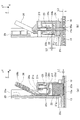
図6(a)および(b)は、第1の係合部22および第2の係合部24が両方とも係合している状態を示す図である。図7(a)および(b)は、第1の係合部22および第2の係合部24のうち第2の係合部24のみが係合している状態を示す図である。図8(a)および(b)は、第1の係合部22および第2の係合部24が両方とも係合していない状態を示す図である。図6(a)、図7(a)、および図8(a)は、第1の係合部22のX方向の中心位置でY−Z平面で切断し、−X方向側から見たときの、カセット本体10およびフロントガイド20の断面図である。図6(b)、図7(b)、および図8(b)は、第2の係合部24のX方向の中心位置でY−Z平面で切断し、−X方向側から見たときの、カセット本体10およびフロントガイド20の断面図である。
FIGS. 6A and 6B are views showing a state where both the first engaging
第1の係合部22および第2の係合部24は、レバー26からの外力を受けて第1の係合部22が第1の被係合部13から離間する方向に移動することにより、第1の係合部22と第1の被係合部13との係合が解除された後、第1の係合部22の移動による力を受けて第2の係合部24が第2の被係合部14から離間する方向に移動し、第2の係合部24と第2の被係合部14との係合が解除されるように構成されている。
The first engaging
具体的には、第1の係合部22は、第2の係合部24に力を付与するための当接面22bを有し、第2の係合部24は、第1の係合部22から力を受けるための当接面24bを有する。図6(a)および(b)に示されるように、第1の係合部22および第2の係合部24が両方とも係合している場合には、2つの当接面22bおよび24bは互いに離間している。そして、第1の係合部22が外力によって+Y方向(上方向)に移動する際、第1の係合部22の係合が解除された後、図7(a)および(b)に示されるように、第1の係合部22の当接面22bが第2の係合部24の当接面24bに当接して+Y方向の力を付与する。この力によって第2の係合部24が+Y方向に移動し、図8(a)および(b)に示されるように、第2の係合部24の係合が解除される。
Specifically, the
以下、フロントガイド20を保持する機構について、より詳細に説明する。
まず、主に図6(a)を参照して、第1の係合部22および第1の被係合部13に関する構成について説明する。
Hereinafter, the mechanism for holding the
First, the configuration relating to the first engaging
図6(a)では、第1の係合部22の複数の係合溝22aと、第1の被係合部13の複数の係合爪13aとが係合している。このとき、係合爪13aは、Y方向において所定の長さL1だけ係合溝22aに進入している。
In FIG. 6A, the plurality of engaging
係合爪13aは、先端に向かって細くなるテーパ形状を有し、係合溝22aは、先端に向かって広くなるテーパ形状を有する。これにより、係合および係合解除する際の第1の係合部22の移動方向の自由度が大きくなっており、係合および係合解除し易くなっている。
The engaging
第1の被係合部13は、樹脂製であり、カセット本体10と一体に形成されている。ただし、第1の被係合部13は、他の材料で形成されてもよく、カセット本体10に取り付けられてもよい。第1の係合部22は、第1の被係合部13よりも強度が高い樹脂で形成されている。ただし、第1の係合部22は、他の材料で形成されてもよい。
The first engaged
第1の係合部22は、ガイド本体21に設けられた案内部21dに収納されて案内される。案内部21dは、第1の係合部22を収容する内部空間21eと、この内部空間21eを画定する内壁21fとを有する。内壁21fは、第1の係合部22のXおよびZ方向の位置を規制し、第1の係合部22のY方向の移動を案内する。また、案内部21dは、第1の係合部22の−Y方向への移動を規制する突き当て面21gを有し、この突き当て面21gは、第1の係合部22に設けられた突き当て面22cと突き当たることにより、第1の係合部22の−Y方向へのそれ以上の移動を阻止する。内壁21fと第1の係合部22との間には隙間が設けられており、内部空間21e内において、第1の係合部22のXおよびZ方向の移動ならびにY方向に対する傾斜が、所定の範囲で許容される。すなわち、第1の係合部22は、案内部21dに緊密に収容されているのではなく、ガイド本体21に対して揺動可能に収容されている。この構成により、係合および係合解除する際、第1の係合部22は、移動し易い位置および方向に動くことができ、係合および係合解除し易くなっている。
The first engaging
また、第1の係合部22の+Y方向側の端部には、第1の付勢部材23からの付勢力を受ける被付勢面22dが設けられており、ガイド本体21には、第1の係合部22の+Y方向側に、第1の付勢部材23を支持する支持面21hが設けられている。被付勢面22dと支持面21hとの間に第1の付勢部材23が配置される。
Further, a
さらに、第1の係合部22は、レバー26と当接してレバー26から外力を受けるレバー当接面22eと、第2の係合部24に押圧力を付与するための当接面22b(図6(b)参照)とを有する。
Further, the
次に、主に図6(b)を参照して、第2の係合部24および第2の被係合部14に関する構成について説明する。
Next, a configuration related to the second engaging
図6(b)では、第2の係合部24の係合ピン24aと、第2の被係合部14の複数の係合穴14aのうちの1つとが係合している。このとき、係合ピン24aは、Y方向において所定の長さL2だけ係合穴14aに進入している。定形サイズの用紙が収納される場合にフロントガイド20がしっかりと固定されるように、係合ピン24aは係合穴14aに深く挿入され、長さL2は長さL1よりも大きい。
In FIG. 6B, the
係合ピン24aおよび係合穴14aは、いずれもY方向と平行に延在し、テーパは付けられていない。これにより、第1の係合部22と比較して、係合および係合解除する際の第2の係合部24の移動方向の自由度が小さくなっており、係合および係合解除し難くなっている。
Both the
第2の被係合部14は、金属製であり、カセット本体10に取り付けられている。ただし、第2の被係合部14は、他の材料で形成されてもよく、カセット本体10と一体に形成されてもよい。第2の係合部24も金属製であるが、他の材料で形成されてもよい。
The second engaged
第2の係合部24は、ガイド本体21に設けられた案内部21iに収納されて案内される。案内部21iは、第2の係合部24を収容する内部空間21jと、この内部空間21jを画定する内壁21kとを有する。内壁21kは、第2の係合部24のXおよびZ方向の位置を規制し、第2の係合部24のY方向の移動を案内する。内壁21kと第2の係合部24との間には僅かな隙間が設けられているが、この隙間は内壁21fと第1の係合部22との隙間と比べて小さく、第2の係合部24は案内部21iに緊密に収容されている。これにより、第2の係合部24が第2の被係合部14と係合した場合に、ガイド本体21の位置がしっかりと固定される。
The
また、第2の係合部24の+Y方向側の端部には、第2の付勢部材25からの付勢力を受ける被付勢面24cが設けられており、ガイド本体21には、第2の係合部24の+Y方向側に、第2の付勢部材25を支持する支持面21lが設けられている。被付勢面24cと支持面21lとの間に第2の付勢部材25が配置される。
Further, a
さらに、第2の係合部24は、第1の係合部22から押圧力を受けるための当接面24bを有する。
Further, the
次に、第1の係合部22の当接面22bおよび第2の係合部24の当接面24bの配置について説明する。
Next, the arrangement of the
図6(a)および(b)に示されるように、第1の係合部22および第2の係合部24が両方とも係合している状態において、当接面24bは、当接面22bから+Y方向に所定距離L3だけ離れた位置に配置されている。距離L3は、長さL1よりも所定距離L4だけ大きく、L3=L1+L4である。
As shown in FIGS. 6A and 6B, in the state where both the
したがって、図6(a)および(b)の状態から、第1の係合部22が+Y方向に距離L1だけ移動すると、第1の係合部22と第1の被係合部13との係合が解除され、さらに第1の係合部22が+Y方向に距離L4だけ移動すると、図7(a)および(b)に示される状態となり、当接面22bが当接面24bと当接する。このとき、第2の係合部24は、第2の被係合部14と係合したままである。第1の係合部22は、当接面22bと当接面24bとが当接した位置から、+Y方向に所定距離L5だけ移動可能に構成されている。距離L5は、長さL2よりも所定距離L6だけ大きく、L5=L2+L6である。
Therefore, when the first engaging
したがって、図7(a)および(b)の状態から、第1の係合部22が+Y方向に距離L2だけ移動すると、これに伴って第2の係合部24も+Y方向に距離L2だけ移動し、第2の係合部24と第2の被係合部14との係合が解除される。この位置から、さらに第1の係合部22が+Y方向に距離L6だけ移動すると、これに伴って第2の係合部24も+Y方向に距離L6だけ移動し、図8(a)および(b)に示される状態となる。
Accordingly, when the
次に、主に図4および図6(a)を参照して、レバー26について説明する。
レバー26は、ガイド本体21に対して支点としての回動軸26aを中心として回動可能に設けられ、回動軸26aの一方側に操作力を受ける力点部としての操作部26bを有し、回動軸26aの他方側に第1の係合部22に外力を作用させる作用点部としての可動部26cを有する梃子部材である。具体的には、回動軸26aは、X方向に延在し、その両端部は、ガイド本体21側に設けられた軸受部21mに支持される。操作部26bは、回動軸26aから+Y方向側に延在する。操作力が加えられていない状態において、操作部26bは、Y方向に対して−Z方向側に傾斜しており、ガイド本体21の規制部21aから所定角度だけ離れている。可動部26cは、回動軸26aから−Y方向側に延在し、その先端部は第1の係合部22のレバー当接面22eに向かって−Z方向に屈曲している。
Next, the
The
レバー26は、ガイド本体21の移動方向(Z方向)と平行な方向の力を操作力として受けるように構成されている。具体的には、レバー26は、操作部26bに加えられる+Z方向の操作力を+Y方向の力に変換して第1の係合部22に伝達するように構成されている。より具体的には、レバー26は、操作部26bに対して規制部21a方向の操作力が加えられた場合に、回動軸26aを支点として回動し、可動部26cがレバー当接面22eに当接して外力を作用させるように配置されている。
The
このように、レバー26、第1の係合部22、および第2の係合部24は、レバー26が回動すると、このレバー26の回動運動により第1の係合部22が直線運動を行い、この第1の係合部22の直線運動により第2の係合部24が直線運動を行うように構成されている。
In this way, the
以下、給紙カセット100の動作について、ユーザの操作とともに説明する。
ユーザは、給紙カセット100に用紙101を収納する場合、レバー26を操作することによってフロントガイド20の固定を解除した後、用紙101のサイズに合わせてフロントガイド20をZ方向にスライドさせ、レバー26から手を離すことでフロントガイド20を固定する。
Hereinafter, the operation of the
When the user stores the
フロントガイド20の固定が解除される場合、給紙カセット100は次のように動作する。ここでは、当初、図6(a)および(b)のように、第1の係合部22および第2の係合部24の両方が係合しているものとする。
When the fixing of the
図6(a)および(b)の状態において、ユーザがレバー26を操作することで、レバー26に操作力が加えられると、レバー26が回動し、第1の係合部22に当接して外力を作用させる。これにより、レバー26の回動に伴って第1の係合部22が+Y方向に移動し、第1の係合部22と第1の被係合部13との係合が解除される。ユーザがレバー26の操作を継続することで、第1の係合部22が+Y方向にさらに移動すると、図7(a)および(b)のように、当接面22bが当接面24bに当接し、第1の係合部22の移動に伴って第2の係合部24が+Y方向に移動し、図8(a)および(b)のように、第2の係合部24と第2の被係合部14との係合が解除される。これにより、フロントガイド20の固定が解除され、フロントガイド20がスライド可能となる。
In the state of FIGS. 6A and 6B, when an operating force is applied to the
なお、当初、第1の係合部22および第2の係合部24のうち第1の係合部22のみが係合していた場合には、レバー26の操作によって第1の係合部22が+Y方向に移動し、第1の係合部22と第1の被係合部13との係合が解除された時点で、フロントガイド20の固定が解除され、フロントガイド20がスライド可能となる。
Initially, when only the
フロントガイド20が固定される場合、給紙カセット100は次のように動作する。ここでは、定形サイズの用紙101が収納される場合について説明する。
When the
図8(a)および(b)の状態において、ユーザがレバー26から手を離すことで、レバー26への操作力が無くなると、第1の付勢部材23および第2の付勢部材25の付勢力により、第1の係合部22および第2の係合部24が−Y方向に移動し、それぞれ第1の被係合部13および第2の被係合部14と係合する。これにより、フロントガイド20が定形サイズに応じた位置に固定される。ただし、この場合、第1の係合部22は、第1の被係合部13と係合しなくてもよい。
In the state of FIGS. 8A and 8B, when the user releases the
なお、不定形サイズの用紙101が収納される場合には、第1の係合部22が第1の被係合部13と係合することにより、フロントガイド20が不定形サイズに応じた位置に固定される。このとき、第2の係合部24の係合ピン24aは、第2の被係合部14の係合穴14a以外の部分に当接し、係合穴14aと係合しない。
Note that when the irregular-
ここで、フロントガイド20を固定可能な位置の間隔は係合溝22aの設置間隔D1と同じであり、ユーザは、フロントガイド20が固定される位置を間隔D1刻みで変更することができる。すなわち、フロントガイド20の固定位置の調整ピッチはD1である。
Here, the interval between the positions where the
なお、上記の説明では、第2の間隔(係合爪13aの設置間隔)D2が第1の間隔(係合溝22aの設置間隔)D1の2倍である場合を例示したが、第2の間隔D2は、第1の間隔D1の2以上の整数倍であればよい。すなわち、第2の間隔D2は、第1の間隔D1のN倍(N=2,3,4,・・・)であればよい。例えば、図9に示されるように、第2の間隔D2は、第1の間隔D1の3倍であってもよい。
In the above description, the case where the second interval (the installation interval of the
また、上記の説明では、第1の被係合部13が複数の係合爪13aを有し、第1の係合部22が複数の係合溝22aを有する構成を例示したが、この逆であってもよい。すなわち、図10に示されるように、第1の係合部22が複数の係合爪22fを有し、第1の被係合部13が複数の係合溝13bを有する構成であってもよい。図10では、係合爪22fの設置間隔D2は、係合溝13bの設置間隔D1の2倍となっている。
In the above description, the first engaged
以上説明した本実施の形態によれば、下記(1)〜(5)の効果が得られる。
(1)係合爪13aの設置間隔D2が、係合溝22aの設置間隔D1の2以上の整数倍である。本構成によれば、係合爪の設置間隔と係合溝の設置間隔とが等しい構成、すなわち係合爪と係合溝とが一対一で対応する構成と比較して、保持位置の間隔を維持しながら、係合爪と係合溝との接触面積を減らすことができ、係合を解除する際の負荷を低減することができる。
According to the present embodiment described above, the following effects (1) to (5) can be obtained.
(1) The installation interval D2 of the engaging
また、保持位置の間隔を広くすることなく、係合爪13aを大きくすることができ、係合爪13aの強度を高くすることができる。これにより、例えば、係合爪13aの破損を防止することができる。また、係合爪13aを大きくすることによって、ガイド本体21の位置を保持する力を強くすることができる。具体的には、係合爪13aを大きくすることで係合爪13aの剛性を高くすることができ、外力によって係合爪13aが変形することにより係合が外れてしまうことを防止することができる。これにより、例えば、装置本体2に装着される場合などに大きな外力が加えられても、ガイド本体21が動いたり、係合爪13aが破損したりすることのない給紙カセット100を提供することができる。
Further, the
なお、当該(1)の効果を得る場合には、第2の係合部24および第2の被係合部14は、省略されてもよい。
When the effect (1) is obtained, the second engaging
(2)第1の被係合部13が複数の係合爪13aを有し、第1の係合部22が複数の係合溝22aを有する。本構成によれば、逆の場合と比較して、給紙カセット100のコストを抑えることができる。具体的には、カセット本体10側に設けられる第1の被係合部13は、Z方向に長い部材であり、フロントガイド20側に設けられる第1の係合部22は、第1の被係合部13の一部と係合する短い部材であり、第1の被係合部13の方が第1の係合部22よりも大きい。この場合に、第1の被係合部13側に係合爪を設けることにより、大きな部材である第1の被係合部13の材料として、強度が低い安価な材料を使用することができる。特に、第1の被係合部13をカセット本体10と一体成形する場合に、カセット本体10の材料として強度が低い安価な材料を使用する場合でも、第1の被係合部13側に係合爪を設けることにより、第1の被係合部13の強度を確保することができる。また、ピッチが細かく精密な加工が必要とされる係合溝を、小さい部材である第1の係合部22側に設けることにより、加工コストを抑えることができる。
(2) The first engaged
(3)第1の係合部22および第2の係合部24は、第1の係合部22と第1の被係合部13との係合が解除された後に、第2の係合部24と第2の被係合部14との係合が解除されるように構成されている。本構成によれば、第1の係合部22の係合と第2の係合部24の係合とが同時に解除される構成と比較して、係合を解除する際の負荷を低減することができる。これにより、例えば、ガイド本体21の保持を解除する際にレバー26にかかる負荷を低減することができ、レバー26の破損を防止することができる。
(3) The
例えば、レバーによって2つの係合部の係合を同時に解除する構成では、2つの係合部の係合を解除するための負荷がレバーに同時にかかる。これに対し、本実施の形態のように2つの係合部の係合を1つずつ順番に解除する構成によれば、2つの係合部の係合を解除するための負荷がレバーに同時にかかることを回避することができる。 For example, in the configuration in which the engagement of the two engagement portions is simultaneously released by the lever, a load for releasing the engagement of the two engagement portions is simultaneously applied to the lever. In contrast, according to the configuration in which the engagement of the two engagement portions is sequentially released one by one as in the present embodiment, the load for releasing the engagement of the two engagement portions is simultaneously applied to the lever. This can be avoided.
さらに、レバーによって2つの係合部の係合を同時に解除する構成では、一方の係合部の係合解除動作と他方の係合部の係合解除動作とが干渉し、この干渉による負荷がレバーにかかる。これに対し、本実施の形態のように2つの係合部の係合を1つずつ順番に解除する構成によれば、干渉による負荷の発生を回避または抑制することができる。 Further, in the configuration in which the engagement of the two engagement portions is simultaneously released by the lever, the engagement release operation of one engagement portion interferes with the engagement release operation of the other engagement portion, and the load due to this interference is reduced. Take the lever. On the other hand, according to the structure which cancels | releases the engagement of two engaging parts one by one like this Embodiment, generation | occurrence | production of the load by interference can be avoided or suppressed.
なお、当該(3)の効果を得る場合には、係合爪13aの設置間隔D2は、係合溝22aの設置間隔D1の2以上の整数倍でなくてもよく、設置間隔D1と同じでもよい。また、第1の係合部22、第1の被係合部13、第2の係合部24、および第2の被係合部14は、上記のものに限られず、適宜変更されてもよい。
When the effect (3) is obtained, the installation interval D2 of the
(4)第1の係合部22の移動、および第2の係合部24の移動は、いずれも直線運動である。すなわち、第1の係合部22は外力によって直線運動を行い、第1の係合部22の直線運動によって第2の係合部24が直線運動を行う。本構成によれば、直線運動による力によって第2の係合部24を移動させることができ、第2の係合部24の係合を解除する際の負荷を低減することができる。例えば、回動レバー等の回動運動による力によって第2の係合部24をY方向に移動させる構成とした場合、第2の係合部24には、Y方向の力だけでなく、XまたはZ方向の力が作用する。これにより、第2の係合部24と第2の被係合部14との摩擦力が大きくなり、係合解除の負荷が大きくなる。これに対し、本実施の形態によれば、第1の係合部22のY方向の直線運動によって、実質的にY方向の力だけを第2の係合部24に作用させることができ、第2の係合部24と第2の被係合部14との摩擦力を抑えることができる。特に、係合が解除される際の第2の係合部24の移動方向の自由度が小さい場合や、第2の係合部24が第2の被係合部14にしっかりと係合している場合に、顕著な効果が得られる。
(4) The movement of the
(5)給紙カセット100は、操作力を受けて回動することにより第1の係合部22に外力を付与するレバー26を備える。本構成によれば、良好な操作性が得られる。具体的には、レバー26を梃子部材として構成することにより、係合を解除するための操作力を軽減することができる。また、ガイド本体21の移動方向と平行な方向の力を操作力として受けるようにレバー26を構成することにより、係合を解除する際の操作方向とガイド本体21の移動方向とを一致させることができる。例えば、ユーザは、Z方向の力を加えることによって、フロントガイド20の固定解除およびスライドを行うことができる。
(5) The
なお、本明細書において、「平行」とは、厳密な意味での平行に限定されず、略平行を含む。 In the present specification, “parallel” is not limited to parallel in a strict sense, but includes substantially parallel.
また、本発明は、上記実施の形態に限定されるものではなく、本発明の要旨を逸脱しない範囲内において種々の態様で実施することができる。 Further, the present invention is not limited to the above-described embodiment, and can be implemented in various modes without departing from the gist of the present invention.
例えば、上記の保持機構は、テールガイド40など、フロントガイド20以外のガイド部材に適用されてもよい。また、レバー26は省略可能であり、例えば、第1の係合部22はユーザから直接外力を受けるように構成されてもよい。また、上記実施の形態では、第1の係合部22の移動によって第2の係合部24が移動する構成を例示したが、第2の係合部24の移動によって第1の係合部22が移動する構成であってもよい。また、フロントガイド20とリアガイド30とが連動して移動する構成を例示したが、リアガイド30は固定されていてもよい。また、本発明は、上記以外の方式の画像形成装置にも適用可能であり、例えば、プロセスユニットから直接印刷媒体にトナー像を転写する画像形成装置や、1つのプロセスユニットを用いる単色の画像形成装置に適用されてもよい。また、本発明は、インクジェット方式など、電子写真方式以外の画像形成装置に適用されてもよい。また、本発明は、複写機やファクシミリ装置など、プリンタ以外の画像形成装置に適用されてもよい。さらに、本発明に係るシート収納装置は、自動原稿読み取り装置に適用されてもよく、読み取り対象の原稿をシートとして収納してもよい。
For example, the above holding mechanism may be applied to a guide member other than the
1 画像形成装置、 10 カセット本体、 13 第1の被係合部、 13a 係合爪、 14 第2の被係合部、 14a 係合穴、 20 フロントガイド、 21 ガイド本体、 22 第1の係合部、 22a 係合溝、 22b 当接面、 23 第1の付勢部材、 24 第2の係合部、 24a 係合ピン、 24b 当接面、 25 第2の付勢部材、 26 レバー、 26a 回動軸、 26b 操作部、 26c 可動部、 30 リアガイド、 40 テールガイド。
DESCRIPTION OF SYMBOLS 1 Image forming apparatus, 10 Cassette main body, 13 1st to-be-engaged part, 13a Engagement claw, 14 2nd to-be-engaged part, 14a Engagement hole, 20 Front guide, 21 Guide main body, 22
Claims (21)
前記シート収納部に対して所定の移動方向に移動可能に設けられ、前記シート収納部に収納されたシートの前記移動方向の位置を規制する規制部材と、
前記規制部材に設けられた第1の係合部と、
前記シート収納部に設けられ、前記第1の係合部と係合することにより前記規制部材を前記移動方向における複数の保持位置で保持する第1の被係合部と
を備え、
前記第1の係合部および前記第1の被係合部のうちの一方は、前記移動方向に第1の間隔で配列された複数の係合溝を有し、
前記第1の係合部および前記第1の被係合部のうちの他方は、前記移動方向に第2の間隔で配列され、前記複数の係合溝と係合する複数の係合突起を有し、
前記複数の保持位置の間隔は前記第1の間隔と等しく、前記第2の間隔は前記第1の間隔の2以上の整数倍であることを特徴とするシート収納装置。 A sheet storage section for storing the sheet;
A restricting member that is provided so as to be movable in a predetermined movement direction with respect to the sheet storage portion and restricts a position of the sheet stored in the sheet storage portion in the movement direction;
A first engagement portion provided on the restriction member;
A first engaged portion that is provided in the sheet storage portion and holds the restricting member at a plurality of holding positions in the moving direction by engaging with the first engaging portion;
One of the first engaging portion and the first engaged portion has a plurality of engaging grooves arranged at first intervals in the moving direction;
The other of the first engaging portion and the first engaged portion is arranged at a second interval in the moving direction, and has a plurality of engaging protrusions that engage with the plurality of engaging grooves. Have
An interval between the plurality of holding positions is equal to the first interval, and the second interval is an integer multiple of 2 or more of the first interval.
前記シート収納部に設けられ、前記第2の係合部と係合することにより前記規制部材を前記移動方向における所定の位置で保持する第2の被係合部と
をさらに備えることを特徴とする請求項1または2に記載のシート収納装置。 A second engagement portion provided on the restriction member;
And a second engaged portion that is provided in the sheet storage portion and holds the restriction member at a predetermined position in the moving direction by engaging with the second engaging portion. The sheet storage device according to claim 1 or 2.
前記第2の係合部は、前記1以上の係合穴のいずれかと係合する係合突起を有することを特徴とする請求項3に記載のシート収納装置。 The second engaged portion has one or more engagement holes at a position corresponding to one or more types of fixed-size sheets;
The sheet storage device according to claim 3, wherein the second engagement portion includes an engagement protrusion that engages with one of the one or more engagement holes.
前記シート収納部に対して所定の移動方向に移動可能に設けられ、前記シート収納部に収納されたシートの前記移動方向の位置を規制する規制部材と、
前記規制部材に設けられた第1および第2の係合部と、
前記シート収納部に設けられ、それぞれ前記第1および第2の係合部と係合することにより前記規制部材を前記移動方向における所定の位置で保持する第1および第2の被係合部と、
前記規制部材に対して回動軸を中心として回動可能に設けられ、一端側に作用点部を有するレバーと
を備え、
前記第1の係合部は、前記レバーが回動すると前記作用点部が当接する当接面を有し、
前記第1の係合部は、第1の当接部を有し、前記第2の係合部は、前記第1の当接部と対向する第2の当接部を有し、
前記第1および第2の係合部は、前記レバーが回動すると、前記レバーから外力を受けて前記第1の係合部が前記第1の被係合部から離間する方向に直線移動することにより、前記第1の係合部と前記第1の被係合部との係合が解除された後、前記第1の当接部が前記第2の当接部に当接し、前記第1の係合部の直線移動による力を受けて前記第2の係合部が前記第2の被係合部から離間する方向に直線移動し、前記第2の係合部と前記第2の被係合部との係合が解除されるように構成されていることを特徴とするシート収納装置。 A sheet storage section for storing the sheet;
A restricting member that is provided so as to be movable in a predetermined movement direction with respect to the sheet storage portion and restricts a position of the sheet stored in the sheet storage portion in the movement direction;
First and second engaging portions provided on the regulating member;
First and second engaged portions that are provided in the sheet storage portion and hold the restricting member at a predetermined position in the moving direction by engaging with the first and second engaging portions, respectively. ,
A lever provided so as to be rotatable about a rotation axis with respect to the regulating member, and having a point of action on one end side ;
The first engagement portion has a contact surface with which the action point portion contacts when the lever rotates,
The first engagement portion has a first contact portion, and the second engagement portion has a second contact portion facing the first contact portion,
When the lever rotates , the first and second engaging portions receive an external force from the lever and linearly move in a direction in which the first engaging portion is separated from the first engaged portion. Thus, after the engagement between the first engaging portion and the first engaged portion is released, the first abutting portion abuts on the second abutting portion, and the first The second engaging portion linearly moves in a direction away from the second engaged portion in response to the force generated by the linear movement of the first engaging portion, and the second engaging portion and the second engaging portion A sheet storage device configured to be disengaged from an engaged portion.
前記第1の係合部および前記第1の被係合部のうちの他方は、前記移動方向に等間隔で配列され、前記複数の係合溝と係合する複数の係合突起を有し、
前記第2の被係合部は、1種類以上の定形サイズのシートに対応する位置に1以上の係合穴を有し、
前記第2の係合部は、前記1以上の係合穴のいずれかと係合する係合突起を有することを特徴とする請求項7に記載のシート収納装置。 One of the first engaging portion and the first engaged portion has a plurality of engaging grooves arranged at equal intervals in the moving direction,
The other of the first engaging portion and the first engaged portion has a plurality of engaging protrusions that are arranged at equal intervals in the moving direction and engage with the plurality of engaging grooves. ,
The second engaged portion has one or more engagement holes at a position corresponding to one or more types of fixed-size sheets;
The sheet storage device according to claim 7, wherein the second engagement portion includes an engagement protrusion that engages with one of the one or more engagement holes.
前記第2の係合部および前記第2の被係合部のうちの他方は、前記移動方向に等間隔で配列され、前記複数の係合溝と係合する複数の係合突起を有し、
前記第1の被係合部は、1種類以上の定形サイズのシートに対応する位置に1以上の係合穴を有し、
前記第1の係合部は、前記1以上の係合穴のいずれかと係合する係合突起を有することを特徴とする請求項7に記載のシート収納装置。 One of the second engaging part and the second engaged part has a plurality of engaging grooves arranged at equal intervals in the moving direction,
The other of the second engaging portion and the second engaged portion has a plurality of engaging protrusions that are arranged at equal intervals in the moving direction and engage with the plurality of engaging grooves. ,
The first engaged portion has one or more engagement holes at positions corresponding to one or more types of fixed-size sheets;
The sheet storage device according to claim 7, wherein the first engagement portion includes an engagement protrusion that engages with one of the one or more engagement holes.
前記第1および第2の係合部の当接部は、前記第1および第2の係合部の両方が係合している場合には互いに離間しており、前記第1および第2の係合部のうちの一方の係合部が前記外力によって移動する際、前記一方の係合部の係合が解除された後、前記一方の係合部の当接部が、前記第1および第2の係合部のうちの他方の係合部の当接部に当接して前記移動による力を付与することを特徴とする請求項5または6に記載のシート収納装置。 Each of the first and second engaging portions has a contact portion,
The contact portions of the first and second engaging portions are separated from each other when both the first and second engaging portions are engaged, and the first and second engaging portions are separated from each other. When one of the engaging portions moves by the external force, after the engagement of the one engaging portion is released, the contact portion of the one engaging portion is the first and The sheet storage device according to claim 5 or 6 , wherein a force by the movement is applied by contacting a contact portion of the other engagement portion of the second engagement portions.
前記シート収納部に対して所定の移動方向に移動可能に設けられ、前記シート収納部に収納されたシートの前記移動方向の位置を規制する規制部材と、 A restricting member that is provided so as to be movable in a predetermined movement direction with respect to the sheet storage portion and restricts a position of the sheet stored in the sheet storage portion in the movement direction;
前記規制部材に設けられた第1および第2の係合部と、 First and second engaging portions provided on the regulating member;
前記シート収納部に設けられ、それぞれ前記第1および第2の係合部と係合することにより前記規制部材を前記移動方向における所定の位置で保持する第1および第2の被係合部と First and second engaged portions that are provided in the sheet storage portion and hold the restricting member at a predetermined position in the moving direction by engaging with the first and second engaging portions, respectively.
を備え、With
前記第1および第2の係合部は、外力を受けて前記第1の係合部が前記第1の被係合部から離間する方向に移動することにより、前記第1の係合部と前記第1の被係合部との係合が解除された後、前記第1の係合部の移動による力を受けて前記第2の係合部が前記第2の被係合部から離間する方向に移動し、前記第2の係合部と前記第2の被係合部との係合が解除されるように構成されており、 The first and second engaging portions receive the external force and move in a direction in which the first engaging portion moves away from the first engaged portion. After the engagement with the first engaged portion is released, the second engaging portion is separated from the second engaged portion under the force of the movement of the first engaging portion. And is configured to release the engagement between the second engaging portion and the second engaged portion,
前記第2の係合部および前記第2の被係合部のうちの一方は、前記移動方向に等間隔で配列された複数の係合溝を有し、 One of the second engaging part and the second engaged part has a plurality of engaging grooves arranged at equal intervals in the moving direction,
前記第2の係合部および前記第2の被係合部のうちの他方は、前記移動方向に等間隔で配列され、前記複数の係合溝と係合する複数の係合突起を有し、 The other of the second engaging portion and the second engaged portion has a plurality of engaging protrusions that are arranged at equal intervals in the moving direction and engage with the plurality of engaging grooves. ,
前記第1の被係合部は、1種類以上の定形サイズのシートに対応する位置に1以上の係合穴を有し、 The first engaged portion has one or more engagement holes at positions corresponding to one or more types of fixed-size sheets;
前記第1の係合部は、前記1以上の係合穴のいずれかと係合する係合突起を有することを特徴とするシート収納装置。 The sheet storage device, wherein the first engagement portion includes an engagement protrusion that engages with one of the one or more engagement holes.
前記シート収納部に対して所定の移動方向に移動可能に設けられ、前記シート収納部に収納されたシートの前記移動方向の位置を規制する規制部材と、 A restricting member that is provided so as to be movable in a predetermined movement direction with respect to the sheet storage portion and restricts a position of the sheet stored in the sheet storage portion in the movement direction;
前記規制部材に設けられた第1および第2の係合部と、 First and second engaging portions provided on the regulating member;
前記シート収納部に設けられ、それぞれ前記第1および第2の係合部と係合することにより前記規制部材を前記移動方向における所定の位置で保持する第1および第2の被係合部と First and second engaged portions that are provided in the sheet storage portion and hold the restricting member at a predetermined position in the moving direction by engaging with the first and second engaging portions, respectively.
を備え、With
前記第1および第2の係合部は、外力を受けて前記第1の係合部が前記第1の被係合部から離間する方向に移動することにより、前記第1の係合部と前記第1の被係合部との係合が解除された後、前記第1の係合部の移動による力を受けて前記第2の係合部が前記第2の被係合部から離間する方向に移動し、前記第2の係合部と前記第2の被係合部との係合が解除されるように構成されており、 The first and second engaging portions receive the external force and move in a direction in which the first engaging portion moves away from the first engaged portion. After the engagement with the first engaged portion is released, the second engaging portion is separated from the second engaged portion under the force of the movement of the first engaging portion. And is configured to release the engagement between the second engaging portion and the second engaged portion,
前記規制部材に対して回動可能に設けられ、操作力を受けて回動することにより、前記第1の係合部に前記外力を付与するレバーをさらに備え、 A lever that is provided so as to be pivotable with respect to the regulating member, and that imparts the external force to the first engaging portion by pivoting in response to an operating force;
前記レバーは、前記移動方向と平行な方向の力を前記操作力として受けるように構成されていることを特徴とするシート収納装置。 The lever is configured to receive a force in a direction parallel to the moving direction as the operation force.
前記シート収納装置に収納されたシートを送り出すシート送出部と、
前記シート送出部により送り出されたシート上に画像を形成する画像形成部と
を含むことを特徴とする画像形成装置。 The sheet storage device according to any one of claims 1 to 20 ,
A sheet delivery section for delivering a sheet stored in the sheet storage device;
An image forming apparatus comprising: an image forming unit that forms an image on the sheet fed by the sheet feeding unit.
Priority Applications (2)
| Application Number | Priority Date | Filing Date | Title |
|---|---|---|---|
| JP2014016400A JP6181567B2 (en) | 2014-01-31 | 2014-01-31 | Sheet storage device and image forming apparatus |
| US14/608,259 US9327924B2 (en) | 2014-01-31 | 2015-01-29 | Sheet containing device and image forming apparatus |
Applications Claiming Priority (1)
| Application Number | Priority Date | Filing Date | Title |
|---|---|---|---|
| JP2014016400A JP6181567B2 (en) | 2014-01-31 | 2014-01-31 | Sheet storage device and image forming apparatus |
Publications (3)
| Publication Number | Publication Date |
|---|---|
| JP2015143141A JP2015143141A (en) | 2015-08-06 |
| JP2015143141A5 JP2015143141A5 (en) | 2016-07-07 |
| JP6181567B2 true JP6181567B2 (en) | 2017-08-16 |
Family
ID=53888494
Family Applications (1)
| Application Number | Title | Priority Date | Filing Date |
|---|---|---|---|
| JP2014016400A Active JP6181567B2 (en) | 2014-01-31 | 2014-01-31 | Sheet storage device and image forming apparatus |
Country Status (2)
| Country | Link |
|---|---|
| US (1) | US9327924B2 (en) |
| JP (1) | JP6181567B2 (en) |
Families Citing this family (9)
| Publication number | Priority date | Publication date | Assignee | Title |
|---|---|---|---|---|
| JP6048760B2 (en) * | 2014-07-02 | 2016-12-21 | コニカミノルタ株式会社 | Paper feed tray |
| WO2016092757A1 (en) * | 2014-12-12 | 2016-06-16 | Canon Kabushiki Kaisha | Stacking apparatus and image forming apparatus |
| JP6659119B2 (en) * | 2015-10-30 | 2020-03-04 | キヤノン株式会社 | Sheet storage device and image forming device |
| JP6789714B2 (en) * | 2016-08-02 | 2020-11-25 | キヤノン株式会社 | Seat support device and image forming device |
| JP6929703B2 (en) * | 2017-05-19 | 2021-09-01 | キヤノン株式会社 | Sheet loading device and image forming device |
| JP6942524B2 (en) | 2017-05-31 | 2021-09-29 | キヤノン株式会社 | Sheet loading device and image forming device |
| JP6984520B2 (en) * | 2018-03-28 | 2021-12-22 | 沖電気工業株式会社 | Sheet-shaped medium transfer device, image forming device and sheet-like medium transfer method |
| WO2020131081A1 (en) * | 2018-12-20 | 2020-06-25 | Hewlett-Packard Development Company, L.P. | Movable guides for media trays |
| JP2022049167A (en) * | 2020-09-16 | 2022-03-29 | キヤノン株式会社 | Sheet feeding device and image forming device |
Family Cites Families (16)
| Publication number | Priority date | Publication date | Assignee | Title |
|---|---|---|---|---|
| JPH11139576A (en) | 1997-11-10 | 1999-05-25 | Canon Inc | Sheet material feeding device and image forming device |
| JP3366597B2 (en) * | 1999-08-06 | 2003-01-14 | 京セラミタ株式会社 | Paper trailing edge regulating member |
| US6793215B2 (en) * | 2001-12-24 | 2004-09-21 | Pitney Bowes Inc. | Self-adjusting side guide for a mail handling device |
| JP4224694B2 (en) * | 2003-09-10 | 2009-02-18 | 富士ゼロックス株式会社 | Sheet supply apparatus and sheet processing apparatus using the same |
| JP4429952B2 (en) * | 2005-03-30 | 2010-03-10 | 京セラミタ株式会社 | Image forming apparatus |
| JP4713361B2 (en) * | 2006-02-15 | 2011-06-29 | 株式会社リコー | Paper cassette and image forming device |
| US7527259B2 (en) * | 2006-06-28 | 2009-05-05 | Xerox Corporation | Simplified movement printer sheet stack edge guide |
| JP2009227376A (en) * | 2008-03-21 | 2009-10-08 | Seiko Epson Corp | Edge restraining device, recording medium cassette, and recording device |
| JP2009286529A (en) * | 2008-05-27 | 2009-12-10 | Fuji Xerox Co Ltd | Paper feeder and image forming device |
| JP5202109B2 (en) * | 2008-05-29 | 2013-06-05 | キヤノン株式会社 | Sheet feeding apparatus and image forming apparatus |
| JP4740295B2 (en) * | 2008-08-26 | 2011-08-03 | 株式会社沖データ | Paper feeding device and image forming apparatus |
| JP5344578B2 (en) * | 2009-02-26 | 2013-11-20 | キヤノン株式会社 | Image forming apparatus |
| US20100270735A1 (en) * | 2009-04-24 | 2010-10-28 | Xerox Corporation | Guide assembly |
| KR101260310B1 (en) * | 2009-09-07 | 2013-05-03 | 삼성전자주식회사 | Printing medium feeding casette and image forming apparatus including the same |
| JP5014451B2 (en) | 2010-03-26 | 2012-08-29 | 株式会社沖データ | Medium loading apparatus and image forming apparatus |
| JP5154620B2 (en) * | 2010-09-06 | 2013-02-27 | 株式会社沖データ | Medium storage device, dustproof cover, and image forming apparatus |
-
2014
- 2014-01-31 JP JP2014016400A patent/JP6181567B2/en active Active
-
2015
- 2015-01-29 US US14/608,259 patent/US9327924B2/en active Active
Also Published As
| Publication number | Publication date |
|---|---|
| US20150298921A1 (en) | 2015-10-22 |
| JP2015143141A (en) | 2015-08-06 |
| US9327924B2 (en) | 2016-05-03 |
Similar Documents
| Publication | Publication Date | Title |
|---|---|---|
| JP6181567B2 (en) | Sheet storage device and image forming apparatus | |
| US9902578B2 (en) | Sheet containing device, sheet feeder incorporating the sheet containing device, and image forming apparatus incorporating the sheet containing device | |
| JP5619048B2 (en) | Loading device and image forming apparatus | |
| JP4722740B2 (en) | Medium conveying apparatus and image forming apparatus | |
| KR101512357B1 (en) | Sheet transport apparatus, image reading apparatus including the same and image forming apparatus | |
| JP5948302B2 (en) | Sheet conveying device, and image reading apparatus and image forming apparatus provided with the same | |
| US7681874B2 (en) | Sheet conveying device, and image forming apparatus including same | |
| US10364108B2 (en) | Sheet feed device and image forming apparatus including the same | |
| US10183822B2 (en) | Sheet feeding unit, sheet feeding apparatus including sheet feeding unit, and image forming apparatus including sheet feeding apparatus | |
| US9085431B2 (en) | Sheet feed cassette | |
| JP4852623B2 (en) | Medium feeding apparatus and image forming apparatus | |
| US7783227B2 (en) | Image formation apparatus with positioning section that positions exposure device | |
| JP5094982B2 (en) | Medium conveying apparatus and image forming apparatus | |
| JP2018138487A (en) | Sheet stacking device, feeding device and image formation device | |
| US8218194B2 (en) | Medium transporting apparatus and image forming apparatus that employs the medium transporting apparatus | |
| JP6929085B2 (en) | Sheet feeding device and image forming device | |
| JP6394523B2 (en) | Manual sheet feeding apparatus and image forming apparatus having the same | |
| EP2371746A2 (en) | Medium feeding device and image forming apparatus | |
| JP6442841B2 (en) | Paper conveying member, paper conveying apparatus and image forming apparatus using the same | |
| CN109969825B (en) | Sheet storage device and image forming apparatus | |
| US11292681B2 (en) | Sheet feed device for restricting noise generation, image forming apparatus | |
| JP2023070912A (en) | Sheet feeding device and image formation device | |
| JP2010052903A (en) | Paper feeding cassette and image forming device having the same | |
| JP2018034948A (en) | Medium transport apparatus, medium feeder, and image forming system |
Legal Events
| Date | Code | Title | Description |
|---|---|---|---|
| A521 | Request for written amendment filed |
Free format text: JAPANESE INTERMEDIATE CODE: A523 Effective date: 20160518 |
|
| A621 | Written request for application examination |
Free format text: JAPANESE INTERMEDIATE CODE: A621 Effective date: 20160518 |
|
| A977 | Report on retrieval |
Free format text: JAPANESE INTERMEDIATE CODE: A971007 Effective date: 20170324 |
|
| A131 | Notification of reasons for refusal |
Free format text: JAPANESE INTERMEDIATE CODE: A131 Effective date: 20170411 |
|
| A521 | Request for written amendment filed |
Free format text: JAPANESE INTERMEDIATE CODE: A523 Effective date: 20170612 |
|
| TRDD | Decision of grant or rejection written | ||
| A01 | Written decision to grant a patent or to grant a registration (utility model) |
Free format text: JAPANESE INTERMEDIATE CODE: A01 Effective date: 20170704 |
|
| A61 | First payment of annual fees (during grant procedure) |
Free format text: JAPANESE INTERMEDIATE CODE: A61 Effective date: 20170720 |
|
| R150 | Certificate of patent or registration of utility model |
Ref document number: 6181567 Country of ref document: JP Free format text: JAPANESE INTERMEDIATE CODE: R150 |
|
| S111 | Request for change of ownership or part of ownership |
Free format text: JAPANESE INTERMEDIATE CODE: R313111 |
|
| R350 | Written notification of registration of transfer |
Free format text: JAPANESE INTERMEDIATE CODE: R350 |