JP6180541B2 - Process chamber gas flow apparatus, system, and method - Google Patents
Process chamber gas flow apparatus, system, and method Download PDFInfo
- Publication number
- JP6180541B2 JP6180541B2 JP2015545199A JP2015545199A JP6180541B2 JP 6180541 B2 JP6180541 B2 JP 6180541B2 JP 2015545199 A JP2015545199 A JP 2015545199A JP 2015545199 A JP2015545199 A JP 2015545199A JP 6180541 B2 JP6180541 B2 JP 6180541B2
- Authority
- JP
- Japan
- Prior art keywords
- angle adjustable
- tilt angle
- adjustable valve
- tilt
- gas flow
- Prior art date
- Legal status (The legal status is an assumption and is not a legal conclusion. Google has not performed a legal analysis and makes no representation as to the accuracy of the status listed.)
- Active
Links
Images


Classifications
-
- F—MECHANICAL ENGINEERING; LIGHTING; HEATING; WEAPONS; BLASTING
- F16—ENGINEERING ELEMENTS AND UNITS; GENERAL MEASURES FOR PRODUCING AND MAINTAINING EFFECTIVE FUNCTIONING OF MACHINES OR INSTALLATIONS; THERMAL INSULATION IN GENERAL
- F16K—VALVES; TAPS; COCKS; ACTUATING-FLOATS; DEVICES FOR VENTING OR AERATING
- F16K51/00—Other details not peculiar to particular types of valves or cut-off apparatus
-
- C—CHEMISTRY; METALLURGY
- C23—COATING METALLIC MATERIAL; COATING MATERIAL WITH METALLIC MATERIAL; CHEMICAL SURFACE TREATMENT; DIFFUSION TREATMENT OF METALLIC MATERIAL; COATING BY VACUUM EVAPORATION, BY SPUTTERING, BY ION IMPLANTATION OR BY CHEMICAL VAPOUR DEPOSITION, IN GENERAL; INHIBITING CORROSION OF METALLIC MATERIAL OR INCRUSTATION IN GENERAL
- C23C—COATING METALLIC MATERIAL; COATING MATERIAL WITH METALLIC MATERIAL; SURFACE TREATMENT OF METALLIC MATERIAL BY DIFFUSION INTO THE SURFACE, BY CHEMICAL CONVERSION OR SUBSTITUTION; COATING BY VACUUM EVAPORATION, BY SPUTTERING, BY ION IMPLANTATION OR BY CHEMICAL VAPOUR DEPOSITION, IN GENERAL
- C23C16/00—Chemical coating by decomposition of gaseous compounds, without leaving reaction products of surface material in the coating, i.e. chemical vapour deposition [CVD] processes
- C23C16/44—Chemical coating by decomposition of gaseous compounds, without leaving reaction products of surface material in the coating, i.e. chemical vapour deposition [CVD] processes characterised by the method of coating
- C23C16/4412—Details relating to the exhausts, e.g. pumps, filters, scrubbers, particle traps
-
- F—MECHANICAL ENGINEERING; LIGHTING; HEATING; WEAPONS; BLASTING
- F16—ENGINEERING ELEMENTS AND UNITS; GENERAL MEASURES FOR PRODUCING AND MAINTAINING EFFECTIVE FUNCTIONING OF MACHINES OR INSTALLATIONS; THERMAL INSULATION IN GENERAL
- F16K—VALVES; TAPS; COCKS; ACTUATING-FLOATS; DEVICES FOR VENTING OR AERATING
- F16K1/00—Lift valves or globe valves, i.e. cut-off apparatus with closure members having at least a component of their opening and closing motion perpendicular to the closing faces
- F16K1/24—Lift valves or globe valves, i.e. cut-off apparatus with closure members having at least a component of their opening and closing motion perpendicular to the closing faces with valve members that, on opening of the valve, are initially lifted from the seat and next are turned around an axis parallel to the seat
-
- F—MECHANICAL ENGINEERING; LIGHTING; HEATING; WEAPONS; BLASTING
- F16—ENGINEERING ELEMENTS AND UNITS; GENERAL MEASURES FOR PRODUCING AND MAINTAINING EFFECTIVE FUNCTIONING OF MACHINES OR INSTALLATIONS; THERMAL INSULATION IN GENERAL
- F16K—VALVES; TAPS; COCKS; ACTUATING-FLOATS; DEVICES FOR VENTING OR AERATING
- F16K31/00—Actuating devices; Operating means; Releasing devices
-
- F—MECHANICAL ENGINEERING; LIGHTING; HEATING; WEAPONS; BLASTING
- F16—ENGINEERING ELEMENTS AND UNITS; GENERAL MEASURES FOR PRODUCING AND MAINTAINING EFFECTIVE FUNCTIONING OF MACHINES OR INSTALLATIONS; THERMAL INSULATION IN GENERAL
- F16K—VALVES; TAPS; COCKS; ACTUATING-FLOATS; DEVICES FOR VENTING OR AERATING
- F16K51/00—Other details not peculiar to particular types of valves or cut-off apparatus
- F16K51/02—Other details not peculiar to particular types of valves or cut-off apparatus specially adapted for high-vacuum installations
-
- Y—GENERAL TAGGING OF NEW TECHNOLOGICAL DEVELOPMENTS; GENERAL TAGGING OF CROSS-SECTIONAL TECHNOLOGIES SPANNING OVER SEVERAL SECTIONS OF THE IPC; TECHNICAL SUBJECTS COVERED BY FORMER USPC CROSS-REFERENCE ART COLLECTIONS [XRACs] AND DIGESTS
- Y10—TECHNICAL SUBJECTS COVERED BY FORMER USPC
- Y10T—TECHNICAL SUBJECTS COVERED BY FORMER US CLASSIFICATION
- Y10T137/00—Fluid handling
- Y10T137/0318—Processes
-
- Y—GENERAL TAGGING OF NEW TECHNOLOGICAL DEVELOPMENTS; GENERAL TAGGING OF CROSS-SECTIONAL TECHNOLOGIES SPANNING OVER SEVERAL SECTIONS OF THE IPC; TECHNICAL SUBJECTS COVERED BY FORMER USPC CROSS-REFERENCE ART COLLECTIONS [XRACs] AND DIGESTS
- Y10—TECHNICAL SUBJECTS COVERED BY FORMER USPC
- Y10T—TECHNICAL SUBJECTS COVERED BY FORMER US CLASSIFICATION
- Y10T137/00—Fluid handling
- Y10T137/8593—Systems
Description
関連出願の相互参照
本出願は、その全体を引用することにより本明細書に組み込まれる、「処理チャンバガス流装置、システム、及び方法」という題目の、2012年11月30日に出願された米国仮特許出願番号61/732,186(代理人整理番号17342USA/L/FEG/SYNX/CROCKER S)に基づく優先権を主張する。
CROSS REFERENCE TO RELATED APPLICATIONS This application is a United States application filed November 30, 2012, entitled “Processing Chamber Gas Flow Devices, Systems, and Methods”, which is incorporated herein by reference in its entirety. Claims priority based on provisional patent application number 61 / 732,186 (Attorney Docket No. 17342 USA / L / FEG / SYNC / CLOCKERS).
本発明は、電子装置製造に関し、具体的には、処理チャンバガス供給装置、システム、及びそれらの方法に関する。 The present invention relates to electronic device manufacturing, and more particularly to processing chamber gas supply apparatus, systems, and methods thereof.
従来の電子装置製造システムは、ガス抜き、洗浄ないし予備洗浄、化学気相堆積(CDV)、物理的気相堆積(PVD)、又は原子層堆積などの堆積、被覆、酸化、窒化、エッチング(例えば、プラズマエッチング)などの、多種多様な処理を実行するように適合された1以上の処理チャンバを含み得る。処理チャンバのうちの各々は、複数の処理チャンバが、例えば、概して中央移送チャンバの周りに分散され得る、クラスタツールに含まれ得る。これらのツールは、基板を様々な処理チャンバへ、及び様々な処理チャンバから移送するために、移送チャンバ内に収容され得る移送ロボットを採用し得る。通常は、スリットバルブが、移送チャンバと各々の処理チャンバとの間に提供される。移送ロボットのエンドエフェクタ(例えば、ブレード)は、スリットバルブを通り抜け、処理チャンバ内に提供される支持体(例えば、ペデスタル又はリフトピン)へ又はその支持体から、基板(例えば、シリコンウエハ、ガラスプレート、又は同様なもの)を配置又は抽出する。 Conventional electronic device manufacturing systems include deposition, coating, oxidation, nitridation, etching (eg, degassing, cleaning or precleaning, chemical vapor deposition (CDV), physical vapor deposition (PVD), or atomic layer deposition (eg, One or more processing chambers adapted to perform a wide variety of processes, such as plasma etching. Each of the processing chambers can be included in a cluster tool, where a plurality of processing chambers can be distributed, for example, generally around a central transfer chamber. These tools can employ transfer robots that can be housed in transfer chambers to transfer substrates to and from the various process chambers. Usually, a slit valve is provided between the transfer chamber and each processing chamber. An end effector (eg, a blade) of a transfer robot passes through a slit valve and to or from a support (eg, a pedestal or lift pin) provided in the processing chamber, a substrate (eg, a silicon wafer, a glass plate, (Or similar) is placed or extracted.
一旦、基板が処理チャンバ内に適切に配置されると、スリットバルブは閉じられ得、かつ基板の処理が始まり得る。処理の部分として、特定の処理ガスが処理チャンバの中へ導入され得る。幾つかの状態の下で、処理チャンバの中の流れは不均一であり得、それは不均一処理(例えば、不均一エッチング、堆積、又は同様なもの)をもたらす。複数の流入導管及びバルブを使用するなどして、処理チャンバの中のガス流を制御する様々な方法が以前から使用されてきた。しかしながら、この種のガス流制御システムは、非常に複雑で高価になるきらいがあり、しかも流れの不均一性に十全に対処するには至っていない。 Once the substrate is properly placed in the processing chamber, the slit valve can be closed and processing of the substrate can begin. As part of the process, a specific process gas may be introduced into the process chamber. Under some conditions, the flow in the processing chamber can be non-uniform, which results in non-uniform processing (eg, non-uniform etching, deposition, or the like). Various methods for controlling gas flow in a processing chamber have been used previously, such as by using multiple inlet conduits and valves. However, this type of gas flow control system tends to be very complex and expensive and has not yet fully addressed flow non-uniformities.
従って、改良された処理チャンバガス流装置、システム、及び方法が望まれる。 Accordingly, improved process chamber gas flow devices, systems, and methods are desired.
1つの実施形態において、処理チャンバガス流制御装置が提供される。処理チャンバガス流制御装置は、基板を含むように適合された処理チャンバ、バルブシートを含む処理チャンバからの出口、及び処理チャンバ内のガス流量パターンを制御するために、バルブシートに関して傾くように構成されかつ適合された傾斜角調整可能バルブを含む。 In one embodiment, a processing chamber gas flow control device is provided. The processing chamber gas flow control device is configured to tilt with respect to the valve seat to control a processing chamber adapted to include a substrate, an exit from the processing chamber including the valve seat, and a gas flow pattern within the processing chamber. A tilt angle adjustable valve adapted and adapted.
別の側面において、電子装置処理システムが提供される。電子装置処理システムは、基板を含むように適合された処理チャンバ、処理チャンバへの処理ガスインレット、及びバルブシート及び傾斜角調整可能バルブを含む処理チャンバからの処理ガス出口を含み、傾斜角調整可能バルブは、処理チャンバ内のガス流量パターンを調整するために、バルブシートに関して傾くように構成されかつ適合されている。 In another aspect, an electronic device processing system is provided. The electronic device processing system includes a processing chamber adapted to include a substrate, a processing gas inlet to the processing chamber, and a processing gas outlet from the processing chamber including a valve seat and a tilt angle adjustable valve, and the tilt angle is adjustable. The valve is configured and adapted to tilt with respect to the valve seat to adjust the gas flow pattern within the processing chamber.
別の側面において、処理チャンバ内の処理ガスの流れを制御する方法が提供される。方法は、処理チャンバを提供すること、バルブシート及び傾斜角調整可能バルブを含む処理ガス出口を提供すること、及びバルブシートに関して傾斜角調整可能バルブを傾けることによって、処理チャンバ内の流量パターンを調整することを含む。 In another aspect, a method for controlling the flow of process gas within a process chamber is provided. The method adjusts a flow pattern in the process chamber by providing a process chamber, providing a process gas outlet including a valve seat and a tilt adjustable valve, and tilting the tilt adjustable valve with respect to the valve seat. Including doing.
本発明のこれらの及び他の側面によって多くの他の特徴がもたらされる。本発明の実施形態の他の特徴及び側面は、以下の詳細な説明、付録の特許請求の範囲、及び添付の図面からより十分に明らかになる。 These and other aspects of the invention provide many other features. Other features and aspects of embodiments of the present invention will become more fully apparent from the following detailed description, the appended claims and the accompanying drawings.
電子装置製造は、処理又は他のパラメータの変化量を制御するために、処理チャンバ内で圧力制御部を使用し得る。先行技術の処理ガス流制御システムは、処理チャンバの上端部において処理ガスを供給するガス供給部、処理チャンバの側部若しくは底部におけるガス出口を含む。幾つかの底部出口システムにおいて、出口から一定の距離を空けられ、かつ全体の流量又は伝達率を制御するために使用され得るバタフライバルブが提供され得る。ターボポンプなどの適切なポンプは、処理ガス流制御システムを用いて作動し得、かつ出口の下に配置され得る。この種の処理ガス流制御システム、殊に側部出口システムは、処理チャンバ内の不均一な流量パターンを経験し得る。しかしながら、底部流システムでさえ、流れの不均一を経験し得る。この不均一な流れは、一様でない処理、又は一様でない堆積、一様でないエッチング、及び同様なものなどの他の問題をもたらし得る。従って、処理チャンバ内の流量パターン(例えば、流れの不均一)をより良く制御するように適合された処理ガスチャンバガス流制御システムが望ましい。 Electronic device manufacturing may use a pressure controller within the processing chamber to control the amount of change in processing or other parameters. Prior art process gas flow control systems include a gas supply for supplying process gas at the upper end of the process chamber and a gas outlet at the side or bottom of the process chamber. In some bottom outlet systems, a butterfly valve can be provided that can be spaced a distance from the outlet and used to control the overall flow rate or transmission rate. A suitable pump, such as a turbo pump, can operate using the process gas flow control system and can be located under the outlet. This type of process gas flow control system, particularly the side outlet system, can experience non-uniform flow patterns within the process chamber. However, even bottom flow systems can experience flow non-uniformity. This non-uniform flow can result in non-uniform processing or other problems such as non-uniform deposition, non-uniform etching, and the like. Accordingly, a process gas chamber gas flow control system that is adapted to better control flow patterns (eg, non-uniform flow) within the process chamber is desirable.
これらの問題のうちの1以上を解決するために、本発明の実施形態は、改良された処理チャンバガス流制御装置を提供する。改良された処理チャンバガス流制御装置を含むシステムが提供される。更に、処理チャンバ内の処理ガスの流れを制御する方法がまた開示される。 To solve one or more of these problems, embodiments of the present invention provide an improved process chamber gas flow control device. A system is provided that includes an improved processing chamber gas flow control device. In addition, a method for controlling the flow of process gas within the process chamber is also disclosed.
それ故、1つの側面において、改良された処理チャンバガス流制御装置が提供される。処理チャンバガス流制御装置は、処理チャンバからの出口においてバルブシートを含み、かつバルブシートに関して傾くように構成されかつ適合された傾斜角調整可能バルブを含む。複数のアクチュエータが、バルブシートに関する傾斜角調整可能バルブの傾きを達成するために使用され得る。処理チャンバガス流制御装置は、処理チャンバ内のガス流量パターンを制御するために使用され得る。1以上の実施形態において、傾斜角調整可能バルブの傾きの程度の制御は、処理チャンバ内の流れの不均一を最小化するために使用され得る。傾斜角調整可能バルブの傾きは、複数の軸の周りに提供され得、それ故、処理チャンバ内で処理されている基板の近接での改良された流れの不均一が提供され得る。 Thus, in one aspect, an improved processing chamber gas flow control device is provided. The processing chamber gas flow control device includes a valve seat at an outlet from the processing chamber and includes a tilt angle adjustable valve configured and adapted to tilt with respect to the valve seat. Multiple actuators can be used to achieve tilt angle adjustable valve tilt with respect to the valve seat. A processing chamber gas flow controller can be used to control gas flow patterns within the processing chamber. In one or more embodiments, control of the degree of tilt of the tilt adjustable valve can be used to minimize flow non-uniformity within the processing chamber. The tilt of the tilt angle adjustable valve can be provided around multiple axes, thus providing improved flow non-uniformity in the proximity of the substrate being processed in the processing chamber.
別の側面において、電子装置処理システムが提供される。電子装置処理システムは、基板、処理ガスインレット、処理チャンバからの処理ガス出口を含むように適合された処理チャンバを含む。処理ガス出口は、バルブシート及び傾斜角調整可能バルブを含む。傾斜角調整可能バルブは、処理チャンバ内のガス流量パターンを調整するために、バルブシートに関して傾くように構成され、かつ適合される。 In another aspect, an electronic device processing system is provided. The electronic device processing system includes a processing chamber adapted to include a substrate, a processing gas inlet, and a processing gas outlet from the processing chamber. The process gas outlet includes a valve seat and a tilt angle adjustable valve. The tilt angle adjustable valve is configured and adapted to tilt with respect to the valve seat to adjust the gas flow pattern within the processing chamber.
装置、システム、及び方法の側面を含んで、本発明の様々な側面を例示しかつ説明する例示的な実施形態のさらなる詳細は、本明細書の中の図1Aから図13を参照しながら説明される。 Further details of exemplary embodiments illustrating and describing various aspects of the invention, including aspects of apparatus, systems, and methods, will be described with reference to FIGS. 1A-13 in this specification. Is done.
図1Aは、電子装置処理システム100の例示的な実施形態の断面側面図を示している。電子装置製造システム100は、ガス抜き、洗浄、又は予備洗浄、化学気相堆積(CDV)、物理的気相堆積(PVD)、若しくは原子層堆積などの堆積、被覆、酸化、窒化、エッチング(例えば、プラズマエッチング)、又は同様なものなどの、1以上の処理を与えることによって、基板(例えば、シリコン含有のウエハ、プレート、ディスク、又は同様なもの)を処理するように適合され得る。他の処理が実行され得る。描かれた電子装置処理システム100は、壁部によって形成される処理チャンバ102を含むハウジング101を含む。チャンバハウジング101は、上端部101Tを含み、それは処理チャンバ102への処理ガスインレット103I、及び処理チャンバ102からの処理ガス出口103Eを含む底部101B、並びに処理チャンバ102の側壁101Sを含み得る。上端部101T、底部101B、及び101Sは、少なくとも部分的に処理チャンバ102を画定する。処理チャンバ102は、例えば、真空において維持される。
FIG. 1A shows a cross-sectional side view of an exemplary embodiment of an electronic
描かれている実施形態において、処理チャンバ102は、(点線で示される)基板105を含むように適合され、それは、示されているペデスタル104などの支持体構造の上に配置され得るか、さもなければその支持体構造に関して支持され得る。リフトピンなどの他のタイプの支持体構造が使用され得る。処理ガスインレット103Iは、処理チャンバ102の上側部分において配置され得、かつ処理チャンバ102の中に1以上の処理ガスを提供するように適合された、1以上のインレット通路を備え得る。描かれている実施形態において、処理ガスインレット103Iは、中央領域106C、及び中央領域106Cの周りを取り囲む外側環状領域106Aを含み得、ガス供給部108からのガスは領域106A、106Cに提供され得る。上述したガスのうちの1以上は、ガス供給部108によって提供され得る。ガス流量は、例えば、処理チャンバ102内の流れの分布を少なくとも部分的に一様にするために、中央及び外側環状領域106C、106Aの間で調整され得る。側部ガスインレットを含んで、他のタイプのガスインレットが使用され得る。
In the depicted embodiment, the
従来と同様に、基板105は、スリットバルブ110又は他の同様な密封部材を開閉することによって、側部の開口部109を通して処理チャンバ102へ提供され得、かつ処理チャンバ102から引き出され得る。一般的な程度の真空が、従来と同様に、処理ガス出口103Eの下に接続される(例えば1以上のターボポンプなどの)1以上のポンプ111の作動によって、処理チャンバ102の中に提供され得る。
As is conventional, the
より詳細には、処理チャンバ102からの処理ガス出口103Eは、バルブシート112及び傾斜角調整可能バルブ114を含む。傾斜角調整可能バルブ114は、バルブシート112に関して1以上の軸の周りに傾くように構成され、かつ適合される。傾斜角調整可能バルブ114の傾きは、バルブシート112に関して、傾斜角調整可能バルブ114の周辺の周りのギャップ寸法を調整するために作動可能である。最小ギャップ寸法の量及び半径方向位置を調整することは、処理チャンバ102内のガス流量パターンを調整するために調整される。例えば、1つの軸の周りの傾斜角調整可能バルブ114の傾きは、傾斜角調整可能バルブ114と軸の一側部上のバルブシート112との間の比較的大きなギャップをもたらし得、かつ傾斜角調整可能バルブ114と軸の他の側部上のバルブシート112との間の比較的小さいギャップをもたらし得る。それ故、改良されたガス流は、一側部上のより大きなギャップに隣接して生じるようにもたらされる。このことは結果として、より高いギャップが存在する半径方向領域において、ペデスタル104の周りの比較的高い処理ガス流をもたらす。バルブシート112に関する傾斜角調整可能バルブ114のこの調整は、処理チャンバ102内のガス流量パターンを調整するために使用され得る。
More specifically, the
例えば、ガス流量パターンは、ペデスタル104の周りの任意の特定の半径方向位置において流れが増加するように調整され得る。ガス流量パターンの調整は、1以上の処理基板105を検査することによって、基板105上で生じる処理の不均一性を検査することによって行われ得る。その後、傾斜角調整可能バルブ114の傾きの程度と位置(例えば、最小ギャップの半径方向位置)は、それらの結果に基づいて不均一を改良するために制御され得る。随意に、処理チャンバ102は、設定作動の部分として圧力センサ又は流量センサが装備され得る。
For example, the gas flow pattern can be adjusted to increase the flow at any particular radial location around the
1つの側面において、処理チャンバ102内の全体の処理ガス流量(例えば、伝達率)はまた、バルブシート112に関して傾斜角調整可能バルブ114の高さを上げる又は下げることによって制御され得る。この場合において、傾斜角調整可能バルブ114とバルブシート112との間の平均ギャップは、ガス流量を増加させるために増加され得、又は処理チャンバ102の中の処理ガス流量を低減させるために低減され得る。
In one aspect, the overall process gas flow rate (eg, transmission rate) within the
描かれている図1A及び図1Bの実施形態において、傾斜角調整可能バルブ114は、傾斜角調整可能バルブ114の上側の側部に結合される支持部材116によって支持され得る、単一のピースのディスク形状の構造体を備える。支持部材116は、図1Bで示されるようなディスクであり得、その中で半径方向に配列される流路116Pが形成され、処理チャンバ102を出て行く処理ガスが、流路116Pを通り抜け、かつその後、処理ガス出口103Eを通り抜けることを可能にする。
In the depicted embodiment of FIGS. 1A and 1B, the tilt angle
傾斜角調整可能バルブ114は、ステンレススチールなどの任意の適切な高温剛体材料から構築され得る。他の適切な材料が使用され得る。傾斜角調整可能バルブ114及びバルブシート112は、示されているように、比較的同心のシール面を有し得る。傾斜角調整可能バルブ114の円錐角114Aは、約90度未満であり得、又は幾つかの実施形態においては約0から90度までの間であり得、かつ他の実施形態では約5から45度までの間でさえあり得る。バルブシート112の円錐角は、傾斜角調整可能バルブ114の円錐角とは、近似的に同じであり得、又は幾つかの実施形態ではわずかに異なり得る。弾性シールは、シール面の1つ又は両方に提供され得る。示されているように、シールは、ハウジング底部101Bに提供される。シールは、例えば、米国テネシー州のグリーンカウンティーにあるTweed&Companyから購入できるCHEMRAZ(登録商標)などの、パーフロロエラストマーなどの、高温弾性材料であり得る。他の材料が使用され得る。
The tilt
バルブシート112に関する傾斜角調整可能バルブ114の傾きは、(例えば、アクチュエータ115Aから115Cの)複数のアクチュエータの動作などの、任意の適切な手段によって達成され得る。(例えば、アクチュエータ115Aから115Cの)複数のアクチュエータは、(例えば、示されているように120度において)等しい間隔の増分によって、傾斜角調整可能バルブ114の周りに配置され得る。可能性がある接続位置は、図1Bの中において点線で示されている。しかしながら、他の接続位置も使用され得る。描かれている実施形態において、傾斜角調整可能バルブ114は、支持部材116に結合され、かつ(例えば、アクチュエータ115Aから115Cの)複数のアクチュエータは、カップリング120によって支持部材116に結合される。カップリング120は、変形及び/又は変位を含み得、かつ角変形による縮小変位及び角変形の両方を受け入れるように作動可能であり得る。
The tilt of the tilt angle
コントローラ122は、(例えば、アクチュエータ115Aから115Cの)複数のアクチュエータの変位と相互作用し得、かつその変位を指示命令するように作動し得、それによって、処理ガス流の伝達率の全体の程度を制御し、及び/又はバルブシート112に関する傾斜角調整可能バルブ114のある程度の傾き及び位置をもたらすために、支持部材116が垂直に(例えば、上がる又は下がる)移動することをもたらす。このやり方において、処理チャンバ102の中の処理ガス流の不均一性の制御が提供される。
The
それ故、1つの側面において、傾斜角調整可能バルブ114の動作は、ガス出口103Eの完璧な密封をもたらすことを含んで、ガス出口103Eを開閉し得る。傾斜角調整可能バルブ114の動作は、全体の伝達率の程度を望ましいレベルで制御することと調和して、(例えば、アクチュエータ115Aから115Cの)複数のアクチュエータを移動させることによって垂直に調整され得る。傾斜角調整可能バルブ114の傾きは、(例えば、垂直の変位などの)種々の延伸量において、(例えば、アクチュエータ115Aから115Cの)複数のアクチュエータのうちの少なくとも幾つか又は全てを作動させることによって達成され得る。従って、傾きの可変レベルが達成され得る。水平軸からの約10度までの傾きが、アクチュエータによって提供され得る。傾きは、支持部材116の平面の中に横たわる任意の軸の周りで行われる。
Thus, in one aspect, the operation of the tilt angle
ハウジング底部101Bとカップリング120との間の密封は、フレキシブルな金属のベローズ又は他の密封部材によって提供され得る。アクチュエータ115Aから115Cは、カップリング120に結合され得、かつカップリング120は、支持部材116に取り付けられ得る。カップリング120の第1の実施例は、図2の中に示されている。カップリング120に代替し得る様々な他のカップリングの例示的な実施形態は、図3及び図4の中において示されている。他のタイプのカップリング及び任意の数のアクチュエータが使用され得る。
The seal between the
図2は、玉継ぎ手及び線形スライドの組み合わせを有する、カップリング120の第1の例示的な実施形態を示している。カップリング120は、角変形を受け入れるためのロッドエンド224と、縮小変位を受け入れるためのスライド部材との組み合わせを含む。ロッドエンド224は、アクチュエータ115Aのシャフト225に取り付けられ得る。例えば、ロッドエンド224は、シャフト225の端部の中に形成されたねじ穴の中へねじ留めされ得る。他のロッドエンドアタッチメントシステムが使用され得る。ロッドエンド224は、ハウジング底部101Bと支持部材216との間の角変形を可能にし、かつそれ故、傾斜角調整可能バルブ114の角変形を可能にする、球面継ぎ手を含み得る。アクチュエータ115Aの本体227は、(図示せぬ)締結具などによって、ハウジング底部101Bに結合され得る。他の締結手段が使用され得る。カップリング120の他の構成要素は、スライド228A及びスライドレシーバ228Bを有するスライド部材を備える。スライドレシーバ228Bは、1以上の締結具などによって支持部材216に結合され得る。スライド228Aは、スライドレシーバ228Bのガイド通路の中で受け入れられ、かつスライド可能な円筒形状のピンを備え得る。ガイド通路は、例えば、スライドレシーバ228Bの中に形成された孔であり得る。スライド228Aは、ロッドエンド224の内側部材の部分として統合的に形成され得、又はさもなければ、そこに結合される。カップリング120は、フレキシブルなスチールのベローズなどの、任意の適切な密封部材230によって取り囲まれ得る。ハウジング底部101Bと支持部材216との間の角変形は、ロッドエンド224の外側部材に関して旋回するロッドエンド224の内側部材によって受け入れられ、すなわち、それは、ロッドエンド224の中に形成される球面継ぎ手によって受け入れられる。角変形による縮小は、スライドレシーバ228Bの中で移動し、かつスライドするスライド部材のスライド228Aによって担われる。使用される他のカップリング120は、同一であり得る。スライド228Aの軸は、概して、傾斜角調整可能バルブ114が結合される、支持部材116の中心に向かって方向付けられる(図1A参照)。
FIG. 2 shows a first exemplary embodiment of a
屈曲部及び線形スライドを含む類似のカップリング320が、図3の中において示されている。この実施形態において、屈曲部332は、傾斜角調整可能バルブ114の傾きによる角変形を受け入れるように構成され、かつ適合される。屈曲部332は、炭素繊維、チタニウム、スチール、及び工業用プラスチックなどの、任意の適切なフレキシブルな材料から形成され得、かつ円形状又は矩形状の断面を有し得る。他の適切な材料及び断面形状が、同様に使用され得る。屈曲部332は、ねじ留めなどによって、アクチュエータ115Aのシャフト325に結合され得る。屈曲部332は、適切な締結具によって、スライド部材のスライド328Aに結合され得る。随意に、スライド328Aは、屈曲部332と統合的に形成され得る。以前の実施形態におけるように、スライド328A及びスライドレシーバ328Bは、ハウジング底部101Bと、傾斜角調整可能バルブ114を支持するように適合された支持部材316との間の傾きによる縮小変位を受け入れる。屈曲部332は、角変形を受け入れる。
A
玉継ぎ手及び線形スライドの組み合わせを含む別の代替的なカップリング420が、図4の中において示されている。しかしながら、この実施形態において、ロッドエンド424は、傾斜角調整可能バルブ114の傾きによる角変形を受け入れるために、アクチュエータに結合され、かつアクチュエータによって駆動される(図8参照)ように適合された支持部材416に結合される。スライドレシーバ428Bは、この実施形態の中の傾斜角調整可能バルブ114に直接に結合され得る。以前に説明したように、線形スライドは、スライドレシーバ428Bの中でスライドするピンであり得る、スライド428Aを含み得る。説明された実施形態のうちの各々の中において、フレキシブルなベローズ230は、カップリング120、320、及び420の周りを密封するために使用され得る。
Another
図5は、支持部材116によって支持される傾斜角調整可能バルブ114を有する代替的な傾斜角調整可能バルブアセンブリを含む、電子装置処理システム500を示しており、ここで、アクチュエータ115Aから115Cは、複数の屈曲部332によって支持部材116に直接に取り付けられ、かつ屈曲部332は、傾斜角調整可能バルブ114の傾きによる角変形及び縮小変位の両方を受け入れる。
FIG. 5 illustrates an electronic
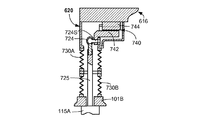
図6及び図7は、バルブアセンブリ600の代替的な実施形態、及びそのカップリング620を示している。バルブアセンブリ600は、以前説明されたように支持部材616に結合される、1つのピースの傾斜角調整可能バルブ114を含む。支持部材616は、支持リング634、及び示されている管状のスペーサなどのスペーサ636を含み得る。他のスペーサの構成が、使用され得る。支持リング634は、流量制限器633を含み得、それは、支持リング634の周りに配置され得、かつ処理ガスが流路616Pを通り抜けて出口103Eへ至る際に、処理ガスの流路の中へ突き出る、又は突出する。流量制限器633は、任意の形状であってよく、かつ流路616Pのうちの1つ又は全部の中の1以上の位置において提供され得る。流量制限器633は、望まれるように、均一な又は不均一なパターンの中において提供され得る。流量制限器633は、流れの不均一を助長し得る流れの異常を付加するように機能し得る。カップリング620は、支持リング634のスポーク638の位置に隣接する、支持リング634に各々取り付けられ得る。
FIGS. 6 and 7 illustrate an alternative embodiment of the
各々のカップリング620は、アクチュエータ115Aのアクチュエータシャフト725に取り付けられたロッドエンド724、及び支持部材616に取り付けられた線形スライド740を伴って、玉継ぎ手及び線形スライドの組み合わせを含み得る。線形スライド740は、底部101Bと支持部材616との間の縮小による、水平方向のスライド動作を可能にする、任意の構成であってよい。特に、T‐スロットは、第1の線形スライド部材742の中において提供され得、かつT‐形状の部材は、第2の線形スライド部材744上に形成され得る。第2の線形スライド部材744は、(図示せぬ)締め具などによって、支持部材616に結合され得る。第1の線形スライド部材742は、ねじ留め、キャプチャードナット(captured nut)、又は同様なものなどによって、ロッドエンド724のシャフト724Sに結合され得る。幾つかの実施形態において、T‐形状の部材は、第1の線形スライド部材742上に提供され得、かつT‐スロットは、第2の線形スライド部材744上に提供され得る。幾つかのフレキシブルなベローズ730A、730Bは、底部101Bと支持部材616との間を密封するために使用され得る。
Each
図8は、電子装置処理システム800内の傾斜角調整可能バルブアセンブリの更に別の代替的な実施形態を示している。この実施形態において、カップリング420は、図4の中において以前に説明したように、傾斜角調整可能バルブと支持部材416Aから416Cとの間に結合される。この実施形態において、各々の支持部材416Aから416Cは、それぞれのアクチュエータ815Aから815Cに個別に取り付けられ得る(支持部材416B及びアクチュエータ815Bは、この図の中において示されていない)。バルブアセンブリは、以前に説明したように、バルブアセンブリの上側表面に取り付けられたカップリング420のうちの各々を有する、1つのピースの傾斜角調整可能バルブ114を含む。支持部材416Aから416Cは、それぞれのカップリング420と、かつアクチュエータ815Aから815Cのそれぞれのシャフト825Aから825Cとの間に結合され得る。
FIG. 8 illustrates yet another alternative embodiment of a tilt angle adjustable valve assembly within the electronic
別の代替的なカップリング920が、図9の中において示されている。この実施形態において、リーフスプリングタイプの屈曲部932は、傾斜角調整可能バルブ114の傾きによる角変形を受け入れるように構成され、かつ適合される。描かれている実施形態の中において、カップリング920は、シャフト925と支持部材916との間に取り付けられ得る。しかしながら、カップリング920はまた、カップリング920が支持部材416AからCと傾斜角調整可能バルブ114との間に結合される、図8におけるように構成され得る。図3の中において示される屈曲部332に対して以前に説明したように、屈曲部932は、スクリュー、ボルト、又は同様なものなどの、締め具によって支持部材916に結合され得る。同様に、屈曲部932は、スクリュー、ボルト、又は同様なものなどの、締め具によってシャフト925に結合され得る。屈曲部932は、例えば、オーバーラッピングリーブ(overlapping leave)932U、932Lを含み得る。屈曲部932は、スチールなどのフレキシブルな材料から製造され得、かつスプリングの様な質を披歴するために、適切な薄さを有し得る。示されているように、フレキシブルなベローズ230が、カップリング920の周りを密封するために含まれ得る。
Another
図10及び図11は、(例えば、電子装置処理システム800などの)電子装置処理システム内での使用のための傾斜角調整可能バルブアセンブリの別の代替的な実施形態を示している。この実施形態において、カップリング1020は、以前に説明したように、傾斜角調整可能バルブ114と、個別の支持部材416Aから416Cとの間に結合され得る。(例えば、アクチュエータ415Aから415Cの)アクチュエータは、それぞれの支持部材416Aから416Cのうちの各々に取り付けられ得る。バルブアセンブリは、以前に説明したように、バルブアセンブリの上側表面に取り付けられたカップリング1020のうちの各々を有する、1つのピースの傾斜角調整可能バルブ114を含む。支持部材416Aから416Cは、それぞれのカップリング1020と、(図10及び図11の中において示されぬ)アクチュエータのそれぞれのシャフトとの間に結合され得る。カップリング1020は、傾斜角調整可能バルブ114の傾きによる角変形及び縮小の両方を受け入れるように構成され、かつ適合されたコイルスプリングタイプの屈曲部1032を含み得る。コイルスプリング屈曲部1032は、溶接又はスプリングリテーナなどによって、エンド部材1055U、1055Lに結合され得る。コンタクト1056は、傾斜角調整可能バルブ114が、バルブシート112に全接触する場合、傾斜角調整可能バルブ114に結合されるコンタクトレシーバ1057との接触によって、傾斜角調整可能バルブ114の近くにしっかりと提供され得る。このやり方において、優れたフレキシビリティー及び傾きの受け入れが提供されるが、実質的な密封力が発達され得る。
10 and 11 illustrate another alternative embodiment of a tilt adjustable valve assembly for use in an electronic device processing system (eg, electronic device processing system 800). In this embodiment, the
図12A及び図2Bは、バルブアセンブリ1200及びバルブアセンブリ1200のカップリング1220の代替的な実施形態を示している。バルブアセンブリ1200は、以前に説明されたように、支持部材1216に結合される、1つのピースの傾斜角調整可能バルブ114を含む。カップリング1220は、各々、各々の支持部材1216と傾斜角調整可能バルブ114との間に取り付けられ得る。
12A and 2B illustrate an alternative embodiment of the
各々のカップリング1220は、支持部材1216に取り付けられるボール1258を有する玉継ぎ手を含み得る。ボール1258は、コネクタ1260によって支持部材1216に結合され得る。コネクタ1260は、幾つかの実施形態において、ボール1258と統合され得、かつコネクタ1260は、例えば、支持部材1216の中へねじ留めされ得る。ボール1258は、傾斜角調整可能バルブ114において形成されるソケット1262の中に受け入れられる。ソケット1262は、傾斜角調整可能バルブ114に結合され、又は統合されるソケット部材1264によって形成され得る。ソケット1262の何らかの部分は、傾斜角調整可能バルブ114によって形成され得る。スプリング1232は、支持部材1216と傾斜角調整可能バルブ114との間に結合され得る。一緒に、ボール1258及びソケット1262が玉継ぎ手に対して提供される。
Each
ボールは、ソケット部材1264の内側の円錐領域と相互作用し得る、上端部分の部分的な円錐領域を含み得る。この構成は、バルブシートと傾斜角調整可能バルブ114との間の縮小及び角変形の両方を受け入れる。傾斜角調整可能バルブ114の正閉包は、傾斜角調整可能バルブ114の中の凹部と接触するように受け入れられる、ボール1258の底部によって達成され得る。例えば、ボール1258の底部の円錐部分は、凹部の中の円錐表面と接触し得る。
The ball may include a partial conical region of the upper end portion that may interact with the conical region inside the
本発明の1以上の実施形態による、(例えば、処理チャンバ102)内の処理ガスの流れを制御する方法1300が、図13を参照しながら提供され、かつ説明される。方法1300は、1302で、(例えば、処理チャンバ102などの)処理チャンバを提供し、かつ1304で、(例えば、バルブシート112などの)バルブシート及び(例えば、傾斜角調整可能バルブ114などの)傾斜角調整可能バルブを含む(例えば、処理ガス出口103Eなどの)処理ガス出口を提供する。1306で、流量パターンが、バルブシートに関して傾斜角調整可能バルブを傾けることによって、処理チャンバの中で調整される。1以上の実施形態の中において、傾斜角調整可能バルブを傾けることは、(例えば、アクチュエータ115Aから115Cなどの)複数のアクチュエータを用いて、傾斜角調整可能バルブを作動させることを含む。別の方法の側面において、傾斜角調整可能バルブの傾きによる縮小は、本明細書の中において説明されるように、1以上のカップリングによって受け入れられ得る。カップリングは、傾斜角調整可能バルブの傾きによる回転変形を受け入れる。1以上の実施形態において、傾斜角調整可能バルブを傾けることは、傾斜角調整可能バルブに結合される1以上の支持部材を作動させることによって提供される。方法の最大の目的は、傾斜角調整可能バルブを傾けることによって、処理チャンバ内のガス流量パターンの不均一を最小化することである。
A
図14から図16は、代替的な傾斜角調整可能バルブアセンブリ1400を含む、処理チャンバガス流制御装置を示している。傾斜角調整可能バルブアセンブリ1400は、複数の支持部材1416Aから1416Bによって支持され得る、(例えば、ソリッドディスクなどの)傾斜角調整可能バルブ1414を含む。支持部材1416Aのような、(図示せぬ)付加的な支持部材は、支持部材1416A及び支持部材1416Bから等しい距離において位置決めされ得る。アクチュエータ1415Aのような、(図示せぬが、3つの等しいアクチュエータが含まれ得る)アクチュエータは、カップリング1420によってそれぞれの支持部材1416A、1416B、及び(図示せぬ)他の支持部材に直接に取り付けられ得る。各々のカップリング1420は、等しい可能性があり、かつ屈曲部1432を含み得、ここで、屈曲部1432は、傾斜角調整可能バルブ1414の傾きによる角変形及び縮小変位の両方を受け入れ得る。
14-16 illustrate a process chamber gas flow control device that includes an alternative tilt angle
傾斜角調整可能バルブアセンブリ1400は、示されるプレート形状のバルブなどの、1つのピースの傾斜角調整可能バルブ1414を含み、それは、(例えば、支持部材1416A、1416B、及び他の)支持部材に結合され得る。支持部材1416A、1416B、及び他のものは、別の部材と統合されるか又は取り付けられることによって、傾斜角調整可能バルブ1414に結合され得る。他の支持部材の構成が使用され得る。支持部材1416A、1416B、及び他のものは、(カップリング1420のような)カップリングが取り付けられ得る、タブ延伸部を備え得る。カップリング1420は、各々、それぞれの支持部材1416A、1416B、及び(図示せぬ)他の部材に取り付けられ得る。
The tilt angle
示される実施形態において、傾斜角調整可能バルブアセンブリ1400は、傾斜角調整可能バルブ1414であって、アクチュエータ1415Aが傾斜角調整可能バルブ1414を傾けるように構成されかつ適合される、傾斜角調整可能バルブ1414、傾斜角調整可能バルブ1414に結合される(例えば、1416Aなどの)支持部材、支持部材1416Aに結合される屈曲部1432、並びにアクチュエータ1415A及び屈曲部1432に結合されるアクチュエータシャフト1425を含む。描かれている実施形態において、屈曲部1432は、例えば、ダブルスタート機械加工されたスプリング部材であり得る。屈曲部1432は、適切な締め具によって、それぞれの支持部材1416A、1416B、及び他のものの中において形成されたポケットの中に固定され得る。他の適切な屈曲部のタイプが、代用され得る。3つの等しいカップリング1420及び(アクチュエータ1415Aのような)アクチュエータは、それぞれの支持部材1416A、1416B、及び他のものに結合され得る。
In the illustrated embodiment, the tilt angle
アクチュエータシャフト1425と、処理チャンバ102を含むハウジング101との間を密封する、ベローズ1430が提供され得る。ベローズ1430は、ねじ締め具、又は同様なものによって、アクチュエータシャフト1425、及びハウジング101に結合され得る。
A bellows 1430 may be provided that seals between the
傾斜角調整可能バルブアセンブリ1400は、傾斜角調整可能バルブ1414を望まれるように傾けるために、(例えば、1415A、及び他のものなどの)アクチュエータに対する信号を介して傾けるために作動可能である。以前の実施形態におけるように、(例えば、1415A、及び他のものなどの)アクチュエータは、処理チャンバを通る平均流量を制御するために、傾斜角調整可能バルブ1414を上げ下げすることと調和して、作動され得る。それらはまた、傾きをもたらすために独立して作動され得る。アクチュエータの上げ下げの組み合わせは、伝達率及び流れの不均一性の両方を制御するために使用され得る。描かれている実施形態において、(例えば、アクチュエータ1415A、及び他のものなどの)アクチュエータのそれぞれの位置の再‐ゼロイングは、傾斜角調整可能バルブ1414をバルブシートに接触するように下げることによって達成され得る。屈曲部1432は、傾斜角調整可能バルブ1414が、傾斜角調整可能バルブ1414の閉鎖に際して密封する改良されたバルブを完成するために、わずかに位置を移動させる(例えば、傾ける)ことを可能にする。
The tilt angle
これまでの説明は、本発明の例示的な実施形態のみを開示する。本発明の範囲内に含まれる上述の装置、システム、及び方法は、当業者にとって容易に理解可能である。従って、本発明がそれ自身の例示的な実施形態との関連において開示されてきた一方で、他の実施形態が、以下の特許請求の範囲によって定義される本発明の範囲に含まれることは、理解されるべきである。
The foregoing description discloses only exemplary embodiments of the invention. The above-described devices, systems, and methods that fall within the scope of the invention will be readily apparent to those skilled in the art. Thus, while the invention has been disclosed in the context of its own exemplary embodiments, other embodiments are within the scope of the invention as defined by the following claims. Should be understood.
Claims (18)
基板を収容するように適合された処理チャンバを提供すること、
前記基板が前記処理チャンバへ提供され、前記処理チャンバから引き出されるように適合された側部の開口部を提供すること、
前記処理チャンバへの処理ガスインレットを提供すること、
バルブシート及び傾斜角調整可能バルブを含む処理ガス出口を提供すること、及び
前記バルブシートに関して前記傾斜角調整可能バルブを傾けることによって、前記処理チャンバ内の流量パターンを調整すること、を含み、
前記傾斜角調整可能バルブを傾けることが、複数のアクチュエータで前記傾斜角調整可能バルブを作動させることを含む、方法。 A method for controlling the flow of process gas in a process chamber, comprising:
Providing a processing chamber adapted to receive a substrate;
Providing a side opening adapted to be provided to the substrate and withdrawn from the processing chamber;
Providing a process gas inlet to the process chamber;
Providing a process gas outlet including a valve seat and the inclination angle adjustable valves, and by inclining the inclination angle adjustable valve with respect to said valve seat, viewed including the, adjusting the flow rate pattern of the processing chamber,
Inclining the tilt angle adjustable valve includes actuating the tilt angle adjustable valve with a plurality of actuators .
前記基板が前記処理チャンバへ提供され、前記処理チャンバから引き出されるように適合された側部の開口部、
前記処理チャンバへの処理ガスインレット、
バルブシートを含む前記処理チャンバからの処理ガス出口、
前記処理チャンバ内のガス流量パターンを制御するために、前記バルブシートに関して傾くように構成されかつ適合された傾斜角調整可能バルブ、及び
前記バルブシートに関して前記傾斜角調整可能バルブを傾けるように作動可能な複数のアクチュエータを備える、処理チャンバガス流制御装置。 A processing chamber adapted to receive a substrate,
Side openings adapted to provide the substrate to the processing chamber and to be withdrawn from the processing chamber;
A process gas inlet to the process chamber;
A process gas outlet from the process chamber including a valve seat ;
A tilt adjustable valve configured and adapted to tilt with respect to the valve seat to control a gas flow pattern in the processing chamber ; and
A processing chamber gas flow control device comprising a plurality of actuators operable to tilt the tilt angle adjustable valve with respect to the valve seat .
前記傾斜角調整可能バルブを傾けるように適合されたアクチュエータ、
前記傾斜角調整可能バルブに結合された支持部材、
前記支持部材に結合された屈曲部、及び
前記アクチュエータ及び前記屈曲部に結合されたアクチュエータロッド
を含む傾斜角調整可能バルブアセンブリを備える、請求項5に記載の処理チャンバガス流制御装置。 The tilt angle adjustable valve,
An actuator adapted to tilt the tilt angle adjustable valve;
A support member coupled to the tilt angle adjustable valve;
6. The process chamber gas flow control device of claim 5 , comprising a bend angle adjustable valve assembly including a bend coupled to the support member, and an actuator rod coupled to the actuator and the bend.
前記複数の支持部材のうちの各々に結合されたアクチュエータを備える、請求項5に記載の処理チャンバガス流制御装置。 6. The process chamber gas flow control device of claim 5 , comprising: a plurality of support members coupled to the tilt angle adjustable valve; and an actuator coupled to each of the plurality of support members.
前記傾斜角調整可能バルブに結合され、かつ傾きによる角度ズレ及び縮小変位を受け入れるように適合された、玉継ぎ手及び線形スライドの組み合わせ、を備え、
前記縮小変位は、前記傾斜角調整可能バルブが傾くことにより生じる変位である、請求項5に記載の処理チャンバガス流制御装置。 A plurality of actuators operable to tilt the tilt angle adjustable valve; and a ball joint and linear slide coupled to the tilt angle adjustable valve and adapted to accept angular misalignment and reduced displacement due to tilt. combination, with a,
The processing chamber gas flow control device according to claim 5 , wherein the reduction displacement is a displacement generated when the tilt angle adjustable valve is tilted .
ハウジングの底部と支持部材との間を密封する、
1以上のベローズを備える、請求項5に記載の処理チャンバガス流制御装置。 Sealing between the support member and the tilt angle adjustable valve, or
Sealing between the bottom of the housing and the support member;
6. The process chamber gas flow control device of claim 5 , comprising one or more bellows.
前記基板が前記処理チャンバへ提供され、前記処理チャンバから引き出されるように適合された側部の開口部、
前記処理チャンバへの処理ガスインレット、
バルブシート及び傾斜角調整可能バルブを含む前記処理チャンバからの処理ガス出口であって、前記傾斜角調整可能バルブは、前記処理チャンバ内のガス流量パターンを調整するために、前記バルブシートに関して傾くように構成されかつ適合されている、処理ガス出口、及び
前記バルブシートに関して前記傾斜角調整可能バルブを傾けるように作動可能な複数のアクチュエータを備える、電子装置処理システム。 A processing chamber adapted to receive a substrate ,
Side openings adapted to provide the substrate to the processing chamber and to be withdrawn from the processing chamber;
A process gas inlet to the process chamber ;
A process gas outlet from the process chamber including a valve seat and a tilt angle adjustable valve, wherein the tilt angle adjustable valve is tilted with respect to the valve seat to adjust a gas flow pattern in the process chamber; A process gas outlet configured and adapted to , and
An electronic device processing system comprising a plurality of actuators operable to tilt the tilt angle adjustable valve with respect to the valve seat .
Applications Claiming Priority (3)
| Application Number | Priority Date | Filing Date | Title |
|---|---|---|---|
| US201261732186P | 2012-11-30 | 2012-11-30 | |
| US61/732,186 | 2012-11-30 | ||
| PCT/US2013/072079 WO2014085497A1 (en) | 2012-11-30 | 2013-11-26 | Process chamber gas flow apparatus, systems, and methods |
Publications (3)
| Publication Number | Publication Date |
|---|---|
| JP2016505711A JP2016505711A (en) | 2016-02-25 |
| JP2016505711A5 JP2016505711A5 (en) | 2017-01-19 |
| JP6180541B2 true JP6180541B2 (en) | 2017-08-16 |
Family
ID=50824243
Family Applications (1)
| Application Number | Title | Priority Date | Filing Date |
|---|---|---|---|
| JP2015545199A Active JP6180541B2 (en) | 2012-11-30 | 2013-11-26 | Process chamber gas flow apparatus, system, and method |
Country Status (6)
| Country | Link |
|---|---|
| US (1) | US9429248B2 (en) |
| JP (1) | JP6180541B2 (en) |
| KR (1) | KR101800719B1 (en) |
| CN (1) | CN104812939B (en) |
| TW (1) | TWI587358B (en) |
| WO (1) | WO2014085497A1 (en) |
Families Citing this family (10)
| Publication number | Priority date | Publication date | Assignee | Title |
|---|---|---|---|---|
| TWM539571U (en) * | 2015-07-27 | 2017-04-11 | 應用材料股份有限公司 | Substrate lift pin actuator |
| EP3258149A1 (en) * | 2016-06-14 | 2017-12-20 | VAT Holding AG | Vacuum valve for flow control and for interrupting a flow path |
| EP3406340B1 (en) * | 2017-05-26 | 2021-07-07 | Thinxxs Microtechnology Ag | Flow cell with housing component |
| WO2020033378A1 (en) * | 2018-08-07 | 2020-02-13 | Persimmon Technologies Corp. | Direct-drive flexure-mechanism vacuum control valve |
| FI130051B (en) * | 2019-04-25 | 2023-01-13 | Beneq Oy | Apparatus and method |
| GB2584160A (en) * | 2019-05-24 | 2020-11-25 | Edwards Ltd | Vacuum assembly and vacuum pump with an axial through passage |
| WO2021181498A1 (en) * | 2020-03-10 | 2021-09-16 | 株式会社Kokusai Electric | Substrate treatment device, exhaust flow rate control device, and method for manufacturing semiconductor device |
| TW202200817A (en) | 2020-06-17 | 2022-01-01 | 美商應用材料股份有限公司 | High temperature chemical vapor deposition lid |
| RU2747895C1 (en) * | 2020-10-19 | 2021-05-17 | Юрий Иванович Духанин | Cryogenic shut-off and control valve |
| US20230095095A1 (en) * | 2021-09-27 | 2023-03-30 | Applied Materials, Inc. | Method of isolating the chamber volume to process volume with internal wafer transfer capability |
Family Cites Families (32)
| Publication number | Priority date | Publication date | Assignee | Title |
|---|---|---|---|---|
| AT356989B (en) * | 1975-03-11 | 1980-06-10 | Wurzer Lothar | DEVICE FOR SEPARATING TWO NEIGHBORING SPACES OF THE SAME OR DIFFERENT PRESSURE BY MEANS OF A MEMBRANE |
| DE2940239A1 (en) * | 1979-10-04 | 1981-04-16 | Robert Bosch Gmbh, 7000 Stuttgart | ELECTROMAGNETICALLY ACTUABLE VALVE |
| DE4119955C2 (en) * | 1991-06-18 | 2000-05-31 | Danfoss As | Miniature actuator |
| JP2729916B2 (en) * | 1994-04-28 | 1998-03-18 | 大明金属工業株式会社 | Flat plug |
| JPH09260230A (en) * | 1996-03-22 | 1997-10-03 | Toshiba Corp | Semiconductor device manufacturing device and manufacture thereof |
| US5954079A (en) | 1996-04-30 | 1999-09-21 | Hewlett-Packard Co. | Asymmetrical thermal actuation in a microactuator |
| US5667197A (en) * | 1996-07-09 | 1997-09-16 | Lam Research Corporation | Vacuum chamber gate valve and method for making same |
| US6079693A (en) * | 1998-05-20 | 2000-06-27 | Applied Komatsu Technology, Inc. | Isolation valves |
| US6192827B1 (en) * | 1998-07-03 | 2001-02-27 | Applied Materials, Inc. | Double slit-valve doors for plasma processing |
| JP2001239143A (en) * | 2000-02-29 | 2001-09-04 | Showa Shinku:Kk | Vacuum apparatus equipped with antisticking baffle with exhaust gas speed adjusting function |
| US6592709B1 (en) | 2000-04-05 | 2003-07-15 | Applied Materials Inc. | Method and apparatus for plasma processing |
| JP3756429B2 (en) | 2001-07-12 | 2006-03-15 | Smc株式会社 | Flow control valve |
| US20030168174A1 (en) | 2002-03-08 | 2003-09-11 | Foree Michael Todd | Gas cushion susceptor system |
| CN1184669C (en) * | 2002-12-10 | 2005-01-12 | 西安电子科技大学 | SiGe/Si chemical vapor deposition growth process |
| US7497414B2 (en) * | 2004-06-14 | 2009-03-03 | Applied Materials, Inc. | Curved slit valve door with flexible coupling |
| JP2006292130A (en) * | 2005-04-14 | 2006-10-26 | Matsushita Electric Ind Co Ltd | Gate valve |
| JP4491737B2 (en) * | 2005-05-27 | 2010-06-30 | Smc株式会社 | Vacuum valve |
| US7845618B2 (en) * | 2006-06-28 | 2010-12-07 | Applied Materials, Inc. | Valve door with ball coupling |
| JP4299863B2 (en) * | 2007-01-22 | 2009-07-22 | エルピーダメモリ株式会社 | Manufacturing method of semiconductor device |
| US8377213B2 (en) | 2008-05-05 | 2013-02-19 | Applied Materials, Inc. | Slit valve having increased flow uniformity |
| JP2010034505A (en) * | 2008-06-30 | 2010-02-12 | Canon Anelva Corp | Stacked load lock chamber, and substrate processing apparatus including the same |
| KR101522251B1 (en) | 2008-09-22 | 2015-05-21 | 어플라이드 머티어리얼스, 인코포레이티드 | Etch reactor suitable for etching high aspect ratio features |
| JP4265815B1 (en) * | 2008-10-27 | 2009-05-20 | 株式会社シンクロン | Deposition equipment |
| EP2315236B1 (en) * | 2009-10-22 | 2014-05-14 | VAT Holding AG | Flap transfer valve |
| EP2336611A1 (en) * | 2009-12-15 | 2011-06-22 | Applied Materials, Inc. | Water cooled valve |
| EP2355132B1 (en) * | 2010-02-04 | 2014-05-21 | VAT Holding AG | Flap transfer valve with pivoting valve closure boards |
| US8562742B2 (en) * | 2010-04-30 | 2013-10-22 | Applied Materials, Inc. | Apparatus for radial delivery of gas to a chamber and methods of use thereof |
| US8652297B2 (en) | 2010-08-03 | 2014-02-18 | Applied Materials, Inc. | Symmetric VHF plasma power coupler with active uniformity steering |
| JP5683388B2 (en) | 2010-08-19 | 2015-03-11 | 株式会社日立国際電気 | Semiconductor device manufacturing method, substrate processing method, and substrate processing apparatus |
| US9091371B2 (en) * | 2010-12-27 | 2015-07-28 | Kenneth K L Lee | Single axis gate valve for vacuum applications |
| US8801950B2 (en) * | 2011-03-07 | 2014-08-12 | Novellus Systems, Inc. | Reduction of a process volume of a processing chamber using a nested dynamic inert volume |
| CN103014661A (en) * | 2011-09-20 | 2013-04-03 | 吉富新能源科技(上海)有限公司 | Showerhead air flow design for plating uniform silicon film |
-
2013
- 2013-11-26 WO PCT/US2013/072079 patent/WO2014085497A1/en active Application Filing
- 2013-11-26 US US14/091,130 patent/US9429248B2/en active Active
- 2013-11-26 KR KR1020157016707A patent/KR101800719B1/en active IP Right Grant
- 2013-11-26 CN CN201380061955.1A patent/CN104812939B/en active Active
- 2013-11-26 JP JP2015545199A patent/JP6180541B2/en active Active
- 2013-11-29 TW TW102143863A patent/TWI587358B/en active
Also Published As
| Publication number | Publication date |
|---|---|
| KR101800719B1 (en) | 2017-11-23 |
| TWI587358B (en) | 2017-06-11 |
| JP2016505711A (en) | 2016-02-25 |
| TW201432782A (en) | 2014-08-16 |
| KR20150089047A (en) | 2015-08-04 |
| CN104812939A (en) | 2015-07-29 |
| US20140150878A1 (en) | 2014-06-05 |
| WO2014085497A1 (en) | 2014-06-05 |
| US9429248B2 (en) | 2016-08-30 |
| CN104812939B (en) | 2017-02-22 |
Similar Documents
| Publication | Publication Date | Title |
|---|---|---|
| JP6180541B2 (en) | Process chamber gas flow apparatus, system, and method | |
| JP6802191B2 (en) | Positioning and rotating device of susceptor, and method of use | |
| US9728380B2 (en) | Dual-plenum showerhead with interleaved plenum sub-volumes | |
| JP2016505711A5 (en) | ||
| KR101671158B1 (en) | Cvd apparatus for improved film thickness non-uniformity and particle performance | |
| TW202004954A (en) | Precision dynamic leveling mechanism with long motion capability | |
| JP6513089B2 (en) | Processing chamber apparatus, system and method for controlling gas flow patterns | |
| KR101892339B1 (en) | Substrate processing apparatus | |
| US20080017116A1 (en) | Substrate support with adjustable lift and rotation mount | |
| CN105719989A (en) | Reducing Backside Deposition At Wafer Edge | |
| US20140026816A1 (en) | Multi-zone quartz gas distribution apparatus | |
| US20080017117A1 (en) | Substrate support with adjustable lift and rotation mount | |
| KR20170080501A (en) | Actuator to dynamically adjust showerhead tilt in a semiconductor processing apparatus | |
| US11742235B2 (en) | Coaxial lift device with dynamic leveling | |
| US20170175265A1 (en) | Flat susceptor with grooves for minimizing temperature profile across a substrate | |
| KR20200040868A (en) | Valve device | |
| JP2023008923A (en) | Vacuum processing system comprising process chamber with vacuum control valve |
Legal Events
| Date | Code | Title | Description |
|---|---|---|---|
| A521 | Request for written amendment filed |
Free format text: JAPANESE INTERMEDIATE CODE: A523 Effective date: 20161124 |
|
| A621 | Written request for application examination |
Free format text: JAPANESE INTERMEDIATE CODE: A621 Effective date: 20161124 |
|
| A871 | Explanation of circumstances concerning accelerated examination |
Free format text: JAPANESE INTERMEDIATE CODE: A871 Effective date: 20161124 |
|
| A975 | Report on accelerated examination |
Free format text: JAPANESE INTERMEDIATE CODE: A971005 Effective date: 20170206 |
|
| A131 | Notification of reasons for refusal |
Free format text: JAPANESE INTERMEDIATE CODE: A131 Effective date: 20170221 |
|
| A521 | Request for written amendment filed |
Free format text: JAPANESE INTERMEDIATE CODE: A523 Effective date: 20170519 |
|
| TRDD | Decision of grant or rejection written | ||
| A01 | Written decision to grant a patent or to grant a registration (utility model) |
Free format text: JAPANESE INTERMEDIATE CODE: A01 Effective date: 20170627 |
|
| A61 | First payment of annual fees (during grant procedure) |
Free format text: JAPANESE INTERMEDIATE CODE: A61 Effective date: 20170718 |
|
| R150 | Certificate of patent or registration of utility model |
Ref document number: 6180541 Country of ref document: JP Free format text: JAPANESE INTERMEDIATE CODE: R150 |
|
| R250 | Receipt of annual fees |
Free format text: JAPANESE INTERMEDIATE CODE: R250 |
|
| R250 | Receipt of annual fees |
Free format text: JAPANESE INTERMEDIATE CODE: R250 |
|
| R250 | Receipt of annual fees |
Free format text: JAPANESE INTERMEDIATE CODE: R250 |
|
| R250 | Receipt of annual fees |
Free format text: JAPANESE INTERMEDIATE CODE: R250 |