JP6176984B2 - Power transmission device, power transmission device control method, and program - Google Patents
Power transmission device, power transmission device control method, and program Download PDFInfo
- Publication number
- JP6176984B2 JP6176984B2 JP2013084240A JP2013084240A JP6176984B2 JP 6176984 B2 JP6176984 B2 JP 6176984B2 JP 2013084240 A JP2013084240 A JP 2013084240A JP 2013084240 A JP2013084240 A JP 2013084240A JP 6176984 B2 JP6176984 B2 JP 6176984B2
- Authority
- JP
- Japan
- Prior art keywords
- power
- power transmission
- power receiving
- cpu
- receiving device
- Prior art date
- Legal status (The legal status is an assumption and is not a legal conclusion. Google has not performed a legal analysis and makes no representation as to the accuracy of the status listed.)
- Expired - Fee Related
Links
- 230000005540 biological transmission Effects 0.000 title claims description 287
- 238000000034 method Methods 0.000 title claims description 93
- 230000008569 process Effects 0.000 description 79
- 238000004891 communication Methods 0.000 description 53
- 238000012545 processing Methods 0.000 description 42
- 238000010586 diagram Methods 0.000 description 18
- 230000006870 function Effects 0.000 description 12
- 230000000694 effects Effects 0.000 description 7
- 230000004044 response Effects 0.000 description 7
- 238000005259 measurement Methods 0.000 description 6
- 238000011156 evaluation Methods 0.000 description 4
- 238000009774 resonance method Methods 0.000 description 4
- 230000006641 stabilisation Effects 0.000 description 4
- 238000011105 stabilization Methods 0.000 description 4
- 238000012546 transfer Methods 0.000 description 4
- 230000003247 decreasing effect Effects 0.000 description 3
- 238000012854 evaluation process Methods 0.000 description 3
- 239000004973 liquid crystal related substance Substances 0.000 description 3
- 238000002360 preparation method Methods 0.000 description 3
- 230000008859 change Effects 0.000 description 1
- 238000012790 confirmation Methods 0.000 description 1
- 238000010168 coupling process Methods 0.000 description 1
- 230000005684 electric field Effects 0.000 description 1
- 230000005674 electromagnetic induction Effects 0.000 description 1
- 238000012986 modification Methods 0.000 description 1
- 230000004048 modification Effects 0.000 description 1
- 238000003825 pressing Methods 0.000 description 1
- 230000009467 reduction Effects 0.000 description 1
Images


Classifications
-
- H—ELECTRICITY
- H02—GENERATION; CONVERSION OR DISTRIBUTION OF ELECTRIC POWER
- H02J—CIRCUIT ARRANGEMENTS OR SYSTEMS FOR SUPPLYING OR DISTRIBUTING ELECTRIC POWER; SYSTEMS FOR STORING ELECTRIC ENERGY
- H02J50/00—Circuit arrangements or systems for wireless supply or distribution of electric power
- H02J50/10—Circuit arrangements or systems for wireless supply or distribution of electric power using inductive coupling
-
- H—ELECTRICITY
- H01—ELECTRIC ELEMENTS
- H01F—MAGNETS; INDUCTANCES; TRANSFORMERS; SELECTION OF MATERIALS FOR THEIR MAGNETIC PROPERTIES
- H01F38/00—Adaptations of transformers or inductances for specific applications or functions
- H01F38/14—Inductive couplings
-
- H—ELECTRICITY
- H02—GENERATION; CONVERSION OR DISTRIBUTION OF ELECTRIC POWER
- H02J—CIRCUIT ARRANGEMENTS OR SYSTEMS FOR SUPPLYING OR DISTRIBUTING ELECTRIC POWER; SYSTEMS FOR STORING ELECTRIC ENERGY
- H02J50/00—Circuit arrangements or systems for wireless supply or distribution of electric power
- H02J50/80—Circuit arrangements or systems for wireless supply or distribution of electric power involving the exchange of data, concerning supply or distribution of electric power, between transmitting devices and receiving devices
Description
本発明は、送電装置、送電方法及びプログラムに関する。 The present invention relates to a power transmission device, a power transmission method, and a program.
従来、非接触(無線)で電力の供給を行う技術が知られている。非接触による電力供給の方式としては、以下に示す4つの方式がある。すなわち、電磁誘導方式、磁界共鳴方式、電界結合方式及び電波受信方式である。このうち、磁界共鳴方式は、送電できる十分な電力と長い送電距離が特徴として挙げられ、そのため磁界共鳴方式は、4つの方式の中で特に注目されている。磁界共鳴方式においては、この送電距離を活かして、送電装置が複数の受信装置へ無線により送電を行う1対Nの給電方式が提案されている(例えば、特許文献1参照)。 2. Description of the Related Art Conventionally, a technique for supplying power in a contactless (wireless) manner is known. There are the following four methods for non-contact power supply. That is, an electromagnetic induction method, a magnetic field resonance method, an electric field coupling method, and a radio wave reception method. Among these, the magnetic field resonance method is characterized by sufficient electric power that can be transmitted and a long transmission distance, and therefore, the magnetic field resonance method is particularly attracting attention among the four methods. In the magnetic field resonance method, a 1-to-N power feeding method in which the power transmission device wirelessly transmits power to a plurality of receiving devices by utilizing this power transmission distance has been proposed (see, for example, Patent Document 1).
特許文献1の技術では、送電装置は、送電を行っていないスタンバイモード時に一定のパルス信号を発信して数メートル以内に受電装置が近接しているか探索する。そして、受信装置が自身の固有IDを送電装置へ送ると、送電装置は、固有IDの送信元が給電対象の受電装置であるか否かを判別する。給電対象の受電装置である場合、送電装置は、受電装置へ電力を供給する。このとき、送電装置は、充電量や機器の状態などを個別に受信するために、受電装置へ固有のコードを送ることができる。
In the technique of
送電装置による送電可能な送電エリアは限られている。したがって、携帯型の受電装置の場合には、受電装置への送電を行う際に、ユーザは、送電エリア内に受電装置を移動させる必要がある。また、送電エリア内であっても、送電装置と受電装置との間に障害物が存在し、送電装置に電力が到達しない場合もある。
しかしながら、どの位置まで移動させれば受電装置への電力の伝送効率を高められるかをユーザが把握するのは難しい。このため、伝送効率の悪い状態で電力伝送が行われる場合があった。これにより、無駄な電力が消費されてしまうという問題があった。
The power transmission area where power can be transmitted by the power transmission device is limited. Therefore, in the case of a portable power receiving device, when power is transmitted to the power receiving device, the user needs to move the power receiving device into the power transmission area. Even in the power transmission area, there may be an obstacle between the power transmission device and the power reception device, and power may not reach the power transmission device.
However, it is difficult for the user to grasp to which position the transmission efficiency of power to the power receiving device can be increased. For this reason, power transmission may be performed in a state where transmission efficiency is poor. As a result, there is a problem that wasteful power is consumed.
本発明はこのような問題点に鑑みなされたもので、無駄な電力消費を低減することを目的とする。 The present invention has been made in view of such problems, and an object thereof is to reduce wasteful power consumption.
そこで、本発明は、送電装置であって、受電装置に対して無線で電力を供給する無線給電手段と、前記無線給電手段によって電力を供給中の受電装置から受電電力量を取得する取得手段と、受電装置の識別情報と、過去に前記取得手段が当該受電装置から取得した受電電力量の最大値とを対応付けて記憶する記憶手段と、前記取得手段が取得した前記受電電力量が、前記電力を供給中の受電装置に対応する前記最大値から算出される値である基準値より少ないか否かを判定する判定手段と、前記受電電力量が前記基準値より少ないと前記判定手段によって判定された場合に、前記電力を供給中の受電装置を前記送電装置に近付けるようにユーザに促す通知手段とを備え、前記判定手段において使用される基準値は、複数の受電装置それぞれに対して個別に設定される値であることを特徴とする。 Therefore, the present invention is a power transmission device, a wireless power supply unit that wirelessly supplies power to the power reception device, and an acquisition unit that acquires the received power amount from the power reception device that is supplying power by the wireless power supply unit. A storage unit that associates and stores the identification information of the power receiving device and the maximum value of the received power amount acquired by the acquiring unit from the power receiving device in the past, and the received power amount acquired by the acquiring unit includes: determining a determination unit configured to determine whether less than the reference value is a value calculated from the maximum value corresponding to the power receiving device in the feed power, and the received power amount is smaller than the reference value by said judging means And a notification unit that prompts the user to bring the power receiving device that is supplying the power close to the power transmitting device, and the reference value used in the determination unit is set to each of the plurality of power receiving devices. Characterized in that it is a value that is individually configured.
本発明によれば、無駄な電力消費を低減することができる。 According to the present invention, useless power consumption can be reduced.
以下、本発明の実施形態について図面に基づいて説明する。
図1は、電力伝送システムを示す図である。電力伝送システムは、送電装置10と、複数の受電装置20とを備えている。送電装置10は、無線により受電装置20に電力を供給する。また、送電装置10は、受電装置20との間で給電のために必要なデータ通信を行う。受電装置20は、無線により送電装置10から電力の供給を受ける。また、受電装置20は、送電装置10との間で給電のために必要なデータ通信を行う。
図1に示す給電エリア30は、送電装置10から受電装置20へ給電が実行可能なエリアである。給電エリア30は、送電装置10の送電能力により定まる範囲である。通信エリア40は、送電装置10と受電装置20の間においてデータ通信が実行可能なエリアである。
Hereinafter, embodiments of the present invention will be described with reference to the drawings.
FIG. 1 is a diagram illustrating a power transmission system. The power transmission system includes a
A
給電エリア30と通信エリア40の関係について説明する。給電エリア30は、通信エリア40に比べて広いエリアである。具体的には、給電エリア30は、通信エリア40に包含されている。図1に示すように、給電エリア30の中に複数の受電装置20が存在する場合、送電装置10はこれら複数の受電装置20に対して並行して無線給電を実行することが可能である。
The relationship between the
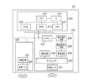
図2は、送電装置を示す図である。なお、図2において、データのやり取りを示す線は実線で示し、電力の供給を示す線は点線で示している。送電装置10は、制御部110、無線送信部120、無線受信部130、AC電源140、及び電源供給部150を含む。
制御部110は、送電装置10を制御する。制御部110は、CPU111、ROM112、RAM113、HDD114及びUI115を含む。制御部110は、無線送信部120及び無線受信部130と内部バスで接続されている。
CPU111は、様々なデータを処理し、送電装置10を制御する。ROM112は、不揮発性の記憶媒体であり、CPU111が使用するブートプログラム等を記憶する。RAM113は、揮発性の記憶媒体であり、CPU111が使用するデータやプログラム等を一時的に記憶する。HDD114は、不揮発性の記憶媒体であり、CPU111が使用するOSやアプリケーション等を記憶する。UI115は、ユーザからの操作入力を受け付ける操作入力部である。UI115はさらに、各種情報を表示する表示部である。UI115は例えば、液晶表示部とタッチパネルとを有している。そして、タッチパネルの押下がCPU111により検出される。
FIG. 2 is a diagram illustrating the power transmission device. In FIG. 2, a line indicating data exchange is indicated by a solid line, and a line indicating power supply is indicated by a dotted line. The
The
The
無線送信部120は、電力を受電装置20へ無線で送信する。無線送信部120は、通信回路121、送電回路122、ダイプレクサー123及び送電コイル124を含む。通信回路121は、通信を行うための変調信号を生成する。送電回路122は、電力を送信するための変調信号を生成する。
ダイプレクサー123は、通信回路121が生成した変調信号と送電回路122が生成した変調信号とを合成する。送電コイル124は、ダイプレクサー123が合成した変調信号を受電装置20へ送信する。
The
The
無線受信部130は、受電装置20からデータを受信する。無線受信部130は、受電コイル131及び復調回路132を含む。受電コイル131は、通信を行うための変調信号を受電装置20から受信する。復調回路132は、受電コイル131が受信した変調信号を復調する。
AC電源140は、交流電圧を送電コイル124と電源供給部150に供給する。電源供給部150は、AC電源140が供給する交流電圧を直流電圧へ変換し、直流電圧を制御部110、無線送信部120及び無線受信部130に供給する。
なお、後述する送電装置10の機能や処理は、CPU111がROM112又はHDD114に格納されているプログラムを読み出し、このプログラムを実行することにより実現されるものである。
The
The
Note that the functions and processing of the
図3は、受電装置20を示す図である。図3において、データのやり取りを示す線は実線で示し、電力の供給を示す線は点線で示している。受電装置20は、制御部210、無線送信部220及び無線受信部230を含む。制御部210は、受電装置20を制御する。制御部210は、CPU211、ROM212、RAM213、HDD214及びUI215を含む。制御部210は、無線送信部220及び無線受信部230と内部バスで接続される。
CPU211は、様々なデータを処理して、受電装置20を制御する。ROM212は、不揮発性の記憶媒体であり、CPU211が使用するブートプログラム等を記憶する。RAM213は、揮発性の記憶媒体であり、CPU211が使用するデータやプログラム等を一時的に記憶する。HDD214は、不揮発性の記憶媒体であり、CPU211が使用するOSやアプリケーション等を記憶する。UI215は、ユーザに様々な情報を表示し、ユーザから様々な指示を受け付ける。
FIG. 3 is a diagram illustrating the
The
無線送信部220は、送電装置10へデータを送信する。無線送信部220は、通信回路221及び送電コイル222を含む。通信回路221は、通信を行うための変調信号を生成する。送電コイル222は、通信回路221が生成した変調信号を送電装置10へ送信する。
無線受信部230は、電力を送電装置10から無線で受信する。無線受信部230は、受電コイル231、ダイプレクサー232、復調回路233、整流回路234、電圧安定化回路235、電力測定回路236及びバッテリー237を含む。受電コイル231は、送電装置10から変調信号を受信する。ダイプレクサー232は、受電コイル231が受信した変調信号を、通信を行うための変調信号と電力を送信するための変調信号に分ける。
The
The
復調回路233は、ダイプレクサー232が分けた通信を行うための変調信号を復調する。整流回路234は、ダイプレクサー232が分けた電力を送信するための変調信号を整流して直流電圧を生成する。電圧安定化回路235は、整流回路234が生成した直流電圧を安定化する。電力測定回路236は、電圧安定化回路235が生成した、安定化した直流電源の電力を測定する。バッテリー237は、電圧安定化回路235が安定化した電圧を受けて、電力を蓄積する。また、バッテリー237は、蓄積した電力を基に、直流電圧を制御部210、無線送信部220及び無線受信部230に供給する。
なお、後述する受電装置20の機能や処理は、CPU211がROM212又はHDD214に格納されているプログラムを読み出し、このプログラムを実行することにより実現されるものである。
The demodulation circuit 233 demodulates the modulation signal for performing communication divided by the
Note that functions and processing of the
図4は、スーパーフレームの一例を示す図である。本実施形態にかかる電力伝送システムは、このようなスーパーフレームを繰り返すことにより、電力伝送処理を行う。1つのスーパーフレームは、S101(関連付け期間)、S102(電力伝送準備期間)、及びS103(電力伝送期間)を有している。なお、それぞれの期間は可変である。
S101において、送電装置10は、受電装置20に対し、IDと電力の必要性の確認を行う。送電装置10が受電装置20からデバイスIDと電力を必要とする旨を受信すると、S102へ移行する。なお、S101からS102へ移行する期間も可変である。
FIG. 4 is a diagram illustrating an example of a superframe. The power transmission system according to the present embodiment performs power transmission processing by repeating such a superframe. One superframe has S101 (association period), S102 (power transmission preparation period), and S103 (power transmission period). Each period is variable.
In S <b> 101, the
S102において、送電装置10は、受電装置20へデータリクエストを送信することができる。送電装置10は、データリクエストの中で送電装置10のデバイスIDを要求することができる。また、受電装置20は、送電装置10からのデータリクエストに対する応答としてアクノリッジを送信することができる。デバイスIDの要求に対しては、受電装置20は、デバイスIDを含むアクノリッジを送信する。なお、それぞれのレスポンスフレームの長さやアクノリッジフレームの長さは可変である。S102が終了すると、S103へ移行する。なお、S102からS103へ移行する期間も可変である。
S103において、送電装置10は、受電装置20へ電力を伝送する。S103において、受電装置20は、送電装置10からのリクエストフレームがなくても、フレームを送電装置10へ送信することができる。
In S <b> 102, the
In S <b> 103, the
図5は、フレームフォーマットの一例を示す図である。前述したスーパーフレームにおいては、図5に示すようなフレームフォーマットのパケットを用いたデータ通信が実現される。このデータ通信により、無線給電を開始するために必要なデータの送受信が行われる。
フレームヘッダー310は、データ転送時の宛先等を示すものである。フレームヘッダー310は、ID311、フレームコントロール312、発信元アドレス313、行先アドレス314及びシーケンスナンバー315を含む。ID311は、電力伝送システムでデータ通信を行うときに使われるIDである。
FIG. 5 is a diagram illustrating an example of a frame format. In the above-described superframe, data communication using a packet having a frame format as shown in FIG. 5 is realized. By this data communication, transmission and reception of data necessary for starting wireless power feeding is performed.
The
フレームコントロール312は、受電装置20のデータ交換のための情報である。フレームコントロール312は、電力管理3120を含む。電力管理3120は、電力の必要性を確認するデータである。発信元アドレス313は、データ転送時における発信元のアドレスである。行先アドレス314は、データ転送時における行先のアドレスである。シーケンスナンバー315は、フレームの番号である。
フレームボディ320は、データ転送時のデータ本体の情報である。フレームボディ320は、ペイロード321及びフレームチェックシーケンス322を含む。ペイロード321は、データ本体である。ペイロード321には、例えば、デバイスID3210や受電電力量3211が割り当てられる。デバイスID3210は、受電装置20の識別情報である。受電電力量3211は、受電装置20が送電装置10から受電した電力量を示す情報である。フレームチェックシーケンス322は、ペイロード321のエラーチェックを行うデータである。
The
The
図6は、スーパーフレームにおける送電装置10と受電装置20との間の電力伝送処理を示すシーケンス図である。前述のスーパーフレームにおいて、以下に示す処理を行うことにより、無線電力伝送のためのデータ通信が実現される。
S201において、送電装置10は、受電装置20に対してIDを要求する。このとき、送電装置10は、フレームフォーマットのID311を用いる。
次に、S202において、送電装置10は、受電装置20からIDを受信する。このとき、送電装置10は、フレームフォーマットのID311を用いる。次に、S203において、送電装置10は、受電装置20に電力の必要性を確認する。このとき、送電装置10は、フレームフォーマットの電力管理3120を用いる。次に、S204において、受電装置20は、受電装置20に電力の必要があれば、送電装置10へ電力必要の通知を行う。このとき、受電装置20は、フレームフォーマットの電力管理3120を用いる。
FIG. 6 is a sequence diagram illustrating a power transmission process between the
In step S <b> 201, the
Next, in S <b> 202, the
また、S204において、受電装置20は、電力が不要であれば、送電装置10へ電力不要の通知を行う。このとき、受電装置20は、フレームフォーマットの電力管理3120を用いる。そして、送電装置10は、受電の必要性の応答結果に基づいて、送電対象の受電装置20を決定する。次に、S205において、送電装置10は、受電装置20に対してデータリクエストとしてデバイスIDを要求する。このとき、送電装置10は、フレームフォーマットのデバイスID3210を用いる。
次に、S206において、受電装置20は、送電装置10に対してレスポンスフレームとしてデバイスIDを送信する。このとき、受電装置20は、フレームフォーマットのデバイスID3210を用いる。
In S <b> 204, if no power is required, the
Next, in S <b> 206, the
次に、S207において、送電装置10は、受電装置20に電力伝送を行う。次に、S208において、送電装置10は、受電装置20に対してデータリクエストとして受電電力量を要求する。このとき、送電装置10は、フレームフォーマットの受電電力量3211を用いる。次に、S209において、受電装置20は、送電装置10に対してレスポンスフレームとして受電電力量を送信する。このとき、受電装置20は、フレームフォーマットの受電電力量3211を用いる。
次に、S210において、受電装置20は、バッテリー237がフルになると、送電装置10へ電力伝送終了の通知を行う。このとき、受電装置20は、フレームフォーマットの電力管理3120を用いる。以上で、1つのスーパーフレームが終了する。このように、スーパーフレーム内において、データ送受信処理を行うことにより、無線電力伝送のためのデータ通信が実現される。
Next, in S <b> 207, the
Next, in S <b> 210, when the
図7は、送電装置10により管理される管理テーブルの一例を示す図である。図7に示す管理テーブル700は、HDD114内に作成され、CPU111により管理される。なお、他の例としては、管理テーブル700は、フラッシュメモリ等の不揮発性のメモリデバイスに格納されることとしてもよい。
管理テーブル700は、過去の送電装置10による電力伝送の履歴情報を記録する。具体的には、管理テーブル700は、デバイスID701と、カレント値702と、最大値703とを対応付けて記録する。デバイスID701は、受電装置20のデバイスIDである。デバイスID701には、スーパーフレームのペイロード321に割り当てられているデバイスID3210が格納される。
カレント値702は、送電装置10が電力伝送を実施中の受電装置20の受電電力量である。カレント値702には、スーパーフレームのペイロード321に割り当てられている受電電力量3211が格納される。最大値703は、各受電装置20から過去に得られた受電電力量の最大値である。すなわち、最大値703は、過去のカレント値の最大値である。ここで、最大値703は、送電装置10が電力の伝送効率を評価する際に参照する値であり、基準値の一例である。
FIG. 7 is a diagram illustrating an example of a management table managed by the
The management table 700 records past power transmission history information by the
The
図8は、送電装置10による電力伝送処理を示すフローチャートである。まず、S801において、送電装置10のCPU111は、無線送信部120を介して、受電装置20にIDを要求する。次に、S802において、CPU111は、無線受信部130を介して、受電装置20からIDを受け取ると(S802でYes)、処理をS803へ進める。S803において、CPU111は、無線送信部120を介して、受電装置20に電力の必要性を確認する。
次に、S804において、CPU111は、無線受信部130を介して、受電装置20から電力必要の通知を受けると(S804でYes)、処理をS805へ進める。S805において、CPU111は、無線送信部120を介して、受電装置20にデバイスIDを要求する。S804において、受電装置20から電力不要の通知を受けると(S804でNo)、CPU111は、電力伝送処理を終了する。
FIG. 8 is a flowchart illustrating power transmission processing by the
Next, in S804, when the
S806において、CPU111は、無線受信部130を介して、受電装置20からデバイスIDを受信すると(S806でYes)、処理をS807へ進める。S807において、CPU111は、受信したデバイスIDが、管理テーブル700に登録されているかどうかを確認する。
S807において、受信したデバイスIDが管理テーブル700に登録されていない場合(S807でNo)、CPU111は、処理をS808へ進める。S808において、CPU111は、受信したデバイスIDを管理テーブル700に登録し、処理をS809へ進める。
In S806, when the
In S807, when the received device ID is not registered in the management table 700 (No in S807), the
S807において、受信したデバイスIDが管理テーブル700に登録済みの場合(S807でYes)は、CPU111は、処理をS809へ進める。S809において、CPU111は、無線送信部120に対し、送電を指示する(送電制御処理)。これに対し、無線送信部120は、受電装置20への電力伝送(送電)を開始する(送電処理)。
以上、S801〜S808の処理により、関連付け期間(S101)及び電力伝送準備期間(S102)が終了し、S809において、電力伝送期間(S103)が開始する。
In S807, when the received device ID is already registered in the management table 700 (Yes in S807), the
As described above, the association period (S101) and the power transmission preparation period (S102) are completed by the processes of S801 to S808, and the power transmission period (S103) is started in S809.
次に、S810において、CPU111は、無線送信部120を介して、受電装置20に受電電力量要求を送信する。ここで、受電電力量要求は、送信要求の一例である。次に、S811において、CPU111は、無線受信部130を介して、受電装置20から受電電力量を受信する(受信処理)と(S811でYes)、CPU111は、処理をS812へ進める。S812において、CPU111は、受電装置20から受信した受電電力量と、基準値「0」とを比較し、比較結果に基づいて、電力の伝送効率を評価する(評価処理)。具体的には、CPU111は、受電電力量が「0」の場合に、電力伝送ができていないと判断する。
S812において受電電力量が「0」の場合(S812でYes)、CPU111は、処理をS8113へ進める。S813において、CPU111は、UI115に受電装置20に電力伝送ができていない旨の評価結果を表示する(表示処理)。図9は、電力伝送ができていない旨の表示例を示す図である。
図9に示す例においては、UI115としての液晶表示部に、電力伝送ができていない旨1151の他に、リトライエリア1152と、給電中止エリア1153とが表示されている。送電装置10のユーザは、UI115において、リトライエリア1152又は給電中止エリア1153を押下することにより、それぞれリトライ又は給電中止を指示することができる。
Next, in S <b> 810, the
If the received power amount is “0” in S812 (Yes in S812), the
In the example illustrated in FIG. 9, a retry
図8に戻り、S814において、CPU111は、UI115のリトライエリア1152が押下されたことを検出すると(S814でYes)、処理をS810へ進める。S814において、CPU111は、UI115の給電中止エリア1153が押下されたことを検知すると(S814でNo、S815でYes)、処理をS826へ進める。
S812において、受電電力量が「0」でない場合(S812でNo)、CPU111は、処理をS816へ進める。S816において、CPU111は、管理テーブル700に、処理対象の受電装置20のデバイスID701に対応する最大値703が登録されているか否かを確認する。S816において、最大値703が登録されていない場合には(S816でNo)、CPU111は、処理をS817へ進める。S817において、CPU111は、S811において受信した受電電力量を最大値(M値)として最大値703に登録し、処理をS824へ進める。ここで、S817の処理は、受信した受電電力量を基準値としての最大値に決定する基準値管理処理の一例である。
これにより、以降の処理、すなわち最大値703として登録された受電電力量の受信タイミング以降の処理においては、CPU111は、上記S817の処理において登録された最大値703を参照することとなる。
Returning to FIG. 8, in S814, when the
If the received power amount is not “0” in S812 (No in S812), the
As a result, in the subsequent processing, that is, processing after the reception timing of the received power amount registered as the
S816において、管理テーブル700に最大値703が登録されている場合(S816でYes)、CPU111は、処理をS818へ進める。S818において、CPU111は、S811において新たに受信した受電電力量をカレント値(C値)としてカレント値702に登録し、処理をS819へ進める。
S819において、CPU111は、伝送効率を評価する(評価処理)。具体的には、CPU111は、管理テーブル700上のカレント値702の数値と最大値703の数値の80%の値とを比較し、カレント値702の数値が最大値703の数値の80%の値未満であった場合に、伝送効率が低下していると判断する。
If the
In S819, the
S819においてカレント値702の数値が最大値703の数値の80%の値未満であった場合(S819でYes)、CPU111は、処理をS820へ進める。S820において、CPU111は、無線送信部120を介して、受電装置20に伝送効率が低下していることを示す評価結果を送信し(送信処理)、処理をS821へ進める。
S821において、CPU111は、UI115に受電装置20への、電力の伝送効率が低下している旨を表示し(表示処理)、処理をS814へ進める。図10は、伝送効率が低下している旨の表示例を示す図である。UI115には、伝送効率が低下している旨1154が表示されている。
If the
In S <b> 821, the
なお、本実施形態においては、カレント値702としての受電電力量と比較する値を基準値としての最大値703の80%の値とした。しかし、受電電力量と比較される値は、最大値703の数値に基づいて定まる値であればよく、実施形態に限定されるものではない。
他の例としては、受電電力量と比較する値を最大値703の数値としてもよく、また他の例としては、最大値703の50%の値としてもよい。S819の評価処理においては、CPU111は、受電電力量と、基準値とに基づいて、伝送効率を評価すればよく、その方法は実施形態に限定されるものではない。
In the present embodiment, the value to be compared with the received power amount as the
As another example, a value to be compared with the amount of received power may be a numerical value of the
S819においてカレント値702の数値が最大値703の数値の80%の値未満でなかった場合(S819でNo)、CPU111は、処理をS822へ進める。S822において、CPU111は、管理テーブル700のカレント値702の数値と最大値703の数値とを比較する(S822)。
S822においてカレント値702の数値が最大値703の数値より大きい場合(S822でYes)、CPU111は、処理をS823へ進める。S823において、CPU111は、カレント値702を最大値703に登録する。すなわち、CPU111は、最大値703を更新する(S817)。そして、CPU111は、処理をS824へ進める。ここで、S817の処理は、基準値としての最大値703を、新たに受信した受電電力量に更新する基準値管理処理の一例である。
If the
If the
S824において、CPU111は、無線受信部130を介して、受電装置20から電力伝送終了通知を受信した場合(S824でYes)、処理をS826へ進める。S826において、CPU111は、無線送信部120からの受電装置20への電力伝送を停止する。
S824において受電装置20から電力伝送終了通知を受信しない場合には(S824でNo)、CPU111は、処理をS825へ進める。S825において、CPU111は、電力伝送を終了するか否かを判断する。S825において、電力伝送を終了すると判断した場合(S825でYes)、処理をS826へ進める。S826において、CPU111は、無線送信部120から受電装置20への電力伝送を停止し、電力伝送処理を終了する。S824において電力伝送を終了しない場合は(S825でNo)、CPU111は、処理をS810へ進める。
In S824, when the
If the power transmission end notification is not received from the
図11は、受電装置20による電力伝送処理を示すフローチャートである。S901において、受電装置20のCPU211は、無線受信部230を介して、送電装置10からID要求を受信すると(S901でYes)、処理をS902へ進める。S902において、CPU211は、無線送信部220を介して、送電装置10にIDを送信する。
次に、S903において、CPU211は、無線受信部230を介して、送電装置10から電力の必要性確認を受信すると(S903でYes)、処理をS904へ進める。S904において、CPU211は、無線送信部220を介して、送電装置10に電力必要の通知を行う。次に、S905において、CPU211は、無線受信部230を介して、送電装置10からデバイスID要求を受け取ると(S905でYes)、処理をS906へ進める。S906において、CPU211は、無線送信部220を介して、送電装置10にデバイスIDを送信する。
FIG. 11 is a flowchart illustrating power transmission processing by the
Next, in S903, when the
以上、S901〜S906の処理により、関連付け期間(S101)及び電力伝送準備期間(S102)が終了し、電力伝送期間(S103)が開始する。電力伝送期間(S103)が開始すると、送電装置10から受電装置20への電力の伝送が開始する。すなわち、受電装置20は、送電装置10から電力の供給を受ける(受電処理)。これに対応し、S907において、CPU211は、電力測定回路236を介して、送電装置10から受電した受電電力量の測定を開始する。
As described above, the association period (S101) and the power transmission preparation period (S102) are ended by the processing of S901 to S906, and the power transmission period (S103) is started. When the power transmission period (S103) starts, transmission of power from the
次に、S908において、CPU211は、S907における受電電力量が基準値「0」であるか否かを判断する。受電電力量が「0」の場合は(S908でYes)、CPU211は、S910へ処理を進める。S910において、CPU211は、UI215に受電装置20に電力伝送ができていない旨を表示し、処理をS911へ進める。
図12は、電力伝送ができていない旨の表示例を示す図である。図11に示す例においては、UI215としての液晶表示部に、電力伝送ができていない旨2151と、給電ポイント2152とが表示されている。
Next, in S908, the
FIG. 12 is a diagram illustrating a display example indicating that power transmission is not possible. In the example illustrated in FIG. 11, the fact that power transmission is not possible 2151 and the
図11に戻り、S908において受電電力量が「0」でない場合は(S908でNo)、CPU211は、処理をS909へ進める。S909において、CPU211は、バッテリー237への充電を開始し、処理をS911へ進める。
S911において、CPU211は、無線受信部230を介して、送電装置10から受電電力量の要求を受け取ると(S911でYes)、処理をS912へ進める。S912において、CPU211は、無線送信部220を介して、送電装置10に電力測定回路236で測定した受電電力量を送信する(送信処理)。
Returning to FIG. 11, when the received power amount is not “0” in S908 (No in S908), the
In S911, when the
次に、S913において、CPU211は、無線受信部230を介して、送電装置10から伝送効率低下の評価結果を受信すると(S913でYes)、処理をS914へ進める。ここで、S913の処理は、評価結果を受信する受信処理の一例である。S914において、CPU211は、UI215に受電装置20に伝送効率が低下している旨を表示する(表示処理)。図13は、伝送効率が低下している旨の表示例を示す図である。UI215には、伝送効率が低下している旨2153が表示されている。
次に、S915において、CPU211は、無線受信部230を介して、送電装置10からID要求を受信すると(S915でYes)、処理をS902へ進める。S916において、CPU211は、バッテリー237がフルになるのを検出すると(S916でYes)、処理をS917へ進める。S916においてバッテリー237がフルになっていない場合は(S916でNo)、CPU211は、処理をS908へ進める。
S917において、CPU211は、バッテリー237への充電を停止する。次に、S918において、CPU211は、無線送信部220を介して、送電装置10に電力伝送終了通知を送信し、電力伝送処理を終了する。
Next, in S913, when the
Next, in S915, when the
In step S917, the
このように、本実施形態にかかる電力伝送システムは、受電装置20の実際の受電電力量に基づいて、伝送効率を評価する。このため、送電装置10と受電装置20の間の距離が離れていることに起因した伝送効率の低下だけでなく、送電装置10と受電装置20の間に障害物が存在することに起因した伝送効率の低下も検出することができる。
そして、電力伝送システムは、伝送効率の低下を検出した場合には、速やかにユーザに通知することができる。これにより、ユーザは、受電装置20を速やかに給電エリア30内に移動させるなど適切な処置を講じることができる。したがって、電力伝送システムは、伝送効率を向上させることができ、無駄な電力消費を低減することができる。
なお、他の例としては、CPU211は、バッテリー237がフルになった場合に電力伝送を継続することとしてもよい。この場合には、CPU211は、バッテリー237への充電を停止し、伝送された電力をバッテリー237の充電以外の用途に使用してもよい。
As described above, the power transmission system according to the present embodiment evaluates the transmission efficiency based on the actual received power amount of the
The power transmission system can promptly notify the user when a decrease in transmission efficiency is detected. Thereby, the user can take appropriate measures such as quickly moving the
As another example, the
(第2の実施形態)
次に、第2の実施形態にかかる電力伝送システムについて説明する。第2の実施形態にかかる電力伝送システムにおいては、送電装置10は、複数の受電装置20に対して電力を供給している場合に、複数の受電装置20それぞれの受電電力量に基づいて、各受電装置20への伝送効率を評価する。
図14は、第2の実施形態にかかる送電装置10による電力伝送処理を示すフローチャートである。第2の実施形態にかかる送電装置10は、第1の実施形態にかかる送電装置10による電力伝送処理(図8)におけるS801〜S812の処理と同様の処理を実行する。そして、S812において、受電電力量が「0」の場合、CPU111は、処理を図14に示すS831へ進める。
(Second Embodiment)
Next, a power transmission system according to the second embodiment will be described. In the power transmission system according to the second embodiment, when the
FIG. 14 is a flowchart illustrating power transmission processing by the
S831において、CPU111は、電力伝送を実行している受電装置20が複数台であるか否かを確認する。S831において、受電装置20が複数台である場合には(S831でYes)、CPU111は、処理をS832へ進める。S832において、CPU111は、処理対象の受電装置20(S812において、受電電力量が「0」と判断された受電装置20)以外の受電装置20(他の受電装置20)の受電電力量が「0」であるか否かを確認する。ここで、「0」は、閾値の一例である。
S832において他の受電装置20の受電電力量が「0」でない場合(S832でYes)、CPU111は、処理をS833へ進める。すなわち、処理対象の受電装置20の受電電力量が閾値以下であり、他の受電装置20の受電電力量が閾値よりも大きい場合に、CPU111は、処理をS833へ進める。
In step S831, the
If the received power amount of the other
S833において、CPU111は、UI115に受電装置20に電力伝送ができていない旨を表示し、処理をS834へ進める。図15は、電力伝送ができていない旨の表示例を示す図である。図15に示す例においては、UI115に、電力伝送ができていない旨1156と、リトライエリア1152と、給電中止エリア1153とが表示される。
S831において、受電装置20が複数台でない場合(S831でNo)、CPU111は、処理をS813へ進める。また、S832において、他の受電装置20の受電電力量が「0」である場合(S832でNo)も、CPU111は、処理をS813へ進める。
In S833, the
In S831, when there are not a plurality of power receiving devices 20 (No in S831), the
S834において、CPU111は、UI115のリトライエリア1152が押下されたことを検出すると(S834でYes)、処理をS836へ進める。S834において、CPU111は、UI115の給電中止エリア1153が押下されたことを検出すると(S834でNo、S835でYes)、処理を826へ進める。
S836において、CPU111は、無線送信部120を介して、受電装置20にリトライ要求を送信する。次に、S837において、CPU111は、無線送信部120を介して、受電装置20に受電電力量要求を送信する。次に、S838において、CPU111は、無線受信部130を介して、受電装置20から受電電力量を受信すると(S838でYes)、処理をS839へ進める。S839において、CPU111は、再び、受電電力量が「0」であるか否かを確認する。
In S834, when the
In S836, the
S839において受電電力量が「0」である場合(S839でYes)、CPU111は、処理をS840へ進める。S840において、CPU111は、受電装置20がリトライに失敗し、受電装置20の受電機能に問題がある旨を、UI115に表示する。図16は、受電機能に問題がある旨の表示例を示す図である。図16に示すように、UI115には、受電機能に問題がある旨1157が表示される。これにより、ユーザは、受電に関する問題が生じている可能性があることを
S839において、受電電力量が「0」でない場合には(S839でNo)、CPU111は、処理をS816へ進める。なお、送電装置10による電力伝送処理における、これ以外のステップの処理は、第1の実施形態にかかる送電装置10による電力伝送処理における、対応するステップの処理と同様である。
If the received power amount is “0” in S839 (Yes in S839), the
図17は、第2の実施形態にかかる受電装置20による電力伝送処理を示すフローチャートである。第1の実施形態にかかる電力伝送処理(図11)と同じステップについては、同じ符号を記し、説明は省略する。
第2の実施形態にかかる受電装置20は、第1の実施形態にかかる受電装置20による電力伝送処理(図11)におけるS901〜S912の処理と同様の処理を実行する。そして、S912の処理の後、図17に示すS931へ進める。
FIG. 17 is a flowchart illustrating power transmission processing by the
The
S931において、CPU211は、無線受信部230を介して、送電装置10からリトライ要求を受信すると(S931でYes)、処理をS932へ進める。S932において、CPU211は、受電電力量を再計測する。そしてCPU211は、計測値が「0」であるか否かを判断する。
S932において、受電電力量が「0」の場合は(S932でYes)、CPU211は、処理をS933へ進める。S933において、CPU211は、受電装置20にリトライに失敗し受電機能に問題がある旨をUI215に表示し、処理をS911へ進める。図18は、受電機能に問題がある旨の表示例を示す図である。図18に示すように、UI215には、受電機能に問題がある旨2153が表示される。
In S931, when the
If the received power amount is “0” in S932 (Yes in S932), the
S932において受電電力量が「0」でない場合は(S932でNo)、CPU211は、処理をS909へ進め、バッテリー237への充電を開始する。なお、受電装置20による電力伝送処理における、これ以外のステップの処理は、第1の実施形態にかかる受電装置20による電力伝送処理における各ステップの処理と同様である。また、第2の実施形態にかかる無線給電システムのこれ以外の構成及び処理は、第1の実施形態にかかる無線給電システムの構成及び処理と同様である。
If the received power amount is not “0” in S932 (No in S932), the
以上のように、第2の実施形態にかかる無線給電システムにおいては、送電装置10は、複数の受電装置20に対して電力を供給している場合には、複数の受電装置20それぞれの受電電力量に基づいて、伝送効率を評価することができる。これにより、送電装置10は、伝送効率が悪い場合に、その原因が受電装置20側にあるのか、送電装置10側にあるのかを判断することができる。
例えば、受電装置20の受電機能が故障している場合には、送電装置10と受電装置20との間の距離を短くしても、伝送効率を上げることはできない。このような場合に、第2の実施形態にかかる電力伝送システムにおいては、ユーザに適切な通知を行うことができる。したがって、ユーザは、通知を受けた場合に、受電装置20に対し、給電停止を要求するなどの措置を講じることができる。これにより、送電装置10が無駄な電力を供給するのを避けることができる。すなわち、受電装置への電力伝送の効率を高めることができる。
As described above, in the wireless power feeding system according to the second embodiment, when the
For example, when the power receiving function of the
(第3の実施形態)
次に、第3の実施形態について説明する。第3の実施形態にかかる電力伝送システムにおいては、送電装置10は、受電装置20から受電装置20が希望する受電能力を受信する。ここで、受電能力は、受電装置20が希望する受電電力量の値を示す情報である。そして、送電装置10は、受電能力に示される値を最大値703として管理テーブル700に登録する。
図19は、第3の実施形態にかかる送電装置10による電力伝送処理を示すフローチャートである。第3の実施形態にかかる送電装置10は、第1の実施形態にかかる送電装置10による電力伝送処理(図8)におけるS801〜S808の処理と同様の処理を実行する。そして、S808の処理の後、CPU111は、図19に示すS851へ処理を進める。
(Third embodiment)
Next, a third embodiment will be described. In the power transmission system according to the third embodiment, the
FIG. 19 is a flowchart illustrating power transmission processing performed by the
S851において、CPU111は、管理テーブル700に最大値703が登録されているか否かを確認する。S851において、最大値703が登録されていない場合(S851でNo)、CPU111は、処理をS852へ進める。S852において、CPU111は、無線送信部120を介して、受電装置20に受電能力要求を送信する。
次に、S853において、CPU111は、無線受信部130を介して、受電装置20から受電能力を受信すると(S853でYes)、処理をS854へ進める。S854において、CPU111は、受信した受電能力に示される受電電力量を管理テーブル700の最大値703に登録し、処理をS809へ進める。
In step S <b> 851, the
Next, in S853, when the
図20は、第3の実施形態にかかる受電装置20による電力伝送処理を示すフローチャートである。第3の実施形態にかかる受電装置20は、第1の実施形態にかかる受電装置20による電力伝送処理(図11)におけるS901〜S906の処理と同様の処理を実行する。そして、S906の処理の後、CPU211は、図20に示すS951へ処理を進める。
S951において、CPU211は、無線受信部230を介して、送電装置10から受電能力要求を受信すると(S951でYes)、処理をS952へ進める。S952において、CPU211は、自装置が希望する受電電力量を示す受電能力を、無線送信部220を介して、送電装置10へ送信し、処理をS908へ進める。
FIG. 20 is a flowchart illustrating power transmission processing by the
In S951, when the
このように、第3の実施形態にかかる電力伝送システムにおいては、送電装置10は、電力伝送を開始する前に受電能力を受信し、最大値703を登録する。したがって、送電装置10は、送電対象となる受電装置20への電力伝送履歴がない場合であっても、伝送効率の評価を行うことができる。
なお、第3の実施形態にかかる電力伝送システムのこれ以外の構成及び処理は、他の実施形態にかかる電力伝送システムの構成及び処理と同様である。
As described above, in the power transmission system according to the third embodiment, the
The remaining configuration and processing of the power transmission system according to the third embodiment are the same as the configuration and processing of the power transmission system according to other embodiments.
(第4の実施形態)
次に、第4の実施形態にかかる電力伝送システムについて説明する。第4の実施形態にかかる電力伝送システムにおいては、送電装置10と受電装置20との間で、ワイヤレス充電規格の通信方式以外のワイヤレス通信方式による通信を行う。
図21は、第4の実施形態にかかる送電装置10を示す図である。第4の実施形態にかかる送電装置10の制御部110は、無線通信部116をさらに含む。無線通信部116は、Wifi(登録商標)やBluetooth(登録商標)等の無線規格に対応し、外部の装置との間でネットワーク通信を行う制御回路である。
送電装置10は、無線通信部116を使用することで、無線送信部120や無線受信部130で行う通信とは別に、外部の装置と無線通信を行うことができる。本実施形態においては、無線通信部116により通信可能な通信エリアは、無線送信部120や無線受信部130で行う通信エリア40よりも広いものとするが、無線通信部116の通信距離は、これに限定されるものではない。
(Fourth embodiment)
Next, a power transmission system according to the fourth embodiment will be described. In the power transmission system according to the fourth embodiment, communication by a wireless communication method other than the communication method of the wireless charging standard is performed between the
FIG. 21 is a diagram illustrating the
By using the
図22は、第4の実施形態にかかる受電装置20を示す図である。第4の実形態にかかる受電装置20の制御部210は、無線通信部216をさらに含む。無線通信部216は、送電装置10の無線規格に対応し、外部の装置との間でネットワーク通信を行う制御回路である。
受電装置20は、無線通信部216を使用することで、無線受信部230や無線送信部220で行う通信とは別に、外部の装置と無線通信を行うことができる。本実施形態においては、無線通信部216による通信エリアは、無線受信部230や無線送信部220で行う通信エリア40よりも広いものとするが、無線通信部216の通信距離は、これに限定されるものではない。
FIG. 22 is a diagram illustrating the
By using the
第4の実施形態にかかる電力伝送システムにおいては、電力伝送処理(図8,図11)におけるデータの送受信を、無線通信部116,216を介して行う。
図4に示すスーパーフレームでは、電力伝送システムは、一つのスーパーフレームが完了しないと、次のスーパーフレームを実行することができない。すなわち、送電装置10は、一の受電装置20に対してして電力伝送を行っている場合、その電力伝送が完了するまでは、ワイヤレス充電規格による通信においては、他の受電装置20と通信を行うことができない。
しかしながら、電力伝送システムは、ワイヤレス充電規格以外のワイヤレス通信を行う無線通信部116,216を備えるので、一の受電装置20への電力伝送と並行して、他の受電装置20との関連付け期間S101の処理を実行することができる。
なお、第4の実施形態にかかる電力伝送システムのこれ以外の構成及び処理は、他の実施形態にかかる電力伝送システムの構成及び処理と同様である。
In the power transmission system according to the fourth embodiment, data transmission / reception in the power transmission processing (FIGS. 8 and 11) is performed via the
In the superframe shown in FIG. 4, the power transmission system cannot execute the next superframe unless one superframe is completed. That is, when the
However, since the power transmission system includes the
The remaining configuration and processing of the power transmission system according to the fourth embodiment are the same as the configuration and processing of the power transmission system according to other embodiments.
<その他の実施形態>
また、本発明は、以下の処理を実行することによっても実現される。即ち、上述した実施形態の機能を実現するソフトウェア(プログラム)を、ネットワーク又は各種記憶媒体を介してシステム或いは装置に供給する。そして、そのシステム或いは装置のコンピュータ(又はCPUやMPU等)がプログラムを読み出して実行する処理である。
<Other embodiments>
The present invention can also be realized by executing the following processing. That is, software (program) that realizes the functions of the above-described embodiments is supplied to a system or apparatus via a network or various storage media. Then, the computer (or CPU, MPU, etc.) of the system or apparatus reads and executes the program.
以上、上述した各実施形態によれば、無駄な電力消費を低減することができる。 As mentioned above, according to each embodiment mentioned above, useless power consumption can be reduced.
以上、本発明の好ましい実施形態について詳述したが、本発明は係る特定の実施形態に限定されるものではなく、特許請求の範囲に記載された本発明の要旨の範囲内において、種々の変形・変更が可能である。 The preferred embodiments of the present invention have been described in detail above, but the present invention is not limited to such specific embodiments, and various modifications can be made within the scope of the gist of the present invention described in the claims.・ Change is possible.
10 送電装置、20 受電装置、110 制御部、111 CPU、112 ROM、113 RAM、114 HDD、115 UI、120 無線送信部、130 無線受信部、150 電源供給部、210 制御部、211CPU、212 ROM、213 RAM、214 HDD、215 UI、220 無線送信部、230 無線受信部、236 電力測定回路、237 バッテリー
10 power transmission device, 20 power reception device, 110 control unit, 111 CPU, 112 ROM, 113 RAM, 114 HDD, 115 UI, 120 wireless transmission unit, 130 wireless reception unit, 150 power supply unit, 210 control unit, 211 CPU, 212
Claims (5)
受電装置に対して無線で電力を供給する無線給電手段と、
前記無線給電手段によって電力を供給中の受電装置から受電電力量を取得する取得手段と、
受電装置の識別情報と、過去に前記取得手段が当該受電装置から取得した受電電力量の最大値とを対応付けて記憶する記憶手段と、
前記取得手段が取得した前記受電電力量が、前記電力を供給中の受電装置に対応する前記最大値から算出される値である基準値より少ないか否かを判定する判定手段と、
前記受電電力量が前記基準値より少ないと前記判定手段によって判定された場合に、前記電力を供給中の受電装置を前記送電装置に近付けるようにユーザに促す通知手段とを備え、
前記判定手段において使用される基準値は、複数の受電装置それぞれに対して個別に設定される値であることを特徴とする送電装置。 A power transmission device,
A wireless power feeding means for wirelessly supplying power to the power receiving device;
An acquisition unit that acquires a received power amount from a power receiving device that is supplying power by the wireless power feeding unit;
Storage means for storing the identification information of the power receiving apparatus and the maximum value of the received power amount acquired from the power receiving apparatus in the past by the acquisition means;
A determination unit that determines whether the received power amount acquired by the acquisition unit is less than a reference value that is a value calculated from the maximum value corresponding to the power receiving device that is supplying the power;
A notification unit that prompts the user to bring the power receiving device that is supplying the power closer to the power transmission device when the determination unit determines that the amount of received power is less than the reference value;
The reference value used in the determination means is a value set individually for each of the plurality of power receiving apparatuses.
受電装置に対して無線で電力を供給する無線給電ステップと、
前記無線給電ステップにおいて電力を供給中の受電装置から受電電力量を取得する取得ステップと、
受電装置の識別情報と、過去に当該受電装置から取得した受電電力量の最大値とを対応付けて記憶する記憶ステップと、
前記取得ステップで取得した前記受電電力量が、前記電力を供給中の受電装置に対応する前記最大値から算出される値である基準値より少ないか否かを判定する判定ステップと、
前記受電電力量が前記基準値より少ないと前記判定ステップで判定された場合に、前記電力を供給中の受電装置を前記送電装置に近付けるようにユーザに促す通知ステップと
を含み、
前記判定ステップにおいて使用される基準値は、複数の受電装置それぞれに対して個別に設定される値であることを特徴とする送電装置の制御方法。 A method for controlling a power transmission device,
A wireless power feeding step of supplying power to the power receiving device wirelessly;
An acquisition step of acquiring a received power amount from a power receiving device that is supplying power in the wireless power feeding step ;
A storage step of storing the identification information of the power receiving device and the maximum value of the received power amount acquired from the power receiving device in the past in association with each other;
A determination step of determining whether or not the received power amount acquired in the acquisition step is less than a reference value that is a value calculated from the maximum value corresponding to the power receiving device that is supplying the power;
A notification step that prompts the user to bring the power receiving device that is supplying the power closer to the power transmitting device when the power receiving power amount is less than the reference value and is determined in the determining step;
The reference value used in the determination step is a value set individually for each of a plurality of power receiving apparatuses.
Priority Applications (2)
| Application Number | Priority Date | Filing Date | Title |
|---|---|---|---|
| JP2013084240A JP6176984B2 (en) | 2013-04-12 | 2013-04-12 | Power transmission device, power transmission device control method, and program |
| US14/248,161 US9831029B2 (en) | 2013-04-12 | 2014-04-08 | Power transmission device, power transmission method, and storage medium |
Applications Claiming Priority (1)
| Application Number | Priority Date | Filing Date | Title |
|---|---|---|---|
| JP2013084240A JP6176984B2 (en) | 2013-04-12 | 2013-04-12 | Power transmission device, power transmission device control method, and program |
Publications (3)
| Publication Number | Publication Date |
|---|---|
| JP2014207791A JP2014207791A (en) | 2014-10-30 |
| JP2014207791A5 JP2014207791A5 (en) | 2016-06-09 |
| JP6176984B2 true JP6176984B2 (en) | 2017-08-09 |
Family
ID=51686307
Family Applications (1)
| Application Number | Title | Priority Date | Filing Date |
|---|---|---|---|
| JP2013084240A Expired - Fee Related JP6176984B2 (en) | 2013-04-12 | 2013-04-12 | Power transmission device, power transmission device control method, and program |
Country Status (2)
| Country | Link |
|---|---|
| US (1) | US9831029B2 (en) |
| JP (1) | JP6176984B2 (en) |
Families Citing this family (11)
| Publication number | Priority date | Publication date | Assignee | Title |
|---|---|---|---|---|
| US9641020B2 (en) * | 2015-03-25 | 2017-05-02 | South University Of Science And Technology Of China | Receiver |
| KR101764974B1 (en) * | 2015-08-24 | 2017-08-03 | 엘지이노텍 주식회사 | Wireless Power Transfer System and Operating method thereof |
| JP6566039B2 (en) * | 2015-10-09 | 2019-08-28 | 富士通株式会社 | Power transmission system and power transmitter |
| KR102573342B1 (en) * | 2016-06-14 | 2023-08-31 | 엘지이노텍 주식회사 | Foreign Object Detection Method and Apparatus and System therefor |
| US20170373522A1 (en) * | 2016-06-23 | 2017-12-28 | Apple Inc. | Charging System |
| JP2018129875A (en) * | 2017-02-06 | 2018-08-16 | 京セラ株式会社 | Electronic apparatus, power transmission device and power transmission system |
| EP3360670B1 (en) * | 2017-02-08 | 2022-03-30 | LM Wind Power A/S | Method of manufacturing a wind turbine rotor blade |
| JP2018029476A (en) * | 2017-11-13 | 2018-02-22 | 東芝テック株式会社 | Information processing device |
| CN109917194A (en) * | 2017-12-13 | 2019-06-21 | 清华四川能源互联网研究院 | A kind of automatic laser range calibration external member for wireless charging test macro |
| EP3579380B1 (en) * | 2018-04-16 | 2023-09-06 | LG Electronics Inc. | Apparatus and method for performing power control in wireless power transmission system |
| US11005307B2 (en) | 2018-04-16 | 2021-05-11 | Lg Electronics Inc. | Apparatus and method for performing power control in wireless power transfer system |
Family Cites Families (9)
| Publication number | Priority date | Publication date | Assignee | Title |
|---|---|---|---|---|
| JP2006230129A (en) * | 2005-02-18 | 2006-08-31 | Nanao Corp | Noncontact power supply |
| JP2006238548A (en) * | 2005-02-23 | 2006-09-07 | Matsushita Electric Ind Co Ltd | Radio power supply unit |
| KR100971748B1 (en) | 2007-11-30 | 2010-07-22 | 정춘길 | Wireless power transfer device for multiple wireless charging within charging area |
| JP2012191721A (en) * | 2011-03-09 | 2012-10-04 | Fujitsu Ten Ltd | Wireless power transmission device and wireless power transmission method |
| JP2012205379A (en) * | 2011-03-25 | 2012-10-22 | Sanyo Electric Co Ltd | Charging system, power supply device, mobile body, wireless power transmission and reception system, and power reception device |
| JP2012210056A (en) * | 2011-03-29 | 2012-10-25 | Kyocera Corp | Non contact charge system, control method of the non contact charge system, portable electronic apparatus, and charger |
| KR101847813B1 (en) * | 2011-09-05 | 2018-04-12 | 삼성전자주식회사 | Communication apparatus and communication method in wireless power transfer system |
| JP5512628B2 (en) * | 2011-10-19 | 2014-06-04 | 東芝テック株式会社 | Power transmission device, power transmission device, power reception device, and power transmission method |
| US9449757B2 (en) * | 2012-11-16 | 2016-09-20 | Witricity Corporation | Systems and methods for wireless power system with improved performance and/or ease of use |
-
2013
- 2013-04-12 JP JP2013084240A patent/JP6176984B2/en not_active Expired - Fee Related
-
2014
- 2014-04-08 US US14/248,161 patent/US9831029B2/en not_active Expired - Fee Related
Also Published As
| Publication number | Publication date |
|---|---|
| US9831029B2 (en) | 2017-11-28 |
| US20140306547A1 (en) | 2014-10-16 |
| JP2014207791A (en) | 2014-10-30 |
Similar Documents
| Publication | Publication Date | Title |
|---|---|---|
| JP6176984B2 (en) | Power transmission device, power transmission device control method, and program | |
| JP6164914B2 (en) | Power supply apparatus, control method, and program | |
| JP6174964B2 (en) | Power transmission control device, power reception control device, power transmission control method, power reception control method, and program | |
| JP6202854B2 (en) | Power supply device | |
| JP2012170194A (en) | Power supply device | |
| JP6195351B2 (en) | Power transmission device, power transmission method and program | |
| JP2014075934A (en) | Power supply device, power supply method, and computer program | |
| JP2012175824A (en) | Power supply device | |
| JP6188351B2 (en) | Power supply apparatus, power supply apparatus control method, and program | |
| JP6108915B2 (en) | Power receiving apparatus, control method thereof, and program | |
| JP6581708B2 (en) | Power transmission control device, power transmission control method, and program | |
| WO2018116922A1 (en) | Information processing device, control method for information processing device, and program | |
| KR20150119014A (en) | Power supply apparatus, electronic device, control method, program, and recording medium | |
| EP2882063A1 (en) | Non-contact type power supplying apparatus and non-contact type power supplying method | |
| JP6168829B2 (en) | Power supply apparatus, power supply method, and program | |
| JP2015159667A (en) | power supply device | |
| WO2018154952A1 (en) | Power feeding device, electronic device, control method and program thereof, and wireless power transmission system | |
| US9853500B2 (en) | Power supply apparatus, method, and recording medium | |
| JP2016110342A (en) | Information processor, wireless power transmission device, control method, and program | |
| JP6147043B2 (en) | Power transmission device, power transmission method and program | |
| JP7073048B2 (en) | Electronic devices, control methods and programs for electronic devices | |
| JP2017022818A (en) | Power supply method, program and power reception device | |
| JP2015002658A (en) | Device and method for power transmission, and program | |
| JP6381209B2 (en) | Power transmission device, control method, and program | |
| JP6100014B2 (en) | Power transmission device, power transmission device control method, and program |
Legal Events
| Date | Code | Title | Description |
|---|---|---|---|
| A521 | Request for written amendment filed |
Free format text: JAPANESE INTERMEDIATE CODE: A523 Effective date: 20160412 |
|
| A621 | Written request for application examination |
Free format text: JAPANESE INTERMEDIATE CODE: A621 Effective date: 20160412 |
|
| A977 | Report on retrieval |
Free format text: JAPANESE INTERMEDIATE CODE: A971007 Effective date: 20161213 |
|
| A131 | Notification of reasons for refusal |
Free format text: JAPANESE INTERMEDIATE CODE: A131 Effective date: 20161220 |
|
| A521 | Request for written amendment filed |
Free format text: JAPANESE INTERMEDIATE CODE: A523 Effective date: 20170207 |
|
| A131 | Notification of reasons for refusal |
Free format text: JAPANESE INTERMEDIATE CODE: A131 Effective date: 20170228 |
|
| A521 | Request for written amendment filed |
Free format text: JAPANESE INTERMEDIATE CODE: A523 Effective date: 20170419 |
|
| TRDD | Decision of grant or rejection written | ||
| A01 | Written decision to grant a patent or to grant a registration (utility model) |
Free format text: JAPANESE INTERMEDIATE CODE: A01 Effective date: 20170613 |
|
| A61 | First payment of annual fees (during grant procedure) |
Free format text: JAPANESE INTERMEDIATE CODE: A61 Effective date: 20170711 |
|
| R151 | Written notification of patent or utility model registration |
Ref document number: 6176984 Country of ref document: JP Free format text: JAPANESE INTERMEDIATE CODE: R151 |
|
| LAPS | Cancellation because of no payment of annual fees |