JP6175143B2 - 2-stage pre-combustion chamber for large-diameter gas engines - Google Patents
2-stage pre-combustion chamber for large-diameter gas engines Download PDFInfo
- Publication number
- JP6175143B2 JP6175143B2 JP2015531265A JP2015531265A JP6175143B2 JP 6175143 B2 JP6175143 B2 JP 6175143B2 JP 2015531265 A JP2015531265 A JP 2015531265A JP 2015531265 A JP2015531265 A JP 2015531265A JP 6175143 B2 JP6175143 B2 JP 6175143B2
- Authority
- JP
- Japan
- Prior art keywords
- stage
- precombustion chamber
- chamber volume
- combustion chamber
- precombustion
- Prior art date
- Legal status (The legal status is an assumption and is not a legal conclusion. Google has not performed a legal analysis and makes no representation as to the accuracy of the status listed.)
- Active
Links
Images


Classifications
-
- F—MECHANICAL ENGINEERING; LIGHTING; HEATING; WEAPONS; BLASTING
- F02—COMBUSTION ENGINES; HOT-GAS OR COMBUSTION-PRODUCT ENGINE PLANTS
- F02B—INTERNAL-COMBUSTION PISTON ENGINES; COMBUSTION ENGINES IN GENERAL
- F02B19/00—Engines characterised by precombustion chambers
- F02B19/10—Engines characterised by precombustion chambers with fuel introduced partly into pre-combustion chamber, and partly into cylinder
- F02B19/1095—Engines characterised by precombustion chambers with fuel introduced partly into pre-combustion chamber, and partly into cylinder with more than one pre-combustion chamber (a stepped form of the main combustion chamber above the piston is to be considered as a pre-combustion chamber if this stepped portion is not a squish area)
-
- F—MECHANICAL ENGINEERING; LIGHTING; HEATING; WEAPONS; BLASTING
- F02—COMBUSTION ENGINES; HOT-GAS OR COMBUSTION-PRODUCT ENGINE PLANTS
- F02B—INTERNAL-COMBUSTION PISTON ENGINES; COMBUSTION ENGINES IN GENERAL
- F02B1/00—Engines characterised by fuel-air mixture compression
- F02B1/02—Engines characterised by fuel-air mixture compression with positive ignition
- F02B1/04—Engines characterised by fuel-air mixture compression with positive ignition with fuel-air mixture admission into cylinder
-
- F—MECHANICAL ENGINEERING; LIGHTING; HEATING; WEAPONS; BLASTING
- F02—COMBUSTION ENGINES; HOT-GAS OR COMBUSTION-PRODUCT ENGINE PLANTS
- F02B—INTERNAL-COMBUSTION PISTON ENGINES; COMBUSTION ENGINES IN GENERAL
- F02B17/00—Engines characterised by means for effecting stratification of charge in cylinders
- F02B17/005—Engines characterised by means for effecting stratification of charge in cylinders having direct injection in the combustion chamber
-
- F—MECHANICAL ENGINEERING; LIGHTING; HEATING; WEAPONS; BLASTING
- F02—COMBUSTION ENGINES; HOT-GAS OR COMBUSTION-PRODUCT ENGINE PLANTS
- F02B—INTERNAL-COMBUSTION PISTON ENGINES; COMBUSTION ENGINES IN GENERAL
- F02B19/00—Engines characterised by precombustion chambers
- F02B19/10—Engines characterised by precombustion chambers with fuel introduced partly into pre-combustion chamber, and partly into cylinder
- F02B19/1004—Engines characterised by precombustion chambers with fuel introduced partly into pre-combustion chamber, and partly into cylinder details of combustion chamber, e.g. mounting arrangements
- F02B19/1009—Engines characterised by precombustion chambers with fuel introduced partly into pre-combustion chamber, and partly into cylinder details of combustion chamber, e.g. mounting arrangements heating, cooling
-
- F—MECHANICAL ENGINEERING; LIGHTING; HEATING; WEAPONS; BLASTING
- F02—COMBUSTION ENGINES; HOT-GAS OR COMBUSTION-PRODUCT ENGINE PLANTS
- F02B—INTERNAL-COMBUSTION PISTON ENGINES; COMBUSTION ENGINES IN GENERAL
- F02B19/00—Engines characterised by precombustion chambers
- F02B19/10—Engines characterised by precombustion chambers with fuel introduced partly into pre-combustion chamber, and partly into cylinder
- F02B19/1004—Engines characterised by precombustion chambers with fuel introduced partly into pre-combustion chamber, and partly into cylinder details of combustion chamber, e.g. mounting arrangements
- F02B19/1014—Engines characterised by precombustion chambers with fuel introduced partly into pre-combustion chamber, and partly into cylinder details of combustion chamber, e.g. mounting arrangements design parameters, e.g. volume, torch passage cross sectional area, length, orientation, or the like
-
- F—MECHANICAL ENGINEERING; LIGHTING; HEATING; WEAPONS; BLASTING
- F02—COMBUSTION ENGINES; HOT-GAS OR COMBUSTION-PRODUCT ENGINE PLANTS
- F02B—INTERNAL-COMBUSTION PISTON ENGINES; COMBUSTION ENGINES IN GENERAL
- F02B19/00—Engines characterised by precombustion chambers
- F02B19/10—Engines characterised by precombustion chambers with fuel introduced partly into pre-combustion chamber, and partly into cylinder
- F02B19/1019—Engines characterised by precombustion chambers with fuel introduced partly into pre-combustion chamber, and partly into cylinder with only one pre-combustion chamber
- F02B19/108—Engines characterised by precombustion chambers with fuel introduced partly into pre-combustion chamber, and partly into cylinder with only one pre-combustion chamber with fuel injection at least into pre-combustion chamber, i.e. injector mounted directly in the pre-combustion chamber
-
- F—MECHANICAL ENGINEERING; LIGHTING; HEATING; WEAPONS; BLASTING
- F02—COMBUSTION ENGINES; HOT-GAS OR COMBUSTION-PRODUCT ENGINE PLANTS
- F02B—INTERNAL-COMBUSTION PISTON ENGINES; COMBUSTION ENGINES IN GENERAL
- F02B19/00—Engines characterised by precombustion chambers
- F02B19/12—Engines characterised by precombustion chambers with positive ignition
-
- F—MECHANICAL ENGINEERING; LIGHTING; HEATING; WEAPONS; BLASTING
- F02—COMBUSTION ENGINES; HOT-GAS OR COMBUSTION-PRODUCT ENGINE PLANTS
- F02B—INTERNAL-COMBUSTION PISTON ENGINES; COMBUSTION ENGINES IN GENERAL
- F02B19/00—Engines characterised by precombustion chambers
- F02B19/16—Chamber shapes or constructions not specific to sub-groups F02B19/02 - F02B19/10
-
- F—MECHANICAL ENGINEERING; LIGHTING; HEATING; WEAPONS; BLASTING
- F02—COMBUSTION ENGINES; HOT-GAS OR COMBUSTION-PRODUCT ENGINE PLANTS
- F02B—INTERNAL-COMBUSTION PISTON ENGINES; COMBUSTION ENGINES IN GENERAL
- F02B23/00—Other engines characterised by special shape or construction of combustion chambers to improve operation
- F02B23/02—Other engines characterised by special shape or construction of combustion chambers to improve operation with compression ignition
- F02B23/04—Other engines characterised by special shape or construction of combustion chambers to improve operation with compression ignition the combustion space being subdivided into two or more chambers
-
- F—MECHANICAL ENGINEERING; LIGHTING; HEATING; WEAPONS; BLASTING
- F02—COMBUSTION ENGINES; HOT-GAS OR COMBUSTION-PRODUCT ENGINE PLANTS
- F02B—INTERNAL-COMBUSTION PISTON ENGINES; COMBUSTION ENGINES IN GENERAL
- F02B23/00—Other engines characterised by special shape or construction of combustion chambers to improve operation
- F02B23/02—Other engines characterised by special shape or construction of combustion chambers to improve operation with compression ignition
- F02B23/06—Other engines characterised by special shape or construction of combustion chambers to improve operation with compression ignition the combustion space being arranged in working piston
- F02B23/0672—Omega-piston bowl, i.e. the combustion space having a central projection pointing towards the cylinder head and the surrounding wall being inclined towards the cylinder center axis
-
- F—MECHANICAL ENGINEERING; LIGHTING; HEATING; WEAPONS; BLASTING
- F02—COMBUSTION ENGINES; HOT-GAS OR COMBUSTION-PRODUCT ENGINE PLANTS
- F02B—INTERNAL-COMBUSTION PISTON ENGINES; COMBUSTION ENGINES IN GENERAL
- F02B23/00—Other engines characterised by special shape or construction of combustion chambers to improve operation
- F02B23/02—Other engines characterised by special shape or construction of combustion chambers to improve operation with compression ignition
- F02B23/06—Other engines characterised by special shape or construction of combustion chambers to improve operation with compression ignition the combustion space being arranged in working piston
- F02B23/0675—Other engines characterised by special shape or construction of combustion chambers to improve operation with compression ignition the combustion space being arranged in working piston the combustion space being substantially spherical, hemispherical, ellipsoid or parabolic
-
- H—ELECTRICITY
- H01—ELECTRIC ELEMENTS
- H01T—SPARK GAPS; OVERVOLTAGE ARRESTERS USING SPARK GAPS; SPARKING PLUGS; CORONA DEVICES; GENERATING IONS TO BE INTRODUCED INTO NON-ENCLOSED GASES
- H01T13/00—Sparking plugs
- H01T13/54—Sparking plugs having electrodes arranged in a partly-enclosed ignition chamber
-
- Y—GENERAL TAGGING OF NEW TECHNOLOGICAL DEVELOPMENTS; GENERAL TAGGING OF CROSS-SECTIONAL TECHNOLOGIES SPANNING OVER SEVERAL SECTIONS OF THE IPC; TECHNICAL SUBJECTS COVERED BY FORMER USPC CROSS-REFERENCE ART COLLECTIONS [XRACs] AND DIGESTS
- Y02—TECHNOLOGIES OR APPLICATIONS FOR MITIGATION OR ADAPTATION AGAINST CLIMATE CHANGE
- Y02T—CLIMATE CHANGE MITIGATION TECHNOLOGIES RELATED TO TRANSPORTATION
- Y02T10/00—Road transport of goods or passengers
- Y02T10/10—Internal combustion engine [ICE] based vehicles
- Y02T10/12—Improving ICE efficiencies
Description
本出願は、「大口径ガスエンジン用2段式予燃焼室(Two−Stage Precombustion Chamber For Large Bore Gas Engines)」の発明の名称で2012年9月6日に出願された米国特許出願第61/697,628号の優先権を主張する。同出願は、「ガスエンジンの予燃焼室スパークプラグの消炎及び自己点火を低減しつつ高出力の火炎ジェットを実現するための方法及び装置(Method and apparatus for achieving high power flame jets while reducing quenching and autoignition in prechamber spark plugs for gas engines)」の発明の名称で2012年9月1日に出願された米国特許出願第13/602,148号、及び「ガスエンジンの予燃焼室スパークプラグの消炎及び自己点火を低減しつつ高出力の火炎ジェットを実現するための方法及び装置(Method and apparatus for achieving high power flame jets while reducing quenching and autoignition in prechamber spark plugs for gas engines)」の発明の名称で2012年9月1日に出願された国際出願PCT/US2012/53568号に関連する。同両出願は、「ガスエンジンの予燃焼室スパークプラグの消炎及び自己点火を低減しつつ高出力の火炎ジェットを実現するための方法及び装置(Method and apparatus for achieving high power flame jets while reducing quenching and autoignition in prechamber spark plugs for gas engines)」の発明の名称で2011年9月3日に出願された米国特許出願第61/573,290号の優先権を主張する。同出願は、また、「予燃焼室点火システム(Prechamber Ignition System)」の発明の名称で2011年12月30日に出願された国際出願PCT/US2011/002012号に関連する。同出願は、「高効率跳飛効果受動室スパークプラグ(High efficiency ricochet effect passive chamber spark plug)」の発明の名称で2010年12月31日に出願された米国特許出願第61/460,337号の優先権を主張する。前述の各特許出願の全体が参照により本明細書に組み込まれる。 This application is based on US patent application Ser. No. 61/697, filed Sep. 6, 2012, entitled “Two-Stage Precombustion Chamber For Large Bore Gas Engines”. Claim the priority of 628. The application “Method and apparatus for achieving high power flame jets while reducing quenching and autoignition while reducing the extinction and autoignition of the pre-combustion chamber spark plug of the gas engine”. US patent application Ser. No. 13 / 602,148, filed Sep. 1, 2012 under the title of “in prechamber spark plugs for gas engines” and “extinguishing and auto-ignition of a pre-combustion chamber spark plug of a gas engine” September 2012 in the name of the invention "Method and apparatus for achieving high power flame jets while reducing quenching and autoignition in prechamber spark plugs for gas engines" Related to the international application PCT / US2012 / 53568 filed on the 1st. The two applications are entitled “Method and apparatus for achieving high power flame jets while reducing quenching and US patent application Ser. No. 61 / 573,290 filed Sep. 3, 2011 in the title of the invention “autoignition in prechamber spark plugs for gas engines”. This application is also related to international application PCT / US2011 / 002012 filed on December 30, 2011 in the name of the invention "Prechamber Ignition System". No. 61 / 460,337 filed Dec. 31, 2010 under the title of “High efficiency ricochet effect passive chamber spark plug”. Claim priority. The entirety of each of the aforementioned patent applications is incorporated herein by reference.
本開示は、概して、2段式予燃焼室のためのシステム及び方法に関し、特に、燃料式予燃焼室ガスエンジンのNOx排出量を低減する2段式予燃焼室に関する。2段式予燃焼室はまた、従来の燃料式予燃焼室において使用される従来のスパークプラグを、受動予燃焼室スパークプラグと単に交換することによって実現されうる。 The present disclosure relates generally to systems and methods for a two-stage pre-combustion chamber, and more particularly to a two-stage pre-combustion chamber that reduces NOx emissions of a fuel-type pre-combustion chamber gas engine. A two-stage pre-combustion chamber can also be realized by simply replacing the conventional spark plug used in a conventional fuel-type pre-combustion chamber with a passive pre-combustion chamber spark plug.
200mmを超えるシリンダ口径直径を有する大型ガスエンジンでは、一般に、主燃焼室内における希薄空気/燃料混合物の炎伝播率を高めるために燃料供給式の過剰(rich)予燃焼室を使用する。この種のシステムの欠点は、燃料過剰予燃焼室で非常に多量のNOxが発生し、主室で発生するNOxが非常に少量であったとしても、合計量が法律で定められた量を依然上回ることである。 Large gas engines having cylinder bore diameters greater than 200 mm typically use a fueled rich precombustion chamber to increase the flame propagation rate of the lean air / fuel mixture in the main combustion chamber. The disadvantage of this type of system is that even though a very large amount of NOx is generated in the excess fuel pre-combustion chamber, and the amount of NOx generated in the main chamber is very small, the total amount is still the amount stipulated by law. It is to exceed.
前述の技術的欠陥に対処する必要がある。 There is a need to address the aforementioned technical defects.
特定の実施形態においては、第1予燃焼室容積を囲む第1予燃焼室段であって、第1予燃焼室段が、第1予燃焼室容積と第2予燃焼室容積との間に連通する1以上の第1段孔と、第1予燃焼室容積内に配置された一次電極と、第1予燃焼室容積内に配置され、一次電極からオフセットして1以上の電極ギャップを形成する1以上の接地電極と、を含む、第1予燃焼室段と、第2予燃焼室容積を囲む第2予燃焼室段であって、第2予燃焼室段が、第2予燃焼室容積と燃焼室容積との間に連通する1以上の第2段孔を含む第2予燃焼室段と、を含む2段式予燃焼室が開示される。第1予燃焼室容積内の第1燃料濃度は第2予燃焼室容積内の第2燃料濃度よりも高くてもよい。スパークが導入される前、第1燃料濃度は第2燃料濃度よりも高くてもよい。第1燃料濃度は第2燃料濃度よりも少なくとも約5%高くてもよい。第1予燃焼室容積は第2予燃焼室容積よりも小さくてもよい。第1予燃焼室容積は第2予燃焼室容積の約50%未満であってもよい。2段式予燃焼室は、第1予燃焼室容積内に燃料を導入するように構成された燃料供給点をさらに含んでもよい。2段式予燃焼室は、第2予燃焼室容積内に燃料を導入するように構成された燃料供給点をさらに含んでもよい。1以上の第1段孔のそれぞれは第1段孔軸線を規定してもよく、1以上の第2段孔のそれぞれは第2段孔軸線を規定してもよく、各第1段孔軸線及び各第2段孔軸線はインデックス角度(index angle)、貫通角度(penetration angle)及び回転オフセット(rotational offset)を規定してもよい。第1段孔及び第2段孔のインデックス角度、貫通角度、回転オフセット、第1予燃焼室容積及びアスペクト比、第2予燃焼室容積及びアスペクト比、及び第1予燃焼室容積内における1以上のスパークギャップの位置は、第2燃料濃度よりも高い第1燃料濃度を生じさせるように選択されてもよい。第1段予燃焼室は受動予燃焼室スパークプラグを含んでもよく、受動予燃焼室スパークプラグは、受動予燃焼室スパークプラグの全表面温度が、混合気組成及びエンジンが動作する燃焼平均有効圧のレベルにより求められる熱暴走点未満を維持するように選択された熱価を有する。 In certain embodiments, a first precombustion chamber stage surrounding a first precombustion chamber volume, wherein the first precombustion chamber stage is between the first precombustion chamber volume and the second precombustion chamber volume. One or more first stage holes communicating with each other, a primary electrode disposed in the first precombustion chamber volume, and disposed in the first precombustion chamber volume, offset from the primary electrode to form one or more electrode gaps A first pre-combustion chamber stage including a first pre-combustion chamber stage and a second pre-combustion chamber stage surrounding the second pre-combustion chamber volume, wherein the second pre-combustion chamber stage is a second pre-combustion chamber. A two-stage pre-combustion chamber is disclosed that includes a second pre-combustion chamber stage including one or more second-stage holes communicating between the volume and the combustion chamber volume. The first fuel concentration in the first precombustion chamber volume may be higher than the second fuel concentration in the second precombustion chamber volume. Before the spark is introduced, the first fuel concentration may be higher than the second fuel concentration. The first fuel concentration may be at least about 5% higher than the second fuel concentration. The first precombustion chamber volume may be smaller than the second precombustion chamber volume. The first precombustion chamber volume may be less than about 50% of the second precombustion chamber volume. The two-stage precombustion chamber may further include a fuel supply point configured to introduce fuel into the first precombustion chamber volume. The two-stage precombustion chamber may further include a fuel supply point configured to introduce fuel into the second precombustion chamber volume. Each of the one or more first stage holes may define a first stage hole axis, and each of the one or more second stage holes may define a second stage hole axis, and each first stage hole axis And each second stage hole axis may define an index angle, a penetration angle, and a rotational offset. The index angle, penetration angle, rotational offset, first precombustion chamber volume and aspect ratio, second precombustion chamber volume and aspect ratio, and one or more in the first precombustion chamber volume of the first stage hole and the second stage hole The position of the spark gap may be selected to produce a first fuel concentration that is higher than the second fuel concentration. The first stage pre-combustion chamber may include a passive pre-combustion chamber spark plug, where the total surface temperature of the passive pre-combustion chamber spark plug is determined by the mixture composition and the combustion mean effective pressure at which the engine operates. With a thermal value selected to maintain a thermal runaway point that is less than required by the current level.
特定の実施形態においては、第1予燃焼室容積を囲む第1予燃焼室段であって、第1予燃焼室段が、第1予燃焼室容積と第2予燃焼室容積との間に連通する1以上の第1段孔と、第1予燃焼室容積内に配置された一次電極と、第1予燃焼室容積内に配置され、一次電極からオフセットして1以上の電極ギャップを形成する1以上の接地電極と、を含む、第1予燃焼室段と、第2予燃焼室容積を囲む外部表面及び内部表面と、内部表面と外部表面との間に連通する1以上の第2段孔と、を含む、第2予燃焼室段と、を含む2段式予燃焼室が開示される。第1予燃焼室容積内の第1燃料濃度は第2予燃焼室容積内の第2燃料濃度よりも高くてもよい。スパークが導入される前、第1燃料濃度は第2燃料濃度よりも高くてもよい。第1燃料濃度は第2燃料濃度よりも少なくとも約5%高くてもよい。第1予燃焼室容積は第2予燃焼室容積よりも小さくてもよい。第1予燃焼室容積は第2予燃焼室容積の約50%未満であってもよい。2段式予燃焼室は、第1予燃焼室容積内に燃料を導入するように構成された燃料供給点をさらに含んでもよい。2段式予燃焼室は、第2予燃焼室容積内に燃料を導入するように構成された燃料供給点をさらに含んでもよい。1以上の第1段孔のそれぞれは第1段孔軸線を規定してもよく、1以上の第2段孔のそれぞれは第2段孔軸線を規定してもよく、各第1段孔軸線及び各第2段孔軸線はインデックス角度、貫通角度及び回転オフセットを規定してもよい。第1段孔及び第2段孔のインデックス角度、貫通角度、回転オフセット、第1予燃焼室容積及びアスペクト比、第2予燃焼室容積及びアスペクト比、及び第1予燃焼室容積内における1以上のスパークギャップの位置は、第2燃料濃度よりも高い第1燃料濃度を生じさせるように選択されてもよい。 In certain embodiments, a first precombustion chamber stage surrounding a first precombustion chamber volume, wherein the first precombustion chamber stage is between the first precombustion chamber volume and the second precombustion chamber volume. One or more first stage holes communicating with each other, a primary electrode disposed in the first precombustion chamber volume, and disposed in the first precombustion chamber volume, offset from the primary electrode to form one or more electrode gaps One or more second electrodes in communication between the inner surface and the outer surface, the first precombustion chamber stage including the first precombustion chamber stage, the outer surface and the inner surface surrounding the second precombustion chamber volume. A two-stage precombustion chamber is disclosed that includes a second precombustion chamber stage including a step hole. The first fuel concentration in the first precombustion chamber volume may be higher than the second fuel concentration in the second precombustion chamber volume. Before the spark is introduced, the first fuel concentration may be higher than the second fuel concentration. The first fuel concentration may be at least about 5% higher than the second fuel concentration. The first precombustion chamber volume may be smaller than the second precombustion chamber volume. The first precombustion chamber volume may be less than about 50% of the second precombustion chamber volume. The two-stage precombustion chamber may further include a fuel supply point configured to introduce fuel into the first precombustion chamber volume. The two-stage precombustion chamber may further include a fuel supply point configured to introduce fuel into the second precombustion chamber volume. Each of the one or more first stage holes may define a first stage hole axis, and each of the one or more second stage holes may define a second stage hole axis, and each first stage hole axis And each second step hole axis may define an index angle, a through angle and a rotational offset. The index angle, penetration angle, rotational offset, first precombustion chamber volume and aspect ratio, second precombustion chamber volume and aspect ratio, and one or more in the first precombustion chamber volume of the first stage hole and the second stage hole The position of the spark gap may be selected to produce a first fuel concentration that is higher than the second fuel concentration.
特定の実施形態においては、第1予燃焼室容積を囲む第1予燃焼室段であって、第1予燃焼室段が、第1予燃焼室容積と第2予燃焼室容積との間に連通する1以上の第1段孔と、第1予燃焼室容積内に配置された一次電極と、第1予燃焼室容積内に配置され、一次電極からオフセットして1以上の電極ギャップを形成する1以上の接地電極と、を含む、第1予燃焼室段と、第2予燃焼室容積を囲む第2予燃焼室段であって、第2予燃焼室段が、第2予燃焼室容積と燃焼室容積との間に連通する1以上の第2段孔を含む第2予燃焼室段と、を含む2段式予燃焼室を提供するステップと、第1予燃焼室容積及び第2予燃焼室容積のうち選択した1つに1以上の燃料入充填流(fuelin−filling streams)を導入するステップと、1以上の電極ギャップのうちの少なくとも1つにスパークを発生させて第1予燃焼室容積内の燃料空気混合物に点火するステップと、を含む、ガスエンジン内のNOxレベルを低下させる方法が開示される。第1予燃焼室容積は第2予燃焼室容積よりも小さくてもよい。第1予燃焼室容積は第2予燃焼室容積の約50%未満であってもよい。1以上の燃料入充填流は第1予燃焼室容積内に導入されてもよい。1以上の燃料入充填流は第2予燃焼室容積内に導入されてもよい。第1予燃焼室容積は、第1燃料濃度を有する第1燃料空気混合物を含んでもよく、第2予燃焼室容積は、第2燃料濃度を有する第2燃料空気混合物を含んでもよく、第1燃料濃度は第2燃料濃度よりも高くてもよい。スパークを発生させる前、第1燃料濃度は第2燃料濃度よりも高くてもよい。第1燃料濃度は第2燃料濃度よりも少なくとも約5%高くてもよい。1以上の第1段孔のそれぞれは第1段孔軸線を規定してもよく、1以上の第2段孔のそれぞれは第2段孔軸線を規定してもよく、各第1段孔軸線及び各第2段孔軸線はインデックス角度、貫通角度及び回転オフセットを規定してもよい。第1段孔及び第2段孔のインデックス角度、貫通角度、回転オフセット、第1予燃焼室容積及びアスペクト比、第2予燃焼室容積及びアスペクト比、及び第1予燃焼室容積内における1以上のスパークギャップの位置は、第1予燃焼室容積内に、第2予燃焼室容積内の第2燃料空気混合物よりも高い燃料濃度を有する第1燃料空気混合物を発生させるように選択されてもよい。方法は、第1予燃焼室の全表面温度が、混合気組成及びエンジンが動作する燃焼平均有効圧のレベルにより求められる熱暴走点未満を維持するよう第1段予燃焼室に冷却を提供するステップをさらに含んでもよい。方法は、混合気組成及び流動力学によって求められるように消炎を防止するため、及び炎伝播速度を促進するため第2予燃焼室の全表面温度を維持するよう第2段予燃焼室に冷却を提供するステップをさらに含んでもよい。 In certain embodiments, a first precombustion chamber stage surrounding a first precombustion chamber volume, wherein the first precombustion chamber stage is between the first precombustion chamber volume and the second precombustion chamber volume. One or more first stage holes communicating with each other, a primary electrode disposed in the first precombustion chamber volume, and disposed in the first precombustion chamber volume, offset from the primary electrode to form one or more electrode gaps A first pre-combustion chamber stage including a first pre-combustion chamber stage and a second pre-combustion chamber stage surrounding the second pre-combustion chamber volume, wherein the second pre-combustion chamber stage is a second pre-combustion chamber. Providing a two-stage pre-combustion chamber that includes one or more second-stage holes communicating between the volume and the combustion chamber volume; and a first pre-combustion chamber volume and a second pre-combustion chamber Introducing one or more fuelin-filling streams into a selected one of the combustion chamber volumes, and one or more electrode gaps. In comprising the steps of igniting the at least one fuel-air mixture of the first pre-combustion chamber volume to generate a spark, a method of reducing the NOx level in the gas engine is disclosed. The first precombustion chamber volume may be smaller than the second precombustion chamber volume. The first precombustion chamber volume may be less than about 50% of the second precombustion chamber volume. One or more fuel charge streams may be introduced into the first precombustion chamber volume. One or more fuel-filled streams may be introduced into the second precombustion chamber volume. The first precombustion chamber volume may include a first fuel-air mixture having a first fuel concentration, and the second precombustion chamber volume may include a second fuel-air mixture having a second fuel concentration, The fuel concentration may be higher than the second fuel concentration. Prior to generating the spark, the first fuel concentration may be higher than the second fuel concentration. The first fuel concentration may be at least about 5% higher than the second fuel concentration. Each of the one or more first stage holes may define a first stage hole axis, and each of the one or more second stage holes may define a second stage hole axis, and each first stage hole axis And each second step hole axis may define an index angle, a through angle and a rotational offset. The index angle, penetration angle, rotational offset, first precombustion chamber volume and aspect ratio, second precombustion chamber volume and aspect ratio, and one or more in the first precombustion chamber volume of the first stage hole and the second stage hole The position of the spark gap may be selected to generate a first fuel-air mixture in the first pre-combustion chamber volume that has a higher fuel concentration than the second fuel-air mixture in the second pre-combustion chamber volume. Good. The method provides cooling to the first stage precombustion chamber such that the overall surface temperature of the first precombustion chamber is maintained below the thermal runaway point required by the mixture composition and the level of combustion mean effective pressure at which the engine operates. A step may be further included. The method provides cooling to the second stage pre-combustion chamber to prevent quenching as required by the gas mixture composition and flow dynamics and to maintain the overall surface temperature of the second pre-combustion chamber to promote flame propagation speed. A step of providing may further be included.
特定の実施形態においては、第1予燃焼室容積を囲む第1予燃焼室段であって、第1予燃焼室段が、第1予燃焼室容積と第2予燃焼室容積との間に連通する1以上の第1段孔と、第1予燃焼室容積内に配置された一次電極と、第1予燃焼室容積内に配置され、一次電極からオフセットして1以上の電極ギャップを形成する1以上の接地電極と、を含む、第1予燃焼室段と、第2予燃焼室容積を囲む外部表面及び内部表面と、内部表面と外部表面との間に連通する1以上の第2段孔と、を含む、第2予燃焼室段と、を含む2段式予燃焼室を提供するステップと、第1予燃焼室容積及び第2予燃焼室容積のうち選択した1つに1以上の燃料入充填流を導入するステップと、1以上の電極ギャップのうちの少なくとも1つにスパークを発生させて第1予燃焼室容積内の燃料空気混合物に点火するステップと、を含む、ガスエンジン内のNOxレベルを低下させる方法が開示される。第1予燃焼室容積は第2予燃焼室容積よりも小さくてもよい。第1予燃焼室容積は第2予燃焼室容積の約50%未満であってもよい。1以上の燃料入充填流は第1予燃焼室容積内に導入されてもよい。1以上の燃料入充填流は第2予燃焼室容積内に導入されてもよい。第1予燃焼室容積は、第1燃料濃度を有する第1燃料空気混合物を含んでもよく、第2予燃焼室容積は、第2燃料濃度を有する第2燃料空気混合物を含んでもよく、第1燃料濃度は第2燃料濃度よりも高くてもよい。スパークを発生させる前、第1燃料濃度は第2燃料濃度よりも高くてもよい。第1燃料濃度は第2燃料濃度よりも少なくとも約5%高くてもよい。1以上の第1段孔のそれぞれは第1段孔軸線を規定してもよく、1以上の第2段孔のそれぞれは第2段孔軸線を規定してもよく、各第1段孔軸線及び各第2段孔軸線はインデックス角度、貫通角度及び回転オフセットを規定してもよい。第1段孔及び第2段孔のインデックス角度、貫通角度、回転オフセット、第1予燃焼室容積及びアスペクト比、第2予燃焼室容積及びアスペクト比、別々の燃料供給、及び第1予燃焼室容積内における1以上のスパークギャップの位置は、第1予燃焼室容積内に、第2予燃焼室容積内の第2燃料空気混合物よりも高い燃料濃度を有する第1燃料空気混合物を発生させるように選択されてもよい。 In certain embodiments, a first precombustion chamber stage surrounding a first precombustion chamber volume, wherein the first precombustion chamber stage is between the first precombustion chamber volume and the second precombustion chamber volume. One or more first stage holes communicating with each other, a primary electrode disposed in the first precombustion chamber volume, and disposed in the first precombustion chamber volume, offset from the primary electrode to form one or more electrode gaps One or more second electrodes in communication between the inner surface and the outer surface, the first precombustion chamber stage including the first precombustion chamber stage, the outer surface and the inner surface surrounding the second precombustion chamber volume. Providing a two-stage pre-combustion chamber including a second pre-combustion chamber stage including a step hole; and one or more selected in one of the first pre-combustion chamber volume and the second pre-combustion chamber volume Introducing a fuel-filled flow and generating sparks in at least one of the one or more electrode gaps; Comprising the steps of igniting the fuel-air mixture pre-combustion chamber volume, a method of reducing the NOx level in the gas engine is disclosed. The first precombustion chamber volume may be smaller than the second precombustion chamber volume. The first precombustion chamber volume may be less than about 50% of the second precombustion chamber volume. One or more fuel charge streams may be introduced into the first precombustion chamber volume. One or more fuel-filled streams may be introduced into the second precombustion chamber volume. The first precombustion chamber volume may include a first fuel-air mixture having a first fuel concentration, and the second precombustion chamber volume may include a second fuel-air mixture having a second fuel concentration, The fuel concentration may be higher than the second fuel concentration. Prior to generating the spark, the first fuel concentration may be higher than the second fuel concentration. The first fuel concentration may be at least about 5% higher than the second fuel concentration. Each of the one or more first stage holes may define a first stage hole axis, and each of the one or more second stage holes may define a second stage hole axis, and each first stage hole axis And each second step hole axis may define an index angle, a through angle and a rotational offset. Index angle, penetration angle, rotational offset, first precombustion chamber volume and aspect ratio, second precombustion chamber volume and aspect ratio, separate fuel supply, and first precombustion chamber The location of the one or more spark gaps in the volume is such that a first fuel air mixture having a higher fuel concentration in the first precombustion chamber volume than a second fuel air mixture in the second precombustion chamber volume is generated. May be selected.
特定の実施形態においては、2段式予燃焼室内における所望の燃料分配を達成するため、エンジン位置に対し、供給される燃料の量及びこの燃料の量の供給のタイミングを調整するステップを含む、電気作動式バルブを用いて2段式予燃焼室への燃料の供給を制御するための方法が開示される。燃料の量及び燃料供給のタイミングのうち少なくとも1つは、1以上の前の動作サイクルに基づく閉フィードバックループを用いて調整してもよく、フィードバックループは、2段式予燃焼室又は主燃焼室から得られたフィードバックを含む。 In certain embodiments, electric actuation includes adjusting the amount of fuel supplied and the timing of supply of this amount of fuel relative to the engine position to achieve the desired fuel distribution in the two-stage pre-combustion chamber Disclosed is a method for controlling the supply of fuel to a two-stage precombustion chamber using a type valve. At least one of the amount of fuel and the timing of fuel supply may be adjusted using a closed feedback loop based on one or more previous operating cycles, which may be obtained from a two-stage pre-combustion chamber or a main combustion chamber. Included feedback.
特定の実施形態においては、2段式予燃焼室内の燃料分配に基づきスパーク放電事象の特徴を調整するため電子制御式点火システムを使用するステップを含む、2段式予燃焼室内におけるスパーク放電事象の特徴を制御及び調整するための方法が開示される。スパーク放電の特徴は、1以上の前の動作サイクルに基づく閉フィードバックループを用いて調整してもよく、フィードバックループは、2段式予燃焼室又は主燃焼室から得られたフィードバックを含む。 In certain embodiments, controlling the characteristics of the spark discharge event in the two-stage pre-combustion chamber, including using an electronically controlled ignition system to adjust the characteristics of the spark discharge event based on fuel distribution in the two-stage pre-combustion chamber A method for adjusting is disclosed. Spark discharge characteristics may be adjusted using a closed feedback loop based on one or more previous operating cycles, the feedback loop including feedback obtained from a two-stage pre-combustion chamber or main combustion chamber.
特定の実施形態においては、本明細書中に開示される2段式予燃焼室100の概念を、燃料式予燃焼室とともに、同等のエンジンパワー出力及び熱効率を維持しつつエンジンのNOxレベルを低下させるのに使用してもよい。
In certain embodiments, the two-stage
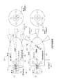
特定の実施形態は、より希薄な混合物を用いてより効果的な燃焼を実現してNOxを低下させる方法及び構造を提供する。図1に示すような特定の実施形態においては、比較的小さな容積内において比較的燃料過剰な混合物170による第1段の燃焼110が行われ、比較的大きな容積において比較的燃料希薄な混合物150による第2段の燃焼120が行われるように従来の予燃焼室を変更してもよい。特定の実施形態においては、第2予燃焼室段120から出て主燃焼室110に入る非常に高エネルギーの火炎ジェット140を発生させる一方で、より低いレベルのNOx形成を特徴とするより効率的な全体的燃焼を2段式予燃焼室100システムにより実現することができる。
Certain embodiments provide methods and structures that achieve more effective combustion using a leaner mixture to reduce NOx. In a particular embodiment, such as that shown in FIG. 1, a
特定の実施形態においては、2段式予燃焼室100システムは、燃料式予燃焼室内において使用される従来のスパークプラグを受動予燃焼室スパークプラグと単に交換し、2段式予燃焼室100システム内に第1段予燃焼室110を提供することによって実現することができる。
In certain embodiments, the two-stage
予燃焼室内において生成されるNOxの量は主に空燃比及び反応物の量によって決定されてもよい。低い空燃比における反応物の量が減少するにつれて、形成されるNOxの量は比例的に減少してもよい。特定の実施形態においては、2段式予燃焼により燃料過剰170段の容積を少なくとも2分の1に低減することができ、それによってNOx生成を約2分の1に低減する。特定の実施形態においては、火炎ジェットエネルギーもまた空燃比及び反応物の量により決定されてもよい。低い空燃比における反応物の量が減少するにつれて、火炎ジェットエネルギーもまた低減されてもよい。2段式予燃焼100の特定の実施形態においては、比較的より希薄な混合物150を特徴とする第2予燃焼室段120は比較的燃料過剰170な第1予燃焼室110段から出る強力な火炎ジェット140により点火される。強力な火炎ジェット140による点火は、第2予燃焼室段120内におけるより希薄な混合物150の迅速な燃焼を生じさせてもよく、これにより、第2予燃焼室段120から高エネルギーの火炎ジェット140を発生させてもよい。これら高エネルギーの火炎ジェット140は、エンジン主燃焼室120内の希薄混合気150に点火し、従来の予燃焼室を用いたシステムと同等のエンジンパワー出力及び熱効率を維持する一方で、低い全体的NOx排出量を実現してもよい。
The amount of NOx produced in the precombustion chamber may be determined mainly by the air / fuel ratio and the amount of reactants. As the amount of reactant at the lower air / fuel ratio decreases, the amount of NOx formed may decrease proportionally. In certain embodiments, the two-stage pre-combustion can reduce the volume of the 170 excess fuel by at least a half, thereby reducing NOx production by about a half. In certain embodiments, the flame jet energy may also be determined by the air / fuel ratio and the amount of reactants. As the amount of reactant at the lower air / fuel ratio decreases, the flame jet energy may also be reduced. In a particular embodiment of the two-
図1に示すような特定の実施形態においては、第1予燃焼室段110の容積は第2予燃焼室段120の容積よりも大幅に小さくてもよい。第1予燃焼室段110の容積は第2予燃焼室段120の容積の約50%未満であってもよい。
In certain embodiments, such as that shown in FIG. 1, the volume of the first
特定の実施形態においては、第1予燃焼室段110又は第2予燃焼室段120のいずれかに、別個の燃料ラインによって直接燃料供給することができる。図1では、より高い燃料濃度はより濃い青で塗りつぶした色によって示される。特定の実施形態においては、図1の上2つの図に示すように第1予燃焼室段110が別個の燃料供給点130によって直接燃料供給される場合、図1の下2つの図に示すようによりも第2予燃焼室120段が別個の燃料供給点130によって直接燃料供給される場合よりも、第1予燃焼室110段内の第1燃料濃度がより過剰となる可能性がある。逆に、第2予燃焼室120段内の第2燃料濃度は、図1の下2つの図に示すようによりも第2予燃焼室120段が別個の燃料供給点130によって直接燃料供給される場合よりも、図1の上2つの図に示すように第1予燃焼室110段が別個の燃料供給点130によって直接燃料供給される場合に、より希薄になる可能性がある。第1予燃焼室110段又は第2予燃焼室120段のいずれかに直接燃料供給することにより、性能が従来の単段式予燃焼室に比べて向上する可能性がある。特定の実施形態においては、受動予燃焼室(PPC:passive prechamber)スパークプラグを第1予燃焼室110段として使用してもよい。特定の実施形態においては、PPCスパークプラグとともに第1予燃焼室段110として燃料供給第2予燃焼室120段を使用してもよい。PPCスパークプラグの例示的な非限定的例は関連の米国特許出願第13/602,148号及び国際出願PCT/US2012/53568号及び国際出願PCT/US2011/002012号に開示されており、これらは参照により本明細書中に組み込まれる。
In certain embodiments, either the first
特定の実施形態においては、第1予燃焼室110段と第2予燃焼室120段と主燃焼室との間の連通は所定の相対的パターン及び角度を有する1以上の孔を介して行われてもよい。特定の実施形態においては、1以上の孔は、第1予燃焼室110段と第2予燃焼室120段との間を連通するための1以上の第1段孔115と、第2予燃焼室120段と主燃焼室との間を連通するための1以上の第2段孔125と、を含んでもよい。特定の実施形態においては、1以上の第1段孔115のそれぞれは第1段孔軸線160を規定してもよく、1以上の第2段孔125のそれぞれは第2段孔軸線160を規定してもよい。各第1段孔軸線160及び各第2段孔軸線160は、インデックス角度610、貫通角度600及び回転オフセット620を規定してもよい。第1段孔115及び第2段孔125のインデックス角度610、貫通角度600及び回転オフセット620は、第1予燃焼室110段内に、第2予燃焼室段120内の第2燃料濃度よりも高い第1燃料濃度を生じさせるように選択してもよい。特定の実施形態においては、2つの予燃焼室段の容積及びアスペクト比は、第1段予燃焼室110内における電極の位置、孔パターン、角度及び別々の燃料供給とともに、第1予燃焼室110段内に、第2予燃焼室120段内の第2燃料濃度よりも大幅に高い第1燃料濃度を形成するように選択してもよい。
In certain embodiments, the communication between the first
図2は、PPCスパークプラグを備えた2段式予燃焼室システム100により達成されたNOx排出量の低下を、従来のスパークプラグを備えた従来の予燃焼室と比較した例示的な結果を示す。図2に示す結果は、この非最適化システムにおいてエンジン熱効率を損なうことなくNOx排出量の低下を実現したことを示す。したがって、PPCスパークプラグを備える最適化された2段式予燃焼室システム100が予燃焼室内のより希薄な混合物によって安定な動作を実現し、結果的に、0.5g/bhp−hrレベルを大幅に下回る非常に低いNOx排出量が得られる可能性は高い。
FIG. 2 shows exemplary results comparing the NOx emissions reduction achieved by the two-stage
特定の実施形態においては、第1予燃焼室110段内の第1燃料濃度及び第2予燃焼室120段内の第2燃料濃度を変更して第2燃料濃度よりも高い第1燃料濃度を得るため、図3〜図13に示される物理的パラメータを単独で又は組み合わせて変更してもよい。
In a specific embodiment, the first fuel concentration in the first
図3に示すように、総容積300は、ポート/孔の容積を含めない予燃焼室スパークプラグ内部の空気の体積として定義されうる。
As shown in FIG. 3, the
図4に示すように、ギャップ400前方の容積は、ギャップの中心からエンドキャップまでの、ポート/孔の容積を含めない予燃焼室スパークプラグ内部の空気の体積として定義されうる。
As shown in FIG. 4, the volume in front of the
図5に示すように、ギャップ500後方の容積は、予燃焼室の後部にある可能性のある任意のポート/孔の容積を含めない、ギャップの中心と予燃焼室の後部との間の予燃焼室スパークプラグ内部の空気の体積として定義されうる。
As shown in FIG. 5, the volume behind the
図6に示すように、貫通角度600は、予燃焼室スパークプラグの軸線160に垂直な面と、ポート/孔の中心線との間の角度として定義されうる。
As shown in FIG. 6, the
図7に示すように、インデックス角度610は、予燃焼室スパークプラグの軸線160と、ポート上において、ポートの中心線が予燃焼室スパークプラグの前面に接触する位置を中心とした回転角として定義されうる。
As shown in FIG. 7, the
図8に示すように、回転オフセット620は、予燃焼室スパークプラグの軸線160及びポート/孔の中心線との間の垂直距離(予燃焼室スパークプラグの前面において測定)として定義されうる。
As shown in FIG. 8, the rotational offset 620 may be defined as the vertical distance (measured at the front of the pre-combustion chamber spark plug) between the pre-combustion chamber
図9に示すように、パターン半径630は、エンドキャップの前面において測定した、予燃焼室スパークプラグの軸線160からポート/孔の中心線までの垂直距離として定義されうる。
As shown in FIG. 9, the
図10に示すように、中心電極から予燃焼室天井までの距離640は、予燃焼室スパークプラグの軸線160に沿った、中心電極の上部からエンドキャップの内側までの距離として定義されうる。
As shown in FIG. 10, the
図11に示すように、ポート長さ650は、ポート/孔の中心線に沿ってエンドキャップの内側からエンドキャップの外側までを測定したポート/孔の長さとして定義されうる。
As shown in FIG. 11,
図12に示すように、ポート直径660はポート/孔の直径として定義されうる。
As shown in FIG. 12, the
図13に示すように、予燃焼室挿入深さ670は、点火デッキ(firing deck)から予燃焼室スパークプラグの端部までの距離として定義されうる。示されるように、図9では、点火デッキはねじ山の端部にあると想定する。
As shown in FIG. 13, the precombustion
Claims (15)
前記第1予燃焼室容積と第2予燃焼室容積との間に連通する1以上の第1段孔と、
前記第1予燃焼室容積内に配置された一次電極と、
前記第1予燃焼室容積内に配置され、前記一次電極からオフセットして1以上の電極ギャップを形成する1以上の接地電極と、を含む第1予燃焼室段と、
前記第2予燃焼室容積を囲む第2予燃焼室段であって、
前記第2予燃焼室容積と燃焼室容積との間に連通する1以上の第2段孔を含む、第2予燃焼室段と、を備え、
前記第1予燃焼室容積が前記第2予燃焼室容積よりも小さく、
前記1以上の第1段孔のそれぞれが第1段孔軸線を規定し、前記1以上の第2段孔のそれぞれが第2段孔軸線を規定し、各第1段孔軸線及び各第2段孔軸線がインデックス角度、貫通角度及び回転オフセットを規定し、前記第1段孔及び前記第2段孔の前記インデックス角度、前記貫通角度及び前記回転オフセットが、前記第2予燃焼室容積内の第2燃料濃度よりも高い前記第1予燃焼室容積内の第1燃料濃度を生じさせるように選択される、2段式予燃焼室。 A first precombustion chamber stage surrounding the first precombustion chamber volume,
One or more first stage holes communicating between the first precombustion chamber volume and the second precombustion chamber volume;
A primary electrode disposed within the first precombustion chamber volume;
A first precombustion chamber stage including one or more ground electrodes disposed within the first precombustion chamber volume and offset from the primary electrode to form one or more electrode gaps;
A second precombustion chamber stage surrounding the second precombustion chamber volume,
A second precombustion chamber stage including one or more second stage holes communicating between the second precombustion chamber volume and the combustion chamber volume ;
The first precombustion chamber volume is smaller than the second precombustion chamber volume;
Each of the one or more first stage holes defines a first stage hole axis, each of the one or more second stage holes defines a second stage hole axis, and each first stage hole axis and each second stage hole axis. A step hole axis defines an index angle, a through angle, and a rotational offset, and the index angle, the through angle, and the rotational offset of the first step hole and the second step hole are within the second precombustion chamber volume. A two- stage precombustion chamber selected to produce a first fuel concentration in the first precombustion chamber volume that is higher than a second fuel concentration .
前記第1予燃焼室容積と第2予燃焼室容積との間に連通する1以上の第1段孔と、
前記第1予燃焼室容積内に配置された一次電極と、
前記第1予燃焼室容積内に配置され、前記一次電極からオフセットして1以上の電極ギャップを形成する1以上の接地電極と、を含む第1予燃焼室段と、
第2予燃焼室段であって、
前記第2予燃焼室容積を囲む外部表面及び内部表面と、
前記内部表面と前記外部表面との間に連通する1以上の第2段孔と、を含む第2予燃焼室段と、を備え、
前記第1予燃焼室容積が前記第2予燃焼室容積よりも小さく、
前記1以上の第1段孔のそれぞれが第1段孔軸線を規定し、前記1以上の第2段孔のそれぞれが第2段孔軸線を規定し、各第1段孔軸線及び各第2段孔軸線がインデックス角度、貫通角度及び回転オフセットを規定し、前記第1段孔及び前記第2段孔の前記インデックス角度、前記貫通角度及び前記回転オフセットが、前記第2予燃焼室容積内の第2燃料濃度よりも高い前記第1予燃焼室容積内の第1燃料濃度を生じさせるように選択される、2段式予燃焼室。 A first precombustion chamber stage surrounding the first precombustion chamber volume,
One or more first stage holes communicating between the first precombustion chamber volume and the second precombustion chamber volume;
A primary electrode disposed within the first precombustion chamber volume;
A first precombustion chamber stage including one or more ground electrodes disposed within the first precombustion chamber volume and offset from the primary electrode to form one or more electrode gaps;
A second pre-combustion chamber stage,
An outer surface and an inner surface surrounding the second pre-combustion chamber volume;
A second pre-combustion chamber stage including one or more second stage holes communicating between the inner surface and the outer surface ;
The first precombustion chamber volume is smaller than the second precombustion chamber volume;
Each of the one or more first stage holes defines a first stage hole axis, each of the one or more second stage holes defines a second stage hole axis, and each first stage hole axis and each second stage hole axis. A step hole axis defines an index angle, a through angle, and a rotational offset, and the index angle, the through angle, and the rotational offset of the first step hole and the second step hole are within the second precombustion chamber volume. A two- stage precombustion chamber selected to produce a first fuel concentration in the first precombustion chamber volume that is higher than a second fuel concentration .
第1予燃焼室容積を囲む第1予燃焼室段であって、
前記第1予燃焼室容積と第2予燃焼室容積との間に連通する1以上の第1段孔と、
前記第1予燃焼室容積内に配置された一次電極と、
前記第1予燃焼室容積内に配置され、前記一次電極からオフセットして1以上の電極ギャップを形成する1以上の接地電極と、を含む第1予燃焼室段と、
前記第2予燃焼室容積を囲む第2予燃焼室段であって、前記第2予燃焼室容積と燃焼室容積との間に連通する1以上の第2段孔を含む第2予燃焼室段と、を備える2段式予燃焼室を提供するステップと、
前記第1予燃焼室容積及び前記第2予燃焼室容積のうち選択した1つに1以上の燃料供給点を導入するステップと、
前記1以上の電極ギャップのうちの少なくとも1つにスパークを発生させて前記第1予燃焼室容積内の燃料空気混合物に点火するステップと、を含み、
前記第1予燃焼室容積が前記第2予燃焼室容積よりも小さく、
前記1以上の第1段孔のそれぞれが第1段孔軸線を規定し、前記1以上の第2段孔のそれぞれが第2段孔軸線を規定し、各第1段孔軸線及び各第2段孔軸線がインデックス角度、貫通角度及び回転オフセットを規定し、前記第1段孔及び前記第2段孔の前記インデックス角度、前記貫通角度及び前記回転オフセットが、前記第1予燃焼室容積内に、前記第2予燃焼室容積内の第2燃料空気混合物よりも高い燃料濃度を有する第1燃料空気混合物を生じさせるように選択される、方法。 A method for reducing NOx levels in a gas engine,
A first precombustion chamber stage surrounding the first precombustion chamber volume,
One or more first stage holes communicating between the first precombustion chamber volume and the second precombustion chamber volume;
A primary electrode disposed within the first precombustion chamber volume;
A first precombustion chamber stage including one or more ground electrodes disposed within the first precombustion chamber volume and offset from the primary electrode to form one or more electrode gaps;
A second pre-combustion chamber stage surrounding the second pre-combustion chamber volume, the second pre-combustion chamber including one or more second stage holes communicating between the second pre-combustion chamber volume and the combustion chamber volume Providing a two-stage pre-combustion chamber comprising:
Introducing one or more fuel supply points into a selected one of the first pre-combustion chamber volume and the second pre-combustion chamber volume;
Look including the steps of: igniting the fuel-air mixture of the first pre-combustion chamber volume to generate a spark to at least one of the one or more electrode gap,
The first precombustion chamber volume is smaller than the second precombustion chamber volume;
Each of the one or more first stage holes defines a first stage hole axis, each of the one or more second stage holes defines a second stage hole axis, and each first stage hole axis and each second stage hole axis. A step hole axis defines an index angle, a through angle, and a rotation offset, and the index angle, the through angle, and the rotation offset of the first step hole and the second step hole are within the first precombustion chamber volume. , Selected to produce a first fuel air mixture having a higher fuel concentration than a second fuel air mixture in the second precombustion chamber volume .
第1予燃焼室容積を囲む第1予燃焼室段であって、
前記第1予燃焼室容積と第2予燃焼室容積との間に連通する1以上の第1段孔と、
前記第1予燃焼室容積内に配置された一次電極と、
前記第1予燃焼室容積内に配置され、前記一次電極からオフセットして1以上の電極ギャップを形成する1以上の接地電極と、を含む第1予燃焼室段と、
第2予燃焼室段であって、
前記第2予燃焼室容積を囲む外部表面及び内部表面と、
前記内部表面と前記外部表面との間に連通する1以上の第2段孔と、を含む第2予燃焼室段と、を備える2段式予燃焼室を提供するステップと、
前記第1予燃焼室容積及び前記第2予燃焼室容積のうち選択した1つに1以上の燃料入充填流を導入するステップと、
前記1以上の電極ギャップのうちの少なくとも1つにスパークを発生させて前記第1予燃焼室容積内の燃料空気混合物に点火するステップと、を含み、
前記第1予燃焼室容積が前記第2予燃焼室容積よりも小さく、
前記1以上の第1段孔のそれぞれが第1段孔軸線を規定し、前記1以上の第2段孔のそれぞれが第2段孔軸線を規定し、各第1段孔軸線及び各第2段孔軸線がインデックス角度、貫通角度及び回転オフセットを規定し、前記第1段孔及び前記第2段孔の前記インデックス角度、前記貫通角度及び前記回転オフセットが、前記第1予燃焼室容積内に、前記第2予燃焼室容積内の第2燃料空気混合物よりも高い燃料濃度を有する第1燃料空気混合物を生じさせるように選択される、方法。 A method for reducing NOx levels in a gas engine,
A first precombustion chamber stage surrounding the first precombustion chamber volume,
One or more first stage holes communicating between the first precombustion chamber volume and the second precombustion chamber volume;
A primary electrode disposed within the first precombustion chamber volume;
A first precombustion chamber stage including one or more ground electrodes disposed within the first precombustion chamber volume and offset from the primary electrode to form one or more electrode gaps;
A second pre-combustion chamber stage,
An outer surface and an inner surface surrounding the second pre-combustion chamber volume;
Providing a two-stage pre-combustion chamber comprising: a second pre-combustion chamber stage including one or more second stage holes communicating between the inner surface and the outer surface;
Introducing one or more fuel charge flows into a selected one of the first precombustion chamber volume and the second precombustion chamber volume;
Look including the steps of: igniting the fuel-air mixture of the first pre-combustion chamber volume to generate a spark to at least one of the one or more electrode gap,
The first precombustion chamber volume is smaller than the second precombustion chamber volume;
Each of the one or more first stage holes defines a first stage hole axis, each of the one or more second stage holes defines a second stage hole axis, and each first stage hole axis and each second stage hole axis. A step hole axis defines an index angle, a through angle, and a rotation offset, and the index angle, the through angle, and the rotation offset of the first step hole and the second step hole are within the first precombustion chamber volume. , Selected to produce a first fuel air mixture having a higher fuel concentration than a second fuel air mixture in the second precombustion chamber volume .
Applications Claiming Priority (3)
| Application Number | Priority Date | Filing Date | Title |
|---|---|---|---|
| US201261697628P | 2012-09-06 | 2012-09-06 | |
| US61/697,628 | 2012-09-06 | ||
| PCT/US2013/058635 WO2014039915A1 (en) | 2012-09-06 | 2013-09-06 | Two-stage precombustion chamber for large bore gas engines |
Publications (2)
| Publication Number | Publication Date |
|---|---|
| JP2015530514A JP2015530514A (en) | 2015-10-15 |
| JP6175143B2 true JP6175143B2 (en) | 2017-08-02 |
Family
ID=50185681
Family Applications (1)
| Application Number | Title | Priority Date | Filing Date |
|---|---|---|---|
| JP2015531265A Active JP6175143B2 (en) | 2012-09-06 | 2013-09-06 | 2-stage pre-combustion chamber for large-diameter gas engines |
Country Status (5)
| Country | Link |
|---|---|
| US (2) | US10138799B2 (en) |
| EP (2) | EP2893601A4 (en) |
| JP (1) | JP6175143B2 (en) |
| CA (1) | CA2882848C (en) |
| WO (1) | WO2014039915A1 (en) |
Families Citing this family (14)
| Publication number | Priority date | Publication date | Assignee | Title |
|---|---|---|---|---|
| US9500118B2 (en) | 2011-09-03 | 2016-11-22 | Prometheus Applied Technologies, Llc | Method and apparatus for achieving high power flame jets while reducing quenching and autoignition in prechamber spark plugs for gas engines |
| EP2751408B1 (en) | 2011-09-03 | 2024-03-20 | Prometheus Applied Technologies, LLC | Method and apparatus for achieving high power flame jets and reducing quenching and autoignition in prechamber spark plugs for gas engines |
| US9593622B2 (en) | 2015-02-09 | 2017-03-14 | Caterpillar Inc. | Combustion system, nozzle for prechamber assembly, and method of making same |
| US10066580B2 (en) * | 2015-10-15 | 2018-09-04 | The Regents Of The University Of Michigan | Lean burn internal combustion engine |
| US10208651B2 (en) | 2016-02-06 | 2019-02-19 | Prometheus Applied Technologies, Llc | Lean-burn pre-combustion chamber |
| EP3261199A1 (en) * | 2016-06-23 | 2017-12-27 | Fuelsave GmbH | Prechamber spark plug and a method for operating a pre-chamber sparkplug |
| JP6895243B2 (en) | 2016-12-08 | 2021-06-30 | 三菱重工エンジン&ターボチャージャ株式会社 | Sub-chamber gas engine |
| WO2018144498A1 (en) | 2017-02-06 | 2018-08-09 | Cummins Inc. | Engine system for emission reduction without aftertreatment |
| DE102017107683A1 (en) | 2017-04-10 | 2018-10-11 | Federal-Mogul Ignition Gmbh | Internal combustion engine with a prechamber spark plug |
| DE102017107679B4 (en) | 2017-04-10 | 2020-03-26 | Federal-Mogul Ignition Gmbh | Prechamber spark plug for an internal combustion engine |
| US10833485B2 (en) | 2018-12-06 | 2020-11-10 | Federal-Mogul Ignition Gmbh | Pre-chamber spark plug |
| CN110714867B (en) * | 2019-11-21 | 2021-03-16 | 清华大学 | Ignition device, combustion system and combustion method of internal combustion engine |
| DE102022109745B3 (en) | 2022-04-22 | 2023-03-30 | Dr. Ing. H.C. F. Porsche Aktiengesellschaft | Device for igniting a fuel-air mixture |
| DE102022209529A1 (en) | 2022-09-13 | 2024-03-14 | Dkt Verwaltungs-Gmbh | Prechamber element, ignition device and method for assembling an ignition device |
Family Cites Families (26)
| Publication number | Priority date | Publication date | Assignee | Title |
|---|---|---|---|---|
| US1422794A (en) * | 1920-01-19 | 1922-07-11 | Smith Frederick Arthur | Ignition device for internal-combustion engines |
| US1633384A (en) * | 1921-07-25 | 1927-06-21 | Worthington Pump & Mach Corp | Internal-combustion engine |
| US1660424A (en) * | 1925-12-30 | 1928-02-28 | Modersohn Fritz | Arrangement of precombustion chamber for injection-oil engines |
| US1877737A (en) * | 1928-08-30 | 1932-09-13 | Fairbanks Morse & Co | Combustion chamber |
| US2456080A (en) * | 1944-11-20 | 1948-12-14 | Pe Wu | Ignition plug |
| US2991768A (en) * | 1953-04-02 | 1961-07-11 | Julius E Witzky | Pre-combustion chamber for internal combustion engines |
| US4174679A (en) * | 1976-05-27 | 1979-11-20 | Toyota Jidosha Kogyo Kabushiki Kaisha | Internal combustion engine with a subsidiary combustion chamber |
| JPS52144508A (en) * | 1976-05-27 | 1977-12-01 | Toyota Motor Corp | Internal combustion engine attached with aulixiary combustion room |
| JPS5320005A (en) * | 1976-08-08 | 1978-02-23 | Nippon Soken Inc | Internal combustion engine |
| US4124000A (en) * | 1976-11-03 | 1978-11-07 | General Motors Corporation | Mixed cycle stratified charge engine with ignition antechamber |
| JPS5440308U (en) * | 1977-08-25 | 1979-03-17 | ||
| US4218993A (en) * | 1979-03-14 | 1980-08-26 | Blackburn Donald E | Method and apparatus for accomplishing flame ignition for an internal combustion engine |
| US4696269A (en) * | 1985-12-09 | 1987-09-29 | Oak Ridge Systems, Inc. | Device for improving the ignition of fuel-air mixtures in internal combustion engines |
| US4930473A (en) * | 1988-12-09 | 1990-06-05 | Texas Ignitors Company, Inc. | Swirl chamber and spark plug assembly |
| JP2567875Y2 (en) * | 1989-09-01 | 1998-04-08 | 三菱重工業株式会社 | Spark ignition gas engine |
| US5060609A (en) * | 1989-12-06 | 1991-10-29 | Dan Merritt | Internal combustion engine |
| US5222993A (en) * | 1992-09-28 | 1993-06-29 | Gas Research Institute | Ignition system for water-cooled gas engines |
| EP1766208B1 (en) * | 2004-06-24 | 2019-12-25 | Woodward, Inc. | Pre-chamber spark plug |
| US20060219210A1 (en) | 2005-03-30 | 2006-10-05 | Brett Bailey | Internal combustion engine with variable volume prechamber |
| US7922551B2 (en) | 2005-06-07 | 2011-04-12 | Woodward, Inc. | Pre-chamber spark plug |
| WO2009149044A2 (en) | 2008-06-03 | 2009-12-10 | Bryant, Mark, Curtis | Internal combustion engine and working cycle |
| US9172217B2 (en) * | 2010-11-23 | 2015-10-27 | Woodward, Inc. | Pre-chamber spark plug with tubular electrode and method of manufacturing same |
| US9476347B2 (en) | 2010-11-23 | 2016-10-25 | Woodward, Inc. | Controlled spark ignited flame kernel flow in fuel-fed prechambers |
| EP2659556B1 (en) * | 2010-12-31 | 2018-05-23 | Prometheus Applied Technologies, LLC | Prechamber ignition system |
| EP2751408B1 (en) * | 2011-09-03 | 2024-03-20 | Prometheus Applied Technologies, LLC | Method and apparatus for achieving high power flame jets and reducing quenching and autoignition in prechamber spark plugs for gas engines |
| US8839762B1 (en) * | 2013-06-10 | 2014-09-23 | Woodward, Inc. | Multi-chamber igniter |
-
2013
- 2013-09-06 WO PCT/US2013/058635 patent/WO2014039915A1/en unknown
- 2013-09-06 EP EP13835622.5A patent/EP2893601A4/en not_active Ceased
- 2013-09-06 US US14/020,770 patent/US10138799B2/en active Active
- 2013-09-06 JP JP2015531265A patent/JP6175143B2/en active Active
- 2013-09-06 CA CA2882848A patent/CA2882848C/en active Active
- 2013-09-06 EP EP19156273.5A patent/EP3530903A1/en active Pending
-
2017
- 2017-10-14 US US15/784,095 patent/US20180038270A1/en not_active Abandoned
Also Published As
| Publication number | Publication date |
|---|---|
| US20180038270A1 (en) | 2018-02-08 |
| CA2882848C (en) | 2018-01-09 |
| US20140060479A1 (en) | 2014-03-06 |
| CA2882848A1 (en) | 2014-03-13 |
| EP2893601A1 (en) | 2015-07-15 |
| US10138799B2 (en) | 2018-11-27 |
| WO2014039915A1 (en) | 2014-03-13 |
| JP2015530514A (en) | 2015-10-15 |
| EP2893601A4 (en) | 2015-08-26 |
| EP3530903A1 (en) | 2019-08-28 |
Similar Documents
| Publication | Publication Date | Title |
|---|---|---|
| JP6175143B2 (en) | 2-stage pre-combustion chamber for large-diameter gas engines | |
| EP2751408B1 (en) | Method and apparatus for achieving high power flame jets and reducing quenching and autoignition in prechamber spark plugs for gas engines | |
| US10208651B2 (en) | Lean-burn pre-combustion chamber | |
| US9500118B2 (en) | Method and apparatus for achieving high power flame jets while reducing quenching and autoignition in prechamber spark plugs for gas engines | |
| JP6236520B2 (en) | Active scavenging prechamber | |
| JP4501950B2 (en) | Combustion control device for internal combustion engine | |
| ES2681220T3 (en) | Prechamber ignition system | |
| KR20140040666A (en) | Pre-chamber system for an internal combustion engine | |
| CN107339149A (en) | Internal combustion engine | |
| JP2008133759A (en) | Sub-chamber type internal combustion engine | |
| EP2998537A1 (en) | Pre-chamber of internal combustion engine | |
| JP2007297942A (en) | Ignition device for internal combustion engine | |
| JP6498223B2 (en) | Lean combustion pre-combustion chamber | |
| CN110714867B (en) | Ignition device, combustion system and combustion method of internal combustion engine | |
| JP2010242740A (en) | Internal combustion engine | |
| EP3037646B1 (en) | Method for operating internal combustion engines | |
| JP5995748B2 (en) | Sub-chamber type gas engine and operation control method thereof | |
| JP4457999B2 (en) | In-cylinder internal combustion engine | |
| KR20130087666A (en) | Pre-chamber for gas engine and control method thereof | |
| JP2010116910A (en) | Internal combustion engine including plasma igniter | |
| JP2009191732A (en) | Plasma jet ignition internal combustion engine |
Legal Events
| Date | Code | Title | Description |
|---|---|---|---|
| A131 | Notification of reasons for refusal |
Free format text: JAPANESE INTERMEDIATE CODE: A131 Effective date: 20160418 |
|
| A601 | Written request for extension of time |
Free format text: JAPANESE INTERMEDIATE CODE: A601 Effective date: 20160712 |
|
| A521 | Request for written amendment filed |
Free format text: JAPANESE INTERMEDIATE CODE: A523 Effective date: 20160916 |
|
| A131 | Notification of reasons for refusal |
Free format text: JAPANESE INTERMEDIATE CODE: A131 Effective date: 20170201 |
|
| A521 | Request for written amendment filed |
Free format text: JAPANESE INTERMEDIATE CODE: A523 Effective date: 20170413 |
|
| TRDD | Decision of grant or rejection written | ||
| A01 | Written decision to grant a patent or to grant a registration (utility model) |
Free format text: JAPANESE INTERMEDIATE CODE: A01 Effective date: 20170629 |
|
| A61 | First payment of annual fees (during grant procedure) |
Free format text: JAPANESE INTERMEDIATE CODE: A61 Effective date: 20170707 |
|
| R150 | Certificate of patent or registration of utility model |
Ref document number: 6175143 Country of ref document: JP Free format text: JAPANESE INTERMEDIATE CODE: R150 |
|
| R250 | Receipt of annual fees |
Free format text: JAPANESE INTERMEDIATE CODE: R250 |
|
| R250 | Receipt of annual fees |
Free format text: JAPANESE INTERMEDIATE CODE: R250 |
|
| R250 | Receipt of annual fees |
Free format text: JAPANESE INTERMEDIATE CODE: R250 |
|
| R250 | Receipt of annual fees |
Free format text: JAPANESE INTERMEDIATE CODE: R250 |