JP6174259B2 - A kind of rotary engine - Google Patents
A kind of rotary engine Download PDFInfo
- Publication number
- JP6174259B2 JP6174259B2 JP2016530166A JP2016530166A JP6174259B2 JP 6174259 B2 JP6174259 B2 JP 6174259B2 JP 2016530166 A JP2016530166 A JP 2016530166A JP 2016530166 A JP2016530166 A JP 2016530166A JP 6174259 B2 JP6174259 B2 JP 6174259B2
- Authority
- JP
- Japan
- Prior art keywords
- movable
- cylinder main
- main body
- rotor
- rotary engine
- Prior art date
- Legal status (The legal status is an assumption and is not a legal conclusion. Google has not performed a legal analysis and makes no representation as to the accuracy of the status listed.)
- Expired - Fee Related
Links
- 230000007246 mechanism Effects 0.000 claims description 33
- 230000005540 biological transmission Effects 0.000 claims description 25
- 230000004913 activation Effects 0.000 claims description 11
- 238000007789 sealing Methods 0.000 claims description 3
- 238000007906 compression Methods 0.000 description 36
- 230000006835 compression Effects 0.000 description 35
- 239000007858 starting material Substances 0.000 description 12
- 238000000926 separation method Methods 0.000 description 7
- 230000000694 effects Effects 0.000 description 6
- 239000000295 fuel oil Substances 0.000 description 6
- 238000004519 manufacturing process Methods 0.000 description 5
- 239000000446 fuel Substances 0.000 description 2
- 238000002347 injection Methods 0.000 description 2
- 239000007924 injection Substances 0.000 description 2
- 238000000034 method Methods 0.000 description 2
- 230000001360 synchronised effect Effects 0.000 description 2
- 230000009286 beneficial effect Effects 0.000 description 1
- 238000006243 chemical reaction Methods 0.000 description 1
- 238000002485 combustion reaction Methods 0.000 description 1
- 238000010586 diagram Methods 0.000 description 1
- 230000013011 mating Effects 0.000 description 1
- 238000003825 pressing Methods 0.000 description 1
- 230000008569 process Effects 0.000 description 1
- 230000008439 repair process Effects 0.000 description 1
- 239000000243 solution Substances 0.000 description 1
Images


Classifications
-
- F—MECHANICAL ENGINEERING; LIGHTING; HEATING; WEAPONS; BLASTING
- F02—COMBUSTION ENGINES; HOT-GAS OR COMBUSTION-PRODUCT ENGINE PLANTS
- F02B—INTERNAL-COMBUSTION PISTON ENGINES; COMBUSTION ENGINES IN GENERAL
- F02B55/00—Internal-combustion aspects of rotary pistons; Outer members for co-operation with rotary pistons
- F02B55/02—Pistons
-
- F—MECHANICAL ENGINEERING; LIGHTING; HEATING; WEAPONS; BLASTING
- F02—COMBUSTION ENGINES; HOT-GAS OR COMBUSTION-PRODUCT ENGINE PLANTS
- F02B—INTERNAL-COMBUSTION PISTON ENGINES; COMBUSTION ENGINES IN GENERAL
- F02B53/00—Internal-combustion aspects of rotary-piston or oscillating-piston engines
- F02B53/12—Ignition
-
- F—MECHANICAL ENGINEERING; LIGHTING; HEATING; WEAPONS; BLASTING
- F01—MACHINES OR ENGINES IN GENERAL; ENGINE PLANTS IN GENERAL; STEAM ENGINES
- F01C—ROTARY-PISTON OR OSCILLATING-PISTON MACHINES OR ENGINES
- F01C21/00—Component parts, details or accessories not provided for in groups F01C1/00 - F01C20/00
- F01C21/008—Driving elements, brakes, couplings, transmissions specially adapted for rotary or oscillating-piston machines or engines
-
- F—MECHANICAL ENGINEERING; LIGHTING; HEATING; WEAPONS; BLASTING
- F01—MACHINES OR ENGINES IN GENERAL; ENGINE PLANTS IN GENERAL; STEAM ENGINES
- F01C—ROTARY-PISTON OR OSCILLATING-PISTON MACHINES OR ENGINES
- F01C21/00—Component parts, details or accessories not provided for in groups F01C1/00 - F01C20/00
- F01C21/02—Arrangements of bearings
-
- F—MECHANICAL ENGINEERING; LIGHTING; HEATING; WEAPONS; BLASTING
- F01—MACHINES OR ENGINES IN GENERAL; ENGINE PLANTS IN GENERAL; STEAM ENGINES
- F01C—ROTARY-PISTON OR OSCILLATING-PISTON MACHINES OR ENGINES
- F01C21/00—Component parts, details or accessories not provided for in groups F01C1/00 - F01C20/00
- F01C21/08—Rotary pistons
-
- F—MECHANICAL ENGINEERING; LIGHTING; HEATING; WEAPONS; BLASTING
- F01—MACHINES OR ENGINES IN GENERAL; ENGINE PLANTS IN GENERAL; STEAM ENGINES
- F01C—ROTARY-PISTON OR OSCILLATING-PISTON MACHINES OR ENGINES
- F01C21/00—Component parts, details or accessories not provided for in groups F01C1/00 - F01C20/00
- F01C21/10—Outer members for co-operation with rotary pistons; Casings
- F01C21/104—Stators; Members defining the outer boundaries of the working chamber
- F01C21/106—Stators; Members defining the outer boundaries of the working chamber with a radial surface, e.g. cam rings
-
- F—MECHANICAL ENGINEERING; LIGHTING; HEATING; WEAPONS; BLASTING
- F01—MACHINES OR ENGINES IN GENERAL; ENGINE PLANTS IN GENERAL; STEAM ENGINES
- F01C—ROTARY-PISTON OR OSCILLATING-PISTON MACHINES OR ENGINES
- F01C21/00—Component parts, details or accessories not provided for in groups F01C1/00 - F01C20/00
- F01C21/18—Arrangements for admission or discharge of the working fluid, e.g. constructional features of the inlet or outlet
-
- F—MECHANICAL ENGINEERING; LIGHTING; HEATING; WEAPONS; BLASTING
- F01—MACHINES OR ENGINES IN GENERAL; ENGINE PLANTS IN GENERAL; STEAM ENGINES
- F01C—ROTARY-PISTON OR OSCILLATING-PISTON MACHINES OR ENGINES
- F01C9/00—Oscillating-piston machines or engines
- F01C9/002—Oscillating-piston machines or engines the piston oscillating around a fixed axis
-
- F—MECHANICAL ENGINEERING; LIGHTING; HEATING; WEAPONS; BLASTING
- F02—COMBUSTION ENGINES; HOT-GAS OR COMBUSTION-PRODUCT ENGINE PLANTS
- F02B—INTERNAL-COMBUSTION PISTON ENGINES; COMBUSTION ENGINES IN GENERAL
- F02B55/00—Internal-combustion aspects of rotary pistons; Outer members for co-operation with rotary pistons
- F02B55/08—Outer members for co-operation with rotary pistons; Casings
-
- F—MECHANICAL ENGINEERING; LIGHTING; HEATING; WEAPONS; BLASTING
- F02—COMBUSTION ENGINES; HOT-GAS OR COMBUSTION-PRODUCT ENGINE PLANTS
- F02B—INTERNAL-COMBUSTION PISTON ENGINES; COMBUSTION ENGINES IN GENERAL
- F02B63/00—Adaptations of engines for driving pumps, hand-held tools or electric generators; Portable combinations of engines with engine-driven devices
- F02B63/06—Adaptations of engines for driving pumps, hand-held tools or electric generators; Portable combinations of engines with engine-driven devices for pumps
-
- F—MECHANICAL ENGINEERING; LIGHTING; HEATING; WEAPONS; BLASTING
- F02—COMBUSTION ENGINES; HOT-GAS OR COMBUSTION-PRODUCT ENGINE PLANTS
- F02N—STARTING OF COMBUSTION ENGINES; STARTING AIDS FOR SUCH ENGINES, NOT OTHERWISE PROVIDED FOR
- F02N11/00—Starting of engines by means of electric motors
- F02N11/08—Circuits or control means specially adapted for starting of engines
-
- F—MECHANICAL ENGINEERING; LIGHTING; HEATING; WEAPONS; BLASTING
- F04—POSITIVE - DISPLACEMENT MACHINES FOR LIQUIDS; PUMPS FOR LIQUIDS OR ELASTIC FLUIDS
- F04C—ROTARY-PISTON, OR OSCILLATING-PISTON, POSITIVE-DISPLACEMENT MACHINES FOR LIQUIDS; ROTARY-PISTON, OR OSCILLATING-PISTON, POSITIVE-DISPLACEMENT PUMPS
- F04C23/00—Combinations of two or more pumps, each being of rotary-piston or oscillating-piston type, specially adapted for elastic fluids; Pumping installations specially adapted for elastic fluids; Multi-stage pumps specially adapted for elastic fluids
- F04C23/008—Hermetic pumps
-
- F—MECHANICAL ENGINEERING; LIGHTING; HEATING; WEAPONS; BLASTING
- F04—POSITIVE - DISPLACEMENT MACHINES FOR LIQUIDS; PUMPS FOR LIQUIDS OR ELASTIC FLUIDS
- F04C—ROTARY-PISTON, OR OSCILLATING-PISTON, POSITIVE-DISPLACEMENT MACHINES FOR LIQUIDS; ROTARY-PISTON, OR OSCILLATING-PISTON, POSITIVE-DISPLACEMENT PUMPS
- F04C29/00—Component parts, details or accessories of pumps or pumping installations, not provided for in groups F04C18/00 - F04C28/00
- F04C29/04—Heating; Cooling; Heat insulation
-
- Y—GENERAL TAGGING OF NEW TECHNOLOGICAL DEVELOPMENTS; GENERAL TAGGING OF CROSS-SECTIONAL TECHNOLOGIES SPANNING OVER SEVERAL SECTIONS OF THE IPC; TECHNICAL SUBJECTS COVERED BY FORMER USPC CROSS-REFERENCE ART COLLECTIONS [XRACs] AND DIGESTS
- Y02—TECHNOLOGIES OR APPLICATIONS FOR MITIGATION OR ADAPTATION AGAINST CLIMATE CHANGE
- Y02T—CLIMATE CHANGE MITIGATION TECHNOLOGIES RELATED TO TRANSPORTATION
- Y02T10/00—Road transport of goods or passengers
- Y02T10/10—Internal combustion engine [ICE] based vehicles
- Y02T10/12—Improving ICE efficiencies
Description
本発明は、一種のエンジンに係り、具体的に言うと、一種のロータリーエンジンに係る。 The present invention relates to a kind of engine, and more specifically to a kind of rotary engine.
現在、市場において最も広く応用されているエンジンは、四ストロークピストン往複式エンジンである。但し、もう一種の知名度が高いが、応用が極めて少ないエンジンがあり、即ち、ロータリーエンジンである。 At present, the most widely applied engine on the market is a four-stroke piston reciprocating engine. However, there is another kind of high-profile engine that has very few applications, that is, a rotary engine.
ローターエンジンは、伝統的な往複式エンジンと同じように、皆空気燃焼混合ガスの燃焼により発生する膨張圧力を利用することによって、回転力を取得する。二種のエンジンの機構差異は、膨張圧力の使用方式である。往複式エンジンにおいて、ピストン頂部表面に発生する膨張不全は、ピストンを下へ押すので、機械力を連接棒に伝導し、クランクを駆動して回転させる;ローターエンジンの膨張圧力は、ローターの側面に働きかけ、ローターを駆動して回転させる。 The rotor engine obtains rotational force by utilizing the expansion pressure generated by the combustion of the air-burning mixed gas, as in the case of a traditional double-duplex engine. The mechanism difference between the two engines is the way in which the expansion pressure is used. In a double engine, the expansion failure that occurs on the top surface of the piston pushes the piston down, so that mechanical force is transmitted to the connecting rod and the crank is driven to rotate; the expansion pressure of the rotor engine is applied to the side of the rotor Engage and drive the rotor to rotate.
ローターエンジンは、伝統的な往複式エンジンと比べて、ローターエンジンの優位性は、エンジン回転速度が高く、質量が低く、体積が小さく、リットル毎のパワーが高く、その上、運転が安定て振動騒音が小さいことである。 Rotor engines are superior to traditional double-duplex engines in that rotor engines have high engine speed, low mass, small volume, high power per liter, and stable operation and vibration. The noise is low.
現存のロータリーエンジンの中で、三角ロータリーエンジンは大きな比例を占めているが、構造が複雑で、製造要求が高く、シリンダー内の圧縮比を調整し難く、燃料油消費量が大きく、その上、その動力が不足である。 Among the existing rotary engines, the triangular rotary engine occupies a large proportion, but the structure is complicated, the manufacturing requirements are high, the compression ratio in the cylinder is difficult to adjust, the fuel oil consumption is large, The power is insufficient.
技術背景の不足を克服するために、本発明は、一種のロータリーエンジンを提供し、現存のロータリーエンジンにおいて存在している構造が複雑で、燃料油消費量が大きく、それに加えて、動力が不足している問題を解決する。 In order to overcome the shortage of technical background, the present invention provides a kind of rotary engine, the structure existing in the existing rotary engine is complicated, the fuel oil consumption is large, and in addition, the power is insufficient. Solve the problem.
本発明で採用する技術案は、下記の通りである。一種のロータリーエンジンであり、シリンダー主体、ローター及びシリンダー主体に設置されているガス入口、ガス出口とイグニッション装置を含む;[2]前記シリンダー主体内に、少なくとも一組の可動バッフルが設置され、シリンダー壁と嵌め合うことによって、少なくとも二つの密封キャビティを形成する;前記可動バッフルがシリンダー主体の中心を軸に回転できる;前記可動バッフルとローターの間に、単一方向の回転機構が設置され、ローターを駆動して単一方向で回転させる。 The technical solution adopted in the present invention is as follows. A type of rotary engine, including a cylinder main body, a rotor and a gas inlet, a gas outlet and an ignition device installed in the cylinder main body; [2] At least one set of movable baffles is installed in the cylinder main body, and the cylinder By mating with the wall, at least two sealed cavities are formed; the movable baffle can rotate about the center of the cylinder main body; a unidirectional rotating mechanism is installed between the movable baffle and the rotor, and the rotor To rotate in a single direction.
また固定バッフルを含み、一組の前記可動バッフルが設置され、シリンダー主体の中心を軸に往復で回転できる。 In addition, a fixed baffle is included, and a set of the movable baffles is installed and can be rotated reciprocally around the center of the cylinder main body.
前記の一組の可動バッフルが二つの内分離刃及び内分離刃を固定するディスクを含み、前記ディスク中心位置に、回転軸も設置されている。 The set of movable baffles includes two inner separating blades and a disk for fixing the inner separating blade, and a rotating shaft is also installed at the center of the disk.
単一方向回転機構が回転軸に設置され、それに加えて、方向が逆である第一単一方向ベアリングと第二単一方向ベアリングであり、前記第一単一方向ベアリングと第二単一方向ベアリングがそれぞれ二組の異なる伝動機構を通じてローターと接続し、その中で、一組の伝動機構がローターを駆動して第一単一方向ベアリングと同方向で回転させ、その他一組の伝動機構がローターを駆動して第二単一方向ベアリングと逆方向で回転させる。 A first unidirectional bearing and a second unidirectional bearing, wherein a unidirectional rotating mechanism is installed on the axis of rotation and in addition, the directions are reversed, the first unidirectional bearing and the second unidirectional bearing; Each bearing is connected to the rotor through two different sets of transmission mechanisms, in which one set of transmission mechanisms drives the rotor to rotate in the same direction as the first unidirectional bearing, and the other set of transmission mechanisms Drive the rotor to rotate in the opposite direction to the second unidirectional bearing.
ローターを駆動して第一単一方向ベアリングと同方向で回転させる伝動機構がベルト伝動機構であり、ローターを駆動して第二単一方向ベアリングと逆方向で回転させる伝動機構が歯車かみ合い伝動機構である。 The transmission mechanism that drives the rotor and rotates in the same direction as the first unidirectional bearing is the belt transmission mechanism, and the transmission mechanism that drives the rotor and rotates in the opposite direction to the second unidirectional bearing is the gear meshing transmission mechanism. It is.
固定バッフルとシリンダー主体が一体化構造であり、それに加えて、ガス入口、ガス出口とイグニッション装置が固定バッフルに設置されている。 The fixed baffle and the cylinder main body have an integrated structure, and in addition, a gas inlet, a gas outlet, and an ignition device are installed in the fixed baffle.
前記シリンダー主体内に、二組のバッフルが設置され、当該二組の可動バッフルが皆シリンダー主体中心を軸に回って単一方向に同方向で回転する。 Two sets of baffles are installed in the cylinder main body, and the two sets of movable baffles all rotate around the cylinder main center in the same direction in a single direction.
前記の一組の可動バッフルが二つの内分離刃及び内分離刃を固定するディスクを含み、前記ローターがシリンダー主体中心に設置され、前記ディスクがローターに嵌められている。 The set of movable baffles includes two inner separating blades and a disk for fixing the inner separating blade, the rotor is installed at the center of the cylinder main body, and the disk is fitted to the rotor.
前記ディスクがシリンダー主体の同じ側に設置されている。 The disc is installed on the same side of the cylinder body.
前記の一組の可動バッフルが一つの内分離刃及び内分離刃を固定するディスクを含み、前記ローターがシリンダー主体中心に設置され、前記ディスクがローターに嵌められている。 The set of movable baffles includes an inner separating blade and a disk for fixing the inner separating blade, the rotor is installed at the center of the cylinder main body, and the disk is fitted to the rotor.
前記シリンダー主体が二つ設置され、それに加えて、重ね合わせた配置され、その中の一つのシリンダー主体内の可動バッフルがその他のシリンダー主体内の可動バッフルと固定に接続する。 Two cylinder main bodies are installed, and in addition to these, the movable baffles in one cylinder main body are fixedly connected to the movable baffles in the other cylinder main bodies.
前記単一方向回転機構が第一可動歯及び第二可動歯を含み、前記シリンダー主体の直径方向に第一可動歯取付用第一滑り溝が設置され、第一可動歯が第一滑り溝と滑りはめ合いを行い、第一可動歯の一端で弾性戻り部品と接続し、その他の一端が斜面である;前記ローターの直径方向に第二可動歯取付用第二滑り溝が設置され、その中で、第二可動歯が第二滑り溝と滑りはめ合いを行い、第二可動歯の一端で弾性戻り部品と接続し、その他の一端が第一可動歯方向と逆な斜面である。 The unidirectional rotation mechanism includes a first movable tooth and a second movable tooth, a first sliding groove for mounting a first movable tooth is installed in a diameter direction of the cylinder main body, and the first movable tooth is a first sliding groove. A slip fit is made, one end of the first movable tooth is connected to the elastic return part, and the other end is a slope; a second sliding groove for mounting the second movable tooth is installed in the diameter direction of the rotor, Thus, the second movable tooth makes a sliding fit with the second sliding groove, is connected to the elastic return component at one end of the second movable tooth, and the other end is a slope opposite to the first movable tooth direction.
前記第一可動歯と第二可動歯がシリンダー主体の外部に設置され、前記第一可動歯と第二可動歯との間に外分離刃が設置され、前記外分離刃がディスクと接続する。 The first movable tooth and the second movable tooth are installed outside the cylinder main body, an outer separation blade is installed between the first movable tooth and the second movable tooth, and the outer separation blade is connected to the disk.
ガス入口、ガス出口とイグニッション装置が複数の組が設置され、それに加えて、シリンダー主体外周に均一に密集に分布している。 A plurality of sets of gas inlets, gas outlets, and ignition devices are installed, and in addition, the gas inlets, gas outlets, and ignition devices are uniformly and densely distributed around the cylinder main body.
また二組の可動バッフルの間において、間歇伝動を行う間歇伝動機構がを含む。 Moreover, the intermittent transmission mechanism which performs an intermittent transmission between two sets of movable baffles is included.
また起動装置を含み、前記起動装置が起動モーターと起動コイルを含み、前記可動バッフルに、起動モーターと連動する接続タンクが設置され、それに加えて、起動コイルと嵌め合うカムブロックが設置されている。 In addition, a starter is included, the starter includes a starter motor and a starter coil, a connection tank interlocking with the starter motor is installed in the movable baffle, and in addition, a cam block that fits the starter coil is installed. .
前記可動バッフルに触発感応装置も設置されている。 An inspiration sensitive device is also installed on the movable baffle.
前記シリンダー主体及びそのシリンダー主体内の可動バッフルが複数の組で重ね合わせて配置されることができる。 The cylinder main body and the movable baffle in the cylinder main body may be arranged in a superposed manner in a plurality of sets.
一種のコンプレッサーであり、圧縮コンポーネントとローターエンジンを含み、前記圧縮コンポーネントが圧縮シリンダーと圧縮セパレータを含み、前記ローターエンジンがシリンダー主体、ローター及びシリンダー主体に設置されているガス入口、ガス出口とイグニッション装置を含む。特徴は下記の通りである。前記シリンダー主体内に、少なくとも一組の可動バッフルが設置され、シリンダー内壁と嵌め合うことによって、少なくとも二つの密封キャビティを形成する;前記可動バッフルがシリンダー主体の中心を軸に回転できる;前記可動バッフルが圧縮セパレータと接続し、圧縮セパレータを駆動して回転させることができる。 A type of compressor, including a compression component and a rotor engine, wherein the compression component includes a compression cylinder and a compression separator, and the rotor engine is installed in the cylinder main body, the rotor and the cylinder main body, a gas inlet, a gas outlet, and an ignition device including. The features are as follows. At least one pair of movable baffles is installed in the cylinder main body, and at least two sealed cavities are formed by fitting with the inner wall of the cylinder; the movable baffle can rotate about the center of the cylinder main body; the movable baffle Can be connected to the compression separator and driven to rotate.
本発明の有益効果は、下記の通りである。前記方案を採用することによって、可動バッフルとシリンダー主体と密封キャビティを形成し、各密封キャビティ内において空気吸入、圧縮イグニッションと排気という四つの作動ストロークを行い、可動バッフルが働きかける力と反作用力を受けて回転し、これと同時に単一方向回転機構を駆動して回転させることによって、ローターを駆動して回転させる。そのエンジンの作動仕事を実現する為に、簡単な可動バッフルの構造を利用することによって、シリンダー内の圧縮比を一層良く調整することによって、燃料油の節約効果を達成すると同時に、可動バッフルが受ける働きかける力と反作用力が大きなので、その動は一層十分である。 The beneficial effects of the present invention are as follows. By adopting the above-mentioned method, a movable baffle, a cylinder main body and a sealed cavity are formed, and four operating strokes of air suction, compression ignition and exhaust are performed in each sealed cavity, and the movable baffle acts and reacts. At the same time, the rotor is driven and rotated by driving and rotating the unidirectional rotating mechanism. By using a simple movable baffle structure to achieve the engine's operational work, by adjusting the compression ratio in the cylinder better, the fuel oil saving effect is achieved while the movable baffle receives Since the force to act and the reaction force are great, the movement is more sufficient.
図の中で、1-シリンダー主体、2-ローター、3-ガス入口、4-ガス出口、5-イグニッション装置、6-可動バッフル、61-内分離刃、62-ディスク、63-回転軸、64-外分離刃、65-接続タンク、66-カムブロック、7-可動バッフル、8-第一可動歯車、9-第二可動歯車、11-第一単一方向ベアリング、12-第二単一方向ベアリング、13-歯車かみ合い伝動機構、14-ベルト伝動機構、15-スプリング、16-第一滑り溝、17-第二滑り溝、18-圧縮コンポーネント、19-第一不完全歯車、20-第二不完全歯車、21-大歯車、22-小歯車、23-連動軸となっている。 In the figure, 1-cylinder main body, 2-rotor, 3-gas inlet, 4-gas outlet, 5-ignition device, 6-movable baffle, 61-inner blade, 62-disk, 63-rotating shaft, 64 -External separating blade, 65-Connection tank, 66-Cam block, 7-Movable baffle, 8-First movable gear, 9-Second movable gear, 11-First unidirectional bearing, 12-Second unidirectional Bearing, 13-gear meshing transmission mechanism, 14-belt transmission mechanism, 15-spring, 16-first sliding groove, 17-second sliding groove, 18-compression component, 19-first incomplete gear, 20-second Incomplete gear, 21-large gear, 22-small gear, 23-linked shaft.
これから添付図と結びづいて本発明の実施形態を更に説明する。 The embodiment of the present invention will be further described with reference to the accompanying drawings.
実施形態一
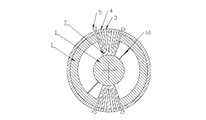
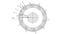
図1-3で示すように、一種のロータリーエンジンであり、シリンダー主体1、ローター2及びシリンダー主体1に設置されているガス入口3、ガス出口4とイグニッション装置5を含む;前記シリンダー主体1とローター2の間に、一組の可動バッフル6が設置され、可動バッフル6がシリンダー主体1の中心を軸に回転できる。
Embodiment 1 As shown in FIG. 1-3, it is a kind of rotary engine, and includes a cylinder main body 1, a
前記イグニッション装置5は、燃料噴射口であってもいいし、又はスパークプラグであっても良い。
The
また、二つの固定バッフル7が設置され、前記の一組の可動バッフル6が二つの内分離刃61及び内分離刃61を固定するディスク62を含み、ディスク62、二つの固定バッフル7、二つの内分離刃61とシリンダー主体1内壁と共に四つの密封キャビティを形成し、この四つの密封キャビティは、それぞれ空気吸入、圧縮、イグニッションと排気という四つの作動ストロークと対応する。
In addition, two fixed baffles 7 are installed, and the set of
また、一つだけの固定バッフル7だけで良い。これで一組の可動バッフル6は、一つの内分離刃61及び内分離刃61を固定するディスク62だけ含み、シリンダー主体1内壁と共に二つの密封キャビティを形成する。
Also, only one fixed baffle 7 is required. Thus, the set of
その中で、固定バッフル(7)とシリンダー主体(1)は一体化構造であり、それに加えて、ガス入口3、ガス出口4とイグニッション装置5が固定バッフル7に設置されている。これで構造が一層簡単で、作用効果も一層良い。
Among them, the fixed baffle (7) and the cylinder main body (1) have an integrated structure, and in addition, a gas inlet 3, a gas outlet 4, and an
前記可動バッフル6のディスク62中心位置に、回転軸63も設置され、回転軸63に単一方向回転機構が設置され、前記単一方向回転機構が、方向が逆である第一単一方向ベアリング11と第二単一方向ベアリング12であり、第二単一方向ベアリング12とローター2の間に、歯車かみ合い伝動機構13が設置され、ローター2を駆動して第二単一方向ベアリング12と逆方向で回転させる;第一単一方向ベアリング11とローター2の間に、ベルト伝動機構14が設置され、ベルト伝動機構2が第一単一方向ベアリング11と同方向で回転させているので、可動バッフル6は、絶えず往複で回転することによって、ローター2を駆動して同じ方向に絶えず回転させる。
A
その上、前記可動バッフル6のディスク62に、起動装置と接続する接続タンク65が設置され、作動を開始するたびに、起動装置は、可動バッフル6を駆動して回転させ、それに加えて、触発感応装置も設置されているので、可動バッフル6が特定の箇所に回転する場合、自動にイグニッションを行い、作業状態に入る。これで正常な起動作業を確保できる。
In addition, a
これを除いて、前記シリンダー主体1及びそのシリンダー主体内の可動バッフル6が複数の組で重ね合わせて配置されることができるので、動力は一層強くなる。
Except for this, the cylinder main body 1 and the
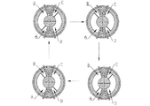
その作動原理は、図4で示すように、可動バッフル6と固定バッフル7がシリンダー主体1をA、B、C、Dという四つのキャビティに分ける。その作動は、空気吸入、圧縮、イグニッションと排気という四つの作動ストロークから構成される。図4の左上隅を第一作動サイクルとして、Aキャビティ空気吸入、Bキャビティ圧縮、Cキャビティイグニッション膨張、Dキャビティ排気とし、可動バッフル6を駆動して時計回りに回転させる;
第一作動サイクルが完了し、第二作動サイクルに入る時、Dキャビティ空気吸入、Aキャビティ圧縮、Bキャビティイグニッション膨張、Cキャビティ排気とし、可動バッフル6を駆動して反時計回りに回転させる;
第二作動サイクルが完了し、第三作動サイクルに入る時、Cキャビティ空気吸入、Dキャビティ圧縮、Aキャビティイグニッション膨張、Bキャビティ排気とし、可動バッフル6を駆動して時計回りに回転させる;
第三作動サイクルが完了し、第四作動サイクルに入る時、Bキャビティ空気吸入、Cキャビティ圧縮、Dキャビティイグニッション膨張、Aキャビティ排気とし、可動バッフル6を駆動して反時計回りに回転させる;
第四作動サイクルが完了する時、第一作動サイクルに入る。
As shown in FIG. 4, the operating principle is that the
When the first operating cycle is completed and the second operating cycle is entered, D cavity air intake, A cavity compression, B cavity ignition expansion, C cavity exhaust, and the
When the second operating cycle is completed and the third operating cycle is entered, C cavity air intake, D cavity compression, A cavity ignition expansion, B cavity exhaust, and the
When the third operating cycle is completed and the fourth operating cycle is entered, B cavity air suction, C cavity compression, D cavity ignition expansion, A cavity exhaust, and the
When the fourth operating cycle is complete, the first operating cycle is entered.
このような四つの小サイクルは、一つの大サイクルを構成し、絶えず可動バッフル6を駆動して往復に回転させ、可動バッフル6上の回転軸63は、第一単一方向ベアリング11を通じて、第二単一方向ベアリング12と共にローター2を駆動して共に絶えず同方向に回転を出力する。
These four small cycles constitute one large cycle, which continuously drives the
これで構造が簡単で、製造が易く、そのうえ、シリンダー内圧縮比を調整しやすく、これで、燃料油の節約効果を達成することができる。 As a result, the structure is simple, the manufacturing is easy, and the compression ratio in the cylinder is easy to adjust, so that the fuel oil saving effect can be achieved.
実施形態二
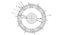
図5-7で示すように、一種のロータリーエンジンであり、シリンダー主体1、ローター2及びシリンダー主体1に設置されているガス入口3、ガス出口4とイグニッション装置5を含む;前記シリンダー主体1とローター2の間に、二組の可動バッフル6が設置されている。
その中で、イグニッション装置5は、燃料噴射口であってもいいし、又はスパークプラグであっても良い。
Among them, the
前記の各組の可動バッフル6が二つの内分離刃61及び内分離刃61を固定するディスク62を含み、前記ローター2がシリンダー主体1の中心に設置され、前記ディスク62がローター2に嵌められている。ディスク62、四つの内分離刃61、シリンダー主体1内壁とローター2外壁は共に四つの密封キャビティを形成し、この四つの密封キャビティは、それぞれ空気吸入、圧縮、イグニッションと排気という四つの作動ストロークと対応する。
Each set of the
前記ディスク62がシリンダー主体1の同じ側に設置されても良く、これで体積が一層小さくなり、構造も一層コンパクトになる。
The
前記ディスク62が両側に設置されても良く、これで組み立が一層便利になる。
The
前記二組の可動バッフル6、ローター2とシリンダー主体1の間に単一方向回転機構が設置されているので、可動バッフル6がシリンダー主体2の中心を軸に回転できると同時に、ローター2を駆動して単一方向で回転させる。
Since the unidirectional rotation mechanism is installed between the two sets of
図9で示すように、前記単一方向回転機構が第一可動歯8及び第二可動歯9を含み、第一可動歯8が直径方向でシリンダー主体1の第一滑り溝16に設置され、第一滑り溝16と滑りはめ合いを行い、第一滑り溝16内部にスプリング15が設置され、第一可動歯8の一端と嵌め合い、第一可動歯8のその他の一端が第一可動歯方向と逆な斜面である。第二可動歯9が直径方向でシリンダー主体1の第二滑り溝17に設置され、第二可動歯17と滑りはめ合いを行い、第二滑り溝17内部にスプリング15が設置され、第二可動歯9の一端と嵌め合い、第二可動歯9のその他の一端が斜面であり、それに加えて、方向が第一可動歯8と逆である。可動バッフル6の内分離刃61が斜面と嵌め合う時、可動歯を押し付けることによって、全部滑り溝に埋め込ませる。可動バッフル6が回転した後、第一可動歯8は、スプリングの弾力の下で回復し、可動バッフル6の内分離刃61が斜面とその他の側の直面と嵌め合う時、可動歯と係合する。これで、単一方向の回転を実現できる。
As shown in FIG. 9, the unidirectional rotating mechanism includes a first movable tooth 8 and a second movable tooth 9, and the first movable tooth 8 is installed in the first sliding
その上、前記単一方向の回転機構は、一組の単一方向ベアリングであっても良い。 Moreover, the unidirectional rotation mechanism may be a set of unidirectional bearings.
前記第一可動歯8と第二可動歯9がシリンダー主体1の外部に設置され、前記第一可動歯8と第二可動歯9との間に外分離刃64が設置され、前記外分離刃64がディスク62に設置され、第一可動歯8と第二可動歯9がシリンダー主体1の外部に設置されているので、修理が一層便利になり、使用寿命も長くなる。
The first movable tooth 8 and the second movable tooth 9 are installed outside the cylinder main body 1, and an
前記第一可動歯8と第二可動歯9が、図8のように、シリンダー主体1の内に設置されても良い。これで構造が一層コンパクトになり、体積が一層小さくなる。 The first movable tooth 8 and the second movable tooth 9 may be installed in the cylinder main body 1 as shown in FIG. This makes the structure more compact and reduces the volume.
シリンダー主体にあるガス入口3、ガス出口4とイグニッション装置5が複数の組が設置され、それに加えて、シリンダー主体外周に均一に密集に分布している。これで構造動力が一層十分になり、効果が一層良くなる。
A plurality of sets of gas inlets 3, gas outlets 4 and
そのうえ、二組の可動バッフル6の間において、間歇伝動を行う間歇伝動機構がを含んでも良い。図16と図17に示すように、間歇伝動機構は、一揃いの不完全な同期化歯車コンポーネントであり、可動バッフル6に設置されている第一不完全な歯車19、ローター2に設置されている大歯車21、連動軸23及び連動軸23に設置されている第二不完全な歯車20及び小歯車22を含む。前記ローター2が回転し、大歯車21と小歯車22のかみ合いを通じて伝動し、連動軸23を駆動して回転させ、連動軸23は第二不完全な歯車20及び第一不完全な歯車19を通じて可動バッフル6を駆動して間歇同期回転させるので、各サイクルにおいて、一組の可動バッフル6が一定の角度で回転した後、その他の一組の可動バッフル6を駆動して同期回転させることによって、二組の可動バッフル6が特定の箇所に来るようにする。これで、毎回のイグニッションが同じ位置で行い、一組のガス入口3、ガス出口4とイグニッション装置5だけで良いことになり、構造が一層簡単になる。
In addition, an intermittent transmission mechanism that performs intermittent transmission between the two sets of
間歇伝動機構もその他の形式であっても良い。例えば、可動バッフル6に同期化カムブロックを設置し、一組の可動バッフル6が一定の角度で回転した後、その他の一組の可動バッフル6と嵌め合い、その他の一組の可動バッフル6を駆動して同期回転させる。
The intermittent transmission mechanism may be of other types. For example, a synchronized cam block is installed on the
それに加えて、起動装置も設置されていて、前記起動装置が起動モーターとエア駆動コイルを含み、前記可動バッフル6のディスク62に、起動モーターと連動接続する接続タンク65が設置され、それに加えて、起動コイルと嵌め合うカムブロックが設置されている。作動を開始するたびに、起動モータはその中の一組の可動バッフル6を駆動して回転させ、起動コイルは、その他の一組の可動バッフル6のカムブロック66と嵌め合い、その他の一組の可動バッフルの回転を抑制する。そのうえ、前記可動バッフル6に触発感応装置も設置されている。自動にイグニッションを行い、順調に作業状態に入ることができる。これで正常な起動作業を確保できる。
In addition, an activation device is also installed, the activation device includes an activation motor and an air driving coil, and a
主な作動原理:
図10に示すように、ガス入口3、ガス出口4とイグニッション装置5がシリンダー主体外周に均一に密集に分布する場合、可動バッフル6は、シリンダー主体1をA1、B1、C1、D1という四つのキャビティに分ける。その作動は、空気吸入、圧縮、イグニッションと排気という四つの作動ストロークから構成される。図12の左上隅を第一作動サイクルとして、A1キャビティ空気吸入、B1キャビティ圧縮、C1キャビティイグニッション膨張、D1キャビティ排気とし、このサイクルの作動により、第一組の可動バッフルと第一可動歯8と係合して固定し、第二組の可動バッフルが第二可動歯と係合し、ローター2を駆動して回転させる;
第一作動サイクルが完了し、第二作動サイクルに入る時、D1キャビティ空気吸入、A1キャビティ圧縮、B1キャビティイグニッション膨張、C1キャビティ排気とし、このサイクルの作動により、第二組の可動バッフルと第一可動歯8と係合して固定し、第一組の可動バッフルが第二可動歯と係合し、ローター2を駆動して共に回転させる;
第二作動サイクルが完了し、第三作動サイクルに入る時、C1キャビティ空気吸入、D1キャビティ圧縮、A1キャビティイグニッション膨張、B1キャビティ排気とし、このサイクルの作動により、第一組の可動バッフルと第一可動歯8と係合して固定し、第二組の可動バッフルが第二可動歯と係合し、ローター2を駆動して共に回転させる;
第三作動サイクルが完了し、第四作動サイクルに入る時、B1キャビティ空気吸入、C1キャビティ圧縮、D1キャビティイグニッション膨張、A1キャビティ排気とし、このサイクルの作動により、第二組の可動バッフルと第一可動歯8と係合して固定し、第一組の可動バッフルが第二可動歯と係合し、ローター2を駆動して共に回転させる。
第四作動サイクルが完了する時、第一作動サイクルに入る。
Main operating principle:
As shown in FIG. 10, when the gas inlet 3, the gas outlet 4 and the
When the first operation cycle is completed and the second operation cycle is entered, D1 cavity air suction, A1 cavity compression, B1 cavity ignition expansion, and C1 cavity exhaust are performed. Engages and locks with the movable teeth 8 and the first set of movable baffles engages with the second movable teeth and drives the
When the second operating cycle is completed and the third operating cycle is entered, C1 cavity air intake, D1 cavity compression, A1 cavity ignition expansion, and B1 cavity exhaust are performed. Engages and locks the movable teeth 8, and the second set of movable baffles engages the second movable teeth and drives the
When the third operation cycle is completed and the fourth operation cycle is entered, B1 cavity air suction, C1 cavity compression, D1 cavity ignition expansion, and A1 cavity exhaust are performed. The movable teeth 8 are engaged and fixed, and the first set of movable baffles are engaged with the second movable teeth, and the
When the fourth operating cycle is complete, the first operating cycle is entered.
このような四つの小サイクルは、一つの大サイクルを構成し、二組の可動バッフル6が順番に循環し、ローター2を駆動して共に回転させる。ローター2は、出力軸9を駆動して共に絶えず同方向に回転を出力させる。
可動バッフル1で、シリンダー主体1を幾つかのキャビティに分けてサイクル作動を行うと、構造が簡単で、製造が易いと同時に、シリンダー内圧縮比を調整しやすくなり、これで、燃料油の節約効果を達成することができる。そのうえ、出力動力が強くなる。
Such four small cycles constitute one large cycle, and two sets of
When the cylinder main body 1 is divided into several cavities and operated with a movable baffle 1, the structure is simple and easy to manufacture, and at the same time it is easy to adjust the compression ratio in the cylinder, which saves fuel oil. The effect can be achieved. In addition, the output power increases.
実施形態三
図11-13で示すように、一種のロータリーエンジンであり、シリンダー主体1、ローター2及びシリンダー主体1に設置されているガス入口3、ガス出口4とイグニッション装置5を含む;前記シリンダー主体1が二つ設置され、即ち、第一シリンダー主体と第二シリンダー主体となり、各シリンダー主体1に、二組の可動バッフル6が設置されている。それに加えて、第一シリンダー主体内の可動バッフル6は、第二シリンダー主体内の可動バッフル6と接続する。
Embodiment 3 As shown in FIG. 11-13, it is a kind of rotary engine, and includes a cylinder main body 1, a
前記の各組の可動バッフル6が一つの内分離刃61及び内分離刃61を固定するディスク62を含み、前記ローター2がシリンダー主体1の中心に設置され、前記ディスク62がローター2に嵌められている。
Each set of the
各シリンダー主体1内部は、ディスク62、内分離刃61、シリンダー主体1内壁とローター2外壁を通じて、二つの密封キャビティを形成し、二つのシリンダー主体は合計四つの密封キャビティを形成し、この四つの密封キャビティは、それぞれ空気吸入、圧縮、イグニッションと排気という四つの作動ストロークと対応する。
Each cylinder main body 1 forms two sealed cavities through the
前記可動バッフル6、ローター2とシリンダー主体1の間に単一方向回転機構が設置されているので、可動バッフル6がシリンダー主体2の中心を軸に回転できると同時に、ローター2を駆動して単一方向で回転させる。
Since a unidirectional rotation mechanism is installed between the
それに加えて、起動装置も設置されていて、前記起動装置が起動モーターとエア駆動コイルを含み、
前記可動バッフル6のディスク62に、起動モーターと連動接続する接続タンク65が設置され、それに加えて、起動コイルと嵌め合うカムブロックが設置されている。作動を開始するたびに、起動モータはその中の一組の可動バッフル6を駆動して回転させ、起動コイルは、その他の一組の可動バッフル6のカムブロック66と嵌め合い、その他の一組の可動バッフルの回転を抑制する。そのうえ、前記可動バッフル6に触発感応装置も設置されている。自動にイグニッションを行い、順調に作業状態に入ることができる。これで正常な起動作業を確保できる。
In addition, an activation device is also installed, the activation device including an activation motor and an air drive coil,
On the
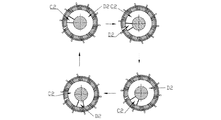
主な作動原理は、図14と図15に示すように、図14が第一シリンダー主体であり、可動バッフル6とローター2で、A2、B2という二つの密封キャビティに分けられ、図15が第二シリンダー主体であり、可動バッフル6とローター2で、C2、D2という二つの密封キャビティに分けられ、それに加えて、第一シリンダー主体内の可動バッフル6は、第二シリンダー主体内の可動バッフル6と接続するので、その可動バッフル6は、同期化回転を行う。
As shown in FIGS. 14 and 15, the main operating principle is that the main body of the first cylinder is shown in FIG. 14, and the
その作動は、空気吸入、圧縮、イグニッションと排気という四つの作動ストロークから構成される。図14及び図15の左上隅を第一作動サイクルとして、A2キャビティ空気吸入、B2キャビティ圧縮、C2キャビティイグニッション膨張、D2キャビティ排気とし、このサイクルの作動により、第一組の可動バッフルを固定し、第二組の可動バッフルがローター2を駆動して共に回転させる;
第一作動サイクルが完了し、第二作動サイクルに入る時、D2キャビティ空気吸入、A2キャビティ圧縮、B2キャビティイグニッション膨張、C2キャビティ排気とし、このサイクルの作動により、第二組の可動バッフルを固定し、第一組の可動バッフルがローター2を駆動して共に回転させる;
第二作動サイクルが完了し、第三作動サイクルに入る時、C2キャビティ空気吸入、D2キャビティ圧縮、A2キャビティイグニッション膨張、B2キャビティ排気とし、このサイクルの作動により、第一組の可動バッフルを固定し、第二組の可動バッフルがローター2を駆動して共に回転させる;
第三作動サイクルが完了し、第四作動サイクルに入る時、B2キャビティ空気吸入、C2キャビティ圧縮、D2キャビティイグニッション膨張、A2キャビティ排気とし、このサイクルの作動により、第二組の可動バッフルを固定し、第一組の可動バッフルがローター2を駆動して共に回転させる;
第四作動サイクルが完了する時、第一作動サイクルに入る。
The operation consists of four operating strokes: air intake, compression, ignition and exhaust. The upper left corner of FIG. 14 and FIG. 15 is the first operating cycle, A2 cavity air suction, B2 cavity compression, C2 cavity ignition expansion, D2 cavity exhaust, and by this cycle operation, the first set of movable baffles is fixed, A second set of movable baffles drives
When the first operation cycle is completed and the second operation cycle is entered, D2 cavity air suction, A2 cavity compression, B2 cavity ignition expansion, and C2 cavity exhaust are performed, and the second set of movable baffles is fixed by this cycle operation. A first set of movable baffles drives
When the second operation cycle is completed and the third operation cycle is entered, C2 cavity air suction, D2 cavity compression, A2 cavity ignition expansion, and B2 cavity exhaust are performed, and the first set of movable baffles is fixed by the operation of this cycle. A second set of movable baffles drives
When the third operation cycle is completed and the fourth operation cycle is entered, B2 cavity air suction, C2 cavity compression, D2 cavity ignition expansion, and A2 cavity exhaust are performed, and the second set of movable baffles is fixed by this cycle operation. A first set of movable baffles drives
When the fourth operating cycle is complete, the first operating cycle is entered.
このような四つの小サイクルは、一つの大サイクルを構成し、二組の可動バッフル6が順番に循環し、ローター2を駆動して共に回転させる。ローター2は、出力軸9を駆動して共に絶えず同方向に回転を出力させる。
Such four small cycles constitute one large cycle, and two sets of
可動バッフル1で、シリンダー主体1を幾つかの密封キャビティに分けて重ね合わせて、サイクル作動を行うと、構造が簡単で、製造が易いと同時に、シリンダー内圧縮比を調整しやすくなり、これで、燃料油の節約効果を達成することができる。そのうえ、出力動力が強くなる。 When the cylinder body 1 is divided into several sealed cavities and overlapped with the movable baffle 1 and cycled, the structure is simple and easy to manufacture, and at the same time, the compression ratio in the cylinder is easy to adjust. , Fuel oil saving effect can be achieved. In addition, the output power increases.
実施形態四
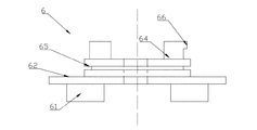
更に、図18に示すように、一種のコンプレッサーであり、圧縮コンポーネント18とローターエンジンを含み、前記圧縮コンポーネントが圧縮シリンダーと圧縮セパレータを含み、
その中のローターエンジンが図1-17で示すように,シリンダー主体1、ローター2及びシリンダー主体1に設置されているガス入口3、ガス出口4とイグニッション装置5を含む;前記シリンダー主体1内に、少なくとも一組の可動バッフル6が設置され、シリンダー体1内壁と密封して嵌め合うことによって、少なくとも二つの密封キャビティを形成する;可動バッフル6がシリンダー主体1の中心を軸に回転できる;前記可動バッフル6が圧縮セパレータと接続し、動バッフル6が圧縮セパレータを駆動して回転させることができる。これでコンプレッサーの機能を実現でき、構造が簡単で、製造が易くなる。
Embodiment 4 Furthermore, as shown in FIG. 18, it is a kind of compressor, including a
As shown in FIG. 1-17, the rotor engine therein includes a cylinder main body 1, a
それに加えて、揚水ポンプ、真空ポンプ及びファン等の類似構造に使用しても良い。 In addition, you may use for similar structures, such as a pump, a vacuum pump, and a fan.
実施形態は、発明の制限と見なしてはいけない。但し、本発明の精神に基づいて実施された如何なる改善は、本発明の保護範囲に属する。 The embodiments should not be regarded as limitations of the invention. However, any improvements made based on the spirit of the present invention belong to the protection scope of the present invention.
Claims (9)
[1]前記シリンダー主体(1)内に、少なくとも一組の可動バッフル(6)が設置され、前記シリンダー本体(1)の壁と密封で嵌め合うことによって、少なくとも二つの密封キャビティを形成し、
[2]前記可動バッフル(6)が、前記シリンダー主体(1)の中心を軸に回転し、
[3]前記可動バッフル(6)と前記ローター(2)との間に、単一方向の回転機構が設置され、前記ローター(2)を駆動して単一方向で回転させるロータリーエンジンであって、
前記シリンダー主体(1)内に、二組の可動バッフル(6)が設置され、当該二組の可動バッフル(6)がシリンダー主体(1)中心を軸に回って単一方向に同方向で回転し、
[1]前記単一方向の回転機構が、第一可動歯(8)及び第二可動歯(9)を含み、前記シリンダー主体(1)の直径方向に第一可動歯(8)取付用第一滑り溝(16)が設置され、第一可動歯(8)が第一滑り溝(16)と滑りはめ合いを行い、第一可動歯(8)の一端で弾性戻り部品と接続し、その他の一端が斜面であり、
[2]前記ローター(2)の直径方向に第二可動歯(9)取付用第二滑り溝(17)が設置され、その中で、第二可動歯(9)が第二滑り溝(17)と滑りはめ合いを行い、第二可動歯(9)の一端で弾性戻り部品と接続し、その他の一端が第一可動歯(8)方向と逆な斜面であり、
前記二組の可動バッフル(6)の間に、間歇伝動を行う間歇伝動機構があり、
前記間歇伝動機構は、一揃いの不完全な同期化歯車コンポーネントであり、前記二組の可動バッフル(6)に設置されている第一不完全な歯車(19)、前記ローター(2)に設置されている大歯車(21)、連動軸(23)及び連動軸(23)に設置されている第二不完全な歯車(20)、及び小歯車(22)を含み、前記ローター(2)が回転すると、前記大歯車(21)が回転し、前記大歯車(21)が回転すると前記大歯車(21)と前記小歯車(22)のかみ合いを通じて前記小歯車(22)が回転し、前記小歯車(22)が回転すると前記小歯車(22)と連動する前記連動軸(23)が回転し、前記連動軸(23)が回転することにより、第二不完全な歯車(20)が回転し、第二不完全な歯車(20)が回転することにより第一不完全な歯車(19)が回転駆動されることを通じて、前記二組の可動バッフル(6)を間歇同期回転する、
ロータリーエンジン。 A cylinder main body (1), a rotor (2) , a gas inlet (3) installed in the cylinder main body (1), a gas outlet (4) and an ignition device (5);
[1] to the cylinder main body (1) within at least one set of movable baffle (6) is installed, by mate sealingly with the cylinder wall of the body (1), to form at least two sealing cavities,
[2] The movable baffle (6) is to rotate the center of the cylinder main body (1) in the axial,
[3] between the said rotor and movable baffle (6) (2), a unidirectional rotation mechanism is placed, a rotary engine that rotates in a single direction by driving the rotor (2) ,
Two sets of movable baffles (6) are installed in the cylinder main body (1), and the two sets of movable baffles (6) rotate around the center of the cylinder main body (1) in the same direction in a single direction. And
[1] the unidirectional rotation mechanism comprises a first movable tooth (8) and a second movable tooth (9), the first movable tooth (8) in the radial direction of the cylinder main body (1) first mounting One sliding groove (16) is installed, the first movable tooth (8) is slip-fit with the first sliding groove (16), and is connected to the elastic return part at one end of the first movable tooth (8), etc. one end of the slope der of is,
[2] A second sliding groove (17) for mounting the second movable tooth (9) is installed in the diameter direction of the rotor (2), and the second movable tooth (9) is the second sliding groove (17 ) and each other to perform sliding fit, connected to the second end elastic return parts of movable tooth (9), the other end first movable tooth (8) up direction opposite slope der,
Between the two sets of movable baffles (6), there is an intermittent transmission mechanism that performs intermittent transmission ,
The intermittent transmission mechanism is imperfect synchronization gear components of one set, the two sets of the first incomplete gear (19) installed in the movable baffle (6), installed the in the rotor (2) large gear being (21), the second incomplete gear installed in the interlocking shaft (23) and the interlocking shaft (23) (20), and only contains small gear (22), said rotor (2) Rotates the large gear (21), and when the large gear (21) rotates, the small gear (22) rotates through the meshing of the large gear (21) and the small gear (22), When the small gear (22) rotates, the interlocking shaft (23) interlocked with the small gear (22) rotates, and the interlocking shaft (23) rotates, thereby rotating the second incomplete gear (20). The first imperfect gear (19) is rotated by the rotation of the second imperfect gear (20). Two sets of movable baffles (6) rotates intermittently synchronously,
Rotary engine.
Applications Claiming Priority (3)
| Application Number | Priority Date | Filing Date | Title |
|---|---|---|---|
| CN201310569757.8A CN103615311B (en) | 2013-11-13 | 2013-11-13 | A kind of rotary engine |
| CN201310569757.8 | 2013-11-13 | ||
| PCT/CN2014/085490 WO2015070659A1 (en) | 2013-11-13 | 2014-08-29 | Rotary engine |
Publications (2)
| Publication Number | Publication Date |
|---|---|
| JP2016540922A JP2016540922A (en) | 2016-12-28 |
| JP6174259B2 true JP6174259B2 (en) | 2017-08-09 |
Family
ID=50166025
Family Applications (1)
| Application Number | Title | Priority Date | Filing Date |
|---|---|---|---|
| JP2016530166A Expired - Fee Related JP6174259B2 (en) | 2013-11-13 | 2014-08-29 | A kind of rotary engine |
Country Status (6)
| Country | Link |
|---|---|
| US (1) | US9777624B2 (en) |
| EP (1) | EP3070289B1 (en) |
| JP (1) | JP6174259B2 (en) |
| KR (1) | KR101696163B1 (en) |
| CN (1) | CN103615311B (en) |
| WO (1) | WO2015070659A1 (en) |
Families Citing this family (10)
| Publication number | Priority date | Publication date | Assignee | Title |
|---|---|---|---|---|
| CN103615311B (en) | 2013-11-13 | 2016-06-29 | 何时立 | A kind of rotary engine |
| CN105173553A (en) * | 2015-08-28 | 2015-12-23 | 重庆市腾瀚工贸有限公司 | Intermittent transportation device for steering knuckles |
| CN105626531A (en) * | 2016-01-29 | 2016-06-01 | 赵文瑞 | Dry rotary vane vacuum pump |
| CN106194430A (en) * | 2016-09-30 | 2016-12-07 | 淄博衡动机械制造有限公司 | Collision explosion motor |
| CN106499503B (en) * | 2016-11-16 | 2019-02-19 | 山东理工大学 | A kind of variable compression ratio rotary engine of reciprocal circular motion |
| CN107165034A (en) * | 2017-07-18 | 2017-09-15 | 湖南煜欣轨道装备科技工程有限公司 | A kind of milling machine |
| CN109538478A (en) * | 2018-11-27 | 2019-03-29 | 王廷华 | A kind of compressor |
| CN110067645A (en) * | 2019-04-26 | 2019-07-30 | 浙江大学 | A kind of New Ring-like Type engine |
| CN112140288B (en) * | 2020-09-24 | 2021-07-30 | 湖南省新化县鑫星电子陶瓷有限责任公司 | High-reliability mechanical automatic ceramic plate dry pressing device |
| CN113399150B (en) * | 2021-05-20 | 2023-07-25 | 青岛固德复材科技有限公司 | Paint spraying device for safety helmet |
Family Cites Families (20)
| Publication number | Priority date | Publication date | Assignee | Title |
|---|---|---|---|---|
| JPS4818615B1 (en) | 1968-08-26 | 1973-06-07 | ||
| FR2116650A5 (en) * | 1970-12-02 | 1972-07-21 | Iel Marc | |
| DE2320353A1 (en) | 1973-04-21 | 1974-11-07 | Max Schueler | CENTER-AXIS REVOLVING PISTON POWER MACHINE |
| JPS5535114A (en) * | 1978-08-31 | 1980-03-12 | Koichi Tanaka | Coaxial rotating piston engine |
| DE3123121A1 (en) | 1981-06-11 | 1982-12-30 | Werner 5138 Heinsberg Hustert | Rotary internal combustion engine |
| CN1055578A (en) * | 1990-04-09 | 1991-10-23 | 覃勇 | High-speed rotary engine |
| US5484272A (en) | 1994-06-20 | 1996-01-16 | Horn; Clarence G. | Rotary internal combustion engine |
| CN1156213A (en) * | 1996-01-30 | 1997-08-06 | 赵可军 | Rotary wheel type fluid function changing device |
| CN1186154A (en) * | 1996-10-26 | 1998-07-01 | 李国富 | Engine with rotor having convex end |
| KR100261911B1 (en) * | 1998-04-27 | 2000-07-15 | 김은규 | Rotary piston comppessor device |
| JP2001289053A (en) * | 2000-04-03 | 2001-10-19 | Teruo Ataya | Hybrid corresponding rotary engine |
| JP4140017B1 (en) * | 2007-06-05 | 2008-08-27 | 樹伸 大森 | Rotating piston engine correlation crank |
| CN201092883Y (en) * | 2007-08-25 | 2008-07-30 | 陈昌全 | Rotary plate-type internal combustion engine |
| CN101397934A (en) * | 2008-03-19 | 2009-04-01 | 孙光斌 | Rotary piston combustion engine without counter force having pulling and inserting type baffle |
| CN101970800B (en) * | 2008-05-26 | 2012-08-29 | 张振明 | A dual-rotor engine |
| CN101639009A (en) * | 2009-08-31 | 2010-02-03 | 李乐 | Rotary oscillation piston engine |
| CN102562283B (en) * | 2010-12-20 | 2015-03-11 | 苏承寰 | Internal combustion engine with double rotor pistons |
| CN103032158B (en) * | 2012-12-05 | 2015-04-01 | 汪辉 | Circular cylinder engine |
| CN203515795U (en) * | 2013-11-13 | 2014-04-02 | 何时立 | Rotor engine |
| CN103615311B (en) * | 2013-11-13 | 2016-06-29 | 何时立 | A kind of rotary engine |
-
2013
- 2013-11-13 CN CN201310569757.8A patent/CN103615311B/en active Active
-
2014
- 2014-08-29 JP JP2016530166A patent/JP6174259B2/en not_active Expired - Fee Related
- 2014-08-29 US US15/036,764 patent/US9777624B2/en active Active
- 2014-08-29 EP EP14862919.9A patent/EP3070289B1/en active Active
- 2014-08-29 KR KR1020167014044A patent/KR101696163B1/en active IP Right Grant
- 2014-08-29 WO PCT/CN2014/085490 patent/WO2015070659A1/en active Application Filing
Also Published As
| Publication number | Publication date |
|---|---|
| EP3070289A1 (en) | 2016-09-21 |
| CN103615311A (en) | 2014-03-05 |
| KR101696163B1 (en) | 2017-01-23 |
| EP3070289A4 (en) | 2017-06-07 |
| US9777624B2 (en) | 2017-10-03 |
| EP3070289B1 (en) | 2020-08-26 |
| WO2015070659A1 (en) | 2015-05-21 |
| US20160290222A1 (en) | 2016-10-06 |
| CN103615311B (en) | 2016-06-29 |
| KR20160065218A (en) | 2016-06-08 |
| JP2016540922A (en) | 2016-12-28 |
Similar Documents
| Publication | Publication Date | Title |
|---|---|---|
| JP6174259B2 (en) | A kind of rotary engine | |
| EA006410B1 (en) | Internal combustion engine and method | |
| WO2013152730A1 (en) | Rotor compressor, rotor engine and rotor turbine | |
| CN203515795U (en) | Rotor engine | |
| CN112253310A (en) | Diesel rotor engine | |
| CN113374573B (en) | Circumferential flow turbine | |
| RU2538990C1 (en) | Rotor-piston internal combustion engine | |
| WO2009103210A1 (en) | Ratchet-wheel type rotary engine | |
| CA2496051C (en) | Positive displacement rotary device and method of use | |
| CN107514309B (en) | Reciprocating rotor piston for engine | |
| RU154633U1 (en) | ROTARY DEVICE | |
| CN216198457U (en) | Stepping 3-cylinder dual-rotor internal combustion engine | |
| CN106285926B (en) | Axial variable rotor engine | |
| JP2013234647A (en) | Rotation type internal combustion engine in cylinder | |
| CN113803157A (en) | Double-rotor engine | |
| TWI441980B (en) | Rotary engine | |
| JP3204391U (en) | Rotary engine | |
| CN100460640C (en) | Rotor type internal-combustion engine in three strokes | |
| RU2190106C2 (en) | Rotary engine (versions) | |
| IE20150358A1 (en) | Fluid transfer device | |
| CN2733005Y (en) | Rotary piston internal combustion engine | |
| CN1164610A (en) | Principle of rotor explosive motor | |
| US3550564A (en) | Rotary internal combustion engine | |
| RU2399769C1 (en) | Laminar mill machine | |
| JP6107800B2 (en) | Apex seal structure of rotary piston engine |
Legal Events
| Date | Code | Title | Description |
|---|---|---|---|
| A521 | Request for written amendment filed |
Free format text: JAPANESE INTERMEDIATE CODE: A523 Effective date: 20160929 |
|
| A975 | Report on accelerated examination |
Free format text: JAPANESE INTERMEDIATE CODE: A971005 Effective date: 20161110 |
|
| A131 | Notification of reasons for refusal |
Free format text: JAPANESE INTERMEDIATE CODE: A131 Effective date: 20161206 |
|
| A521 | Request for written amendment filed |
Free format text: JAPANESE INTERMEDIATE CODE: A523 Effective date: 20170303 |
|
| A131 | Notification of reasons for refusal |
Free format text: JAPANESE INTERMEDIATE CODE: A131 Effective date: 20170411 |
|
| A521 | Request for written amendment filed |
Free format text: JAPANESE INTERMEDIATE CODE: A523 Effective date: 20170518 |
|
| TRDD | Decision of grant or rejection written | ||
| A01 | Written decision to grant a patent or to grant a registration (utility model) |
Free format text: JAPANESE INTERMEDIATE CODE: A01 Effective date: 20170620 |
|
| A61 | First payment of annual fees (during grant procedure) |
Free format text: JAPANESE INTERMEDIATE CODE: A61 Effective date: 20170705 |
|
| R150 | Certificate of patent or registration of utility model |
Ref document number: 6174259 Country of ref document: JP Free format text: JAPANESE INTERMEDIATE CODE: R150 |
|
| R250 | Receipt of annual fees |
Free format text: JAPANESE INTERMEDIATE CODE: R250 |
|
| R250 | Receipt of annual fees |
Free format text: JAPANESE INTERMEDIATE CODE: R250 |
|
| R250 | Receipt of annual fees |
Free format text: JAPANESE INTERMEDIATE CODE: R250 |
|
| LAPS | Cancellation because of no payment of annual fees |