JP6165445B2 - Alarm system, alarm device and repeater - Google Patents
Alarm system, alarm device and repeater Download PDFInfo
- Publication number
- JP6165445B2 JP6165445B2 JP2013003510A JP2013003510A JP6165445B2 JP 6165445 B2 JP6165445 B2 JP 6165445B2 JP 2013003510 A JP2013003510 A JP 2013003510A JP 2013003510 A JP2013003510 A JP 2013003510A JP 6165445 B2 JP6165445 B2 JP 6165445B2
- Authority
- JP
- Japan
- Prior art keywords
- fire
- alarm device
- alarm
- synchronization
- signal
- Prior art date
- Legal status (The legal status is an assumption and is not a legal conclusion. Google has not performed a legal analysis and makes no representation as to the accuracy of the status listed.)
- Active
Links
Images


Description
この発明は、火災等の非常事態発生時に避難を促す警報システムおよび警報装置に関し、特に光によって警報を発する警報システムおよび警報装置に関する。 The present invention relates to an alarm system and an alarm device that prompts evacuation when an emergency such as a fire occurs, and more particularly to an alarm system and an alarm device that issue an alarm by light.
従来、自動火災報知設備は、所定の間隔で配設した警報用音響装置を所定の音量で鳴動させ、あるいは、連動動作させた非常放送設備によって音声メッセージを流し、火災発生を警報して避難を促すものであった。 Conventionally, automatic fire alarm equipment has been evacuated by sounding an alarm sound device arranged at a predetermined interval at a predetermined volume, or by playing an audio message through an emergency broadcasting facility that has been operated in conjunction, warning the occurrence of a fire. It was something to encourage.
しかしながら、火災等の非常事態発生時に避難するべき人に聴覚障害があるような場合、光等の聴覚以外の感覚に働きかけて非常事態を知らせる警報装置の普及が望まれている。そして、強烈な閃光を発するストロボ(登録商標)に代表されるエレクトロニック・フラッシュや、大光量のLEDランプ、等を光源に用い、フラッシュ光を発する警報装置が実用化されている。 However, in the case where a person who should evacuate in the event of an emergency such as a fire has a hearing impairment, it is desired to spread an alarm device that works on a sense other than hearing such as light to notify the emergency. An alarm device that emits flash light using an electronic flash typified by a strobe (registered trademark) that emits intense flash light, a large-intensity LED lamp, or the like as a light source has been put into practical use.
従来、平常時は消灯し、火災等の非常事態発生時にフラッシュ光を発する警報装置は、その発光周期を各警報装置自体で制御するものであった。そのような警報装置を、自動火災報知設備の警報用音響装置のように所定の間隔で多数設置し、火災発生時に同時に作動させると、多数の警報装置それぞれがバラバラのタイミングで発光する。このような人工的な強い光刺激は、人に光刺激性癲癇などの光過敏性発作を引き起こす場合があることが知られている(例えば、平成9年12月16日に某民間テレビ放送局が放送した、強い光刺激シーンのあるテレビアニメの視聴者が光過敏性発作などを起こした事件は大きく報道され、周知である)。 Conventionally, an alarm device that is normally turned off and emits flash light in the event of an emergency such as a fire has been controlled by each alarm device itself. When a large number of such alarm devices are installed at predetermined intervals like the alarm sound device of the automatic fire alarm facility and are activated at the same time when a fire occurs, each of the many alarm devices emits light at different timings. It is known that such artificial strong light stimulation may cause photosensitivity seizures such as light-stimulating epilepsy in humans (for example, a private television broadcasting station on December 16, 1997). The case that a viewer of a TV animation with a strong light stimulation scene broadcasted by the company caused a photosensitivity attack was widely reported and well-known.
この発明は、光過敏性発作を引き起こすことなく、聴覚障害がある人にも火災等の非常事態発生を知らせて避難を促すことができる、フラッシュ光を用いた警報システムおよび警報装置を得ることを目的とする。 It is an object of the present invention to provide an alarm system and an alarm device using a flashlight that can notify a person with hearing impairment to the occurrence of an emergency such as a fire and prompt evacuation without causing a photosensitivity attack. Objective.
(1)この発明の警報システムは、火災発生時に火災信号を送出する火災受信機と、前記火災信号に基づいて共通の所定周期でフラッシュ発光する発光手段を有する複数の警報装置と、を具備する警報システムにおいて、前記警報装置は、前記火災信号を受信してから計時を開始して前記所定周期で初期化される同期タイマと、該同期タイマの計時値が初期値と異なる所定値となったときに前記発光手段をフラッシュ発光させる発光制御手段と、を有し、複数が避難経路毎にグループ編成され、前記火災信号を受信したグループに属する前記警報装置は、同じタイミングでフラッシュ発光を繰り返すことを特徴とする。
(1) warning system of the present invention, comprises a fire control panel for sending a fire signal to the event of a fire, and a plurality of alarm device having a light emitting means for flash at a common predetermined period on the basis of the fire signal In the alarm system, the alarm device starts counting time after receiving the fire signal and is initialized at the predetermined period, and the time value of the synchronous timer becomes a predetermined value different from the initial value. And a light emission control means for causing the light emission means to emit flash light. A plurality of the light emission control means are grouped for each evacuation route, and the alarm devices belonging to the group receiving the fire signal repeat flash light emission at the same timing. It is characterized by that.
(2)また、この発明の警報システムは、(1)において、前記火災受信機と前記警報装置との間に介在して、前記所定周期の整数倍の周期で同期補正信号を前記警報装置に送出する同期補正手段をさらに備え、前記同期補正信号を受信した前記警報装置は、少なくとも前記グループ毎に同期タイマの脱調を補正することを特徴とする。
(2) In the alarm system of the present invention, in (1), a synchronization correction signal is transmitted to the alarm device at a cycle that is an integral multiple of the predetermined cycle, interposed between the fire receiver and the alarm device. further comprising a synchronization correction means for sending, the synchronization correction signal the alarm device receiving is characterized by correcting at least step-out of the synchronization timer for each of the groups.
(3)また、この発明の警報装置は、火災受信機からの火災信号に基づいて所定周期でフラッシュ発光する発光手段を有する警報装置において、前記警報装置は、前記火災信号を受信してから計時を開始して前記所定周期で初期化される同期タイマと、該同期タイマの計時値が初期値と異なる所定値となったときに前記発光手段をフラッシュ発光させる発光制御手段と、を有し、複数が避難経路毎にグループ編成され、前記火災信号を受信したグループに属する前記警報装置は、同じタイミングでフラッシュ発光を繰り返すことを特徴とする。
(3) Further, the alarm device of the present invention is an alarm device having a light emitting means for flashing light at a predetermined cycle based on a fire signal from a fire receiver, wherein the alarm device measures time after receiving the fire signal. And a synchronization timer that is initialized at the predetermined period, and a light emission control means that causes the light emission means to flash when the time value of the synchronization timer reaches a predetermined value different from the initial value, A plurality are grouped for each evacuation route, and the alarm devices belonging to the group that has received the fire signal repeat flash emission at the same timing.
(4)また、この発明の警報装置は、(3)において、同期補正信号を受信することによって前記同期タイマの脱調を補正する制御手段をさらに有することを特徴とする。
(4) In addition, the alarm device of the present invention is characterized in that, in (3), the alarm device further includes control means for correcting a step-out of the synchronization timer by receiving a synchronization correction signal .
(5)また、この発明の中継器は、火災発生時に火災信号を送出する火災受信機と、避難経路毎にグループ編成され、前記火災信号に基づいて所定周期で初期化される同期タイマと、該同期タイマの計時値が初期値と異なる所定値となったときに発光手段をフラッシュ発光させる発光制御手段と、同期補正信号を受信すると前記同期タイマの脱調を補正する制御手段とを有し、する警報装置との間に介在する中継器であって、前記中継器は、前記所定周期の整数倍の周期で同期補正信号を前記警報装置に送出する同期補正手段を備え、少なくとも前記グループ毎に前記同期補正信号を受信した前記警報装置の同期タイマの脱調を補正することを特徴とする。
(5) Further, the repeater of the present invention includes a fire receiver that sends out a fire signal when a fire occurs, a synchronization timer that is grouped for each evacuation route and is initialized at a predetermined period based on the fire signal, A light emission control means for flashing the light emission means when the time value of the synchronization timer becomes a predetermined value different from the initial value; and a control means for correcting the step-out of the synchronization timer when a synchronization correction signal is received. A relay device interposed between the alarm device and the alarm device, the relay device comprising synchronization correction means for sending a synchronization correction signal to the alarm device at a cycle that is an integral multiple of the predetermined cycle, and at least for each group The step-out of the synchronization timer of the alarm device that has received the synchronization correction signal is corrected .
複数の警報装置が同期して同じタイミングでフラッシュ発光し、バラバラのタイミングでフラッシュ発光しないので、光過敏性発作を引き起こすことなく、聴覚障害がある人にも火災発生を知らせて避難を促すことができるという効果を奏する。また、フラッシュ発光に伴う電源変動が発生しても、誤ってフラッシュ発光させないという効果を奏する。 Because multiple alarm devices synchronize to flash at the same timing and do not flash at different timings, people with hearing impairments can be notified of fires and evacuated without causing photosensitivity attacks There is an effect that can be done. In addition, there is an effect that even if the power supply fluctuation accompanying the flash emission occurs, the flash emission is not erroneously performed.
[実施の形態1]
本発明の実施の形態1について、図1乃至3に基づいて説明する。
まず、図1を参照して本実施の形態に係る警報システムの構成を説明する。
[Embodiment 1]
First, the configuration of the alarm system according to the present embodiment will be described with reference to FIG.
火災感知器2は、火災発生時に火災を感知する火災感知手段である。
The
火災感知器2と電路Lsを介して接続された火災受信機1は、火災感知器2からの火災感知信号Dを受信し、この火災感知信号Dに基づいて火災判断を行い、火災と判断したときに、火災受信機1の備わる表示灯や音響装置等によって火災表示および火災音響警報を行う周知の火災受信機である。
The
火災感知器2と火災受信機1とを接続する電路Lsは、図示したように火災感知器2の系統毎に個別の電路で接続するP型システムであっても良いし、多重伝送によって共通の電路で接続するR型システムであっても良い。火災受信機1が火災と判断したときは、電路Lfを介して後述する警報装置4に向けて火災信号Fを送出する。なお、後述する警報装置4への電力の供給は火災受信機1から行い、電力供給には図示したように火災信号Fを伝達する電路Lfを共用しても良いし、別途専用の電源線(図示せず)を設けても良い。前者の場合、火災受信機1から後述する警報装置4に電力を供給する電源線でもある電路Lfに送出する火災信号Fを電力源として用いる。
The electric circuit Ls that connects the
警報装置4は、火災受信機1から送出される火災信号Fに基づいてフラッシュ発光するものである。警報装置4は、複数が避難経路毎にグループ編成され、間隔を空けて並列接続されて配設され、便宜上、それぞれを警報装置4−1〜4−n(nは自然数、n=1,2,3,・・・)と火災受信機1側から順に番号を付して区別する。
The
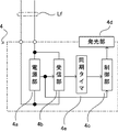
次に、図2を参照して本実施の形態に係る警報装置4の構成を説明する。
Next, the configuration of the
警報装置4は、電路Lfを介して火災受信機1からの火災信号Fを受信する火災信号受信手段である受信部4bを有する。
The
また、警報装置4は、受信部4bが火災受信機1からの火災信号Fを受信したときに計時を開始する計時手段である同期タイマ4eを有する。同期タイマ4eはすべての警報装置4−1〜4−nに共通である所定周期T毎に初期化され、初期化後は再び計時を継続する。また、同期タイマ4eの計時値が予め定めた初期値と異なる所定値、すなわち閾値に達したとき、後述する制御手段である制御部4cにフラッシュ発光のタイミングを指示する。
Further, the
また、このフラッシュ発光のタイミングの指示を受けて、後述する発光部4dをフラッシュ発光させる発光制御手段である制御部4cを有する。
In addition, it has a
また、警報装置4は、火災受信機1から電力の供給を受けて警報装置の各部に電力を供給する電源部4aを有する。
In addition, the
発光部4dには、強烈な閃光を発するストロボ(登録商標)に代表されるエレクトロニック・フラッシュ、あるいは、大光量のLEDランプを発光手段として用いることができる。なお、発光部4dに用いる発光手段はこれらに限定されるものではなく、光で警報するに足る一定以上の光量を発することができ、断続制御できる可視光の光源であれば良い。
As the
発光部4dは、図示したように制御部4cを介して電力の供給を受けても良いし、電源部4aから直接電力の供給を受け(図示せず)、発光部4dを発光させるためのトリガ信号を制御部4cから受けるようにしても良い。後者の構成は、発光手段にエレクトロニック・フラッシュを用い、これに電源部4aから放電開始に至らない高電圧を予め印加しておき、このときのエレクトロニック・フラッシュを放電させて発光を開始させるトリガ電極に制御部4cからトリガ信号を送出する用途に適している。
The
次に、更に図3を参照して、本実施の形態に係る警報システムの動作を説明する。 Next, the operation of the alarm system according to the present embodiment will be described with reference to FIG.
火災感知器2は、火災を感知すると電路Lsを介して接続された火災受信機1へ火災感知信号Dを送出する。この火災感知信号Dを受信した火災受信機1は、火災受信機1に備わる蓄積機能等の火災判断手段によって火災と判断すると、電路Lfを介して接続された警報装置4−1〜nへ火災信号Fを送出する。
When the
警報装置4は、火災受信機1からの火災信号Fを受信部4bが受信すると、同期タイマ4eが計時を開始し、所定周期T毎に初期化し、初期化後は同期タイマ4eの初期値より再び計時を行う動作を繰り返す。この動作は、警報装置4が火災信号Fを受信している間に継続され、火災信号Fを受信しなくなると同期タイマ4eは計時を停止し、初期化される。そして、同期タイマ4eの計時値が予め定めた所定値、すなわち閾値に達すると、制御部4cに対してフラッシュ発光を指令し、これを受けた制御部4cは発光部4dをフラッシュ発光させるように制御する。
In the
なお、同期タイマ4eが初期値から計時を開始して前記閾値に達するまでの時間を遅延時間tと定めたとき、0<<t<<Tとなるように設定する。このように遅延時間tを設定することにより、外来ノイズや発光部4dのフラッシュ発光に伴うフラッシュ電流による電源変動が発生しても、S/N比を大きくとることができる。すなわち、前記閾値を同期タイマ4eの初期値よりも大きくすることによって、制御部4cは発光部4dを誤ってフラッシュ発光させない。
Note that, when the time from when the
このように、同期タイマ4eは、火災信号Fによって警報装置4−1〜nで同時に計時を開始し、警報装置4−1〜nに共通の所定周期Tで動作し、警報装置4−1〜nに共通の前記閾値でフラッシュ発光を指令するので、避難経路毎に編成されたグループのうち、少なくとも同じグループに属する警報装置4−1〜nは同じタイミングでフラッシュ発光を繰り返すことができる。
In this way, the
ところで、警報装置4−1〜nの個々において、実際には所定周期Tや前記閾値には誤差や温度特性等があり、長い時間運転を継続しているとフラッシュ発光のタイミングがずれてくる。すなわち、同期タイマ4eの同期がずれ、脱調と呼ばれる現象が生ずる。これを防ぐには、同期タイマ4eの計時基準となる発振子に高精度な水晶発振子等を用い、さらに温度補償回路を設けるなどの対策をとることは可能である。しかしながら、高価な水晶発振子等と複雑な回路追加は製造原価の上昇を招く。
By the way, in each of the alarm devices 4-1 to 4-n, there are actually errors in the predetermined cycle T and the threshold value, temperature characteristics, and the like, and the flash emission timing is shifted if the operation is continued for a long time. That is, the
そこで、警報装置4それぞれが有する同期タイマ4eの脱調を補正する同期補正信号を出力する同期補正手段として、火災受信機1と警報装置4との間に介在するように図示しない同期補正用中継器を設け、この同期補正用中継器から同期補正信号を出力することによって、少なくともグループ毎に同期タイマ4eを同期させるようにすると良い。このため、警報装置4には前記同期補正信号を受信する同期補正信号受信手段を受信部4bに設け、例えば、前記同期補正信号を受信したときに同期タイマ4eを初期化するように制御し、警報装置4―1〜nの同期タイマ4eを同期させる。また、前記同期補正手段は火災受信機1内に設けても良い。
Therefore, a relay for synchronization correction (not shown) is interposed between the
なお、前記同期補正信号は、所定周期Tの整数倍に相当する時間間隔で前記同期補正手段から警報装置4−1〜nに送出するようにする。すなわち、同期タイマ4eの同期精度が維持できる程度で補正すれば済むのであり、所定周期Tの何倍毎に補正するかは、同期タイマ4eの精度によって適宜決定される。
The synchronization correction signal is sent from the synchronization correction means to the alarm devices 4-1 to n at a time interval corresponding to an integral multiple of the predetermined period T. In other words, the correction may be performed to such an extent that the synchronization accuracy of the
前記同期補正信号は、同期補正手段としての同期補正用中継器から図示しない専用の電路で警報装置4−1〜nへ送出しても良いし、電路Lfを共用して火災信号Fに重畳させて送出するようにしても良い。前記同期補正信号は、振幅変調された複数のパルス列であっても良いが、これに限るものではなく、パルス列は単数でもよい。また、変調方式は周波数変調、パルス幅変調、位相変調等の他の方式であっても良い。ただし、単数パルスではノイズによって誤作動する虞があるので望ましいものではなく、パルス列を複数としたり、コード化したり、複数のコード化されたデータ列としたり、冗長性を持たせた同期補正信号とすることが望ましい。 The synchronization correction signal may be sent from the synchronization correction repeater as the synchronization correction means to the alarm devices 4-1 to n through a dedicated electric circuit (not shown), or superimposed on the fire signal F using the electric circuit Lf in common. May be sent out. The synchronization correction signal may be a plurality of amplitude-modulated pulse trains, but is not limited thereto, and a single pulse train may be used. The modulation method may be other methods such as frequency modulation, pulse width modulation, and phase modulation. However, a single pulse is not desirable because there is a risk of malfunction due to noise, and there are multiple pulse trains, coded, multiple coded data trains, and a synchronization correction signal with redundancy. It is desirable to do.
上記のように図示しない同期補正手段としての同期補正用中継器と警報装置4−1〜nとを追加で設けることにより、既存の自動火災報知設備を容易にリニューアルし、安定に同期してフラッシュ発光する警報システムを容易に構築することが可能となる。 As described above, a synchronization correction repeater as a synchronization correction means (not shown) and alarm devices 4-1 to n are additionally provided, so that the existing automatic fire alarm facility can be easily renewed and flashed in a stable manner. An alarm system that emits light can be easily constructed.
[実施の形態2]
本発明の実施の形態2について、図4乃至7に基づいて説明する。
[Embodiment 2]
A second embodiment of the present invention will be described with reference to FIGS.
本実施の形態が実施の形態1と異なる点は、火災受信機1からの火災信号Fが電路Laを介して受信されると、同期信号Sを、電路Lfを介して警報装置へ送出する同期手段である中継器3を新たに設けた点と、実施の形態1における警報装置4が同期信号Sに基づいてフラッシュ発光する警報装置40に代わった点とにある。これに伴って、警報装置40からは同期タイマ4eが除かれる。その他の構成、動作は、実施の形態1と同じであり、同一の構成には同一の符号を付し、その説明が準用される。
The present embodiment is different from the first embodiment in that when the fire signal F from the
まず、図4を参照して本実施の形態に係る警報システムの構成を、実施の形態1と異なる点について説明する。 First, with reference to FIG. 4, the configuration of the alarm system according to the present embodiment will be described with respect to differences from the first embodiment.
火災受信機1が火災と判断したときは、電路Laを介して後述する中継器3に向けて火災信号Fを送出する。
When the
中継器3は、火災受信機1と後述する警報装置40との間に介在するように設ける。この中継器3は、後述する警報装置40に電力を供給するとともに、火災受信機1から電路Laを介して火災信号Fを受信し、この火災信号Fに基づいて電路Lfを介して後述する警報装置40に発光を指令する同期信号Sを所定周期Tで送出する中継手段である。
The
後述する警報装置40への電力の供給は中継器3から行い、電力供給には図示したように同期信号Sを伝達する電路Lfを共用しても良いし、別途専用の電源線(図示せず)を設けても良い。前者の場合、中継器3から後述する警報装置40に電力を供給する電源線でもある電路Lfに同期信号Sを重畳させて用いる。
Electric power is supplied to the
警報装置40は、中継器3から送出される所定周期Tの同期信号Sに基づいてフラッシュ発光するものである。警報装置40は複数が間隔を空けて並列接続されて配設され、便宜上、それぞれを警報装置40−1〜40−n(nは自然数、n=1,2,3,・・・)と中継器3側から順に番号を付して区別する。
The
次に、図5を参照して本実施の形態に係る警報装置40の構成を説明する。
Next, the configuration of the
警報装置40は、電路Lfを介して中継器3からの同期信号Sを受信する火災信号受信手段である受信部4bを有する。また、警報装置40は、受信部4bが中継器3からの同期信号Sを受信したときに発光部4dをフラッシュ発光させる発光制御手段である制御部4cを有する。また、警報装置40は、中継器3から電力の供給を受けて警報装置の各部に電力を供給する電源部4aと、を有する。
The
次に、更に図6を参照して、本実施の形態に係る警報システムの動作を説明する。 Next, the operation of the alarm system according to the present embodiment will be described with reference to FIG.
中継器3が電路Lfを介して警報装置40へ送出する同期信号Sは、平常時は警報装置40の発光を意味しない状態Pnを保つ。状態Pnは、発光させない信号を積極的に送出しても良いし、信号をまったく送出しないものであっても良い。
The synchronization signal S sent from the
そして、中継器3は、火災受信機1から火災信号Fを受信すると、電路Lfを介して警報装置40へ送出する同期信号Sを、警報装置40の発光を指令する意味の状態Ptへと変化させ、警報装置40を発光させる所定周期T毎に状態Ptを繰り返す。なお、状態Ptの持続時間を発光指令時間tと定めたとき、t<<Tとなるようにする。警報装置40の発光を開始させてからは、状態Ptでない期間は再び状態Pnへ戻すか、あるいは、警報装置40の次の発光を指令する状態Ptまでの間を待機させるような、状態Ptとも状態Pnとも異なる状態としても良い。
Then, when the
警報装置40は、避難経路毎にグループ編成され、中継器3からの同期信号Sで発光を指令する状態Ptを受信すると、フラッシュ発光する。すなわち、警報装置40の受信部4bが同期信号Sの発光を指令する状態Ptを受信すると、制御部4cへ発光を指令する状態を検出した旨を送出し、これを受けた制御部4cは発光部4dをフラッシュ発光させるように制御する。
The
なお、制御部4cは図示しない遅延手段を更に備え、受信部4bから発光を指令する状態を検出した旨の信号を受けてから、予め定めた所定の遅延時間の後に、発光部4dをフラッシュ発光させるように制御しても良い。この所定の遅延時間は、発光を指令する状態Ptの持続時間tよりも長く、発光周期である所定周期Tより発光部4d自体のフラッシュ発光時間を減じた時間よりも短く設定するものとする。このように遅延時間を設定することにより、電路Lfの電路抵抗に起因して発光部4dのフラッシュ発光に伴うラッシュ電流によって電圧降下が発生しても、発光を指令する状態Ptとは異なるタイミングで発生するので、警報装置40の受信部4bが電路Lfの電圧降下によって誤作動することがないようにできる。つまり、発光部4dのフラッシュ発光に伴う電圧降下が発生しても、同期信号Sにおける状態Ptの信号は影響を受けることがないようにできる。
Note that the
次に、図7を参照して、実際の同期信号Sの一例を説明する。図7において、同期信号S以外の信号や動作は図6に示したものと同じである。 Next, an example of the actual synchronization signal S will be described with reference to FIG. In FIG. 7, signals and operations other than the synchronization signal S are the same as those shown in FIG.
ここで、電路Lfは中継器3が警報装置4に電力を供給する電源線を兼ね、ここに同期信号Sを重畳させるものとする。図示した例では、火災が発生していない平常時に、中継器3は警報装置40に電力を供給しないようにしている。すなわち、中継器3からの同期信号Sはまったく出力されていない状態である。そして、中継器3は火災受信機1からの火災信号Fを受信すると、警報装置40への電力を供給し始め、加えて、所定周期T毎に発光を指令する状態Ptとして、振幅変調された複数のパルス列を送出する。
Here, the electric circuit Lf also serves as a power supply line through which the
なお、ここでは振幅変調された複数のパルス列を例示したが、これに限るものではなく、パルス列は単数でもよく、変調方式は周波数変調、パルス幅変調、位相変調等の他の方式であっても良い。ただし、単数パルスではノイズによって誤作動する虞があるので望ましいものではなく、パルス列を複数としたり、コード化したり、複数のコード化されたデータ列としたりして、同期信号Sにおいて発光を指令する状態に冗長性を持たせるようにすることが望ましい。 Although a plurality of amplitude-modulated pulse trains are illustrated here, the present invention is not limited to this, and a single pulse train may be used, and the modulation method may be other methods such as frequency modulation, pulse width modulation, and phase modulation. good. However, a single pulse is not desirable because there is a risk of malfunction due to noise, and a pulse signal is used as a plurality, coded, or a plurality of coded data strings, and the light emission is commanded in the synchronization signal S. It is desirable to make the state redundant.
上記の如く、火災発生によって中継器3から警報装置40に電力が供給され始めると、警報装置40の電源部4aが警報装置40内の各部に電力を供給し始め、電源部4aはコンデンサ等によって平滑し、振幅変調等による発光を指令する状態Ptによって出力が変動しないように安定化できるようにしておく。これによって、警報装置40は安定に動作できるようになる。
As described above, when power starts to be supplied from the
次に、発光を指令する状態Ptを表す複数のパルス列を受信部4bが検出すると、これを制御部4cへ伝達し、制御部4cは発光部4dをフラッシュ発光するように制御する。そして、この状態は所定周期T毎に繰り返されるので、電路Lfに並列接続された複数の警報装置40、すなわち警報装置40−1〜警報装置40−nは、所定周期T毎に、同期信号Sの発光を指令する状態Ptに同期して、同じタイミングで同時にフラッシュ発光させることができる。
Next, when the receiving
なお、上記のように中継器3と警報装置40とを追加で設けることにより、既存の自動火災報知設備を容易にリニューアルしてフラッシュ発光で警報する警報システムを容易に構築することが可能である。
In addition, by additionally providing the
[実施の形態3]
本発明の実施の形態3に係る警報システムについて、図8に基づいて説明する。
[Embodiment 3]
An alarm system according to
本実施の形態が実施の形態2と異なる点は、実施の形態2における火災受信機1と中継器3とが一体化されて火災受信機10となった点である。その他の構成、動作は、実施の形態2と同じであり、その符号、説明が準用される。
The difference between the present embodiment and the second embodiment is that the
すなわち、警報装置40へ供給する電力を火災受信機10が供給し、警報装置40をフラッシュ発光させる同期信号Sを火災受信機10が送出する。つまり、火災受信機10は、警報装置40を用いた警報システムに電力を供給できるように、また同期制御できるように、設計、製作される。
In other words, the fire receiver 10 supplies power to be supplied to the
このような火災受信機10とすることにより、新規に自動火災報知設備を設置する場合は、実施の形態1に示した中継器3を新たに設ける必要が無く、フラッシュ発光させる警報システムを構築することができる。また、既存の自動火災報知設備にフラッシュ発光させる警報システムを増設する際には、実施の形態1に示したような既存の火災受信機1をこの火災受信機10に置き換えることによって、新たなスペースを必要とせずに容易にリニューアル工事することが可能となる。
By using such a fire receiver 10, it is not necessary to newly provide the
なお、上記の実施の形態の他に、様々な形態を実施可能である。例えば、警報装置4または40に警報用の音響装置を内蔵し、従来の地区音響装置に代えて配設するようにしても良い。
In addition to the above-described embodiments, various forms can be implemented. For example, the
また、警報装置4または40に警報用音声メッセージを出力する音響装置を内蔵しても良い。この場合、各警報装置4または40がバラバラのタイミングで警報用音声メッセージを流すと、まったく聞き取れなくなるので、同期信号Sと同期させて複数の警報装置4−1〜nまたは警報装置40−1〜nから同時に警報用音声メッセージを流すようにする。この警報用音声メッセージの長さがフラッシュ発光の所定周期Tよりも長い場合は、発光を指令する状態Ptを計数するカウンタを警報装置40の制御部に備え、複数の状態Ptをカウントして音声メッセージを出力するように制御する等して、すべての警報装置4または40が同期して同じタイミングで警報用音声メッセージを流すようにすると良い。
In addition, an audio device that outputs an alarm voice message may be incorporated in the
また、各警報装置40へ、同時動作する系統毎に識別番号を付し、この識別番号を指定して中継器3または火災受信機10から送出する同期信号Sに付して制御するような多重伝送システムとしても良い。
In addition, each
1、10 火災受信機、 2 火災感知器、 3 中継器、
4、40、4−1〜n、40−1〜n(nは自然数) 警報装置、
4a 電源部、 4b 受信部、 4c 制御部、 4d 発光部、 4e 同期タイマ
1, 10 Fire receiver, 2 Fire detector, 3 Repeater,
4, 40, 4-1 to n, 40-1 to n (n is a natural number) alarm device,
4a power supply unit, 4b receiving unit, 4c control unit, 4d light emitting unit, 4e synchronization timer
Claims (5)
前記警報装置は、
前記火災信号を受信してから計時を開始して前記所定周期で初期化される同期タイマと、該同期タイマの計時値が初期値と異なる所定値となったときに前記発光手段をフラッシュ発光させる発光制御手段と、を有し、
複数が避難経路毎にグループ編成され、前記火災信号を受信したグループに属する前記警報装置は、同じタイミングでフラッシュ発光を繰り返す
ことを特徴とする警報システム。 In an alarm system comprising: a fire receiver that sends out a fire signal when a fire occurs; and a plurality of alarm devices having a light emitting means that emits flash light at a common predetermined period based on the fire signal,
The alarm device is
A synchronization timer that starts timing after receiving the fire signal and is initialized at the predetermined period, and causes the light emitting means to flash when the time value of the synchronization timer becomes a predetermined value different from the initial value A light emission control means,
An alarm system, wherein a plurality of groups are grouped for each evacuation route, and the alarm devices belonging to the group that has received the fire signal repeat flash emission at the same timing.
前記同期補正信号を受信した前記警報装置は、少なくとも前記グループ毎に同期タイマの脱調を補正することを特徴とする請求項1に記載の警報システム。 Further comprising synchronization correction means that is interposed between the fire receiver and the alarm device, and sends a synchronization correction signal to the alarm device at a cycle that is an integral multiple of the predetermined cycle,
The alarm system according to claim 1, wherein the alarm device that has received the synchronization correction signal corrects the synchronization timer step-out at least for each group.
前記警報装置は、
前記火災信号を受信してから計時を開始して前記所定周期で初期化される同期タイマと、該同期タイマの計時値が初期値と異なる所定値となったときに前記発光手段をフラッシュ発光させる発光制御手段と、を有し、
複数が避難経路毎にグループ編成され、前記火災信号を受信したグループに属する前記警報装置は、同じタイミングでフラッシュ発光を繰り返す
ことを特徴とする警報装置。 In an alarm device having a light emitting means for flashing light at a predetermined cycle based on a fire signal from a fire receiver,
The alarm device is
A synchronization timer that starts timing after receiving the fire signal and is initialized at the predetermined period, and causes the light emitting means to flash when the time value of the synchronization timer becomes a predetermined value different from the initial value A light emission control means,
An alarm device, wherein a plurality of groups are grouped for each evacuation route, and the alarm devices belonging to the group receiving the fire signal repeat flash emission at the same timing.
避難経路毎にグループ編成され、前記火災信号に基づいて所定周期で初期化される同期タイマと、該同期タイマの計時値が初期値と異なる所定値となったときに発光手段をフラッシュ発光させる発光制御手段と、同期補正信号を受信すると前記同期タイマの脱調を補正する制御手段とを有する警報装置と A synchronization timer that is grouped for each evacuation route and is initialized at a predetermined cycle based on the fire signal, and a light emission that causes the light emitting means to flash when the time value of the synchronization timer reaches a predetermined value different from the initial value An alarm device comprising: control means; and control means for correcting a step-out of the synchronization timer upon receipt of a synchronization correction signal;
の間に介在する中継器であって、 A repeater intervening between
前記所定周期の整数倍の周期で同期補正信号を前記警報装置に送出する同期補正手段を備え、前記同期補正信号を受信した前記警報装置の同期タイマの脱調を補正することを特徴とする中継器。 A relay comprising: a synchronization correction means for sending a synchronization correction signal to the alarm device at a cycle that is an integral multiple of the predetermined cycle, and correcting a step-out of a synchronization timer of the alarm device that has received the synchronization correction signal vessel.
Priority Applications (1)
| Application Number | Priority Date | Filing Date | Title |
|---|---|---|---|
| JP2013003510A JP6165445B2 (en) | 2013-01-11 | 2013-01-11 | Alarm system, alarm device and repeater |
Applications Claiming Priority (1)
| Application Number | Priority Date | Filing Date | Title |
|---|---|---|---|
| JP2013003510A JP6165445B2 (en) | 2013-01-11 | 2013-01-11 | Alarm system, alarm device and repeater |
Related Child Applications (1)
| Application Number | Title | Priority Date | Filing Date |
|---|---|---|---|
| JP2017118429A Division JP6442567B2 (en) | 2017-06-16 | 2017-06-16 | Alarm device |
Publications (3)
| Publication Number | Publication Date |
|---|---|
| JP2014135008A JP2014135008A (en) | 2014-07-24 |
| JP2014135008A5 JP2014135008A5 (en) | 2016-02-04 |
| JP6165445B2 true JP6165445B2 (en) | 2017-07-19 |
Family
ID=51413207
Family Applications (1)
| Application Number | Title | Priority Date | Filing Date |
|---|---|---|---|
| JP2013003510A Active JP6165445B2 (en) | 2013-01-11 | 2013-01-11 | Alarm system, alarm device and repeater |
Country Status (1)
| Country | Link |
|---|---|
| JP (1) | JP6165445B2 (en) |
Families Citing this family (6)
| Publication number | Priority date | Publication date | Assignee | Title |
|---|---|---|---|---|
| JP6438756B2 (en) * | 2014-12-08 | 2018-12-19 | 能美防災株式会社 | Light alarm device |
| JP6557016B2 (en) * | 2015-02-13 | 2019-08-07 | ホーチキ株式会社 | Alarm system |
| JP6557017B2 (en) * | 2015-02-13 | 2019-08-07 | ホーチキ株式会社 | Alarm system |
| JP6509660B2 (en) * | 2015-07-14 | 2019-05-08 | ホーチキ株式会社 | Alarm system |
| JP6917572B2 (en) * | 2017-04-28 | 2021-08-11 | パナソニックIpマネジメント株式会社 | Control device and self-fire alarm system |
| JP7106377B2 (en) * | 2018-07-09 | 2022-07-26 | ホーチキ株式会社 | judgment system |
Family Cites Families (4)
| Publication number | Priority date | Publication date | Assignee | Title |
|---|---|---|---|---|
| JP3172319B2 (en) * | 1993-04-06 | 2001-06-04 | 三洋電機株式会社 | Light traveling evacuation guidance system |
| US5400009A (en) * | 1993-10-07 | 1995-03-21 | Wheelock Inc. | Synchronization circuit for visual/audio alarms |
| JP3386089B2 (en) * | 1994-08-31 | 2003-03-10 | 東芝ライテック株式会社 | Evacuation guidance system |
| US5608375A (en) * | 1995-03-20 | 1997-03-04 | Wheelock Inc. | Synchronized visual/audible alarm system |
-
2013
- 2013-01-11 JP JP2013003510A patent/JP6165445B2/en active Active
Also Published As
| Publication number | Publication date |
|---|---|
| JP2014135008A (en) | 2014-07-24 |
Similar Documents
| Publication | Publication Date | Title |
|---|---|---|
| JP6165445B2 (en) | Alarm system, alarm device and repeater | |
| US10477477B2 (en) | Modular wireless mass evacuation notification system | |
| JP6151543B2 (en) | Alarm system | |
| US8320289B2 (en) | Wireless communication system | |
| JP2014063370A (en) | Alarm system and alarm device | |
| JP2014063207A (en) | Alarm system and alarm device | |
| JP2014135008A5 (en) | ||
| JP6442567B2 (en) | Alarm device | |
| JP2014174595A (en) | Alarm system and alarm device | |
| JP2011150492A (en) | Radio communication system | |
| JP6165467B2 (en) | Alarm system and alarm device | |
| JP6261701B2 (en) | Wireless communication system | |
| EP3721684B1 (en) | Lighting system | |
| JP6475546B2 (en) | Alarm system | |
| JP6165472B2 (en) | Alarm system and alarm device | |
| EP3822930B1 (en) | Synchronized mesh audio communications | |
| JP2014182709A (en) | Alarm system and alarm device | |
| JP2010102487A (en) | Alarm | |
| JP6636659B2 (en) | Alarm system | |
| JP2018190097A (en) | Control device, optical alarm apparatus and self-fire-alarm system | |
| JP6360403B2 (en) | Light alarm device and light alarm system | |
| JP2017194908A (en) | Alarm system | |
| JP5872418B2 (en) | Photoelectric sensor | |
| JP2020009163A (en) | Determination system | |
| JP2019028614A (en) | Alarm system |
Legal Events
| Date | Code | Title | Description |
|---|---|---|---|
| A521 | Written amendment |
Free format text: JAPANESE INTERMEDIATE CODE: A523 Effective date: 20151209 |
|
| A621 | Written request for application examination |
Free format text: JAPANESE INTERMEDIATE CODE: A621 Effective date: 20151209 |
|
| A977 | Report on retrieval |
Free format text: JAPANESE INTERMEDIATE CODE: A971007 Effective date: 20161012 |
|
| A131 | Notification of reasons for refusal |
Free format text: JAPANESE INTERMEDIATE CODE: A131 Effective date: 20161122 |
|
| A521 | Written amendment |
Free format text: JAPANESE INTERMEDIATE CODE: A523 Effective date: 20170118 |
|
| TRDD | Decision of grant or rejection written | ||
| A01 | Written decision to grant a patent or to grant a registration (utility model) |
Free format text: JAPANESE INTERMEDIATE CODE: A01 Effective date: 20170606 |
|
| A61 | First payment of annual fees (during grant procedure) |
Free format text: JAPANESE INTERMEDIATE CODE: A61 Effective date: 20170621 |
|
| R150 | Certificate of patent or registration of utility model |
Ref document number: 6165445 Country of ref document: JP Free format text: JAPANESE INTERMEDIATE CODE: R150 |