JP6165072B2 - engine - Google Patents
engine Download PDFInfo
- Publication number
- JP6165072B2 JP6165072B2 JP2014017533A JP2014017533A JP6165072B2 JP 6165072 B2 JP6165072 B2 JP 6165072B2 JP 2014017533 A JP2014017533 A JP 2014017533A JP 2014017533 A JP2014017533 A JP 2014017533A JP 6165072 B2 JP6165072 B2 JP 6165072B2
- Authority
- JP
- Japan
- Prior art keywords
- storage case
- exhaust
- catalyst storage
- catalyst
- cylinder
- Prior art date
- Legal status (The legal status is an assumption and is not a legal conclusion. Google has not performed a legal analysis and makes no representation as to the accuracy of the status listed.)
- Active
Links
Images


Classifications
-
- F—MECHANICAL ENGINEERING; LIGHTING; HEATING; WEAPONS; BLASTING
- F01—MACHINES OR ENGINES IN GENERAL; ENGINE PLANTS IN GENERAL; STEAM ENGINES
- F01N—GAS-FLOW SILENCERS OR EXHAUST APPARATUS FOR MACHINES OR ENGINES IN GENERAL; GAS-FLOW SILENCERS OR EXHAUST APPARATUS FOR INTERNAL COMBUSTION ENGINES
- F01N3/00—Exhaust or silencing apparatus having means for purifying, rendering innocuous, or otherwise treating exhaust
- F01N3/08—Exhaust or silencing apparatus having means for purifying, rendering innocuous, or otherwise treating exhaust for rendering innocuous
- F01N3/10—Exhaust or silencing apparatus having means for purifying, rendering innocuous, or otherwise treating exhaust for rendering innocuous by thermal or catalytic conversion of noxious components of exhaust
- F01N3/24—Exhaust or silencing apparatus having means for purifying, rendering innocuous, or otherwise treating exhaust for rendering innocuous by thermal or catalytic conversion of noxious components of exhaust characterised by constructional aspects of converting apparatus
- F01N3/28—Construction of catalytic reactors
- F01N3/2882—Catalytic reactors combined or associated with other devices, e.g. exhaust silencers or other exhaust purification devices
-
- F—MECHANICAL ENGINEERING; LIGHTING; HEATING; WEAPONS; BLASTING
- F01—MACHINES OR ENGINES IN GENERAL; ENGINE PLANTS IN GENERAL; STEAM ENGINES
- F01N—GAS-FLOW SILENCERS OR EXHAUST APPARATUS FOR MACHINES OR ENGINES IN GENERAL; GAS-FLOW SILENCERS OR EXHAUST APPARATUS FOR INTERNAL COMBUSTION ENGINES
- F01N13/00—Exhaust or silencing apparatus characterised by constructional features ; Exhaust or silencing apparatus, or parts thereof, having pertinent characteristics not provided for in, or of interest apart from, groups F01N1/00 - F01N5/00, F01N9/00, F01N11/00
- F01N13/011—Exhaust or silencing apparatus characterised by constructional features ; Exhaust or silencing apparatus, or parts thereof, having pertinent characteristics not provided for in, or of interest apart from, groups F01N1/00 - F01N5/00, F01N9/00, F01N11/00 having two or more purifying devices arranged in parallel
- F01N13/017—Exhaust or silencing apparatus characterised by constructional features ; Exhaust or silencing apparatus, or parts thereof, having pertinent characteristics not provided for in, or of interest apart from, groups F01N1/00 - F01N5/00, F01N9/00, F01N11/00 having two or more purifying devices arranged in parallel the purifying devices are arranged in a single housing
-
- F—MECHANICAL ENGINEERING; LIGHTING; HEATING; WEAPONS; BLASTING
- F01—MACHINES OR ENGINES IN GENERAL; ENGINE PLANTS IN GENERAL; STEAM ENGINES
- F01N—GAS-FLOW SILENCERS OR EXHAUST APPARATUS FOR MACHINES OR ENGINES IN GENERAL; GAS-FLOW SILENCERS OR EXHAUST APPARATUS FOR INTERNAL COMBUSTION ENGINES
- F01N3/00—Exhaust or silencing apparatus having means for purifying, rendering innocuous, or otherwise treating exhaust
- F01N3/08—Exhaust or silencing apparatus having means for purifying, rendering innocuous, or otherwise treating exhaust for rendering innocuous
- F01N3/10—Exhaust or silencing apparatus having means for purifying, rendering innocuous, or otherwise treating exhaust for rendering innocuous by thermal or catalytic conversion of noxious components of exhaust
- F01N3/103—Oxidation catalysts for HC and CO only
-
- F—MECHANICAL ENGINEERING; LIGHTING; HEATING; WEAPONS; BLASTING
- F01—MACHINES OR ENGINES IN GENERAL; ENGINE PLANTS IN GENERAL; STEAM ENGINES
- F01N—GAS-FLOW SILENCERS OR EXHAUST APPARATUS FOR MACHINES OR ENGINES IN GENERAL; GAS-FLOW SILENCERS OR EXHAUST APPARATUS FOR INTERNAL COMBUSTION ENGINES
- F01N3/00—Exhaust or silencing apparatus having means for purifying, rendering innocuous, or otherwise treating exhaust
- F01N3/08—Exhaust or silencing apparatus having means for purifying, rendering innocuous, or otherwise treating exhaust for rendering innocuous
- F01N3/10—Exhaust or silencing apparatus having means for purifying, rendering innocuous, or otherwise treating exhaust for rendering innocuous by thermal or catalytic conversion of noxious components of exhaust
- F01N3/24—Exhaust or silencing apparatus having means for purifying, rendering innocuous, or otherwise treating exhaust for rendering innocuous by thermal or catalytic conversion of noxious components of exhaust characterised by constructional aspects of converting apparatus
- F01N3/28—Construction of catalytic reactors
- F01N3/2882—Catalytic reactors combined or associated with other devices, e.g. exhaust silencers or other exhaust purification devices
- F01N3/2885—Catalytic reactors combined or associated with other devices, e.g. exhaust silencers or other exhaust purification devices with exhaust silencers in a single housing
-
- F—MECHANICAL ENGINEERING; LIGHTING; HEATING; WEAPONS; BLASTING
- F01—MACHINES OR ENGINES IN GENERAL; ENGINE PLANTS IN GENERAL; STEAM ENGINES
- F01N—GAS-FLOW SILENCERS OR EXHAUST APPARATUS FOR MACHINES OR ENGINES IN GENERAL; GAS-FLOW SILENCERS OR EXHAUST APPARATUS FOR INTERNAL COMBUSTION ENGINES
- F01N3/00—Exhaust or silencing apparatus having means for purifying, rendering innocuous, or otherwise treating exhaust
- F01N3/08—Exhaust or silencing apparatus having means for purifying, rendering innocuous, or otherwise treating exhaust for rendering innocuous
- F01N3/10—Exhaust or silencing apparatus having means for purifying, rendering innocuous, or otherwise treating exhaust for rendering innocuous by thermal or catalytic conversion of noxious components of exhaust
- F01N3/24—Exhaust or silencing apparatus having means for purifying, rendering innocuous, or otherwise treating exhaust for rendering innocuous by thermal or catalytic conversion of noxious components of exhaust characterised by constructional aspects of converting apparatus
- F01N3/28—Construction of catalytic reactors
- F01N3/2892—Exhaust flow directors or the like, e.g. upstream of catalytic device
-
- F—MECHANICAL ENGINEERING; LIGHTING; HEATING; WEAPONS; BLASTING
- F01—MACHINES OR ENGINES IN GENERAL; ENGINE PLANTS IN GENERAL; STEAM ENGINES
- F01N—GAS-FLOW SILENCERS OR EXHAUST APPARATUS FOR MACHINES OR ENGINES IN GENERAL; GAS-FLOW SILENCERS OR EXHAUST APPARATUS FOR INTERNAL COMBUSTION ENGINES
- F01N2230/00—Combination of silencers and other devices
- F01N2230/04—Catalytic converters
-
- F—MECHANICAL ENGINEERING; LIGHTING; HEATING; WEAPONS; BLASTING
- F01—MACHINES OR ENGINES IN GENERAL; ENGINE PLANTS IN GENERAL; STEAM ENGINES
- F01N—GAS-FLOW SILENCERS OR EXHAUST APPARATUS FOR MACHINES OR ENGINES IN GENERAL; GAS-FLOW SILENCERS OR EXHAUST APPARATUS FOR INTERNAL COMBUSTION ENGINES
- F01N2330/00—Structure of catalyst support or particle filter
- F01N2330/02—Metallic plates or honeycombs, e.g. superposed or rolled-up corrugated or otherwise deformed sheet metal
Description
本発明は、エンジンに関する。 The present invention relates to engine.
従来、エンジンとしては、特開2013−241860号公報(特許文献1)に記載されたものがある。このエンジンは、燃焼室を含むシリンダ本体と、燃焼室の排気ポートに連通される排気管と、排気管内に充填される酸化触媒とを備えていた。そして、酸化触媒は、燃焼室から排出される排気ガスに含まれる被酸化成分を、酸化していた。 Conventionally, there is an engine described in JP2013-241860A (Patent Document 1). This engine includes a cylinder body including a combustion chamber, an exhaust pipe communicating with an exhaust port of the combustion chamber, and an oxidation catalyst filled in the exhaust pipe. The oxidation catalyst oxidizes the components to be oxidized contained in the exhaust gas discharged from the combustion chamber.
ところで、上記従来のエンジンでは、排気管内に、1つの酸化触媒が充填されていたので、排気ガスの流れが、排気管内で偏ると、1つの酸化触媒において、全体でなく部分的に、目詰まりが発生するおそれがあった。このため、酸化触媒の性能が短期間で低下し、1つの酸化触媒において、目詰まりが発生していない部分があるにもかかわらず、この酸化触媒を交換する必要があり、無駄であった。 By the way, in the above conventional engine, since the exhaust pipe is filled with one oxidation catalyst, if the flow of the exhaust gas is biased in the exhaust pipe, the one oxidation catalyst is partially or not clogged. Could occur. For this reason, the performance of the oxidation catalyst is reduced in a short period of time, and although there is a portion where no clogging occurs in one oxidation catalyst, it is necessary to replace the oxidation catalyst, which is wasteful.
そこで、本発明の課題は、酸化触媒を交換する際に酸化触媒の無駄を減らすことができるエンジンを提供することにある。 An object of the present invention is to provide a Rue engine can reduce the waste of the oxidation catalyst when replacing an oxidation catalyst.
上記課題を解決するため、本発明の触媒収納ケースは、
吸入口と、排出口と、上記吸入口から上記排出口に延在して排気ガスを通過させるための排気通路とを、有するケース本体と、
上記ケース本体の上記排気通路に配置された複数の酸化触媒と
を備え、
上記複数の酸化触媒は、上記排気通路の延在する方向に対して交差する方向に、並んでいることを特徴としている。
In order to solve the above problems, the catalyst storage case of the present invention is:
A case body having an inlet, an outlet, and an exhaust passage extending from the inlet to the outlet to allow exhaust gas to pass through;
A plurality of oxidation catalysts arranged in the exhaust passage of the case body,
The plurality of oxidation catalysts are arranged in a direction crossing a direction in which the exhaust passage extends.
本発明の触媒収納ケースによれば、複数の酸化触媒を有し、複数の酸化触媒は、排気通路の延在する方向に対して交差する方向に、並んでいる。これにより、排気ガスの流れが、ケース本体内で偏ったとしても、複数の酸化触媒のうちの少なくとも1つに、目詰まりが発生することになる。このため、目詰まりの発生した酸化触媒のみを交換し、目詰まりの発生していない酸化触媒をそのまま用いることができ、酸化触媒の無駄を減らすことができる。 According to the catalyst storage case of the present invention, it has a plurality of oxidation catalysts, and the plurality of oxidation catalysts are arranged in a direction intersecting the direction in which the exhaust passage extends. Thereby, even if the flow of the exhaust gas is uneven in the case body, clogging occurs in at least one of the plurality of oxidation catalysts. For this reason, only the oxidation catalyst in which clogging has occurred can be replaced, and the oxidation catalyst in which clogging has not occurred can be used as it is, and waste of the oxidation catalyst can be reduced.
また、一実施形態の触媒収納ケースでは、上記ケース本体の上記排気通路で上記酸化触媒と上記吸入口との間に配置され、各酸化触媒に排気ガスを導くための導風板を有する。 In one embodiment, the catalyst storage case includes an air guide plate that is disposed between the oxidation catalyst and the suction port in the exhaust passage of the case body and guides exhaust gas to each oxidation catalyst.
この実施形態の触媒収納ケースによれば、上記導風板は、各酸化触媒に排気ガスを導くので、各酸化触媒に排気ガスを略均等に導くことができ、複数の酸化触媒の目詰まりの偏りを低減できる。 According to the catalyst storage case of this embodiment, since the air guide plate guides the exhaust gas to each oxidation catalyst, the exhaust gas can be guided to each oxidation catalyst substantially evenly, and the plurality of oxidation catalysts are clogged. The bias can be reduced.
また、一実施形態の排気ダクトでは、
上記触媒収納ケースと、
上記触媒収納ケースの上記排出口に連通される排気マフラと
を備え、
上記触媒収納ケースと上記排気マフラとは、一体に接続されている。
In one embodiment of the exhaust duct,
The catalyst storage case;
An exhaust muffler communicated with the exhaust port of the catalyst storage case,
The catalyst storage case and the exhaust muffler are integrally connected.
この実施形態の排気ダクトによれば、上記触媒収納ケースと上記排気マフラとは、一体に接続されているので、排気ダクトの部品点数を減少でき、排気ダクトの組立が容易となる。 According to the exhaust duct of this embodiment, since the catalyst storage case and the exhaust muffler are integrally connected, the number of parts of the exhaust duct can be reduced and the assembly of the exhaust duct is facilitated.
また、一実施形態のエンジンでは、
シリンダを有するシリンダブロックと、
上記シリンダブロックに取り付けられると共に、上記シリンダ内に連通する排気ポートを有するシリンダヘッドと、
上記シリンダヘッドに取り付けられる上記触媒収納ケースと
を備え、
上記触媒収納ケースの上記吸入口は、上記シリンダヘッドの上記排気ポートに、連通される。
In one embodiment of the engine,
A cylinder block having a cylinder;
A cylinder head attached to the cylinder block and having an exhaust port communicating with the cylinder;
The catalyst storage case attached to the cylinder head,
The suction port of the catalyst storage case communicates with the exhaust port of the cylinder head.
この実施形態のエンジンによれば、上記複数の酸化触媒を有する上記触媒収納ケースを備えるので、エンジンを運転して、酸化触媒が排気ガスにより目詰まりしても、酸化触媒を交換する際に酸化触媒の無駄を減らすことができる。 According to the engine of this embodiment, since the catalyst storage case having the plurality of oxidation catalysts is provided, even when the engine is operated and the oxidation catalyst is clogged with exhaust gas, the oxidation catalyst is replaced when the oxidation catalyst is replaced. The waste of the catalyst can be reduced.
また、一実施形態のエンジンでは、
上記シリンダブロックは、上記シリンダ内に配置されたピストンと、上記ピストンに連結されたクランクシャフトとを有し、
上記シリンダブロックは、上記クランクシャフトの負荷側の端部が突出する負荷側端面を有し、
上記触媒収納ケースは、上記シリンダブロックの上記負荷側端面側に配置され、
上記触媒収納ケースの上記複数の酸化触媒は、上記クランクシャフトの軸心に対して交差する方向に、並んでいる。
In one embodiment of the engine,
The cylinder block has a piston disposed in the cylinder, and a crankshaft connected to the piston.
The cylinder block has a load side end surface from which a load side end of the crankshaft projects,
The catalyst storage case is disposed on the load side end face side of the cylinder block,
The plurality of oxidation catalysts in the catalyst storage case are arranged in a direction intersecting the axis of the crankshaft.
ここで、クランクシャフトの負荷側の端部とは、(流体圧ポンプやプーリーなどの)負荷部材が接続される端部である。 Here, the end portion on the load side of the crankshaft is an end portion to which a load member (such as a fluid pressure pump or a pulley) is connected.
この実施形態のエンジンによれば、上記複数の酸化触媒は、クランクシャフトの軸心に対して交差する方向に、並んでいるので、酸化触媒が複数あっても、触媒収納ケースのクランクシャフトの軸心方向の厚みを抑制できる。したがって、触媒収納ケースが、シリンダブロックの負荷側に突出することを抑制でき、負荷部材をシリンダブロックのクランクシャフトの負荷側の端部に接続する際に、触媒収納ケースが、負荷部材に干渉することを防止できる。 According to the engine of this embodiment, the plurality of oxidation catalysts are arranged in a direction intersecting the axis of the crankshaft, so even if there are a plurality of oxidation catalysts, the shaft of the crankshaft of the catalyst storage case The thickness in the central direction can be suppressed. Therefore, the catalyst storage case can be prevented from projecting to the load side of the cylinder block, and the catalyst storage case interferes with the load member when connecting the load member to the load side end of the crankshaft of the cylinder block. Can be prevented.
本発明のエンジンの触媒収納ケースによれば、複数の酸化触媒を有し、複数の酸化触媒は、排気通路の延在する方向に対して交差する方向に、並んでいるので、酸化触媒を交換する際に酸化触媒の無駄を減らすことができる。 According to the catalyst storage case of the engine of the present invention, the plurality of oxidation catalysts are arranged, and the plurality of oxidation catalysts are arranged in a direction intersecting the direction in which the exhaust passage extends. In doing so, the waste of the oxidation catalyst can be reduced.
以下、本発明を図示の実施の形態により詳細に説明する。 Hereinafter, the present invention will be described in detail with reference to the illustrated embodiments.
(第1の実施形態)
図1は、本発明の第1実施形態のエンジンを示す斜視図である。図1に示すように、エンジン10は、空冷式の一気筒のディーゼルエンジンである。エンジン10は、シリンダブロック1とシリンダヘッド2と排気ダクト3と燃料タンク8とエアクリーナ9とを有する。シリンダヘッド2は、シリンダブロック1の上部に取り付けられ、排気ダクト3、燃料タンク8およびエアクリーナ9は、シリンダヘッド2に取り付けられる。
(First embodiment)
FIG. 1 is a perspective view showing an engine according to a first embodiment of the present invention. As shown in FIG. 1, the
図2は、上記シリンダブロック1と上記シリンダヘッド2の簡略断面図である。図2に示すように、上記シリンダブロック1は、シリンダ4と、シリンダ4に取り付けられたクランクケース5とを有する。シリンダ4内には、ピストン11が、往復動可能に配置されている。ピストン11には、コンロッド12を介して、クランクシャフト13が連結されている。クランクシャフト13は、クランクケース5内に配置されている。
FIG. 2 is a simplified cross-sectional view of the
上記シリンダヘッド2は、シリンダブロック1のシリンダ4に取り付けられている。シリンダヘッド2とシリンダ4の内面とピストン11とで囲まれた空間が、燃焼室15を構成する。シリンダヘッド2は、吸気ポート21と排気ポート22とを有する。吸気ポート21と排気ポート22とは、シリンダ4内(燃焼室15)に連通する。吸気ポート21は、エアクリーナ9(図1参照)に連通される。排気ポート22は、排気ダクト3(図1参照)に連通される。
The
上記吸気ポート21には、吸気バルブ23が設けられ、吸気バルブ23は、吸気ポート21と燃焼室15との間の開閉を行う。上記排気ポート22には、排気バルブ24が設けられ、排気バルブ24は、排気ポート22と燃焼室15との間の開閉を行う。
The
上記シリンダヘッド2には、燃焼室15に燃料を噴射するための燃料噴射ノズル25が設けられている。燃料噴射ノズル25は、燃料タンク8(図1参照)に連通される。
The
図1と図2に示すように、上記シリンダブロック1は、クランクシャフト13の負荷側の端部13aが突出する負荷側端面1aを有する。クランクシャフト13の負荷側端部13aには、(流体圧ポンプやプーリーなどの)図示しない負荷部材が接続される。クランクシャフト13の負荷側端部13aと反対側の端部には、図示しない冷却ファンが接続される。
As shown in FIGS. 1 and 2, the
上記排気ダクト3は、触媒収納ケース6と排気マフラ7とを有する。触媒収納ケース6は、シリンダヘッド2に取り付けられ、シリンダヘッド2の排気ポート22に連通される。触媒収納ケース6は、シリンダブロック1の負荷側端面1a側に配置される。排気マフラ7は、触媒収納ケース6に連通される。
The
上記構成のエンジン10では、大気中の空気を、エアクリーナ9を介して、シリンダヘッド2の吸気ポート21から、燃焼室15に供給し、さらに、燃料タンク8のディーゼル燃料を、燃料噴射ノズル25から、燃焼室15に供給して、燃焼室15でディーゼル燃料を燃焼させる。これにより、ピストン11を移動させ、クランクシャフト13を軸心L回りに回転させて、クランクシャフト13の負荷側端部13aに接続される負荷部材を駆動する。燃焼室15の高温の排気ガスは、シリンダヘッド2の排気ポート22から、触媒収納ケース6と排気マフラ7を順に通って、温度を低下させながら、大気中へ排出される。
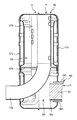
In the
図3は、上記排気ダクト3の斜視図である。図3に示すように、上記触媒収納ケース6と上記排気マフラ7とは、一体に接続されている。つまり、触媒収納ケース6のケース本体60と排気マフラ7のケース本体70とは、一体化されている。
FIG. 3 is a perspective view of the
図4Aは、上記触媒収納ケース6の正面図である。図4Bは、触媒収納ケース6の左側面図である。図4Cは、触媒収納ケース6の正面からみた断面図である。図4Aと図4Bと図4Cに示すように、触媒収納ケース6は、ケース本体60と、ケース本体60内に配置された2つの第1、第2酸化触媒61,62とを有する。
FIG. 4A is a front view of the
上記ケース本体60は、吸入口60aと、排出口60bと、上記吸入口60aから上記排出口60bに延在して排気ガスを通過させるための排気通路60cとを有する。吸入口60aは、シリンダヘッド2の排気ポート22に、連通される。排出口60bは、排気マフラ7に連通される。
The
上記ケース本体60は、第1半体部161と第2半体部162とを有する。第1半体部161と第2半体部162とは、互いに、溶接により接合されている。第1半体部161は、吸入口60a側に、鍔部167を有する。鍔部167は、孔部167aを有する。孔部167aには、図1に示すボルト100が挿入される。これにより、ケース本体60は、ボルト100により、シリンダヘッド2に固定される。ケース本体60の吸入口60aとシリンダヘッド2の排気ポート22とは、シール部材を介して接続される。
The case
上記ケース本体60の排出口60bには、端板163が取り付けられている。端板163には、第1筒部164と第2筒部165とが、貫通した状態で取り付けられている。第1、第2筒部164,165のそれぞれの吸入口60a側の部分は、支持板166により、支持されている。支持板166は、ケース本体60内に取り付けられている。これにより、ケース本体60の内側と外側とは、第1、第2筒部164,165を介して、連通される。
An
上記第1、上記第2筒部164,165は、排気通路60cの延在する方向に対して交差する方向に、並んでいる。具体的に述べると、第1、第2筒部164,165の配列方向は、排気通路60cの延在する方向に対して直交する。
The first and second
上記ケース本体60における吸入口60aと支持板166との間の部分160は、排気通路60cが吸入口60aから支持板166に向かって広くなるように、ラッパ状に形成されている。ラッパ状部分160は、第1、第2筒部164,165のそれぞれに、排気ガスを導くように、形成されている。ラッパ状部分160の上壁160aは、傾きの異なる3つの傾斜面a1,a2,a3により構成されている。
A
上記第1、上記第2酸化触媒61,62は、排気通路60cに配置されている。つまり、第1酸化触媒61は、第1筒部164に挿入され、第2酸化触媒62は、第2筒部165に挿入されている。
The first and
上記第1、上記第2酸化触媒61,62は、排気通路60cの延在する方向に対して交差する方向に、並んでいる。具体的に述べると、第1、第2酸化触媒61,62の配列方向は、排気通路60cの延在する方向に対して直交する。さらに述べると、第1、第2酸化触媒61,62は、クランクシャフト13の軸心L(図1参照)に対して直交する方向に、並んでいる。つまり、クランクシャフト13の軸心Lは、図4の紙面に直交する方向に延在し、第1、第2酸化触媒61,62は、図4の紙面の上下方向に配置される。
The first and
上記第1、上記第2酸化触媒61,62の形状は、円柱を扁平にした形状である。第1、第2酸化触媒61,62は、コージェライトのようなセラミックスよりなるモノリス担体であり、その比表面積を増やすため、格子状またはハニカム形状の多孔質の隔壁で仕切られた多角形断面を有する。これら隔壁は、互いに平行に形成された多数の貫通孔に排出ガスの入口と出口を交互に封止することにより構成される。隔壁には、白金等の触媒金属が担持されており、これにより、酸化触媒機能を有する。
The shapes of the first and
なお、モノリス担体の材質として、コージェライトを用いているが、炭化ケイ素又はステンレス等を用いてもよく、限定するものではない。触媒本体は、比表面積を増やすための構造がなされていればよく、例えば、格子状の金属板の仕切りが多数配置されたメッシュリングであってもよい。触媒金属として、白金を用いているが、パラジウム、ロジウム、イリジウム等を用いてもよく、限定するものではない。 Although cordierite is used as the material of the monolith carrier, silicon carbide or stainless steel may be used and is not limited. The catalyst body only needs to have a structure for increasing the specific surface area. For example, the catalyst body may be a mesh ring in which a large number of grid-like metal plate partitions are arranged. Although platinum is used as the catalyst metal, palladium, rhodium, iridium or the like may be used and is not limited.
上記第1、上記第2酸化触媒61,62は、多孔質の隔壁によって排出ガス中のPM(浮遊粒子状物質)を捕捉する。そして、第1、第2酸化触媒61,62は、触媒金属の担持により、排出ガス中の窒素酸化物(NOx)、一酸化窒素(NO)、一酸化炭素(CO)、炭化水素(HC)などに酸化力を付与し、二酸化炭素、水、二酸化窒素NO2等を生成する。そして、触媒金属により排出ガス中に多く生成されたNO2等の酸化力と、排気ポート22の近傍による排出ガスの高温が利用され、捕集されたPMは連続的に酸化され燃焼除去される。
The first and
図5は、上記排気ダクト3の平面からみた断面図である。図5に示すように、排気マフラ7のケース本体70は、第1半体部171と第2半体部172とを有する。第1半体部171と第2半体部172とは、互いに、溶接により接合されている。
FIG. 5 is a cross-sectional view of the
上記第1半体部171には、触媒収納ケース6のケース本体60が、貫通した状態で取り付けられている。つまり、第1半体部171とケース本体60とは、溶接により、一体に接続されている。なお、第1半体部171とケース本体60とは、ボルトにより、一体に接続されていてもよい。
A case
上記排気マフラ7の上記ケース本体70の内部に、内部配管173と吐出配管174が、配置されている。ケース本体70の内部は、仕切板175により、第1空間S1と第2空間S2に仕切られている。触媒収納ケース6のケース本体60(第1、第2酸化触媒61,62)は、第1空間S1に進入している。内部配管173は、仕切板175を貫通して、第1空間S1と第2空間S2とを連通する。吐出配管174は、仕切板175と第2半体部172を貫通して、第2空間S2とケース本体70の外側とを連通する。
An
これにより、上記第1、上記第2酸化触媒61,62を通過した排気ガスは、第1空間S1に進入してから、内部配管173を通過して、第2空間S2に進入する。その後、排気ガスは、第2空間S2から、吐出配管174を通過して、ケース本体70の外側に排出される。
Thus, the exhaust gas that has passed through the first and
上記構成の触媒収納ケース6によれば、上記第1、上記第2酸化触媒61,62を有し、第1、第2酸化触媒61,62は、排気通路60cの延在する方向に対して交差する方向に、並んでいる。これにより、排気ガスの流れが、ケース本体60内で偏ったとしても、第1、第2酸化触媒61,62のうちの少なくとも1つに、目詰まりが発生することになる。このため、第2酸化触媒62のみに目詰まりが発生したとすると、目詰まりの発生した第2酸化触媒62のみを交換し、目詰まりの発生していない第1酸化触媒61をそのまま用いることができ、酸化触媒61,62の無駄を減らすことができる。
According to the
上記構成の排気ダクト3によれば、上記触媒収納ケース6と上記排気マフラ7とは、一体に接続されているので、排気ダクト3の部品点数を減少でき、排気ダクト3の組立が容易となる。
According to the
上記構成のエンジン10によれば、上記第1、上記第2酸化触媒61,62を有する上記触媒収納ケース6を備えるので、エンジン10を運転して、酸化触媒61,62が排気ガスにより目詰まりしても、酸化触媒61,62を交換する際に酸化触媒61,62の無駄を減らすことができる。
According to the
また、上記第1、上記第2酸化触媒61,62は、クランクシャフト13の軸心Lに対して交差する方向に、並んでいるので、酸化触媒61,62が2つあっても、触媒収納ケース6のクランクシャフト13の軸心L方向の厚みを抑制できる。したがって、触媒収納ケース6が、シリンダブロック1の負荷側に突出することを抑制でき、負荷部材をシリンダブロック1のクランクシャフト13の負荷側端部13aに接続する際に、触媒収納ケース6が、負荷部材に干渉することを防止できる。特に、第1、第2酸化触媒61,62が、クランクシャフト13の軸心Lに対して直交する方向に、並んでいることで、第1、第2酸化触媒61,62は、クランクシャフト13の軸心L方向に沿って並ばず、触媒収納ケース6のクランクシャフト13の軸心L方向の厚みを一層抑制できる。
In addition, since the first and
(第2の実施形態)
図6は、本発明の第2実施形態の触媒収納ケースを示す断面図である。上記第2実施形態は、上記第1実施形態とは、導風板の構成のみが相違する。この相違する構成のみを以下に説明する。なお、上記第2実施形態において、上記第1実施形態と同一の符号は、上記第1実施形態と同じ構成であるため、その説明を省略する。
(Second Embodiment)
FIG. 6 is a cross-sectional view showing a catalyst storage case according to the second embodiment of the present invention. The second embodiment is different from the first embodiment only in the configuration of the air guide plate. Only this different configuration will be described below. Note that in the second embodiment, the same reference numerals as those in the first embodiment have the same configurations as those in the first embodiment, and a description thereof will be omitted.
図6に示すように、第2実施形態の触媒収納ケース6Aは、導風板65を有する。導風板65は、排気通路60cで、第1、第2酸化触媒61,62と吸入口60aとの間に、配置されている。つまり、導風板65は、ケース本体60のラッパ状部分160に配置されている。
As shown in FIG. 6, the
上記導風板65は、図4の白抜きの矢印Aに示すように、第1、第2酸化触媒61,62のそれぞれに排気ガスを導く。導風板65は、各酸化触媒61,62に排気ガスを略均等に導くように、配置されている。具体的に述べると、導風板65は、第1、第2酸化触媒61,62の間と吸入口60aの中心とを通る平面上に配置されている。
The
上記構成の触媒収納ケース6Aによれば、上記導風板65は、各酸化触媒61,62に排気ガスを導くので、各酸化触媒61,62に排気ガスを略均等に導くことができ、第1、第2酸化触媒61,62の目詰まりの偏りを低減できる。
According to the
(第3の実施形態)
図7は、本発明の第3実施形態の排気ダクトを示す斜視図である。上記第3実施形態は、上記第1実施形態とは、排気ダクトの触媒収納ケースの構成のみが相違する。この相違する構成のみを以下に説明する。なお、上記第3実施形態において、上記第1実施形態と同一の符号は、上記第1実施形態と同じ構成であるため、その説明を省略する。
(Third embodiment)
FIG. 7 is a perspective view showing an exhaust duct according to a third embodiment of the present invention. The third embodiment is different from the first embodiment only in the configuration of the catalyst storage case of the exhaust duct. Only this different configuration will be described below. Note that in the third embodiment, the same reference numerals as those in the first embodiment have the same configurations as those in the first embodiment, and a description thereof will be omitted.
図7に示すように、第3実施形態の排気ダクト3Bの触媒収納ケース6Bは、第1実施形態(図4A)の触媒収納ケース6と比べて、ケース本体60Bのラッパ状部分160Bの形状が、異なる。つまり、第1実施形態(図4A)のラッパ状部分160の上壁160aは、傾きの異なる3つの傾斜面a1,a2,a3により構成されていたが、第3実施形態(図7)のラッパ状部分160Bの上壁160bは、傾きの異なる2つの傾斜面b1,b2により構成されている。図7の上流側の傾斜面b1は、図4Aの上流側の2つの傾斜面a1,a2に相当し、図7の下流側の傾斜面b2は、図4Aの下流側の傾斜面a3に相当する。
As shown in FIG. 7, the
なお、本発明は上述の実施形態に限定されず、本発明の要旨を逸脱しない範囲で設計変更可能である。例えば、上記第1から上記第3実施形態のそれぞれの特徴点を様々に組み合わせてもよい。 The present invention is not limited to the above-described embodiment, and the design can be changed without departing from the gist of the present invention. For example, the feature points of the first to third embodiments may be variously combined.
上記実施形態では、エンジンとして、一気筒のディーゼルエンジンを用いたが、多気筒のディーゼルエンジンであってもよい。 In the above embodiment, a one-cylinder diesel engine is used as the engine, but a multi-cylinder diesel engine may be used.
上記実施形態では、酸化触媒は、2つであったが、3つ以上であってもよい。また、導風板は、1つであったが、0または2つ以上であってもよい。 In the above embodiment, there are two oxidation catalysts, but three or more oxidation catalysts may be used. Further, although there is one air guide plate, it may be zero or two or more.
上記実施形態では、2つの酸化触媒は、排気通路の延在する方向に対して、直交する方向に並んでいたが、排気通路の延在する方向に対して、直交でなく交差する方向に並んでいればよい。 In the above-described embodiment, the two oxidation catalysts are arranged in a direction orthogonal to the direction in which the exhaust passage extends. However, the two oxidation catalysts are arranged in a direction that is not orthogonal to the direction in which the exhaust passage extends. Just go out.
上記実施形態では、2つの酸化触媒は、クランクシャフトの軸心に対して、直交する方向に並んでいたが、クランクシャフトの軸心に対して、直交でなく交差する方向に並んでいればよい。 In the above embodiment, the two oxidation catalysts are arranged in a direction orthogonal to the axis of the crankshaft. However, it is only necessary that the two oxidation catalysts are arranged in a direction that is not orthogonal to the axis of the crankshaft. .
上記実施形態では、触媒収納ケースと排気マフラとは、溶接により、一体に接続されていたが、触媒収納ケース(ケース本体)と排気マフラ(ケース本体)とを、一枚の金属板からプレス加工により、継ぎ目なく連続的に一体に接続するようにしてもよい。 In the above embodiment, the catalyst storage case and the exhaust muffler are integrally connected by welding. However, the catalyst storage case (case main body) and the exhaust muffler (case main body) are pressed from a single metal plate. Thus, the connection may be made continuously and seamlessly.
1 シリンダブロック
1a 負荷側端面
2 シリンダヘッド
3,3B 排気ダクト
4 シリンダ
5 クランクケース
6,6A,6B 触媒収納ケース
7 排気マフラ
10 エンジン
11 ピストン
13 クランクシャフト
13a 負荷側端部
15 燃焼室
21 吸気ポート
22 排気ポート
60,60B ケース本体
60a 吸入口
60b 排出口
60c 排気通路
61 第1酸化触媒
62 第2酸化触媒
65 導風板
70 ケース本体
L クランクシャフトの軸心
DESCRIPTION OF
Claims (3)
上記シリンダブロックに取り付けられると共に、上記シリンダ内に連通する排気ポートを有するシリンダヘッドと、
上記シリンダヘッドに取り付けられる触媒収納ケースと
を備え、
上記触媒収納ケースは、
吸入口と、排出口と、上記吸入口から上記排出口に延在して排気ガスを通過させるための排気通路とを、有するケース本体と、
上記ケース本体の上記排気通路に配置された複数の酸化触媒と
を備え、
上記複数の酸化触媒は、上記排気通路の延在する方向に対して交差する方向に、並んでおり、
上記触媒収納ケースの上記吸入口は、上記シリンダヘッドの上記排気ポートに、連通され、
上記シリンダブロックは、上記シリンダ内に配置されたピストンと、上記ピストンに連結されたクランクシャフトとを有し、
上記シリンダブロックは、上記クランクシャフトの負荷側の端部が突出する負荷側端面を有し、
上記触媒収納ケースは、上記シリンダブロックの上記負荷側端面側に配置され、
上記触媒収納ケースの上記複数の酸化触媒は、上記クランクシャフトの軸心に対して直交する方向に、並んでいることを特徴とするエンジン。 A cylinder block having a cylinder;
A cylinder head attached to the cylinder block and having an exhaust port communicating with the cylinder;
A catalyst storage case attached to the cylinder head;
With
The catalyst storage case is
A case body having an inlet, an outlet, and an exhaust passage extending from the inlet to the outlet to allow exhaust gas to pass through;
A plurality of oxidation catalysts arranged in the exhaust passage of the case body,
The plurality of oxidation catalysts are arranged in a direction intersecting the direction in which the exhaust passage extends ,
The suction port of the catalyst storage case communicates with the exhaust port of the cylinder head ,
The cylinder block has a piston disposed in the cylinder, and a crankshaft connected to the piston.
The cylinder block has a load side end surface from which a load side end of the crankshaft projects,
The catalyst storage case is disposed on the load side end face side of the cylinder block,
The plurality of oxidation catalysts of the catalyst storage case, the engine, characterized in that in the direction perpendicular to the axis of the crank shaft are aligned.
上記触媒収納ケースは、上記ケース本体の上記排気通路で上記酸化触媒と上記吸入口との間に配置され、各酸化触媒に排気ガスを導くための導風板を有することを特徴とするエンジン。 The engine according to claim 1,
The catalyst storage case, the engine characterized by having the above exhaust passage of the case body is disposed between the oxidation catalyst and the inlet port, the air guide plate for guiding the exhaust gas to each oxidation catalyst.
上記触媒収納ケースと上記触媒収納ケースの上記排出口に連通される排気マフラとを含む排気ダクトを備え、
上記触媒収納ケースと上記排気マフラとは、一体に接続されていることを特徴とするエンジン。 The engine according to claim 1 or 2 ,
An exhaust duct comprising an exhaust muffler which is communicated with the discharge port of the catalyst storage case and the upper Symbol catalyst storage case,
The engine characterized in that the catalyst storage case and the exhaust muffler are integrally connected.
Priority Applications (7)
| Application Number | Priority Date | Filing Date | Title |
|---|---|---|---|
| JP2014017533A JP6165072B2 (en) | 2014-01-31 | 2014-01-31 | engine |
| KR1020207012085A KR20200047756A (en) | 2014-01-31 | 2015-01-08 | Catalyst case, exhaust duct, and engine |
| PCT/JP2015/050326 WO2015115144A1 (en) | 2014-01-31 | 2015-01-08 | Catalyst case, exhaust duct, and engine |
| CN201580006584.6A CN105940196B (en) | 2014-01-31 | 2015-01-08 | Catalyst accommodating case, exhaust pipe and engine |
| US15/115,395 US10113467B2 (en) | 2014-01-31 | 2015-01-08 | Catalyst storage case, exhaust duct, and engine |
| EP15742981.2A EP3101246B1 (en) | 2014-01-31 | 2015-01-08 | Catalyst case, exhaust duct, and engine |
| KR1020167020077A KR20160108366A (en) | 2014-01-31 | 2015-01-08 | Catalyst case, exhaust duct, and engine |
Applications Claiming Priority (1)
| Application Number | Priority Date | Filing Date | Title |
|---|---|---|---|
| JP2014017533A JP6165072B2 (en) | 2014-01-31 | 2014-01-31 | engine |
Publications (2)
| Publication Number | Publication Date |
|---|---|
| JP2015143510A JP2015143510A (en) | 2015-08-06 |
| JP6165072B2 true JP6165072B2 (en) | 2017-07-19 |
Family
ID=53756722
Family Applications (1)
| Application Number | Title | Priority Date | Filing Date |
|---|---|---|---|
| JP2014017533A Active JP6165072B2 (en) | 2014-01-31 | 2014-01-31 | engine |
Country Status (6)
| Country | Link |
|---|---|
| US (1) | US10113467B2 (en) |
| EP (1) | EP3101246B1 (en) |
| JP (1) | JP6165072B2 (en) |
| KR (2) | KR20160108366A (en) |
| CN (1) | CN105940196B (en) |
| WO (1) | WO2015115144A1 (en) |
Families Citing this family (3)
| Publication number | Priority date | Publication date | Assignee | Title |
|---|---|---|---|---|
| DE102016113756A1 (en) * | 2016-07-26 | 2018-02-01 | Motorenfabrik Hatz Gmbh & Co Kg | Silencer for single-cylinder diesel engine |
| JP6866732B2 (en) * | 2017-04-03 | 2021-04-28 | スズキ株式会社 | Exhaust system for saddle-mounted vehicles |
| WO2022087279A1 (en) * | 2020-10-22 | 2022-04-28 | Cummins Emission Solutions Inc. | Exhaust gas aftertreatment system |
Family Cites Families (15)
| Publication number | Priority date | Publication date | Assignee | Title |
|---|---|---|---|---|
| JPS6412015A (en) * | 1987-07-01 | 1989-01-17 | Hino Motors Ltd | Exhaust gas purification device |
| JPH0610409B2 (en) * | 1987-10-19 | 1994-02-09 | 新キャタピラー三菱株式会社 | Engine smoke reduction device |
| US4884398A (en) * | 1987-10-19 | 1989-12-05 | Shin Caterpillar Mitsubishi Ltd. | Method of and apparatus for reducing engine smoke emissions |
| JPH0610410B2 (en) * | 1987-10-19 | 1994-02-09 | 新キャタピラー三菱株式会社 | How to reduce engine smoke |
| JPH068722U (en) * | 1992-07-08 | 1994-02-04 | 日産ディーゼル工業株式会社 | Catalytic device for internal combustion engine |
| JPH0814033A (en) * | 1994-06-24 | 1996-01-16 | Caterpillar Inc | Module catalytic converter for internal combustion engine and muffler |
| JP4330048B2 (en) * | 1999-06-11 | 2009-09-09 | ヤマハ発動機株式会社 | Multi-cylinder 4-cycle engine for outboard motor |
| JP2003083046A (en) * | 2001-09-11 | 2003-03-19 | Honda Motor Co Ltd | Exhaust system cooling device for engine |
| JP2003214143A (en) * | 2002-01-24 | 2003-07-30 | Ooden:Kk | Diesel particulate removing device and diesel vehicle provided with the same |
| JP2003214142A (en) * | 2002-01-24 | 2003-07-30 | Ooden:Kk | Diesel particulate removing device and diesel vehicle provided with the same |
| JP2006009648A (en) * | 2004-06-24 | 2006-01-12 | Honda Motor Co Ltd | Exhaust emission control device for motorcycle |
| JP4654763B2 (en) * | 2005-05-23 | 2011-03-23 | スズキ株式会社 | Engine exhaust system |
| JP5046674B2 (en) * | 2007-02-07 | 2012-10-10 | 本田技研工業株式会社 | Catalyst arrangement structure for motorcycles |
| JP5846381B2 (en) | 2012-05-18 | 2016-01-20 | 三菱自動車工業株式会社 | Exhaust gas purification device for internal combustion engine |
| WO2015015619A1 (en) | 2013-08-01 | 2015-02-05 | Miyashita Michiko | Exhaust gas purification system |
-
2014
- 2014-01-31 JP JP2014017533A patent/JP6165072B2/en active Active
-
2015
- 2015-01-08 WO PCT/JP2015/050326 patent/WO2015115144A1/en active Application Filing
- 2015-01-08 US US15/115,395 patent/US10113467B2/en active Active
- 2015-01-08 KR KR1020167020077A patent/KR20160108366A/en not_active Application Discontinuation
- 2015-01-08 CN CN201580006584.6A patent/CN105940196B/en not_active Expired - Fee Related
- 2015-01-08 KR KR1020207012085A patent/KR20200047756A/en not_active IP Right Cessation
- 2015-01-08 EP EP15742981.2A patent/EP3101246B1/en active Active
Also Published As
| Publication number | Publication date |
|---|---|
| CN105940196A (en) | 2016-09-14 |
| KR20200047756A (en) | 2020-05-07 |
| KR20160108366A (en) | 2016-09-19 |
| EP3101246B1 (en) | 2020-03-04 |
| WO2015115144A1 (en) | 2015-08-06 |
| US20170002712A1 (en) | 2017-01-05 |
| US10113467B2 (en) | 2018-10-30 |
| EP3101246A4 (en) | 2017-08-30 |
| CN105940196B (en) | 2019-02-15 |
| EP3101246A1 (en) | 2016-12-07 |
| JP2015143510A (en) | 2015-08-06 |
Similar Documents
| Publication | Publication Date | Title |
|---|---|---|
| US8015802B2 (en) | Exhaust gas purification device for internal combustion engine | |
| US8821608B2 (en) | Exhaust gas purification device | |
| US5378435A (en) | Silencer combined with catalytic converter for internal combustion engines and modular diaphragm elements for said silencer | |
| US9976460B2 (en) | Exhaust after-treatment assembly for engine system | |
| US10247079B2 (en) | Exhaust gas purification system of internal combustion engine having turbocharger | |
| JP6165072B2 (en) | engine | |
| US20090094964A1 (en) | Exhaust purification apparatus for engine | |
| WO2016194201A1 (en) | Exhaust pipe structure for internal combustion engine | |
| JP2005299419A (en) | Exhaust muffler with exhaust emission control function for engine | |
| JP2009197695A5 (en) | ||
| JP2009197695A (en) | Exhaust emission control device | |
| JP5496145B2 (en) | Muffler for general-purpose internal combustion engine | |
| JP5856641B2 (en) | Exhaust gas purification device | |
| US11267333B2 (en) | Exhaust gas purification device | |
| JP2012140964A (en) | Exhaust gas purifier | |
| JP2011208572A (en) | Exhaust emission treatment device for diesel engine | |
| KR20110042208A (en) | Filtration device for exhaust gases | |
| JP5368839B2 (en) | engine | |
| JP2013217378A (en) | Engine | |
| WO2013005452A1 (en) | Exhaust gas purification device | |
| JP5368838B2 (en) | engine | |
| JP2014211123A (en) | Internal combustion engine diesel particulate filter | |
| JP2021076116A (en) | Catalytic converter, exhaust gas aftertreatment system and internal combustion engine | |
| US20150064079A1 (en) | Catalyst substrate module for exhaust aftertreatment system | |
| JP5937857B2 (en) | piston |
Legal Events
| Date | Code | Title | Description |
|---|---|---|---|
| RD04 | Notification of resignation of power of attorney |
Free format text: JAPANESE INTERMEDIATE CODE: A7424 Effective date: 20150630 |
|
| A621 | Written request for application examination |
Free format text: JAPANESE INTERMEDIATE CODE: A621 Effective date: 20160322 |
|
| A131 | Notification of reasons for refusal |
Free format text: JAPANESE INTERMEDIATE CODE: A131 Effective date: 20170207 |
|
| A521 | Request for written amendment filed |
Free format text: JAPANESE INTERMEDIATE CODE: A523 Effective date: 20170407 |
|
| TRDD | Decision of grant or rejection written | ||
| A01 | Written decision to grant a patent or to grant a registration (utility model) |
Free format text: JAPANESE INTERMEDIATE CODE: A01 Effective date: 20170613 |
|
| A61 | First payment of annual fees (during grant procedure) |
Free format text: JAPANESE INTERMEDIATE CODE: A61 Effective date: 20170620 |
|
| R150 | Certificate of patent or registration of utility model |
Ref document number: 6165072 Country of ref document: JP Free format text: JAPANESE INTERMEDIATE CODE: R150 |
|
| R250 | Receipt of annual fees |
Free format text: JAPANESE INTERMEDIATE CODE: R250 |
|
| S533 | Written request for registration of change of name |
Free format text: JAPANESE INTERMEDIATE CODE: R313533 |
|
| R350 | Written notification of registration of transfer |
Free format text: JAPANESE INTERMEDIATE CODE: R350 |