JP6157818B2 - X-ray diagnostic equipment - Google Patents
X-ray diagnostic equipment Download PDFInfo
- Publication number
- JP6157818B2 JP6157818B2 JP2012191623A JP2012191623A JP6157818B2 JP 6157818 B2 JP6157818 B2 JP 6157818B2 JP 2012191623 A JP2012191623 A JP 2012191623A JP 2012191623 A JP2012191623 A JP 2012191623A JP 6157818 B2 JP6157818 B2 JP 6157818B2
- Authority
- JP
- Japan
- Prior art keywords
- image
- ray
- aperture
- roi
- unit
- Prior art date
- Legal status (The legal status is an assumption and is not a legal conclusion. Google has not performed a legal analysis and makes no representation as to the accuracy of the status listed.)
- Active
Links
- 230000007246 mechanism Effects 0.000 claims description 24
- 238000003745 diagnosis Methods 0.000 claims description 2
- 238000002594 fluoroscopy Methods 0.000 description 68
- 238000000034 method Methods 0.000 description 50
- 239000002131 composite material Substances 0.000 description 34
- 230000008569 process Effects 0.000 description 21
- 238000002679 ablation Methods 0.000 description 15
- 238000010586 diagram Methods 0.000 description 15
- 238000003384 imaging method Methods 0.000 description 15
- 239000000203 mixture Substances 0.000 description 13
- 230000000994 depressogenic effect Effects 0.000 description 12
- 238000001514 detection method Methods 0.000 description 12
- 230000008859 change Effects 0.000 description 8
- 230000004044 response Effects 0.000 description 6
- 125000002066 L-histidyl group Chemical group [H]N1C([H])=NC(C([H])([H])[C@](C(=O)[*])([H])N([H])[H])=C1[H] 0.000 description 5
- 238000006073 displacement reaction Methods 0.000 description 5
- 239000012141 concentrate Substances 0.000 description 3
- 238000005259 measurement Methods 0.000 description 3
- 206010003119 arrhythmia Diseases 0.000 description 1
- 230000006793 arrhythmia Effects 0.000 description 1
- 230000015572 biosynthetic process Effects 0.000 description 1
- 210000004556 brain Anatomy 0.000 description 1
- 230000000694 effects Effects 0.000 description 1
- 238000001839 endoscopy Methods 0.000 description 1
- 230000006870 function Effects 0.000 description 1
- 239000004973 liquid crystal related substance Substances 0.000 description 1
- 210000003141 lower extremity Anatomy 0.000 description 1
- 239000000463 material Substances 0.000 description 1
- 238000012986 modification Methods 0.000 description 1
- 230000004048 modification Effects 0.000 description 1
- 238000003786 synthesis reaction Methods 0.000 description 1
- 230000002194 synthesizing effect Effects 0.000 description 1
- 230000001960 triggered effect Effects 0.000 description 1
- 230000000007 visual effect Effects 0.000 description 1
Images


Classifications
-
- A—HUMAN NECESSITIES
- A61—MEDICAL OR VETERINARY SCIENCE; HYGIENE
- A61B—DIAGNOSIS; SURGERY; IDENTIFICATION
- A61B6/00—Apparatus for radiation diagnosis, e.g. combined with radiation therapy equipment
- A61B6/06—Diaphragms
-
- A—HUMAN NECESSITIES
- A61—MEDICAL OR VETERINARY SCIENCE; HYGIENE
- A61B—DIAGNOSIS; SURGERY; IDENTIFICATION
- A61B6/00—Apparatus for radiation diagnosis, e.g. combined with radiation therapy equipment
- A61B6/02—Devices for diagnosis sequentially in different planes; Stereoscopic radiation diagnosis
- A61B6/022—Stereoscopic imaging
-
- A—HUMAN NECESSITIES
- A61—MEDICAL OR VETERINARY SCIENCE; HYGIENE
- A61B—DIAGNOSIS; SURGERY; IDENTIFICATION
- A61B6/00—Apparatus for radiation diagnosis, e.g. combined with radiation therapy equipment
- A61B6/44—Constructional features of apparatus for radiation diagnosis
- A61B6/4417—Constructional features of apparatus for radiation diagnosis related to combined acquisition of different diagnostic modalities
-
- A—HUMAN NECESSITIES
- A61—MEDICAL OR VETERINARY SCIENCE; HYGIENE
- A61B—DIAGNOSIS; SURGERY; IDENTIFICATION
- A61B6/00—Apparatus for radiation diagnosis, e.g. combined with radiation therapy equipment
- A61B6/46—Apparatus for radiation diagnosis, e.g. combined with radiation therapy equipment with special arrangements for interfacing with the operator or the patient
- A61B6/461—Displaying means of special interest
- A61B6/463—Displaying means of special interest characterised by displaying multiple images or images and diagnostic data on one display
-
- A—HUMAN NECESSITIES
- A61—MEDICAL OR VETERINARY SCIENCE; HYGIENE
- A61B—DIAGNOSIS; SURGERY; IDENTIFICATION
- A61B6/00—Apparatus for radiation diagnosis, e.g. combined with radiation therapy equipment
- A61B6/46—Apparatus for radiation diagnosis, e.g. combined with radiation therapy equipment with special arrangements for interfacing with the operator or the patient
- A61B6/467—Apparatus for radiation diagnosis, e.g. combined with radiation therapy equipment with special arrangements for interfacing with the operator or the patient characterised by special input means
-
- A—HUMAN NECESSITIES
- A61—MEDICAL OR VETERINARY SCIENCE; HYGIENE
- A61B—DIAGNOSIS; SURGERY; IDENTIFICATION
- A61B6/00—Apparatus for radiation diagnosis, e.g. combined with radiation therapy equipment
- A61B6/48—Diagnostic techniques
- A61B6/481—Diagnostic techniques involving the use of contrast agents
-
- A—HUMAN NECESSITIES
- A61—MEDICAL OR VETERINARY SCIENCE; HYGIENE
- A61B—DIAGNOSIS; SURGERY; IDENTIFICATION
- A61B6/00—Apparatus for radiation diagnosis, e.g. combined with radiation therapy equipment
- A61B6/48—Diagnostic techniques
- A61B6/486—Diagnostic techniques involving generating temporal series of image data
- A61B6/487—Diagnostic techniques involving generating temporal series of image data involving fluoroscopy
-
- A—HUMAN NECESSITIES
- A61—MEDICAL OR VETERINARY SCIENCE; HYGIENE
- A61B—DIAGNOSIS; SURGERY; IDENTIFICATION
- A61B6/00—Apparatus for radiation diagnosis, e.g. combined with radiation therapy equipment
- A61B6/48—Diagnostic techniques
- A61B6/488—Diagnostic techniques involving pre-scan acquisition
-
- A—HUMAN NECESSITIES
- A61—MEDICAL OR VETERINARY SCIENCE; HYGIENE
- A61B—DIAGNOSIS; SURGERY; IDENTIFICATION
- A61B6/00—Apparatus for radiation diagnosis, e.g. combined with radiation therapy equipment
- A61B6/52—Devices using data or image processing specially adapted for radiation diagnosis
- A61B6/5211—Devices using data or image processing specially adapted for radiation diagnosis involving processing of medical diagnostic data
- A61B6/5229—Devices using data or image processing specially adapted for radiation diagnosis involving processing of medical diagnostic data combining image data of a patient, e.g. combining a functional image with an anatomical image
- A61B6/5235—Devices using data or image processing specially adapted for radiation diagnosis involving processing of medical diagnostic data combining image data of a patient, e.g. combining a functional image with an anatomical image combining images from the same or different ionising radiation imaging techniques, e.g. PET and CT
-
- A—HUMAN NECESSITIES
- A61—MEDICAL OR VETERINARY SCIENCE; HYGIENE
- A61B—DIAGNOSIS; SURGERY; IDENTIFICATION
- A61B6/00—Apparatus for radiation diagnosis, e.g. combined with radiation therapy equipment
- A61B6/44—Constructional features of apparatus for radiation diagnosis
- A61B6/4429—Constructional features of apparatus for radiation diagnosis related to the mounting of source units and detector units
- A61B6/4435—Constructional features of apparatus for radiation diagnosis related to the mounting of source units and detector units the source unit and the detector unit being coupled by a rigid structure
- A61B6/4441—Constructional features of apparatus for radiation diagnosis related to the mounting of source units and detector units the source unit and the detector unit being coupled by a rigid structure the rigid structure being a C-arm or U-arm
-
- A—HUMAN NECESSITIES
- A61—MEDICAL OR VETERINARY SCIENCE; HYGIENE
- A61B—DIAGNOSIS; SURGERY; IDENTIFICATION
- A61B6/00—Apparatus for radiation diagnosis, e.g. combined with radiation therapy equipment
- A61B6/54—Control of apparatus or devices for radiation diagnosis
- A61B6/542—Control of apparatus or devices for radiation diagnosis involving control of exposure
Description
本発明の実施形態は、X線診断装置に関する。 Embodiments described herein relate generally to an X-ray diagnostic apparatus.
アブレーション手技において、カテーテルやガイドワイヤ等を心臓等の治療部位に進めるためにX線診断装置が利用されている。このアブレーション手技は、長時間に亘ることが多く、数時間かかることもしばしばである。従ってアブレーション手技時における、被検体や操作者の被曝低減のための技術が開発されている。 In an ablation procedure, an X-ray diagnostic apparatus is used to advance a catheter, a guide wire, and the like to a treatment site such as the heart. This ablation procedure often takes a long time and often takes several hours. Therefore, techniques for reducing the exposure of subjects and operators during ablation procedures have been developed.
被曝低減のための技術の一つにROI内透視と呼ばれる技術がある。ROI内透視においては、手技に必要なROIに限定して透視を行って即時的に透視画像(ROI画像)を生成し、このROI画像を動画として即時的に表示している。ROI内透視の応用として、ROI内透視前に生成された広範囲の静止画に、即時的に生成されたROI画像を合成し、合成画像を動画として即時的に表示する技術がある。ROI内透視は、アブレーション手技を始め、下肢や脳の手技にも使用され得る。 One technique for reducing exposure is a technique called ROI fluoroscopy. In the ROI fluoroscopy, a fluoroscopic image (ROI image) is generated immediately by limiting the ROI required for the procedure, and the ROI image is immediately displayed as a moving image. As an application of fluoroscopy in ROI, there is a technique of synthesizing a ROI image generated immediately with a wide range of still images generated before fluoroscopy in ROI and displaying the synthesized image as a moving image immediately. ROI fluoroscopy can be used for ablation procedures as well as lower limb and brain procedures.
しかしながら、アブレーション等のROI内透視が使用される手技では、アームや天板が動かされたり、視野サイズの変更が行われたりすることが多い。また、ROI内透視が使用される手技は、長時間行われるので被検体が動いてしまう場合が多い。従って、静止画とROI画像との位置ずれが頻繁に発生してしまう。静止画とROI画像との位置ずれを解消するため、静止画を更新する必要がある。このため、操作者は、フットスイッチを踏みかえるなどしてROI内透視を中断し、通常の透視に切り替えて、最新の静止画を撮りなおしている。このように操作者は、静止画を更新する際、スイッチを操作するので、手技を中断せざるを得ない。 However, in a technique in which ROI fluoroscopy such as ablation is used, an arm or a top plate is often moved or a visual field size is changed. In addition, since the technique using ROI fluoroscopy is performed for a long time, the subject often moves. Therefore, the positional deviation between the still image and the ROI image frequently occurs. In order to eliminate the positional deviation between the still image and the ROI image, it is necessary to update the still image. For this reason, the operator interrupts fluoroscopy within the ROI by stepping on a foot switch or the like, switches to normal fluoroscopy, and takes the latest still image again. As described above, since the operator operates the switch when updating the still image, the operator is forced to interrupt the procedure.
目的は、手技効率の向上を可能とするX線診断装置を提供することにある。 An object is to provide an X-ray diagnostic apparatus that can improve the procedure efficiency.
本実施形態に係るX線診断装置は、X線を発生するX線管と、前記X線管から発生され被検体を透過したX線を検出するX線検出器と、前記X線管からのX線の照射野を限定するための開口可変の絞り機構と、前記絞り機構の開口が第1の開口である期間において前記X線検出器の出力に基づいて第1のX線画像を生成し、前記絞り機構の開口が前記第1の開口よりも狭い第2の開口である期間において前記X線検出器の出力に基づいて第2のX線画像を繰り返し生成する画像生成部と、前記第2のX線画像が発生される毎に、前記繰り返し生成される第2のX線画像のうちの最新の第2のX線画像を動画として前記第1のX線画像とともに表示する表示部と、第1のX線画像を繰り返し生成させるためのX線の照射を実行させる操作を受け付ける第1の入力スイッチと、第2のX線画像を繰り返し生成させるためのX線の照射を実行させる操作を受け付ける第2の入力スイッチとを有するフットスイッチ部と、前記第2の入力スイッチを踏む操作が受け付けられると、前記第1のX線画像を再度取得するために、前記絞り機構を制御して前記絞り機構の開口を前記第2の開口から前記第1の開口に拡大させて前記第1のX線画像を取得した後、自動的に前記絞り機構を前記第2の開口に縮小させる制御を行い、前記第2の入力スイッチを踏む操作が終了するまで、前記絞り機構の開口を前記第2の開口にした状態で前記第2のX線画像を繰り返し生成させる制御を行う制御部と、を具備する。 An X-ray diagnostic apparatus according to the present embodiment includes an X-ray tube that generates X-rays, an X-ray detector that detects X-rays generated from the X-ray tube and transmitted through a subject, and the X-ray tube An aperture mechanism with a variable aperture for limiting the X-ray irradiation field, and a first X-ray image is generated based on the output of the X-ray detector in a period in which the aperture of the aperture mechanism is the first aperture. An image generating unit that repeatedly generates a second X-ray image based on an output of the X-ray detector in a period in which the aperture of the aperture mechanism is a second aperture narrower than the first aperture; A display unit that displays the latest second X-ray image among the repeatedly generated second X-ray images as a moving image together with the first X-ray image each time two X-ray images are generated; receives an operation to perform the irradiation of X-rays for generating repeatedly a first X-ray image Takes a first input switch, a foot switch unit having a second input switch for accepting the operation to execute the X-ray irradiation for repeatedly generating a second X-ray image, the second input switch When a stepping operation is accepted, in order to acquire the first X-ray image again, the aperture mechanism is controlled to expand the aperture of the aperture mechanism from the second aperture to the first aperture, and After acquiring the first X-ray image, control is performed to automatically reduce the aperture mechanism to the second aperture, and the aperture of the aperture mechanism is opened until the operation of stepping on the second input switch is completed. A control unit that performs control to repeatedly generate the second X-ray image in the second opening state.
以下、図面を参照しながら本実施形態に係わるX線診断装置を説明する。なお、本実施形態は、ROI内透視の技術を装備したX線診断装置を対象とする。 The X-ray diagnostic apparatus according to this embodiment will be described below with reference to the drawings. Note that this embodiment is directed to an X-ray diagnostic apparatus equipped with ROI endoscopy technology.
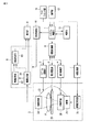
まず、図1を参照しながら本実施形態に係るX線診断装置の構成について説明する。図1は、本実施形態に係るX線診断装置の構成を示す図である。図1に示すように、本実施形態に係るX線診断装置は、システム制御部1を中枢として、撮像機構2、Cアーム駆動部3、絞り駆動部4、寝台駆動部5、駆動制御部6、X線制御部7、画像処理部8、表示部9、表示制御部10、フットスイッチ部11、操作部12、及び判定部13を有している。
First, the configuration of the X-ray diagnostic apparatus according to the present embodiment will be described with reference to FIG. FIG. 1 is a diagram illustrating a configuration of an X-ray diagnostic apparatus according to the present embodiment. As shown in FIG. 1, the X-ray diagnostic apparatus according to the present embodiment has an imaging mechanism 2, a C arm drive unit 3, an aperture drive unit 4, a
図2は、撮像機構2の外観を示す図である。図2や図1に示すように、撮像機構2は、床に旋回可能又は固定して設置されたCアームホルダ21を有している。Cアームホルダ21は、Cアーム22を軸A1回りに回転可能に支持している。Cアームホルダ21は、Cアーム駆動部3からの駆動信号の供給を受けて、軸A1回りにCアーム22を回転する。また、Cアームホルダ21は、軸A1に直交する軸A2回りにスライド可能にCアーム22を支持している。Cアームホルダ21は、Cアーム駆動部3からの駆動信号の供給を受けて、軸A2回りにCアーム22をC形状に沿ってスライドする。Cアーム駆動部3は、駆動制御部6からの制御信号に応じて駆動信号をCアームホルダ21に供給する。軸A1と軸A2との交点は、アイソセンタと呼ばれている。Cアーム22は、アイソセンタが常に空間的に固定された状態で、軸A1回りに回転したり、軸A2回りにスライドしたりする。
FIG. 2 is a diagram illustrating an appearance of the imaging mechanism 2. As shown in FIGS. 2 and 1, the imaging mechanism 2 has a C-
Cアーム22は、X線管23とX線検出器24とを互いに向き合わせて装備している。
The
X線管24は、高電圧発生器25からの高電圧の印加とフィラメント電流の供給とを受けてX線を発生する。高電圧発生器25は、X線制御部7からの制御信号に応じて高電圧を印加したり、フィラメント電流を供給したりする。透視モードの場合、X線管23からは、X線制御部7の制御に応じた比較的線量が低いX線が連続的に発生される。撮影モードの場合、X線管23からは、X線制御部7の制御に応じた、透視モードよりも比較的線量が高いX線が単発的に発生される。
The
X線検出器24は、X線管23から発生されたX線を検出する。例えば、X線検出器24は、フラットパネルディスプレイ(FPD)により実現される。X線検出器24は、2次元上に配列された複数の検出素子を有している。各検出素子は、X線管23から発生されたX線を検出し、検出されたX線の強度に応じた電気信号を生成する。生成された電気信号は、画像処理部8に供給される。
The
X線管23には、X線絞り器26が取り付けられている。X線絞り器26は、開口のサイズや形状を変更可能な可動絞りである。具体的には、X線絞り器26は、X線を遮蔽する物質により構成された絞り羽根を移動可能に支持している。絞り羽根により開口が規定される。絞り羽根は、例えば、鉛により形成される。X線絞り器26は、絞り駆動部4に電気的に接続されている。X線絞り器26と絞り駆動部4とにより、X線管23からのX線の照射野を限定するための開口可変の絞り機構が構成される。X線絞り器26は、絞り駆動部4からの駆動信号の供給を受けて絞り羽根を移動する。絞り駆動部4は、駆動制御部6からの制御信号に応じて駆動信号をX線絞り器26に供給する。絞り羽根が移動されることで開口のサイズや形状が変化される。X線絞り器26により開口のサイズ及び位置が調整されることで、X線検出器24の検出面へのX線照射領域のサイズ及び位置が調整される。例えば、X線絞り器26は、駆動制御部6からの制御に従って開口を第1開口と第2開口とで交互に切り替える。第2開口は、第1開口よりもサイズが狭いものとする。ここで、第1開口を大開口、第2開口を小開口と呼ぶことにする。なお、絞り羽根のサイズや位置は、後述するように、操作者により操作部12を介してROIのサイズや位置が指定又は変更されることに連動してX線絞り器26により調整される。
An
画像処理部8は、X線検出器24からの電気信号に基づいて被検体Pに関するX線画像を生成する。具体的には、画像処理部8は、画像生成部81、画像記憶部83、及び画像合成部85を有する。画像生成部81は、X線検出器24の各検出素子から電気信号を読み出して、読み出された電気信号に基づいてX線画像を生成する。画像生成部81は、X線管23からX線が発生されている間、所定時間(例えば、数ミリ秒オーダー)毎にX線画像を繰り返し生成する。生成されたX線画像は、画像記憶部83や画像合成部85、表示部9に供給される。ここで、開口が大開口の期間において画像生成部81により生成されるX線画像を大開口画像、開口が小開口の期間において画像生成部81により生成されるX線画像を小開口画像と呼ぶことにする。画像合成部85は、リアルタイムに生成される小開口画像と、繰り返し生成された大開口画像のうちの特定の大開口画像とを合成し、合成画像を生成する。典型的には、特定の大開口画像は、その時点における最新の大開口画像である。すなわち、大開口画像は、合成画像における静止画に利用される。生成された合成画像は、表示部9に供給される。なお、表示部9にX線画像(大開口画像又は小開口画像)を供給するか、合成画像を供給するかは、システム制御部1による制御に従って表示制御部10により切り替えられる。
The
表示部9は、画像生成部81からのX線画像や画像合成部85からの合成画像を表示する。表示部9としては、CRTディスプレイや、液晶ディスプレイ、有機ELディスプレイ、プラズマディスプレイ等が適宜利用可能である。
The
また、図1や図2に示すように、撮像機構2には、寝台27が設けられている。寝台27は、脚部28を有している。脚部28は、被検体Pが載置される天板29を水平方向及び鉛直方向に移動可能に支持する。脚部28は、寝台駆動部5に電気的に接続されている。寝台駆動部5は、駆動制御部6からの制御信号に応じた駆動信号を脚部28に供給する。寝台駆動部5は、例えば、ステッピングモータ等のモータにより構成される。駆動信号が供給されると脚部28は、天板29を駆動信号に応じて水平方向や鉛直方向に移動する。
As shown in FIGS. 1 and 2, the imaging mechanism 2 is provided with a
また、脚部28の下部には、フットスイッチ部11が設けられている。フットスイッチ部11は、操作者の足により操作される複数のスイッチを装備している。例えば、フットスイッチ部11は、X線透視を行うためのスイッチやROI内透視を行うためのスイッチ等を有している。フットスイッチ部11の詳細については後述する。フットスイッチ部11の操作により生成される操作信号は、システム制御部11に供給される。
In addition, a
操作部12は、操作者から入力デバイスを介して各種指令や情報入力を受け付け、受付けた指令や情報に応じた操作信号をシステム制御部1に供給する。例えば、操作部12は、操作者からの入力デバイスを介した指示に従ってROIを設定する。入力デバイスは、フットスイッチ部11とは別体に設けられている。入力デバイスとしては、例えば、キーボードやマウス、ボタン、スイッチ、タッチキーパネル等が適用可能である。
The
判定部13は、表示されている合成画像における大開口画像を更新するか否かを、大開口画像と小開口画像との解剖学的な位置ずれに関する指標(以下、位置ずれ指標と呼ぶことにする。)に基づいて判定する。判定部13による処理の詳細は、後述する。
The
駆動制御部6は、システム制御部1による制御に従ってCアーム駆動部3、絞り駆動部4、及び寝台駆動部5を制御する。例えば、駆動制御部6は、Cアーム22を操作者指定の位置に移動させるために、Cアーム駆動部3に制御信号を供給する。制御信号の供給を受けてCアーム駆動部3は、Cアーム22を操作者指定の位置に移動させるために、Cアームホルダ21に駆動信号を供給する。また、駆動制御部6は、天板29を操作者指定の位置に移動させるために、寝台駆動部5に制御信号を供給する。制御信号の供給を受けて寝台駆動部5は、天板19を操作者指定の位置に移動させるために、脚部28に駆動信号を供給する。また、駆動制御部6は、絞り羽根により規定される開口を操作者指定のサイズや位置に変更させるために、絞り駆動部4に制御信号を供給する。制御信号の供給を受けて絞り駆動部4は、開口を操作者指定のサイズや位置に変更させるために、X線絞り器26に駆動信号を供給する。例えば、駆動制御部6は、判定部13により大開口画像を更新すると判定された場合、開口を小開口から大開口に拡大するために、絞り駆動部4を制御する。一方、判定部13により大開口画像を更新しないと判定された場合、駆動制御部6は、開口を小開口に維持するために、絞り駆動部4を制御する。また、駆動制御部6は、フットスイッチ部11や操作部12からの指示に従って開口を変化させるために、絞り駆動部4を制御しても良い。
The drive control unit 6 controls the C arm drive unit 3, the diaphragm drive unit 4, and the
システム制御部1は、本実施形態に係るX線診断装置の中枢として機能し、ROI内透視における自動開口制御を実行する。 The system control unit 1 functions as the center of the X-ray diagnostic apparatus according to the present embodiment, and executes automatic opening control in ROI fluoroscopy.
以下、システム制御部1の制御のもとに行われる、ROI内透視における自動開口制御処理について説明する。なお、以下の説明を具体的に行うため、ROI内透視の臨床応用例としてアブレーション手技を具体例に挙げて説明する。アブレーション手技は、心臓の治療手法の一つである。アブレーション手技は、不整脈を起こしている原因の部位を、カテーテルの先端から高周波電流を流して、カテーテルの先端に接触している生体組織を小さく焼き切る手技である。アブレーション手技におけるカテーテルのナビゲーションのためにX線診断装置が利用されている。アブレーション手技は、長時間に亘ることが多い。従ってアブレーション手技において、操作者や被検体の被曝量低減のためにROI内透視モードを活用することが有効である。 Hereinafter, an automatic opening control process in the ROI fluoroscopy performed under the control of the system control unit 1 will be described. In order to specifically describe the following, an ablation technique will be described as a specific example of clinical application of fluoroscopy within the ROI. Ablation procedures are one method of treating the heart. The ablation technique is a technique in which a high-frequency current is passed from the distal end of the catheter and a living tissue in contact with the distal end of the catheter is burned down to a small part at the cause of the arrhythmia. X-ray diagnostic devices are used for catheter navigation in ablation procedures. Ablation procedures often take a long time. Therefore, in the ablation technique, it is effective to use the ROI fluoroscopic mode for reducing the exposure dose of the operator and the subject.
まずは、操作部12によるROIの設定について説明する。図3は、ROIの設定を説明するための図である。図3に示すように、ROIは、表示部9に表示されているX線画像上で設定される。ROIの設定に利用されるX線画像は、典型的には、X線撮影又は透視により得られた大開口画像である。この場合の大開口画像は、典型的には、X線絞り器26の開口が、X線検出器24の検出面の全体にX線が照射されるように設定されている期間に生成されたX線画像である。
First, the setting of ROI by the
操作者は、表示された大開口画像上において、手技中にリアルタイムで観察したい画像領域をマウス等の入力デバイスを介して指定する。指定された画像領域がROIに設定される。ROIの位置情報は、システム制御部1を介して駆動制御部6に供給される。 The operator designates an image region to be observed in real time during the procedure on the displayed large opening image via an input device such as a mouse. The designated image area is set as the ROI. The ROI position information is supplied to the drive control unit 6 via the system control unit 1.
ROIが設定されると、駆動制御部6は、絞り駆動部4を制御し、ROIの位置情報に応じて開口のサイズ及び位置を変更する。すなわち、X線検出面のうちのROIに相当する局所領域のみにX線が照射されるように開口が設定される。 When the ROI is set, the drive controller 6 controls the aperture driver 4 to change the size and position of the opening according to the position information of the ROI. That is, the aperture is set so that only the local region corresponding to the ROI in the X-ray detection surface is irradiated with X-rays.
次にフットスイッチ部11の詳細について説明する。図4は、フットスイッチ部11を模式的に示す図である。図4に示すように、フットスイッチ部11は、例えば、撮影スイッチ111、透視スイッチ113、及びROI内透視スイッチ115を装備している。
Next, details of the
撮影スイッチ111は、撮像モードを撮影モードに切り替えるためのスイッチである。撮影スイッチ111が踏まれている期間、システム制御部1は、X線制御部7に撮影モードを実行させる。この場合、X線制御部7は、撮影モードに応じた線量のX線をX線管23から発生させるために、高電圧発生器25を制御する。なお、撮影モードに応じた線量は、透視モードに応じた線量よりも高く設定されている。
The
透視スイッチ113は、撮像モードを透視モードに切り替えるためのスイッチである。透視スイッチ113が踏まれている期間、システム制御部1は、X線制御部7に透視モードを実行させる。この場合、X線制御部7は、透視モードに応じた線量のX線をX線管23から発生させるために、高電圧発生器25を制御する。また、システム制御部1は、透視スイッチ113が踏まれている期間、絞り駆動部4を制御し、開口を大開口に設定する。すなわち、透視スイッチ113が踏まれている期間、大開口画像が繰り返し生成される。大開口画像は、合成画像において静止画として利用される。
The
ROI内透視スイッチ115は、撮像モードをROI内透視モードに切り替えるためのスイッチである。ROI内透視スイッチ115が踏まれている期間、システム制御部1は、X線制御部7に透視モードを実行させる。この場合、X線制御部7は、透視モードに応じた線量のX線をX線管23から発生させるために、高電圧発生器25を制御する。また、システム制御部1は、ROI内透視スイッチ115が踏まれている期間、絞り駆動部4を制御し、開口をROIに対応する開口(小開口)に設定する。すなわち、ROI内透視スイッチ115が踏まれている期間、小開口画像が繰り返し生成される。以下、開口がROIに対応する開口に設定されている期間に生成される小開口画像をROI画像と呼ぶことにする。
The ROI
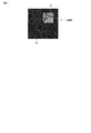
図5は、ROI画像I1の一例を示す図である。図5に示すように、ROI画像I1は、ROI領域R1と空領域R2とを含む。ROI領域R1は、X線検出面のうちのX線が照射された検出面領域に対応する。すなわち、ROI領域R1は、X線が照射された検出素子からの電気信号に基づいて生成される画像領域である。空領域R2は、絞り羽根によりX線が遮られている部分であり、X線検出面のうちのX線が照射されていない検出面領域に対応する。すなわち、空領域R2は、X線が照射されていない検出素子からの電気信号に基づいて生成される画像領域である。 FIG. 5 is a diagram illustrating an example of the ROI image I1. As shown in FIG. 5, the ROI image I1 includes an ROI region R1 and an empty region R2. ROI area | region R1 respond | corresponds to the detection surface area | region to which X-rays were irradiated among the X-ray detection surfaces. That is, the ROI region R1 is an image region generated based on an electrical signal from a detection element irradiated with X-rays. The sky region R2 is a portion where X-rays are blocked by the diaphragm blades, and corresponds to a detection surface region of the X-ray detection surface that is not irradiated with X-rays. That is, the sky region R2 is an image region generated based on an electrical signal from a detection element that is not irradiated with X-rays.
なお、撮影スイッチ11、透視スイッチ113、及びROI内透視スイッチ115の全てのスイッチが踏まれていない場合、システム制御部1は、X線制御部7にX線の発生の停止を指示する。X線発生の停止指示を受けるとX線制御部7は、高電圧発生器25を制御し、X線管23からのX線の発生を停止させる。
When all of the
次に、本実施形態に係るROI内透視における自動開口制御処理の動作例を実施例1、実施例2、及び実施例3に分けて説明する。実施例は、判定部13により利用される上記の位置ずれ指標に応じて分けられている。
Next, an operation example of the automatic opening control process in the ROI fluoroscopy according to the present embodiment will be described separately in Example 1, Example 2, and Example 3. The embodiment is divided according to the above-described positional deviation index used by the
[実施例1]
実施例1に係る位置ずれ指標は、Cアーム22又は天板29の空間位置である。
[Example 1]
The displacement index according to the first embodiment is the spatial position of the
図6は、実施例1に係るX線診断装置の構成を示す図である。図6に示すように、実施例1に係るX線診断装置は、本実施形態に係るX線診断装置と比べて、さらに位置記録部14を有している。
FIG. 6 is a diagram illustrating the configuration of the X-ray diagnostic apparatus according to the first embodiment. As shown in FIG. 6, the X-ray diagnostic apparatus according to Example 1 further includes a
位置記録部14は、Cアーム22の位置情報、天板29の位置情報を記録する。具体的には、駆動制御部6は、Cアーム22の空間位置が変更される毎にCアーム22の位置情報を、天板29の空間位置が変更される毎に天板29の位置情報を位置記録部14に送信する。位置記録部14は、駆動制御部6からCアーム22の位置情報や天板29の位置情報を受信し、受信された位置情報を内部メモリ等に記録する。Cアーム22の位置情報は、Cアーム22の実空間上における位置(空間位置)に関する情報である。具体的には、Cアーム22の位置情報は、Cアーム22の軸A1周りの回転角度や軸A2周りの回転角度に関する情報を含んでいる。なお、Cアーム22の位置情報はこれのみに限定されない。Cアーム22の可動軸がA1やA2以外にもある場合、これらの可動軸により規定される空間位置に関する情報がCアーム22の位置情報に含まれてもよい。天板29の位置情報は、天板29の実空間上における位置(空間位置)に関する情報である。具体的には、天板29の位置情報は、天板29の鉛直方向に関する空間位置、天板29の水平方向に関する空間位置を含む。なお、位置記録部14は、Cアーム22の位置情報や天板29の位置情報に時刻と開口サイズ(大開口または小開口)とを関連付けるものとする。
The
判定部13は、ROI画像が生成される毎に、静止画(大開口画像)の生成時における空間位置とROI画像(小開口画像)の生成時における空間位置との差分と、予め設定された閾値とに基づいて、静止画を更新するか否かを判定する。判定部13が静止画を更新すると判定した場合、駆動制御部6により開口が小開口から大開口に拡大される。一方、判定部13が静止画を更新しないと判定した場合、駆動制御部6により開口が小開口に維持される。
Each time the ROI image is generated, the
以下、実施例1に係るROI内透視における自動開口制御処理の一例を、図7を参照しながら説明する。図7は、実施例1に係るROI内透視における自動開口制御処理の典型的な流れを模式的に示す図である。 Hereinafter, an example of the automatic opening control process in the ROI fluoroscopy according to the first embodiment will be described with reference to FIG. FIG. 7 is a diagram schematically illustrating a typical flow of the automatic opening control process in the ROI fluoroscopy according to the first embodiment.
まず、時刻t1において操作者が透視スイッチを踏み、駆動制御部6の制御のもとにX線透視が行われる。上述のように、透視モードにおいては、開口は大開口であり、画像生成部81により大開口画像が即時的に繰り返し生成され、表示部9により大開口画像ISが動画として即時的に表示される。この大開口画像は、典型的には、この後に生成される合成画像の静止画に利用するために生成される。操作者は、表示部9に表示された大開口画像を観察し、静止画に適した大開口画像が生成されたか否かを判断する。また、操作者は、操作部12を介して大開口画像上にROIを設定するとよい。なお、ROIは、時刻t1の前に設定されてもよい。
First, at time t <b> 1, the operator steps on the fluoroscopic switch, and X-ray fluoroscopy is performed under the control of the drive control unit 6. As described above, in the perspective mode, the aperture is a large aperture, and the large aperture image is repeatedly generated immediately by the
操作者は、静止画に適した大開口画像が生成されたと判断すると、透視スイッチから足を外し、ROI内透視スイッチを踏む(時刻t2)。ROI内透視スイッチが踏まれた時点に表示部9に表示されている大開口画像(LHI:last holding image)は、静止画として表示部9に表示されている。また、この静止画は、画像記憶部83に記憶される。ROI内透視スイッチが踏まれると駆動制御部6は、ROI内透視を開始する。具体的には、駆動制御部6は、絞り駆動部4を制御し、X線絞り器26の開口を大開口から小開口に縮小する。これと共に、X線制御部7は、高電圧発生器25を制御し、透視用の線量を有するX線をX線管23から連続的に発生させる。このように、ROIに対応する小開口内に限定してX線が照射されることで、被検体P等の被曝線量を低減することができる。ROI内透視モードの期間、画像生成部81は、ROI画像IRを即時的に繰り返し生成する。ROI画像IRが生成される毎に、画像合成部85は、ROI画像IRと画像記憶部83に静止画として記憶されている大開口画像ISとの合成画像ICを即時的に繰り返し生成する。生成された合成画像ICは、表示部9に動画として即時的に表示される。
When the operator determines that a large aperture image suitable for a still image has been generated, the operator removes his / her foot from the fluoroscopic switch and steps on the ROI intrafluoroscopic switch (time t2). A large opening image (LHI: last holding image) displayed on the
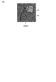
図8は、合成画像I2の一例を示す図である。図8に示すように、合成画像I2は、ROI画像領域R3と静止画領域R4とを含んでいる。ROI画像領域R3は、即時的に生成されるROI画像内のROI領域に対応する。静止画領域R4は、静止画のROI領域以外の画像領域に対応する。すなわち、合成画像I2内のROI画像領域R3は、動画として表示され、静止画領域R4は、静止画として表示される。このように、ROI画像と静止画とを合成表示することにより、ROIの静止画における位置を操作者に容易に把握させつつ、注目するROIのみを即時的に動画として表示させることができる。従ってROI内透視モードにより、透視モードにおける操作性を維持しつつ、透視モードよりも被曝線量を低減することができる。 FIG. 8 is a diagram illustrating an example of the composite image I2. As shown in FIG. 8, the composite image I2 includes an ROI image region R3 and a still image region R4. The ROI image region R3 corresponds to the ROI region in the ROI image generated immediately. The still image area R4 corresponds to an image area other than the ROI area of the still image. That is, the ROI image region R3 in the composite image I2 is displayed as a moving image, and the still image region R4 is displayed as a still image. In this way, by combining and displaying the ROI image and the still image, it is possible to immediately display only the ROI of interest as a moving image while allowing the operator to easily grasp the position of the ROI in the still image. Accordingly, the intra-ROI fluoroscopic mode can reduce the exposure dose as compared with the fluoroscopic mode while maintaining the operability in the fluoroscopic mode.
例えば、画像合成部85は、ROI画像内のROI領域と静止画内のROI領域以外の画像領域とをスーパーインポーズの技術を利用して合成する。これによりROI画像から切り取られたROI領域が静止画に貼りつけられたような合成画像が生成される。
For example, the
なお、上記説明においては、ROI内透視時においては小開口のみで透視が行われるとした。しかしながら、本実施形態はこれに限定されない。例えば、ROI内透視の開始時において、既定の時間だけ大開口で透視が行われても良い。既定の時間は、例えば、1秒等、比較的短い時間に設定されるとよい。ROI内透視の開始時において生成された大開口画像は、表示部9に表示される。既定の時間が経過したことを契機として、上記の通り、駆動制御部6により大開口から小開口により切り替えられ、X線制御部7により小開口で透視が行われる。
In the above description, it is assumed that fluoroscopy is performed with only a small opening during ROI fluoroscopy. However, this embodiment is not limited to this. For example, at the start of fluoroscopy within the ROI, fluoroscopy may be performed with a large opening for a predetermined time. The predetermined time may be set to a relatively short time such as 1 second. A large aperture image generated at the start of ROI fluoroscopy is displayed on the
ROI内透視モードの実行中において、操作者等による操作部12を介した指示によりCアーム22や天板29が可動される場合がある。静止画は過去に生成された画像なので、Cアーム22や天板29が可動されると、ROI画像と静止画とに解剖学的な位置ずれが生じてしまう。位置ずれを起こしているROI画像と静止画との合成画像を観察しても、操作者は、カテーテル等の位置を正しく判断できない。むしろ、位置ずれを起こしているROI画像と静止画との合成画像を表示することにより、操作性が悪化してしまう。
During execution of the ROI fluoroscopic mode, the
本実施形態に係るX線診断装置は、Cアーム22や天板29の空間位置に関する位置情報を利用して、Cアーム22や天板29の可動に伴う上述の不具合を解消する。このために、位置記録部14は、アブレーション手技中におけるCアーム22の空間位置と天板29の空間位置とを記録している。記録のタイミングとしては、一定時間毎にCアーム22の空間位置と天板29の空間位置とを記録してもよいし、Cアーム22や天板29が可動される毎にCアーム22の空間位置と天板29の空間位置とを記録してもよい。空間位置は、時刻と開口サイズ(大開口又は小開口)の識別子とに関連付けて記録される。
The X-ray diagnostic apparatus according to the present embodiment uses the positional information related to the spatial positions of the
位置記録部14に記録された空間位置に関する位置情報を利用して判定部13は、静止画を更新するか否かを判定する。判定部13は、Cアーム22の空間的位置変化と天板29の空間的位置変化とを個別に判定する。なお、判定処理は、所定時間毎に行われても良いし、Cアーム22や天板29が可動される毎に行われても良い。
The
Cアーム22の場合は、以下のように判定される。Cアーム22に関する判定処理において判定部13は、リアルタイムのCアーム22の空間位置と基準時におけるCアーム22の空間位置とを位置記録部14から読み出す。基準時における空間位置は、大開口画像の発生時におけるCアーム22の空間位置に設定される。例えば、基準時における空間位置は、ROI内透視スイッチが踏まれた時点におけるCアーム22の空間位置に設定される。なお、複数回に亘ってROI内透視スイッチが踏まれている場合は、最新の踏まれた時点におけるCアーム22の空間位置が基準時における空間位置に設定される。読み出しが行われると判定部13は、リアルタイムのCアーム22の空間位置と基準時におけるCアーム22の空間位置との差分を算出する。そして判定部13は、算出された差分がCアーム22用の閾値を超えたか否かを判定する。閾値は、操作部12を介して操作者により任意に設定可能である。例えば、閾値は、操作者の位置ずれの許容範囲の最大値等に設定されるとよい。また、ROI画像と静止画との位置ずれを許さないのであれば、閾値は、0に設定されるとよい。
In the case of the
天板29の場合もCアーム22の場合と同様に判定される。天板29に関する判定処理において判定部13は、リアルタイムの天板29の空間位置と基準時における天板29の空間位置とを位置記録部14から読み出す。基準時における空間位置は、大開口画像の発生時における天板29の空間位置に設定される。例えば、基準時における空間位置は、ROI内透視スイッチが踏まれた時点における天板29の空間位置に設定される。なお、複数回に亘ってROI内透視スイッチが踏まれている場合は、最新の踏まれた時点における天板29の空間位置が基準時における空間位置に設定される。読み出しが行われると判定部13は、リアルタイムの天板29の空間位置と基準時における天板29の空間位置との差分を算出する。そして判定部13は、算出された差分が天板29用の閾値を超えたか否かを判定する。閾値は、操作部12を介して操作者により任意に設定可能である。なお、Cアーム22用の閾値と天板29用の閾値とは、個別に設定される。
The case of the
差分が閾値を超えないと判定した場合、判定部13は、静止画を更新する必要はないと判定する。より詳細には、Cアーム22に関する差分と天板29に関する差分との両方が閾値を超えないと判定された場合、静止画を更新する必要はないと判定される。この場合、駆動制御部6は、絞り駆動部4を制御し、開口を小開口に維持する。X線制御部7は、高電圧発生器25を制御し、透視用のX線を発生させ続ける。
If it is determined that the difference does not exceed the threshold, the
差分が閾値を超えたと判定した場合(時刻t3)、判定部13は、静止画を更新すると判定する。より詳細には、Cアーム22に関する差分と天板29に関する差分との少なくとも一方が閾値を超えないと判定された場合、静止画を更新する必要はないと判定される。この場合、駆動制御部6は、絞り駆動部4を制御し、開口を小開口から大開口に自動的に拡大する。X線制御部7は、高電圧発生器25を制御し、透視用のX線をX線管23から繰り返し発生させる。これにより画像生成部81は、大開口画像ISを生成する。この新たな大開口画像ISは、静止画の更新に利用されるので、少なくとも1枚生成されればよい。なお、判定部に13よる判定結果に従って行われる大開口から小開口への切り替えは、操作者によるROI内透視スイッチから透視スイッチへの踏み替え無しに行われる。すなわち、ROI内透視スイッチが踏まれた状態のまま、小開口から大開口への切り替えが行われ、新たな大開口画像ISが生成される。生成された新たな大開口画像ISは、新たな静止画として画像記憶部83に記憶される。
When it is determined that the difference exceeds the threshold (time t3), the
大開口に拡大されてから一定期間経過後(時刻t4)、駆動制御部6は、自動的にROI内透視モードに切り替える。すなわち、駆動制御部6は、絞り駆動部4を制御し、開口を大開口から小開口に自動的に縮小する。X線制御部7は、高電圧発生器25を制御し、透視用のX線を繰り返し発生させる。なお、この所定期間は、少なくとも1枚の大開口画像を生成可能な期間に設定されるとよい。このROI内透視モードの期間、画像生成部81は、ROI画像IRを即時的に繰り返し生成する。ROI画像IRが生成される毎に、画像合成部85は、このROI画像IRと画像記憶部83に新たな静止画として記憶されている大開口画像ISとの合成画像ICを即時的に繰り返し生成する。生成された合成画像ICは、表示部9に動画として即時的に表示される。
After a certain period of time has elapsed since the image was enlarged to the large opening (time t4), the drive control unit 6 automatically switches to the fluoroscopic mode within ROI. That is, the drive control unit 6 controls the diaphragm drive unit 4 to automatically reduce the aperture from a large aperture to a small aperture. The X-ray control unit 7 controls the
なお、上記の説明においては、一定期間経過後に開口が大開口から小開口に自動的に切り替えられるとした。しかしながら、第1実施例は、これに限定されない。例えば、操作者がROI内透視スイッチを踏み直すことを契機として、開口を大開口から小開口に切り替えても良い。これにより、操作者が静止画に適していると判断した大開口画像を合成画像上の静止画に設定することができる。 In the above description, the opening is automatically switched from the large opening to the small opening after a certain period. However, the first embodiment is not limited to this. For example, the opening may be switched from the large opening to the small opening in response to the operator stepping on the ROI fluoroscopic switch. As a result, the large aperture image that the operator determines to be suitable for the still image can be set as the still image on the composite image.
以上により、実施例1に係る動作例の説明を終了する。 This is the end of the description of the operation example according to the first embodiment.
上述のように、実施例1に係るX線診断装置は、静止画生成時におけるCアーム22や天板29の空間位置とリアルタイムのCアーム22や天板29の空間位置との位置ずれ量が閾値を超えた場合、自動的に開口を小開口から大開口に切り替えている。これにより、実施例1に係るX線診断装置は、静止画とROI画像との解剖学的位置ずれが発生することを契機として、自動的に静止画を更新することができ、解剖学的位置ずれ量の少ない合成画像を提供することができる。この際、操作者によるスイッチの踏み替えは必要ない。従って操作者は、スイッチの踏み替えを意識すること無く、静止画を更新することができ、アブレーション手技に集中することができる。
As described above, the X-ray diagnostic apparatus according to the first embodiment has a displacement amount between the spatial position of the
[実施例2]
実施例2に係る位置ずれ指標は、ROI内透視モードにおけるX線のリアルタイムの発生継続時間である。
[Example 2]
The positional deviation index according to the second embodiment is a real-time generation duration of X-rays in the ROI fluoroscopic mode.
図9は、実施例2に係るX線診断装置の構成を示す図である。図9に示すように、実施例2に係るX線診断装置は、本実施形態に係るX線診断装置と比べて、さらにX線発生継続時間計測部15を有している。
FIG. 9 is a diagram illustrating the configuration of the X-ray diagnostic apparatus according to the second embodiment. As shown in FIG. 9, the X-ray diagnostic apparatus according to Example 2 further includes an X-ray generation
X線発生継続時間計測部15は、ROI透視モードの開始時から、X線が継続的に発生されている時間(以下、X線発生継続時間と呼ぶことにする。)を即時的に繰り返し計測する。X線発生継続時間が比較的長い場合、被検体Pが動くことが予想される。換言すれば、X線発生継続時間が比較的長い場合、ROI画像と静止画とに解剖学的位置ずれが生じていると推定可能である。計測されたX線発生継続時間は、判定部13に供給される。
The X-ray generation
判定部13は、ROI画像が生成される毎に、X線発生継続時間に基づいて、静止画を更新するか否かを判定する。判定部13が静止画を更新すると判定した場合、駆動制御部6により開口が小開口から大開口に拡大される。一方、判定部13が静止画を更新しないと判定した場合、駆動制御部6により開口が小開口に維持される。
Each time the ROI image is generated, the
以下、実施例2に係るROI内透視における自動開口制御処理の一例を、図10を参照しながら説明する。図10は、実施例2に係るROI内透視における自動開口制御処理の典型的な流れを模式的に示す図である。なお、実施例1に係るROI内透視における自動開口制御処理と同様の処理内容は、簡略して説明する。 Hereinafter, an example of the automatic opening control process in the ROI fluoroscopy according to the second embodiment will be described with reference to FIG. FIG. 10 is a diagram schematically illustrating a typical flow of the automatic opening control process in the ROI fluoroscopy according to the second embodiment. In addition, the process content similar to the automatic opening control process in the ROI fluoroscopy according to the first embodiment will be briefly described.
まず、時刻t1において操作者が透視スイッチを踏み、駆動制御部6の制御のもとにX線透視が行われる。上述のように、透視モードにおいては、開口は大開口であり、画像生成部81により大開口画像が即時的に繰り返し生成され、表示部9により大開口画像ISが動画として即時的に表示される。
First, at time t <b> 1, the operator steps on the fluoroscopic switch, and X-ray fluoroscopy is performed under the control of the drive control unit 6. As described above, in the perspective mode, the aperture is a large aperture, and the large aperture image is repeatedly generated immediately by the
操作者は、静止画に適した大開口画像が生成されたと判断すると、透視スイッチから足を外し、ROI内透視スイッチを踏む(時刻t2)。ROI内透視スイッチが踏まれた時点に表示部9に表示されている大開口画像は、静止画として表示部9に表示されている。ROI内透視スイッチが踏まれると駆動制御部6は、ROI内透視を開始する。ROI内透視モードの期間、画像生成部81は、ROI画像IRを即時的に繰り返し生成する。ROI画像IRが生成される毎に、画像合成部85は、ROI画像IRと画像記憶部83に静止画として記憶されている大開口画像ISとの合成画像ICを即時的に繰り返し生成する。生成された合成画像ICは、表示部9に動画として即時的に表示される。
When the operator determines that a large aperture image suitable for a still image has been generated, the operator removes his / her foot from the fluoroscopic switch and steps on the ROI intrafluoroscopic switch (time t2). The large aperture image displayed on the
ROI内透視スイッチが踏まれたことを契機として(時刻t2)、X線発生継続時間計測部15は、X線発生継続時間を繰り返し計測する。判定部13は、ROI内透視モードにおいて、計測されたX線発生継続時間が予め設定された所定時間を経過したか否かを繰り返し判定する。所定時間は、操作者により操作部12を介して任意の値に設定可能である。
When the ROI fluoroscopic switch is stepped on (time t2), the X-ray generation
X線発生継続時間が所定時間を超えないと判定した場合、判定部13は、静止画を更新する必要はないと判定する。この場合、駆動制御部6は、絞り駆動部4を制御し、開口を小開口に維持する。X線制御部7は、高電圧発生器25を制御し、透視用のX線を発生させ続ける。
If it is determined that the X-ray generation duration does not exceed the predetermined time, the
X線発生継続時間が所定時間を超えたと判定した場合(時刻t3)、判定部13は、静止画を更新すると判定する。この場合、駆動制御部6は、絞り駆動部4を制御し、開口を小開口から大開口に自動的に拡大する。X線制御部7は、高電圧発生器25を制御し、透視用のX線をX線管23から繰り返し発生させる。これにより画像生成部81は、大開口画像ISを生成する。
When it is determined that the X-ray generation duration has exceeded the predetermined time (time t3), the
大開口に拡大されてから一定期間経過後(時刻t4)、駆動制御部6は、自動的にROI内透視モードに切り替える。すなわち、駆動制御部6は、絞り駆動部4を制御し、開口を大開口から小開口に自動的に縮小する。X線制御部7は、高電圧発生器25を制御し、透視用のX線を繰り返し発生させる。このROI内透視モードの期間、画像生成部81は、ROI画像IRを即時的に繰り返し生成する。ROI画像IRが生成される毎に、画像合成部85は、このROI画像IRと画像記憶部83に新たな静止画として記憶されている大開口画像ISとの合成画像ICを即時的に繰り返し生成する。生成された合成画像ICは、表示部9に動画として即時的に表示される。
After a certain period of time has elapsed since the image was enlarged to the large opening (time t4), the drive control unit 6 automatically switches to the fluoroscopic mode within ROI. That is, the drive control unit 6 controls the diaphragm drive unit 4 to automatically reduce the aperture from a large aperture to a small aperture. The X-ray control unit 7 controls the
以上により、実施例2に係る動作例の説明を終了する。 This is the end of the description of the operation example according to the second embodiment.
上述のように、実施例2に係るX線診断装置は、ROI内透視モードの開始時からのX線発生継続時間が所定時間を超えた場合、自動的に開口を小開口から大開口に切り替えている。これにより、実施例2に係るX線診断装置は、静止画とROI画像との解剖学的位置ずれが発生すると推定されたことを契機として、自動的に静止画を更新することができ、解剖学的位置ずれ量の少ない合成画像を提供することができる。この際、操作者によるスイッチの踏み替えは必要ない。従って操作者は、スイッチの踏み替えを意識すること無く、静止画を更新することができ、アブレーション手技に集中することができる。 As described above, the X-ray diagnostic apparatus according to the second embodiment automatically switches the opening from the small opening to the large opening when the X-ray generation continuation time from the start of the ROI fluoroscopy mode exceeds a predetermined time. ing. As a result, the X-ray diagnostic apparatus according to the second embodiment can automatically update a still image when it is estimated that an anatomical positional deviation between the still image and the ROI image occurs. It is possible to provide a composite image with a small amount of geometric displacement. At this time, the operator does not need to switch the switch. Therefore, the operator can update the still image without being conscious of stepping on the switch, and can concentrate on the ablation technique.
[実施例3]
実施例3に係る位置ずれ指標は、ROI内透視モードにおけるX線のリアルタイムの非発生継続時間である。
[Example 3]
The misalignment index according to the third embodiment is a real-time non-occurrence duration time of X-rays in the ROI fluoroscopic mode.
図11は、実施例3に係るX線診断装置の構成を示す図である。図11に示すように、実施例3に係るX線診断装置は、本実施形態に係るX線診断装置と比べて、さらにX線非発生継続時間計測部16を有している。
FIG. 11 is a diagram illustrating the configuration of the X-ray diagnostic apparatus according to the third embodiment. As shown in FIG. 11, the X-ray diagnostic apparatus according to Example 3 further includes an X-ray non-occurrence
X線非発生継続時間計測部16は、ROI内透視モードにおいてX線の発生が停止された時点から、X線が継続的に発生されていない時間(以下、X線非発生継続時間と呼ぶことにする。)を即時的に繰り返し計測する。X線非発生継続時間が比較的長い場合、被検体Pが動いたり、Cアーム22や天板29が可動されていることが予想される。換言すれば、X線非発生継続時間が比較的長い場合、ROI画像と静止画とに解剖学的位置ずれが生じていると推定可能である。計測されたX線非発生継続時間は、判定部13に供給される。
The X-ray non-occurrence
判定部13は、X線非発生継続時間に基づいて、静止画を更新するか否かを判定する。判定部13が静止画を更新すると判定した場合、駆動制御部6により開口が小開口から大開口に拡大される。一方、判定部13が静止画を更新しないと判定した場合、駆動制御部6により開口が小開口に維持される。
The
以下、実施例3に係るROI内透視における自動開口制御処理の一例を、図12を参照しながら説明する。図12は、実施例3に係るROI内透視における自動開口制御処理の典型的な流れを模式的に示す図である。なお、実施例1に係るROI内透視における自動開口制御処理と同様の処理内容は、簡略して説明する。 Hereinafter, an example of the automatic opening control process in the ROI fluoroscopy according to the third embodiment will be described with reference to FIG. FIG. 12 is a diagram schematically illustrating a typical flow of the automatic opening control process in the ROI fluoroscopy according to the third embodiment. In addition, the process content similar to the automatic opening control process in the ROI fluoroscopy according to the first embodiment will be briefly described.
まず、時刻t1において操作者が透視スイッチを踏み、駆動制御部6の制御のもとにX線透視が行われる。上述のように、透視モードにおいては、開口は大開口であり、画像生成部81により大開口画像が即時的に繰り返し生成され、表示部9により大開口画像ISが動画として即時的に表示される。
First, at time t <b> 1, the operator steps on the fluoroscopic switch, and X-ray fluoroscopy is performed under the control of the drive control unit 6. As described above, in the perspective mode, the aperture is a large aperture, and the large aperture image is repeatedly generated immediately by the
操作者は、静止画に適した大開口画像が生成されたと判断すると、透視スイッチから足を外し、ROI内透視スイッチを踏む(時刻t2)。ROI内透視スイッチが踏まれた時点に表示部9に表示されている大開口画像は、静止画として表示部9に表示されている。ROI内透視スイッチが踏まれると駆動制御部6は、ROI内透視を開始する。ROI内透視モードの期間、画像生成部81は、ROI画像IRを即時的に繰り返し生成する。ROI画像IRが生成される毎に、画像合成部85は、ROI画像IRと画像記憶部83に静止画として記憶されている大開口画像ISとの合成画像ICを即時的に繰り返し生成する。生成された合成画像ICは、表示部9に動画として即時的に表示される。
When the operator determines that a large aperture image suitable for a still image has been generated, the operator removes his / her foot from the fluoroscopic switch and steps on the ROI intrafluoroscopic switch (time t2). The large aperture image displayed on the
ROI内透視時においてX線を停止する場合がある。例えば、操作者がフットスイッチ部11の全てのスイッチから足を外した場合、X線制御部7は、高電圧発生器25を制御し、X線管23からのX線の発生を停止する。すなわち、ROI透視が停止される。ROI内透視が停止されたことを契機として(時刻t2´)、X線非発生継続時間計測部16は、X線非発生継続時間を繰り返し計測する。判定部13は、X線停止期間において、計測されたX線非発生継続時間が予め設定された所定時間を経過したか否かを繰り返し判定する。所定時間は、操作者により操作部12を介して任意の値に設定可能である。
There is a case where X-rays are stopped during fluoroscopy within the ROI. For example, when the operator removes his / her foot from all the switches of the
X線非発生継続時間が所定時間を超えないと判定した場合、判定部13は、静止画を更新する必要はないと判定する。この場合、駆動制御部6は、絞り駆動部4を制御し、開口を小開口に維持する。X線制御部7は、高電圧発生器25を制御し、透視用のX線を発生させ続ける。
When it is determined that the X-ray non-occurrence continuation time does not exceed the predetermined time, the
X線非発生継続時間が所定時間を超えたと判定した場合(時刻t3)、判定部13は、静止画を更新すると判定する。この場合、駆動制御部6は、絞り駆動部4を制御し、開口を小開口から大開口に自動的に拡大する。X線制御部7は、高電圧発生器25を制御し、透視用のX線をX線管23から繰り返し発生させる。これにより画像生成部81は、大開口画像ISを生成する。
When it is determined that the X-ray non-occurrence continuation time exceeds the predetermined time (time t3), the
大開口に拡大されてから一定期間経過後(時刻t4)、駆動制御部6は、自動的にROI内透視モードに切り替える。すなわち、駆動制御部6は、絞り駆動部4を制御し、開口を大開口から小開口に自動的に縮小する。X線制御部7は、高電圧発生器25を制御し、透視用のX線を繰り返し発生させる。このROI内透視モードの期間、画像生成部81は、ROI画像IRを即時的に繰り返し生成する。ROI画像IRが生成される毎に、画像合成部85は、このROI画像IRと画像記憶部83に新たな静止画として記憶されている大開口画像ISとの合成画像ICを即時的に繰り返し生成する。生成された合成画像ICは、表示部9に動画として即時的に表示される。
After a certain period of time has elapsed since the image was enlarged to the large opening (time t4), the drive control unit 6 automatically switches to the fluoroscopic mode within ROI. That is, the drive control unit 6 controls the diaphragm drive unit 4 to automatically reduce the aperture from a large aperture to a small aperture. The X-ray control unit 7 controls the
以上により、実施例3に係る動作例の説明を終了する。 This is the end of the description of the operation example according to the third embodiment.
上述のように、実施例3に係るX線診断装置は、ROI内透視中にX線が停止された場合、X線の停止時からのX線非発生継続時間が所定時間を超えた場合、自動的に開口を小開口から大開口に切り替えている。これにより、実施例3に係るX線診断装置は、静止画とROI画像との解剖学的位置ずれが発生すると推定されたことを契機として、自動的に静止画を更新することができ、解剖学的位置ずれ量の少ない合成画像を提供することができる。この際、操作者によるスイッチの踏み替えは必要ない。従って操作者は、スイッチの踏み替えを意識すること無く、静止画を更新することができ、アブレーション手技に集中することができる。 As described above, when the X-ray diagnosis apparatus according to the third embodiment stops X-rays during ROI fluoroscopy, when the X-ray non-occurrence continuation time from the X-ray stop time exceeds a predetermined time, The opening is automatically switched from a small opening to a large opening. As a result, the X-ray diagnostic apparatus according to the third embodiment can automatically update a still image when it is estimated that an anatomical positional shift between the still image and the ROI image occurs. It is possible to provide a composite image with a small amount of geometric displacement. At this time, the operator does not need to switch the switch. Therefore, the operator can update the still image without being conscious of stepping on the switch, and can concentrate on the ablation technique.
[実施例4]
実施例4に係る位置ずれ指標は、ROI内透視モードのONに関する情報とOFFに関する情報とである。
[Example 4]
The misregistration index according to the fourth embodiment is information related to ON and OFF information related to the ROI fluoroscopic mode.
実施例4に係るX線診断装置の構成は、図1に示す構成と同一である。 The configuration of the X-ray diagnostic apparatus according to the fourth embodiment is the same as that shown in FIG.
上述のように、フットスイッチ部11は、ROI内透視スイッチを装備している。ROI内透視スイッチが踏まれている期間、ROI内透視がONに設定され、ROI内透視スイッチが踏まれていない期間、ROI内透視がOFFに設定される。すなわち、ROI内透視スイッチが踏まれることを契機としてROI内透視がONに切り替えられる。ROI内透視スイッチが踏まれることを契機としてON信号がフットスイッチ部11からシステム制御部1を介して駆動制御部6に供給される。ON信号が供給された場合、駆動制御部6は、上述のようにROI内透視を実行する。ROI内透視スイッチが外されたことを契機としてOFF信号がフットスイッチ部11からシステム制御部1を介して駆動制御部6に供給される。OFF信号が供給された場合、駆動制御部6は、上述のようにROI内透視を中断する。また、ON信号とOFF信号とは、システム制御部1を介して判定部13に供給される。
As described above, the
判定部13は、ROI内透視モードの切り替えに従って静止画を更新するか否かを判定する。より詳細には、判定部13は、ROI内透視モードに切り替える毎に静止画を更新すると判定し、それ以外の場合、静止画を更新しないと判定する。判定部13が静止画を更新すると判定した場合、駆動制御部6により開口が小開口から大開口に拡大される。一方、判定部13が静止画を更新しないと判定した場合、駆動制御部6により開口が小開口に維持される。
The
以下、実施例4に係るROI内透視における自動開口制御処理の一例を、図13を参照しながら説明する。図13は、実施例4に係るROI内透視における自動開口制御処理の典型的な流れを模式的に示す図である。なお、実施例1に係るROI内透視における自動開口制御処理と同様の処理内容は、簡略して説明する。 Hereinafter, an example of the automatic opening control process in the ROI fluoroscopy according to the fourth embodiment will be described with reference to FIG. FIG. 13 is a diagram schematically illustrating a typical flow of the automatic opening control process in the ROI fluoroscopy according to the fourth embodiment. In addition, the process content similar to the automatic opening control process in the ROI fluoroscopy according to the first embodiment will be briefly described.
まず、時刻t1において操作者が透視スイッチを踏み、駆動制御部6の制御のもとにX線透視が行われる。上述のように、透視モードにおいては、開口は大開口であり、画像生成部81により大開口画像が即時的に繰り返し生成され、表示部9により大開口画像ISが動画として即時的に表示される。透視スイッチが踏まれている期間、ROI内透視スイッチは踏まれていないので、フットスイッチ部11から判定部13にOFF信号が供給される。OFF信号が供給されている場合、判定部13は、静止画を更新しないと判定する。
First, at time t <b> 1, the operator steps on the fluoroscopic switch, and X-ray fluoroscopy is performed under the control of the drive control unit 6. As described above, in the perspective mode, the aperture is a large aperture, and the large aperture image is repeatedly generated immediately by the
操作者は、静止画に適した大開口画像が生成されたと判断すると、透視スイッチから足を外し、ROI内透視スイッチを踏む(時刻t2)。ROI内透視スイッチが踏まれた時点に表示部9に表示されている大開口画像は、静止画として表示部9に表示されている。ROI内透視スイッチが踏まれると駆動制御部6は、ROI内透視を開始する。ROI内透視に切り替えられることを契機として駆動制御部6は、絞り駆動部4を制御し、開口を大開口から小開口に自動的に縮小する。X線制御部7は、高電圧発生器25を制御し、透視用のX線をX線管23から繰り返し発生させる。これによりROI内透視モードの期間、画像生成部81は、ROI画像IRを即時的に繰り返し生成する。ROI画像IRが生成される毎に、画像合成部85は、ROI画像IRと画像記憶部83に静止画として記憶されている大開口画像ISとの合成画像ICを即時的に繰り返し生成する。生成された合成画像ICは、表示部9に動画として即時的に表示される。
When the operator determines that a large aperture image suitable for a still image has been generated, the operator removes his / her foot from the fluoroscopic switch and steps on the ROI intrafluoroscopic switch (time t2). The large aperture image displayed on the
上述のように、ROI内透視時において被検体Pが動いたり、Cアーム22や天板29が動いたりする場合がある。この場合、ROI画像と静止画とに解剖学的位置ずれが生ずることとなる。この場合、操作者は、ROI内透視スイッチを踏みなおす(t3)。ROI内透視スイッチを踏み直すことによりフットスイッチ部11から判定部13にON信号が供給される。ON信号が供給されることを契機として判定部13は、静止画を更新すると判定する。この場合、駆動制御部6は、まず、絞り駆動部4を制御し、開口を小開口から大開口に自動的に拡大する。X線制御部7は、高電圧発生器25を制御し、透視用のX線をX線管23から繰り返し発生させる。これにより画像生成部81は、大開口画像ISを生成する。
As described above, the subject P may move or the C-
大開口に拡大されてから一定期間経過後(時刻t4)、駆動制御部6は、自動的にROI内透視モードに切り替える。この一定期間は、少なくとも1フレーム分の大開口画像ISを生成可能な時間に設定される。すなわち、駆動制御部6は、絞り駆動部4を制御し、開口を大開口から小開口に自動的に縮小する。X線制御部7は、高電圧発生器25を制御し、透視用のX線を繰り返し発生させる。このROI内透視モードの期間、画像生成部81は、ROI画像IRを即時的に繰り返し生成する。ROI画像IRが生成される毎に、画像合成部85は、このROI画像IRと画像記憶部83に新たな静止画として記憶されている大開口画像ISとの合成画像ICを即時的に繰り返し生成する。生成された合成画像ICは、表示部9に動画として即時的に表示される。
After a certain period of time has elapsed since the image was enlarged to the large opening (time t4), the drive control unit 6 automatically switches to the fluoroscopic mode within ROI. This fixed period is set to a time during which a large aperture image IS for at least one frame can be generated. That is, the drive control unit 6 controls the diaphragm drive unit 4 to automatically reduce the aperture from a large aperture to a small aperture. The X-ray control unit 7 controls the
以上により、実施例4に係る動作例の説明を終了する。 This is the end of the description of the operation example according to the fourth embodiment.
上述のように、実施例4に係るX線診断装置は、ROI内透視スイッチが踏まれた場合、静止画を自動的に更新する。これにより、実施例4に係るX線診断装置は、静止画とROI画像との解剖学的位置ずれが発生すると推定されたことを契機として、自動的に静止画を更新することができ、解剖学的位置ずれ量の少ない合成画像を提供することができる。 As described above, the X-ray diagnostic apparatus according to the fourth embodiment automatically updates the still image when the ROI intrafluoroscopic switch is stepped on. As a result, the X-ray diagnostic apparatus according to the fourth embodiment can automatically update a still image when it is estimated that an anatomical positional shift between the still image and the ROI image occurs. It is possible to provide a composite image with a small amount of geometric displacement.
[効果]
かくして、本実施形態によれば、手技効率の向上を可能とするX線診断装置を提供することが可能となる。
[effect]
Thus, according to the present embodiment, it is possible to provide an X-ray diagnostic apparatus that can improve procedure efficiency.
本発明のいくつかの実施形態を説明したが、これらの実施形態は、例として提示したものであり、発明の範囲を限定することは意図していない。これら新規な実施形態は、その他の様々な形態で実施されることが可能であり、発明の要旨を逸脱しない範囲で、種々の省略、置き換え、変更を行うことができる。これら実施形態やその変形は、発明の範囲や要旨に含まれるとともに、特許請求の範囲に記載された発明とその均等の範囲に含まれるものである。 Although several embodiments of the present invention have been described, these embodiments are presented by way of example and are not intended to limit the scope of the invention. These novel embodiments can be implemented in various other forms, and various omissions, replacements, and changes can be made without departing from the scope of the invention. These embodiments and modifications thereof are included in the scope and gist of the invention, and are included in the invention described in the claims and the equivalents thereof.
1…システム制御部、2…撮像機構、3…Cアーム駆動部、4…絞り駆動部、5…寝台駆動部、6…駆動制御部、7…X線制御部、8…画像処理部、9…表示部、10…表示制御部、11…フットスイッチ部、12…操作部、13…判定部、14…位置記録部、15…X線発生継続時間計測部、16…X線非発生継続時間計測部、21…Cアームホルダ、22…Cアーム、23…X線管、24…X線検出器、25…高電圧発生器、26…X線絞り器、27…寝台、28…脚部、29…天板、81…画像生成部、83…画像記憶部、85…画像合成部
DESCRIPTION OF SYMBOLS 1 ... System control part, 2 ... Imaging mechanism, 3 ... C arm drive part, 4 ... Diaphragm drive part, 5 ... Bed drive part, 6 ... Drive control part, 7 ... X-ray control part, 8 ... Image processing part, 9
Claims (4)
前記X線管から発生され被検体を透過したX線を検出するX線検出器と、
前記X線管からのX線の照射野を限定するための開口可変の絞り機構と、
前記絞り機構の開口が第1の開口である期間において前記X線検出器の出力に基づいて第1のX線画像を生成し、前記絞り機構の開口が前記第1の開口よりも狭い第2の開口である期間において前記X線検出器の出力に基づいて第2のX線画像を繰り返し生成する画像生成部と、
前記第2のX線画像が発生される毎に、前記繰り返し生成される第2のX線画像のうちの最新の第2のX線画像を動画として前記第1のX線画像とともに表示する表示部と、
第1のX線画像を繰り返し生成させるためのX線の照射を実行させる操作を受け付ける第1の入力スイッチと、第2のX線画像を繰り返し生成させるためのX線の照射を実行させる操作を受け付ける第2の入力スイッチとを有するフットスイッチ部と、
前記第2の入力スイッチを踏む操作が受け付けられると、前記第1のX線画像を再度取得するために、前記絞り機構を制御して前記絞り機構の開口を前記第2の開口から前記第1の開口に拡大させて前記第1のX線画像を取得した後、自動的に前記絞り機構を前記第2の開口に縮小させる制御を行い、前記第2の入力スイッチを踏む操作が終了するまで、前記絞り機構の開口を前記第2の開口にした状態で前記第2のX線画像を繰り返し生成させる制御を行う制御部と、
を具備するX線診断装置。 An X-ray tube that generates X-rays;
An X-ray detector for detecting X-rays generated from the X-ray tube and transmitted through the subject;
A variable aperture mechanism for limiting the X-ray irradiation field from the X-ray tube;
A first X-ray image is generated based on the output of the X-ray detector during a period in which the aperture of the aperture mechanism is the first aperture, and the aperture of the aperture mechanism is narrower than the first aperture. An image generation unit that repeatedly generates a second X-ray image based on the output of the X-ray detector in a period of the aperture
A display that displays the latest second X-ray image of the repeatedly generated second X-ray image as a moving image together with the first X-ray image every time the second X-ray image is generated And
A first input switch for accepting the operation to perform the irradiation of X-rays for generating repeatedly a first X-ray images, an operation to perform the X-ray irradiation for repeatedly generating a second X-ray image A foot switch unit having a second input switch for receiving;
When an operation of stepping on the second input switch is accepted, in order to acquire the first X-ray image again, the aperture mechanism is controlled to move the aperture mechanism from the second aperture to the first aperture. Until the first X-ray image is obtained by enlarging the first aperture, and then the control of automatically reducing the aperture mechanism to the second aperture is performed until the operation of stepping on the second input switch is completed. A control unit that performs control to repeatedly generate the second X-ray image in a state where the aperture of the aperture mechanism is the second aperture;
An X-ray diagnostic apparatus comprising:
前記所定時間は、前記第1のX線画像が生成される前記所定の時間間隔より長い請求項3に記載のX線診断装置。 The first X-ray image is repeatedly generated at a predetermined time interval based on the output of the X-ray detector in a period in which the aperture of the aperture mechanism is the first aperture,
The X-ray diagnostic apparatus according to claim 3, wherein the predetermined time is longer than the predetermined time interval at which the first X-ray image is generated.
Priority Applications (1)
| Application Number | Priority Date | Filing Date | Title |
|---|---|---|---|
| JP2012191623A JP6157818B2 (en) | 2011-10-07 | 2012-08-31 | X-ray diagnostic equipment |
Applications Claiming Priority (3)
| Application Number | Priority Date | Filing Date | Title |
|---|---|---|---|
| JP2011223305 | 2011-10-07 | ||
| JP2011223305 | 2011-10-07 | ||
| JP2012191623A JP6157818B2 (en) | 2011-10-07 | 2012-08-31 | X-ray diagnostic equipment |
Publications (3)
| Publication Number | Publication Date |
|---|---|
| JP2013090912A JP2013090912A (en) | 2013-05-16 |
| JP2013090912A5 JP2013090912A5 (en) | 2015-08-27 |
| JP6157818B2 true JP6157818B2 (en) | 2017-07-05 |
Family
ID=48043524
Family Applications (1)
| Application Number | Title | Priority Date | Filing Date |
|---|---|---|---|
| JP2012191623A Active JP6157818B2 (en) | 2011-10-07 | 2012-08-31 | X-ray diagnostic equipment |
Country Status (4)
| Country | Link |
|---|---|
| US (2) | US8903041B2 (en) |
| JP (1) | JP6157818B2 (en) |
| CN (1) | CN103153191B (en) |
| WO (1) | WO2013051356A1 (en) |
Families Citing this family (18)
| Publication number | Priority date | Publication date | Assignee | Title |
|---|---|---|---|---|
| JP5954762B2 (en) * | 2011-11-29 | 2016-07-20 | 東芝メディカルシステムズ株式会社 | X-ray diagnostic imaging equipment |
| EP2680677A1 (en) * | 2012-06-25 | 2014-01-01 | General Electric Company | Image display method |
| EP2941774B1 (en) * | 2013-01-01 | 2019-07-24 | ControlRAD Systems Inc. | X-ray reduction system |
| EP2991555B1 (en) * | 2013-04-03 | 2018-10-17 | Koninklijke Philips N.V. | Interventional x-ray system |
| JP6046250B2 (en) * | 2013-06-19 | 2016-12-14 | 株式会社トプコン | Ophthalmic photographing apparatus and ophthalmic image display apparatus |
| CN103800021B (en) * | 2014-01-17 | 2017-07-18 | 北京东方惠尔图像技术有限公司 | X-ray out-phase pulse biplane synchronization real-time imaging devices and imaging method |
| KR102233319B1 (en) * | 2014-01-20 | 2021-03-29 | 삼성전자주식회사 | A method for tracing a region of interest, a radiation imaging apparatus, a method for controlling the radiation imaging apparatus and a radiographic method |
| JP2016034451A (en) * | 2014-08-04 | 2016-03-17 | 株式会社東芝 | X-ray diagnostic apparatus |
| KR20160089688A (en) * | 2015-01-20 | 2016-07-28 | 삼성전자주식회사 | X-ray image apparatus and control method for same |
| US10556129B2 (en) * | 2015-10-02 | 2020-02-11 | Varian Medical Systems, Inc. | Systems and methods for treating a skin condition using radiation |
| US10405820B2 (en) * | 2016-05-26 | 2019-09-10 | Carestream Health, Inc. | Real-time image processing for fluoroscopic imaging |
| CN106841242B (en) * | 2017-01-23 | 2019-02-22 | 刘智慧 | Detection method and device |
| US11369330B2 (en) | 2017-05-16 | 2022-06-28 | Canon Medical Systems Corporation | X-ray diagnosis apparatus |
| JP7339722B2 (en) * | 2017-05-25 | 2023-09-06 | キヤノンメディカルシステムズ株式会社 | X-ray diagnostic device and foot switch |
| DE112018005199T5 (en) * | 2017-11-02 | 2020-06-18 | Siemens Healthcare Gmbh | Creation of composite images based on live images |
| US11083431B2 (en) * | 2018-02-23 | 2021-08-10 | Shimadzu Corporation | Radiation fluoroscopy imaging apparatus |
| JP7237453B2 (en) * | 2018-04-09 | 2023-03-13 | キヤノンメディカルシステムズ株式会社 | X-ray diagnostic equipment |
| US11298098B2 (en) | 2018-09-25 | 2022-04-12 | Canon Medical Systems Corporation | X-ray diagnosis apparatus and image processing method |
Family Cites Families (13)
| Publication number | Priority date | Publication date | Assignee | Title |
|---|---|---|---|---|
| JPH08164130A (en) * | 1994-12-13 | 1996-06-25 | Shimadzu Corp | X-ray radioscopic system |
| JPH10234714A (en) * | 1997-02-21 | 1998-09-08 | Toshiba Iyou Syst Eng Kk | X-ray radiographic device |
| JPH1147122A (en) * | 1997-08-01 | 1999-02-23 | Hitachi Medical Corp | X-ray image diagnostic device |
| DE10119105A1 (en) * | 2001-04-19 | 2002-10-24 | Philips Corp Intellectual Pty | Method for reconstruction of 2-D and 3-D images from X-ray conical projection data that combines inner examination area high resolution projections with outer lower resolution projections for optimum imaging |
| JP2003000584A (en) * | 2001-06-11 | 2003-01-07 | Ge Medical Systems Global Technology Co Llc | X-ray ct scan system, conveying apparatus and control method therefor |
| JP4068369B2 (en) * | 2002-03-15 | 2008-03-26 | 株式会社東芝 | X-ray diagnostic imaging equipment |
| CN1829476B (en) * | 2003-07-30 | 2012-08-01 | 皇家飞利浦电子股份有限公司 | X-ray unit having an automatically adjustable collimator |
| CN100551331C (en) * | 2004-07-13 | 2009-10-21 | 株式会社日立医药 | The radioscopic image diagnostic equipment |
| WO2006006601A1 (en) * | 2004-07-13 | 2006-01-19 | Hitachi Medical Corporation | X-ray image diagnosing system |
| JP5017004B2 (en) * | 2007-07-20 | 2012-09-05 | キヤノン株式会社 | Radiation image acquisition apparatus and method |
| DE102008050844B4 (en) * | 2008-10-08 | 2016-04-21 | Siemens Aktiengesellschaft | Device and method for localizing a tissue change for a biopsy |
| JP5405081B2 (en) | 2008-10-10 | 2014-02-05 | 株式会社東芝 | 3D image processing apparatus and X-ray diagnostic apparatus |
| CN101897594B (en) | 2009-05-26 | 2012-11-28 | 株式会社东芝 | X-ray CT apparatus and a method for detecting magnetic pole position thereof |
-
2012
- 2012-08-31 CN CN201280002377.XA patent/CN103153191B/en active Active
- 2012-08-31 JP JP2012191623A patent/JP6157818B2/en active Active
- 2012-08-31 WO PCT/JP2012/072203 patent/WO2013051356A1/en active Application Filing
- 2012-12-11 US US13/710,911 patent/US8903041B2/en active Active
-
2014
- 2014-10-22 US US14/521,037 patent/US9131908B2/en active Active
Also Published As
| Publication number | Publication date |
|---|---|
| WO2013051356A1 (en) | 2013-04-11 |
| US20150078524A1 (en) | 2015-03-19 |
| CN103153191A (en) | 2013-06-12 |
| JP2013090912A (en) | 2013-05-16 |
| US20130101084A1 (en) | 2013-04-25 |
| US9131908B2 (en) | 2015-09-15 |
| US8903041B2 (en) | 2014-12-02 |
| CN103153191B (en) | 2015-07-15 |
Similar Documents
| Publication | Publication Date | Title |
|---|---|---|
| JP6157818B2 (en) | X-ray diagnostic equipment | |
| US9384545B2 (en) | X-ray image diagnosis apparatus | |
| WO2014042202A1 (en) | Diagnostic x-ray apparatus | |
| JP2011139761A (en) | X-ray diagnostic apparatus, and controlling method for x-ray diagnostic apparatus | |
| WO2014054442A1 (en) | X-ray diagnostic device and x-ray diagnostic device control method | |
| WO2013175712A1 (en) | X-ray diagnostic device and x-ray diagnostic support method | |
| JP5500931B2 (en) | X-ray diagnostic imaging equipment | |
| JP2014144053A (en) | X-ray diagnostic apparatus | |
| JP5873256B2 (en) | X-ray diagnostic equipment | |
| JP4515585B2 (en) | Medical device | |
| JP2022174736A (en) | Panoramic x-ray imaging apparatus | |
| JP7242191B2 (en) | X-ray diagnostic equipment | |
| JP2005245761A (en) | X-ray diagnostic apparatus | |
| JP2011217904A (en) | X-ray diagnostic apparatus | |
| JP2009291531A (en) | X-ray diagnostic apparatus | |
| JP2010220838A (en) | Radiographic apparatus | |
| JP2006325956A (en) | Image diagnosing device | |
| WO2013175977A1 (en) | Diagnostic x-ray apparatus | |
| US20150374325A1 (en) | X-ray diagnostic apparatus | |
| US20220160320A1 (en) | X-ray diagnostic apparatus and control method thereof | |
| JP2001238872A (en) | X-ray equipment | |
| JP6162391B2 (en) | X-ray diagnostic equipment | |
| JP2016013303A (en) | Medical image diagnostic apparatus | |
| JP2016041091A (en) | X-ray diagnostic apparatus | |
| JP5752288B2 (en) | X-ray diagnostic imaging equipment |
Legal Events
| Date | Code | Title | Description |
|---|---|---|---|
| RD04 | Notification of resignation of power of attorney |
Free format text: JAPANESE INTERMEDIATE CODE: A7424 Effective date: 20131219 |
|
| RD04 | Notification of resignation of power of attorney |
Free format text: JAPANESE INTERMEDIATE CODE: A7424 Effective date: 20131226 |
|
| RD04 | Notification of resignation of power of attorney |
Free format text: JAPANESE INTERMEDIATE CODE: A7424 Effective date: 20140109 |
|
| A521 | Request for written amendment filed |
Free format text: JAPANESE INTERMEDIATE CODE: A523 Effective date: 20150708 |
|
| A621 | Written request for application examination |
Free format text: JAPANESE INTERMEDIATE CODE: A621 Effective date: 20150708 |
|
| A711 | Notification of change in applicant |
Free format text: JAPANESE INTERMEDIATE CODE: A711 Effective date: 20160511 |
|
| A977 | Report on retrieval |
Free format text: JAPANESE INTERMEDIATE CODE: A971007 Effective date: 20160520 |
|
| A131 | Notification of reasons for refusal |
Free format text: JAPANESE INTERMEDIATE CODE: A131 Effective date: 20160524 |
|
| A521 | Request for written amendment filed |
Free format text: JAPANESE INTERMEDIATE CODE: A523 Effective date: 20160725 |
|
| A02 | Decision of refusal |
Free format text: JAPANESE INTERMEDIATE CODE: A02 Effective date: 20161220 |
|
| A521 | Request for written amendment filed |
Free format text: JAPANESE INTERMEDIATE CODE: A523 Effective date: 20170321 |
|
| A911 | Transfer to examiner for re-examination before appeal (zenchi) |
Free format text: JAPANESE INTERMEDIATE CODE: A911 Effective date: 20170328 |
|
| TRDD | Decision of grant or rejection written | ||
| A01 | Written decision to grant a patent or to grant a registration (utility model) |
Free format text: JAPANESE INTERMEDIATE CODE: A01 Effective date: 20170509 |
|
| A61 | First payment of annual fees (during grant procedure) |
Free format text: JAPANESE INTERMEDIATE CODE: A61 Effective date: 20170607 |
|
| R150 | Certificate of patent or registration of utility model |
Ref document number: 6157818 Country of ref document: JP Free format text: JAPANESE INTERMEDIATE CODE: R150 |
|
| S533 | Written request for registration of change of name |
Free format text: JAPANESE INTERMEDIATE CODE: R313533 |
|
| R350 | Written notification of registration of transfer |
Free format text: JAPANESE INTERMEDIATE CODE: R350 |