JP6152965B2 - ELEVATOR DEVICE, ITS CONTROL METHOD, AND ELEVATOR REMOTE STATE STATE DETERMINATION DEVICE - Google Patents
ELEVATOR DEVICE, ITS CONTROL METHOD, AND ELEVATOR REMOTE STATE STATE DETERMINATION DEVICE Download PDFInfo
- Publication number
- JP6152965B2 JP6152965B2 JP2016559371A JP2016559371A JP6152965B2 JP 6152965 B2 JP6152965 B2 JP 6152965B2 JP 2016559371 A JP2016559371 A JP 2016559371A JP 2016559371 A JP2016559371 A JP 2016559371A JP 6152965 B2 JP6152965 B2 JP 6152965B2
- Authority
- JP
- Japan
- Prior art keywords
- slip
- information
- car
- drive sheave
- elevator
- Prior art date
- Legal status (The legal status is an assumption and is not a legal conclusion. Google has not performed a legal analysis and makes no representation as to the accuracy of the status listed.)
- Active
Links
Images


Classifications
-
- B—PERFORMING OPERATIONS; TRANSPORTING
- B66—HOISTING; LIFTING; HAULING
- B66B—ELEVATORS; ESCALATORS OR MOVING WALKWAYS
- B66B5/00—Applications of checking, fault-correcting, or safety devices in elevators
- B66B5/0006—Monitoring devices or performance analysers
- B66B5/0037—Performance analysers
Description
この発明は、トラクション方式のエレベータ装置、その制御方法、及びエレベータ装置の状態を遠隔地で判定するエレベータ用遠隔地状態判定装置に関するものである。 The present invention relates to a traction type elevator apparatus, a control method therefor, and an elevator remote area state determination apparatus that determines the state of an elevator apparatus at a remote area.
従来のトラクション方式のエレベータ装置では、複数の被検出板が昇降路内の各階床の高さに設置されている。かごには、各階床の被検出板を検出する被検出板検出器が設けられている。回転検出器は、巻上機モータの回転に応じた信号を制御装置に出力する。制御装置は、基準位置から被検出板が検出されるまでの間に回転検出器から出力された信号に基づいて、階高データを算出する。また、制御装置は、基準となる基準階高データと、算出した階高データとの差分を算出し、その差分と判定値との比較結果に基づいて、かごの制御を変更する(例えば、特許文献1参照)。 In a conventional traction type elevator apparatus, a plurality of detection plates are installed at the height of each floor in the hoistway. The car is provided with a detected plate detector for detecting the detected plate on each floor. The rotation detector outputs a signal corresponding to the rotation of the hoist motor to the control device. The control device calculates the floor height data based on a signal output from the rotation detector until the detected plate is detected from the reference position. Further, the control device calculates a difference between the reference floor height data serving as a reference and the calculated floor height data, and changes the control of the car based on the comparison result between the difference and the determination value (for example, patent Reference 1).
上記のような従来のエレベータ装置では、被検出板が各階床のかごの停止位置に合わせて設置されているため、特定階に設置された被検出板を検出してから特定階に隣接する階に設置された被検出板を検出するまでの間に駆動シーブと懸架体との間に生じた合計の滑り距離(以下、滑り量)を検出することができる。しかし、かごの階間走行中にも時々刻々と変化して生じる滑り(以下、滑り)が階間のどこでどのように生じているのかを把握することはできなかった。従って、駆動シーブと懸架体との間のトラクション能力の低下により局所的に生じた駆動シーブと懸架体との間の滑りを、正常なトラクション状態で全域的に生じる微小な滑りと区別することができなかった。 In the conventional elevator apparatus as described above, since the detected plate is installed in accordance with the stop position of the car on each floor, the floor adjacent to the specific floor is detected after detecting the detected plate installed on the specific floor. It is possible to detect the total slip distance (hereinafter referred to as slip amount) generated between the drive sheave and the suspension body until the detection plate installed on the head is detected. However, it was not possible to grasp where and how slips (hereinafter referred to as slips), which are generated by changing every moment while the car is traveling between floors, occur between the floors. Therefore, it is possible to distinguish the slip between the drive sheave and the suspension caused locally due to the decrease in the traction capability between the drive sheave and the suspension from the minute slip that occurs in the whole area in a normal traction state. could not.
この発明は、上記のような課題を解決するためになされたものであり、簡単な構成により、駆動シーブと懸架体との間の局所的な滑りの発生を検出することができるエレベータ装置、その制御方法、及びエレベータ用遠隔地状態判定装置を得ることを目的とする。 The present invention has been made to solve the above-described problems, and an elevator apparatus capable of detecting the occurrence of local slip between the drive sheave and the suspension body with a simple configuration. It is an object of the present invention to obtain a control method and an elevator remote location state determination device.
この発明に係るエレベータ装置は、駆動シーブと、駆動シーブを回転させる巻上機モータとを有する巻上機、駆動シーブに巻き掛けられている懸架体、懸架体により昇降路内に吊り下げられており、巻上機モータの駆動力により昇降するかご及び釣合おもり、かごが昇降路内の検出位置にあることを検出する位置センサ、駆動シーブの回転に応じた信号を発生する回転検出器、回転検出器からの信号と位置センサからの信号とに基づいて、駆動シーブと懸架体との間の滑り量を検出する滑り検出装置、並びに滑り検出装置により検出された滑り量情報と、巻上機モータの駆動力情報と、回転検出器からの回転情報とに基づいて、駆動シーブと懸架体との間に生じる全域的滑りと局所的な滑りとを区別する滑り状態判定装置を備えている。
この発明に係るエレベータ装置は、駆動シーブと、駆動シーブを回転させる巻上機モータとを有する巻上機、駆動シーブに巻き掛けられている懸架体、懸架体により昇降路内に吊り下げられており、巻上機モータの駆動力により昇降するかご及び釣合おもり、かごが昇降路内の検出位置にあることを検出する位置センサ、駆動シーブの回転に応じた信号を発生する回転検出器、回転検出器からの信号と位置センサからの信号とに基づいて、駆動シーブと懸架体との間の滑り量を検出する滑り検出装置、並びに滑り検出装置により検出された滑り量情報と、巻上機モータの駆動力情報と、回転検出器からの回転情報と、駆動シーブ及びそれに連動して駆動する機器の慣性質量の情報と、懸架体及びそれと連動して動作する機器の慣性質量の情報と、駆動シーブに作用するアンバランス重量の情報とに基づいて、駆動シーブと懸架体との間に生じる全域的滑りと局所的な滑りとを区別する滑り状態判定装置を備えている。
この発明に係るエレベータ装置の制御方法は、駆動シーブと、駆動シーブを回転させる巻上機モータとを有する巻上機、駆動シーブに巻き掛けられている懸架体、懸架体により昇降路内に吊り下げられており、巻上機モータの駆動力により昇降するかご及び釣合おもり、かごが昇降路内の検出位置にあることを検出する位置センサ、並びに駆動シーブの回転に応じた信号を発生する回転検出器を備えているエレベータ装置の制御方法であって、回転検出器からの信号と位置センサからの信号とに基づいて、駆動シーブと懸架体との間の滑り量を検出するステップ、検出された滑り量情報と、巻上機モータの駆動力情報と、回転検出器からの回転情報とに基づいて、駆動シーブと懸架体との間に生じる全域的滑りと局所的な滑りとを区別するステップを含む。
この発明に係るエレベータ用遠隔地状態判定装置は、駆動シーブと、駆動シーブを回転させる巻上機モータとを有する巻上機、駆動シーブに巻き掛けられている懸架体、懸架体により昇降路内に吊り下げられており、巻上機モータの駆動力により昇降するかご及び釣合おもり、かごが昇降路内の検出位置にあることを検出する位置センサ、並びに駆動シーブの回転に応じた信号を発生する回転検出器を備えているエレベータ装置の状態を判定するものであって、回転検出器からの信号と位置センサからの信号とに基づいて、駆動シーブと懸架体との間の滑り量を検出するとともに、検出した滑り量情報と、巻上機モータの駆動力情報と、回転検出器からの回転情報とに基づいて、駆動シーブと懸架体との間に生じる全域的滑りと局所的な滑りとを区別する状態判定処理装置、及び回転検出器からの信号、位置センサからの信号、及び巻上機モータの駆動力情報をエレベータ装置から受信するとともに、状態判定処理装置による処理の結果である滑り状態情報をエレベータ装置に送信する診断情報通信装置を備えている。
この発明に係るエレベータ装置は、駆動シーブと、駆動シーブを回転させる巻上機モータとを有する巻上機、駆動シーブに巻き掛けられている懸架体、懸架体により昇降路内に吊り下げられており、巻上機モータの駆動力により昇降するかご及び釣合おもり、かごが昇降路内の検出位置にあることを検出する位置センサ、駆動シーブの回転に応じた信号を発生する回転検出器、回転検出器からの信号、位置センサからの信号、巻上機モータの駆動力情報、及び、滑り状態情報を保存するエレベータ情報記憶装置、並びにエレベータ情報記憶装置に保存されている回転検出器からの信号、位置センサからの信号、巻上機モータの駆動力情報を送信し、滑り状態情報を受信するエレベータ情報通信装置を備え、エレベータ情報通信装置は、回転検出器からの信号と位置センサからの信号とに基づいて、駆動シーブと懸架体との間の滑り量を検出するとともに、検出した滑り量情報と、巻上機モータの駆動力情報と、回転検出器からの回転情報とに基づいて、駆動シーブと懸架体との間に生じる全域的滑りと局所的な滑りとを区別した結果を滑り状態情報として受信する。An elevator apparatus according to the present invention includes a hoisting machine having a driving sheave and a hoisting machine motor that rotates the driving sheave, a suspension wound around the driving sheave, and suspended in a hoistway by the suspension. A car that moves up and down by the driving force of the hoisting machine motor and a counterweight, a position sensor that detects that the car is at a detection position in the hoistway, a rotation detector that generates a signal according to the rotation of the drive sheave, Based on the signal from the rotation detector and the signal from the position sensor, the slip detection device for detecting the slip amount between the drive sheave and the suspension, the slip amount information detected by the slip detection device, and the hoisting A slip state determination device for distinguishing between total slip and local slip generated between the drive sheave and the suspension based on the drive power information of the machine motor and the rotation information from the rotation detector is provided. .
An elevator apparatus according to the present invention includes a hoisting machine having a driving sheave and a hoisting machine motor that rotates the driving sheave, a suspension wound around the driving sheave, and suspended in a hoistway by the suspension. A car that moves up and down by the driving force of the hoisting machine motor and a counterweight, a position sensor that detects that the car is at a detection position in the hoistway, a rotation detector that generates a signal according to the rotation of the drive sheave, Based on the signal from the rotation detector and the signal from the position sensor, the slip detection device for detecting the slip amount between the drive sheave and the suspension, the slip amount information detected by the slip detection device, and the hoisting Information on the driving force of the motor, rotation information from the rotation detector, information on the inertial mass of the drive sheave and the device driven in conjunction with it, information on the inertial mass of the suspension and the device operating in conjunction with it , Based on the unbalanced weight of the information to be applied to the drive sheave, and a distinguishing slipping state determining apparatus and a whole manner sliding and local slippage occurring between the drive sheave and suspending body.
A control method for an elevator apparatus according to the present invention includes a hoisting machine having a driving sheave and a hoisting motor that rotates the driving sheave, a suspension body wound around the driving sheave, and a suspension body suspended in the hoistway. A car that is lowered and raised by the driving force of the hoisting machine motor and a counterweight, a position sensor that detects that the car is at a detection position in the hoistway, and a signal corresponding to the rotation of the drive sheave are generated. A method for controlling an elevator apparatus including a rotation detector, comprising: detecting a slip amount between a drive sheave and a suspension based on a signal from a rotation detector and a signal from a position sensor; Distinguish between global slip and local slip that occur between the drive sheave and the suspension based on the information on the amount of slip, the drive power information of the hoisting motor, and the rotation information from the rotation detector To Tsu, including the flop.
According to the present invention, there is provided a remote site condition determination apparatus for an elevator, a hoisting machine having a driving sheave and a hoisting motor for rotating the driving sheave, a suspension wound around the driving sheave, The car is moved up and down by the driving force of the hoisting machine motor, the counterweight, a position sensor for detecting that the car is at the detection position in the hoistway, and a signal corresponding to the rotation of the drive sheave. The state of the elevator apparatus having the generated rotation detector is determined, and based on the signal from the rotation detector and the signal from the position sensor, the slip amount between the drive sheave and the suspension is determined. In addition to the detected slip amount information, the hoisting motor driving force information, and the rotation information from the rotation detector, the total slip and the local slip that occur between the drive sheave and the suspension are detected. Slip The state determination processing device that distinguishes the signals, the signal from the rotation detector, the signal from the position sensor, and the driving force information of the hoisting motor are received from the elevator device, and the slip that is the result of the processing by the state determination processing device A diagnostic information communication device for transmitting state information to the elevator device is provided.
An elevator apparatus according to the present invention includes a hoisting machine having a driving sheave and a hoisting machine motor that rotates the driving sheave, a suspension wound around the driving sheave, and suspended in a hoistway by the suspension. A car that moves up and down by the driving force of the hoisting machine motor and a counterweight, a position sensor that detects that the car is at a detection position in the hoistway, a rotation detector that generates a signal according to the rotation of the drive sheave, The signal from the rotation detector, the signal from the position sensor, the driving force information of the hoisting machine motor, and the elevator information storage device that stores the slip state information, and the rotation detector stored in the elevator information storage device The elevator information communication device is provided with an elevator information communication device that transmits signals, signals from position sensors, and hoisting machine motor driving force information, and receives slip state information. The amount of slip between the drive sheave and the suspension is detected based on the signal from the machine and the signal from the position sensor, and the detected slip amount information, the driving force information of the hoisting motor, and the rotation detection Based on the rotation information from the vessel, the result of distinguishing between the total slip and the local slip generated between the drive sheave and the suspension is received as the slip state information.
この発明のエレベータ装置、その制御方法、及びエレベータ用遠隔地状態判定装置は、簡単な構成により、駆動シーブと懸架体との間の局所的な滑りの発生を検出することができる。 The elevator apparatus of the present invention, its control method, and the remote site condition determination apparatus for elevator can detect the occurrence of local slip between the drive sheave and the suspension body with a simple configuration.
以下、この発明を実施するための形態について、図面を参照して説明する。
実施の形態1.
図1はこの発明の実施の形態1によるエレベータ装置を示す構成図である。図において、昇降路1の上部には、機械室2が設けられている。機械室2には、巻上機3が設けられている。巻上機3は、駆動シーブ4と、駆動シーブ4を回転させる巻上機モータ5と、駆動シーブ4の回転を制動する巻上機ブレーキ6とを有している。Hereinafter, embodiments for carrying out the present invention will be described with reference to the drawings.
1 is a block diagram showing an elevator apparatus according to
巻上機ブレーキ6としては、電磁ブレーキが用いられている。電磁ブレーキは、駆動シーブ4と一体に回転するブレーキ車(ブレーキドラム又はブレーキディスク)7に接離するブレーキシューと、ブレーキシューをブレーキ車7に押し付けるブレーキばねと、ブレーキばねに抗してブレーキシューをブレーキ車7から引き離す電磁マグネットとを有している。
An electromagnetic brake is used as the hoisting
巻上機3には、駆動シーブ4の回転に応じた信号を発生する回転検出器8が設けられている。回転検出器8としては、例えばエンコーダ又はレゾルバが用いられている。
The hoisting
駆動シーブ4の近傍には、そらせ車9が設けられている。駆動シーブ4及びそらせ車9には、懸架体10が巻き掛けられている。懸架体10としては、複数本のロープ、又は複数本のベルトが用いられている。
A
懸架体10の第1の端部には、かご11が接続されている。懸架体10の第2の端部には、釣合おもり12が接続されている。かご11及び釣合おもり12は、懸架体10により昇降路1内に吊り下げられており、巻上機3の駆動力により昇降路1内を昇降する。駆動シーブ4の回転は、駆動シーブ4と懸架体10との間の摩擦力によって、懸架体10に伝達される。
A
昇降路1内には、かご11の昇降を案内する一対のかごガイドレール(図示せず)と、釣合おもり12の昇降を案内する一対の釣合おもりガイドレール(図示せず)とが設置されている。
In the
かご11の下部には、かごガイドレールを把持してかご11を非常停止させる非常止め装置13が搭載されている。懸架体10のかご11への接続部には、かご11内の積載重量に応じた信号を発生する秤装置14が設けられている。
An
昇降路1の上部には、調速機15が設置されている。調速機15には、調速機シーブ16、及びロープキャッチ(図示せず)等が設けられている。調速機シーブ16には、ループ状の調速機ロープ17が巻き掛けられている。
A
調速機ロープ17は、非常止め装置13の作動レバーに接続されている。また、調速機ロープ17は、昇降路1の下部に設置された張り車18に巻き掛けられている。かご11が走行すると、調速機ロープ17が循環し、かご11の走行速度に応じた回転速度で調速機シーブ16が回転する。
The
調速機15には、定格速度よりも高い第1の過速度レベルと、第1の過速度レベルよりも高い第2の過速度レベルとが設定されている。調速機15は、かご11の走行速度が第1の過速度レベルに達すると、巻上機モータ5への通電を遮断するとともに、巻上機ブレーキ6によりかご11を急停止させる。また、かご11の走行速度が第2の過速度レベルに達すると、調速機15は、ロープキャッチにより調速機ロープ17を把持し、調速機ロープ17を停止させ、非常止め装置13を作動させる。
The
昇降路1の複数の乗場に対応する箇所には、被検出板19aがそれぞれ設置されている。図2に示すように、かご11には、被検出板19aを検出する被検出板検出器19bが搭載されている。かご11が昇降路1内の検出位置にあることを検出する位置センサ19は、被検出板19a及び被検出板検出器19bを有している。実施の形態1では、位置センサ19は、かご11が乗場位置に位置することを検出する。但し、被検出板19aは、かご11が乗場位置以外の検出位置にあることを検出することを目的として、昇降路1内の任意の位置に設置できる。
At locations corresponding to a plurality of landings on the
エレベータ制御装置31は、巻上機3の運転を制御することにより、かご11の運行を制御する。巻上機モータ5への通電及び巻上機ブレーキ6への通電は、エレベータ制御装置31により制御される。エレベータ制御装置31は、かご11の停止時には、巻上機ブレーキ6を作動させて、かご11の静止状態を保持する。
The
エレベータ制御装置31には、駆動シーブ4と懸架体10との間の滑りの状態を判定する滑り状態判定装置22が接続されている。滑り状態判定装置22には、滑り検出装置21が接続されている。
The
滑り検出装置21は、回転検出器8からの信号と位置センサ19からの信号とに基づいて、駆動シーブ4と懸架体10との間の滑り量を検出する。
The
具体的には、滑り検出装置21は、回転検出器8により検出された駆動シーブ4の回転量から、滑りがない場合の懸架体10の送り出し量を得る。また、滑り検出装置21は、懸架体10の送り出し量と、被検出板検出器19bからの信号(かご11が被検出板19aの位置を通過したときに発生するタイミング信号)とに基づいて、かご11が昇降路1内の階間を通過する間の懸架体10の送り出し量と、予め保存されている階間の距離との偏差量を、階間走行時の滑り量として検出する。
Specifically, the
滑り状態判定装置22は、滑り検出装置21により検出された滑り量情報と、巻上機モータ5の駆動力情報と、回転検出器8からの回転情報とに基づいて、駆動シーブ4と懸架体10との間に生じる全域的滑りと局所的な滑りとを区別する。
The slip
具体的には、滑り状態判定装置22は、回転検出器8により検出された速度と、巻上機モータ5により検出された駆動力との一方が増加した場合に他方が減少している挙動の有無を検出する。また、滑り状態判定装置22は、階間の滑り量と、上記の挙動の有無とに基づいて、駆動シーブ4と懸架体10との間のトラクション能力の低下により局所的に生じた滑りと正常なトラクション状態で全域的に生じる微小な滑りとのいずれが発生しているかを判定する。
Specifically, the slipping
また、滑り状態判定装置22は、滑り状態の判定結果に関する情報を、エレベータ制御装置31に送る。エレベータ制御装置31は、滑り状態判定装置22から受けた情報を保存し、エレベータ装置の制御に利用する。即ち、エレベータ制御装置31は、滑りがトラクション能力の低下等による異常であると判定した場合に、かご11の運転を休止する。
Further, the slipping
例えば、エレベータ制御装置31は、滑り量が第1の設定値に達している場合、大きな滑りが発生していると判断して、かご11を非常停止させる。また、滑り量が第1の設定値に達していない場合でも、第1の設定値よりも低い第2の設定値に達しており、かつ局所的な滑りが発生している場合は、トラクション能力が低下してきていると判断して、かご11を最寄り階又は指定階へ移動させ、かご11の運転を休止する。
For example, when the slip amount reaches the first set value, the
また、エレベータ制御装置31、滑り検出装置21及び滑り状態判定装置22は、それぞれ独立したマイクロコンピュータを有することで相互に影響を受けない独立した演算処理を実現する。
Further, the
ここで、滑り検出装置21で行う滑り検出処理について詳しく説明する。まず、滑り検出処理では、被検出板19aの配置間隔情報を保有しておく必要がある。
Here, the slip detection process performed by the
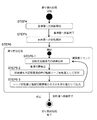
図3に被検出板19aの配置間隔情報を保存するための処理のフローを示す。この処理では、初めにかご11を基準階(通常は最下階)に移動させる(STEP1)。その後、目的階(通常は最上階)までのかご11の移動を開始する(STEP2)。この移動中、回転検出器8からの信号を積算し、被検出板19aを通過する毎に階間の距離情報として積算値を保存して、積算値をリセットする処理を行う(STEP3)。最後に、目的階までの移動が完了すると処理を終了する。
FIG. 3 shows a flow of processing for storing the arrangement interval information of the
この処理フローは、エレベータ装置の据付直後に行うことが好ましい。即ち、エレベータ装置の据付直後には、トラクション状態が健全であり、滑りが生じないため、駆動シーブ4の回転量(駆動シーブ4の外周の回転による進み量)を懸架体10の送り量とみなすことができ、回転検出器8からの信号の階間積算値を階間の距離として取り扱うことができる。
This processing flow is preferably performed immediately after installation of the elevator apparatus. That is, immediately after the elevator apparatus is installed, the traction state is healthy and no slip occurs, so the rotation amount of the drive sheave 4 (advance amount due to rotation of the outer periphery of the drive sheave 4) is regarded as the feed amount of the
また、次に説明する滑り状態判定装置22により異常な滑りがない状態であることを判断した場合は、保存情報を更新する処理を実施してもよい。
Further, when it is determined by the slip
次に、滑り検出処理について、図4で詳しく説明する。この処理でも図3と同様に、初めにかご11を基準階(通常は最下階)に移動させる(STEP4)。その後、目的階(通常は最上階)までのかご11の移動を開始する(STEP5)。この移動中、回転検出器8からの信号を積算し、被検出板19aを通過する毎に階間通過時の駆動シーブ4の回転量として積算値を保存し、積算値をリセットする処理を行う(STEP6−1,2)。
Next, the slip detection process will be described in detail with reference to FIG. In this process, as in FIG. 3, the
さらに、保存した駆動シーブ4の回転量と階間距離情報との差分を滑り量として、滑り状態判定装置22に出力する(STEP6−3)。最後に、目的階までの移動が完了すると処理を終了する。 Further, the difference between the stored rotation amount of the drive sheave 4 and the inter-story distance information is output as a slip amount to the slip state determination device 22 (STEP 6-3). Finally, when the movement to the destination floor is completed, the process is terminated.
次に、滑り状態判定装置22の判定処理について説明するため、滑り判定の対象となる複数の滑り状態を図5〜7に例示する。各図とも駆動シーブ4と懸架体10との間の滑り量の時間変化を示している。
Next, in order to describe the determination process of the slip
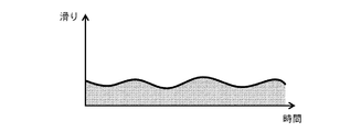
図5は正常状態で全域的に生じる小さな滑りであり、かご11の積載状態等によって多少大きさが変化するものの、局所時間で高い滑りが生じることはない。一方、図6は局所異常状態で生じる局所的で大きな滑りを示しており、これが進展すると図7で示すような継続的で大きな滑りに至る。
FIG. 5 shows a small slip that occurs in the whole area in a normal state, and although the size changes somewhat depending on the loading state of the
ここで、滑り検出装置21により検出される滑り量との関係を説明すると、図中の滑りを時間で積算した各図中の塗りつぶし部分が検出される滑り量に該当する。これらの図から明らかなように、継続的で大きな滑りが生じている場合は、滑り量が他の2例と大きく異なり、区別が容易である。しかし、正常状態で全域的で小さな滑りが生じている場合と、局所異常状態で局所的で大きな滑りが生じている場合とでは、滑り量の差異がなく(又は小さく)、滑り量のみで両者を区別することができない。
Here, the relationship with the slip amount detected by the
これに対して、図8は図5に示した全域的で小さな滑りが生じている場合の駆動シーブ4の回転速度及び巻上機モータ5の駆動力の時間変化を示すグラフ、図9は図6に示した局所的で大きな滑りが生じている場合の駆動シーブ4の回転速度及び巻上機モータ5の駆動力の時間変化を示すグラフである。 On the other hand, FIG. 8 is a graph showing the change over time of the rotational speed of the drive sheave 4 and the driving force of the hoisting machine motor 5 when the entire region shown in FIG. 6 is a graph showing temporal changes in the rotational speed of the drive sheave 4 and the driving force of the hoisting machine motor 5 when a large local slip shown in FIG. 6 occurs.
このような駆動シーブ4の回転速度及び巻上機モータ5の駆動力の変動情報を利用することで、前述した2つの状態の切り分けを行うことができる。具体的には、局所的な滑りが生じている場合、図9に示すように、駆動シーブ4の回転速度が上がると同時に巻上機モータ5の駆動力が低下する現象が生じる。 By using such fluctuation information of the rotational speed of the drive sheave 4 and the driving force of the hoisting motor 5, the above-described two states can be separated. Specifically, when local slip occurs, as shown in FIG. 9, a phenomenon occurs in which the driving speed of the hoist motor 5 decreases at the same time as the rotational speed of the drive sheave 4 increases.
これは、滑りが生じると、懸架体10と駆動シーブ4との間の摩擦力が低下することで、摩擦力が低下する直前まで加えられている駆動力により回転速度が高くなり、また、一般的なエレベータでは、指令速度に追従する制御をエレベータ制御装置31で実施するため、速度が指令値から外れないよう制御で駆動力を低減することによって生じる。
This is because, when slipping occurs, the frictional force between the
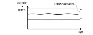
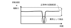
そこで、回転速度と駆動力とを掛け合わせた値に着目する。図10は図8の回転速度×駆動力の値の時間変化を示すグラフ、図11は図9の回転速度×駆動力の値の時間変化を示すグラフである。図10に示すように、全域的で小さな滑りが生じている場合、回転速度×駆動力の値は、正常時の変動範囲内でほぼ一定である。これに対して、図11に示すように、局所的で大きな滑りが生じている場合、回転速度×駆動力の値は、局所的に滑りが生じたタイミングで低下し、正常時の変動範囲から外れる。 Therefore, attention is paid to a value obtained by multiplying the rotational speed and the driving force. FIG. 10 is a graph showing the change over time of the value of the rotational speed × the driving force in FIG. 8, and FIG. 11 is a graph showing the change over time of the value of the rotational speed × the driving force in FIG. As shown in FIG. 10, when a small slip occurs over the entire area, the value of rotational speed × driving force is substantially constant within a normal fluctuation range. On the other hand, as shown in FIG. 11, when local and large slip occurs, the value of the rotational speed × driving force decreases at the timing when the slip occurs locally, and from the normal fluctuation range. Come off.
このように、回転速度と駆動力とを掛け合わせることで、局所的な滑りが生じてない通常走行の変動範囲から大きく外れる値が現れる。そして、この特徴点を捕えることで、異常をより確実に切り分けて検出することができる。即ち、回転速度と駆動力とを掛け合わせた量の正常時の変動範囲を予め定めておき、階間走行中の回転速度と駆動力との積が正常時の変動範囲を超えたことを検出することにより、局所的な滑りの発生を精度良く簡単に検出することができる。 In this way, by multiplying the rotational speed and the driving force, a value that greatly deviates from the fluctuation range of normal travel where no local slip occurs. And by capturing this feature point, it is possible to more reliably isolate and detect the abnormality. That is, a normal fluctuation range of the amount obtained by multiplying the rotation speed and the driving force is determined in advance, and it is detected that the product of the rotation speed and the driving force during traveling between the floors exceeds the normal fluctuation range. By doing so, it is possible to easily detect the occurrence of local slip with high accuracy.
なお、回転速度と駆動力とを掛け合わせる演算を実施せず、回転速度及び駆動力のそれぞれを個別に判断することで、局所的な滑りの発生を検出してもよい。 It should be noted that the occurrence of local slip may be detected by separately determining the rotational speed and the driving force without performing the calculation of multiplying the rotational speed and the driving force.
具体的には、図12に示すように、まず階間を走行するときの通常の駆動力からの許容最小偏差a1と、通常走行パターンからの回転速度の許容最大偏差b1とを定める。次に、駆動力の偏差が許容最小偏差a1を下回る事象と、回転速度の偏差が許容最大偏差b1を上回る事象とが同時に発生した場合、局所的な滑りが発生したものと判断する。 Specifically, as shown in FIG. 12, first, an allowable minimum deviation a1 from the normal driving force when traveling between floors and an allowable maximum deviation b1 of the rotational speed from the normal traveling pattern are determined. Next, when an event in which the deviation of the driving force falls below the allowable minimum deviation a1 and an event in which the deviation of the rotational speed exceeds the allowable maximum deviation b1 occur simultaneously, it is determined that local slip has occurred.
また、図13に示すように、かご11が階間を走行したときの通常の駆動力からの最小偏差a2に合わせて回転速度の変化の許容できる許容最大偏差b2を定め、回転速度の変化の最大値が許容最大偏差b2を超える場合に局所な滑りが発生したものと判断することもできる。
Further, as shown in FIG. 13, a permissible maximum deviation b2 that can change the rotational speed is determined in accordance with the minimum deviation a2 from the normal driving force when the
ここで、b2の定め方として、a2が小さくなるにつれてb2が大きくなり、またa2が大きくなるにつれてb2が小さくなるような関係を持たせるように定めると、回転量の上昇は小さいが局所的な滑りにより駆動力が低下している場合、及び駆動力の低下は小さいが局所的な滑りにより回転量が上昇している場合に、それぞれでの局所的な滑りを精度良く検出できる。 Here, as a method of determining b2, if the relationship is set such that b2 increases as a2 decreases and b2 decreases as a2 increases, the increase in the amount of rotation is small but local. When the driving force is reduced due to the slip, and when the amount of rotation is increased due to the local slip, the local slip can be accurately detected.
例えば、a2とb2とが反比例する関係を持たせると、回転速度と駆動力との積により判断するのと同等の基準で判断することができる。具体的な判断の様子として、図12では、回転速度の最大偏差は基準b2を超えているため、ここで局所的に滑りが発生していると判断できる。 For example, if a2 and b2 have an inversely proportional relationship, it can be determined based on the same standard as that determined by the product of the rotational speed and the driving force. As a specific state of determination, in FIG. 12, since the maximum deviation of the rotational speed exceeds the reference b2, it can be determined that a slip has occurred locally.
さらに、この例とは逆に、先に速度の最大偏差を特定して、これに基づいて駆動力の許容最小偏差を定め、速度がこれら許容値を超えるか否かに基づいて、局所的な滑りが発生していることの判断を行ってもよい。 Further, contrary to this example, the maximum deviation of the speed is specified first, the allowable minimum deviation of the driving force is determined based on this, and the local deviation is determined based on whether the speed exceeds these allowable values. It may be determined that slipping has occurred.
次に、滑り状態判定装置22による具体的な滑り状態判定処理のフローを図14に示す。ここでは、目的階への移動開始を受けて滑り状態判定処理に移行する。滑り状態判定処理では、滑り検出装置21からの滑り量の情報を受信し、受信した滑り量と予め定められている滑り量の第1の基準量とを比較する(STEP7−1,7−2)。
Next, FIG. 14 shows a flow of specific slip state determination processing by the slip
滑り量が第1の基準量よりも大きい場合は、第1の異常状態を出力して処理待ち状態に戻る(STEP7−3)。一方、滑り量が第1の基準量よりも小さい場合は、受信した滑り量と予め定められている滑り量の第2の基準量(第1の基準量>第2の基準量)との比較処理に移行する(STEP7−4)。 If the slip amount is larger than the first reference amount, the first abnormal state is output and the process wait state is returned (STEP 7-3). On the other hand, when the slip amount is smaller than the first reference amount, the received slip amount is compared with a second reference amount of the predetermined slip amount (first reference amount> second reference amount). The process proceeds (STEP 7-4).
滑り量が第2の基準量よりも大きい場合、さらに滑り挙動に異常がないかの評価を実施する(STEP7−5)。具体的な評価方法は、上述した通りである。 When the slip amount is larger than the second reference amount, an evaluation is further performed as to whether there is any abnormality in the slip behavior (STEP 7-5). The specific evaluation method is as described above.
滑り挙動に異常があると判定された場合は、第2の異常状態を出力して処理待ち状態に戻る(STEP7−6)。一方、STEP7−4で滑り量が基準量よりも小さい場合、及び、STEP7−5で滑り挙動に異常がないと判断された場合は、そのまま処理待ち状態に移行する。 If it is determined that there is an abnormality in the sliding behavior, the second abnormal state is output and the process waits back (STEP 7-6). On the other hand, if the slip amount is smaller than the reference amount in STEP 7-4, and if it is determined in STEP 7-5 that there is no abnormality in the slip behavior, the process shifts to the process waiting state.
ここで、第1の異常状態と第2の異常状態とは、判断閾値となる第1及び第2の基準量の設定次第で意義が変わってくる。例えば、第1の基準量は、サービス時に安全に各階停止ができないトラクション状態で生じる滑り量とする。そして、滑り量が第1の基準量よりも大きい場合は、エレベータ制御装置31がかご11を最寄り階に停止させたり、サービスを即時停止したりすることで安全性を確保する。
Here, the significance of the first abnormal state and the second abnormal state varies depending on the setting of the first and second reference amounts serving as determination thresholds. For example, the first reference amount is a slip amount generated in a traction state where each floor cannot be safely stopped during service. When the slip amount is larger than the first reference amount, safety is ensured by the
また、第2の基準量は、正常な状態で積載重量等の変動により変化する滑り量の最大値とする。そして、滑り量が、第1の基準量以下であり、第2の基準量よりも大きい場合は、エレベータ装置の状態情報を外部に伝達する。これにより、早期の状態改善につなげるという運用が考えられる。 Further, the second reference amount is set to the maximum value of the slip amount that changes due to fluctuations in the loaded weight or the like in a normal state. When the slip amount is equal to or smaller than the first reference amount and larger than the second reference amount, the state information of the elevator apparatus is transmitted to the outside. As a result, an operation that leads to an early state improvement can be considered.
状態情報を伝達する具体的な伝達装置としては、例えば、かご11内外への音声によるアナウンス、かご11内での画像又はランプ等による表示、及び利用者の携帯電話に対する電子通信が考えられる。
As a specific transmission device for transmitting the state information, for example, an announcement by voice to the inside or outside of the
また、エレベータ制御装置と保全作業者又は保守会社との間の通信手段又は携帯電話等によって、局所滑りが増加していく経過情報を通信してもよい。この場合、エレベータ装置の運転を中止しなければならない状態に至る前に保全を行うことで、エレベータ装置を継続的に運転でき、利用者に運転中止による不便をかけることがない。 Moreover, you may communicate the progress information which a local slip increases by a communication means or a mobile telephone etc. between an elevator control apparatus and a maintenance worker or a maintenance company. In this case, by performing maintenance before reaching the state where the operation of the elevator apparatus must be stopped, the elevator apparatus can be continuously operated, and the user is not inconvenienced by the operation stop.
実施の形態2.
次に、この発明の実施の形態2について説明する。実施の形態2では、実施の形態1における滑り状態判定装置22での滑り挙動判定(図14の処理ステップ7−5)において、滑りを定量的に算出することで、より精度の高い滑り判断を実現する。
Next, a second embodiment of the present invention will be described. In the second embodiment, in the slip behavior determination (processing step 7-5 in FIG. 14) in the slip
実施の形態2の滑り状態判定装置22は、滑り検出装置21により検出された滑り量情報と、巻上機モータ5の駆動力情報と、回転検出器8からの回転情報と、駆動シーブ4及びそれに連動して駆動する機器の慣性質量の情報と、懸架体10及びそれと連動して動作する機器の慣性質量の情報と、駆動シーブ4に作用するアンバランス重量の情報とに基づいて、駆動シーブ4と懸架体10との間に生じる全域的滑りと局所的な滑りとを区別する。他の構成及び動作は、実施の形態1と同様である。
The slip
式1は、駆動シーブ4と懸架体10との間の摩擦力を介してエレベータ装置が駆動する際の運動方程式である。

式1において、Jは駆動シーブ4及びそれに連動して駆動する機器の慣性質量であり、駆動シーブ4の他に巻上機モータ5のロータ等の慣性質量が含まれる。J’は懸架体10及びそれと連動して動作する機器の慣性質量であり、懸架体10、かご11及び釣合おもり12の他、そらせ車9及びかご11から吊り下げられたケーブル類(給電ケーブル及び釣合索等)等の慣性質量が含まれる。
In
Tは巻上機モータ5の出力する駆動力である。Fは駆動シーブ4と懸架体10との間に働く摩擦力である。Lは駆動シーブ4に作用するアンバランス重量であり、かご11の停止時におけるかご11側の懸架体10の張力と釣合おもり12側の懸架体10の張力との差分力である。
T is a driving force output by the hoisting machine motor 5. F is a frictional force acting between the drive sheave 4 and the
ここで、かご11側の懸架体10の張力には、かご11の重量及びかご11内の積載重量に加えて、駆動シーブ4からかご11までの懸架体10の重量、及びかご11から吊り下げられるケーブル類の重量が影響する。同様に、釣合おもり12側の懸架体10の張力も、釣合おもり12の重量に加えて、駆動シーブ4から釣合おもり12までの懸架体10重量、及び釣合おもり12から吊り下げられるケーブル類の重量が影響する。
Here, the tension of the
Wは駆動シーブ4の回転速度、Vは懸架体10の送り速度である。また、Wの上にドットを付した記号はWの時間微分、Vの上にドットを付した記号はVの時間微分を示している。
W is the rotational speed of the drive sheave 4, and V is the feed speed of the
次に、滑り速度を駆動シーブ4の回転速度に対する割合δ(滑り率)で定義すると、式2となる。
Next, when the slip speed is defined by a ratio δ (slip ratio) with respect to the rotational speed of the drive sheave 4,
![]()
![]()
これにより、式1を数式変換すると式3に示す関係式が得られる。
Thereby, when
この式3は、慣性質量J及びJ’、駆動シーブ4の回転速度W、巻上機モータ5の駆動力T、アンバランス重量L、滑り率δの関係を微分方程式として示している。そして、実施の形態2における滑り検出装置21では、式3に基づいて滑り率を算出する。
This
この滑り率の算出においては、式中δ以外の各値を定める必要がある。各値のうち、J及びJ’は、慣性質量であるため、システム構成に応じて算出することができる。また、Wは、駆動シーブ4の回転速度であるため、回転検出器8からの信号に基づいて算出できる。さらに、Tは、巻上機モータ5が出力している駆動力であるため、巻上機モータ5の駆動電流を換算して算出できる。
In calculating the slip ratio, it is necessary to determine values other than δ in the equation. Of each value, J and J ′ are inertial masses, and therefore can be calculated according to the system configuration. Since W is the rotational speed of the drive sheave 4, it can be calculated based on the signal from the
さらにまた、アンバランス重量Lは、かご11内の積載重量により変化するため、秤装置14からの信号に基づいて算出できる。
Furthermore, since the unbalance weight L varies depending on the load weight in the
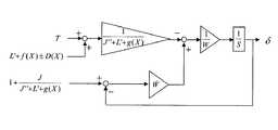
図15は式3に基づいて滑り率を導出する方法を示すブロック図である。図15では、巻上機モータ5の駆動力T、アンバランス重量L、慣性質量の関係式1+J/J’を入力として、滑り率δを算出する手順を示している。
FIG. 15 is a block diagram showing a method for deriving the slip ratio based on
図中、三角のブロックでは、入力値がブロック内の係数と乗算処理されて出力される。また、1/Sのブロックは、入力信号を積分処理して出力する積分器を示している。さらに、2つの経路の合流点では、合流するそれぞれの信号が加減算処理される。そして、入力信号を加える処理には「+」、入力信号を引く処理には「−」を、それぞれ入力信号線の横に示している。 In the figure, in the triangular block, the input value is multiplied with the coefficient in the block and output. The 1 / S block represents an integrator that integrates and outputs an input signal. Further, at the joining point of the two paths, each signal to be joined is subjected to addition / subtraction processing. “+” Is shown next to the input signal line, and “−” is shown next to the input signal line.
さらにまた、滑り率δは、出力直前で信号分岐されており、分岐された信号を前手順への入力として利用する回帰経路が設けられている。この回帰経路を通る入力は、出力値δが算出される前段階では値が定められないため利用できない。 Furthermore, the slip ratio δ is signal-branched immediately before output, and a regression path that uses the branched signal as an input to the previous procedure is provided. The input through this regression path cannot be used because the value is not determined before the output value δ is calculated.
そこで、実装時の演算では、このブロック図全体の処理を周期的に行い、回帰経路を通る入力信号として、前回以前の周期で算出した滑り率δを利用する。その際、滑り率δは時々刻々と変化するため、前回以前の周期で算出した滑り率と演算実施時の滑り率との間に誤差が生じるが、処理の周期を短くすることで出力誤差を小さくすることができる。 Therefore, in the calculation at the time of mounting, the processing of the entire block diagram is periodically performed, and the slip ratio δ calculated in the previous cycle is used as an input signal passing through the regression path. At that time, since the slip rate δ changes from moment to moment, an error occurs between the slip rate calculated in the previous cycle and the slip rate at the time of calculation, but the output error is reduced by shortening the processing cycle. Can be small.
このように、滑り状態判定装置22において、上述のエレベータ装置の運動方程式から導出した演算処理を行うことで、即ち、駆動シーブ4に作用するアンバランス重量の情報と、回転検出器8からの信号に基づいて検出した駆動シーブ4の回転量の情報と、巻上機3が発生している駆動力の情報と、駆動シーブ4及びそれに連動して駆動する機器の慣性質量の情報と、懸架体10及びそれと連動して動作する機器の慣性質量の情報とに基づいて、駆動シーブ4と懸架体10との間の滑り率δを精度良く推定することができる。
As described above, the slip
また、滑り状態判定装置22において具体的な判定に利用する滑り、即ち、駆動シーブ4の回転速度と懸架体10の送り出し速度との差は、式2から滑り率δと駆動滑車の回転速度との積により算出して得られる。このように算出した滑りの変化を監視し、これが所定の閾値を超えるかどうかを判定することにより、定量的な滑りにより正確な滑り状態の判断をすることができる。
Further, the slip used for specific determination in the slip
実施の形態3.
次に、この発明の実施の形態3について説明する。実施の形態2では、任意の一状態におけるエレベータ装置の運動方程式を基礎として滑りを推定し、滑り状態を判定する技術を示した。これに対して、実施の形態3では、さらにかご11の上下方向の位置により状態が変化することを考慮して、かご位置に応じて滑り推定処理を変更することで、滑りの推定精度を向上させる。他の構成及び動作は、実施の形態2と同様である。
Next, a third embodiment of the present invention will be described. In the second embodiment, the technique for estimating the slip state by estimating the slip based on the equation of motion of the elevator apparatus in any one state is shown. On the other hand, in the third embodiment, the slip estimation process is changed according to the car position in consideration of the fact that the state changes depending on the vertical position of the
式4は、かご位置による状態変化を考慮に入れたエレベータ装置の運動方程式を示している。 Equation 4 shows the equation of motion of the elevator apparatus taking into account the state change due to the car position.
式4では、かご11側の懸架体10の張力と釣合おもり12側の懸架体10の張力との差分力(アンバランス重量)をL’+f(X)としている。Xはかご11の位置であり、L’はかご11内の積載重量に相当する部分である。
In Expression 4, a differential force (unbalance weight) between the tension of the
また、f(X)は、駆動シーブ4に吊り下げられる懸架体10の長さ、及びかご11から吊り下げられるケーブル類(給電配線等)の長さが、かご位置で変化することによる重量変化部分で、かご位置Xに依存した値として定められる。
Further, f (X) represents a change in weight due to a change in the length of the
具体的には、例えば、負荷を与えるケーブル類の重量が位置に比例して変化する傾向を考慮するならば、かご位置に比例して変化する項をA×X、かご位置Xが0のときのかご11側の懸架体10の張力と釣合おもり12側の懸架体10の張力との差分力を補正して釣合を取るための定数項をBとして、f(X)=A×X+Bとするような一次関数で定義することができる。これにより、アンバランス重量の影響で生じる誤差を解消することができる。
Specifically, for example, when considering the tendency that the weight of cables to which a load is applied changes in proportion to the position, the term that changes in proportion to the car position is A × X, and the car position X is 0. F (X) = A × X + B where B is a constant term for correcting the differential force between the tension of the
また、かご11から吊り下げられたケーブル類は、かご位置が上昇するにつれて吊り下げ部分が長くなるため、慣性質量にも影響する。これを考慮して、運動方程式では、懸架体10と連動動作する機器の慣性質量をL’+g(X)として、かご位置Xに依存する部分をg(X)として定義している。
In addition, cables suspended from the
このg(X)についても、具体的に定めるとすれば、ケーブル類の重量が位置に比例して変化することから、例えばf(X)と同様に一次関数で定義することができる。 This g (X) can also be defined by a linear function as in the case of f (X), for example, since the weight of the cables changes in proportion to the position if specifically determined.
さらに、この運動方程式では、かご11を上下する際に作用する駆動抵抗力の影響を考慮して、その抵抗力の項を±D(X)として与えている。駆動抵抗力には、かご11とかごガイドレールとの間の摩擦力、及び釣合おもり12と釣合おもりガイドレールとの間の摩擦力が含まれており、その大きさは、かご位置によって変わるガイドレールとの接触状態に依存する。即ち、摩擦力には、局所的なガイドレールの曲がり状態、据付時のガイドレールの垂直精度の状態、ガイドレールへのごみ及び油等の付着状態が影響し、いずれの状態もガイドレールの位置によって異なるため、摩擦力の大きさはかご位置によって変化する。そのため、駆動抵抗力をD(X)として位置Xに依存する形式で与えている。
Further, in this equation of motion, the term of the resistance force is given as ± D (X) in consideration of the influence of the driving resistance force acting when the
また、駆動抵抗力は駆動方向と反対に働くため、運動方程式中では、駆動方向により正負が反転することを考慮して±D(X)としている。ここで、D(X)はレールとの接触状態により変化するため、エレベータ装置ごとの個体差によるばらつきが大きい。そのため、実際に巻上機モータ5を駆動した際に出力される駆動力Tに基づいて、かご位置による駆動抵抗力の変化D(X)を定めることで、個体差によるばらつきの影響を含んで駆動抵抗力を定めることができる。 Further, since the driving resistance acts in the opposite direction to the driving direction, in the equation of motion, ± D (X) is set in consideration of the reversal of positive and negative depending on the driving direction. Here, since D (X) varies depending on the contact state with the rail, there is a large variation due to individual differences between the elevator apparatuses. Therefore, by determining the change D (X) of the driving resistance force depending on the car position based on the driving force T output when the hoisting machine motor 5 is actually driven, the influence of variation due to individual differences is included. The driving resistance can be determined.
具体的には式4から導出した式5に基づいて、位置に応じて変化する駆動力T(X)を取得して利用することが考えられる。 Specifically, it is conceivable that the driving force T (X) that changes depending on the position is acquired and used based on Expression 5 derived from Expression 4.
![]()
![]()
特に、一定速走行では、加減速度を無視して、Vの時間微分及びWの時間微分をいずれも0として取り扱うことができるため、実質的に式6の関係が成り立つ。
In particular, when traveling at a constant speed, the acceleration / deceleration is ignored, and both the time derivative of V and the time derivative of W can be treated as 0, so the relationship of
![]()
![]()
この式では、±D(X)は走行方向により正負反転することから、上方向走行したときの駆動力及びかご位置関係Tup(X)と、下方向走行したときの駆動力及びかご位置関係Tdn(X)とがそれぞれ式7に示すように得られる。
In this equation, ± D (X) is inverted between positive and negative depending on the traveling direction. Therefore, the driving force and the car position relationship Tup (X) when traveling in the upward direction, and the driving force and the car position relationship Tdn when traveling in the downward direction. (X) is obtained as shown in
式7の両式の差により式8が得られ、式8に示す演算処理により、駆動抵抗力のかご位置に応じた関係D(X)を定めることができる。
また、式7の両式の和により得られる式9に示す演算処理を実施することで、f(X)を定めることができる。
Further, f (X) can be determined by performing the arithmetic processing shown in
f(X)は、エレベータ装置の構造により定まる特性ではあるが、実際に計測した駆動力を利用して定めることで、設計と実システムとの間にある構造誤差を解消するだけでなく、秤装置14により検出されたかご11内の積載重量L’の誤差を併せて補正することもできる。
Although f (X) is a characteristic determined by the structure of the elevator device, it is determined not only by eliminating the structural error between the design and the actual system by determining it using the actually measured driving force. The error of the loading weight L ′ in the
なお、経年による駆動シーブ4と懸架体10との間の摩擦状態の変化により、微小な滑りが起こり、V及びWの時間微分が厳密には0ではなくなる場合がある。そのため、摩擦状態が健全な状態のとき、例えばエレベータ装置を据え付けた初期に、D(X)及びf(X)を定めることが、滑り率の演算誤差を小さくする上で望ましい。
Note that a slight slip may occur due to a change in the friction state between the drive sheave 4 and the
一方、g(X)は、式5においてVの時間微分が0とはならない関係式、即ち加減速度を含む関係式として導出できる式10の演算処理を実施して定めることができる。
On the other hand, g (X) can be determined by performing the arithmetic processing of
ここでは、g(X)を定めるのに滑り率δが必要となるが、実施の形態2に示したループ経路を通る信号処理と同様に、周期的に算出処理する中で前回周期以前の処理結果として得た滑り率δを利用すればよい。 Here, the slip ratio δ is required to determine g (X), but in the same way as the signal processing through the loop path shown in the second embodiment, the processing before the previous cycle is performed periodically. The slip rate δ obtained as a result may be used.
なお、f(X)及びg(X)の例として、かご位置Xに依存する一次関数を挙げたが、それぞれのモデルは実特性に合わせて任意に選ぶことができ、多次関数又は指数関数等の近い傾向特性で近似することもでき、かご位置Xに対応する値をデータ例で保存して演算時に利用することもできる。 In addition, as an example of f (X) and g (X), a linear function depending on the car position X is given. However, each model can be arbitrarily selected according to actual characteristics, and can be a multi-order function or an exponential function. It is also possible to approximate with similar tendency characteristics such as, and it is also possible to save a value corresponding to the car position X as a data example and use it at the time of calculation.
また、かご位置Xは、滑りが生じない正常な状態で階停止位置等の基準位置から回転検出器8によりかご11の移動量を積算することで絶対位置として把握できる。
Further, the car position X can be grasped as an absolute position by accumulating the movement amount of the
以上のように定められるかご位置による状態変化を考慮した滑り率δの関係式を式11に示す。
また、式11に基づいて滑り率δを常時推定するためのブロック図を図16に示す。図16における各ブロックの定義及び演算処理は、図15の場合と同様であり、このブロックにより定義される処理により滑り率δの出力を得ることができる。
FIG. 16 shows a block diagram for constantly estimating the slip ratio δ based on the
このようなエレベータ装置では、かご位置により変動する状態を考慮した推定処理により、駆動シーブ4と懸架体10との間の滑り挙動をより精度良く把握することができ、滑り挙動による異常判断もより精度良く実施することができる。
In such an elevator apparatus, the slipping behavior between the drive sheave 4 and the
ここまでは、駆動抵抗力をD(X)としてかごの位置Xのみに依存する特性として扱ってきたが、速度Vへの依存特性も考慮してD(X,V)とすることで、推定精度をより向上させることができる。この場合、スリップ及び重量を推定する推定式において、D(X)をD(X,V)に置き換えて推定処理することで、推定精度の向上を実現できる。変動項D(X,V)は、速度Vに線形的に依存する特性であるとしてもよいし、非線形の特性として扱ってもよい。 Up to this point, the driving resistance force has been treated as a characteristic that depends only on the position X of the car as D (X), but is estimated by taking D (X, V) as a characteristic that depends on the speed V. The accuracy can be further improved. In this case, estimation accuracy can be improved by replacing D (X) with D (X, V) in the estimation formula for estimating slip and weight. The variation term D (X, V) may be a characteristic that linearly depends on the velocity V or may be treated as a non-linear characteristic.
D(X,V)を決定する処理では、定格速度が異なる運転パターンで駆動して各定格速度に対応した駆動力の情報を取得し、それぞれの駆動力情報に基づいて変動項を決定することができる。具体的には、例えば、D(X,V)が速度Vに線形依存する特性であるとして処理する場合、まず定格速度V1及びV2の2つの運転パターンで駆動して、それぞれ一定速区間の駆動力の情報を取得する。 In the process of determining D (X, V), driving with driving patterns having different rated speeds to acquire driving force information corresponding to each rated speed, and determining a variation term based on the respective driving force information Can do. Specifically, for example, when processing is performed assuming that D (X, V) is a characteristic that is linearly dependent on the speed V, first, driving is performed with two operation patterns of rated speeds V1 and V2, and driving in a constant speed section, respectively. Get force information.
これら2つの情報は、それぞれ速度は異なるものの一定値であるため、速度変化による影響を受けておらず、一方、かごの位置Xの変化による影響は受けている。そのため、まずは実施の形態2と同じ処理によって、それぞれの速度ごとにかご位置Xに依存する駆動抵抗力を定格速度V1に対してはD(X,V1)、定格速度V2に対してはD(X,V2)として定めることができる。そして、これらに基づいて、速度への線形依存を考慮したD(X,V)は以下の式により定めることができる。 These two pieces of information are constant values although their speeds are different from each other, so that they are not affected by the change in speed, but are affected by the change in the position X of the car. Therefore, first, by the same processing as in the second embodiment, the driving resistance force depending on the car position X for each speed is D (X, V1) for the rated speed V1 and D (X for the rated speed V2). X, V2). Based on these, D (X, V) considering linear dependence on speed can be determined by the following equation.
実施の形態4.
次に、この発明の実施の形態4について説明する。実施の形態4では、実施の形態2又は3の滑り状態判定装置22内において算出した滑りに誤差成分が含まれる場合に、その誤差を除去して、さらに精度良い滑り挙動判断を実現する。他の構成及び動作は、実施の形態2又は3と同様である。Embodiment 4 FIG.
Next, a fourth embodiment of the present invention will be described. In the fourth embodiment, when an error component is included in the slip calculated in the slip
図17は実施の形態4によるエレベータ装置における滑り量の補正方法を説明するためのグラフであり、実施の形態2又は3で示した手法により推定した補正前の滑り挙動と補正後の滑り挙動とを示している。また、この例は、局所異常状態により局所的で大きな滑りが生じた場合の中で、特に滑り推定に利用した積載重量情報及び検出した駆動力情報に誤差が含まれている場合における挙動例である。 FIG. 17 is a graph for explaining a method of correcting the slip amount in the elevator apparatus according to the fourth embodiment. The slip behavior before correction and the corrected slip behavior estimated by the method shown in the second or third embodiment are shown in FIG. Is shown. In addition, this example is a behavior example in the case where a local large slip occurs due to a local abnormal state, and particularly when the load weight information used for slip estimation and the detected driving force information include an error. is there.
慣性質量は通常変動することがなく、また巻上機3の回転量もエンコーダ等で検出するため誤差が生じにくい。一方、巻上機モータ5の駆動力及び秤装置14で検出する積載重量には誤差が含まれやすいため、この影響を補正することで、より精度良い滑り判断が実現できる。
The inertial mass does not normally fluctuate, and the amount of rotation of the hoisting
これらの巻上機モータ5の駆動力及び秤装置14で検出する積載重量に含まれる誤差は、推定した滑りにおいて時間に比例して増加する滑り誤差として現れる。従って、誤差の影響を除去するための具体的な処理としては、被検出板19aを通過したタイミングt1とt2とで被検出板検出器19bにより検出した滑りの傾きと一致するように、推定により得られた滑りとの傾きを補正する。これにより、推定した滑り挙動を精度良く修正できる。
The error included in the driving force of the hoist motor 5 and the load weight detected by the
具体的には、推定により得られた滑りYの傾きが時間tに依存して変化する関数を以下の式13、位置センサ19により検出した滑りY’の傾きが時間tに依存して変化する関数を、以下の式14として求める。
Specifically, a function that changes the slope of the slip Y obtained by the estimation depending on the time t is expressed by the following
Y=α1×t+β1 ・・・式13
Y = α1 × t +
Y’=α2×t+β2 ・・・式14
Y ′ = α2 × t + β2
そして、推定した補正前の各時間の滑りから、式14で算出される各時間の滑り差分値を差し引くことで、補正をすることができる。
Then, correction can be performed by subtracting the slip difference value of each time calculated by
(α1−α2)×t+(β1−β2) ・・・式15
(Α1-α2) × t + (β1-β2)
また、被検出板19a通過時の滑りを検出する1つの構成として、例えば図2に示すように、昇降路1内に設置された所定長さの被検出板19aを、かご11に設けられた被検出板検出器19bで検出する位置センサ19が用いられている。
Further, as one configuration for detecting slipping when passing through the
このような構成において、被検出板19aの通過時に被検出板19aを検出したかご位置と検出しなくなったかご位置との2点を捕えることで、1つの被検出板19aを通過した際の滑りを算出できる。具体的には、この2点を通過する間の駆動シーブ4の回転量と、被検出板19aの長さとを比較することにより、被検出板検出器19bが被検出板19aを通過するそれぞれのタイミングt1とt2とで滑りを検出することができる。
In such a configuration, slipping when passing through one detected
なお、位置センサは、被検出板19aと被検出板検出器19bとの組み合わせに限定されるものではない。
また、エレベータ装置全体のレイアウトは、図1のレイアウトに限定されるものではない。例えば、2:1ローピング方式のエレベータ装置、巻上機が昇降路の下部に設置されているエレベータ装置にもこの発明は適用できる。
さらに、この発明は、機械室レスエレベータ、ダブルデッキエレベータ、共通の昇降路内に複数のかごが配置されているワンシャフトマルチカー方式のエレベータなど、あらゆるタイプのエレベータ装置に適用できる。The position sensor is not limited to the combination of the detected
Moreover, the layout of the whole elevator apparatus is not limited to the layout of FIG. For example, the present invention can also be applied to a 2: 1 roping type elevator apparatus and an elevator apparatus in which a hoisting machine is installed at the lower part of a hoistway.
Furthermore, the present invention can be applied to all types of elevator devices such as machine room-less elevators, double deck elevators, and one-shaft multi-car elevators in which a plurality of cars are arranged in a common hoistway.
実施の形態5.
次に、この発明の実施の形態5について説明する。実施の形態5では、特に、滑り検出及び滑り状態判定をエレベータ装置から離れた遠隔地で実施する。以下、開示する以外の構成及び動作は、実施の形態1、2、3又は4と同様である。Embodiment 5. FIG.
Next, a fifth embodiment of the present invention will be described. In the fifth embodiment, in particular, slip detection and slip state determination are performed at a remote place away from the elevator apparatus. Hereinafter, configurations and operations other than those disclosed are the same as those in the first, second, third, or fourth embodiment.
図18はこの発明の実施の形態5によるエレベータ装置及びエレベータ用遠隔地状態判定装置を示す構成図である。図1に示すエレベータ装置の構成と比較すると、エレベータ装置61がエレベータ用遠隔地状態判定装置62(以下、単に遠隔地状態判定装置62と呼ぶ)と外部通信網で接続されている点が異なる。エレベータ装置自身の構成を比較すると、実施の形態5のエレベータ装置61は、滑り検出装置21及び滑り状態判定装置22を備えておらず、エレベータ情報記憶装置41及びエレベータ情報通信装置51を備えている。
FIG. 18 is a block diagram showing an elevator apparatus and an elevator remote location state determination apparatus according to Embodiment 5 of the present invention. Compared with the configuration of the elevator apparatus shown in FIG. 1, the
この構成では、実施の形態1〜4において滑り検出装置21で実施している滑り量算出処理と、滑り状態判定装置22において実施している全域的な滑りか局所的な滑りかを区別する判定処理とを、遠隔地状態判定装置62において実施する。
In this configuration, the slip amount calculation process performed by the
具体的な処理では、滑り量の演算に必要となる回転検出器8からの信号及び位置センサ19からの信号が、エレベータ情報記憶装置41に保存される。また、全域的な滑りか局所的な滑りかを区別する判定処理に必要となる巻上機モータ5の駆動力情報等も、エレベータ情報記憶装置41に保存される。エレベータ情報記憶装置41に保存された信号及び情報は、エレベータ情報通信装置51により遠隔地状態判定装置62に送信される。
In a specific process, a signal from the
また、エレベータ情報通信装置51は、遠隔地状態判定装置62で判定処理された滑り状態情報、即ち、滑りが生じているか否かという情報、滑りが生じている場合にはそれが全域的な滑りか局所的な滑りかという情報を受信する。
In addition, the elevator
エレベータ情報通信装置51で受信した情報は、エレベータ情報記憶装置41に保存される。エレベータ制御装置31は、エレベータ情報記憶装置41に保存されている滑り状態情報に基づいて、かご11を最寄り階に停止させたりサービスを即時停止したりすることで安全性を確保する。
Information received by the elevator
一方、遠隔地状態判定装置62は、状態判定処理装置23、診断情報通信装置52、及び診断情報記憶装置42を有している。状態判定処理装置23は、実施の形態1、2、3、又は4と同様の滑り検出装置21及び滑り状態判定装置22の機能を有している。
On the other hand, the remote location
診断情報通信装置52は、エレベータ情報通信装置51から送信された信号及び情報を受信する。診断情報通信装置52で受信した信号及び情報は、診断情報記憶装置42に保存される。状態判定処理装置23は、診断情報記憶装置42に保存された情報に基づいて、滑り量算出処理、全域的な滑りか局所的な滑りかを区別する判定処理を実施する。
The diagnostic
状態判定処理装置23による処理の結果は、滑り状態情報として診断情報記憶装置42に保存され、診断情報通信装置52によりエレベータ情報通信装置51へ送信される。遠隔地状態判定装置62は、上記の処理を実施することにより、多数のエレベータ装置における滑り状態を監視してエレベータ装置を一元的に安全管理することができる。
The result of the processing by the state
1 昇降路、3 巻上機、4 駆動シーブ、5 巻上機モータ、8 回転検出器、10 懸架体、11 かご、12 釣合おもり、14 秤装置、19 位置センサ、21 滑り検出装置、22 滑り状態判定装置、23 状態判定処理装置、52 診断情報通信装置、61 エレベータ装置、62 エレベータ用遠隔地状態判定装置。
DESCRIPTION OF
Claims (18)
前記駆動シーブに巻き掛けられている懸架体、
前記懸架体により昇降路内に吊り下げられており、前記巻上機モータの駆動力により昇降するかご及び釣合おもり、
前記かごが前記昇降路内の検出位置にあることを検出する位置センサ、
前記駆動シーブの回転に応じた信号を発生する回転検出器、
前記回転検出器からの信号と前記位置センサからの信号とに基づいて、前記駆動シーブと前記懸架体との間の滑り量を検出する滑り検出装置、並びに
前記滑り検出装置により検出された滑り量情報と、前記巻上機モータの駆動力情報と、前記回転検出器からの回転情報とに基づいて、前記駆動シーブと前記懸架体との間に生じる全域的滑りと局所的な滑りとを区別する滑り状態判定装置
を備え、
前記滑り状態判定装置は、前記駆動力情報の値と前記回転情報に基づく回転速度の値との積が予め定められた変動範囲を超えたことを検出した場合に、局所的な滑りが発生したものと判断するエレベータ装置。 A hoisting machine having a driving sheave and a hoisting machine motor that rotates the driving sheave;
A suspension wound around the drive sheave,
The car is suspended in a hoistway by the suspension body, and is raised and lowered by the driving force of the hoist motor, and a counterweight,
A position sensor for detecting that the car is at a detection position in the hoistway;
A rotation detector for generating a signal corresponding to the rotation of the drive sheave;
A slip detection device that detects a slip amount between the drive sheave and the suspension based on a signal from the rotation detector and a signal from the position sensor, and a slip amount detected by the slip detection device Based on the information, the driving force information of the hoisting machine motor, and the rotation information from the rotation detector, a distinction is made between the total slip and the local slip that occur between the drive sheave and the suspension. Equipped with a sliding state judging device
When the slip state determination device detects that the product of the value of the driving force information and the value of the rotation speed based on the rotation information exceeds a predetermined fluctuation range, local slip occurs. Elevator device that judges things.
前記駆動シーブに巻き掛けられている懸架体、
前記懸架体により昇降路内に吊り下げられており、前記巻上機モータの駆動力により昇降するかご及び釣合おもり、
前記かごが前記昇降路内の検出位置にあることを検出する位置センサ、
前記駆動シーブの回転に応じた信号を発生する回転検出器、
前記回転検出器からの信号と前記位置センサからの信号とに基づいて、前記駆動シーブと前記懸架体との間の滑り量を検出する滑り検出装置、並びに
前記滑り検出装置により検出された滑り量情報と、前記巻上機モータの駆動力情報と、前記回転検出器からの回転情報とに基づいて、前記駆動シーブと前記懸架体との間に生じる全域的滑りと局所的な滑りとを区別する滑り状態判定装置
を備え、
前記滑り状態判定装置は、前記駆動力情報の値が予め定められた許容最小偏差を下回る事象と、前記回転情報に基づく回転速度の値が予め定められた許容最大偏差を上回る事象とが同時発生したことを検出した場合に、局所的な滑りが発生したものと判断するエレベータ装置。 A hoisting machine having a driving sheave and a hoisting machine motor that rotates the driving sheave;
A suspension wound around the drive sheave,
The car is suspended in a hoistway by the suspension body, and is raised and lowered by the driving force of the hoist motor, and a counterweight,
A position sensor for detecting that the car is at a detection position in the hoistway;
A rotation detector for generating a signal corresponding to the rotation of the drive sheave;
A slip detection device that detects a slip amount between the drive sheave and the suspension based on a signal from the rotation detector and a signal from the position sensor, and a slip amount detected by the slip detection device Based on the information, the driving force information of the hoisting machine motor, and the rotation information from the rotation detector, a distinction is made between the total slip and the local slip that occur between the drive sheave and the suspension. Equipped with a sliding state judging device
The slip state determination device simultaneously generates an event in which the value of the driving force information falls below a predetermined allowable minimum deviation and an event in which the value of the rotational speed based on the rotation information exceeds a predetermined allowable maximum deviation An elevator apparatus that determines that a local slip has occurred when it is detected.
前記駆動シーブに巻き掛けられている懸架体、
前記懸架体により昇降路内に吊り下げられており、前記巻上機モータの駆動力により昇降するかご及び釣合おもり、
前記かごが前記昇降路内の検出位置にあることを検出する位置センサ、
前記駆動シーブの回転に応じた信号を発生する回転検出器、
前記回転検出器からの信号と前記位置センサからの信号とに基づいて、前記駆動シーブと前記懸架体との間の滑り量を検出する滑り検出装置、並びに
前記滑り検出装置により検出された滑り量情報と、前記巻上機モータの駆動力情報と、前記回転検出器からの回転情報とに基づいて、前記駆動シーブと前記懸架体との間に生じる全域的滑りと局所的な滑りとを区別する滑り状態判定装置
を備え、
前記滑り状態判定装置は、前記駆動力情報の最小値に基づいて回転速度の変化の許容できる許容最大値を定め、前記回転情報に基づく回転速度の値が前記許容最大値を超えたことを検出した場合に、局所的な滑りが発生したものと判断するエレベータ装置。 A hoisting machine having a driving sheave and a hoisting machine motor that rotates the driving sheave;
A suspension wound around the drive sheave,
The car is suspended in a hoistway by the suspension body, and is raised and lowered by the driving force of the hoist motor, and a counterweight,
A position sensor for detecting that the car is at a detection position in the hoistway;
A rotation detector for generating a signal corresponding to the rotation of the drive sheave;
A slip detection device that detects a slip amount between the drive sheave and the suspension based on a signal from the rotation detector and a signal from the position sensor, and a slip amount detected by the slip detection device Based on the information, the driving force information of the hoisting machine motor, and the rotation information from the rotation detector, a distinction is made between the total slip and the local slip that occur between the drive sheave and the suspension. Equipped with a sliding state judging device
The slip state determination device determines an allowable maximum value of change in rotational speed based on the minimum value of the driving force information, and detects that the rotational speed value based on the rotational information exceeds the allowable maximum value. If it is, an elevator apparatus that determines that local slip has occurred.
前記駆動シーブに巻き掛けられている懸架体、
前記懸架体により昇降路内に吊り下げられており、前記巻上機モータの駆動力により昇降するかご及び釣合おもり、
前記かごが前記昇降路内の検出位置にあることを検出する位置センサ、
前記駆動シーブの回転に応じた信号を発生する回転検出器、
前記回転検出器からの信号と前記位置センサからの信号とに基づいて、前記駆動シーブと前記懸架体との間の滑り量を検出する滑り検出装置、並びに
前記滑り検出装置により検出された滑り量情報と、前記巻上機モータの駆動力情報と、前記回転検出器からの回転情報とに基づいて、前記駆動シーブと前記懸架体との間に生じる全域的滑りと局所的な滑りとを区別する滑り状態判定装置
を備え、
前記滑り状態判定装置は、前記回転情報に基づく回転速度の最大値に基づいて前記駆動力情報の値の変化の許容できる許容最小値を定め、前記駆動力情報の値が前記許容最小値を下回ったことを検出した場合に、局所的な滑りが発生したものと判断するエレベータ装置。 A hoisting machine having a driving sheave and a hoisting machine motor that rotates the driving sheave;
A suspension wound around the drive sheave,
The car is suspended in a hoistway by the suspension body, and is raised and lowered by the driving force of the hoist motor, and a counterweight,
A position sensor for detecting that the car is at a detection position in the hoistway;
A rotation detector for generating a signal corresponding to the rotation of the drive sheave;
A slip detection device that detects a slip amount between the drive sheave and the suspension based on a signal from the rotation detector and a signal from the position sensor, and a slip amount detected by the slip detection device Based on the information, the driving force information of the hoisting machine motor, and the rotation information from the rotation detector, a distinction is made between the total slip and the local slip that occur between the drive sheave and the suspension. Equipped with a sliding state judging device
The slip state determination device determines an allowable minimum value of change in the value of the driving force information based on a maximum value of the rotational speed based on the rotation information, and the value of the driving force information is less than the allowable minimum value. An elevator device that determines that a local slip has occurred when it is detected.
前記駆動シーブに巻き掛けられている懸架体、
前記懸架体により昇降路内に吊り下げられており、前記巻上機モータの駆動力により昇降するかご及び釣合おもり、
前記かごが前記昇降路内の検出位置にあることを検出する位置センサ、
前記駆動シーブの回転に応じた信号を発生する回転検出器、
前記回転検出器からの信号と前記位置センサからの信号とに基づいて、前記駆動シーブと前記懸架体との間の滑り量を検出する滑り検出装置、並びに
前記滑り検出装置により検出された滑り量情報と、前記巻上機モータの駆動力情報と、前記回転検出器からの回転情報と、前記駆動シーブ及び前記巻上機モータのロータを含む前記駆動シーブに連動して駆動する機器の慣性質量の情報と、前記懸架体及びそれと連動して動作する機器の慣性質量の情報と、前記駆動シーブに作用するアンバランス重量の情報とに基づいて、前記駆動シーブと前記懸架体との間に生じる全域的滑りと局所的な滑りとを区別する滑り状態判定装置
を備えているエレベータ装置。 A hoisting machine having a driving sheave and a hoisting machine motor that rotates the driving sheave;
A suspension wound around the drive sheave,
The car is suspended in a hoistway by the suspension body, and is raised and lowered by the driving force of the hoist motor, and a counterweight,
A position sensor for detecting that the car is at a detection position in the hoistway;
A rotation detector for generating a signal corresponding to the rotation of the drive sheave;
A slip detection device that detects a slip amount between the drive sheave and the suspension based on a signal from the rotation detector and a signal from the position sensor, and a slip amount detected by the slip detection device Information, the driving force information of the hoisting machine motor, the rotation information from the rotation detector, and the inertial mass of the device driven in conjunction with the driving sheave and the driving sheave including the rotor of the hoisting machine motor Is generated between the drive sheave and the suspension based on the information on the inertial mass of the suspension body and the device operating in conjunction therewith and the information on the unbalanced weight acting on the drive sheave. An elevator apparatus equipped with a slip condition judging device for distinguishing between total slip and local slip.
前記滑り状態判定装置は、前記秤装置からの信号に基づいて、前記駆動シーブに作用するアンバランス重量を算出する請求項5に記載のエレベータ装置。 Further comprising a scale device for generating a signal corresponding to the load weight in the car;
The elevator apparatus according to claim 5, wherein the slippage state determination device calculates an unbalanced weight that acts on the drive sheave based on a signal from the scale device.
前記滑り状態判定装置は、前記被検出板の検出範囲の通過信号と、前記駆動シーブの回転量と、前記被検出板の検出範囲とに応じて、滑り情報を用いて滑り状態判定処理を変更する請求項5又は請求項6に記載のエレベータ装置。 The position sensor has a detected plate installed in the hoistway and a detected plate detector mounted on the car and detecting the detected plate.
The slip state determination device changes the slip state determination process using slip information according to a passing signal of the detection range of the detection plate, a rotation amount of the drive sheave, and a detection range of the detection plate. The elevator apparatus according to claim 5 or 6.
前記駆動シーブに巻き掛けられている懸架体、
前記懸架体により昇降路内に吊り下げられており、前記巻上機モータの駆動力により昇降するかご及び釣合おもり、
前記かごが前記昇降路内の検出位置にあることを検出する位置センサ、並びに
前記駆動シーブの回転に応じた信号を発生する回転検出器
を備えているエレベータ装置の制御方法であって、
前記回転検出器からの信号と前記位置センサからの信号とに基づいて、前記駆動シーブと前記懸架体との間の滑り量を検出するステップ、
前記巻上機モータの駆動力情報の値と前記回転検出器からの回転情報の回転速度の値との積及び検出された前記滑り量情報に基づいて、前記駆動シーブと前記懸架体との間に生じる全域的滑りと局所的な滑りとを区別するステップ
を含むエレベータ装置の制御方法。 A hoisting machine having a driving sheave and a hoisting machine motor that rotates the driving sheave;
A suspension wound around the drive sheave,
The car is suspended in a hoistway by the suspension body, and is raised and lowered by the driving force of the hoist motor, and a counterweight,
A control method of an elevator apparatus comprising: a position sensor that detects that the car is at a detection position in the hoistway; and a rotation detector that generates a signal corresponding to the rotation of the drive sheave,
Detecting a slip amount between the drive sheave and the suspension based on a signal from the rotation detector and a signal from the position sensor;
Based on the product and detected the slip information of the value of the rotational speed of the rotation information from the value before Symbol rotation detector of the driving force information before Kimaki upper motor, and the drive sheave and the suspension member A method for controlling an elevator apparatus, comprising the step of distinguishing between total slip and local slip that occur during
をさらに含む請求項14に記載のエレベータ装置の制御方法。 When the slip amount between the drive sheave and the suspension exceeds a reference amount, the car is moved to the nearest floor to stop, the elevator device is stopped immediately, or the status information of the elevator device is sent to the outside of the elevator device. The method for controlling an elevator apparatus according to claim 14, further comprising a step of transmitting.
をさらにを含む請求項14に記載のエレベータ装置の制御方法。 When the local slip between the drive sheave and the suspension exceeds a reference amount, the car is moved to the nearest floor to stop, the elevator device is immediately stopped, or status information of the elevator device is sent to the elevator device. The method for controlling an elevator apparatus according to claim 14, further comprising a step of transmitting to the outside.
前記駆動シーブに巻き掛けられている懸架体、
前記懸架体により昇降路内に吊り下げられており、前記巻上機モータの駆動力により昇降するかご及び釣合おもり、
前記かごが前記昇降路内の検出位置にあることを検出する位置センサ、並びに
前記駆動シーブの回転に応じた信号を発生する回転検出器
を備えているエレベータ装置の状態を判定する遠隔地状態判定装置であって、
前記回転検出器からの信号と前記位置センサからの信号とに基づいて、前記駆動シーブと前記懸架体との間の滑り量を検出するとともに、前記巻上機モータの駆動力情報の値と前記回転検出器からの回転情報の回転速度の値との積及び検出した前記滑り量情報に基づいて、前記駆動シーブと前記懸架体との間に生じる全域的滑りと局所的な滑りとを区別する状態判定処理装置、及び
前記回転検出器からの信号、前記位置センサからの信号、及び前記巻上機モータの駆動力情報を前記エレベータ装置から受信するとともに、前記状態判定処理装置による処理の結果である滑り状態情報を前記エレベータ装置に送信する診断情報通信装置
を備えているエレベータ用遠隔地状態判定装置。 A hoisting machine having a driving sheave and a hoisting machine motor that rotates the driving sheave;
A suspension wound around the drive sheave,
The car is suspended in a hoistway by the suspension body, and is raised and lowered by the driving force of the hoist motor, and a counterweight,
Remote location state determination that determines the state of an elevator apparatus that includes a position sensor that detects that the car is at a detection position in the hoistway and a rotation detector that generates a signal corresponding to the rotation of the drive sheave A device,
Based on the signal from the signal and the position sensor from said rotation detector, and the value of the driving force information detects the slip amount, before Kimaki upper motor between the suspension member and the drive sheave based on the slippage information product and detection of the value of the rotational speed of the rotation information from the previous SL rotation detector, and a whole manner sliding and local slippage occurring between the suspension member and the drive sheave The state determination processing device to be distinguished, the signal from the rotation detector, the signal from the position sensor, and the driving force information of the hoisting machine motor are received from the elevator device, and the processing by the state determination processing device A remote state determination device for an elevator, comprising: a diagnostic information communication device that transmits slip state information as a result to the elevator device.
前記駆動シーブに巻き掛けられている懸架体、
前記懸架体により昇降路内に吊り下げられており、前記巻上機モータの駆動力により昇降するかご及び釣合おもり、
前記かごが昇降路内の検出位置にあることを検出する位置センサ、
前記駆動シーブの回転に応じた信号を発生する回転検出器、
前記回転検出器からの信号、前記位置センサからの信号、前記巻上機モータの駆動力情報、及び、滑り状態情報を保存するエレベータ情報記憶装置、並びに
前記エレベータ情報記憶装置に保存されている前記回転検出器からの信号、前記位置センサからの信号、前記巻上機モータの駆動力情報を送信し、前記滑り状態情報を受信するエレベータ情報通信装置を備え、
前記エレベータ情報通信装置は、前記回転検出器からの信号と前記位置センサからの信号とに基づいて、前記駆動シーブと前記懸架体との間の滑り量を検出するとともに、前記巻上機モータの駆動力情報の値と前記回転検出器からの回転情報の回転速度の値との積及び検出した前記滑り量情報に基づいて、前記駆動シーブと前記懸架体との間に生じる全域的滑りと局所的な滑りとを区別した結果を前記滑り状態情報として受信するエレベータ装置。 A hoisting machine having a driving sheave and a hoisting machine motor that rotates the driving sheave;
A suspension wound around the drive sheave,
The car is suspended in a hoistway by the suspension body, and is raised and lowered by the driving force of the hoist motor, and a counterweight,
A position sensor for detecting that the car is at a detection position in the hoistway;
A rotation detector for generating a signal corresponding to the rotation of the drive sheave;
An elevator information storage device that stores a signal from the rotation detector, a signal from the position sensor, driving force information of the hoist motor, and slip state information, and the elevator information storage device that stores the elevator information storage device An elevator information communication device for transmitting a signal from a rotation detector, a signal from the position sensor, driving force information of the hoisting motor, and receiving the slip state information;
The elevator information communication apparatus, based on a signal from the signal and the position sensor from said rotation detector detects a slippage between the suspension member and the drive sheave, before Kimaki upper motor based on the slippage information product and detection of the value of the rotational speed of the rotation information from the value before Symbol rotation detector of the driving force information, the entire basis slippage occurring between the suspension member and the drive sheave The elevator apparatus which receives the result which discriminate | determined from local slip as said slip condition information.
Applications Claiming Priority (3)
| Application Number | Priority Date | Filing Date | Title |
|---|---|---|---|
| JP2015108616 | 2015-05-28 | ||
| JP2015108616 | 2015-05-28 | ||
| PCT/JP2016/065201 WO2016190281A1 (en) | 2015-05-28 | 2016-05-23 | Elevator device, control method therefor, and remote determination device for elevator state |
Publications (2)
| Publication Number | Publication Date |
|---|---|
| JPWO2016190281A1 JPWO2016190281A1 (en) | 2017-06-15 |
| JP6152965B2 true JP6152965B2 (en) | 2017-06-28 |
Family
ID=57392774
Family Applications (1)
| Application Number | Title | Priority Date | Filing Date |
|---|---|---|---|
| JP2016559371A Active JP6152965B2 (en) | 2015-05-28 | 2016-05-23 | ELEVATOR DEVICE, ITS CONTROL METHOD, AND ELEVATOR REMOTE STATE STATE DETERMINATION DEVICE |
Country Status (4)
| Country | Link |
|---|---|
| JP (1) | JP6152965B2 (en) |
| CN (1) | CN107614409B (en) |
| DE (1) | DE112016002403T5 (en) |
| WO (1) | WO2016190281A1 (en) |
Families Citing this family (6)
| Publication number | Priority date | Publication date | Assignee | Title |
|---|---|---|---|---|
| WO2017203561A1 (en) * | 2016-05-23 | 2017-11-30 | 三菱電機株式会社 | Elevator apparatus |
| EP3760559A1 (en) * | 2019-07-05 | 2021-01-06 | KONE Corporation | Measurement arrangement and method of monitoring rotation speed of a component of an elevator, escalator, moving walkway or moving ramp |
| WO2021005658A1 (en) * | 2019-07-05 | 2021-01-14 | 三菱電機株式会社 | Elevator control system |
| JP7161819B2 (en) * | 2019-12-18 | 2022-10-27 | 三菱電機株式会社 | elevator equipment |
| CN111453582A (en) * | 2020-04-23 | 2020-07-28 | 巨人通力电梯有限公司 | Time limiting method based on absolute position well signal system |
| CN115285819A (en) * | 2022-08-16 | 2022-11-04 | 巨立电梯股份有限公司 | Protection system of elevator safety device and elevator |
Family Cites Families (10)
| Publication number | Priority date | Publication date | Assignee | Title |
|---|---|---|---|---|
| JPH01178008A (en) * | 1987-12-29 | 1989-07-14 | Hiroo Hojo | Spike tire |
| JPH0733228B2 (en) * | 1989-08-07 | 1995-04-12 | 三菱電機株式会社 | Elevator abnormality detection device |
| JPH10226470A (en) * | 1997-02-17 | 1998-08-25 | Toshiba Elevator Kk | Elevator vibration analyzer |
| JP2000118903A (en) * | 1998-10-12 | 2000-04-25 | Hitachi Ltd | Elevator |
| JP2001341956A (en) * | 2000-06-05 | 2001-12-11 | Toshiba Corp | Remote maintenance method and remote maintenance system for elevator |
| EP1749780B1 (en) * | 2004-05-28 | 2012-03-07 | Mitsubishi Denki Kabushiki Kaisha | Elevator rope slip detector and elevator system |
| CN101537955A (en) * | 2009-04-30 | 2009-09-23 | 北京市朝阳区特种设备检测所 | Elevator non-load traction capacity detecting method |
| JP2014043291A (en) * | 2012-08-24 | 2014-03-13 | Hitachi Ltd | Elevator system and elevator control device |
| JP6271956B2 (en) * | 2013-11-12 | 2018-01-31 | 株式会社日立製作所 | elevator |
| JP6216238B2 (en) * | 2013-12-06 | 2017-10-18 | 株式会社日立製作所 | Elevator |
-
2016
- 2016-05-23 CN CN201680028194.3A patent/CN107614409B/en active Active
- 2016-05-23 WO PCT/JP2016/065201 patent/WO2016190281A1/en active Application Filing
- 2016-05-23 JP JP2016559371A patent/JP6152965B2/en active Active
- 2016-05-23 DE DE112016002403.7T patent/DE112016002403T5/en active Pending
Also Published As
| Publication number | Publication date |
|---|---|
| JPWO2016190281A1 (en) | 2017-06-15 |
| DE112016002403T5 (en) | 2018-03-01 |
| CN107614409B (en) | 2019-06-21 |
| CN107614409A (en) | 2018-01-19 |
| WO2016190281A1 (en) | 2016-12-01 |
Similar Documents
| Publication | Publication Date | Title |
|---|---|---|
| JP6152965B2 (en) | ELEVATOR DEVICE, ITS CONTROL METHOD, AND ELEVATOR REMOTE STATE STATE DETERMINATION DEVICE | |
| JP5675898B2 (en) | Elevator equipment | |
| CN1741949B (en) | Elevator system | |
| EP2186768B1 (en) | Elevator device | |
| JP6058160B2 (en) | Elevator apparatus and control method thereof | |
| JPWO2011101978A1 (en) | Elevator equipment | |
| JP2011042480A (en) | Elevator device | |
| EP2743225B1 (en) | Elevator system | |
| JP6569807B2 (en) | Elevator equipment | |
| JP5079351B2 (en) | Elevator equipment | |
| US10486935B2 (en) | Elevator diagnosing device | |
| JP2010089869A (en) | Rope slipping detection device of elevator and elevator device using the same | |
| JPWO2020031284A1 (en) | Elevator diagnostic system | |
| EP3650384B1 (en) | System for monitoring lobby activity to determine whether to cancel elevator service | |
| JP7155342B1 (en) | Elevator control device and elevator control method | |
| CN101844718B (en) | Elevator device | |
| JPWO2019215844A1 (en) | Test methods for elevators and emergency stop devices | |
| CN109956381B (en) | Safety elevator system | |
| EP4313829A1 (en) | Method and system for estimating rope slip in an elevator system | |
| JP2021116148A (en) | Wear inspection system of rope-type elevator and wear inspection method |
Legal Events
| Date | Code | Title | Description |
|---|---|---|---|
| A131 | Notification of reasons for refusal |
Free format text: JAPANESE INTERMEDIATE CODE: A131 Effective date: 20170228 |
|
| A521 | Request for written amendment filed |
Free format text: JAPANESE INTERMEDIATE CODE: A523 Effective date: 20170405 |
|
| TRDD | Decision of grant or rejection written | ||
| A01 | Written decision to grant a patent or to grant a registration (utility model) |
Free format text: JAPANESE INTERMEDIATE CODE: A01 Effective date: 20170418 |
|
| A61 | First payment of annual fees (during grant procedure) |
Free format text: JAPANESE INTERMEDIATE CODE: A61 Effective date: 20170516 |
|
| R150 | Certificate of patent or registration of utility model |
Ref document number: 6152965 Country of ref document: JP Free format text: JAPANESE INTERMEDIATE CODE: R150 |
|
| R250 | Receipt of annual fees |
Free format text: JAPANESE INTERMEDIATE CODE: R250 |
|
| R250 | Receipt of annual fees |
Free format text: JAPANESE INTERMEDIATE CODE: R250 |
|
| R250 | Receipt of annual fees |
Free format text: JAPANESE INTERMEDIATE CODE: R250 |
|
| R250 | Receipt of annual fees |
Free format text: JAPANESE INTERMEDIATE CODE: R250 |