JP6152770B2 - Management program, management method, and information processing apparatus - Google Patents
Management program, management method, and information processing apparatus Download PDFInfo
- Publication number
- JP6152770B2 JP6152770B2 JP2013209889A JP2013209889A JP6152770B2 JP 6152770 B2 JP6152770 B2 JP 6152770B2 JP 2013209889 A JP2013209889 A JP 2013209889A JP 2013209889 A JP2013209889 A JP 2013209889A JP 6152770 B2 JP6152770 B2 JP 6152770B2
- Authority
- JP
- Japan
- Prior art keywords
- information
- setting
- setting information
- change
- rule
- Prior art date
- Legal status (The legal status is an assumption and is not a legal conclusion. Google has not performed a legal analysis and makes no representation as to the accuracy of the status listed.)
- Expired - Fee Related
Links
- 238000007726 management method Methods 0.000 title claims description 66
- 230000010365 information processing Effects 0.000 title claims description 14
- 238000004364 calculation method Methods 0.000 claims description 50
- 238000000034 method Methods 0.000 claims description 41
- 238000012545 processing Methods 0.000 claims description 15
- 238000010586 diagram Methods 0.000 description 20
- 230000006870 function Effects 0.000 description 14
- 238000004891 communication Methods 0.000 description 10
- 230000003287 optical effect Effects 0.000 description 6
- 230000007704 transition Effects 0.000 description 6
- 230000001186 cumulative effect Effects 0.000 description 4
- 238000000605 extraction Methods 0.000 description 4
- 230000007423 decrease Effects 0.000 description 3
- 230000002093 peripheral effect Effects 0.000 description 3
- 230000004397 blinking Effects 0.000 description 2
- 239000003086 colorant Substances 0.000 description 2
- 230000000694 effects Effects 0.000 description 2
- 238000005516 engineering process Methods 0.000 description 2
- 238000011084 recovery Methods 0.000 description 2
- 239000004065 semiconductor Substances 0.000 description 2
- 238000012790 confirmation Methods 0.000 description 1
- 238000003745 diagnosis Methods 0.000 description 1
- 239000000284 extract Substances 0.000 description 1
- 238000009434 installation Methods 0.000 description 1
- 230000001788 irregular Effects 0.000 description 1
- 239000004973 liquid crystal related substance Substances 0.000 description 1
- 238000012544 monitoring process Methods 0.000 description 1
- 230000003449 preventive effect Effects 0.000 description 1
- 238000012360 testing method Methods 0.000 description 1
Images


Classifications
-
- H—ELECTRICITY
- H04—ELECTRIC COMMUNICATION TECHNIQUE
- H04L—TRANSMISSION OF DIGITAL INFORMATION, e.g. TELEGRAPHIC COMMUNICATION
- H04L67/00—Network arrangements or protocols for supporting network services or applications
- H04L67/01—Protocols
- H04L67/10—Protocols in which an application is distributed across nodes in the network
- H04L67/1097—Protocols in which an application is distributed across nodes in the network for distributed storage of data in networks, e.g. transport arrangements for network file system [NFS], storage area networks [SAN] or network attached storage [NAS]
-
- H—ELECTRICITY
- H04—ELECTRIC COMMUNICATION TECHNIQUE
- H04L—TRANSMISSION OF DIGITAL INFORMATION, e.g. TELEGRAPHIC COMMUNICATION
- H04L67/00—Network arrangements or protocols for supporting network services or applications
- H04L67/34—Network arrangements or protocols for supporting network services or applications involving the movement of software or configuration parameters
-
- H—ELECTRICITY
- H04—ELECTRIC COMMUNICATION TECHNIQUE
- H04L—TRANSMISSION OF DIGITAL INFORMATION, e.g. TELEGRAPHIC COMMUNICATION
- H04L41/00—Arrangements for maintenance, administration or management of data switching networks, e.g. of packet switching networks
- H04L41/08—Configuration management of networks or network elements
- H04L41/0803—Configuration setting
- H04L41/0813—Configuration setting characterised by the conditions triggering a change of settings
- H04L41/0816—Configuration setting characterised by the conditions triggering a change of settings the condition being an adaptation, e.g. in response to network events
-
- H—ELECTRICITY
- H04—ELECTRIC COMMUNICATION TECHNIQUE
- H04L—TRANSMISSION OF DIGITAL INFORMATION, e.g. TELEGRAPHIC COMMUNICATION
- H04L41/00—Arrangements for maintenance, administration or management of data switching networks, e.g. of packet switching networks
- H04L41/08—Configuration management of networks or network elements
- H04L41/085—Retrieval of network configuration; Tracking network configuration history
- H04L41/0853—Retrieval of network configuration; Tracking network configuration history by actively collecting configuration information or by backing up configuration information
-
- H—ELECTRICITY
- H04—ELECTRIC COMMUNICATION TECHNIQUE
- H04L—TRANSMISSION OF DIGITAL INFORMATION, e.g. TELEGRAPHIC COMMUNICATION
- H04L41/00—Arrangements for maintenance, administration or management of data switching networks, e.g. of packet switching networks
- H04L41/08—Configuration management of networks or network elements
- H04L41/0893—Assignment of logical groups to network elements
-
- H—ELECTRICITY
- H04—ELECTRIC COMMUNICATION TECHNIQUE
- H04L—TRANSMISSION OF DIGITAL INFORMATION, e.g. TELEGRAPHIC COMMUNICATION
- H04L41/00—Arrangements for maintenance, administration or management of data switching networks, e.g. of packet switching networks
- H04L41/14—Network analysis or design
- H04L41/147—Network analysis or design for predicting network behaviour
Description
本発明は、複数の装置を有するシステムを管理する管理プログラム、管理方法、および情報処理装置に関する。 The present invention relates to a management program, a management method, and an information processing apparatus for managing a system having a plurality of apparatuses.
コンピュータシステムは、ネットワークを介して様々なサービスをユーザに提供することができる。このようにネットワークを介してサービスを提供する場合、そのサービスを安定して提供できることが重要である。 The computer system can provide various services to a user via a network. Thus, when providing a service via a network, it is important that the service can be provided stably.
正常に動作していたシステムが正常に動作しなくなる要因の1つに、システム内のコンピュータに設定するパラメータなどの設定変更がある。例えばクラウドコンピューティングによりサービスを提供する場合、大規模なICT(Information and Communication Technology)システムを運用する。大規模なシステム内の各コンピュータの設定を変更すると、その設定変更によりシステムに障害が発生する可能性がある。ところが、システム内に多数のコンピュータが含まれる場合、設定変更によりどの程度の障害発生リスクがあるのかを把握するのは、容易ではない。 One of the factors that cause a system that has been operating normally to stop operating normally is a setting change such as a parameter set in a computer in the system. For example, when a service is provided by cloud computing, a large-scale ICT (Information and Communication Technology) system is operated. If the settings of each computer in a large-scale system are changed, the change in the settings may cause a failure in the system. However, when a large number of computers are included in the system, it is not easy to grasp the degree of failure occurrence risk due to setting changes.
そこで、多様な計算機の集合について、管理者が指定した計算機集合に属する計算機のみに対して設定パラメータを一括して変更できるようにすると共に、運用規則に現状の計算機の設定が合っているかを容易に診断できるようにする技術が考えられている。この技術では、各管理対象計算機の設定値として、上位階層の設定値が継承して使用されているかどうかの判定により、ネットワークシステムの運用規準を満たしているかどうかが判断される。 Therefore, for various computer sets, it is possible to change the setting parameters for only the computers belonging to the computer set specified by the administrator at the same time, and it is easy to check whether the current computer settings match the operating rules. A technology that enables diagnosis is considered. In this technique, it is determined whether or not the network system operation standard is satisfied by determining whether or not the setting value of the upper hierarchy is inherited and used as the setting value of each managed computer.
パラメータなどの情報の設定変更を行う場合、設定変更によるシステムへの影響が分かれば、設定変更の実施前に、影響に合わせた予防策をとることができる。例えば設定変更によるシステムへの影響が少なく障害発生の危険性も低いのであれば、設定変更後の動作確認を短時間で済ませることができる。他方、設定変更がシステムに大きな影響を及ぼし、障害発生の危険性が高い場合、ユーザの少ない時間帯に設定変更を行うか、あるいは設定変更後の運用監視を通常より厳密に長期間行うといった対策を採ることができる。 When changing the setting of information such as parameters, if the impact on the system due to the setting change is known, it is possible to take preventive measures according to the impact before the setting change is performed. For example, if the setting change does not affect the system and the risk of failure is low, the operation check after the setting change can be completed in a short time. On the other hand, if the setting change has a major impact on the system and the risk of failure is high, measures should be taken to change the setting during a time when there are few users, or to perform operation monitoring after the setting change for a longer time than usual. Can be taken.
しかし、上位階層の設定値が継承して使用されているかどうかだけでは、その設定によるシステムへの影響がどの程度なのかを認識することはできない。そのため、システムへの影響に応じた適切な障害対策を採ることができない。 However, it is not possible to recognize how much the setting has an influence on the system only by whether the setting value of the upper hierarchy is inherited and used. For this reason, it is not possible to take an appropriate countermeasure for failure according to the influence on the system.
1つの側面では、本件は、設定変更によるシステムへの影響を判定できるようにすることを目的とする。 In one aspect, the purpose of the present case is to be able to determine the influence of the setting change on the system.
1つの案では、複数の集合に分類された複数の装置を有するシステムを管理する管理プログラムが提供される。この管理プログラムは、コンピュータに、特定の集合に属する装置のうちの第1の割合の装置の設定情報の変更予定を示す変更予定情報に基づいて、同一集合に属する装置のうちの少なくとも一部の装置の設定情報を変更したときの内容を含む履歴情報を記憶する記憶手段から、同一集合に属する装置のうちの、第1の割合と所定の類似関係を満たす第2の割合の装置の設定情報を変更したときの履歴情報を取得し、取得した履歴情報に基づいて、変更予定情報に示される設定情報の変更を行うことによるシステムへの影響を予測する、処理を実行させる。 In one proposal, a management program for managing a system having a plurality of devices classified into a plurality of sets is provided. The management program causes the computer to change at least some of the devices belonging to the same set based on the change schedule information indicating the change schedule of the setting information of the first proportion of the devices belonging to the specific set. From the storage means for storing history information including the contents when the setting information of the device is changed, the setting information of the second proportion of the devices that belong to the same set and satisfy a predetermined similarity relationship among the devices belonging to the same set The history information at the time of changing is acquired, and based on the acquired history information, the process of predicting the influence on the system by changing the setting information indicated in the change schedule information is executed.
1態様によれば、設定変更によるシステムへの影響を判定することができる。 According to the first aspect, it is possible to determine the influence on the system due to the setting change.
以下、本実施の形態について図面を参照して説明する。なお各実施の形態は、矛盾のない範囲で複数の実施の形態を組み合わせて実施することができる。
〔第1の実施の形態〕
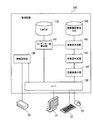
図1は、第1の実施の形態に係る情報処理装置の機能構成例を示す図である。情報処理装置10は、記憶手段11、決定手段12、取得手段13、および予測手段14を有している。
Hereinafter, the present embodiment will be described with reference to the drawings. Each embodiment can be implemented by combining a plurality of embodiments within a consistent range.
[First Embodiment]
FIG. 1 is a diagram illustrating a functional configuration example of the information processing apparatus according to the first embodiment. The
記憶手段11は、複数の履歴情報を記憶する。履歴情報は、同一集合に属する装置のうちの少なくとも一部の装置の設定情報を変更したときの内容を含む。設定情報を変更したときの内容には、設定情報を変更したことのシステムへの影響度合いを含めることができる。例えば履歴情報には、設定情報種別、変更割合、および重要度が含まれる。設定情報種別は、装置において値が変更された設定情報の種別(例えば設定項目名)である。変更割合は、値が変更された設定情報について、共通の値を設定するようにルールによって指定された集合に属する装置のうち、同時に設定変更が行われた装置が占める割合である。重要度は、設定変更がシステムに与える影響の度合いを示す数値である。
The
決定手段12は、特定の集合に属する装置のうちの第1の割合の装置の設定情報の変更予定を示す変更予定情報1において、第1の割合の計算の基礎となる情報が示されているとき、その情報を用いて第1の割合を計算する。例えば変更予定情報1には、設定変更対象の少なくとも1つの装置、値を変更する設定情報の種別、および変更後の設定値が指定されている。なお第1の割合は、例えば値を変更予定の設定情報について、共通の値を設定するようにルールによって指定された集合に属する装置のうち、同時に設定変更が行われる装置が占める割合を示している。
In the
また決定手段12では、システム内の複数の装置が、階層構造の集合に分類して管理されている。図1の例では、4階層の集合に分類したときの階層間の関係をツリー構造で表している。ツリー構造における下位の階層の集合は、その上位階層の集合の部分集合である。第1の階層には、すべての装置を含む集合2が1つだけ設けられている。第2の階層には、第1階層の集合2の部分集合である複数の集合3a,3b,・・・が設けられている。第3階層には、第2階層の集合3a,3b,・・・の部分集合である複数の集合4a,4b,・・・が設けられている。最下位の階層である第4階層には、第3階層の集合4a,4b,・・・の部分集合として、装置ごとの集合が設けられている。
In addition, the
さらに決定手段12には、設定情報の種別ごとに、設定情報の値をどの階層の集合で共通化するのかに関するルールが定義されている。例えばある種別の設定情報に関し、第1階層で共通化するというルールであれば、第1階層の集合2に属する装置の該当種別の設定情報には、共通の値を設定することになる。またある種別の設定情報に関し、第2階層で共通化するというルールであれば、第2階層の集合3a,3b,・・・ごとに、その集合に属する装置の該当種別の設定情報には、共通の値を設定することになる。このルールは、標準設定をするためのルールであって、強制ではない。そのため、ルールを逸脱した設定も可能である。
Further, the determination means 12 defines a rule relating to which set of levels the setting information value is shared for each type of setting information. For example, if it is a rule that a certain type of setting information is shared in the first hierarchy, a common value is set in the setting information of the corresponding type of the devices belonging to the
決定手段12は、変更予定情報1が入力されると、値を変更する設定情報の種別に適用されるルールに示される階層の集合のうち、変更予定情報1に示される、設定対象の少なくとも1つの装置が共に属する集合を特定する。そして決定手段12は、特定した集合に属する装置に対する、設定対象の装置の割合を、第1の割合と決定する。決定手段12は、決定した第1の割合を、取得手段13に通知する。
When the
なお取得手段13は、変更予定情報1において、第1の割合が直接的に示されている場合も考えられる。この場合、情報処理装置10に入力された変更予定情報1は、決定手段12を介さずに取得手段13に入力される。
Note that the
取得手段13は、変更予定情報1に基づいて、記憶手段11から、同一集合に属する装置のうちの、第1の割合と所定の類似関係を満たす第2の割合の装置の設定情報を変更したときの履歴情報を取得する。例えば取得手段13は、第2の割合が、第1の割合を中心とする所定の範囲内にあれば、所定の類似関係を満たすと判断する。
Based on the
また取得手段13は、第1の割合や第2の割合に所定の計算を施した上で、類似関係を判断することもできる。例えば取得手段13は、第1の割合または第2の割合の逆数をイレギュラー度と定義する。第1の割合に関するイレギュラー度は、設定変更を実施した場合の、集合内の各装置の設定値の、ルールからの乖離度合いを示す指標である。第2の割合に関するイレギュラー度は、履歴情報が記録された原因となる設定変更が実施された後の、集合内の各装置の設定値の、ルールからの乖離度合いを示す指標である。例えば取得手段13は、第1の割合に関するイレギュラー度と、第2の割合に関するイレギュラー度との差(または比)が、所定の範囲内であれば、所定の類似関係にあると判断する。
The
さらに取得手段13は、設定変更直前における、集合に属する装置の設定情報の値の統一度合いを、イレギュラー度に反映させてもよい。例えば取得手段13は、変更対象となる装置と同じ集合に属する装置それぞれの設定情報のうち、値を変更する設定情報と同じ種別の設定情報(ルール上共通の値を設定することになっている設定情報)の値を比較する。そして取得手段13は、ルールからの乖離度合いを計算し、計算結果を、所定の類似関係を満たすかどうかの判定に利用する。ルールからの乖離度合いは、例えばエントロピで表される。例えば取得手段13は、第1の割合または第2の割合の逆数を、「エントロピ+1」で除算した値をイレギュラー度とする。
Furthermore, the
取得手段13は、記憶手段11から取得した履歴情報を、予測手段14に送信する。
予測手段14は、取得した履歴情報に基づいて、変更予定情報1に示される設定情報の変更を行うことによるシステムへの影響度合いを予測する。例えば予測手段14は、取得した履歴情報に示されている重要度に基づいて、影響度合いを予測することができる。重要度を用いる場合、例えば予測手段14は、取得した履歴情報に示されている重要度の平均を影響度合いとする。また予測手段14は、第1の割合と第2の割合との類似度が高い履歴情報ほど、その履歴情報の内容を、予測に強く反映させてもよい。さらに予測手段14は、取得した履歴情報に示される重要度の分布から、予測した重要度の偏差値を計算し、その偏差値を所定の閾値と比較することで、予定されている設定変更の危険度のランクを判定することもできる。
The
The prediction means 14 predicts the degree of influence on the system by changing the setting information indicated in the
このような情報処理装置10によれば、変更予定情報1が入力されると、決定手段12により変更割合が計算される。図1の例では、変更予定情報1において、装置「machine#1」における種別「parameter#1」の設定情報の値を変更することが示されている。ここで、種別「parameter#1」には、ルール「第2階層共通」が適用されることが定義されている。また装置「machine#1」は、第2階層の集合3a,3b,・・・のうち、集合3aに属している。集合3aに属する装置は、100台あるものとする。変更予定情報1において設定変更の対象となる装置数は1台であるため、変更割合は「1/100」となる。この変更割合が、第1の割合に決定される。
According to such an
決定された第1の割合は、取得手段13に通知される。すると取得手段13において、第1の割合「1/100」と所定の類似関係の変更割合を有する履歴情報が、記憶手段11から抽出される。例えば割合を逆数にしたとき、第1の割合の逆数に対する上下10%以下の範囲の収まるような変更割合について、所定の類似関係があると判断される。この場合、「1/90」〜「1/110」の範囲の変更割合であれば、類似関係があると判断される。変更割合の類似関係が認められた履歴情報は、記憶手段11から抽出され、予測手段14に転送される。
The determined first ratio is notified to the
そして予測手段14によって、変更予定情報1に示される設定情報の変更を実施した場合のシステムへの影響度合いが計算される。例えば抽出された履歴情報の重要度が「9」と「7」であれば、平均値「8」を影響度合いとすることができる。
Then, the degree of influence on the system when the setting information indicated in the
このようにして、設定変更を行おうとしているユーザは、影響の度合いを定量的に認識できる。影響の度合いが分かれば、影響の度合いに応じて、設定変更を実施する前に障害対策を施したり、設定変更後の動作確認の期間を変えたりすることができる。その結果、設定変更を行うことに伴うシステムの信頼性の低下を抑止することができる。 Thus, the user who is going to change the setting can quantitatively recognize the degree of influence. If the degree of influence is known, it is possible to take countermeasures against troubles before changing the setting or change the operation confirmation period after changing the setting according to the degree of influence. As a result, it is possible to suppress a decrease in system reliability associated with the setting change.
ところで、同じ種別の設定情報を変更したことによる障害事例があれば、その障害事例の履歴情報を参考にして影響の度合いを判断できる。しかし、同じ種別の設定情報を変更したことによる障害事例がないと、そのような、類似する障害事例の判断が困難となる。 By the way, if there is a failure case caused by changing the setting information of the same type, the degree of influence can be determined with reference to the history information of the failure case. However, if there is no failure case caused by changing the setting information of the same type, it is difficult to determine such a similar failure case.
第1の実施の形態では、集合内での設定変更の対象となる装置の割合に基づいて、履歴情報を抽出するため、例えば、値を変更する設定情報と同じ種別の設定情報の変更に関する履歴情報が存在していなくても、影響の度合いを判断できる。集合内での設定変更の対象となる装置の割合に基づいて履歴情報を抽出することで、影響の度合いの判断に有効である理由は、以下の通りである。 In the first embodiment, since history information is extracted based on the ratio of devices that are targets of setting changes in the set, for example, history related to changes in setting information of the same type as the setting information whose value is changed Even if there is no information, the degree of influence can be determined. The reason why the history information is extracted based on the ratio of the devices whose settings are to be changed in the set is effective in determining the degree of influence is as follows.
例えば特定の種別の設定情報に対する設定変更前に、ルールに従って、特定の集合内の装置に共通の値が設定されている場合、一部の装置における設定情報の値を変更すれば、ルールから乖離した状態となる。過去に、ルールからの同程度の乖離状態を発生させた設定変更事例があれば、その事例に関する履歴情報が、今回の設定変更についての影響度合いの参考となる。設定変更後のルールからの乖離状態は、集合内での設定変更の対象となる装置の割合により推定できる。従って、集合内での設定変更の対象となる装置の割合と所定の類似関係にある履歴情報を抽出すれば、予定している設定変更を実施した場合の影響度合いを求めるのに有用な履歴情報を抽出できる。 For example, if a common value is set for a device in a specific set according to a rule before changing the setting for a specific type of setting information, changing the value of the setting information for some devices will deviate from the rule. It will be in the state. In the past, if there is a setting change case that has caused the same degree of divergence from the rule, the history information related to that case can be used as a reference for the degree of influence of this setting change. The divergence state from the rule after the setting change can be estimated by the ratio of the devices that are the target of the setting change in the set. Therefore, if history information that has a predetermined similarity with the ratio of devices that are subject to setting changes in the set is extracted, history information that is useful for determining the degree of influence when a planned setting change is performed. Can be extracted.
なお、決定手段12、取得手段13、および予測手段14は、例えば情報処理装置10が有するプロセッサにより実現することができる。また、記憶手段11は、例えば情報処理装置10が有するメモリにより実現することができる。
In addition, the determination means 12, the acquisition means 13, and the prediction means 14 are realizable with the processor which the
また、図1に示した各要素間を接続する線は通信経路の一部を示すものであり、図示した通信経路以外の通信経路も設定可能である。
〔第2の実施の形態〕
次に第2の実施の形態について説明する。第2の実施の形態は、複数のデータセンタのサーバなどの機器に対する設定情報(例えばパラメータ)の値を変更する場合の障害発生の危険度を予測するものである。
Also, the lines connecting the elements shown in FIG. 1 indicate a part of the communication path, and communication paths other than the illustrated communication paths can be set.
[Second Embodiment]
Next, a second embodiment will be described. The second embodiment predicts the risk of failure when changing the value of setting information (for example, parameters) for devices such as servers in a plurality of data centers.
図2は、第2の実施の形態のシステム構成例を示す図である。複数のデータセンタ31,32,33,・・・が、ネットワーク30を介して接続されている。データセンタ31には、複数のサーバ41,42,43,・・・や複数のストレージ装置51,52,・・・が設置されている。複数のサーバ41,42,43,・・・および複数のストレージ装置51,52,・・・は、スイッチ20を介して接続されている。他のデータセンタ32,33,・・・にも、複数のサーバや複数のストレージ装置が設けられている。
FIG. 2 is a diagram illustrating a system configuration example according to the second embodiment. A plurality of
データセンタ31には、さらに管理装置100が設けられている。管理装置100は、システム全体の運用を管理する。例えば管理装置100は、スイッチ20を介して、各データセンタ31,32,33,・・・内の機器にアクセスし、各機器の環境設定を行う。管理装置100は、環境設定において設定情報の値を変更する場合、その設定情報の値の変更による障害発生の危険度を見積もることができる。システムの管理者は、管理装置100で見積もられた危険度に応じて、設定情報の値の設定変更の際の手順を変えることができる。例えば管理者は、危険度が高い場合、システムの運用に支障が出ないように、十分なバックアップ体制を取った上で、設定情報の値の設定変更を実行する。また管理者は、危険度が低い場合、システムの運用を継続しながら、効率的な手順で設定情報の値の設定変更を実行する。
The
このような危険度の予測が可能な管理装置100は、図3に示すようなハードウェアのコンピュータで実現できる。
図3は、管理装置のハードウェアの一構成例を示す図である。管理装置100は、プロセッサ101によって装置全体が制御されている。プロセッサ101には、バス109を介してメモリ102と複数の周辺機器が接続されている。プロセッサ101は、マルチプロセッサであってもよい。プロセッサ101は、例えばCPU(Central Processing Unit)、MPU(Micro Processing Unit)、またはDSP(Digital Signal Processor)である。プロセッサ101の機能の少なくとも一部を、ASIC(Application Specific Integrated Circuit)、PLD(Programmable Logic Device)などの電子回路で実現してもよい。
The
FIG. 3 is a diagram illustrating a configuration example of hardware of the management apparatus. The
メモリ102は、管理装置100の主記憶装置として使用される。メモリ102には、プロセッサ101に実行させるOS(Operating System)のプログラムやアプリケーションプログラムの少なくとも一部が一時的に格納される。また、メモリ102には、プロセッサ101による処理に必要な各種データが格納される。メモリ102としては、例えばRAM(Random Access Memory)などの揮発性の半導体記憶装置が使用される。
The
バス109に接続されている周辺機器としては、HDD(Hard Disk Drive)103、グラフィック処理装置104、入力インタフェース105、光学ドライブ装置106、機器接続インタフェース107およびネットワークインタフェース108がある。
Peripheral devices connected to the bus 109 include an HDD (Hard Disk Drive) 103, a
HDD103は、内蔵したディスクに対して、磁気的にデータの書き込みおよび読み出しを行う。HDD103は、管理装置100の補助記憶装置として使用される。HDD103には、OSのプログラム、アプリケーションプログラム、および各種データが格納される。なお、補助記憶装置としては、フラッシュメモリなどの不揮発性の半導体記憶装置を使用することもできる。
The
グラフィック処理装置104には、モニタ21が接続されている。グラフィック処理装置104は、プロセッサ101からの命令に従って、画像をモニタ21の画面に表示させる。モニタ21としては、CRT(Cathode Ray Tube)を用いた表示装置や液晶表示装置などがある。
A
入力インタフェース105には、キーボード22とマウス23とが接続されている。入力インタフェース105は、キーボード22やマウス23から送られてくる信号をプロセッサ101に送信する。なお、マウス23は、ポインティングデバイスの一例であり、他のポインティングデバイスを使用することもできる。他のポインティングデバイスとしては、タッチパネル、タブレット、タッチパッド、トラックボールなどがある。
A
光学ドライブ装置106は、レーザ光などを利用して、光ディスク24に記録されたデータの読み取りを行う。光ディスク24は、光の反射によって読み取り可能なようにデータが記録された可搬型の記録媒体である。光ディスク24には、DVD(Digital Versatile Disc)、DVD−RAM、CD−ROM(Compact Disc Read Only Memory)、CD−R(Recordable)/RW(ReWritable)などがある。
The
機器接続インタフェース107は、管理装置100に周辺機器を接続するための通信インタフェースである。例えば機器接続インタフェース107には、メモリ装置25やメモリリーダライタ26を接続することができる。メモリ装置25は、機器接続インタフェース107との通信機能を搭載した記録媒体である。メモリリーダライタ26は、メモリカード27へのデータの書き込み、またはメモリカード27からのデータの読み出しを行う装置である。メモリカード27は、カード型の記録媒体である。
The
ネットワークインタフェース108は、スイッチ20に接続されている。ネットワークインタフェース108は、スイッチ20を介して、他のコンピュータまたは通信機器との間でデータの送受信を行う。
The
以上のようなハードウェア構成によって、第2の実施の形態の処理機能を実現することができる。なお、第1の実施の形態に示した情報処理装置10も、図3に示した管理装置100と同様のハードウェアにより実現することができる。なお図2に示した各サーバも、管理装置100と同様のハードウェアで実現することができる。
With the hardware configuration described above, the processing functions of the second embodiment can be realized. The
管理装置100は、例えばコンピュータ読み取り可能な記録媒体に記録されたプログラムを実行することにより、第2の実施の形態の処理機能を実現する。管理装置100に実行させる処理内容を記述したプログラムは、様々な記録媒体に記録しておくことができる。例えば、管理装置100に実行させるプログラムをHDD103に格納しておくことができる。プロセッサ101は、HDD103内のプログラムの少なくとも一部をメモリ102にロードし、プログラムを実行する。また管理装置100に実行させるプログラムを、光ディスク24、メモリ装置25、メモリカード27などの可搬型記録媒体に記録しておくこともできる。可搬型記録媒体に格納されたプログラムは、例えばプロセッサ101からの制御により、HDD103にインストールされた後、実行可能となる。またプロセッサ101が、可搬型記録媒体から直接プログラムを読み出して実行することもできる。
The
管理装置100は、プロセッサ101の制御により、サーバなどの機器の設定情報などの設定変更機能や、設定変更に伴う危険度の予測機能を実現する。
図4は、管理装置の機能を示すブロック図である。管理装置100は、情報の管理機能として、例えばHDD103内に、構成管理データベース(CMDB:Configuration Management Database)110と障害履歴管理データベース(DB)とが、予め構築されている。
The
FIG. 4 is a block diagram illustrating functions of the management apparatus. In the
CMDB110は、システムの構成を示す情報を管理するデータベースである。例えばCMDB110には、システム内の機器の接続関係が階層化され、ツリー構造で管理されている。またCMDB110には、システム内の機器に環境設定の設定情報(例えばパラメータ)に値を設定する際の、標準的な設定規則を示すルールが登録されている。このルールは、標準的な設定を行うためのルールであり、このルールから逸脱した設定も許容される。ただし、ルールから逸脱した設定を行った場合、その設定により、システムに障害が発生する危険性がある。
The
障害履歴管理DB120は、システムにおいて過去に発生した障害の履歴を管理するデータベースである。例えば障害履歴管理DB120には、サーバなどの機器に対する環境設定の変更が原因で発生した障害に関する履歴(障害履歴)が格納される。障害履歴には、その障害の重要度が含まれる。重要度は、例えばシステムに重大な影響を及ぼす障害であれば大きな値が設定され、システムに対する影響が軽微な障害であれば小さな値が設定される。また設定情報の値を変更したことによる障害に関する障害履歴であれば、その障害履歴には、例えば設定情報の値の変更時のイレギュラー度が含まれる。イレギュラー度は、適用されるルールからの乖離度(ルールから逸脱した設定値がどの程度あるか)を示す指標である。
The failure
管理装置100は、情報処理機能として、ユーザインタフェース(U/I)130、イレギュラー度算出部141、重要度予測部142、危険度判定部143、危険度表示部144、および情報設定部150を有する。
The
U/I130は、ユーザとの間で情報のやりとりをするインタフェースである。U/I130は、例えばキーボード22やマウス23などの入力デバイスからの入力を受け付け、他の要素に入力内容を通知する。機器の環境設定を変更する場合、管理者であるユーザが、キーボード22などを用いて、変更内容を示す変更予定情報を入力する。するとU/I130は、入力された変更予定情報を、イレギュラー度算出部141に変更予定情報を送信する。またU/I130は、適用する設定変更内容を示す変更情報が入力されると、変更情報を情報設定部150に送信する。さらにU/I130は、他の要素から処理結果を受け取ると、処理結果をモニタ21に表示する。例えばU/I130は、危険度表示部144から設定変更に伴う危険度が通知されると、その危険度をモニタ21に表示する。
The U /
イレギュラー度算出部141は、変更予定情報を受け取ると、CMDB110を参照し、イレギュラー度を算出する。イレギュラー度は、設定変更予定による変更後の設定の、標準設定ルールからの乖離度合いを示す数値である。イレギュラー度算出部141は、イレギュラー度算出結果を、重要度予測部142に送信する。
When the
重要度予測部142は、障害履歴に基づいて、予定している設定変更によって障害が生じた場合の、その障害の重要度を予測する。例えば重要度予測部142は、入力された変更予定情報に関連する障害履歴(関連障害履歴)を、障害履歴管理DB120から検索する。そして重要度予測部142は、関連障害履歴に設定されている重要度に基づいて、変更予定情報に示される設定変更によって障害が発生した場合の重要度を予測する。関連障害履歴には、例えば設定変更情報に基づいて算出されたイレギュラー度と類似するイレギュラー度の障害履歴が含まれる。また変更予定の設定情報と同種の設定情報の値を変更したときの障害履歴を、関連障害履歴に含めてもよい。重要度予測部142は、例えば、障害履歴管理DB120から関連障害履歴を抽出し、関連障害履歴に設定されている重要度の平均を、重要度の予測値(予測重要度)とする。重要度予測部142は、算出した予測重要度を危険度判定部143に通知する。
The importance
危険度判定部143は、予測重要度に基づいて、変更予定情報で示される変更内容を適用することで発生する障害の危険度を判定する。例えば危険度判定部143は、関連障害履歴に示される障害の重要度が高いほど、危険度が高くなるような計算式で、危険度を算出する。危険度判定部143は、算出した危険度を、危険度表示部144に通知する。例えば危険度判定部143は、危険度を示す数値を、多段階にランク分けする。そして危険度判定部143は、危険度のランクを危険度表示部144に通知する。
The risk
危険度表示部144は、U/I130に対して、通知された危険度をモニタ21に表示させる。例えば危険度表示部144は、危険度のランクを示す画面の表示要求を、U/I130に送信する。
The danger
情報設定部150は、U/I130を介して、サーバなどの機器への情報設定の指示を受け取ると、スイッチ20を介して、設定対象の機器にアクセスし、パラメータなどの設定情報を設定する。
Upon receiving an information setting instruction to a device such as a server via the U /
なお、図4に示した各要素間を接続する線は通信経路の一部を示すものであり、図示した通信経路以外の通信経路も設定可能である。また図4に示すイレギュラー度算出部141は、第1の実施の形態における決定手段12の一例である。また図4に示す重要度予測部142は、第1の実施の形態における取得手段13と予測手段14とを組み合わせた機能の一例である。また図4に示す危険度判定部143は、第1の実施の形態における予測手段14の一部の機能の一例である。
Note that the lines connecting the elements shown in FIG. 4 indicate a part of the communication paths, and communication paths other than the illustrated communication paths can be set. Moreover, the
次に、管理装置100に予め格納される情報について、詳細に説明する。
図5は、CMDBに格納される情報の一例を示す図である。CMDB110には、ツリー情報111とルール管理表112とが格納されている。ツリー情報111は、システム内のサーバ間の接続関係を、階層構造で示す情報である。ルール管理表112は、設定情報に適用される、設定共通化のルールを示す情報である。
Next, information stored in advance in the
FIG. 5 is a diagram illustrating an example of information stored in the CMDB. In the
図6は、ツリー情報のデータ構造の一例を示す図である。ツリー情報111は、各サーバが属するグループを、木構造(ツリー61)で階層的に表したものである。例えば第1階層には、「全体」のグループが1つだけ属している。第2階層には、データセンタ(DC)ごとの複数のグループが属している。第3階層には、データセンタ内に設定されたサーバのラックごとの、複数のグループが属している。最下位の第4階層には、サーバが属している。なお第2の実施の形態におけるグループは、第1の実施の形態の集合の一例である。
FIG. 6 is a diagram illustrating an example of a data structure of tree information. The
各グループには、ツリー61において、そのグループ以下の構造に属するサーバが属する。例えば「全体」のグループには、システム内のすべてのサーバが属する。データセンタのグループには、対応するデータセンタ内のサーバが属する。ラックのグループには、対応するラックに収納されたサーバが属する。サーバのグループは、1台のサーバ1つのグループとなる。このような、ツリーで表される階層構造が、ツリー情報111で定義されている。
Each group includes servers belonging to the structure below the group in the tree 61. For example, all servers in the system belong to the “whole” group. A server in the corresponding data center belongs to the data center group. A server stored in a corresponding rack belongs to a group of racks. The server group is a group of one server. Such a hierarchical structure represented by a tree is defined by the
ツリー情報111は、ツリー61の構造を示す情報である。図6の例ではツリー情報111には、階層、グループ、下位のグループの欄が設けられている。階層の欄には、ツリー61における階層が設定されている。グループの欄には、対応する階層に属するグループ(機器の集合)のグループ名が設定されている。下位のグループの欄には、各グループに属する下位のグループのグループ名が設定されている。例えば「全体」のグループの下位には、データセンタごとのグループが属している。データセンタのグループの下位には、ラックごとのグループが属している。ラックのグループの下位には、個々のサーバが属している。
The
第2の実施の形態では、システム内の全サーバ数が1000台であるものとする。そして10箇所のデータセンタに、サーバが100台ずつ設置されているものとする。またデータセンタ内には、10台のサーバが組み込まれたラックが、10台設置されているものとする。 In the second embodiment, it is assumed that the total number of servers in the system is 1000. Assume that 100 servers are installed in 10 data centers. It is assumed that 10 racks in which 10 servers are incorporated are installed in the data center.
次に、ルール管理表112のデータ構造について説明する。
図7は、ルール管理表のデータ構造の一例を示す図である。ルール管理表112には、ID、サーバ、設定ファイル名、設定項目名、設定値、ルール、およびルール対象サーバ数の欄が設けられている。
Next, the data structure of the rule management table 112 will be described.
FIG. 7 is a diagram illustrating an example of a data structure of the rule management table. The rule management table 112 has columns for ID, server, setting file name, setting item name, setting value, rule, and number of rule target servers.
IDの欄には、ルールの識別番号が設定される。サーバの欄には、ルールを適用するサーバの名称が設定される。設定ファイル名の欄には、情報を設定するファイルの場所と名前が設定される。設定項目名の欄には、ファイル内の設定情報の名称(設定項目名)が設定される。設定値の欄には、サーバの設定情報として、現在設定されている値が設定される。 A rule identification number is set in the ID column. The name of the server to which the rule is applied is set in the server column. In the setting file name column, the location and name of the file for setting information are set. In the setting item name column, the name of the setting information in the file (setting item name) is set. In the setting value column, a currently set value is set as server setting information.
ルールの欄には、設定情報に設定する値に関する、標準設定のルールが設定される。ルールでは、例えばどのグループの範囲で共通の値を設定するのかが定義される。例えばルールが「第1階層共通」の場合、システム内のすべてのサーバにおいて、同じ値を設定するのが標準である。またルールが「第2階層共通」の場合、同じデータセンタに属するすべてのサーバにおいて、同じ値を設定するのが標準である。またルールが「サーバ個別」の場合、サーバごとに個別の値を設定するのが標準である。 In the rule column, a standard setting rule related to a value set in the setting information is set. The rule defines, for example, in which group range a common value is set. For example, when the rule is “common to the first hierarchy”, it is standard to set the same value in all servers in the system. When the rule is “common to the second hierarchy”, it is standard to set the same value in all servers belonging to the same data center. When the rule is “individual server”, it is standard to set an individual value for each server.
ルール対象サーバ数の欄には、ルールに厳密に従った場合に同じ値が設定されるサーバの数が設定される。例えばルールが「第1階層共通」であれば、システム内の全サーバ数が、ルール対象サーバ数(1000台)となる。ルールが「第2階層共通」であれば、サーバの欄に示されるサーバが属するデータセンタ内のサーバ数(100台)が、ルール対象サーバ数となる。またルールが「サーバ個別」であれば、ルール対象サーバ数は「1」である。 The number of servers to which the same value is set when strictly following the rules is set in the rule target server number column. For example, if the rule is “common to the first layer”, the total number of servers in the system is the number of rule target servers (1000). If the rule is “common to second layer”, the number of servers in the data center (100 units) to which the server indicated in the server column belongs becomes the number of rule target servers. If the rule is “individual server”, the number of rule target servers is “1”.
次に、図8〜図11を参照して、ルールの適用例について説明する。
図8は、ルール「第1階層共通」の適用例を示す図である。ルールが「第1階層共通」の場合、ルールに厳密に従うと、第1階層のグループ「全体」に属するサーバ(システムのすべてのサーバ)に共通の値が設定される。
Next, a rule application example will be described with reference to FIGS.
FIG. 8 is a diagram illustrating an application example of the rule “common to the first layer”. In the case where the rule is “common to the first layer”, a value common to the servers (all servers in the system) belonging to the group “whole” of the first layer is set if the rule is strictly followed.
図9は、ルール「第2階層共通」の適用例を示す図である。ルールが「第2階層共通」の場合、ルールに厳密に従うと、同じデータセンタに属するサーバには共通の値が設定される。 FIG. 9 is a diagram illustrating an application example of the rule “common to second layer”. When the rule is “common to the second hierarchy”, a common value is set for servers belonging to the same data center if the rule is strictly followed.
図10は、ルール「第3階層共通」の適用例を示す図である。ルールが「第3階層共通」の場合、ルールに厳密に従うと、同じラックに搭載されたサーバには共通の値が設定される。 FIG. 10 is a diagram illustrating an application example of the rule “common to the third hierarchy”. When the rule is “common to the third level”, a common value is set for servers mounted in the same rack if the rule is strictly followed.
図11は、ルール「サーバ個別」の適用例を示す図である。ルールが「サーバ個別」の場合、各サーバに任意の値が設定される。
次に、障害履歴管理DB120について詳細に説明する。
FIG. 11 is a diagram illustrating an application example of the rule “individual server”. When the rule is “individual server”, an arbitrary value is set for each server.
Next, the failure
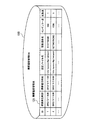
図12は、障害履歴管理DBのデータ構造の一例を示す図である。障害履歴管理DB120には、障害履歴管理表121が格納されている。障害履歴管理表121には、ID、障害発生時刻、障害復旧時刻、設定ファイル名、設定項目名、イレギュラー度、および重要度の欄が設けられている。
FIG. 12 is a diagram illustrating an example of a data structure of the failure history management DB. A failure history management table 121 is stored in the failure
IDの欄には、障害履歴の識別番号が設定される。障害発生時刻の欄には、障害が発生した日時が設定される。障害復旧時刻の欄には、障害が復旧した日時が設定される。設定ファイル名の欄には、障害発生後の原因となった情報設定が行われたファイルの場所とファイル名が設定される。設定項目名の欄には、障害発生の原因となった情報設定が行われた設定情報の名称が設定される。イレギュラー度の欄には、障害発生の原因となった情報設定のイレギュラー度が設定される。障害履歴のイレギュラー度の算出方法は、イレギュラー度算出部141によるイレギュラー度の算出方法と同じである。重要度の欄には、障害の重要度が設定される。例えば重要度の高い障害ほど、重要度として高い値が設定される。
In the ID column, an identification number of the failure history is set. The date and time when the failure occurred is set in the column of the failure occurrence time. In the column for failure recovery time, the date and time when the failure was recovered is set. In the setting file name column, the location and file name of the file in which the information setting causing the failure has been set are set. In the setting item name column, the name of the setting information in which the information setting that caused the failure has been set is set. In the irregularity column, the irregularity of the information setting that caused the failure is set. The method for calculating the irregularity of the failure history is the same as the method for calculating the irregularity by the
なお図12の例では、設定変更が障害の原因となった障害履歴を例示しているが、障害履歴管理表121には、他の原因による障害履歴が含まれる場合もある。設定変更以外の原因で発生した障害に関する障害履歴の場合、例えば設定ファイル名や設定項目名の欄は、空欄となる。また設定変更以外の原因で発生した障害に関する障害履歴の原因を詳細に登録するために、障害履歴管理表に、原因を登録する欄を追加してもよい。 In the example of FIG. 12, the failure history in which the setting change causes the failure is illustrated, but the failure history management table 121 may include failure histories due to other causes. In the case of a failure history related to a failure caused by a cause other than the setting change, for example, the setting file name and setting item name columns are blank. In addition, in order to register in detail the cause of a failure history related to a failure caused by a cause other than a setting change, a column for registering the cause may be added to the failure history management table.
以上のような内容のDBを用いて、U/I130、イレギュラー度算出部141、重要度予測部142、危険度判定部143、および危険度表示部144の連携動作により、設定変更を行うことによる危険度が予測される。
Using the DB having the above contents, the setting is changed by the cooperative operation of the U /
図13は、危険度予測処理の手順の一例を示すフローチャートである。
[ステップS101]U/I130は、サーバに対する設定情報の変更内容の入力を受け付ける。例えばU/I130は、変更予定情報入力画面をモニタ21に表示する。そしてU/I130は、変更予定情報入力画面に設けられた入力フィールドにユーザが入力した変更内容を取得する。U/I130は、取得した変更内容を、変更予定情報としてイレギュラー度算出部141に送信する。変更予定情報には、例えば変更対象のサーバ、設定ファイル名、変更項目名、および設定値が含まれる。
FIG. 13 is a flowchart illustrating an example of the procedure of the risk degree prediction process.
[Step S <b> 101] The U /
[ステップS102]イレギュラー度算出部141は、取得した変更予定情報に基づいて、その変更が適用された場合のイレギュラー度を算出する。イレギュラー度算出部141は、イレギュラー度算出結果を重要度予測部142に送信する。なおイレギュラー度算出処理の詳細は後述する(図14〜図17参照)。
[Step S102] The
[ステップS103]重要度予測部142は、イレギュラー度算出結果に基づいて障害履歴管理DB120から関連障害履歴を検索し、検索結果に基づいて、重要度を予測する。そして重要度予測部142は、得られた予測重要度を、危険度判定部143に送信する。なお重要度予測処理の詳細は後述する(図18〜図20参照)。
[Step S103] The importance
[ステップS104]危険度判定部143は、予測重要度に基づいて、情報の設定変更を行うことによる障害発生の危険度を判定する。危険度判定部143は、危険度の判定結果を、危険度表示部144に送信する。なお危険度算出処理の詳細は後述する(図21、図22参照)。
[Step S <b> 104] The
[ステップS105]危険度表示部145は、取得した危険度の判定結果をモニタ21に表示する。その結果、管理者は、設定変更を適用することによる危険度を、定量的に認識できる。
[Step S <b> 105] The risk level display unit 145 displays the acquired risk level determination result on the
以下、図13のステップS102〜ステップS104の各処理を詳細に説明する。
<イレギュラー度算出>
第2の実施の形態で算出するイレギュラー度としては、例えば、以下のような性質を持つようにする。
Hereafter, each process of step S102-step S104 of FIG. 13 is demonstrated in detail.
<Irregularity calculation>
The irregularity calculated in the second embodiment has, for example, the following properties.
以下のような場合、イレギュラー度が低くなるようにする。
・イレギュラー度「低」:例1
「サーバ個別」ルールに所属する設定情報の値の変更を、1台のサーバに対してだけ行う場合。
・イレギュラー度「低」:例2
「第1階層共通」ルールに所属する設定情報の値の、別の共通値への変更を、すべてのサーバに対して行う場合。
In the following cases, the irregularity should be lowered.
・ Irregularity “low”: Example 1
When changing the value of the setting information belonging to the “individual server” rule only for one server.
・ Irregularity “low”: Example 2
When changing the value of the setting information belonging to the “common to the first hierarchy” rule to another common value for all servers.
また以下のような場合、イレギュラー度が高くなるようにする。
・イレギュラー度「高」:例1
「第1階層共通」ルールに所属する設定情報の値の変更を、1台のサーバに対してだけ行う場合。
In the following cases, the irregularity is increased.
・ Irregularity “High”: Example 1
When changing the value of the setting information belonging to the “common to the first hierarchy” rule only for one server.
さらに以下のような場合、イレギュラー度が中間的な値となるようにする。
・イレギュラー度「中」:例1
「第2階層共通」、「第3階層共通」など中間的なレイヤーで共通している設定情報の値の変更を、1台のサーバに対してだけ行う場合。
In the following cases, the irregularity is set to an intermediate value.
・ Irregularity “Medium”: Example 1
When changing the value of setting information common to intermediate layers such as “common to second layer” and “common to third layer” for only one server.
イレギュラー度は、例えば、以下の計算式に求められる。
イレギュラー度=ルール対象サーバ数/変更サーバ数/(1+ルール対象範囲内エントロピ) ・・・(1)
ルール対象サーバ数は、ルール管理表112から取得できる。変更サーバ数は、変更予定情報に示される、変更対象のサーバの数である。ルール対象範囲内エントロピは、同一ルールが適用されるサーバ内での設定情報のエントロピ(平均情報量)である。エントロピは、情報の出現確率の偏りの度合いを表すものである。1つの情報が出現確率「1」で出現する場合、エントロピは0となる。複数の情報が、それぞれ1未満の確率で出現する場合、エントロピは正の実数となる。また複数の情報の出現頻度の偏りが大きいほど、エントロピは小さくなる。ルール対象範囲内エントロピは、以下の式で求められる。
ルール対象範囲内エントロピ=−ΣP(A)logP(A) ・・・(2)
ここで、P(A)は、変更対象の設定情報と同じルールが適用されるサーバにおいて、その設定情報に現在設定されている値(A)の出現確率である。Σは、総和を表す記号である。対数(log)の底は、例えば「2」とする。ルールが適用されるサーバ内での、適用対象の種別の設定情報の値が完全に統一されている場合、ルール対象範囲内エントロピは「0」となる。ルールから逸脱した値が設定されたサーバが多くなるほど、ルール対象範囲内エントロピの値が大きくなる。すなわち、ルール対象範囲内エントロピは、設定変更前におけるルールからの乖離度合いを示している。
The irregularity is obtained, for example, by the following calculation formula.
Irregularity = number of rule target servers / number of changed servers / (1 + rule target entropy) (1)
The number of rule target servers can be acquired from the rule management table 112. The number of change servers is the number of servers to be changed indicated in the change schedule information. The rule target range entropy is an entropy (average amount of information) of setting information in a server to which the same rule is applied. Entropy represents the degree of bias in the appearance probability of information. When one piece of information appears with an appearance probability “1”, the entropy is zero. When multiple pieces of information appear with a probability of less than 1, each entropy is a positive real number. In addition, the greater the deviation in the appearance frequency of the plurality of information, the smaller the entropy. The entropy within the rule target range is obtained by the following formula.
Rule target range entropy = −ΣP (A) logP (A) (2)
Here, P (A) is the appearance probability of the value (A) currently set in the setting information in the server to which the same rule as the setting information to be changed is applied. Σ is a symbol representing the sum. The base of the logarithm (log) is, for example, “2”. In the server to which the rule is applied, when the value of the setting information of the type to be applied is completely unified, the entropy within the rule target range is “0”. As the number of servers set with values deviating from the rule increases, the entropy value within the rule target range increases. That is, the rule target range entropy indicates the degree of deviation from the rule before the setting is changed.
次に、イレギュラー度の算出手順について説明する。
図14は、イレギュラー度の算出手順の一例を示すフローチャートである。
[ステップS111]イレギュラー度算出部141は、変更対象の設定情報に適用されるルールを取得する。例えばイレギュラー度算出部141は、変更予定情報に示される、変更対象のサーバ、設定ファイル名、変更項目名の組に合致するレコードを、CMDB110内のルール管理表112から検索する。そしてイレギュラー度算出部141は、検索でヒットしたレコードに設定されているルールを取得する。
Next, a procedure for calculating the irregularity will be described.
FIG. 14 is a flowchart illustrating an example of a procedure for calculating irregularity.
[Step S111] The
[ステップS112]イレギュラー度算出部141は、取得したルールが適用されるサーバ数(ルール対象サーバ数)を取得する。例えばイレギュラー度算出部141は、ステップS111における検索でヒットしたレコードから、ルール対象サーバ数を取得する。
[Step S112] The
[ステップS113]イレギュラー度算出部141は、変更サーバ数を取得する。例えばイレギュラー度算出部141は、変更予定情報において変更対象として指定されているサーバの数を取得する。
[Step S113] The
[ステップS114]イレギュラー度算出部141は、ルール対象範囲内エントロピを計算する。例えば、以下の手順でルール対象範囲内エントロピを計算することができる。
イレギュラー度算出部141は、ステップS111で取得したルールに基づいて、共通のルールが適用されるグループの階層を判断する。例えば、ルールが「第1階層共通」であれば、第1階層のグループ内のサーバに対して共通のルールが適用される。またルールが「第2階層共通」であれば、第2階層のグループ内のサーバに対して共通のルールが適用される。
[Step S114] The
The
次にイレギュラー度算出部141は、CMDB110のツリー情報111を参照して、共通のルールが適用される階層のグループのうち、変更対象のサーバが属するグループを特定する。例えばイレギュラー度算出部141は、共通のルールが適用されるグループの階層が第2階層であれば、変更対象のサーバが属する第2階層のグループを特定する。
Next, the
さらにイレギュラー度算出部141は、ルール管理表112を参照し、特定したグループに属するすべてのサーバにおける、変更予定の設定情報と同種の設定情報に現在設定されている設定値の出現率を計算する。変更予定の設定情報を同種の設定情報とは、設定ファイル名と設定項目名との組が、変更予定情報で指定された内容と一致する設定情報である。設定値の出現率は、特定したグループに属するサーバのうちの、その設定値が設定されているサーバ数を、特定したグループに属する総サーバ数で除算した値である。
Further, the
そしてイレギュラー度算出部141は、各設定値の出現率を式(2)に代入し、ルール対象範囲内エントロピを算出する。
[ステップS115]イレギュラー度算出部141は、イレギュラー度を算出する。例えばイレギュラー度算出部141は、ステップS112〜S114で取得した、ルール対象サーバ数・変更サーバ数・ルール対象範囲内エントロピを式(1)に代入し、式(1)の右辺を計算する。計算結果がイレギュラー度となる。
Then, the
[Step S115] The
以上のようにしてイレギュラー度を算出することができる。以下、イレギュラー度の算出例について説明する。
図15は、ルール対象サーバ数・変更サーバ数に応じたイレギュラー度の違いを示す図である。なお図15の例では、設定対象のサーバと同じグループに属するすべてのサーバにおいて、設定対象の項目に同じ値が設定されているものとする。すなわち、ルール対象範囲内エントロピが「0」のときに、1つまたは2つのサーバの設定変更を行う場合を想定している。
The irregularity can be calculated as described above. Hereinafter, an example of calculating the irregularity will be described.
FIG. 15 is a diagram illustrating a difference in irregularity according to the number of rule target servers and the number of changed servers. In the example of FIG. 15, it is assumed that the same value is set in the setting target item in all servers belonging to the same group as the setting target server. That is, it is assumed that the setting change of one or two servers is performed when the entropy within the rule target range is “0”.
例えば、ルール「第1階層共通」が適用される設定情報の値を変更予定の場合、変更対象が1台であればイレギュラー度は「1000」となり、変更対象が2台であれば、イレギュラー度は「500」となる。ルール「第2階層共通」が適用される設定情報の値を変更予定の場合、変更対象が1台であればイレギュラー度は「100」となり、変更対象が2台であれば、イレギュラー度は「50」となる。ルール「第3階層共通」が適用される設定情報の値を変更予定の場合、変更対象が1台であればイレギュラー度は「10」となり、変更対象が2台であれば、イレギュラー度は「5」となる。ルール「サーバ個別」が適用される設定情報の値を変更予定の場合、変更対象が1台であっても2台であってもイレギュラー度は「1」となる。 For example, if the value of the setting information to which the rule “common to the first layer” is to be changed is set, the irregularity is “1000” if the change target is one, and if the change target is two, the The regularity is “500”. When the value of the setting information to which the rule “common to the second hierarchy” is to be changed is set, the irregularity is “100” if the change target is one, and the irregularity is specified if the change target is two. Becomes “50”. When the value of the setting information to which the rule “common to the third hierarchy” is to be changed, the irregularity degree is “10” if the change target is one, and the irregularity degree if the change target is two. Becomes “5”. When the value of the setting information to which the rule “individual server” is applied is to be changed, the irregularity is “1” regardless of whether the change target is one or two.
このように、イレギュラー度は、変更サーバ数が同じであれば、ルール対象サーバ数が多いほど、大きな値となる。またイレギュラー度は、ルール対象サーバ数が同じであれば、変更対象サーバ数が多いほど、小さな値となる。 As described above, the irregularity becomes a larger value as the number of rule target servers is larger if the number of changed servers is the same. Further, if the number of rule target servers is the same, the irregularity becomes a smaller value as the number of change target servers increases.
次に、図16・図17を参照し、ルール対象範囲内エントロピに応じたイレギュラー度の違いについて説明する。
図16は、ルール対象範囲内エントロピが「0」の場合のイレギュラー度算出例を示す図である。図16の例では、変更予定情報71において、ルール「第1階層共通」が適用される設定情報が、変更対象に指定されているものとする。すなわち標準的な設定を行うルールでは、変更予定情報71において設定ファイル名と設定項目名とで特定される、すべてのサーバ内の設定情報に、共通の値を設定することが規定されている。また変更予定情報71では、変更対象のサーバとして、1台のサーバが指定されている。
Next, with reference to FIG. 16 and FIG. 17, the difference in irregularity according to the entropy within the rule target range will be described.
FIG. 16 is a diagram illustrating an irregularity calculation example when the entropy within the rule target range is “0”. In the example of FIG. 16, in the
設定変更前は、すべてのサーバの設定値が共通であるものとする。すなわち、ルールの適用対象のサーバの設定値がすべて同じであり、ルール対象範囲内エントロピは「0」である。システム内のサーバ数が1000台の場合、イレギュラー度は「1000」となる。 It is assumed that the setting values of all servers are common before the setting is changed. That is, all the setting values of the servers to which the rule is applied are the same, and the entropy within the rule target range is “0”. When the number of servers in the system is 1000, the irregularity is “1000”.
算出されたイレギュラー度は、イレギュラー度算出結果72に示される。イレギュラー度算出結果72には、例えばサーバ、設定ファイル名、設定項目名、設定値、ルール、およびイレギュラー度が含まれる。 The calculated irregularity is shown in the irregularity calculation result 72. The irregularity calculation result 72 includes, for example, a server, a setting file name, a setting item name, a setting value, a rule, and an irregularity.
図17は、ルール対象範囲内エントロピが「0.81」の場合のイレギュラー度算出例を示す図である。図17の例では、変更予定情報73において、ルール「第1階層共通」が適用される設定情報が、変更対象に指定されているものとする。また変更予定情報73では、変更対象のサーバとして、1台のサーバが指定されている。 FIG. 17 is a diagram illustrating an example of calculating the irregularity when the entropy within the rule target range is “0.81”. In the example of FIG. 17, in the change schedule information 73, it is assumed that setting information to which the rule “common to the first hierarchy” is applied is specified as a change target. In the change schedule information 73, one server is designated as the server to be changed.
設定変更前は、変更対象の設定情報と同種の設定情報には、2の設定値のうちのいずれかが設定されている。一方の値の出現率は75%であり、他方の値の出現率は25%である。この場合、ルール対象範囲内エントロピは「0.81」となる。このルール対象範囲内エントロピを用いて、システム内のサーバ数が1000台の場合のイレギュラー度を計算すると、イレギュラー度は「552」となる。 Before the setting change, one of the two setting values is set in the setting information of the same type as the setting information to be changed. The appearance rate of one value is 75%, and the appearance rate of the other value is 25%. In this case, the entropy within the rule target range is “0.81”. When the irregularity is calculated when the number of servers in the system is 1000 using this rule target range entropy, the irregularity is “552”.
図16と図17とを比較すると分かるように、ルール「第1階層共通」が適用される設定情報の、1つのサーバに対する設定変更であっても、ルール対象範囲内エントロピの値に応じて、イレギュラー度が異なってくる。すなわち設定変更前の設定値の同一性が高ければルール対象範囲内エントロピが小さくなり、イレギュラー度が大きくなる。逆に設定変更前の設定値の同一性が低ければルール対象範囲内エントロピが大きくなり、イレギュラー度が小さくなる。 As can be seen by comparing FIG. 16 and FIG. 17, even if the setting change for one server of the setting information to which the rule “common to the first layer” is applied, depending on the value of the entropy within the rule target range, Irregularity is different. That is, if the identity of the setting value before the setting change is high, the entropy within the rule target range decreases, and the irregularity increases. On the other hand, if the identity of the setting value before the setting change is low, the entropy within the rule target range increases and the irregularity decreases.
図17に示すように、設定変更前の設定情報の共通値分布をルール対象範囲内エントロピで表すことで、設定変更前における設定値の共通性が低いほどイレギュラー度を低くすることができる。その結果、例えば図16、図17に示したように、一見すると似た変更パターン(ルール「第1階層共通」の1台のサーバの設定変更)であっても、異なるイレギュラー度となる。 As shown in FIG. 17, by expressing the common value distribution of the setting information before the setting change by the entropy within the rule target range, the irregularity can be lowered as the commonality of the setting value before the setting change is lower. As a result, for example, as shown in FIGS. 16 and 17, even with a seemingly similar change pattern (change of setting of one server of the rule “common to the first layer”), different irregularities are obtained.
このようなイレギュラー度を導入して、危険度の予測を行うことで、標準値からのはずれ度合いが同程度の過去の設定変更を参考にして、設定変更のリスクを定量的に評価可能となる。 By introducing such irregularity and predicting the risk level, it is possible to quantitatively evaluate the risk of setting changes with reference to past setting changes that have the same degree of deviation from the standard value. Become.
<重要度予測>
イレギュラー度が算出されると、算出されたイレギュラー度を用いて重要度が予測される。
<Importance prediction>
When the irregularity is calculated, the importance is predicted using the calculated irregularity.
図18は、重要度予測処理の手順の一例を示すフローチャートである。
[ステップS121]重要度予測部142は、障害履歴管理表121のレコードのうちの、未処理のレコードを1つ選択する。
FIG. 18 is a flowchart illustrating an example of the procedure of importance level prediction processing.
[Step S121] The importance
[ステップS122]重要度予測部142は、選択したレコードに示される障害履歴の障害の原因が、設定変更か否かを判断する。例えば重要度予測部142は、障害履歴に設定項目名が含まれていれば、設定変更が障害の原因であると判断し、設定項目名が空欄であれば、障害の原因は設定変更以外であると判断する。障害の原因が設定変更であれば、処理がステップS123に進められる。障害の原因が設定変更以外であれば、処理がステップS127に進められる。
[Step S122] The importance
[ステップS123]重要度予測部142は、選択したレコードで示される障害履歴において、障害の原因となった設定変更の対象の設定情報の種別が、変更予定情報に示される設定情報の種別と同じか否かを判断する。例えば選択したレコードの設定ファイル名と設定項目名との組の設定値が、変更予定情報に示される設定ファイル名と設定項目名との組の設定値と同じであれば、設定情報の種別が同じであると判断される。設定情報の種別が同じであれば,処理がステップS125に進められる。設定情報の種別が同じでなければ、処理がステップS124に進められる。
[Step S123] In the failure history indicated by the selected record, the importance
[ステップS124]重要度予測部142は、選択したレコードのイレギュラー度が、変更予定情報に示された設定変更のイレギュラー度と類似するか否かを判断する。例えば重要度予測部142は、選択したレコードに示されるイレギュラー度と、ステップS102(図13参照)で算出したイレギュラー度との差が、予め設定された範囲内であれば、それらのイレギュラー度が類似すると判断する。イレギュラー度が類似する場合、処理がステップS125に進められる。イレギュラー度が類似しない場合、処理がステップS127に進められる。
[Step S124] The importance
[ステップS125]重要度予測部142は、設定情報の種別が同じと判定(ステップS123でYES)されるか、あるいはイレギュラー度が類似すると判定(ステップS124でYES)された場合、選択したレコードが示す履歴情報を、関連障害履歴とする。そして重要度予測部142は、選択したレコードの重要度を、積算重要度に加算する。なお積算重要度は、関連障害履歴の重要度の合計を示しており、重要度予測処理の開始時に初期値「0」が設定されている。
[Step S125] The importance
重要度予測部142は、重要度を加算する際に、イレギュラー度に応じた重み付けを行ってもよい。例えば重要度予測部142は、関連障害履歴のイレギュラー度と、変更予定情報に基づいて算出したイレギュラー度との差が小さいほど大きくなる値を重みとする。そして重要度予測部142は、関連障害履歴の重要度に重みを乗算した結果を、積算重要度に加算する。
The importance
[ステップS126]重要度予測部142は、関連障害履歴数に1を加算する。関連障害履歴数は、関連障害履歴と判定された障害履歴の数を示しており、重要度予測処理の開始時に初期値「0」が設定されている。
[Step S126] The importance
[ステップS127]重要度予測部142は、障害履歴管理表121のすべてのレコードについて、関連障害履歴かどうかのチェック処理(ステップS122〜S125)を行ったか否かを判断する。チェックしていないレコードがあれば、処理がステップS121に進められる。すべてのレコードのチェックが完了していれば、処理がステップS128に進められる。
[Step S127] The importance
[ステップS128]重要度予測部142は、積算重要度と関連障害履歴数とを用いて、予測重要度を算出する。例えば重要度予測部142は、積算重要度を関連障害履歴数で除算して、重要度の平均を計算する。重要度予測部142は、計算された平均値を、予測重要度とする。
[Step S128] The importance
このように、変更予定情報のイレギュラー度に近いイレギュラー度の履歴情報を、関連障害履歴に加えることで、例えば変更予定情報に示される設定情報に対する設定変更が原因となる障害が過去に発生していなくても、適切な予測重要度を算出できる。 In this way, by adding history information with irregularity close to the irregularity of the scheduled change information to the related failure history, for example, a failure caused by a setting change for the setting information indicated in the scheduled change information has occurred in the past. Even if it is not, an appropriate prediction importance can be calculated.
図19は、関連障害履歴抽出の第1の例を示す図である。図19の例では、変更予定情報のイレギュラー度算出結果72には、イレギュラー度「1000」が設定されている。このとき関連障害履歴と判定するためのイレギュラー度の類似範囲は、イレギュラー度算出結果72に示されるイレギュラー度を中心として、上下10%以下の範囲とする。図19の例では、イレギュラー度「900〜1100」の範囲内が、イレギュラー度の類似範囲内とされる。そして障害履歴管理表121から、イレギュラー度算出結果72に示される設定情報(設定ファイル名と設定項目名との組)と同じ種別の設定情報の履歴情報や、イレギュラー度が類似範囲内の履歴情報が、関連障害履歴として抽出される。 FIG. 19 is a diagram illustrating a first example of related fault history extraction. In the example of FIG. 19, the irregularity “1000” is set in the irregularity calculation result 72 of the change schedule information. At this time, the similarity range of the irregularity for determining the related failure history is a range of 10% or less around the irregularity shown in the irregularity calculation result 72. In the example of FIG. 19, the range of irregularity “900 to 1100” is set to be within the similar range of irregularity. Then, from the failure history management table 121, history information of setting information of the same type as the setting information (a combination of a setting file name and a setting item name) shown in the irregularity calculation result 72, or the irregularity is within a similar range. History information is extracted as a related failure history.
関連障害履歴が抽出されると、その関連障害履歴に基づいて、予測重要度が計算される。予測重要度Rの計算を式で表すと、以下の通りである。
R={R(e)+R(ne)}/関連障害履歴数 ・・・(3)
ここで、「R(e)」は、同一設定項目の履歴情報の積算重要度である。例えば同一設定項目の履歴情報が2件であり、それぞれの重要度が「1」と「2」の場合、「R(e)=1+2=3」となる。
When the related failure history is extracted, the predicted importance is calculated based on the related failure history. The calculation of the predictive importance R is represented by the following formula.
R = {R (e) + R (ne)} / number of related failure histories (3)
Here, “R (e)” is the cumulative importance of the history information of the same setting item. For example, if there are two pieces of history information of the same setting item and the respective importance levels are “1” and “2”, “R (e) = 1 + 2 = 3”.
また「R(ne)」は、設定項目が同一でないが、イレギュラー度が類似している履歴情報の積算重要度である。例えばイレギュラー度が類似する履歴情報が6件あり、その履歴情報の重要度の合計が29であれば、R(ne)=29となる。 Further, “R (ne)” is the cumulative importance of the history information that is similar in irregularity although the setting items are not the same. For example, if there are six pieces of history information with similar irregularities and the total importance of the history information is 29, R (ne) = 29.
同一設定項目の履歴情報が2件、イレギュラー度が類似する履歴情報が6件、R(e)=3、R(ne)=29の場合、予測重要度Rは、R=(3+29)/8=4.0となる。 When there are 2 pieces of history information of the same setting item, 6 pieces of history information having similar irregularities, R (e) = 3, and R (ne) = 29, the predicted importance R is R = (3 + 29) / 8 = 4.0.
このようにイレギュラー度が近い履歴情報の重要度を積算重要度に加算することで、過去に障害履歴のない設定項目に対する設定変更を行う場合でも、適切な予測重要度の算出が可能となる。 In this way, by adding the importance of historical information that is close to irregularity to the cumulative importance, it is possible to calculate an appropriate predictive importance even when setting changes are made to setting items that have no fault history in the past. .
また第2の実施の形態では、ルール対象範囲内エントロピを用いてイレギュラー度が計算される。そのため、一見すると似たような変更パターンでも、変更前の設定項目の値の分布によってイレギュラー度が異なる。このようなイレギュラー度の違いにより、関連障害履歴として抽出される履歴情報も異なってくる。 In the second embodiment, the irregularity is calculated by using the rule target range entropy. For this reason, even in a seemingly similar change pattern, the irregularity varies depending on the distribution of the setting item values before the change. The history information extracted as the related failure history varies depending on the irregularity.
図20は、関連障害履歴抽出の第2の例を示す図である。図20の例では、変更予定情報のイレギュラー度算出結果74には、イレギュラー度「552」が設定されている。このとき関連障害履歴と判定するためのイレギュラー度の類似範囲は、イレギュラー度算出結果74に示されるイレギュラー度を中心として、上下10%以下の範囲とする。図20の例では、イレギュラー度「497〜607」の範囲内が、イレギュラー度の類似範囲内とされる。そして障害履歴管理表121から、イレギュラー度算出結果74に示される設定項目(設定ファイル名と設定項目名との組)と同じ設定項目の履歴情報や、イレギュラー度が類似範囲内の履歴情報が、関連障害履歴として抽出される。
FIG. 20 is a diagram illustrating a second example of related fault history extraction. In the example of FIG. 20, the
これにより、より厳密に変更パターンの類型化ができる。例えばシステム移行の過渡期に設定項目の値の変更を行う場合、変更前の時点で、システム内のサーバに複数のバージョンのOSが混在することがある。このようなシステム移行の過渡期では、複数言語環境でテストを行うため、OSだけでなく、言語設定が一時的に混在することがある。 Thereby, a change pattern can be classified more strictly. For example, when the value of a setting item is changed during a transition period of system transition, a plurality of versions of OS may be mixed in a server in the system before the change. In such a transition period of system transition, since the test is performed in a multi-language environment, not only the OS but also the language setting may be temporarily mixed.
図20の例では、設定ファイル名「/etc/sysconfig/i18n」、設定項目名「LANG」の設定項目に、言語設定を行ったときの障害履歴が障害履歴管理表121に登録されている。この障害履歴は、例えばLANG=en_JP.UTF-8(80%)、LANG=en_DE.UTF-8(20%)の混在環境下での設定変更が原因で発生した障害を示している。 In the example of FIG. 20, the failure history when the language is set is registered in the failure history management table 121 in the setting file name “/ etc / sysconfig / i18n” and the setting item name “LANG”. This failure history indicates a failure that has occurred due to a setting change in a mixed environment of, for example, LANG = en_JP.UTF-8 (80%) and LANG = en_DE.UTF-8 (20%).
このような障害履歴は、OSのバージョンの設定変更の障害の重要度の予測の参考となる。第2の実施の形態では、イレギュラー度の算出にルール対象範囲内エントロピを利用しているため、設定変更前の設定値の混在状況が似た履歴情報を関連障害履歴として抽出し、予測重要度の算出に利用できる。その結果、設定変更予定の設定項目と設定値の分布が近い環境における、設置項目の設定変更に関する障害履歴に基づいて予測重要度を算出でき、重要度の予測精度を向上させることができる。 Such a failure history is a reference for predicting the importance of a failure in changing the OS version setting. In the second embodiment, since the entropy within the rule target range is used for the calculation of the irregularity, history information having a similar mixed state of setting values before the setting change is extracted as a related failure history, and prediction important Can be used to calculate degrees. As a result, it is possible to calculate the prediction importance based on the failure history related to the setting change of the installation item in an environment where the setting items scheduled to be changed and the distribution of the setting values are close, thereby improving the accuracy prediction accuracy.
<危険度判定>
算出された予測重要度に基づいて、予定されている設定変更の危険度が判定される。例えば危険度判定部143は、障害履歴管理表121の全レコードの重要度をもとに、予測重要度の偏差値を評価する。そして危険度判定部143は、偏差値の値に基づいて、危険度を判定する。偏差値と危険度との関係は、以下の通りとする。
・偏差値が下閾値未満:危険度低
・偏差値が下閾値以上〜上閾値未満:危険度中
・偏差値が上閾値以上:危険度高
閾値は任意の値を設定可能である。例えば下閾値=40、上閾値=60とする。以下に、危険度判定処理の手順について説明する。
<Danger assessment>
Based on the calculated predicted importance, the degree of risk of a scheduled setting change is determined. For example, the
・ Deviation value is less than lower threshold: Risk is low ・ Deviation value is more than lower threshold to less than upper threshold: Medium risk ・ Deviation value is more than upper threshold: High risk The threshold can be set to any value. For example, lower threshold = 40 and upper threshold = 60. Below, the procedure of a risk determination process is demonstrated.
図21は、危険度判定処理の手順の一例を示すフローチャートである。
[ステップS131]危険度判定部143は、障害履歴管理表121の全レコードの重要度の平均を算出する。
FIG. 21 is a flowchart illustrating an example of the procedure of the risk determination process.
[Step S <b> 131] The
[ステップS132]危険度判定部143は、障害履歴管理表121の全レコードの重要度の標準偏差を算出する。
[ステップS133]危険度判定部143は、予測重要度、重要度の平均、および標準偏差に基づいて、予測重要度の偏差値を算出する。なお、偏差値の計算式は以下の通りである。
偏差値={10×(予測重要度−重要度の平均)}/標準偏差+50 ・・・(4)
[ステップS134]危険度判定部143は、予測重要度の偏差値と閾値とを比較し、危険度(低・中・高)を判定する。
[Step S132] The
[Step S133] The
Deviation value = {10 × (predicted importance−average importance)} / standard deviation + 50 (4)
[Step S134] The
このようにして、危険度が判定できる。例えば、予測重要度(ダウンタイム)が「40時間」、重要度の平均(ダウンタイム実績平均)が「20時間」、標準偏差が10時間である場合、偏差値={10×(40−20)}/10+50=70となる。このようにして求めた標準偏差を下閾値および上閾値と比較して、危険度が判定される。 In this way, the degree of risk can be determined. For example, when the predicted importance (downtime) is “40 hours”, the average importance (downtime actual average) is “20 hours”, and the standard deviation is 10 hours, the deviation value = {10 × (40−20). )} / 10 + 50 = 70. The risk is determined by comparing the standard deviation thus obtained with the lower threshold and the upper threshold.
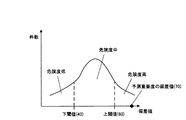
図22は、危険度の判定例を示す図である。図22には、障害履歴管理表121内の全レコードの重要度の偏差値分布を示している。横軸が偏差値、縦軸が該当する偏差値の重要度が設定されたレコードの件数である。図22の例では、危険度判定の下閾値が「40」、上閾値が「60」である。この場合、予測重要度の偏差値が40未満であれば、危険度が低いと判定される。また予測重要度の偏差値が40以上60未満であれば、危険度が中程度と判定される。さらに予測重要度の偏差値が60以上であれば、危険度が高いと判定される。例えば、予測重要度の偏差値が70の場合、危険度が高いと判定される。 FIG. 22 is a diagram illustrating an example of determining the degree of risk. FIG. 22 shows a deviation distribution of importance levels of all records in the failure history management table 121. The horizontal axis is the deviation value, and the vertical axis is the number of records in which the importance of the corresponding deviation value is set. In the example of FIG. 22, the lower threshold for risk determination is “40”, and the upper threshold is “60”. In this case, if the deviation value of the predicted importance is less than 40, it is determined that the degree of risk is low. If the deviation value of the predicted importance is 40 or more and less than 60, the degree of risk is determined to be medium. Further, if the deviation value of the predicted importance is 60 or more, it is determined that the degree of risk is high. For example, when the deviation value of the predicted importance is 70, it is determined that the degree of risk is high.
危険度の判定結果は、危険度表示部144によりU/I130を介したモニタ21に表示される。その結果、変更予定情報を入力した管理者は、その変更予定情報に示した設定変更を実施することによる危険度を認識することができる。
The determination result of the risk level is displayed on the
図23は、変更予定情報の入力から危険度表示への画面遷移例を示す図である。例えば管理者が変更予定情報を入力する場合、モニタ21には変更予定情報入力画面81が表示される。
FIG. 23 is a diagram illustrating an example of screen transition from the input of the change schedule information to the risk level display. For example, when the administrator inputs change schedule information, a change schedule information input screen 81 is displayed on the
変更予定情報入力画面81には、複数のテキストボックス81a〜81dとボタン81eとが設けられている。テキストボックス81aは、対象ホスト名の入力領域である。テキストボックス81bは、設定対象のファイルのファイルパスの入力領域である。テキストボックス81cは、設定対象の設定情報の名称(設定項目名)の入力領域である。テキストボックス81dは、設定予定値の入力領域である。ボタン81eは、危険度の予測処理の実行を指示するボタンである。
The change schedule information input screen 81 is provided with a plurality of
管理者は、テキストボックス81a〜81dに変更内容を入力し、入力が完了したらボタン81eを押下する。ボタン81eが押下されると、管理装置100において、各テキストボックスへの入力内容で指定された設定変更を行った場合の危険度が予測される。
The administrator inputs the change contents in the
なおホスト名、設定ファイルパス、設定項目名の入力は、テキストボックスに代えてセレクトボックスで行うこともできる。例えばセレクトボックスでは、入力候補となる情報がプルダウンメニューで表示される。管理者は、プルダウンメニューに表示された候補の中から、入力する情報を選択することができる。 Note that the host name, setting file path, and setting item name can be entered in the select box instead of the text box. For example, in the select box, input candidate information is displayed in a pull-down menu. The administrator can select input information from candidates displayed in the pull-down menu.
危険度が判定されると、判定結果を示す危険度表示画面82〜84がモニタ21に表示される。各危険度表示画面82〜84には、危険度を示すシグナル82a,83a,84aが設けられている。シグナル82a,83a,84aは、危険度に応じた色をしている。例えば危険度「高」を示すシグナル82aは、赤色の点灯もしくは点滅表示である。また危険度「中」を示すシグナル83aは、例えば黄色の点灯もしくは点滅表示である。さら危険度「低」を示すシグナル84aは、例えば緑色の点灯である。ここに例示したシグナル82a,83a,84aの色は、信号機の色と同じである。このような色で危険度を表示することで、管理者に対して、設定変更による障害の危険性を、直感的に認識させることができる。
When the risk level is determined, risk level display screens 82 to 84 showing the determination results are displayed on the
また危険度表示画面82〜84には、危険度を示すメッセージ表示部82b,83b,84bが表示されている。例えば危険度「高」の危険度表示画面82のメッセージ表示部82bには、「危険度:高(要再検討)」と表示される。また危険度「中」の危険度表示画面83のメッセージ表示部83bには、「危険度:中(要注意)」と表示される。さらに危険度「低」の危険度表示画面84のメッセージ表示部84bには、「危険度:低(安全)」と表示される。このようなメッセージの表示により、管理者は、危険の程度を容易に認識することができる。
On the risk level display screens 82 to 84,
このようにして、危険度の高さを分かりやすく表示することができる。その結果、管理者は、設定変更を行う前に、危険度に応じた対応策を講じることができる。しかも第2の実施の形態では、同種の設定情報の設定値を変更したことによる障害発生事例が過去になくても、適切な危険度を判定可能である。なお、同種の設定情報の設定値を変更したことによる障害発生事例がある場合、その事例に関する履歴情報も利用して予測重要度が計算される。これにより、重要度の予測精度が向上する。 In this way, the level of danger can be displayed in an easy-to-understand manner. As a result, the administrator can take countermeasures according to the degree of risk before changing the setting. Moreover, in the second embodiment, it is possible to determine an appropriate degree of risk even if there has not been a failure occurrence case in the past due to a change in the setting value of the same type of setting information. Note that, when there is a failure occurrence case due to a change in the setting value of the same type of setting information, the prediction importance is calculated using history information regarding the case. Thereby, the prediction accuracy of importance improves.
なお、上記の障害履歴管理DB120には、障害が発生した設定変更に関する履歴情報を格納しているが、障害が発生しなかった設定変更に関する履歴情報を、障害履歴管理DB120に登録してもよい。その場合、例えば重要度0としたレコードが障害履歴管理表121に登録される。障害が発生していない場合の履歴情報を登録しておくことで、障害が発生しない設定変更の回数に応じて、予測重要度の値が変化する。例えば障害が発生していない履歴情報(重要度「0」)が関連障害履歴として多数抽出された場合、重要度の平均は低くなり、予測重要度の値が小さくなる。
The failure
また第2の実施の形態では、サーバ41,42,43,・・・の設定情報を変更する場合の例を詳細に説明したが、第2の実施の形態の処理は、ストレージ装置51,52,・・・の設定情報を変更する場合にも同様に適用できる。さらに第2の実施の形態の処理は、スイッチなどの各種機器の設定変更にも適用可能である。
In the second embodiment, the example in which the setting information of the
以上、実施の形態を例示したが、実施の形態で示した各部の構成は同様の機能を有する他のものに置換することができる。また、他の任意の構成物や工程が付加されてもよい。さらに、前述した実施の形態のうちの任意の2以上の構成(特徴)を組み合わせたものであってもよい。 As mentioned above, although embodiment was illustrated, the structure of each part shown by embodiment can be substituted by the other thing which has the same function. Moreover, other arbitrary structures and processes may be added. Further, any two or more configurations (features) of the above-described embodiments may be combined.
1 変更予定情報
2,3a,3b,4a,4b 集合
10 情報処理装置
11 記憶手段
12 決定手段
13 取得手段
14 予測手段
1
Claims (10)
コンピュータに、
特定の集合に属する装置のうちの第1の割合の装置の設定情報の変更予定を示す変更予定情報に基づいて、同一集合に属する装置のうちの少なくとも一部の装置の設定情報を変更したときの内容を含む履歴情報を記憶する記憶手段から、同一集合に属する装置のうちの、前記第1の割合と所定の類似関係を満たす第2の割合の装置の設定情報を変更したときの履歴情報を取得し、
取得した該履歴情報に基づいて、前記変更予定情報に示される設定情報の変更を行うことによる前記システムへの影響を予測する、
処理を実行させることを特徴とする管理プログラム。 A management program for managing a system having a plurality of devices classified into a plurality of sets,
On the computer,
When the setting information of at least some of the devices belonging to the same set is changed based on the change schedule information indicating the change schedule of the setting information of the first proportion of devices belonging to the specific set History information when the setting information of the second proportion of devices that satisfy a predetermined similarity relationship with the first proportion of the devices belonging to the same set is changed from the storage means that stores the history information including the contents of Get
Based on the acquired history information, predict the influence on the system by changing the setting information shown in the change schedule information,
A management program characterized by causing processing to be executed.
前記変更予定情報には、設定変更対象の少なくとも1つの装置、および値を変更する設定情報の種別が指定されており、
前記コンピュータに、さらに、
前記変更予定情報に基づいて、値を変更する設定情報の種別に適用されるルールに示される階層の集合のうち、該少なくとも1つの装置が共に属する集合を特定し、該集合に属する装置に対する、該少なくとも1つの装置の割合を、前記第1の割合と決定する、
処理を実行させることを特徴とする請求項1記載の管理プログラム。 The plurality of devices in the system are classified into a set of hierarchical structures, and for each type of setting information, a rule is defined regarding which set of hierarchies the value of setting information is shared with,
In the change schedule information, at least one device to be changed and a type of setting information whose value is changed are specified,
In addition to the computer,
Based on the change schedule information, among the set of hierarchies shown in the rule applied to the type of setting information whose value is to be changed, the set to which the at least one device belongs together is specified, and for the devices belonging to the set, Determining a proportion of the at least one device as the first proportion;
The management program according to claim 1, wherein the management program is executed.
ことを特徴とする請求項1または2に記載の管理プログラム。 In the acquisition of history information, the history information when the setting information of the same type as the setting information whose value is changed is further acquired from the storage means.
The management program according to claim 1 or 2, characterized in that.
ことを特徴とする請求項1乃至3のいずれかに記載の管理プログラム。 In the prediction of the impact, the history information having a higher similarity between the first ratio and the second ratio reflects the contents of the history information more strongly in the prediction.
The management program according to any one of claims 1 to 3, wherein
ことを特徴とする請求項1乃至4のいずれかに記載の管理プログラム。 In the acquisition of history information, among the setting information of each device belonging to the specific set, the setting information of the same type as the setting information whose value is changed is compared, the degree of deviation from the rule is calculated, and the calculation result is calculated. Used to determine whether the predetermined similarity relationship is satisfied,
The management program according to claim 1, wherein:
前記影響の予測では、前記システムへの影響の度合いを予測する、
ことを特徴とする請求項1乃至5のいずれかに記載の管理プログラム。 The history information stored in the storage means indicates the degree of influence on the system when the setting information of at least some of the devices belonging to the same set is changed,
In the impact prediction, the degree of impact on the system is predicted.
The management program according to any one of claims 1 to 5, wherein
影響の予測では、取得した履歴情報に示される重要度に基づいて、予定されている設定変更を実施することによる影響度合いを予測する、
ことを特徴とする請求項6記載の管理プログラム。 The history information stored in the storage means includes the importance of the failure caused by the change of the setting information,
In the impact prediction, based on the importance shown in the acquired history information, predict the impact level by implementing the planned setting change,
The management program according to claim 6.
ことを特徴とする請求項7記載の管理プログラム。 In the impact prediction, based on the importance shown in the acquired history information, the importance of the failure that occurs due to the scheduled change of settings is predicted, and the importance distribution shown in the acquired history information From this, the deviation value of the predicted importance is calculated, and by comparing the deviation value with a predetermined threshold value, the rank of the risk of setting change scheduled is determined.
8. The management program according to claim 7, wherein:
コンピュータが、
特定の集合に属する装置のうちの第1の割合の装置の設定情報の変更予定を示す変更予定情報に基づいて、同一集合に属する装置のうちの少なくとも一部の装置の設定情報を変更したときの内容を含む履歴情報を記憶する記憶手段から、同一集合に属する装置のうちの、前記第1の割合と所定の類似関係を満たす第2の割合の装置の設定情報を変更したときの履歴情報を取得し、
取得した該履歴情報に基づいて、前記変更予定情報に示される設定情報の変更を行うことによる前記システムへの影響を予測する、
処理を実行させることを特徴とする管理方法。 A management method for managing a system having a plurality of devices classified into a plurality of sets,
Computer
When the setting information of at least some of the devices belonging to the same set is changed based on the change schedule information indicating the change schedule of the setting information of the first proportion of devices belonging to the specific set History information when the setting information of the second proportion of devices that satisfy a predetermined similarity relationship with the first proportion of the devices belonging to the same set is changed from the storage means that stores the history information including the contents of Get
Based on the acquired history information, predict the influence on the system by changing the setting information shown in the change schedule information,
A management method characterized by causing a process to be executed.
特定の集合に属する装置のうちの第1の割合の装置の設定情報の変更予定を示す変更予定情報に基づいて、同一集合に属する装置のうちの少なくとも一部の装置の設定情報を変更したときの内容を含む履歴情報を記憶する記憶手段から、同一集合に属する装置のうちの、前記第1の割合と所定の類似関係を満たす第2の割合の装置の設定情報を変更したときの履歴情報を取得する取得手段と、
取得した該履歴情報に基づいて、前記変更予定情報に示される設定情報の変更を行うことによる前記システムへの影響を予測する予測手段と、
を有する情報処理装置。 An information processing apparatus for managing a system having a plurality of devices classified into a plurality of sets,
When the setting information of at least some of the devices belonging to the same set is changed based on the change schedule information indicating the change schedule of the setting information of the first proportion of devices belonging to the specific set History information when the setting information of the second proportion of devices that satisfy a predetermined similarity relationship with the first proportion of the devices belonging to the same set is changed from the storage means that stores the history information including the contents of Obtaining means for obtaining
Prediction means for predicting the influence on the system by changing the setting information indicated in the change schedule information based on the acquired history information;
An information processing apparatus.
Priority Applications (2)
| Application Number | Priority Date | Filing Date | Title |
|---|---|---|---|
| JP2013209889A JP6152770B2 (en) | 2013-10-07 | 2013-10-07 | Management program, management method, and information processing apparatus |
| US14/505,219 US20150100579A1 (en) | 2013-10-07 | 2014-10-02 | Management method and information processing apparatus |
Applications Claiming Priority (1)
| Application Number | Priority Date | Filing Date | Title |
|---|---|---|---|
| JP2013209889A JP6152770B2 (en) | 2013-10-07 | 2013-10-07 | Management program, management method, and information processing apparatus |
Publications (2)
| Publication Number | Publication Date |
|---|---|
| JP2015075807A JP2015075807A (en) | 2015-04-20 |
| JP6152770B2 true JP6152770B2 (en) | 2017-06-28 |
Family
ID=52777829
Family Applications (1)
| Application Number | Title | Priority Date | Filing Date |
|---|---|---|---|
| JP2013209889A Expired - Fee Related JP6152770B2 (en) | 2013-10-07 | 2013-10-07 | Management program, management method, and information processing apparatus |
Country Status (2)
| Country | Link |
|---|---|
| US (1) | US20150100579A1 (en) |
| JP (1) | JP6152770B2 (en) |
Families Citing this family (9)
| Publication number | Priority date | Publication date | Assignee | Title |
|---|---|---|---|---|
| US10084645B2 (en) * | 2015-11-30 | 2018-09-25 | International Business Machines Corporation | Estimating server-change risk by corroborating historic failure rates, predictive analytics, and user projections |
| US10310933B2 (en) * | 2017-01-13 | 2019-06-04 | Bank Of America Corporation | Near real-time system or network incident detection |
| US10191736B2 (en) * | 2017-04-28 | 2019-01-29 | Servicenow, Inc. | Systems and methods for tracking configuration file changes |
| JP6977367B2 (en) * | 2017-07-27 | 2021-12-08 | 富士フイルムビジネスイノベーション株式会社 | Program and article editing support device |
| CN108923952B (en) * | 2018-05-31 | 2021-11-30 | 北京百度网讯科技有限公司 | Fault diagnosis method, equipment and storage medium based on service monitoring index |
| US11036561B2 (en) * | 2018-07-24 | 2021-06-15 | Oracle International Corporation | Detecting device utilization imbalances |
| JP7240348B2 (en) * | 2020-03-06 | 2023-03-15 | 株式会社日立製作所 | Computer system and application data allocation control method |
| CN113950075A (en) * | 2020-07-17 | 2022-01-18 | 华为技术有限公司 | Prediction method and terminal equipment |
| GB202210783D0 (en) * | 2022-07-22 | 2022-09-07 | Microsoft Technology Licensing Llc | Deploying a change to a network service |
Family Cites Families (5)
| Publication number | Priority date | Publication date | Assignee | Title |
|---|---|---|---|---|
| JP4896573B2 (en) * | 2006-04-20 | 2012-03-14 | 株式会社東芝 | Fault monitoring system and method, and program |
| JP2008234617A (en) * | 2007-02-23 | 2008-10-02 | Matsushita Electric Works Ltd | Facility monitoring system and monitoring device |
| US8166552B2 (en) * | 2008-09-12 | 2012-04-24 | Hytrust, Inc. | Adaptive configuration management system |
| WO2010112960A1 (en) * | 2009-03-30 | 2010-10-07 | Hitachi, Ltd. | Method and apparatus for cause analysis involving configuration changes |
| US9298538B2 (en) * | 2012-08-16 | 2016-03-29 | Vmware, Inc. | Methods and systems for abnormality analysis of streamed log data |
-
2013
- 2013-10-07 JP JP2013209889A patent/JP6152770B2/en not_active Expired - Fee Related
-
2014
- 2014-10-02 US US14/505,219 patent/US20150100579A1/en not_active Abandoned
Also Published As
| Publication number | Publication date |
|---|---|
| US20150100579A1 (en) | 2015-04-09 |
| JP2015075807A (en) | 2015-04-20 |
Similar Documents
| Publication | Publication Date | Title |
|---|---|---|
| JP6152770B2 (en) | Management program, management method, and information processing apparatus | |
| US9690645B2 (en) | Determining suspected root causes of anomalous network behavior | |
| US9124488B2 (en) | Method and apparatus for visualizing the health of datacenter objects | |
| KR101971013B1 (en) | Cloud infra real time analysis system based on big date and the providing method thereof | |
| US20160378583A1 (en) | Management computer and method for evaluating performance threshold value | |
| JP6387777B2 (en) | Evaluation program, evaluation method, and evaluation apparatus | |
| US20170063709A1 (en) | Methods and apparatus to manage and execute actions in computing environments | |
| US10108455B2 (en) | Methods and apparatus to manage and execute actions in computing environments based on a type of virtual compute node | |
| US20170261403A1 (en) | Abnormality detection procedure development apparatus and abnormality detection procedure development method | |
| US20140122691A1 (en) | Determining root causes of network issues | |
| US10659312B2 (en) | Network anomaly detection | |
| US9736031B2 (en) | Information system construction assistance device, information system construction assistance method, and information system construction assistance program | |
| US9696982B1 (en) | Safe host deployment for a heterogeneous host fleet | |
| US11416321B2 (en) | Component failure prediction | |
| JP2018180759A (en) | System analysis system and system analysis method | |
| US9860109B2 (en) | Automatic alert generation | |
| US20170063710A1 (en) | Methods and apparatus to manage and execute actions in computing environments | |
| US20150248508A1 (en) | Information system construction device, information system construction method, and storage medium | |
| US20200175380A1 (en) | Automated feature generation for sensor subset selection | |
| CN114270391A (en) | Quantifying privacy impact | |
| US20150261647A1 (en) | Information system construction assistance device, information system construction assistance method, and recording medium | |
| US9760611B2 (en) | Identifying element relationships in a document | |
| JP7032640B2 (en) | Impact range identification program, impact range identification method, and impact range identification device | |
| TWI669675B (en) | Analysis control method and analysis control device for time series data | |
| CN112817869A (en) | Test method, test device, test medium, and electronic apparatus |
Legal Events
| Date | Code | Title | Description |
|---|---|---|---|
| A621 | Written request for application examination |
Free format text: JAPANESE INTERMEDIATE CODE: A621 Effective date: 20160606 |
|
| A977 | Report on retrieval |
Free format text: JAPANESE INTERMEDIATE CODE: A971007 Effective date: 20170425 |
|
| TRDD | Decision of grant or rejection written | ||
| A01 | Written decision to grant a patent or to grant a registration (utility model) |
Free format text: JAPANESE INTERMEDIATE CODE: A01 Effective date: 20170502 |
|
| A61 | First payment of annual fees (during grant procedure) |
Free format text: JAPANESE INTERMEDIATE CODE: A61 Effective date: 20170515 |
|
| R150 | Certificate of patent or registration of utility model |
Ref document number: 6152770 Country of ref document: JP Free format text: JAPANESE INTERMEDIATE CODE: R150 |
|
| LAPS | Cancellation because of no payment of annual fees |