JP6140773B2 - Electronic device and method of operating electronic device - Google Patents

Electronic device and method of operating electronic device Download PDF

Info

Publication number
JP6140773B2
JP6140773B2 JP2015128722A JP2015128722A JP6140773B2 JP 6140773 B2 JP6140773 B2 JP 6140773B2 JP 2015128722 A JP2015128722 A JP 2015128722A JP 2015128722 A JP2015128722 A JP 2015128722A JP 6140773 B2 JP6140773 B2 JP 6140773B2
Authority
JP
Japan
Prior art keywords
electronic device
finger
fingerprint
user
control unit
Prior art date
Legal status (The legal status is an assumption and is not a legal conclusion. Google has not performed a legal analysis and makes no representation as to the accuracy of the status listed.)
Active
Application number
JP2015128722A
Other languages
Japanese (ja)
Other versions
JP2017016170A (en
Inventor
健史 島田
健史 島田
悠斗 石田
悠斗 石田
Current Assignee (The listed assignees may be inaccurate. Google has not performed a legal analysis and makes no representation or warranty as to the accuracy of the list.)
Kyocera Corp
Original Assignee
Kyocera Corp
Priority date (The priority date is an assumption and is not a legal conclusion. Google has not performed a legal analysis and makes no representation as to the accuracy of the date listed.)
Filing date
Publication date
Application filed by Kyocera Corp filed Critical Kyocera Corp
Priority to JP2015128722A priority Critical patent/JP6140773B2/en
Priority to PCT/JP2016/068348 priority patent/WO2016208564A1/en
Publication of JP2017016170A publication Critical patent/JP2017016170A/en
Application granted granted Critical
Publication of JP6140773B2 publication Critical patent/JP6140773B2/en
Priority to US15/849,447 priority patent/US20180114046A1/en
Active legal-status Critical Current
Anticipated expiration legal-status Critical

Links

Images

Classifications

    • GPHYSICS
    • G06COMPUTING; CALCULATING OR COUNTING
    • G06FELECTRIC DIGITAL DATA PROCESSING
    • G06F1/00Details not covered by groups G06F3/00 - G06F13/00 and G06F21/00
    • G06F1/16Constructional details or arrangements
    • G06F1/1613Constructional details or arrangements for portable computers
    • G06F1/1626Constructional details or arrangements for portable computers with a single-body enclosure integrating a flat display, e.g. Personal Digital Assistants [PDAs]
    • GPHYSICS
    • G06COMPUTING; CALCULATING OR COUNTING
    • G06FELECTRIC DIGITAL DATA PROCESSING
    • G06F1/00Details not covered by groups G06F3/00 - G06F13/00 and G06F21/00
    • G06F1/16Constructional details or arrangements
    • G06F1/1613Constructional details or arrangements for portable computers
    • G06F1/1633Constructional details or arrangements of portable computers not specific to the type of enclosures covered by groups G06F1/1615 - G06F1/1626
    • G06F1/1684Constructional details or arrangements related to integrated I/O peripherals not covered by groups G06F1/1635 - G06F1/1675
    • G06F1/169Constructional details or arrangements related to integrated I/O peripherals not covered by groups G06F1/1635 - G06F1/1675 the I/O peripheral being an integrated pointing device, e.g. trackball in the palm rest area, mini-joystick integrated between keyboard keys, touch pads or touch stripes
    • GPHYSICS
    • G06COMPUTING; CALCULATING OR COUNTING
    • G06FELECTRIC DIGITAL DATA PROCESSING
    • G06F21/00Security arrangements for protecting computers, components thereof, programs or data against unauthorised activity
    • G06F21/30Authentication, i.e. establishing the identity or authorisation of security principals
    • G06F21/31User authentication
    • G06F21/32User authentication using biometric data, e.g. fingerprints, iris scans or voiceprints
    • GPHYSICS
    • G06COMPUTING; CALCULATING OR COUNTING
    • G06FELECTRIC DIGITAL DATA PROCESSING
    • G06F3/00Input arrangements for transferring data to be processed into a form capable of being handled by the computer; Output arrangements for transferring data from processing unit to output unit, e.g. interface arrangements
    • G06F3/01Input arrangements or combined input and output arrangements for interaction between user and computer
    • G06F3/03Arrangements for converting the position or the displacement of a member into a coded form
    • G06F3/033Pointing devices displaced or positioned by the user, e.g. mice, trackballs, pens or joysticks; Accessories therefor
    • G06F3/0354Pointing devices displaced or positioned by the user, e.g. mice, trackballs, pens or joysticks; Accessories therefor with detection of 2D relative movements between the device, or an operating part thereof, and a plane or surface, e.g. 2D mice, trackballs, pens or pucks
    • G06F3/03547Touch pads, in which fingers can move on a surface
    • GPHYSICS
    • G06COMPUTING; CALCULATING OR COUNTING
    • G06FELECTRIC DIGITAL DATA PROCESSING
    • G06F3/00Input arrangements for transferring data to be processed into a form capable of being handled by the computer; Output arrangements for transferring data from processing unit to output unit, e.g. interface arrangements
    • G06F3/01Input arrangements or combined input and output arrangements for interaction between user and computer
    • G06F3/048Interaction techniques based on graphical user interfaces [GUI]
    • G06F3/0481Interaction techniques based on graphical user interfaces [GUI] based on specific properties of the displayed interaction object or a metaphor-based environment, e.g. interaction with desktop elements like windows or icons, or assisted by a cursor's changing behaviour or appearance
    • G06F3/0482Interaction with lists of selectable items, e.g. menus
    • GPHYSICS
    • G06COMPUTING; CALCULATING OR COUNTING
    • G06FELECTRIC DIGITAL DATA PROCESSING
    • G06F3/00Input arrangements for transferring data to be processed into a form capable of being handled by the computer; Output arrangements for transferring data from processing unit to output unit, e.g. interface arrangements
    • G06F3/01Input arrangements or combined input and output arrangements for interaction between user and computer
    • G06F3/048Interaction techniques based on graphical user interfaces [GUI]
    • G06F3/0484Interaction techniques based on graphical user interfaces [GUI] for the control of specific functions or operations, e.g. selecting or manipulating an object, an image or a displayed text element, setting a parameter value or selecting a range
    • G06F3/0485Scrolling or panning
    • GPHYSICS
    • G06COMPUTING; CALCULATING OR COUNTING
    • G06FELECTRIC DIGITAL DATA PROCESSING
    • G06F3/00Input arrangements for transferring data to be processed into a form capable of being handled by the computer; Output arrangements for transferring data from processing unit to output unit, e.g. interface arrangements
    • G06F3/01Input arrangements or combined input and output arrangements for interaction between user and computer
    • G06F3/048Interaction techniques based on graphical user interfaces [GUI]
    • G06F3/0487Interaction techniques based on graphical user interfaces [GUI] using specific features provided by the input device, e.g. functions controlled by the rotation of a mouse with dual sensing arrangements, or of the nature of the input device, e.g. tap gestures based on pressure sensed by a digitiser
    • G06F3/0488Interaction techniques based on graphical user interfaces [GUI] using specific features provided by the input device, e.g. functions controlled by the rotation of a mouse with dual sensing arrangements, or of the nature of the input device, e.g. tap gestures based on pressure sensed by a digitiser using a touch-screen or digitiser, e.g. input of commands through traced gestures
    • G06F3/04883Interaction techniques based on graphical user interfaces [GUI] using specific features provided by the input device, e.g. functions controlled by the rotation of a mouse with dual sensing arrangements, or of the nature of the input device, e.g. tap gestures based on pressure sensed by a digitiser using a touch-screen or digitiser, e.g. input of commands through traced gestures for inputting data by handwriting, e.g. gesture or text
    • GPHYSICS
    • G06COMPUTING; CALCULATING OR COUNTING
    • G06VIMAGE OR VIDEO RECOGNITION OR UNDERSTANDING
    • G06V10/00Arrangements for image or video recognition or understanding
    • G06V10/20Image preprocessing
    • G06V10/24Aligning, centring, orientation detection or correction of the image
    • G06V10/242Aligning, centring, orientation detection or correction of the image by image rotation, e.g. by 90 degrees
    • GPHYSICS
    • G06COMPUTING; CALCULATING OR COUNTING
    • G06VIMAGE OR VIDEO RECOGNITION OR UNDERSTANDING
    • G06V40/00Recognition of biometric, human-related or animal-related patterns in image or video data
    • G06V40/10Human or animal bodies, e.g. vehicle occupants or pedestrians; Body parts, e.g. hands
    • G06V40/12Fingerprints or palmprints
    • G06V40/1347Preprocessing; Feature extraction
    • G06V40/1359Extracting features related to ridge properties; Determining the fingerprint type, e.g. whorl or loop
    • GPHYSICS
    • G06COMPUTING; CALCULATING OR COUNTING
    • G06VIMAGE OR VIDEO RECOGNITION OR UNDERSTANDING
    • G06V40/00Recognition of biometric, human-related or animal-related patterns in image or video data
    • G06V40/10Human or animal bodies, e.g. vehicle occupants or pedestrians; Body parts, e.g. hands
    • G06V40/12Fingerprints or palmprints
    • G06V40/1365Matching; Classification
    • G06V40/1376Matching features related to ridge properties or fingerprint texture
    • HELECTRICITY
    • H04ELECTRIC COMMUNICATION TECHNIQUE
    • H04MTELEPHONIC COMMUNICATION
    • H04M1/00Substation equipment, e.g. for use by subscribers
    • HELECTRICITY
    • H04ELECTRIC COMMUNICATION TECHNIQUE
    • H04MTELEPHONIC COMMUNICATION
    • H04M1/00Substation equipment, e.g. for use by subscribers
    • H04M1/66Substation equipment, e.g. for use by subscribers with means for preventing unauthorised or fraudulent calling
    • H04M1/667Preventing unauthorised calls from a telephone set
    • H04M1/67Preventing unauthorised calls from a telephone set by electronic means
    • HELECTRICITY
    • H04ELECTRIC COMMUNICATION TECHNIQUE
    • H04MTELEPHONIC COMMUNICATION
    • H04M1/00Substation equipment, e.g. for use by subscribers
    • H04M1/72Mobile telephones; Cordless telephones, i.e. devices for establishing wireless links to base stations without route selection
    • H04M1/724User interfaces specially adapted for cordless or mobile telephones
    • H04M1/72403User interfaces specially adapted for cordless or mobile telephones with means for local support of applications that increase the functionality
    • GPHYSICS
    • G06COMPUTING; CALCULATING OR COUNTING
    • G06FELECTRIC DIGITAL DATA PROCESSING
    • G06F2203/00Indexing scheme relating to G06F3/00 - G06F3/048
    • G06F2203/033Indexing scheme relating to G06F3/033
    • G06F2203/0338Fingerprint track pad, i.e. fingerprint sensor used as pointing device tracking the fingertip image
    • GPHYSICS
    • G06COMPUTING; CALCULATING OR COUNTING
    • G06FELECTRIC DIGITAL DATA PROCESSING
    • G06F2203/00Indexing scheme relating to G06F3/00 - G06F3/048
    • G06F2203/033Indexing scheme relating to G06F3/033
    • G06F2203/0339Touch strips, e.g. orthogonal touch strips to control cursor movement or scrolling; single touch strip to adjust parameter or to implement a row of soft keys
    • HELECTRICITY
    • H04ELECTRIC COMMUNICATION TECHNIQUE
    • H04MTELEPHONIC COMMUNICATION
    • H04M2250/00Details of telephonic subscriber devices
    • H04M2250/22Details of telephonic subscriber devices including a touch pad, a touch sensor or a touch detector

Description

本発明は、電子機器に関する。   The present invention relates to an electronic device.

特許文献1に記載されているように、電子機器に関して様々な技術が提案されている。   As described in Patent Document 1, various techniques have been proposed for electronic devices.

特開平11−212689号公報Japanese Patent Laid-Open No. 11-212589

電子機器については、その操作性の向上が望まれる。   For electronic devices, improvement in operability is desired.

そこで、本発明は上述の点に鑑みて成されたものであり、電子機器の操作性を向上することが可能な技術を提供することを目的とする。   Therefore, the present invention has been made in view of the above-described points, and an object thereof is to provide a technique capable of improving the operability of an electronic device.

電子機器及び電子機器の動作方法が開示される。一の実施の形態では、電子機器は、指紋センサ、強さ判定部及び処理部を備える。指紋センサは、ユーザの指によって触られる所定領域を有し、当該所定領域を触る指の指紋を検出する。強さ判定部は、指紋センサでの指紋検出結果に基づいて、所定領域に対する指の押圧の強さを判定する。処理部は、強さ判定部で判定された強さに応じて、実行する処理を変化させる。   An electronic device and a method for operating the electronic device are disclosed. In one embodiment, an electronic device includes a fingerprint sensor, a strength determination unit, and a processing unit. The fingerprint sensor has a predetermined area touched by the user's finger and detects a fingerprint of the finger touching the predetermined area. The strength determination unit determines the strength of the finger pressing on the predetermined area based on the fingerprint detection result by the fingerprint sensor. The processing unit changes the process to be executed according to the strength determined by the strength determination unit.

また一の実施の形態では、電子機器は、指紋センサ、認証処理部、押しボタン及び処理部を備える。指紋センサは、ユーザの指によって触られる所定領域を有し、当該所定領域を触る指の指紋を検出する。認証処理部は、指紋センサでの指紋検出結果に基づいて、ユーザ認証を行う。押しボタンは、ユーザによって操作される操作領域を有する。処理部は、ユーザ認証が成功したときカメラプリケーションを実行する。所定領域は、操作領域に含まれる。処理部は、カメラアプリケーションの実行中において、所定領域がユーザの指によって触られる状態がユーザ認証の開始から継続しているときには、押しボタンをシャッタボタンとして機能させる。 In one embodiment, an electronic device includes a fingerprint sensor, an authentication processing unit, a push button, and a processing unit. The fingerprint sensor has a predetermined area touched by the user's finger and detects a fingerprint of the finger touching the predetermined area. The authentication processing unit performs user authentication based on the result of fingerprint detection by the fingerprint sensor. The push button has an operation area operated by the user. The processing unit executes the camera application when the user authentication is successful. The predetermined area is included in the operation area. The processing unit causes the push button to function as a shutter button when the state in which the predetermined area is touched by the user's finger continues from the start of user authentication during the execution of the camera application.

また、一の実施の形態では、電子機器の動作方法は、ユーザの指によって触られる所定領域を有し、当該所定領域を触る指の指紋を検出する指紋センサを有する電子機器の動作方法である。電子機器の動作方法は、指紋センサでの指紋検出結果に基づいて、所定領域に対する指の押圧の強さを判定する工程と、当該強さに応じて、実行する処理を変化させる工程とを備える。   In one embodiment, the operation method of the electronic device is a method of operating an electronic device having a predetermined area touched by a user's finger and having a fingerprint sensor that detects a fingerprint of the finger touching the predetermined area. . The operation method of the electronic device includes a step of determining the strength of pressing the finger against a predetermined region based on a fingerprint detection result by the fingerprint sensor, and a step of changing a process to be executed according to the strength. .

また、一の実施の形態では、電子機器の動作方法は、ユーザの指によって触られる所定領域を有し、当該所定領域を触る指の指紋を検出する指紋センサと、ユーザによって操作される操作領域を有する押しボタンとを備え、所定領域が操作領域に含まれる電子機器の動作方法である。電子機器の動作方法は、指紋センサでの指紋検出結果に基づいて、ユーザ認証を行う工程と、ユーザ認証が成功したときカメラプリケーションを実行する工程と、カメラアプリケーションの実行中において、所定領域がユーザの指によって触られる状態がユーザ認証の開始から継続しているときには、押しボタンをシャッタボタンとして機能させる工程とを備える。
In one embodiment, an electronic device operating method includes a fingerprint sensor that has a predetermined area touched by a user's finger and detects a fingerprint of the finger that touches the predetermined area, and an operation area operated by the user. And an operation method of an electronic device in which a predetermined area is included in the operation area . The operation method of the electronic device includes a step of performing user authentication based on a fingerprint detection result by a fingerprint sensor, a step of executing a camera application when the user authentication is successful, and a predetermined area during execution of the camera application. And a step of causing the push button to function as a shutter button when the state touched by the user's finger continues from the start of user authentication .

電子機器の操作性が向上する。   The operability of electronic equipment is improved.

電子機器の外観を示す斜視図である。It is a perspective view which shows the external appearance of an electronic device. 電子機器の外観を示す前面図である。It is a front view which shows the external appearance of an electronic device. 電子機器の外観を示す背面図である。It is a rear view which shows the external appearance of an electronic device. 指紋検出範囲を示す図である。It is a figure which shows a fingerprint detection range. 電子機器の構成を示すブロック図である。It is a block diagram which shows the structure of an electronic device. 電子機器の表示の一例を示す図である。It is a figure which shows an example of the display of an electronic device. 電子機器の表示の一例を示す図である。It is a figure which shows an example of the display of an electronic device. 複数の基準特徴点テーブルを示す図である。It is a figure which shows a some reference | standard feature point table. 基準特徴点テーブルの一例を示す図である。It is a figure which shows an example of a reference | standard feature point table. 操作領域を触る指の向きの一例を示す図である。It is a figure which shows an example of direction of the finger | toe which touches an operation area | region. 操作領域を触る指の向きの一例を示す図である。It is a figure which shows an example of direction of the finger | toe which touches an operation area | region. 操作領域を触る指の向きの一例を示す図である。It is a figure which shows an example of direction of the finger | toe which touches an operation area | region. 操作領域を触る指の向きの一例を示す図である。It is a figure which shows an example of direction of the finger | toe which touches an operation area | region. 操作領域を触る指の向きの一例を示す図である。It is a figure which shows an example of direction of the finger | toe which touches an operation area | region. 操作領域を触る指の向きの一例を示す図である。It is a figure which shows an example of direction of the finger | toe which touches an operation area | region. 指紋センサで検出される指紋の一例を示す図である。It is a figure which shows an example of the fingerprint detected with a fingerprint sensor. 指紋センサで検出される指紋の一例を示す図である。It is a figure which shows an example of the fingerprint detected with a fingerprint sensor. 指紋センサで検出される指紋の一例を示す図である。It is a figure which shows an example of the fingerprint detected with a fingerprint sensor. 指紋センサで検出される指紋の一例を示す図である。It is a figure which shows an example of the fingerprint detected with a fingerprint sensor. 指紋センサで検出される指紋の一例を示す図である。It is a figure which shows an example of the fingerprint detected with a fingerprint sensor. 指紋センサで検出される指紋の一例を示す図である。It is a figure which shows an example of the fingerprint detected with a fingerprint sensor. 指紋センサで検出される指紋の一例を示す図である。It is a figure which shows an example of the fingerprint detected with a fingerprint sensor. 指紋センサで検出される指紋の一例を示す図である。It is a figure which shows an example of the fingerprint detected with a fingerprint sensor. 電子機器の表示の一例を示す図である。It is a figure which shows an example of the display of an electronic device. 電子機器の表示の一例を示す図である。It is a figure which shows an example of the display of an electronic device. 電子機器の表示の一例を示す図である。It is a figure which shows an example of the display of an electronic device. 電子機器の表示の一例を示す図である。It is a figure which shows an example of the display of an electronic device. 電子機器の動作を示すフローチャートである。It is a flowchart which shows operation | movement of an electronic device. 縦向きの電子機器が右手で操作される様子を示す図である。It is a figure which shows a mode that the electronic device of portrait orientation is operated with a right hand. 縦向きの電子機器が左手で操作される様子を示す図である。It is a figure which shows a mode that the electronic device of portrait orientation is operated with the left hand. 横向きの電子機器が右手で操作される様子を示す図である。It is a figure which shows a mode that a horizontal electronic device is operated with a right hand. 横向きの電子機器が左手で操作される様子を示す図である。It is a figure which shows a mode that a horizontal electronic device is operated with the left hand. 縦向きの電子機器が右手で操作される様子を示す図である。It is a figure which shows a mode that the electronic device of portrait orientation is operated with a right hand. 縦向きの電子機器が左手で操作される様子を示す図である。It is a figure which shows a mode that the electronic device of portrait orientation is operated with the left hand. 横向きの電子機器が右手で操作される様子を示す図である。It is a figure which shows a mode that a horizontal electronic device is operated with a right hand. 横向きの電子機器が左手で操作される様子を示す図である。It is a figure which shows a mode that a horizontal electronic device is operated with the left hand. 縦向きの電子機器が右手で操作される様子を示す図である。It is a figure which shows a mode that the electronic device of portrait orientation is operated with a right hand. 横向きの電子機器が右手で操作される様子を示す図である。It is a figure which shows a mode that a horizontal electronic device is operated with a right hand. 電子機器の操作領域に対するユーザ操作の一例を示す図である。It is a figure which shows an example of user operation with respect to the operation area | region of an electronic device. 電子機器の操作領域に対するユーザ操作の一例を示す図である。It is a figure which shows an example of user operation with respect to the operation area | region of an electronic device. 電子機器の操作領域に対するユーザ操作の一例を示す図である。It is a figure which shows an example of user operation with respect to the operation area | region of an electronic device. 電子機器の操作領域上で指が移動する様子の一例を示す図である。It is a figure which shows an example of a mode that a finger | toe moves on the operation area | region of an electronic device. 電子機器の操作領域に対するユーザ操作の一例を示す図である。It is a figure which shows an example of user operation with respect to the operation area | region of an electronic device. 電子機器の操作領域に対するユーザ操作の一例を示す図である。It is a figure which shows an example of user operation with respect to the operation area | region of an electronic device. 電子機器の操作領域に対するユーザ操作の一例を示す図である。It is a figure which shows an example of user operation with respect to the operation area | region of an electronic device. 電子機器の操作領域に対するユーザ操作の一例を示す図である。It is a figure which shows an example of user operation with respect to the operation area | region of an electronic device. 電子機器の操作領域に対するユーザ操作の一例を示す図である。It is a figure which shows an example of user operation with respect to the operation area | region of an electronic device. 電子機器の動作を示すフローチャートである。It is a flowchart which shows operation | movement of an electronic device. 電子機器の表示の一例を示す図である。It is a figure which shows an example of the display of an electronic device.

<電子機器の外観>
図1〜3は、それぞれ、電子機器1の外観を示す斜視図、前面図及び背面図である。図1〜3に示されるように、電子機器1は、平面視で略長方形の板状の機器ケース2を備えている。電子機器1の前面1a、つまり機器ケース2の前面には、文字、記号、図形等の各種情報が表示される表示領域20が設けられている。表示領域20の裏面には後述するタッチパネル130が貼り付けられている。これにより、ユーザは、電子機器1の前面1aの表示領域20を指等で操作することによって、電子機器1に対して各種情報を入力することができる。なお、ユーザは、指以外の操作子、例えば、スタイラスペンなどの静電式タッチパネル用ペンで表示領域20を操作することによっても、電子機器1に対して各種情報を入力することができる。また、タッチパネル130は表示領域20の前面に貼り付けられても良い。
<Appearance of electronic equipment>
1 to 3 are a perspective view, a front view, and a rear view, respectively, showing the external appearance of the electronic device 1. As shown in FIGS. 1 to 3, the electronic device 1 includes a plate-like device case 2 that is substantially rectangular in plan view. On the front surface 1a of the electronic device 1, that is, the front surface of the device case 2, a display area 20 is provided on which various information such as characters, symbols, and figures are displayed. A touch panel 130 described later is attached to the back surface of the display area 20. Thus, the user can input various information to the electronic device 1 by operating the display area 20 on the front surface 1a of the electronic device 1 with a finger or the like. Note that the user can also input various types of information to the electronic device 1 by operating the display area 20 with an operator other than a finger, for example, an electrostatic touch panel pen such as a stylus pen. The touch panel 130 may be attached to the front surface of the display area 20.

電子機器1は、第1側面1c、第2側面1d、第3側面1e及び第4側面1fを有している。第1側面1c及び第2側面1dは、電子機器1の長手方向(図2での上下方向)で対向しており、第3側面1e及び第4側面1fは、電子機器1の短手方向(図2での左右方向)で対向している。   The electronic device 1 has a first side surface 1c, a second side surface 1d, a third side surface 1e, and a fourth side surface 1f. The first side surface 1c and the second side surface 1d are opposed to each other in the longitudinal direction (vertical direction in FIG. 2) of the electronic device 1, and the third side surface 1e and the fourth side surface 1f are the short side direction of the electronic device 1 ( 2 in the left-right direction in FIG.

機器ケース2の前面における長手方向の両端部には、マイク穴23及びレシーバ穴22がそれぞれ設けられている。当該両端部において、第2側面1d側の端部にはマイク穴23が設けられ、第1側面1c側の端部にはレシーバ穴22が設けられている。   Microphone holes 23 and receiver holes 22 are respectively provided at both ends in the longitudinal direction on the front surface of the device case 2. At both ends, a microphone hole 23 is provided at the end on the second side 1d side, and a receiver hole 22 is provided at the end on the first side 1c side.

機器ケース2の前面における第1側面1c側の端部からは、後述する前面側撮像部190が有する撮像レンズ191が視認可能となっている。図3に示されるように、電子機器1の背面1b、つまり機器ケース2の背面には、スピーカ穴24が設けられている。機器ケース2の背面からは、後述する裏面側撮像部200が有する撮像レンズ201が視認可能となっている。   An imaging lens 191 included in a front-side imaging unit 190 described later is visible from an end of the device case 2 on the first side surface 1c side. As shown in FIG. 3, speaker holes 24 are provided on the back surface 1 b of the electronic device 1, that is, on the back surface of the device case 2. From the back surface of the device case 2, an imaging lens 201 included in a back surface side imaging unit 200 described later is visible.

機器ケース2の前面における第2側面1d側の端部には、ユーザの手の指によって操作される操作領域30が設けられている。操作領域30は、後述する押しボタン150の一部となっている。つまり、押しボタン150の一部が機器ケース2の前面における第2側面1d側の端部から露出しており、その露出部分が操作領域30となっている。ユーザは、操作領域30を押すことによって、押しボタン150を押すことができる。なお、操作領域30の位置及び形状は、図1,2に示される位置及び形状に限られない。   An operation region 30 that is operated by a finger of the user's hand is provided at the end of the device case 2 on the second side face 1d side. The operation area 30 is a part of a push button 150 described later. That is, a part of the push button 150 is exposed from the end portion on the second side surface 1 d side on the front surface of the device case 2, and the exposed portion is the operation region 30. The user can press the push button 150 by pressing the operation area 30. The position and shape of the operation area 30 are not limited to the position and shape shown in FIGS.

操作領域30の一部は、後述する指紋センサ140での指紋検出範囲141となっている。図4は指紋検出範囲141の一例を示す図である。指紋センサ140は、操作領域30に含まれる指紋検出範囲141を触るユーザの指500の指紋を検出することが可能である。なお、指紋検出範囲141は操作領域30と一致していても良い。また指紋検出範囲141の形状は図4の例には限られない。以後、指紋センサ140で検出された指紋を「検出指紋」と呼ぶことがある。また以下の説明では、操作領域30が指で触られることには、指紋検出範囲141が指で触れることも含む。   A part of the operation area 30 is a fingerprint detection range 141 in a fingerprint sensor 140 described later. FIG. 4 is a diagram illustrating an example of the fingerprint detection range 141. The fingerprint sensor 140 can detect the fingerprint of the user's finger 500 that touches the fingerprint detection range 141 included in the operation area 30. Note that the fingerprint detection range 141 may coincide with the operation area 30. The shape of the fingerprint detection range 141 is not limited to the example of FIG. Hereinafter, the fingerprint detected by the fingerprint sensor 140 may be referred to as “detected fingerprint”. In the following description, touching the operation area 30 with a finger includes touching the fingerprint detection range 141 with a finger.

<電子機器の電気的構成>
図5は電子機器1の電気的構成を主に示すブロック図である。図5に示されるように、電子機器1には、制御部100、無線通信部110、表示パネル120、タッチパネル130、指紋センサ140及び押しボタン150が設けられている。さらに電子機器1には、レシーバ160、外部スピーカ170、マイク180、前面側撮像部190及び裏面側撮像部200及び電池210が設けられている。電子機器1に設けられたこれらの構成要素は、機器ケース2内に収められている。
<Electrical configuration of electronic equipment>
FIG. 5 is a block diagram mainly showing an electrical configuration of the electronic apparatus 1. As shown in FIG. 5, the electronic device 1 is provided with a control unit 100, a wireless communication unit 110, a display panel 120, a touch panel 130, a fingerprint sensor 140, and a push button 150. Furthermore, the electronic device 1 is provided with a receiver 160, an external speaker 170, a microphone 180, a front side imaging unit 190, a back side imaging unit 200, and a battery 210. These components provided in the electronic device 1 are housed in the device case 2.

制御部100は、CPU(Central Processing Unit)101、DSP(Digital Signal Processor)102及び記憶部103等を備える制御回路である。制御部100は、電子機器1の他の構成要素を制御することによって、電子機器1の動作を統括的に管理する。   The control unit 100 is a control circuit including a CPU (Central Processing Unit) 101, a DSP (Digital Signal Processor) 102, a storage unit 103, and the like. The control unit 100 comprehensively manages the operation of the electronic device 1 by controlling other components of the electronic device 1.

記憶部103は、ROM(Read Only Memory)及びRAM(Random Access Memory)等の、制御部100(CPU101及びDSP102)が読み取り可能な非一時的な記録媒体で構成されている。記憶部103には、電子機器1の動作、具体的には電子機器1が備える無線通信部110、表示パネル120等の各構成要素の動作を制御するための各種プログラムが記憶されている。制御部100の各種機能は、CPU101及びDSP102が記憶部103内の各種プログラムを実行することによって実現される。なお、記憶部103は、ROM及びRAM以外の、コンピュータが読み取り可能な非一時的な記録媒体を備えていても良い。記憶部103は、例えば、小型のハードディスクドライブ及びSSD(Solid State Drive)等を備えていても良い。また、制御部100のすべての機能あるいは制御部100の一部の機能は、その機能の実現にソフトウェアを必要としないハードウェア回路で構成されても良い。   The storage unit 103 is configured by a non-transitory recording medium that can be read by the control unit 100 (the CPU 101 and the DSP 102) such as a ROM (Read Only Memory) and a RAM (Random Access Memory). The storage unit 103 stores various programs for controlling the operation of the electronic device 1, specifically, the operation of each component such as the wireless communication unit 110 and the display panel 120 included in the electronic device 1. Various functions of the control unit 100 are realized by the CPU 101 and the DSP 102 executing various programs in the storage unit 103. Note that the storage unit 103 may include a computer-readable non-transitory recording medium other than the ROM and RAM. The storage unit 103 may include, for example, a small hard disk drive and an SSD (Solid State Drive). Further, all the functions of the control unit 100 or a part of the functions of the control unit 100 may be configured by a hardware circuit that does not require software for realizing the function.

記憶部103には様々なアプリケーション(アプリケーションプログラム)が記憶されている。記憶部103には、例えば、電話機能を用いて通話を行うための電話アプリケーション、ウェブサイトを表示するためのブラウザ、電子メールの作成、閲覧及び送受信を行うためのメールアプリケーションが記憶されている。また、記憶部103には、前面側撮像部190及び裏面側撮像部200を利用して画像を撮像するためのカメラアプリケーション、地図を表示するための地図表示アプリケーション、電子機器1においてパズルゲーム等のゲームを行うためのゲームアプリケーション、記憶部103に記憶されている音楽データの再生制御を行うための音楽再生制御アプリケーションなどが記憶されている。   Various applications (application programs) are stored in the storage unit 103. The storage unit 103 stores, for example, a telephone application for making a call using a telephone function, a browser for displaying a website, and a mail application for creating, browsing, and transmitting / receiving e-mails. The storage unit 103 also includes a camera application for capturing an image using the front side imaging unit 190 and the back side imaging unit 200, a map display application for displaying a map, and a puzzle game in the electronic device 1. A game application for playing a game, a music playback control application for controlling playback of music data stored in the storage unit 103, and the like are stored.

無線通信部110は、アンテナ111を有している。無線通信部110は、電子機器1とは別の携帯電話機からの信号、あるいはインターネットに接続されたウェブサーバ等の通信装置からの信号を、基地局等を介してアンテナ111で受信する。無線通信部110は、受信信号に対して増幅処理及びダウンコンバートを行って制御部100に出力する。制御部100は、入力される受信信号に対して復調処理等を行って、当該受信信号に含まれる、音声や音楽などを示す音信号などを取得する。また無線通信部110は、制御部100で生成された、音信号等を含む送信信号に対してアップコンバート及び増幅処理を行って、処理後の送信信号をアンテナ111から無線送信する。アンテナ111からの送信信号は、基地局等を通じて、電子機器1とは別の携帯電話機、あるいはインターネットに接続された通信装置で受信される。   The wireless communication unit 110 has an antenna 111. The wireless communication unit 110 receives a signal from a mobile phone different from the electronic device 1 or a signal from a communication device such as a web server connected to the Internet by the antenna 111 via a base station or the like. Radio communication unit 110 performs amplification processing and down-conversion on the received signal and outputs the result to control unit 100. The control unit 100 performs demodulation processing or the like on the input reception signal, and acquires a sound signal indicating voice or music included in the reception signal. Further, the wireless communication unit 110 performs up-conversion and amplification processing on the transmission signal including the sound signal and the like generated by the control unit 100, and wirelessly transmits the processed transmission signal from the antenna 111. A transmission signal from the antenna 111 is received through a base station or the like by a mobile phone different from the electronic device 1 or a communication device connected to the Internet.

表示パネル120は、例えば、液晶表示パネルあるいは有機ELパネルである。表示パネル120は、制御部100によって制御されることによって、文字、記号、図形などの各種情報を表示する。表示パネル120は、機器ケース2内において、表示領域20と対向して配置されている。表示パネル120に表示される情報は表示領域20に表示される。   The display panel 120 is, for example, a liquid crystal display panel or an organic EL panel. The display panel 120 displays various types of information such as characters, symbols, and graphics under the control of the control unit 100. The display panel 120 is disposed in the device case 2 so as to face the display area 20. Information displayed on the display panel 120 is displayed in the display area 20.

タッチパネル130は、表示領域20に対する指等の操作子による操作を検出する。タッチパネル130は、例えば、投影型静電容量方式のタッチパネルであって、表示領域20の裏面に貼り付けられている。ユーザが指等の操作子によって表示領域20に対して操作を行ったとき、その操作に応じた電気信号がタッチパネル130から制御部100に入力される。制御部100は、タッチパネル130からの電気信号に基づいて、表示領域20に対して行われた操作の内容を特定して、その内容に応じた処理を行う。   The touch panel 130 detects an operation with an operator such as a finger on the display area 20. The touch panel 130 is, for example, a projected capacitive touch panel, and is attached to the back surface of the display area 20. When the user operates the display area 20 with an operator such as a finger, an electrical signal corresponding to the operation is input from the touch panel 130 to the control unit 100. Based on the electrical signal from the touch panel 130, the control unit 100 identifies the content of the operation performed on the display area 20, and performs processing according to the content.

マイク180は、電子機器1の外部から入力される音を電気的な音信号に変換して制御部100に出力する。電子機器1の外部からの音はマイク穴23から電子機器1の内部に取り込まれてマイク180に入力される。   The microphone 180 converts sound input from the outside of the electronic device 1 into an electrical sound signal and outputs the electrical sound signal to the control unit 100. Sound from the outside of the electronic device 1 is taken into the electronic device 1 through the microphone hole 23 and input to the microphone 180.

外部スピーカ170は、例えばダイナミックスピーカである。外部スピーカ170は、制御部100からの電気的な音信号を音に変換して出力する。外部スピーカ170から出力される音はスピーカ穴24から外部に出力される。スピーカ穴24から出力される音は、電子機器1から離れた場所でも聞こえるようになっている。   The external speaker 170 is, for example, a dynamic speaker. The external speaker 170 converts the electrical sound signal from the control unit 100 into sound and outputs the sound. Sound output from the external speaker 170 is output to the outside through the speaker hole 24. The sound output from the speaker hole 24 can be heard at a place away from the electronic device 1.

レシーバ160は受話音を出力する。レシーバ160は例えばダイナミックスピーカで構成されている。レシーバ160は、制御部100からの電気的な音信号を音に変換して出力する。レシーバ160から出力される音はレシーバ穴22から外部に出力される。レシーバ穴22から出力される音の音量は、スピーカ穴24から出力される音の音量よりも小さくなっている。   The receiver 160 outputs a received sound. The receiver 160 is composed of, for example, a dynamic speaker. The receiver 160 converts the electrical sound signal from the control unit 100 into sound and outputs the sound. The sound output from the receiver 160 is output from the receiver hole 22 to the outside. The volume of the sound output from the receiver hole 22 is smaller than the volume of the sound output from the speaker hole 24.

前面側撮像部190は、撮像レンズ191及び撮像素子などで構成されている。前面側撮像部190は、制御部100による制御に基づいて、静止画像及び動画像を撮像する。裏面側撮像部200は、撮像レンズ201及び撮像素子などで構成されている。裏面側撮像部200は、制御部100による制御に基づいて、静止画像及び動画像を撮像する。   The front side imaging unit 190 includes an imaging lens 191 and an imaging element. The front-side imaging unit 190 captures a still image and a moving image based on control by the control unit 100. The back side imaging unit 200 includes an imaging lens 201 and an imaging element. The back side imaging unit 200 captures a still image and a moving image based on the control by the control unit 100.

電池210は電子機器1の電源を出力する。電池210は例えば充電式の電池である。電池210から出力される電源は、電子機器1が備える制御部100及び無線通信部110などの各種回路に対して供給される。   The battery 210 outputs a power source for the electronic device 1. The battery 210 is, for example, a rechargeable battery. The power output from the battery 210 is supplied to various circuits such as the control unit 100 and the wireless communication unit 110 included in the electronic device 1.

指紋センサ140は、電子機器1の前面1aに設けられた操作領域30を触る指の指紋を検出する。具体的には、指紋センサ140は、操作領域30に含まれる指紋検出範囲141を有しており、当該指紋検出範囲141を触る指の指紋を検出する。指紋センサ140は、指紋検出結果として、例えば、検出指紋を示す指紋画像を出力する。指紋センサ140での検出方式は、例えば静電容量方式である。なお、指紋センサ140での検出方式は、静電容量方式以外の方式、例えば光学式であっても良い。   The fingerprint sensor 140 detects a fingerprint of a finger that touches the operation area 30 provided on the front surface 1 a of the electronic device 1. Specifically, the fingerprint sensor 140 has a fingerprint detection range 141 included in the operation area 30 and detects a fingerprint of a finger touching the fingerprint detection range 141. For example, the fingerprint sensor 140 outputs a fingerprint image indicating the detected fingerprint as a fingerprint detection result. The detection method by the fingerprint sensor 140 is, for example, a capacitance method. The detection method by the fingerprint sensor 140 may be a method other than the capacitance method, for example, an optical method.

押しボタン150は、例えば、ユーザが押圧する押圧部分と、当該押圧部分よって押圧されるスイッチとを備えている。押圧部分は、電子機器1の前面1aから露出する露出領域を有しており、当該露出領域が操作領域30となっている。ユーザによって押圧された押圧部分はスイッチを押圧する。これにより、スイッチはオフ状態からオン状態に変化する。スイッチは、自身の状態がオン状態であるか、オフ状態であるかを示す状態通知信号を制御部100に出力する。これにより、制御部100は、押しボタン150がオン状態であるのか、オフ状態であるかを把握することができる。   The push button 150 includes, for example, a pressing portion pressed by the user and a switch pressed by the pressing portion. The pressing portion has an exposed area exposed from the front surface 1 a of the electronic device 1, and the exposed area is an operation area 30. The pressing portion pressed by the user presses the switch. As a result, the switch changes from the off state to the on state. The switch outputs a state notification signal indicating whether its own state is an on state or an off state to the control unit 100. Thereby, the control part 100 can grasp | ascertain whether the push button 150 is an ON state or an OFF state.

ユーザは、指で操作領域30を操作することによって、押しボタン150を押すこともできるし、指紋センサ140に当該指の指紋を検出させることもできる。   The user can press the push button 150 by operating the operation area 30 with a finger, or can cause the fingerprint sensor 140 to detect the fingerprint of the finger.

<電子機器の動作モードについて>
電子機器1は、動作モードとして、表示領域20に表示を行わないスリープモードと、表示領域20に表示を行う通常モードとを備えている。スリープモードでは、電子機器1における、表示パネル120、タッチパネル130及び指紋センサ140等の一部の構成が動作しない。これにより、スリープモードでは、通常モードよりも電子機器1の消費電力が低減する。
<About operation modes of electronic devices>
The electronic device 1 includes a sleep mode in which display is not performed in the display area 20 and a normal mode in which display is performed in the display area 20 as operation modes. In the sleep mode, some components such as the display panel 120, the touch panel 130, and the fingerprint sensor 140 in the electronic device 1 do not operate. Thereby, in the sleep mode, the power consumption of the electronic device 1 is reduced as compared with the normal mode.

通常モードにおいて、電子機器1に対して一定時間以上操作が行われなければ、通常モードからスリープモードに遷移する。また、通常モードにおいて、電子機器1に設けられた電源ボタン(図示せず)が操作されたとき、通常モードからスリープモードに遷移する。   In the normal mode, if the electronic device 1 is not operated for a certain time or more, the normal mode is changed to the sleep mode. In the normal mode, when a power button (not shown) provided in the electronic device 1 is operated, the normal mode is changed to the sleep mode.

一方で、スリープモードにおいて、電源ボタンが操作されたとき、スリープモードから通常モードに遷移する。またスリープモードにおいて、押しボタン150が押されてオン状態になったとき、スリープモードから通常モードに遷移する。   On the other hand, when the power button is operated in the sleep mode, the sleep mode transits to the normal mode. In the sleep mode, when the push button 150 is pressed and turned on, the sleep mode is changed to the normal mode.

<表示画面について>
通常モードにおいては、様々な表示画面が表示領域20に表示される。表示領域20には、例えば、ホーム画面及びロック画面が表示される。図6はホーム画面300の一例を示す図である。図7はロック画面350の一例を示す図である。
<About the display screen>
In the normal mode, various display screens are displayed in the display area 20. In the display area 20, for example, a home screen and a lock screen are displayed. FIG. 6 is a diagram illustrating an example of the home screen 300. FIG. 7 is a diagram illustrating an example of the lock screen 350.

図6に示されるように、ホーム画面300には、電池210の現在の容量を示す電池残量アイコン301と、現在の時刻302と、無線通信部110での電波の受信状況を示す受信状況アイコン(電波状況アイコンとも呼ばれる)303とが示される。さらに、ホーム画面300には、アプリケーションに対応し、対応するアプリケーションを実行するためのアイコン(以後、「アプリケーションアイコン」と呼ぶ)305が示される。図6の例では、10個のアプリケーションアイコン305が示されている。ユーザがアプリケーションアイコン305に対して所定の操作(例えばタップ操作)を行うと、制御部100は、操作されたアプリケーションアイコン305に対応するアプリケーションを記憶部103から読み出して実行する。これより、ユーザは、アプリケーションアイコン305を操作することによって、操作されたアプリケーションアイコン305に対応するアプリケーションを電子機器1に実行させることができる。例えば、ユーザが、ウェブラウザに対応するアプリケーションアイコン305をタップ操作すると、電子機器1ではウェブブラウザが実行される。またユーザが、カメラアプリケーションに対応するアプリケーションアイコン305をタップ操作すると、電子機器1ではカメラアプリケーションが実行される。   As shown in FIG. 6, on the home screen 300, the remaining battery level icon 301 indicating the current capacity of the battery 210, the current time 302, and the reception status icon indicating the radio wave reception status at the wireless communication unit 110 303 (also referred to as a radio wave status icon) is shown. Furthermore, home screen 300 shows an icon (hereinafter referred to as “application icon”) 305 corresponding to the application and for executing the corresponding application. In the example of FIG. 6, ten application icons 305 are shown. When the user performs a predetermined operation (for example, a tap operation) on the application icon 305, the control unit 100 reads the application corresponding to the operated application icon 305 from the storage unit 103 and executes the application. Thus, the user can cause the electronic device 1 to execute an application corresponding to the operated application icon 305 by operating the application icon 305. For example, when the user taps an application icon 305 corresponding to a web browser, the electronic device 1 executes a web browser. When the user taps an application icon 305 corresponding to the camera application, the camera application is executed in the electronic device 1.

図7に示されるように、ロック画面350には、ホーム画面300と同様に、電池残量アイコン301及び受信状況アイコン303が示される。またロック画面350には、現在の時刻306と、現在の日付307と、現在の曜日308とが示される。ロック画面350において、時刻306は、ホーム画面300での時刻302とは異なる位置において、当該時刻302よりも大きく示される。   As shown in FIG. 7, the lock screen 350 shows a battery remaining amount icon 301 and a reception status icon 303 as in the home screen 300. The lock screen 350 shows the current time 306, the current date 307, and the current day 308. In the lock screen 350, the time 306 is shown larger than the time 302 at a position different from the time 302 on the home screen 300.

このように、ロック画面350には、アプリケーションアイコン305が示されないことから、ユーザはロック画面350を操作して、アプリケーションアイコン305に対応するアプリケーションを電子機器1に実行させることはできない。ロック画面350は、スリープモードが解除された直後に、言い換えれば、スリープモードから通常モードに遷移した直後に表示領域20に表示される。したがって、スリープモードにおいて表示領域20が表示を行っていない場合、電源ボタンあるいは押しボタン150が押されたとき、表示領域20にロック画面350が表示される。   As described above, since the application icon 305 is not displayed on the lock screen 350, the user cannot operate the lock screen 350 to cause the electronic device 1 to execute the application corresponding to the application icon 305. The lock screen 350 is displayed in the display area 20 immediately after the sleep mode is canceled, in other words, immediately after the sleep mode is changed to the normal mode. Therefore, when the display area 20 is not displaying in the sleep mode, the lock screen 350 is displayed in the display area 20 when the power button or the push button 150 is pressed.

表示領域20がロック画面350を表示している場合に、ユーザが電子機器1に対して所定の操作を行うと、表示領域20の表示はロック画面350からホーム画面300に遷移する。この点については後で詳細に説明する。   When the display area 20 displays the lock screen 350 and the user performs a predetermined operation on the electronic device 1, the display of the display area 20 changes from the lock screen 350 to the home screen 300. This point will be described later in detail.

また、通常モードにおいて、表示領域20にロック画面350以外の表示画面が表示されている場合には、押しボタン150はホームボタンとして機能する。つまり、表示領域20にロック画面350以外の表示画面が表示されている場合に押しボタン150が押されてオン状態になると、表示領域20にはホーム画面300が表示される。   In the normal mode, when a display screen other than the lock screen 350 is displayed in the display area 20, the push button 150 functions as a home button. That is, when a display screen other than the lock screen 350 is displayed in the display area 20 and the push button 150 is pressed and turned on, the home screen 300 is displayed in the display area 20.

<ユーザ認証>
制御部100は、指紋センサ140での指紋検出結果に基づいて、ユーザ認証を行うことができる。制御部100は、ユーザ認証を行う認証処理部として機能する。制御部100は、表示領域20にロック画面350が表示されている場合にユーザ認証を行う。制御部100がユーザ認証に成功すると、表示領域20にはロック画面350以外の表示画面(例えば、ホーム画面あるいはアプリケーション実行時の表示画面など)が表示される。
<User authentication>
The control unit 100 can perform user authentication based on the fingerprint detection result by the fingerprint sensor 140. The control unit 100 functions as an authentication processing unit that performs user authentication. The control unit 100 performs user authentication when the lock screen 350 is displayed in the display area 20. When the control unit 100 succeeds in user authentication, a display screen other than the lock screen 350 (for example, a home screen or a display screen when executing an application) is displayed in the display area 20.

制御部100は、ユーザ認証を行う際、まず、指紋センサ140から指紋検出結果として出力される指紋画像から、当該指紋画像が示す検出指紋の特徴を示す特徴点を抽出する。特徴点としては、例えば、指紋の稜線(凸部)の端点及び分岐点の位置、当該稜線の太さなどが使用される。そして、制御部100は、抽出した特徴点と、記憶部103に記憶されている基準特徴点とを比較する。   When performing the user authentication, the control unit 100 first extracts a feature point indicating the feature of the detected fingerprint indicated by the fingerprint image from the fingerprint image output as a fingerprint detection result from the fingerprint sensor 140. As the feature points, for example, the positions of the end points and branch points of the ridgeline (convex part) of the fingerprint, the thickness of the ridgeline, and the like are used. Then, the control unit 100 compares the extracted feature points with the reference feature points stored in the storage unit 103.

ここで、基準特徴点は、正規のユーザ(例えば電子機器1の所有者)の指紋を示す指紋画像から抽出された特徴点である。電子機器1は動作モードとして指紋登録モードを有している。通常モードの電子機器1は、表示領域20に対して所定の操作が行われると、指紋登録モードで動作する。指紋登録モードにおいて、正規のユーザが自身の手の指を操作領域30(詳細には指紋検出範囲141)上に置くと、指紋センサ140は当該指の指紋を検出し、検出指紋を示す指紋画像を出力する。制御部100は、指紋センサ140からの指紋画像から特徴点を抽出し、抽出した特徴点を基準特徴点として記憶部103に記憶する。これにより、正規のユーザの指紋の特徴を示す基準特徴点が記憶部103に記憶される。   Here, the reference feature point is a feature point extracted from a fingerprint image indicating a fingerprint of an authorized user (for example, the owner of the electronic device 1). The electronic device 1 has a fingerprint registration mode as an operation mode. The electronic device 1 in the normal mode operates in the fingerprint registration mode when a predetermined operation is performed on the display area 20. In the fingerprint registration mode, when a legitimate user places his / her finger on the operation area 30 (specifically, the fingerprint detection range 141), the fingerprint sensor 140 detects the fingerprint of the finger, and a fingerprint image indicating the detected fingerprint. Is output. The control unit 100 extracts feature points from the fingerprint image from the fingerprint sensor 140 and stores the extracted feature points in the storage unit 103 as reference feature points. Thus, the reference feature points indicating the features of the legitimate user's fingerprint are stored in the storage unit 103.

記憶部103には、後述するように、複数の基準特徴点が記憶されている。制御部100は、抽出した特徴点と、記憶部103に記憶されている複数の基準特徴点のそれぞれとを比較する。制御部100は、複数の基準特徴点の中に、抽出した特徴点と類似するものがある場合には、ユーザ認証が成功であると判定する。つまり、制御部100は、指紋センサ140が検出した指紋を有するユーザが正規のユーザであると判定する。一方で、制御部100は、複数の基準特徴点の中に、抽出した特徴点と類似するものが無い場合には、ユーザ認証に失敗したと判定する。つまり、制御部100は、指紋センサ140が検出した指紋を有するユーザが非正規のユーザであると判定する。   The storage unit 103 stores a plurality of reference feature points as will be described later. The control unit 100 compares the extracted feature points with each of a plurality of reference feature points stored in the storage unit 103. The control unit 100 determines that the user authentication is successful when there is something similar to the extracted feature point among the plurality of reference feature points. That is, the control unit 100 determines that the user having the fingerprint detected by the fingerprint sensor 140 is a regular user. On the other hand, the control unit 100 determines that the user authentication has failed when there is no plurality of reference feature points that are similar to the extracted feature points. That is, the control unit 100 determines that the user who has the fingerprint detected by the fingerprint sensor 140 is an unauthorized user.

<複数の基準特徴点について>
記憶部103には、正規ユーザが有する複数種類の指にそれぞれ対応する複数の基準特徴点テーブル400が記憶されている。図8に示されるように、例えば、記憶部103には、正規ユーザの両手の10本の指にそれぞれ対応する10個の基準特徴点テーブル400が記憶されている。
<About multiple reference feature points>
The storage unit 103 stores a plurality of reference feature point tables 400 respectively corresponding to a plurality of types of fingers possessed by the authorized user. As illustrated in FIG. 8, for example, the storage unit 103 stores ten reference feature point tables 400 respectively corresponding to ten fingers of both hands of the authorized user.

図9は、正規ユーザの右手親指に対応する基準特徴点テーブル400の一例を示す図である。なお、右手人差し指、左手親指等の他の種類の指に対応する基準特徴点テーブル400についても図9と同様である。   FIG. 9 is a diagram illustrating an example of the reference feature point table 400 corresponding to the right user's right thumb. The reference feature point table 400 corresponding to other types of fingers such as the right hand index finger and the left thumb is the same as in FIG.

図9に示されるように、基準特徴点テーブル400には、それに対応する指(図9の例では右手親指)の指紋の特徴を示す複数の基準特徴点が含まれている。具体的には、基準特徴点テーブル400には、操作領域30(詳細には指紋検出範囲141)に対する指の押圧の強さが大きい場合に、指紋センサ140で得られる、当該指の指紋を示す指紋画像から抽出された基準特徴点が、当該指の向きごとに登録されている。操作領域30に対する指の押圧の強さは、操作領域30が指で触られているときに操作領域30にかかる圧力の大きさであるとも言える。また基準特徴点テーブル400には、操作領域30に対する指の押圧の強さが小さい場合に、指紋センサ140で得られる、当該指の指紋を示す指紋画像から抽出された基準特徴点が、当該指の向きごとに登録されている。そして、基準特徴点テーブル400には、操作領域30に対する指の押圧の強さが普通である場合(大きくもなく小さくもない場合)に、指紋センサ140で得られる、当該指の指紋を示す指紋画像から抽出された基準特徴点が、当該指の向きごとに登録されている。基準特徴点テーブル400では、各基準特徴点に対して、それに対応する指の向き及び指の押圧の強さが対応付けられている。   As shown in FIG. 9, the reference feature point table 400 includes a plurality of reference feature points indicating the features of the fingerprint of the corresponding finger (the right thumb in the example of FIG. 9). Specifically, the reference feature point table 400 shows the fingerprint of the finger obtained by the fingerprint sensor 140 when the strength of the finger pressing on the operation area 30 (specifically, the fingerprint detection range 141) is large. Reference feature points extracted from the fingerprint image are registered for each direction of the finger. It can be said that the strength of the finger pressing on the operation region 30 is the magnitude of pressure applied to the operation region 30 when the operation region 30 is touched with a finger. In the reference feature point table 400, reference feature points extracted from a fingerprint image indicating the fingerprint of the finger obtained by the fingerprint sensor 140 when the strength of pressing the finger against the operation region 30 is small are displayed on the reference feature point table 400. It is registered for each direction. The reference feature point table 400 includes a fingerprint indicating the fingerprint of the finger obtained by the fingerprint sensor 140 when the strength of the finger pressing on the operation region 30 is normal (when it is neither large nor small). Reference feature points extracted from the image are registered for each direction of the finger. In the reference feature point table 400, each reference feature point is associated with the corresponding finger direction and finger pressing strength.

ここで、指の向きとは、電子機器1に対する指の相対的な向きである。言い換えれば、指の向きとは、操作領域30を触る指についての当該操作領域30に対する相対的な向きである。図9の例では、指の向きとして、−90度、−45度、0度、+45度、+90度の5つの向きが規定されている。   Here, the direction of the finger is a relative direction of the finger with respect to the electronic device 1. In other words, the direction of the finger is a relative direction of the finger touching the operation area 30 with respect to the operation area 30. In the example of FIG. 9, five directions of −90 degrees, −45 degrees, 0 degrees, +45 degrees, and +90 degrees are defined as finger directions.

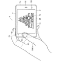
図10は操作領域30を触る指500の向きが0度である様子を示す図である。本例では、電子機器1を表示領域20側から見た場合において、操作領域30を触る指500(操作領域30上に置かれた指500)が指す方向が、表示領域20の長手方向に沿った方向であり、かつレシーバ穴22側に向かう方向(第1側面1c側に向かう方向)である場合、当該指500の向きを0度としている。言い換えれば、レシーバ穴22が上側に位置するように(第1側面1cが上側に位置するように)電子機器1を縦向きで表示領域20側から見た場合に、操作領域30を触る指500が時計の12時の方向を指している場合、当該指500の向きを0度としている。したがって、電子機器1が横向きで使用される場合であっても、図11に示されるように、操作領域30を触る指500が指す方向が、表示領域20の長手方向に沿った方向であり、かつレシーバ穴22側に向かう方向(第1側面1c側に向かう方向)である場合には、当該指500の向きは0度となる。つまり、電子機器1の姿勢(向き)にかかわらず、操作領域30を触る指500が指す方向が、表示領域20の長手方向に沿った方向であり、かつレシーバ穴22側に向かう方向である場合には、当該指500の向きは0度となる。   FIG. 10 is a diagram illustrating a state where the orientation of the finger 500 touching the operation area 30 is 0 degrees. In this example, when the electronic device 1 is viewed from the display area 20 side, the direction indicated by the finger 500 touching the operation area 30 (the finger 500 placed on the operation area 30) is along the longitudinal direction of the display area 20. And the direction toward the receiver hole 22 (the direction toward the first side face 1c) is 0 degree. In other words, when the electronic device 1 is viewed from the display area 20 side in the vertical direction so that the receiver hole 22 is located on the upper side (so that the first side surface 1c is located on the upper side), the finger 500 touches the operation area 30. Indicates the direction of 12:00 of the watch, the direction of the finger 500 is set to 0 degree. Therefore, even when the electronic device 1 is used in the horizontal direction, as shown in FIG. 11, the direction indicated by the finger 500 that touches the operation area 30 is a direction along the longitudinal direction of the display area 20. When the direction is toward the receiver hole 22 (the direction toward the first side surface 1c), the direction of the finger 500 is 0 degrees. That is, regardless of the posture (orientation) of the electronic device 1, the direction indicated by the finger 500 touching the operation region 30 is a direction along the longitudinal direction of the display region 20 and a direction toward the receiver hole 22 side. The direction of the finger 500 is 0 degree.

図12〜15は、それぞれ、操作領域30を触る指500の向きが+45度、+90度、−45度及び−90度である様子を示す図である。   12 to 15 are diagrams illustrating a state in which the orientation of the finger 500 touching the operation area 30 is +45 degrees, +90 degrees, −45 degrees, and −90 degrees, respectively.

図12に示されるように、電子機器1を表示領域20側から見た場合において、0度の向きの指500を、時計回りに45度回転させたときの当該指500の向きを+45度としている。言い換えれば、レシーバ穴22が上側にくるように電子機器1を縦向きで表示領域20側から見た場合に、操作領域30を触る指500が、時計の1時と2時の間の方向を指している場合の当該指500の向きを+45度としている。   As shown in FIG. 12, when the electronic device 1 is viewed from the display area 20 side, the direction of the finger 500 when the finger 500 oriented 0 degrees is rotated 45 degrees clockwise is set to +45 degrees. Yes. In other words, when the electronic device 1 is viewed vertically from the display area 20 side so that the receiver hole 22 is on the upper side, the finger 500 touching the operation area 30 points in the direction between 1 o'clock and 2 o'clock of the watch. The orientation of the finger 500 when it is present is +45 degrees.

図13に示されるように、電子機器1を表示領域20側から見た場合において、0度の向きの指500を、時計回りに90度回転させたときの当該指500の向きを+90度としている。言い換えれば、レシーバ穴22が上側にくるように電子機器1を縦向きで表示領域20側から見た場合に、操作領域30を触る指500が時計の3時の方向を指している場合の当該指500の向きを+90度としている。   As shown in FIG. 13, when the electronic device 1 is viewed from the display region 20 side, the direction of the finger 500 when the finger 500 oriented 0 degrees is rotated 90 degrees clockwise is set to +90 degrees. Yes. In other words, when the electronic device 1 is viewed from the display area 20 side with the receiver hole 22 facing upward, the finger 500 touching the operation area 30 points to the 3 o'clock direction of the watch. The direction of the finger 500 is +90 degrees.

図14に示されるように、電子機器1を表示領域20側から見た場合において、0度の向きの指500を、反時計回りに45度回転させたときの当該指500の向きを−45度としている。言い換えれば、レシーバ穴22が上側にくるように電子機器1を縦向きで表示領域20側から見た場合に、操作領域30を触る指500が、時計の10時と12時の間の方向を指している場合の当該指500の向きを−45度としている。   As shown in FIG. 14, when the electronic device 1 is viewed from the display region 20 side, the orientation of the finger 500 when the finger 500 oriented 0 degrees is rotated 45 degrees counterclockwise is −45. I am trying. In other words, when the electronic device 1 is viewed from the display area 20 side in the vertical direction so that the receiver hole 22 is on the upper side, the finger 500 touching the operation area 30 points in the direction between 10:00 and 12:00 on the watch. The orientation of the finger 500 when it is present is −45 degrees.

図15に示されるように、電子機器1を表示領域20側から見た場合において、0度の向きの指500を、反時計回りに90度回転させたときの当該指500の向きを−90度としている。言い換えれば、レシーバ穴22が上側にくるように電子機器1を縦向きで表示領域20側から見た場合に、操作領域30を触る指500が時計の9時の方向を指している場合の当該指500の向きを−90度としている。   As shown in FIG. 15, when the electronic device 1 is viewed from the display region 20 side, the orientation of the finger 500 when the finger 500 oriented 0 degrees is rotated 90 degrees counterclockwise is −90. I am trying. In other words, when the electronic device 1 is viewed from the display area 20 side in the vertical direction so that the receiver hole 22 is on the upper side, the finger 500 touching the operation area 30 points to the 9 o'clock direction of the watch. The direction of the finger 500 is set to −90 degrees.

図16〜20は、それぞれ、操作領域30を触る指の向きが0度、+45度、+90度、−45度及び−90度である場合の当該指の指紋の一例を模式的に示す図である。図16〜20に示される指紋は同じ指の指紋である。   16 to 20 are diagrams schematically illustrating an example of a fingerprint of the finger when the direction of the finger touching the operation region 30 is 0 degree, +45 degree, +90 degree, -45 degree, and -90 degree, respectively. is there. The fingerprints shown in FIGS. 16 to 20 are those of the same finger.

図16〜20に示されるように、指紋検出範囲141内の指紋は、同じ指であっても、指の向きによって異なる。したがって、同じ指であっても、指の向きに応じて、当該指の指紋から異なる特徴点が得られる。基準特徴点テーブル400には、操作領域30を触る正規ユーザの指500の向きが、0度、+45度、+90度、−45度及び−90度である場合のそれぞれにおいて、検出指紋の特徴を示す基準特徴点が登録されている。   As shown in FIGS. 16 to 20, the fingerprints in the fingerprint detection range 141 are different depending on the direction of the fingers even for the same finger. Therefore, even for the same finger, different feature points are obtained from the fingerprint of the finger according to the direction of the finger. In the reference feature point table 400, the characteristics of the detected fingerprint are shown when the orientation of the finger 500 of the authorized user who touches the operation area 30 is 0 degree, +45 degrees, +90 degrees, -45 degrees, and -90 degrees. The reference feature points shown are registered.

図21は、操作領域30に対する指の押圧の強さが大きい場合における指紋センサ140での検出指紋を模式的に示す図である。図22は、操作領域30に対する指の押圧の強さが普通の場合における指紋センサ140での検出指紋を模式的に示す図である。図23は、操作領域30に対する指の押圧の強さが小さい場合における指紋センサ140で検出指紋を模式的に示す図である。図21〜23は同じ指についての指紋が示されている。なお、図20〜22では、検出指紋の様子が理解しやすいように、指紋センサ140の指紋検出範囲141を仮想的に大きくしている。   FIG. 21 is a diagram schematically showing a detected fingerprint by the fingerprint sensor 140 when the strength of the finger pressing on the operation region 30 is large. FIG. 22 is a diagram schematically showing a detected fingerprint by the fingerprint sensor 140 in the case where the finger pressing force on the operation region 30 is normal. FIG. 23 is a diagram schematically illustrating a fingerprint detected by the fingerprint sensor 140 when the strength of the finger pressing on the operation region 30 is small. 21 to 23 show fingerprints for the same finger. 20 to 22, the fingerprint detection range 141 of the fingerprint sensor 140 is virtually enlarged so that the state of the detected fingerprint can be easily understood.

図21〜23に示されるように、同じ指であっても、操作領域30に対する指の押圧の強さに応じて検出指紋が変化する。具体的には、操作領域30に対する指の押圧の強さが大きいほど、当該指の指紋が操作領域30で押しつぶされて、指紋センサ140での検出指紋の稜線が太くなる。その結果、検出指紋の稜線の端点及び分岐点の位置が変化する。したがって、同じ指であっても、操作領域30に対する指の押圧の強さに応じて、当該指の指紋から異なる特徴点が得られる。基準特徴点テーブル400には、操作領域30に対する指の押圧の強さが「大きい」、「普通」及び「小さい」場合のそれぞれにおいて、検出指紋の特徴を示す基準特徴点が登録されている。   As shown in FIGS. 21 to 23, even for the same finger, the detected fingerprint changes according to the strength of the finger pressing on the operation region 30. Specifically, the greater the strength of the finger pressing on the operation area 30, the more the fingerprint of the finger is crushed in the operation area 30, and the ridgeline of the fingerprint detected by the fingerprint sensor 140 becomes thicker. As a result, the positions of the end points and branch points of the ridgeline of the detected fingerprint change. Therefore, even for the same finger, different feature points can be obtained from the fingerprint of the finger according to the strength of the finger pressing on the operation region 30. In the reference feature point table 400, reference feature points indicating the features of the detected fingerprint are registered in each of cases where the strength of the finger pressing on the operation area 30 is “large”, “normal”, and “small”.

制御部100は、指紋センサ140での指紋検出結果に基づいてユーザ認証を行う場合には、当該指紋検出結果から抽出した特徴点と、記憶部103に記憶されている複数の基準特徴点テーブル400に登録されている複数の基準特徴点とを比較する。   When the user authentication is performed based on the fingerprint detection result of the fingerprint sensor 140, the control unit 100 extracts the feature points extracted from the fingerprint detection result and a plurality of reference feature point tables 400 stored in the storage unit 103. A plurality of reference feature points registered in the are compared.

<基準特徴点の登録方法について>
指紋登録モードで動作する電子機器1では、表示領域20に対して所定の操作が行われると、表示領域20に指紋登録画面600が表示される。正規ユーザは、表示領域20に指紋登録画面600が表示されているとき、自身の指の指紋の特徴を示す基準特徴点を電子機器1に登録することができる。基準特徴点の登録は、電子機器1が図2に示されるような縦向きの状態で行われる。
<Registration method of reference feature points>
In the electronic device 1 operating in the fingerprint registration mode, when a predetermined operation is performed on the display area 20, a fingerprint registration screen 600 is displayed on the display area 20. When the fingerprint registration screen 600 is displayed in the display area 20, the authorized user can register the reference feature points indicating the characteristics of the fingerprint of his / her finger in the electronic device 1. The registration of the reference feature points is performed in a state where the electronic device 1 is in the vertical orientation as shown in FIG.

図24は指紋登録画面600の一例を示す図である。図24に示されるように、指紋登録画面600には、ユーザに対して操作領域30を触ることを指示する操作指示情報601が含まれる。また指紋登録画面600には、操作領域30を触る指の種類を指示する種類指示情報602と、操作領域30を触る指の向きを指示する向き指示情報603と、操作領域30を指で触る強さを指示する強さ指示情報604とが含まれている。正規ユーザは、種類指示情報602、向き指示情報603及び強さ指示情報604に従って操作領域30を指で触ることによって、種類指示情報602、向き指示情報603及び強さ指示情報604に応じた基準特徴点が基準特徴点テーブル400に登録される。図24の例では、操作領域30を触る指が右手親指、指の向きが0度、操作領域30に対する指の押圧の強さが小さい場合における検出指紋の特徴を示す基準特徴点(図9の基準特徴点α33に相当)が、右手親指に対応する基準特徴点テーブル400に登録される。図24の指紋登録画面600に含まれる「真上」は0度の向きを意味し、当該指紋登録画面600に含まれる「軽く触る」は操作領域30に対する指の押圧の強さが小さいことを意味する。   FIG. 24 is a view showing an example of a fingerprint registration screen 600. As shown in FIG. 24, the fingerprint registration screen 600 includes operation instruction information 601 for instructing the user to touch the operation area 30. The fingerprint registration screen 600 also includes type instruction information 602 for instructing the type of finger touching the operation area 30, direction instruction information 603 for instructing the direction of the finger touching the operation area 30, and the strength of touching the operation area 30 with a finger. And strength instruction information 604 for instructing the user. A regular user touches the operation area 30 with a finger according to the type instruction information 602, the direction instruction information 603, and the strength instruction information 604, so that the reference feature according to the type instruction information 602, the direction instruction information 603, and the strength instruction information 604 The point is registered in the reference feature point table 400. In the example of FIG. 24, the reference feature point indicating the feature of the detected fingerprint when the finger touching the operation region 30 is the right thumb, the finger orientation is 0 degree, and the finger pressing strength against the operation region 30 is small (in FIG. 9). (Corresponding to the reference feature point α33) is registered in the reference feature point table 400 corresponding to the right thumb. “Directly above” included in the fingerprint registration screen 600 of FIG. 24 means a direction of 0 degree, and “lightly touching” included in the fingerprint registration screen 600 indicates that the strength of the finger pressing on the operation area 30 is small. means.

一つの基準特徴点の登録が完了すると、表示領域20には登録完了画面610が表示される。図25は、図24に示される指紋登録画面600に対応する登録完了画面610の一例を示す図である。図25に示されるように、登録完了画面610には、種類指示情報602、向き指示情報603及び強さ指示情報604に加えて、指紋登録が完了したことをユーザに通知する完了通知情報605が含まれる。   When registration of one reference feature point is completed, a registration completion screen 610 is displayed in the display area 20. FIG. 25 is a diagram showing an example of a registration completion screen 610 corresponding to the fingerprint registration screen 600 shown in FIG. As shown in FIG. 25, in the registration completion screen 610, in addition to the type instruction information 602, the direction instruction information 603, and the strength instruction information 604, completion notification information 605 for notifying the user that the fingerprint registration is completed is included. included.

図26,27は指紋登録画面600の他の例を示す図である。図26の指紋登録画面600に含まれる「右上」は+45度の向きを意味し、当該指紋登録画面600に含まれる「少し押す」は操作領域30に対する指の押圧の強さが普通であることを意味する。また図27の指紋登録画面600に含まれる「左」は−90度の向きを意味し、当該指紋登録画面600に含まれる「強く押す」は操作領域30に対する指の押圧の強さが大きいことを意味する。ここでの「強く押す」とは、例えば、押しボタン150がオン状態にならない程度の強さである。   26 and 27 are diagrams showing another example of the fingerprint registration screen 600. FIG. “Upper right” included in the fingerprint registration screen 600 of FIG. 26 means a direction of +45 degrees, and “slightly pressed” included in the fingerprint registration screen 600 indicates that the strength of the finger pressing on the operation area 30 is normal. Means. Further, “left” included in the fingerprint registration screen 600 in FIG. 27 means a direction of −90 degrees, and “strongly pressed” included in the fingerprint registration screen 600 has a large finger pressing strength against the operation area 30. Means. Here, “strongly press” is, for example, a strength that does not cause the push button 150 to be turned on.

正規ユーザが、図26の指紋登録画面600に含まれる種類指示情報602、向き指示情報603及び強さ指示情報604に従って操作領域30を指で触ることによって、操作領域30を触る指が右手人差し指、指の向きが+45度、操作領域30に対する指の押圧の強さが普通である場合における検出指紋の特徴を示す基準特徴点が、右手人差し指に対応する基準特徴点テーブル400に登録される。   The authorized user touches the operation area 30 with his / her finger according to the type instruction information 602, the direction instruction information 603 and the strength instruction information 604 included in the fingerprint registration screen 600 of FIG. A reference feature point indicating the feature of the detected fingerprint when the finger orientation is +45 degrees and the finger pressing force on the operation region 30 is normal is registered in the reference feature point table 400 corresponding to the right index finger.

また正規ユーザが、図27の指紋登録画面600に含まれる種類指示情報602、向き指示情報603及び強さ指示情報604に従って操作領域30を指で触ることによって、操作領域30を触る指が左手中指、指の向きが−90度、操作領域30に対する指の押圧の強さが大きい場合における検出指紋の特徴を示す基準特徴点が、左手中指に対応する基準特徴点テーブル400に登録される。   In addition, when the authorized user touches the operation area 30 with a finger according to the type instruction information 602, the direction instruction information 603, and the strength instruction information 604 included in the fingerprint registration screen 600 of FIG. 27, the finger touching the operation area 30 The reference feature points indicating the features of the detected fingerprint when the finger orientation is -90 degrees and the finger pressing strength against the operation region 30 is large are registered in the reference feature point table 400 corresponding to the middle finger of the left hand.

ユーザは、表示領域20を操作することによって、表示領域20に表示される指紋登録画面600を変化させることができる。ユーザは、表示領域20に表示される指紋登録画面600を変化させながら、複数の基準特徴点を電子機器1に登録する。   The user can change the fingerprint registration screen 600 displayed on the display area 20 by operating the display area 20. The user registers a plurality of reference feature points in the electronic device 1 while changing the fingerprint registration screen 600 displayed in the display area 20.

<指の押圧の強さの判定について>
制御部100は、指紋センサ140での指紋検出結果を用いた所定の判定条件に基づいて、操作領域30に対する指の押圧の強さを判定することができる。制御部100は、操作領域30に対する指の押圧の強さを判定する際には、まず、指紋センサ140で得られる指紋画像から特徴点を抽出する。そして、制御部100は、記憶部103内の複数の基準特徴点において、抽出した特徴点と類似する基準特徴点を特定する。制御部100は、抽出した特徴点と類似する基準特徴点が登録されている基準特徴点テーブル400において、当該基準特徴点に対応付けられている指の押圧の強さを特定する。そして、制御部100は、特定した指の押圧の強さを、操作領域30に対する指の押圧の強さであると決定する。例えば、制御部100は、抽出した特徴点と類似する基準特徴点が登録されている基準特徴点テーブル400において、当該基準標準点に対応付けられている指の押圧の強さが「大きい」である場合には、操作領域30に対する指の押圧の強さが大きいと判定する。
<Determination of finger pressing strength>
The control unit 100 can determine the strength of the finger pressing on the operation region 30 based on a predetermined determination condition using the fingerprint detection result from the fingerprint sensor 140. When determining the strength of the finger pressing on the operation area 30, the control unit 100 first extracts feature points from the fingerprint image obtained by the fingerprint sensor 140. Then, the control unit 100 specifies a reference feature point similar to the extracted feature point among the plurality of reference feature points in the storage unit 103. In the reference feature point table 400 in which reference feature points similar to the extracted feature points are registered, the control unit 100 specifies the strength of the finger press associated with the reference feature points. Then, the control unit 100 determines that the specified finger pressing strength is the finger pressing strength with respect to the operation region 30. For example, in the reference feature point table 400 in which reference feature points similar to the extracted feature points are registered, the control unit 100 indicates that the strength of the finger press associated with the reference standard point is “high”. In some cases, it is determined that the strength of the finger pressing on the operation area 30 is large.

このように、制御部100は、操作領域30に対する指の押圧の強さを判定する強さ判定部として機能する。以後、特に断らない限り、「指の押圧の強さ」と言えば、操作領域30に対する指の押圧の強さを意味する。   As described above, the control unit 100 functions as a strength determination unit that determines the strength of the finger pressing on the operation region 30. Hereinafter, unless otherwise specified, “the strength of the finger pressing” means the strength of the finger pressing on the operation area 30.

<指の向きの判定について>
制御部100は、指紋センサ140での指紋検出結果を用いた所定の判定条件に基づいて、操作領域30を触る指の向きを判定することができる。制御部100は、操作領域30を触る指の向きを判定する際には、まず、指紋センサ140で得られる指紋画像から特徴点を抽出する。そして、制御部100は、記憶部103内の複数の基準特徴点において、抽出した特徴点と類似する基準特徴点を特定する。制御部100は、抽出した特徴点と類似する基準特徴点が登録されている基準特徴点テーブル400において、当該基準特徴点に対応付けられている指の向きを特定する。そして、制御部100は、特定した指の向きを、操作領域30を触る指の向きであると決定する。例えば、制御部100は、抽出した特徴点と類似する基準特徴点が登録されている基準特徴点テーブル400において、当該基準標準点に対応付けられている指の向きが「+90度」である場合には、操作領域30を触る指の向きが+90度であると判定する。
<Determination of finger orientation>
The control unit 100 can determine the orientation of the finger touching the operation region 30 based on a predetermined determination condition using the fingerprint detection result from the fingerprint sensor 140. When determining the orientation of the finger touching the operation area 30, the control unit 100 first extracts feature points from the fingerprint image obtained by the fingerprint sensor 140. Then, the control unit 100 specifies a reference feature point similar to the extracted feature point among the plurality of reference feature points in the storage unit 103. The control unit 100 specifies the orientation of the finger associated with the reference feature point in the reference feature point table 400 in which reference feature points similar to the extracted feature points are registered. Then, the control unit 100 determines that the identified finger orientation is the orientation of the finger touching the operation area 30. For example, in the reference feature point table 400 in which reference feature points similar to the extracted feature points are registered, the control unit 100 has a finger orientation “+90 degrees” associated with the reference standard point. It is determined that the direction of the finger touching the operation area 30 is +90 degrees.

このように、制御部100は、操作領域30を触る指の向きを判定する向き判定部として機能する。以後、特に断らない限り、「指の向き」と言えば、操作領域30を触る指の向きを意味する。   As described above, the control unit 100 functions as a direction determination unit that determines the direction of the finger touching the operation region 30. Hereinafter, unless otherwise specified, “finger orientation” means the orientation of the finger touching the operation area 30.

<指の種類の判定について>
制御部100は、指紋センサ140での指紋検出結果を用いた所定の判定条件に基づいて、操作領域30を触る指の種類を判定することができる。制御部100は、操作領域30を触る指の種類を判定する際には、まず、指紋センサ140で得られる指紋画像から特徴点を抽出する。そして、制御部100は、記憶部103内の複数の基準特徴点において、抽出した特徴点と類似する基準特徴点を特定する。制御部100は、抽出した特徴点と類似する基準特徴点が登録されている基準特徴点テーブル400が対応する指の種類を、操作領域30を触る指の種類であると決定する。例えば、制御部100は、抽出した特徴点と類似する基準特徴点が登録されている基準特徴点テーブル400が右手親指に対応する場合、操作領域30を触る指の種類が右手親指であると決定する。
<Determination of finger type>
The control unit 100 can determine the type of finger touching the operation area 30 based on a predetermined determination condition using the fingerprint detection result of the fingerprint sensor 140. When determining the type of finger touching the operation area 30, the control unit 100 first extracts feature points from the fingerprint image obtained by the fingerprint sensor 140. Then, the control unit 100 specifies a reference feature point similar to the extracted feature point among the plurality of reference feature points in the storage unit 103. The control unit 100 determines that the finger type corresponding to the reference feature point table 400 in which reference feature points similar to the extracted feature points are registered is the finger type that touches the operation area 30. For example, when the reference feature point table 400 in which reference feature points similar to the extracted feature points are registered corresponds to the right thumb, the control unit 100 determines that the type of finger touching the operation area 30 is the right thumb. To do.

このように、制御部100は、操作領域30を触る指の種類を判定する種類判定部として機能する。以後、特に断らない限り、「指の種類」と言えば、操作領域30を触る指の種類を意味する。   In this way, the control unit 100 functions as a type determination unit that determines the type of finger that touches the operation region 30. Hereinafter, unless otherwise specified, “finger type” means the type of finger touching the operation area 30.

<指の押圧の強さ、指の向き及び指の種類に応じた処理について>
制御部100は、指の押圧の強さに応じて、実行する処理を変化させることができる。また制御部100は、指の向きに応じて、実行する処理を変化させることができる。そして制御部100は、指の種類に応じて、実行する処理を変化させることができる。以下に、スリープモードから通常モードに復帰する際の電子機器1の動作を例に挙げて、この点を説明する。
<Regarding the processing according to the strength of finger pressing, finger orientation, and finger type>
The control part 100 can change the process to perform according to the strength of a finger press. Moreover, the control part 100 can change the process to perform according to direction of a finger | toe. And the control part 100 can change the process to perform according to the kind of finger | toe. Hereinafter, this point will be described by taking the operation of the electronic device 1 when returning from the sleep mode to the normal mode as an example.

図28はスリープモードから通常モードに復帰する際の電子機器1の動作の一例を示すフローチャートである。スリープモードで動作する電子機器1の操作領域30が押されて押しボタン150がオン状態になると、ステップs1において、電子機器1の動作モードはスリープモードから通常モードに復帰する。そして、ステップs2において、表示領域20にロック画面が表示される。   FIG. 28 is a flowchart showing an example of the operation of the electronic device 1 when returning from the sleep mode to the normal mode. When the operation area 30 of the electronic device 1 operating in the sleep mode is pressed and the push button 150 is turned on, the operation mode of the electronic device 1 returns from the sleep mode to the normal mode in step s1. In step s2, a lock screen is displayed in the display area 20.

ステップs2の後、制御部100は、動作が停止している指紋センサ140を動作させて、指紋センサ140の出力信号を監視する。ステップs3において、指紋センサ140がユーザの指の指紋を検出すると、ステップs4において、制御部100は、指紋センサ140での指紋検出結果に基づいてユーザ認証を開始する。そして、制御部100は、指紋センサ140の出力信号の監視を停止する。   After step s2, the control unit 100 operates the fingerprint sensor 140 whose operation is stopped, and monitors the output signal of the fingerprint sensor 140. In step s3, when the fingerprint sensor 140 detects the fingerprint of the user's finger, in step s4, the control unit 100 starts user authentication based on the fingerprint detection result by the fingerprint sensor 140. Then, the control unit 100 stops monitoring the output signal of the fingerprint sensor 140.

ユーザ認証が終了すると、ステップs5において、制御部100は、ユーザ認証に成功したか否かを判定する。ユーザ認証に成功したと判定されると、制御部100はステップs6を実行する。一方で、ユーザ認証に失敗したと判定されると、制御部100は、指紋センサ140の出力信号を再度監視する。その後、ステップs3が実行されて指紋センサ140がユーザの指の指紋を検出すると、以後、電子機器1は同様に動作する。   When the user authentication ends, in step s5, the control unit 100 determines whether the user authentication is successful. If it is determined that the user authentication is successful, the control unit 100 executes Step s6. On the other hand, if it is determined that the user authentication has failed, the control unit 100 monitors the output signal of the fingerprint sensor 140 again. Thereafter, when step s3 is executed and the fingerprint sensor 140 detects the fingerprint of the user's finger, the electronic device 1 thereafter operates in the same manner.

ステップs6では、制御部100は、ステップs3で得られた指紋検出結果に基づいて、指の押圧の強さが大きいか否かを判定する。ステップs6では、制御部100は、上述のようにして、ステップs3で得られた指紋検出結果を用いた所定の判定条件に基づいて、指の押圧の強さを判定する。制御部100は、指の押圧の強さが大きいと判定した場合、ステップs7を実行する。一方で、制御部100は、指の押圧の強さが大きくないと判定した場合、つまり指の押圧の強さが普通であると判定した場合と小さいと判定した場合には、ステップs13において、表示パネル120にホーム画面を表示させる。これにより、表示領域20の表示がロック画面からホーム画面に遷移する。   In step s6, the control unit 100 determines whether or not the finger pressing strength is large based on the fingerprint detection result obtained in step s3. In step s6, as described above, the control unit 100 determines the strength of the finger press based on a predetermined determination condition using the fingerprint detection result obtained in step s3. When the control unit 100 determines that the strength of the finger pressing is large, the control unit 100 executes Step s7. On the other hand, if the control unit 100 determines that the finger pressing strength is not large, that is, if it is determined that the finger pressing strength is normal or small, in step s13, A home screen is displayed on the display panel 120. Thereby, the display of the display area 20 changes from the lock screen to the home screen.

このように、ユーザは、ロック画面を表示する電子機器1の操作領域30を指で軽く触れることによって、あるいは操作領域30を指で少し押すことによって、電子機器1の表示をロック画面からホーム画面に変化させることができる。   In this way, the user touches the operation area 30 of the electronic device 1 that displays the lock screen with a finger or presses the operation area 30 with a finger slightly to change the display of the electronic device 1 from the lock screen to the home screen. Can be changed.

ステップs7では、制御部100は、ステップs3で得られた指紋検出結果に基づいて、指の種類が親指であるか否かを判定する。ステップs7では、制御部100は、上述のようにして、ステップs3で得られた指紋検出結果を用いた所定の判定条件に基づいて、指の種類を判定する。制御部100は、指の種類が親指であると判定すると、ステップs8を実行する。つまり、制御部100は、指の種類が右手親指であると判定した場合と、左手親指であると判定した場合には、ステップs8を実行する。一方で、制御部100は、指の種類が親指ではないと判定すると、ステップs11において、指の種類が人差し指であるか否かを判定する。   In step s7, the control unit 100 determines whether or not the finger type is the thumb based on the fingerprint detection result obtained in step s3. In step s7, the control unit 100 determines the finger type based on a predetermined determination condition using the fingerprint detection result obtained in step s3 as described above. When determining that the finger type is the thumb, the control unit 100 executes Step s8. That is, the control unit 100 executes step s8 when it is determined that the finger type is the right thumb and when the finger type is the left thumb. On the other hand, when determining that the finger type is not the thumb, the control unit 100 determines whether or not the finger type is the index finger in step s11.

ステップs11において、制御部100は、指の種類が人差し指であると判定した場合、ステップs12において、記憶部103内のウェブブラウザを実行する。つまり、制御部100は、指の種類が右手人差し指であると判定した場合と、左手人差し指であると判定した場合には、ウェブブラウザを実行する。ウェブブラウザの実行中の制御部100は、ウェブサーバから無線通信部110を通じてウェブページを取得し、取得したウェブページを表示パネル120に表示させる。これにより、表示領域20の表示が、ロック画面からウェブページに遷移する。   In step s11, when the control unit 100 determines that the type of the finger is an index finger, the control unit 100 executes the web browser in the storage unit 103 in step s12. That is, the control unit 100 executes the web browser when it is determined that the finger type is the right hand index finger and when the finger type is the left hand index finger. The control unit 100 executing the web browser acquires a web page from the web server through the wireless communication unit 110 and causes the display panel 120 to display the acquired web page. Thereby, the display of the display area 20 changes from the lock screen to the web page.

一方で、ステップs11において、制御部100は、指の種類が人差し指でないと判定すると、ステップs13を実行して、表示パネル120にホーム画面を表示させる。これにより、表示領域20の表示が、ロック画面からホーム画面に遷移する。   On the other hand, when determining in step s11 that the finger type is not the index finger, the control unit 100 executes step s13 to display the home screen on the display panel 120. Thereby, the display of the display area 20 changes from the lock screen to the home screen.

このように、ユーザは、ロック画面を表示する電子機器1の操作領域30を人差し指で強く押すことによって、電子機器1のウェブブラウザを実行させることができ、電子機器1の表示をロック画面からウェブページに変化させることができる。またユーザは、ロック画面を表示する電子機器1の操作領域30を親指及び人差し指以外の指で強く押すことによって、電子機器1の表示をロック画面からホーム画面に変化させることができる。   As described above, the user can cause the web browser of the electronic device 1 to be executed by strongly pressing the operation area 30 of the electronic device 1 that displays the lock screen with an index finger. Can be changed to a page. The user can change the display of the electronic device 1 from the lock screen to the home screen by strongly pressing the operation area 30 of the electronic device 1 that displays the lock screen with a finger other than the thumb and the index finger.

ステップs7において指の種類が親指であると判定されると、ステップs8において、制御部100は、上述のようにして、ステップs3で得られた指紋検出結果を用いた所定の判定条件に基づいて、指の向きを判定する。そして、制御部100は、ステップs9において、指の向きに応じて、表示領域20の表示(表示パネル120の表示)の向きを決定する。ステップs9での処理については後で詳細に説明する。   If it is determined in step s7 that the finger type is the thumb, in step s8, the control unit 100 performs the determination based on the predetermined determination condition using the fingerprint detection result obtained in step s3 as described above. , Determine the direction of the finger. In step s9, the control unit 100 determines the display direction of the display area 20 (display of the display panel 120) according to the direction of the finger. The process in step s9 will be described in detail later.

ステップs9の後、ステップs10において、制御部100は記憶部103内のカメラアプリケーションを実行する。カメラプリケーションの実行が開始されると、制御部100は、前面側撮像部190及び裏面側撮像部200のどちらか一方を起動する。そして、制御部100は、起動させた撮像部での撮像画像を表示パネル120に表示させる。このとき、制御部100は、表示パネル120を制御して、表示領域20の表示の向き(表示パネル120の表示の向き)を、ステップs9で決定した向きに設定する。カメラアプリケーションの実行中では、表示領域20にシャッタボタンが表示される。   After step s9, in step s10, the control unit 100 executes the camera application in the storage unit 103. When the execution of the camera application is started, the control unit 100 activates either the front side imaging unit 190 or the back side imaging unit 200. Then, the control unit 100 causes the display panel 120 to display a captured image of the activated imaging unit. At this time, the control unit 100 controls the display panel 120 to set the display direction of the display area 20 (the display direction of the display panel 120) to the direction determined in step s9. While the camera application is being executed, a shutter button is displayed in the display area 20.

このように、ユーザは、ロック画面を表示する電子機器1の操作領域30を親指で強く押すことによって、電子機器1にカメラアプリケーションを実行させることができ、電子機器1の表示をロック画面から撮像部での撮像画像に変化させることができる。   In this way, the user can cause the electronic device 1 to execute the camera application by strongly pressing the operation area 30 of the electronic device 1 that displays the lock screen with the thumb, and can capture the display of the electronic device 1 from the lock screen. The image can be changed to a captured image at the section.

<ステップs9の詳細について>
ステップs9において、制御部100は、指の向きが0度のときには、上述の図10に示されるように、ユーザは第1側面1cを上側にした縦向きで電子機器1を使用していると判定する。そして、制御部100は、電子機器1の向きに応じて表示領域20の表示を縦向きに決定する。つまり、制御部100は、表示領域20の表示の向きを、第1側面1cを上側にした縦向きの電子機器1の表示領域20を見た際に、表示領域20に表示される文字及び図形等の情報が正しい姿勢(本来の姿勢)で視認できるような向きに決定する。これにより、ステップs10の後にカメラアプリケーションを実行している電子機器1では、表示領域20の表示の向きは、図29,30に示されるような向きとなる。制御部100は、指の向きが0度のときには、指の種類が右手親指であるか左手親指であるかにかかわらず、表示領域20の表示を縦向きに決定する。図29には、ユーザが右手親指500rtで縦向きの電子機器1の操作領域30を触る様子が示されている。図30には、ユーザが左手親指500ltで縦向きの電子機器1の操作領域30を触る様子が示されている。図29に示される右手親指500rtの向き及び図30に示される左手親指500ltの向きはともに0度である。
<Details of Step s9>
In step s9, when the orientation of the finger is 0 degree, the control unit 100 indicates that the user is using the electronic device 1 in the vertical orientation with the first side surface 1c facing upward, as shown in FIG. 10 described above. judge. Then, the control unit 100 determines the display of the display area 20 in the vertical orientation according to the orientation of the electronic device 1. That is, the control unit 100 displays characters and graphics displayed in the display area 20 when viewing the display area 20 of the vertically oriented electronic device 1 with the first side surface 1c facing upward. Is determined so that the information can be visually recognized in a correct posture (original posture). Thereby, in the electronic device 1 which is executing the camera application after step s10, the display direction of the display area 20 is as shown in FIGS. When the direction of the finger is 0 degree, the control unit 100 determines the display of the display area 20 in the vertical direction regardless of whether the finger type is the right thumb or the left thumb. FIG. 29 shows a state in which the user touches the operation area 30 of the vertical electronic device 1 with the right thumb 500rt. FIG. 30 shows a state in which the user touches the operation area 30 of the vertical electronic device 1 with the left thumb 500lt. The orientation of the right thumb 500rt shown in FIG. 29 and the orientation of the left thumb 500lt shown in FIG. 30 are both 0 degrees.

ステップs9において、制御部100は、指の種類が右手親指であって、指の向きが+90度のときには、ユーザは第3側面1eを上側にした横向きで電子機器1を使用していると判定する。そして、制御部100は、電子機器1の向きに応じて表示領域20の表示を横向きに決定する。つまり、制御部100は、表示領域20の表示の向きを、第3側面1eを上側にした横向きの電子機器1の表示領域20を見た際に、表示領域20に表示される文字、図形及び画像等の情報が正しい姿勢(本来の姿勢)で視認できるような向きに決定する。これにより、ステップs10の後にカメラアプリケーションを実行している電子機器1では、表示領域20の表示の向きは図31に示されるような向きとなる。図31には、ユーザが第3側面1eを上側にした横向きの電子機器1の操作領域30を右手親指500rtで触る様子が示されている。図31に示される右手親指500rtの向きは+90度である。   In step s9, when the finger type is the right thumb and the finger orientation is +90 degrees, the control unit 100 determines that the user is using the electronic device 1 with the third side face 1e facing upward. To do. Then, the control unit 100 determines the display of the display area 20 in the landscape orientation according to the orientation of the electronic device 1. That is, when the control unit 100 looks at the display area 20 of the horizontal electronic device 1 with the third side surface 1e on the display direction of the display area 20, the characters, graphics, and The orientation is determined such that information such as an image can be viewed with a correct posture (original posture). As a result, in the electronic device 1 that is executing the camera application after step s10, the display direction of the display area 20 is as shown in FIG. FIG. 31 shows a state in which the user touches the operation area 30 of the lateral electronic device 1 with the third side face 1e facing upward with the right thumb 500rt. The direction of the right thumb 500rt shown in FIG. 31 is +90 degrees.

ステップs9において、制御部100は、指の種類が左手親指であって、指の向きが−90度のときには、ユーザは第4側面1fを上側にした横向きで電子機器1を使用していると判定する。そして、制御部100は、電子機器1の向きに応じて表示領域20の表示を横向きに決定する。つまり、制御部100は、表示領域20の表示の向きを、第4側面1fを上側にした横向きの電子機器1の表示領域20を見た際に、表示領域20に表示される文字及び図形等の情報が正しい姿勢(本来の姿勢)で視認できるような向きに決定する。これにより、ステップs10の後にカメラアプリケーションを実行している電子機器1では、表示領域20の表示の向きは図32に示されるような向きとなる。図32には、ユーザが第4側面1fを上側にした横向きの電子機器1の操作領域30を左手親指500ltで触る様子が示されている。図32に示される左手親指500ltの向きは−90度である。   In step s9, when the finger type is the left thumb and the finger orientation is -90 degrees, the control unit 100 determines that the user is using the electronic device 1 in a landscape orientation with the fourth side surface 1f facing upward. judge. Then, the control unit 100 determines the display of the display area 20 in the landscape orientation according to the orientation of the electronic device 1. That is, when the control unit 100 looks at the display area 20 of the horizontal electronic device 1 with the fourth side surface 1f facing upward as the display direction of the display area 20, characters, graphics, and the like displayed on the display area 20 The orientation is determined so that the information can be visually recognized with the correct posture (original posture). Thereby, in the electronic device 1 which is executing the camera application after step s10, the display direction of the display area 20 is as shown in FIG. FIG. 32 shows a state in which the user touches the operation area 30 of the lateral electronic device 1 with the fourth side surface 1f facing upward with the left thumb 500lt. The orientation of the left thumb 500lt shown in FIG. 32 is −90 degrees.

このように、制御部100が、指紋検出範囲141を触る指の向きに応じて表示領域20の表示を決定することによって、電子機器1は、当該電子機器1の向きに応じて表示領域20の表示の向きを変えることが可能となる。よって、電子機器1は、ユーザにとって見やすい表示を自動的に行うことが可能となる。   As described above, the control unit 100 determines the display of the display area 20 according to the orientation of the finger touching the fingerprint detection range 141, so that the electronic device 1 can display the display area 20 according to the orientation of the electronic device 1. The display orientation can be changed. Therefore, the electronic device 1 can automatically perform display that is easy for the user to see.

以上のように、図28の例では、制御部100は、指の押圧の強さが大きいときにはウェブブラウザ等のアプリケーションを実行し、指の押圧の強さが大きくないときには表示パネル120にホーム画面を表示させる。   As described above, in the example of FIG. 28, the control unit 100 executes an application such as a web browser when the finger pressing strength is high, and displays the home screen on the display panel 120 when the finger pressing strength is not high. Is displayed.

また図28の例では、制御部100は、指の種類が親指のときにはカメラアプリケーションを実行し、指の種類が人差し指のときにはウェブブラウザを実行し、指の種類が親指及び人差し指以外のときには表示パネル120にホーム画面を表示させる。   In the example of FIG. 28, the control unit 100 executes the camera application when the finger type is the thumb, executes the web browser when the finger type is the index finger, and displays the display panel when the finger type is other than the thumb and the index finger. The home screen is displayed at 120.

そして図28の例では、制御部100は、指の向きが0度のときには表示領域20の表示の向きを縦向きに設定し、指の向きが+90度のとき及び−90度のときには表示領域20の表示の向きを横向きに設定する。   In the example of FIG. 28, the control unit 100 sets the display direction of the display area 20 to vertical when the finger orientation is 0 degrees, and displays when the finger orientation is +90 degrees and −90 degrees. The display direction of 20 is set to landscape.

なお、ユーザが右手親指で縦向きの電子機器1の操作領域30を触る場合には、図33に示されるように、右手親指500rtの向きが−45度になることがある。したがって、ステップs9においては、指の種類が右手親指であって、指の向きが−45度のときには、表示領域20の表示が縦向きに決定されても良い。   When the user touches the operation area 30 of the vertical electronic device 1 with the right thumb, as shown in FIG. 33, the direction of the right thumb 500rt may be −45 degrees. Therefore, in step s9, when the finger type is the right thumb and the finger orientation is −45 degrees, the display of the display area 20 may be determined to be in the portrait orientation.

また、ユーザが左手親指で縦向きの電子機器1の操作領域30を触る場合には、図34に示されるように、左手親指500ltの向きが+45度になることがある。したがって、ステップs9においては、指の種類が左手親指であって、指の向きが+45度のときには、表示領域20の表示が縦向きに決定されても良い。   In addition, when the user touches the operation area 30 of the vertical electronic device 1 with the left thumb, as shown in FIG. 34, the orientation of the left thumb 500lt may be +45 degrees. Therefore, in step s9, when the finger type is the left thumb and the finger orientation is +45 degrees, the display of the display area 20 may be determined to be in the vertical orientation.

また、ユーザが右手親指で横向きの電子機器1の操作領域30を触る場合には、図35に示されるように、右手親指500rtの向きが+45度になることがある。したがって、ステップs9においては、指の種類が右手親指であって、指の向きが+45度のときには、表示領域20の表示が横向きに決定されても良い。   In addition, when the user touches the operation area 30 of the electronic device 1 in the horizontal direction with the thumb of the right hand, the orientation of the right thumb 500rt may be +45 degrees as shown in FIG. Therefore, in step s9, when the finger type is the right thumb and the finger orientation is +45 degrees, the display of the display area 20 may be determined to be landscape.

また、ユーザが左手親指で横向きの電子機器1の操作領域30を触る場合には、図36に示されるように、左手親指500ltの向きが−45度になることがある。したがって、ステップs9においては、指の種類が左手親指であって、指の向きが−45度のときには、表示領域20の表示が横向きに決定されても良い。   When the user touches the operation area 30 of the electronic device 1 with the left thumb, the orientation of the left thumb 500lt may be −45 degrees as shown in FIG. Therefore, in step s9, when the finger type is the left thumb and the finger orientation is −45 degrees, the display of the display area 20 may be determined to be in landscape orientation.

図28の例では、ステップs11とステップs12の間に、ステップs8及びステップs9と同様の処理が実行されて、指の向きに応じて表示領域20の表示の向きが決定されても良い。この場合には、ステップs12の後のウェブブラウザを実行している電子機器1では、表示領域20に表示されるウェブページの向きが、ステップs11とステップs12の間で決定された向きとなる。   In the example of FIG. 28, processing similar to that in steps s8 and s9 may be executed between steps s11 and s12, and the display orientation of the display area 20 may be determined according to the orientation of the finger. In this case, in the electronic device 1 executing the web browser after step s12, the orientation of the web page displayed in the display area 20 is the orientation determined between step s11 and step s12.

また図28の例では、ステップs13の直前に、ステップs8及びステップs9と同様の処理が実行されて、指の向きに応じて表示領域20の表示の向きが決定されても良い。この場合には、ステップs13で表示されるホーム画面の向きが、ステップs13の直前に決定された向きとなる。   In the example of FIG. 28, immediately before step s13, the same processing as in steps s8 and s9 may be executed, and the display orientation of the display area 20 may be determined according to the orientation of the finger. In this case, the orientation of the home screen displayed in step s13 is the orientation determined immediately before step s13.

また図28の例では、ステップs7において指の種類が親指であると判定された場合には、カメラアプリケーション以外のアプリケーションが実行されても良い。例えば、メールアプリケーション、音楽再生制御アプリケーションあるいはユーザによって指定されたアプリケーションが実行されても良い。また、ウェブブラウザが実行されても良い。この場合には、指の種類が親指である場合であっても、人差し指である場合であっても、ウェブブラウザが実行される。   In the example of FIG. 28, if it is determined in step s7 that the finger type is the thumb, an application other than the camera application may be executed. For example, a mail application, a music playback control application, or an application designated by the user may be executed. A web browser may be executed. In this case, the web browser is executed regardless of whether the finger type is the thumb or the index finger.

また図28の例では、ステップs11において指の種類が人差し指であると判定された場合には、ウェブブラウザ以外のアプリケーションが実行されても良い。例えば、メールアプリケーション、音楽再生制御アプリケーションあるいはユーザによって指定されたアプリケーションが実行されても良い。また、カメラアプリケーションが実行されても良い。この場合には、指の種類が親指である場合であっても、人差し指である場合であっても、カメラアプリケーションが実行される。   In the example of FIG. 28, if it is determined in step s11 that the finger type is the index finger, an application other than the web browser may be executed. For example, a mail application, a music playback control application, or an application designated by the user may be executed. Further, a camera application may be executed. In this case, the camera application is executed regardless of whether the finger type is the thumb or the index finger.

また図28の例では、ステップs7において指の種類が親指であるか否かが判定されたが、親指以外の指であるか否かが判定されても良い。例えば、ステップs7において、指の種類が中指であるか否かが判定されても良い。また、ステップs11において指の種類が人差し指であるか否かが判定されたが、人差し指以外の指であるか否かが判定されても良い。例えば、ステップs11において、指の種類が小指であるか否かが判定されても良い。   In the example of FIG. 28, it is determined whether or not the finger type is the thumb in step s7, but it may be determined whether or not the finger is a finger other than the thumb. For example, in step s7, it may be determined whether or not the finger type is a middle finger. In step s11, it is determined whether or not the finger type is the index finger. However, it may be determined whether or not the finger is a finger other than the index finger. For example, in step s11, it may be determined whether or not the finger type is a little finger.

上記の例では、正規ユーザの右手の指についての基準特徴点と、正規ユーザの左手の指についての基準特徴点とが電子機器1に登録されていたが、正規ユーザは、右手及び左手のどちらか一方だけの指についての基準特徴点を電子機器1に登録しても良い。例えば、正規ユーザは、自分の利き手だけの指についての基準特徴点を電子機器1に登録しても良い。   In the above example, the reference feature point for the finger of the right user's right hand and the reference feature point for the finger of the right user's left hand are registered in the electronic device 1. Reference feature points for only one of the fingers may be registered in the electronic device 1. For example, the authorized user may register the reference feature point for the finger of only his / her dominant hand in the electronic device 1.

また上記の例では、正規ユーザの10本の指のすべてについての基準特徴点が電子機器1に登録されていたが、正規ユーザは、10本の指のうちの一部の指だけについての基準特徴点を電子機器1に登録しても良い。   In the above example, the reference feature points for all of the ten fingers of the authorized user are registered in the electronic device 1. However, the authorized user may use the criteria for only some of the ten fingers. The feature points may be registered in the electronic device 1.

また、制御部100は、指の種類を判定しているが、指の種類を判定しなくても良い。この場合には、図28の例では、ステップs6でYesと判定されるとステップs8が実行され、ステップs7,s11,s12は実行されない。   Moreover, although the control part 100 determines the kind of finger, it does not need to determine the kind of finger. In this case, in the example of FIG. 28, when it is determined Yes in step s6, step s8 is executed, and steps s7, s11, and s12 are not executed.

また、制御部100は、指の向きを判定しなくても良い。この場合には、図28の例では、ステップs7でYesと判定されるとステップs10が実行され、ステップs8,s9が実行されない。   Further, the control unit 100 may not determine the direction of the finger. In this case, in the example of FIG. 28, if it is determined Yes in step s7, step s10 is executed, and steps s8 and s9 are not executed.

また、制御部100は、指の押圧の強さを判定しなくても良い。この場合には、図28の例では、ステップs5でYesと判定されるとステップs7が実行され、ステップs6が実行されない。   Moreover, the control part 100 does not need to determine the strength of a finger press. In this case, in the example of FIG. 28, if it is determined Yes in step s5, step s7 is executed, and step s6 is not executed.

また、制御部100は、指の種類の判定と指の向きの判定を行わなくても良い。この場合には、図28の例では、ステップs6でYesと判定されるとステップs10が実行され、ステップs7〜s9,s11,s12が実行されない。   Further, the control unit 100 does not have to determine the finger type and the finger orientation. In this case, in the example of FIG. 28, if it is determined Yes in step s6, step s10 is executed, and steps s7 to s9, s11, and s12 are not executed.

また、制御部100は、指の種類の判定と指の押圧の強さの判定を行わなくても良い。この場合には、図28の例では、ステップs5でYesと判定されるとステップs8が実行され、ステップs6,s7,s11〜s13が実行されない。この場合には、ステップs10では、カメラアプリケーションの実行の代わりにホーム画面が表示されても良い。   Moreover, the control part 100 does not need to perform the determination of the kind of finger and the determination of the strength of the finger pressing. In this case, in the example of FIG. 28, if it is determined Yes in step s5, step s8 is executed, and steps s6, s7, s11 to s13 are not executed. In this case, in step s10, a home screen may be displayed instead of executing the camera application.

また、制御部100は、指の向きと指の押圧の強さの判定を行わなくても良い。この場合には、図28の例では、ステップs5でYesと判定されるとステップs7が実行され、ステップs7でYesと判定されるとステップs10が実行され、ステップs6,s8,s9が実行されない。   Moreover, the control part 100 does not need to determine the direction of the finger and the strength of pressing the finger. In this case, in the example of FIG. 28, if it is determined Yes in step s5, step s7 is executed, and if it is determined Yes in step s7, step s10 is executed, and steps s6, s8, and s9 are not executed. .

以上のように、電子機器1では、制御部100は、指紋センサ140の指紋検出範囲141に対する指の押圧の強さに応じて、実行する処理を変化させる。したがって、ユーザは、指紋センサ140の指紋検出範囲141を指で押す力(触る力)を変化させることによって、電子機器1に異なる処理を実行させることができる。よって、ユーザは電子機器1に対する簡単な操作で、所望の処理を電子機器1に実行させることができる。その結果、電子機器1の操作性が向上する。   As described above, in the electronic device 1, the control unit 100 changes the process to be executed according to the strength of the finger pressing on the fingerprint detection range 141 of the fingerprint sensor 140. Therefore, the user can cause the electronic device 1 to execute different processes by changing the force (touching force) for pressing the fingerprint detection range 141 of the fingerprint sensor 140 with a finger. Therefore, the user can cause the electronic device 1 to execute a desired process with a simple operation on the electronic device 1. As a result, the operability of the electronic device 1 is improved.

また、制御部100は、指紋センサ140の指紋検出範囲141を触る指についての電子機器1に対する相対的な向きに応じて、実行する処理を変化させる。したがって、ユーザは、指紋センサ140の指紋検出範囲141を触る指の向きを変化させることによって、電子機器1に異なる処理を実行させることができる。よって、ユーザは電子機器1に対する簡単な操作で、所望の処理を電子機器1に実行させることができる。その結果、電子機器1の操作性が向上する。   In addition, the control unit 100 changes the process to be executed according to the relative orientation of the finger touching the fingerprint detection range 141 of the fingerprint sensor 140 with respect to the electronic device 1. Therefore, the user can cause the electronic device 1 to execute different processes by changing the direction of the finger touching the fingerprint detection range 141 of the fingerprint sensor 140. Therefore, the user can cause the electronic device 1 to execute a desired process with a simple operation on the electronic device 1. As a result, the operability of the electronic device 1 is improved.

また、制御部100は、指紋センサ140の指紋検出範囲141を触る指の種類に応じて、実行する処理を変化させる。したがって、ユーザは、指紋センサ140の指紋検出範囲141を触る指の種類を変えることによって、電子機器1に異なる処理を実行させることができる。よって、ユーザは電子機器1に対する簡単な操作で、所望の処理を電子機器1に実行させることができる。その結果、電子機器1の操作性が向上する。   In addition, the control unit 100 changes processing to be executed according to the type of finger touching the fingerprint detection range 141 of the fingerprint sensor 140. Therefore, the user can cause the electronic device 1 to execute different processes by changing the type of finger touching the fingerprint detection range 141 of the fingerprint sensor 140. Therefore, the user can cause the electronic device 1 to execute a desired process with a simple operation on the electronic device 1. As a result, the operability of the electronic device 1 is improved.

なお上記の例では、制御部100は、指紋センサ140で検出された指紋についての特徴点と、指の押圧の強さに応じた複数の基準特徴点とを比較することによって、指の押圧の強さを判定しているが、指紋センサ140で検出された指紋の稜線の太さに基づいて、指の押圧の強さを判定しても良い。例えば、記憶部103に、指の押圧の強さが普通の場合の当該指の指紋の稜線の太さを基準太さとして登録する。そして、制御部100は、指紋センサ140で検出された指紋の稜線の太さと、記憶部103内の基準太さとを比較し、その比較結果に基づいて、指の押圧の強さを判定する。例えば、制御部100は、指紋センサ140で検出された指紋の稜線の太さと基準太さとの差の絶対値がしきい値以下であれば、指の押圧の強さが普通であると判定する。また制御部100は、指紋センサ140で検出された指紋の稜線の太さから基準太さを差し引いた値がプラスであって、その値の絶対値がしきい値よりも大きい場合には、指の押圧の強さが大きいと判定する。そして、制御部100は、指紋センサ140で検出された指紋の稜線の太さから基準太さを差し引いた値がマイナスであって、その値の絶対値がしきい値よりも大きい場合には、指の押圧の強さが小さいと判定する。   In the above example, the control unit 100 compares the feature point of the fingerprint detected by the fingerprint sensor 140 with a plurality of reference feature points according to the strength of the finger press, thereby determining the finger press. Although the strength is determined, the strength of the finger pressing may be determined based on the thickness of the ridgeline of the fingerprint detected by the fingerprint sensor 140. For example, the thickness of the ridgeline of the fingerprint of the finger when the finger is normally pressed is registered in the storage unit 103 as the reference thickness. Then, the control unit 100 compares the thickness of the ridgeline of the fingerprint detected by the fingerprint sensor 140 with the reference thickness in the storage unit 103, and determines the strength of the finger pressing based on the comparison result. For example, if the absolute value of the difference between the thickness of the ridge line of the fingerprint detected by the fingerprint sensor 140 and the reference thickness is equal to or less than a threshold value, the control unit 100 determines that the finger pressing strength is normal. . In addition, when the value obtained by subtracting the reference thickness from the thickness of the fingerprint ridgeline detected by the fingerprint sensor 140 is positive and the absolute value of the value is larger than the threshold value, the control unit 100 determines that the finger It is determined that the strength of pressing is large. When the value obtained by subtracting the reference thickness from the thickness of the ridgeline of the fingerprint detected by the fingerprint sensor 140 is negative and the absolute value of the value is larger than the threshold, It is determined that the strength of the finger pressing is small.

また制御部100は、上述の図28の例において、指の押圧の強さ及び指の種類を判定せず、指の向きが0度のとき表示パネル120にホーム画面を表示させ、指の向きが+90度のときと−90度のときにカメラアプリケーションを実行しても良い。指の向きが+90度のときと−90度のときには、図31,32に示されるように、電子機器1が横向きで使用されている可能性が高い。電子機器1が横向きで使用される場合には、ユーザが電子機器1のカメラ機能を使用したいと考えている可能性がある。したがって、指の向きが+90度のときと−90度のときにカメラアプリケーションが実行されることによって、横向きで電子機器1を使用するユーザはすぐに電子機器1のカメラ機能を使用することができる。よって、電子機器1の操作性が向上する。   In addition, in the example of FIG. 28 described above, the control unit 100 does not determine the strength of finger press and the type of finger, and displays the home screen on the display panel 120 when the finger orientation is 0 degrees, The camera application may be executed when the angle is +90 degrees and -90 degrees. When the orientation of the finger is +90 degrees and −90 degrees, as shown in FIGS. 31 and 32, there is a high possibility that the electronic device 1 is being used in the horizontal direction. When the electronic device 1 is used sideways, the user may want to use the camera function of the electronic device 1. Therefore, when the camera application is executed when the finger orientation is +90 degrees and −90 degrees, the user who uses the electronic device 1 in the landscape orientation can immediately use the camera function of the electronic device 1. . Therefore, the operability of the electronic device 1 is improved.

<各種変形例>
以下に各種変形例について説明する。
<Various modifications>
Various modifications will be described below.

<指紋検出センサの指紋検出範囲の位置の変形例>
上記の例では、指紋センサ140の指紋検出範囲141は、押しボタン150の操作領域30に含まれていたが、操作領域30に含まれていなくても良い。つまり、指紋検出範囲141は、操作領域30とは別の位置に設けられても良い。例えば、指紋検出範囲141は、電子機器1の側面に設けられても良い。図37は、指紋検出範囲141が側面に設けられる電子機器1の外観の一例を示す前面図である。図37に示される電子機器1では、第3側面1eに指紋検出範囲141が設けられている。具体的には、指紋検出範囲141は、第3側面1eにおいて、長手方向の中央部よりもやや第1側面1c側に設けられている。図37には、ユーザが右手親指500rtで指紋検出範囲141を触っている様子が示されている。
<Modification of the position of the fingerprint detection range of the fingerprint detection sensor>
In the above example, the fingerprint detection range 141 of the fingerprint sensor 140 is included in the operation area 30 of the push button 150, but may not be included in the operation area 30. That is, the fingerprint detection range 141 may be provided at a position different from the operation area 30. For example, the fingerprint detection range 141 may be provided on the side surface of the electronic device 1. FIG. 37 is a front view showing an example of the appearance of the electronic apparatus 1 in which the fingerprint detection range 141 is provided on the side surface. In the electronic device 1 shown in FIG. 37, a fingerprint detection range 141 is provided on the third side face 1e. Specifically, the fingerprint detection range 141 is provided on the third side surface 1e slightly closer to the first side surface 1c than the central portion in the longitudinal direction. FIG. 37 shows a state where the user touches the fingerprint detection range 141 with the right thumb 500 rt.

図37に示される電子機器1では、右手親指に対応する基準特徴点テーブル400には、指紋の向きが+180度である場合の基準特徴点が登録される。図37に示される電子機器1では、電子機器1を第3側面1e側から見た場合において、操作領域30を触る指500が指す方向が、表示領域20の長手方向に沿った方向であり、かつ第1側面1c側に向かう方向である場合、当該指500の向きが0度となる。したがって、図37での右手親指500rtの向きは0度となる。電子機器1を第3側面1e側から見た場合において、0度の向きの指500を、時計回りに45度回転させたときの当該指500の向きが+45度となる。電子機器1を第3側面1e側から見た場合において、0度の向きの指500を、時計回りに90度回転させたときの当該指500の向きが+90度となる。電子機器1を第3側面1e側から見た場合において、0度の向きの指500を、反時計回りに45度回転させたときの当該指500の向きが−45度となる。電子機器1を第3側面1e側から見た場合において、0度の向きの指500を、反時計回りに90度回転させたときの当該指500の向きが−90度となる。そして、電子機器1を第3側面1e側から見た場合において、0度の向きの指を、時計回りに180度回転させたときの当該指の向きが+180度となる。右手親指に対応する基準特徴点テーブル400には、指の押圧の強さが大きい場合、普通の場合、小さい場合のそれぞれについて、指紋の向きが+180度のときの基準特徴点が登録されている。ユーザは、上記と同様にして、指紋の向きに応じた基準特徴点を電子機器1に登録することができる。   In the electronic device 1 shown in FIG. 37, a reference feature point when the orientation of the fingerprint is +180 degrees is registered in the reference feature point table 400 corresponding to the right thumb. In the electronic device 1 shown in FIG. 37, when the electronic device 1 is viewed from the third side surface 1e, the direction indicated by the finger 500 that touches the operation region 30 is a direction along the longitudinal direction of the display region 20, And when it is the direction which goes to the 1st side surface 1c side, the direction of the said finger | toe 500 will be 0 degree | times. Therefore, the direction of the right thumb 500rt in FIG. 37 is 0 degree. When the electronic device 1 is viewed from the third side surface 1e side, the direction of the finger 500 when the finger 500 oriented 0 degrees is rotated 45 degrees clockwise is +45 degrees. When the electronic device 1 is viewed from the third side surface 1e side, the orientation of the finger 500 when the finger 500 oriented 0 degrees is rotated 90 degrees clockwise becomes +90 degrees. When the electronic device 1 is viewed from the third side surface 1e side, the direction of the finger 500 when the finger 500 oriented 0 degrees is rotated 45 degrees counterclockwise is −45 degrees. When the electronic device 1 is viewed from the third side surface 1e side, the direction of the finger 500 when the finger 500 oriented 0 degrees is rotated 90 degrees counterclockwise is −90 degrees. When the electronic device 1 is viewed from the third side surface 1e side, the direction of the finger when the finger of 0 degree is rotated 180 degrees clockwise is +180 degrees. In the reference feature point table 400 corresponding to the thumb of the right hand, reference feature points when the direction of the fingerprint is +180 degrees are registered for each of the case where the finger pressing strength is large, normal case, and small. . In the same manner as described above, the user can register the reference feature point corresponding to the orientation of the fingerprint in the electronic device 1.

上述の図28の例では、電子機器1の制御部100は、上述のステップs9において、指の種類が右手親指であり、かつ指の向きが0度のときには、図37に示されるように、ユーザは第1側面1cを上側にした縦向きで電子機器1を使用していると判定する。そして、制御部100は、電子機器1の向きに応じて表示領域20の表示を縦向きに決定する。つまり、制御部100は、表示領域20の表示の向きを、第1側面1cを上側にした縦向きの電子機器1の表示領域20を見た際に、表示領域20に表示される文字及び図形等の情報が正しい姿勢(本来の姿勢)で視認できるような向きに決定する。これにより、ステップs10の後にカメラアプリケーションを実行している電子機器1では、表示領域20の表示の向きは、上述の図29等に示される向きと同様の向きとなる。   In the example of FIG. 28 described above, the control unit 100 of the electronic device 1 determines that when the finger type is the right thumb and the finger orientation is 0 degree in step s9 described above, as illustrated in FIG. The user determines that the electronic device 1 is being used in a vertical orientation with the first side surface 1c facing upward. Then, the control unit 100 determines the display of the display area 20 in the vertical orientation according to the orientation of the electronic device 1. That is, the control unit 100 displays characters and graphics displayed in the display area 20 when viewing the display area 20 of the vertically oriented electronic device 1 with the first side surface 1c facing upward. Is determined so that the information can be visually recognized in a correct posture (original posture). Thereby, in the electronic device 1 that is executing the camera application after step s10, the display direction of the display area 20 is the same as the direction shown in FIG.

一方で、制御部100は、指の種類が右手親指であり、かつ指の向きが+180度のときには、図38に示されるように、ユーザは第4側面1fを上側にした横向きで電子機器1を使用していると判定する。そして、制御部100は、電子機器1の向きに応じて表示領域20の表示を横向きに決定する。つまり、制御部100は、表示領域20の表示の向きを、第4側面1fを上側にした縦向きの電子機器1の表示領域20を見た際に、表示領域20に表示される文字及び図形等の情報が正しい姿勢(本来の姿勢)で視認できるような向きに決定する。これにより、ステップs10の後にカメラアプリケーションを実行している電子機器1では、表示領域20の表示の向きは、上述の図32等に示される向きと同様の向きになる。   On the other hand, when the finger type is the right thumb and the orientation of the finger is +180 degrees, the control unit 100 allows the user to use the electronic device 1 in a landscape orientation with the fourth side face 1f facing upward, as shown in FIG. Determine that you are using. Then, the control unit 100 determines the display of the display area 20 in the landscape orientation according to the orientation of the electronic device 1. That is, the control unit 100 displays characters and graphics displayed in the display area 20 when the display area 20 of the vertical electronic device 1 with the fourth side surface 1f facing upward is viewed. Is determined so that the information can be visually recognized in a correct posture (original posture). Thereby, in the electronic device 1 that is executing the camera application after step s10, the display direction of the display area 20 is the same as the direction shown in FIG.

<アイコンの選択>
制御部100は、表示領域20に表示される複数のアプリケーションアイコンから選択するアイコンを、指の向きに応じて変化させても良い。以下のこの場合の電子機器1の動作の一例について説明する。
<Select icon>
The control unit 100 may change the icon selected from the plurality of application icons displayed in the display area 20 according to the direction of the finger. An example of the operation of the electronic device 1 in this case will be described below.

制御部100は、表示領域20がホーム画面300を表示している場合に、指紋センサ140での指紋検出結果に基づいて、ユーザが操作領域30を指で触っていない状態から触っている状態に変化したことを検出すると、ホーム画面300に含まれる複数のアプリケーションアイコン305のうちの一つを選択する。制御部100は、例えば、図39に示されるように、ホーム画面300に含まれる複数のアプリケーションアイコン305のうち、最も上の行での最も左端のアプリケーションアイコン305を選択する。選択されたアプリケーションアイコン305は、未選択のアプリケーションアイコン305とは異なる表示態様で表示される。図39では、選択されているアプリケーションアイコン305に斜線が付されている。この点については以下の図においても同様である。   When the display area 20 displays the home screen 300, the control unit 100 changes the state in which the user is touching the operation area 30 from the state where the user does not touch the operation area 30 based on the fingerprint detection result of the fingerprint sensor 140. When the change is detected, one of a plurality of application icons 305 included in the home screen 300 is selected. For example, as illustrated in FIG. 39, the control unit 100 selects the leftmost application icon 305 in the top row among the plurality of application icons 305 included in the home screen 300. The selected application icon 305 is displayed in a display mode different from that of the unselected application icon 305. In FIG. 39, the selected application icon 305 is hatched. This also applies to the following drawings.

制御部100は、ユーザが操作領域30を指で触っている状態では、指紋センサ140での指紋検出結果に基づいて指の向きを繰り返し判定する。制御部100は、指の向きが+45度である場合には、選択するアプリケーションアイコン305を順番に変化させる。例えば、制御部100は、図40に示されるように、複数のアプリケーションアイコン305をラスタ方向に沿って順に選択する。これにより、ユーザは、操作領域30を触る指の向きを+45度に維持することによって、電子機器1が選択するアプリケーションアイコン305をラスタ方向に沿って一つずつ変化させることができる。一方で、制御部100は、指の向きが−45度である場合には、例えば、図41に示されるように、複数のアプリケーションアイコン305を、ラスタ方向とは逆の方向に沿って順に選択する。これにより、ユーザは、操作領域30を触る指の向きを−45度に維持することによって、電子機器1が選択するアプリケーションアイコン305を、ラスタ方向とは逆の方向に沿って一つずつ変化させることができる。そして、制御部100は、ユーザが操作領域30を指で触っている状態から触っていない状態に変化したことを検出すると、そのときに選択しているアプリケーションアイコン305に対応するアプリケーションを実行する。これにより、ユーザは、操作領域30から指を離すことによって、所望のアプリケーションを電子機器1に実行させることができる。   When the user is touching the operation area 30 with his / her finger, the control unit 100 repeatedly determines the orientation of the finger based on the fingerprint detection result of the fingerprint sensor 140. When the finger orientation is +45 degrees, the control unit 100 sequentially changes the application icons 305 to be selected. For example, as illustrated in FIG. 40, the control unit 100 sequentially selects a plurality of application icons 305 along the raster direction. Thus, the user can change the application icons 305 selected by the electronic device 1 one by one along the raster direction by maintaining the direction of the finger touching the operation area 30 at +45 degrees. On the other hand, when the orientation of the finger is −45 degrees, for example, as illustrated in FIG. 41, the control unit 100 sequentially selects a plurality of application icons 305 along the direction opposite to the raster direction. To do. As a result, the user changes the application icons 305 selected by the electronic device 1 one by one along the direction opposite to the raster direction by maintaining the direction of the finger touching the operation area 30 at −45 degrees. be able to. When the control unit 100 detects that the user has changed from the state of touching the operation area 30 with a finger to the state of not touching the operation area 30, the control unit 100 executes an application corresponding to the application icon 305 selected at that time. Accordingly, the user can cause the electronic device 1 to execute a desired application by releasing the finger from the operation area 30.

なお、制御部100は、指の向きが0度から+45度に変化するたびに、選択するアプリケーションアイコン305をラスタ方向に沿って一つずらしても良い。これにより、ユーザは、操作領域30を触る指を、0度の向きから時計回りに少し回転させることによって、電子機器1が選択するアプリケーションアイコン305をラスタ方向に沿って一つずらすことができる。   Note that the control unit 100 may shift the application icon 305 to be selected by one along the raster direction each time the orientation of the finger changes from 0 degrees to +45 degrees. Thus, the user can shift the application icon 305 selected by the electronic device 1 by one along the raster direction by slightly rotating the finger touching the operation area 30 clockwise from the 0 degree direction.

また制御部100は、指の向きが0度から−45度に変化するたびに、選択するアプリケーションアイコン305を、ラスタ方向とは逆の方向に沿って一つずらしても良い。これにより、ユーザは、操作領域30を触る指を、0度の向きから反時計回りに少し回転させることによって、電子機器1が選択するアプリケーションアイコン305を、ラスタ方向とは逆の方向に沿って一つずらすことができる。   The control unit 100 may shift the application icon 305 to be selected by one along the direction opposite to the raster direction every time the orientation of the finger changes from 0 degrees to −45 degrees. As a result, the user rotates the finger touching the operation area 30 a little counterclockwise from the 0 degree direction, whereby the application icon 305 selected by the electronic device 1 is moved along the direction opposite to the raster direction. Can be shifted by one.

このように、本変形例では、制御部100は、表示領域20に表示される複数のアプリケーションアイコン305から選択するアイコンを、指の向きに応じて変化させることから、ユーザは、指の向きを変化させることによって、所望のアプリケーションアイコン305を電子機器1に選択させることができる。なお、制御部100は、アプリケーションアイコン以外のアイコンを同様に選択しても良い。また、制御部100は、表示領域20に表示される、アイコン以外の対象物を同様に選択しても良い。   As described above, in this modification, the control unit 100 changes the icon selected from the plurality of application icons 305 displayed in the display area 20 according to the direction of the finger. By changing, it is possible to cause the electronic device 1 to select a desired application icon 305. Note that the control unit 100 may similarly select an icon other than the application icon. In addition, the control unit 100 may similarly select an object other than an icon displayed in the display area 20.

<ゲーム中の操作対象物の速さの制御>
制御部100は、ゲームアプリケーションの実行中において、ゲームにおける操作対象物の速さを指の押圧の強さに応じて変化させても良い。例えば、制御部100は、レーシングゲームにおいて、指の押圧の強さが大きくなるほど、ユーザが操作する車の速さを大きくしても良い。これにより、ユーザは、操作領域30に対する指の押し具合を変化させることによって車の速さを変化させることができることから、指紋センサ140の指紋検出範囲141が車のアクセルとして機能する。
<Controlling the speed of the operation target in the game>
The control unit 100 may change the speed of the operation target object in the game according to the strength of the finger press during the execution of the game application. For example, in the racing game, the control unit 100 may increase the speed of the vehicle operated by the user as the finger pressing strength increases. Thereby, the user can change the speed of the vehicle by changing the degree of pressing of the finger with respect to the operation area 30, and thus the fingerprint detection range 141 of the fingerprint sensor 140 functions as an accelerator of the vehicle.

また、制御部100は、アクションゲーム等において、指の押圧の強さが大きくなるほど、ユーザが操作する、人物等のキャラクタの移動速さを大きくしても良い。   In addition, in an action game or the like, the control unit 100 may increase the moving speed of a character such as a person operated by the user as the strength of finger pressing increases.

このように、制御部100が、ゲームにおける操作対象物の速さを、指の押圧の強さに応じて変化させることによって、ユーザは、操作領域30に対する指の押し具合を変化させることによって、ゲームでの操作対象物の速さを変化させることができる。   In this way, the control unit 100 changes the speed of the operation target in the game according to the strength of the finger pressing, so that the user changes the finger pressing degree with respect to the operation region 30. The speed of the operation target in the game can be changed.

<ゲーム中の操作対象物の向きの制御>
制御部100は、ゲームアプリケーションの実行中において、ゲームにおける操作対象物の向きを指の向きに応じて変化させても良い。例えば、制御部100は、レーシングゲームにおいて、ユーザが操作する車のハンドルの向きを指の向きに応じて変化させても良い。具体的には、第1側面1cを上側にした縦向きの電子機器1においてレーシングゲームのアプリケーションが実行されている場合、制御部100は、指の向きが0度の場合にはハンドルが右にも左にも回されていない状態とする。そして、制御部100は、指の向きが+45度の場合にはハンドルが時計回りに45度回された状態とし、指の向きが+90度の場合にはハンドルが時計回りに90度回された状態とする。一方で、制御部100は、指の向きが−45度の場合にはハンドルが反時計回りに45度回された状態とし、指の向きが−90度の場合にはハンドルが反時計回りに90度回された状態とする。これにより、ユーザは、指の向きを変化させることによって、ゲームでの車のハンドルを操作することができる。言い換えれば、ユーザは、指の向きを変化させることによって、ゲームでの車の走行方向を変化させることができる。
<Controlling the direction of the operation target in the game>
The control unit 100 may change the direction of the operation target in the game in accordance with the direction of the finger during execution of the game application. For example, in the racing game, the control unit 100 may change the direction of the steering wheel of the car operated by the user according to the direction of the finger. Specifically, when a racing game application is being executed in the vertically oriented electronic device 1 with the first side surface 1c facing upward, the control unit 100 moves the handle to the right when the finger orientation is 0 degrees. Is not turned to the left. When the finger orientation is +45 degrees, the controller 100 turns the handle 45 degrees clockwise, and when the finger orientation is +90 degrees, the handle is rotated 90 degrees clockwise. State. On the other hand, when the finger orientation is −45 degrees, the control unit 100 turns the handle 45 degrees counterclockwise, and when the finger orientation is −90 degrees, the handle rotates counterclockwise. Suppose that it is rotated 90 degrees. Thereby, the user can operate the handle of the car in the game by changing the direction of the finger. In other words, the user can change the traveling direction of the car in the game by changing the direction of the finger.

また、制御部100は、アクションゲーム等において、指の向きに応じて、ユーザが操作する、人物等のキャラクタの進行方向を変化させても良い。例えば、第1側面1cを上側にした縦向きの電子機器1においてアクションゲーム等のアプリケーションが実行されている場合、制御部100は、指の向きが0度の場合には操作対象のキャラクタはまっすぐ進むものとする。そして、制御部100は、指の向きが0度から+45度に変化すると、キャラクタの進行方向を45度右へ曲げる。また制御部100は、指の向きが0度から+90度に変化すると、キャラクタの進行方向を90度右へ曲げる。また制御部100は、指の向きが0度から−45度に変化すると、キャラクタの進行方向を45度左へ曲げる。そして制御部100は、指の向きが0度から−90度に変化すると、キャラクタの進行方向を90度左へ曲げる。これにより、ユーザは、指の向きを変化させることによって、ゲームでのキャラクタの進行方向(移動するキャラクタの向き)を変化させることができる。   In addition, in the action game or the like, the control unit 100 may change the traveling direction of a character such as a person operated by the user according to the direction of the finger. For example, when an application such as an action game is being executed in the vertically oriented electronic device 1 with the first side surface 1c facing upward, the control unit 100 determines that the character to be operated is straight when the finger orientation is 0 degrees. Shall proceed. Then, when the direction of the finger changes from 0 degrees to +45 degrees, the control unit 100 bends the character's traveling direction to the right by 45 degrees. In addition, when the direction of the finger changes from 0 degrees to +90 degrees, the control unit 100 bends the character's traveling direction to the right by 90 degrees. In addition, when the finger orientation changes from 0 degrees to -45 degrees, the control unit 100 bends the character's traveling direction to the left by 45 degrees. Then, when the orientation of the finger changes from 0 degrees to -90 degrees, the control unit 100 bends the character's traveling direction to the left by 90 degrees. Thereby, the user can change the advancing direction of the character in the game (the direction of the moving character) by changing the direction of the finger.

このように、制御部100が、ゲームにおける操作対象物の向きを、指の向きに応じて変化させることによって、ユーザは、操作領域30を触る指の向き変化させることによって、ゲームでの操作対象物の向きを変化させることができる。   As described above, the control unit 100 changes the direction of the operation target in the game according to the direction of the finger, so that the user changes the direction of the finger touching the operation region 30, thereby The direction of things can be changed.

<指の移動の検出>
制御部100は、指紋センサ140での指紋検出結果に基づいて指の移動を検出しても良い。そして、制御部100は、検出した指の移動に応じて、実行する処理を変化させても良い。指紋検出範囲141上での指の位置に応じて、指紋センサ140で検出される、指紋検出範囲141内の指紋が変化する。したがって、制御部100は、指紋センサ140での指紋検出結果を継続的に監視することによって、指紋検出範囲141上での指の移動を検出することができる。ここでは、制御部100は、図42に示されるように、例えば、電子機器1の短手方向DR1に沿った、指紋検出範囲141上での指500の移動を検出する。制御部100は、指500の移動方向及び移動量を検出することができる。
<Detection of finger movement>
The control unit 100 may detect the movement of the finger based on the fingerprint detection result by the fingerprint sensor 140. And the control part 100 may change the process to perform according to the detected movement of the finger | toe. The fingerprint in the fingerprint detection range 141 detected by the fingerprint sensor 140 changes according to the position of the finger on the fingerprint detection range 141. Therefore, the control unit 100 can detect the movement of the finger on the fingerprint detection range 141 by continuously monitoring the fingerprint detection result by the fingerprint sensor 140. Here, as shown in FIG. 42, the control unit 100 detects the movement of the finger 500 on the fingerprint detection range 141 along the short direction DR1 of the electronic device 1, for example. The control unit 100 can detect the moving direction and the moving amount of the finger 500.

制御部100は、例えば、検出した指の移動に応じて、表示領域20が表示する複数のアプリケーションアイコンから選択するアイコンを変化させる。図43に示されるように、第1側面1cを上側にした縦向きの電子機器1の表示領域20において、複数のアプリケーションアイコン305が電子機器1の短手方向に沿って一列に並んで表示されている場合には、制御部100は、ユーザが操作領域30を指で触っていない状態から触っている状態に変化したことを検出すると、表示されている複数のアプリケーションアイコン305のうちの一つを選択する。制御部100は、例えば、図43に示されるように、表示されている複数のアプリケーションアイコン305のうちの真ん中のアプリケーションアイコン305を選択する。   For example, the control unit 100 changes an icon selected from a plurality of application icons displayed in the display area 20 in accordance with the detected movement of the finger. As shown in FIG. 43, a plurality of application icons 305 are displayed in a line along the short direction of the electronic device 1 in the display area 20 of the vertically oriented electronic device 1 with the first side surface 1c facing upward. When the control unit 100 detects that the user has changed from the state where the operation area 30 is not touched with a finger to the state where the user is touching, one of the displayed application icons 305 is displayed. Select. For example, as illustrated in FIG. 43, the control unit 100 selects the middle application icon 305 from among the plurality of displayed application icons 305.

制御部100は、ユーザが操作領域30を指で触っている状態では、指紋センサ140での指紋検出結果に基づいて指の移動を検出する。制御部100は、図43に示されるように、操作領域30を触る指が第3側面1e側に移動したことを検出すると、現在選択しているアプリケーションアイコン305よりも第3側面1e側に位置するアプリケーションアイコン305を選択する。このとき、制御部100は、指の移動量が大きいほど、現在選択しているアプリケーションアイコン305よりも離れたアプリケーションアイコン305を選択する。例えば、制御部100は、指の移動量が第1のしきい値以下であれば、現在選択しているアプリケーションアイコン305の隣のアプリケーションアイコン305を選択し、指の移動量が第1のしきい値よりも大きく第2のしきい値(>第1のしきい値)以下であれば、現在選択しているアプリケーションアイコン305から2つ目のアプリケーションアイコン305を選択する。一方で、制御部100は、図44に示されるように、操作領域30を触る指が第4側面1f側に移動したことを検出すると、現在選択しているアプリケーションアイコン305よりも第4側面1f側に位置するアプリケーションアイコン305を選択する。このとき、制御部100は、指の移動量が大きいほど、現在選択しているアプリケーションアイコン305よりも離れたアプリケーションアイコン305を選択する。そして、制御部100は、ユーザが操作領域30を指で触っている状態から触っていない状態に変化したことを検出すると、そのときに選択しているアプリケーションアイコン305に対応するアプリケーションを実行する。   The control unit 100 detects the movement of the finger based on the fingerprint detection result of the fingerprint sensor 140 in a state where the user touches the operation area 30 with the finger. As shown in FIG. 43, when the control unit 100 detects that the finger touching the operation area 30 has moved to the third side surface 1e, the control unit 100 is positioned closer to the third side surface 1e than the currently selected application icon 305. The application icon 305 to be selected is selected. At this time, the control unit 100 selects an application icon 305 that is farther from the currently selected application icon 305 as the finger movement amount is larger. For example, if the finger movement amount is equal to or less than the first threshold value, the control unit 100 selects the application icon 305 next to the currently selected application icon 305, and the finger movement amount is the first value. If it is greater than the threshold value and less than or equal to the second threshold value (> first threshold value), the second application icon 305 is selected from the currently selected application icons 305. On the other hand, as shown in FIG. 44, when the control unit 100 detects that the finger touching the operation area 30 has moved to the fourth side face 1f side, the control part 100 displays the fourth side face 1f rather than the currently selected application icon 305. The application icon 305 located on the side is selected. At this time, the control unit 100 selects an application icon 305 that is farther from the currently selected application icon 305 as the finger movement amount is larger. When the control unit 100 detects that the user has changed from the state of touching the operation area 30 with a finger to the state of not touching the operation area 30, the control unit 100 executes an application corresponding to the application icon 305 selected at that time.

また制御部100は、電子機器1が横向きで使用される場合にも、同様にして、検出した指の移動に応じて、表示領域20が表示する複数のアプリケーションアイコンから選択するアイコンを変化させることができる。例えば、図45に示されるように、第3側面1eを上側にした横向きの電子機器1の表示領域20において、複数のアプリケーションアイコン305が電子機器1の短手方向に沿って一列に並んで表示されている場合には、制御部100は、ユーザが操作領域30を指で触っていない状態から触っている状態に変化したことを検出すると、表示されている複数のアプリケーションアイコン305のうちの一つを選択する。そして、制御部100は、操作領域30を触る指が第3側面1e側に移動したことを検出すると、現在選択しているアプリケーションアイコン305よりも第3側面1e側に位置するアプリケーションアイコン305を選択する。一方で、制御部100は、操作領域30を触る指が第4側面1f側に移動したことを検出すると、現在選択しているアプリケーションアイコン305よりも第4側面1f側に位置するアプリケーションアイコン305を選択する。   Similarly, when the electronic device 1 is used in the horizontal direction, the control unit 100 changes the icon selected from the plurality of application icons displayed in the display area 20 in accordance with the detected movement of the finger. Can do. For example, as shown in FIG. 45, a plurality of application icons 305 are displayed in a line along the short direction of the electronic device 1 in the display area 20 of the horizontal electronic device 1 with the third side face 1e facing upward. When the control unit 100 detects that the user has changed from the state of not touching the operation area 30 with a finger to the state of being touched, one of the displayed application icons 305 is displayed. Select one. When the control unit 100 detects that the finger touching the operation area 30 has moved to the third side face 1e side, the control unit 100 selects the application icon 305 located on the third side face 1e side rather than the currently selected application icon 305. To do. On the other hand, when the control unit 100 detects that the finger touching the operation area 30 has moved to the fourth side 1f side, the control unit 100 displays the application icon 305 positioned on the fourth side 1f side with respect to the currently selected application icon 305. select.

また図46に示されるように、第4側面1fを上側にした横向きの電子機器1の表示領域20において、複数のアプリケーションアイコン305が電子機器1の短手方向に沿って一列に並んで表示されている場合には、制御部100は、ユーザが操作領域30を指で触っていない状態から触っている状態に変化したことを検出すると、表示されている複数のアプリケーションアイコン305のうちの一つを選択する。そして、制御部100は、操作領域30を触る指が第3側面1e側に移動したことを検出すると、現在選択しているアプリケーションアイコン305よりも第3側面1e側に位置するアプリケーションアイコン305を選択する。一方で、制御部100は、操作領域30を触る指が第4側面1f側に移動したことを検出すると、現在選択しているアプリケーションアイコン305よりも第4側面1f側に位置するアプリケーションアイコン305を選択する。   In addition, as shown in FIG. 46, in the display area 20 of the horizontal electronic device 1 with the fourth side surface 1f facing upward, a plurality of application icons 305 are displayed in a line along the short direction of the electronic device 1. When the control unit 100 detects that the user has changed from the state where the operation area 30 is not touched with a finger to the state where the user is touching, one of the displayed application icons 305 is displayed. Select. When the control unit 100 detects that the finger touching the operation area 30 has moved to the third side face 1e side, the control unit 100 selects the application icon 305 located on the third side face 1e side rather than the currently selected application icon 305. To do. On the other hand, when the control unit 100 detects that the finger touching the operation area 30 has moved to the fourth side 1f side, the control unit 100 displays the application icon 305 positioned on the fourth side 1f side with respect to the currently selected application icon 305. select.

上述の図37,38に示されるように、指紋検出範囲141が電子機器1の第3側面1eに設けられている場合であっても、制御部100は、同様にして、検出した指の移動に応じて、表示領域20が表示する複数のアプリケーションアイコンから選択するアイコンを変化させることができる。例えば、図47に示されるように、第1側面1cを上側にした縦向きの電子機器1の表示領域20において、複数のアプリケーションアイコン305が電子機器1の長手方向に沿って一列に並んで表示されている場合には、制御部100は、ユーザが操作領域30を指で触っていない状態から触っている状態に変化したことを検出すると、表示されている複数のアプリケーションアイコン305のうちの一つを選択する。そして、制御部100は、操作領域30を触る指が第1側面1c側に移動したことを検出すると、現在選択しているアプリケーションアイコン305よりも第1側面1c側に位置するアプリケーションアイコン305を選択する。一方で、制御部100は、操作領域30を触る指が第2側面1d側に移動したことを検出すると、現在選択しているアプリケーションアイコン305よりも第2側面1d側に位置するアプリケーションアイコン305を選択する。なお、制御部100は、指紋検出範囲141が側面に設けられた電子機器1が横向きで使用される場合であっても、同様にして、検出した指の移動に応じて、表示領域20が表示する複数のアプリケーションアイコンから選択するアイコンを変化させることができる。   As shown in FIGS. 37 and 38 described above, even when the fingerprint detection range 141 is provided on the third side surface 1e of the electronic apparatus 1, the control unit 100 similarly moves the detected finger. Accordingly, an icon selected from a plurality of application icons displayed in the display area 20 can be changed. For example, as shown in FIG. 47, a plurality of application icons 305 are displayed in a line along the longitudinal direction of the electronic device 1 in the display area 20 of the vertical electronic device 1 with the first side surface 1c facing upward. When the control unit 100 detects that the user has changed from the state of not touching the operation area 30 with a finger to the state of being touched, one of the displayed application icons 305 is displayed. Select one. When the control unit 100 detects that the finger touching the operation area 30 has moved to the first side surface 1c, the control unit 100 selects the application icon 305 that is positioned closer to the first side surface 1c than the currently selected application icon 305. To do. On the other hand, when the control unit 100 detects that the finger touching the operation area 30 has moved to the second side surface 1d side, the control unit 100 displays the application icon 305 positioned on the second side surface 1d side with respect to the currently selected application icon 305. select. Note that the control unit 100 displays the display area 20 in the same manner in accordance with the detected finger movement even when the electronic device 1 having the fingerprint detection range 141 provided on the side surface is used in the horizontal direction. An icon to be selected from a plurality of application icons can be changed.

このように、制御部100が、検出した指の移動に応じて、複数のアプリケーションアイコン305から選択するアプリケーションアイコン305を変化させることによって、ユーザは、指紋検出範囲141上で指を移動させることによって、電子機器1が選択するアプリケーションアイコン305を変化させることができる。よって、電子機器1の操作性が向上する。なお、制御部100は、アプリケーションアイコン以外のアイコンを同様に選択しても良い。また制御部100は、表示領域20に表示される、アイコン以外の対象物を同様に選択しても良い。   As described above, the control unit 100 changes the application icon 305 selected from the plurality of application icons 305 according to the detected movement of the finger, so that the user moves the finger on the fingerprint detection range 141. The application icon 305 selected by the electronic device 1 can be changed. Therefore, the operability of the electronic device 1 is improved. Note that the control unit 100 may similarly select an icon other than the application icon. The control unit 100 may similarly select an object other than the icon displayed in the display area 20.

また、制御部100は、ゲームアプリケーションの実行中において、ゲームにおける操作対象物を、検出した指の移動に応じて移動させても良い。例えば、落下物を重ねていくパズルゲームにおいて、制御部100は、指の移動に応じて、ユーザが操作する落下物の左右方向の位置を変化させても良い。例えば、第1側面1cを上側にした縦向きの電子機器1においてパズルゲームのアプリケーションが実行されている場合、制御部100は、指が第3側面1e側(右側)に移動したときに落下物を第3側面1e側に移動させ、指が第4側面1f側(左側)に移動したときに落下物を第4側面1f側に移動させる。これにより、ユーザは、指の移動方向を変化させることによって、パズルゲームでの落下物の左右方向の位置を変化させることができる。   Further, the control unit 100 may move the operation target in the game in accordance with the detected movement of the finger during execution of the game application. For example, in a puzzle game in which falling objects are stacked, the control unit 100 may change the position of the falling object operated by the user in the left-right direction according to the movement of the finger. For example, when a puzzle game application is being executed in the vertically oriented electronic device 1 with the first side surface 1c on the upper side, the control unit 100 detects a falling object when the finger moves to the third side surface 1e side (right side). Is moved to the third side surface 1e side, and when the finger moves to the fourth side surface 1f side (left side), the fallen object is moved to the fourth side surface 1f side. Thereby, the user can change the position of the left-right direction of the fallen object in a puzzle game by changing the moving direction of a finger.

また、制御部100は、検出した指の移動に応じて、表示領域20に表示されるページを切り替えたり、表示領域20の表示をスクロールさせたりしても良い。例えば、第1側面1cを上側にした縦向きの電子機器1において、電子書籍を表示する電子書籍アプリケーションが実行されている場合、制御部100は、指が第3側面1e側(右側)に移動したときに表示領域20に表示されるページを次のページに変更し、指が第4側面1f側(左側)に移動したときに表示領域20に表示されるページを前のページに変更する。また、上述の図47に示されるように、指紋検出範囲141が電子機器1の第3側面1eに設けられている場合には、ウェブブラウザの実行中において、制御部100は、指が第1側面1c側(上側)に移動したときに表示領域20でのウェブページの表示を下側にスクロールし、指が第2側面1d側(下側)に移動したときに表示領域20でのウェブページの表示を上側にスクロールする。   Further, the control unit 100 may switch the page displayed in the display area 20 or scroll the display in the display area 20 according to the detected movement of the finger. For example, in the vertically oriented electronic device 1 with the first side surface 1c facing upward, when an electronic book application for displaying an electronic book is being executed, the control unit 100 moves the finger to the third side surface 1e side (right side). When this happens, the page displayed in the display area 20 is changed to the next page, and the page displayed in the display area 20 when the finger moves to the fourth side face 1f side (left side) is changed to the previous page. In addition, as shown in FIG. 47 described above, when the fingerprint detection range 141 is provided on the third side surface 1e of the electronic device 1, the control unit 100 determines that the finger is the first while the web browser is being executed. When moving to the side 1c side (upper side), the display of the web page in the display area 20 is scrolled downward, and when the finger moves to the second side 1d side (lower side), the web page in the display area 20 Scroll up the display of.

以上のように、制御部100が、検出した指の移動に応じて、実行する処理を変化させることによって、ユーザは、指紋検出範囲141上で指を移動させることによって、所望の処理を電子機器1に実行させることができる。よって、電子機器1の操作性が向上する。   As described above, the control unit 100 changes the process to be executed according to the detected finger movement, so that the user moves the finger on the fingerprint detection range 141 to perform the desired process on the electronic device. 1 can be executed. Therefore, the operability of the electronic device 1 is improved.

<押しボタンをシャッタボタンとして使用>
制御部100は、カメラアプリケーションの実行中において、押しボタン150をシャッタボタン(レリーズボタン)として機能させても良い。以下に本変形例について説明する。
<Use push button as shutter button>
The control unit 100 may cause the push button 150 to function as a shutter button (release button) during execution of the camera application. This modification will be described below.

図48は本変形例の電子機器1の動作を示すフローチャートである。図48には、上述の図28のステップs10に続く処理が示されている。   FIG. 48 is a flowchart showing the operation of the electronic apparatus 1 according to this modification. FIG. 48 shows processing subsequent to step s10 in FIG. 28 described above.

ステップs10において、制御部100は、カメラアプリケーションの実行を開始すると、ステップs21において、指紋センサ140での指紋検出結果に基づいて、操作領域30がユーザの指によって触られている状態がステップs4でのユーザ認証の開始から継続しているか否かを判定する。制御部100は、操作領域30がユーザの指によって触られている状態がユーザ認証の開始から継続していると判定すると、ステップs22において、押しボタン150をシャッタボタンとして機能させる。制御部100は、押しボタン150をシャッタボタンとして機能させている間、表示パネル120にシャッタボタンを表示させない。押しボタン150がシャッタボタンとして機能している間、押しボタン150がオフ状態からオン状態に変化すると、そのときに前面側撮像部190または裏面側撮像部200で撮像された画像が静止画像として表示領域20に表示される。ユーザは、表示領域20を操作することによって、表示領域20に表示されている静止画像を記憶部103が有するフラッシュメモリ等の不揮発性メモリに記憶させることができる。一方で、制御部100は、ユーザ認証の開始後に操作領域30からユーザの指が離れたと判定すると、表示パネル120にシャッタボタンを表示させる。このとき、押しボタン150はシャッタボタンとして機能しない。図49はシャッタボタンの表示例を示す図である。図49の例では、円形のシャッタボタン700が表示領域20に表示されている。シャッタボタン700に対して例えばタップ操作が行われると、そのときに前面側撮像部190または裏面側撮像部200で撮像された画像が静止画像として表示領域20に表示される。   In step s10, when the control unit 100 starts to execute the camera application, in step s21, based on the fingerprint detection result of the fingerprint sensor 140, the state in which the operation area 30 is touched by the user's finger in step s4. It is determined whether or not the user authentication is continued from the start. When determining that the state in which the operation area 30 is being touched by the user's finger has continued from the start of user authentication, the control unit 100 causes the push button 150 to function as a shutter button in step s22. The control unit 100 does not display the shutter button on the display panel 120 while the push button 150 is functioning as a shutter button. When the push button 150 changes from an off state to an on state while the push button 150 functions as a shutter button, an image captured by the front side imaging unit 190 or the back side imaging unit 200 at that time is displayed as a still image. Displayed in area 20. The user can store the still image displayed in the display area 20 in a nonvolatile memory such as a flash memory included in the storage unit 103 by operating the display area 20. On the other hand, if the control unit 100 determines that the user's finger has left the operation area 30 after the start of user authentication, the control unit 100 causes the display panel 120 to display a shutter button. At this time, the push button 150 does not function as a shutter button. FIG. 49 is a diagram showing a display example of the shutter button. In the example of FIG. 49, a circular shutter button 700 is displayed in the display area 20. For example, when a tap operation is performed on the shutter button 700, an image captured by the front side imaging unit 190 or the back side imaging unit 200 at that time is displayed in the display area 20 as a still image.

ステップs22の後、ステップs23において、制御部100は、指紋センサ140での指紋検出結果に基づいて、操作領域30から指が離れたか否かを判定する。制御部100は、操作領域30から指が離れたと判定するまで、ステップs23を繰り返し実行する。制御部100は、操作領域30から指が離れたと判定すると、押しボタン150をシャッタボタンとして機能させずに、表示パネル120にシャッタボタン700を表示させる。   After step s22, in step s23, the control unit 100 determines whether or not the finger has left the operation area 30 based on the fingerprint detection result of the fingerprint sensor 140. The control unit 100 repeatedly executes step s23 until it is determined that the finger has moved away from the operation area 30. When the control unit 100 determines that the finger has moved away from the operation area 30, the control unit 100 causes the display panel 120 to display the shutter button 700 without causing the push button 150 to function as a shutter button.

なお、図28のステップs5においてYesと判定された後、ステップs6が実行されずにステップs7〜s10が実行され、その後、ステップs21以降が実行されても良い。つまり、ユーザ認証が成功したら、指の押圧の強さが判定されずにカメラアプリケーションの実行が開始し、その後、ステップs21以降の処理が実行されても良い。   In addition, after it determines with Yes in step s5 of FIG. 28, step s7-s10 may be performed without performing step s6, and step s21 and after may be performed after that. In other words, if the user authentication is successful, the execution of the camera application may be started without determining the strength of the finger press, and then the processing from step s21 onward may be executed.

また、図28のステップs5においてYesと判定された後、ステップs6,s7が実行されずにステップs8〜s10が実行され、その後、ステップs21以降が実行されても良い。つまり、ユーザ認証が成功したら、指の押圧の強さ及び指の種類が判定されずにカメラアプリケーションの実行が開始し、その後、ステップs21以降の処理が実行されても良い。   In addition, after determining Yes in step s5 of FIG. 28, steps s8 to s10 may be executed without executing steps s6 and s7, and thereafter, steps s21 and after may be executed. That is, if the user authentication is successful, the execution of the camera application may be started without determining the strength of the finger press and the type of the finger, and thereafter, the processing after step s21 may be executed.

また、図28のステップs5においてYesと判定された後、ステップs6〜s9が実行されずにステップs10が実行され、その後、ステップs21以降が実行されても良い。つまり、ユーザ認証が成功したら、指の押圧の強さ、指の種類及び指の向きが判定されずにカメラアプリケーションの実行が開始し、その後、ステップs21以降の処理が実行されても良い。   In addition, after it is determined Yes in step s5 of FIG. 28, steps s6 to s9 may not be performed, but step s10 may be performed, and then step s21 and subsequent steps may be performed. That is, if the user authentication is successful, the execution of the camera application may be started without determining the strength of finger press, the type of finger, and the direction of the finger, and thereafter, the processing after step s21 may be executed.

このように、本変形例では、制御部100は、カメラアプリケーションの実行中において、操作領域30がユーザの指によって触られる状態がユーザ認証の開始から継続しているときには、押しボタン150をシャッタボタンとして機能させる。これにより、ユーザが操作領域30を指で触っている間に、電子機器1では、ユーザ認証及びカメラアプリケーションが実行されるとともに、押しボタン150がシャッタボタンとして機能する。したがって、ユーザは、ユーザ認証の開始から操作領域30を触っている指を、押しボタン150がオフ状態からオン状態になるように押し込むことによって、シャッタボタンを操作することができる。よって、電子機器1の操作性が向上する。   As described above, in the present modification, the control unit 100 moves the push button 150 to the shutter button when the operation area 30 continues to be touched by the user's finger during the execution of the camera application. To function as. Thus, while the user touches the operation area 30 with his / her finger, the electronic device 1 performs user authentication and a camera application, and the push button 150 functions as a shutter button. Therefore, the user can operate the shutter button by pressing the finger touching the operation area 30 from the start of user authentication so that the push button 150 is turned on from the off state. Therefore, the operability of the electronic device 1 is improved.

また、押しボタン150がシャッタボタンとして機能している間、表示領域20にシャッタボタンが表示されないことから、表示領域20の表示を有効利用することができる。   Further, since the shutter button is not displayed in the display area 20 while the push button 150 functions as the shutter button, the display in the display area 20 can be effectively used.

なお、上記の各種例では、制御部100は、指紋センサ140での指紋検出結果に基づいて指の種類等を判定したが、ユーザから取得される、指紋以外の生体情報に基づいて指の種類等を判定しても良い。例えば、電子機器1に、指の静脈パターンを検出する検出センサを設けて、当該検出センサでの検出結果に基づいて、指の種類等が判定されても良い。   In the above-described various examples, the control unit 100 determines the finger type and the like based on the fingerprint detection result by the fingerprint sensor 140. However, the control unit 100 determines the finger type based on biological information other than the fingerprint acquired from the user. Etc. may be determined. For example, the electronic device 1 may be provided with a detection sensor that detects a finger vein pattern, and the type of the finger may be determined based on the detection result of the detection sensor.

また電子機器1は、スマートフォン等の携帯電話機以外の装置であっても良い。例えば、電子機器1は、タブレット端末あるいはパーソナルコンピュータなどであっても良い。   The electronic device 1 may be a device other than a mobile phone such as a smartphone. For example, the electronic device 1 may be a tablet terminal or a personal computer.

以上のように、電子機器1は詳細に説明されたが、上記した説明は、全ての局面において例示であって、この開示がそれに限定されるものではない。また、上述した各種変形例は、相互に矛盾しない限り組み合わせて適用可能である。そして、例示されていない無数の変形例が、この開示の範囲から外れることなく想定され得るものと解される。   As mentioned above, although the electronic device 1 was demonstrated in detail, above-described description is an illustration in all the phases, Comprising: This indication is not limited to it. The various modifications described above can be applied in combination as long as they do not contradict each other. And it is understood that the countless modification which is not illustrated can be assumed without deviating from the scope of this disclosure.

1 電子機器
30 操作領域
100 制御部
140 指紋センサ
141 指紋検出範囲
150 押しボタン
DESCRIPTION OF SYMBOLS 1 Electronic device 30 Operation area | region 100 Control part 140 Fingerprint sensor 141 Fingerprint detection range 150 Push button

Claims (20)

電子機器であって、
ユーザの指によって触られる所定領域を有し、当該所定領域を触る指の指紋を検出する指紋センサと、
前記指紋センサでの指紋検出結果に基づいて、前記所定領域に対する指の押圧の強さを判定する強さ判定部と、
前記強さに応じて、実行する処理を変化させる処理部と
を備える、電子機器。
Electronic equipment,
A fingerprint sensor having a predetermined area touched by a user's finger and detecting a fingerprint of the finger touching the predetermined area;
A strength determination unit that determines the strength of pressing the finger against the predetermined area based on a fingerprint detection result by the fingerprint sensor;
An electronic device comprising: a processing unit that changes processing to be executed according to the strength.
請求項1に記載の電子機器であって、
前記強さ判定部は、前記指紋検出結果が用いられた判定基準に基づいて、前記強さが大きいか否かを判定し、
前記処理部は、
前記強さ判定部が前記強さが大きいと判定したとき第1処理を実行し、
前記強さ判定部が前記強さが大きくないと判定したとき、前記第1処理とは異なる第2処理を実行する、電子機器。
The electronic device according to claim 1,
The strength determination unit determines whether the strength is large based on a determination criterion in which the fingerprint detection result is used,
The processor is
When the strength determination unit determines that the strength is large, the first process is executed,
An electronic device that executes a second process different from the first process when the strength determination unit determines that the strength is not large.
請求項1に記載の電子機器であって、
前記処理部は、ゲームアプリケーションが実行されているとき、ゲームにおける操作対象物の速さを前記強さに応じて変化させる、電子機器。
The electronic device according to claim 1,
The processing unit is an electronic device that changes the speed of an operation target in a game according to the strength when a game application is being executed.
請求項1乃至請求項3のいずれか一つに記載の電子機器であって、
前記指紋検出結果に基づいて、前記所定領域を触る指についての前記電子機器に対する相対的な向きを判定する向き判定部をさらに備え、
前記処理部は、前記向きに応じて、実行する処理を変化させる、電子機器。
An electronic device according to any one of claims 1 to 3 ,
An orientation determination unit that determines a relative orientation of the finger touching the predetermined area with respect to the electronic device based on the fingerprint detection result ;
The processing unit is an electronic device that changes a process to be executed according to the orientation .
請求項4に記載の電子機器であって、
前記処理部は、前記向きに応じて、前記電子機器の表示の向きを変化させる、電子機器。
The electronic device according to claim 4,
The processing unit is an electronic device that changes a display direction of the electronic device according to the direction.
請求項4及び請求項5のいずれか一つに記載の電子機器であって、
前記処理部は、前記電子機器が表示する複数の対象物から選択する対象物を、前記向きに応じて変化させる、電子機器。
An electronic device according to any one of claims 4 and 5,
The said processing part is an electronic device which changes the target object selected from the several target object which the said electronic device displays according to the said direction.
請求項4乃至請求項6のいずれか一つに記載の電子機器であって、
前記処理部は、ゲームアプリケーションが実行されているとき、ゲームにおける操作対象物の向きを前記向きに応じて変化させる、電子機器。
An electronic device according to any one of claims 4 to 6,
The said processing part is an electronic device which changes the direction of the operation target object in a game according to the said direction, when the game application is performed.
請求項4に記載の電子機器であって、
前記処理部は、
前記向きが第1方向のとき第1処理を実行し、
前記向きが、前記第1方向とは異なる第2方向のとき、前記第1処理とは異なる第2処理を実行する、電子機器。
The electronic device according to claim 4,
The processor is
Performing the first process when the direction is the first direction;
An electronic device that executes a second process different from the first process when the direction is a second direction different from the first direction.
請求項1乃至請求項のいずれか一つに記載の電子機器であって、
前記指紋検出結果に基づいて、前記所定領域を触る指の種類を判定する種類判定部をさらに備え、
前記処理部は、前記種類に応じて、実行する処理を変化する、電子機器。
An electronic device according to any one of claims 1 to 8 ,
A type determination unit that determines a type of a finger touching the predetermined area based on the fingerprint detection result;
The processing unit is an electronic device that changes a process to be executed according to the type.
請求項1乃至請求項のいずれか一つに記載の電子機器であって、
前記指紋検出結果に基づいて、前記所定領域を触る指の移動を検出する移動検出部をさらに備え、
前記処理部は、前記移動に応じて、実行する処理を変化させる、電子機器。
An electronic device according to any one of claims 1 to 9 ,
A movement detection unit for detecting movement of a finger touching the predetermined area based on the fingerprint detection result;
The processing unit is an electronic device that changes a process to be executed according to the movement.
請求項10に記載の電子機器であって、
前記処理部は、前記電子機器が表示する複数の対象物から選択する対象物を、前記移動に応じて変化させる、電子機器。
The electronic device according to claim 10 ,
The said processing part is an electronic device which changes the target object selected from the several target object which the said electronic device displays according to the said movement.
請求項10及び請求項11のいずれか一つに記載の電子機器であって、
前記処理部は、ゲームアプリケーションが実行されているとき、ゲームにおける操作対象物を前記移動に応じて移動させる、電子機器。
The electronic device according to any one of claims 10 and 11 ,
The said processing part is an electronic device which moves the operation target object in a game according to the said movement, when the game application is performed.
請求項1乃至請求項12のいずれか一つに記載の電子機器であって、
ユーザによって操作される操作領域を有する押しボタンをさらに備え、
前記所定領域は、前記操作領域に含まれる、電子機器。
An electronic device according to any one of claims 1 to 12 ,
A push button having an operation area operated by the user;
The predetermined area is an electronic device included in the operation area.
請求項1乃至請求項13のいずれか一つに記載の電子機器であって、
前記指紋検出結果に基づいて、ユーザ認証を行う認証処理部をさらに備える、電子機器。
An electronic device according to any one of claims 1 to 13 ,
An electronic apparatus further comprising an authentication processing unit for performing user authentication based on the fingerprint detection result.
請求項1乃至請求項12のいずれか一つに記載の電子機器であって、
前記指紋検出結果に基づいて、ユーザ認証を行う認証処理部と、
ユーザによって操作される操作領域を有する押しボタンと
をさらに備え、
前記所定領域は、前記操作領域に含まれ、
前記処理部は、
前記ユーザ認証が成功したときカメラプリケーションを実行し、
前記カメラアプリケーションの実行中において、前記所定領域がユーザの指によって触られる状態が前記ユーザ認証の開始から継続しているときには、前記押しボタンをシャッタボタンとして機能させる、電子機器。
An electronic device according to any one of claims 1 to 12 ,
An authentication processing unit for performing user authentication based on the fingerprint detection result;
A push button having an operation area operated by the user,
The predetermined area is included in the operation area,
The processor is
When the user authentication is successful, execute the camera application,
An electronic device that causes the push button to function as a shutter button when a state in which the predetermined area is touched by a user's finger continues from the start of the user authentication during the execution of the camera application.
電子機器であって、  Electronic equipment,
ユーザの指によって触られる所定領域を有し、当該所定領域を触る指の指紋を検出する指紋センサと、  A fingerprint sensor having a predetermined area touched by a user's finger and detecting a fingerprint of the finger touching the predetermined area;
前記指紋センサでの指紋検出結果に基づいて、ユーザ認証を行う認証処理部と、  An authentication processing unit for performing user authentication based on a fingerprint detection result by the fingerprint sensor;
ユーザによって操作される操作領域を有する押しボタンと、  A push button having an operation area operated by a user;
前記ユーザ認証が成功したときカメラプリケーションを実行する処理部と  A processing unit that executes camera application when the user authentication is successful;
を備え、With
前記所定領域は、前記操作領域に含まれ、  The predetermined area is included in the operation area,
前記処理部は、前記カメラアプリケーションの実行中において、前記所定領域がユーザの指によって触られる状態が前記ユーザ認証の開始から継続しているときには、前記押しボタンをシャッタボタンとして機能させる、電子機器。  The processing unit is an electronic device that causes the push button to function as a shutter button when a state in which the predetermined area is touched by a user's finger continues from the start of the user authentication during execution of the camera application.
請求項15及び請求項16のいずれか一つに記載の電子機器であって、
前記処理部は、前記押しボタンをシャッタボタンとして機能させている間、前記電子機器にシャッタボタンを表示させない、電子機器。
The electronic device according to any one of claims 15 and 16,
The electronic device, wherein the processing unit does not display the shutter button on the electronic device while the push button functions as the shutter button.
請求項15乃至請求項17のいずれか一つに記載の電子機器であって、
前記処理部は、前記押しボタンをシャッタボタンとして機能させている場合に、ユーザの指が前記所定領域から離れたとき、前記押しボタンをシャッタボタンとして機能させずに、前記電子機器にシャッタボタンを表示させる、電子機器。
An electronic device according to any one of claims 15 to 17,
When the push button functions as a shutter button and the user's finger moves away from the predetermined area, the processing unit does not cause the push button to function as a shutter button, and causes the electronic device to open the shutter button. Electronic equipment to be displayed.
ユーザの指によって触られる所定領域を有し、当該所定領域を触る指の指紋を検出する指紋センサを有する電子機器の動作方法であって、
前記指紋センサでの指紋検出結果に基づいて、前記所定領域に対する指の押圧の強さを判定する工程と、
前記強さに応じて、実行する処理を変化させる工程と
を備える、電子機器の動作方法。
An operation method of an electronic device having a predetermined area touched by a user's finger and having a fingerprint sensor that detects a fingerprint of the finger touching the predetermined area,
Determining the strength of pressing the finger against the predetermined area based on a fingerprint detection result of the fingerprint sensor;
And a step of changing a process to be executed according to the strength.
ユーザの指によって触られる所定領域を有し、当該所定領域を触る指の指紋を検出する指紋センサと、ユーザによって操作される操作領域を有する押しボタンとを備え、前記所定領域が前記操作領域に含まれる電子機器の動作方法であって、
前記指紋センサでの指紋検出結果に基づいて、ユーザ認証を行う工程と、
前記ユーザ認証が成功したときカメラプリケーションを実行する工程と、
前記カメラアプリケーションの実行中において、前記所定領域がユーザの指によって触られる状態が前記ユーザ認証の開始から継続しているときには、前記押しボタンをシャッタボタンとして機能させる工程と
を備える、電子機器の動作方法。
A fingerprint sensor having a predetermined area touched by a user's finger and detecting a fingerprint of the finger touching the predetermined area; and a push button having an operation area operated by the user, wherein the predetermined area is the operation area. An operation method of an electronic device included ,
A step of performing user authentication based on a result of fingerprint detection by the fingerprint sensor;
Executing camera application when the user authentication is successful;
A step of causing the push button to function as a shutter button when a state in which the predetermined area is touched by a user's finger is continued from the start of the user authentication during the execution of the camera application . Operation method of electronic equipment.
JP2015128722A 2015-06-26 2015-06-26 Electronic device and method of operating electronic device Active JP6140773B2 (en)

Priority Applications (3)

Application Number Priority Date Filing Date Title
JP2015128722A JP6140773B2 (en) 2015-06-26 2015-06-26 Electronic device and method of operating electronic device
PCT/JP2016/068348 WO2016208564A1 (en) 2015-06-26 2016-06-21 Electronic device, and operating method and control program for electronic device
US15/849,447 US20180114046A1 (en) 2015-06-26 2017-12-20 Electronic apparatus

Applications Claiming Priority (1)

Application Number Priority Date Filing Date Title
JP2015128722A JP6140773B2 (en) 2015-06-26 2015-06-26 Electronic device and method of operating electronic device

Publications (2)

Publication Number Publication Date
JP2017016170A JP2017016170A (en) 2017-01-19
JP6140773B2 true JP6140773B2 (en) 2017-05-31

Family

ID=57585809

Family Applications (1)

Application Number Title Priority Date Filing Date
JP2015128722A Active JP6140773B2 (en) 2015-06-26 2015-06-26 Electronic device and method of operating electronic device

Country Status (3)

Country Link
US (1) US20180114046A1 (en)
JP (1) JP6140773B2 (en)
WO (1) WO2016208564A1 (en)

Families Citing this family (27)

* Cited by examiner, † Cited by third party
Publication number Priority date Publication date Assignee Title
EP2947592B1 (en) 2007-09-24 2021-10-27 Apple Inc. Embedded authentication systems in an electronic device
US8600120B2 (en) 2008-01-03 2013-12-03 Apple Inc. Personal computing device control using face detection and recognition
US9002322B2 (en) 2011-09-29 2015-04-07 Apple Inc. Authentication with secondary approver
US9898642B2 (en) 2013-09-09 2018-02-20 Apple Inc. Device, method, and graphical user interface for manipulating user interfaces based on fingerprint sensor inputs
US9483763B2 (en) 2014-05-29 2016-11-01 Apple Inc. User interface for payments
US9940637B2 (en) 2015-06-05 2018-04-10 Apple Inc. User interface for loyalty accounts and private label accounts
US20160358133A1 (en) 2015-06-05 2016-12-08 Apple Inc. User interface for loyalty accounts and private label accounts for a wearable device
DK179186B1 (en) 2016-05-19 2018-01-15 Apple Inc REMOTE AUTHORIZATION TO CONTINUE WITH AN ACTION
US10346599B2 (en) * 2016-05-31 2019-07-09 Google Llc Multi-function button for computing devices
US10621581B2 (en) 2016-06-11 2020-04-14 Apple Inc. User interface for transactions
DK201670622A1 (en) 2016-06-12 2018-02-12 Apple Inc User interfaces for transactions
US9842330B1 (en) 2016-09-06 2017-12-12 Apple Inc. User interfaces for stored-value accounts
US10055818B2 (en) * 2016-09-30 2018-08-21 Intel Corporation Methods, apparatus and articles of manufacture to use biometric sensors to control an orientation of a display
US10496808B2 (en) 2016-10-25 2019-12-03 Apple Inc. User interface for managing access to credentials for use in an operation
KR101752792B1 (en) * 2017-03-17 2017-06-30 박지민 The system for authenticating user based on lock screen and the method thereof
KR102143148B1 (en) 2017-09-09 2020-08-10 애플 인크. Implementation of biometric authentication
KR102185854B1 (en) 2017-09-09 2020-12-02 애플 인크. Implementation of biometric authentication
SE1850531A1 (en) * 2018-05-04 2019-11-05 Fingerprint Cards Ab Fingerprint sensing system and method for providing user input on an electronic device using a fingerprint sensor
US11170085B2 (en) 2018-06-03 2021-11-09 Apple Inc. Implementation of biometric authentication
US10755077B2 (en) * 2018-07-18 2020-08-25 Motorola Mobility Llc Fingerprint authentication based on fingerprint imager orientation
JP7244231B2 (en) * 2018-07-27 2023-03-22 京セラ株式会社 ELECTRONIC DEVICE, CONTROL PROGRAM AND DISPLAY CONTROL METHOD
US10860096B2 (en) 2018-09-28 2020-12-08 Apple Inc. Device control using gaze information
US11100349B2 (en) 2018-09-28 2021-08-24 Apple Inc. Audio assisted enrollment
KR20220002310A (en) * 2019-03-24 2022-01-06 샌딥 쿠마르 라야파티 User interface systems, methods and devices
US11328352B2 (en) 2019-03-24 2022-05-10 Apple Inc. User interfaces for managing an account
US11816194B2 (en) 2020-06-21 2023-11-14 Apple Inc. User interfaces for managing secure operations
US11381676B2 (en) * 2020-06-30 2022-07-05 Qualcomm Incorporated Quick launcher user interface

Family Cites Families (10)

* Cited by examiner, † Cited by third party
Publication number Priority date Publication date Assignee Title
US6408087B1 (en) * 1998-01-13 2002-06-18 Stmicroelectronics, Inc. Capacitive semiconductor user input device
JPH11212689A (en) * 1998-01-22 1999-08-06 Sony Corp Input device
US6400836B2 (en) * 1998-05-15 2002-06-04 International Business Machines Corporation Combined fingerprint acquisition and control device
WO2001091100A1 (en) * 2000-05-24 2001-11-29 Immersion Corporation Haptic devices using electroactive polymers
JP2005219630A (en) * 2004-02-05 2005-08-18 Pioneer Electronic Corp Operation control device, processing control device, operation controlling method, its program, and recording medium recording the program
US8345014B2 (en) * 2008-07-12 2013-01-01 Lester F. Ludwig Control of the operating system on a computing device via finger angle using a high dimensional touchpad (HDTP) touch user interface
US9417754B2 (en) * 2011-08-05 2016-08-16 P4tents1, LLC User interface system, method, and computer program product
BR112014028774B1 (en) * 2012-05-18 2022-05-10 Apple Inc Method, electronic device, computer readable storage medium and information processing apparatus
JP2014167712A (en) * 2013-02-28 2014-09-11 Nec Casio Mobile Communications Ltd Information processing device, information processing method, and program
US9898642B2 (en) * 2013-09-09 2018-02-20 Apple Inc. Device, method, and graphical user interface for manipulating user interfaces based on fingerprint sensor inputs

Also Published As

Publication number Publication date
JP2017016170A (en) 2017-01-19
US20180114046A1 (en) 2018-04-26
WO2016208564A1 (en) 2016-12-29

Similar Documents

Publication Publication Date Title
JP6140773B2 (en) Electronic device and method of operating electronic device
JP5983503B2 (en) Information processing apparatus and program
US9111076B2 (en) Mobile terminal and control method thereof
CN109428969B (en) Edge touch method and device of double-screen terminal and computer readable storage medium
US10228844B2 (en) Mobile terminal
US10162466B2 (en) Portable device and method of modifying touched position
JP2017102952A (en) Electronic device
JP6158260B2 (en) Electronic device, control program, and operation method of electronic device
KR20130102834A (en) Mobile terminal and control method thereof
JP6940353B2 (en) Electronics
CN109117619B (en) Fingerprint unlocking method and related product
US20160147313A1 (en) Mobile Terminal and Display Orientation Control Method
JP2016139947A (en) Portable terminal
JP7244231B2 (en) ELECTRONIC DEVICE, CONTROL PROGRAM AND DISPLAY CONTROL METHOD
CN107979701B (en) Method and device for controlling terminal display
JP2018139158A (en) Portable terminal and program
JP2011243157A (en) Electronic apparatus, button size control method, and program
US20130194206A1 (en) Switching method for electronic device
US20160132123A1 (en) Method and apparatus for interaction mode determination
JP7034856B2 (en) Electronic devices, control programs and display control methods
JP5872986B2 (en) Portable information device, portable information device program, recording medium storing portable information device program, and method of operating portable information device
JP6734152B2 (en) Electronic device, control device, control program, and operating method of electronic device
JP2017068327A (en) Electronic device and operation method thereof
JP2019082823A (en) Electronic machine
KR20120018923A (en) Mobile terminal and control method therof

Legal Events

Date Code Title Description
A621 Written request for application examination

Free format text: JAPANESE INTERMEDIATE CODE: A621

Effective date: 20160216

A131 Notification of reasons for refusal

Free format text: JAPANESE INTERMEDIATE CODE: A131

Effective date: 20160920

A521 Request for written amendment filed

Free format text: JAPANESE INTERMEDIATE CODE: A523

Effective date: 20161121

TRDD Decision of grant or rejection written
A01 Written decision to grant a patent or to grant a registration (utility model)

Free format text: JAPANESE INTERMEDIATE CODE: A01

Effective date: 20170404

A61 First payment of annual fees (during grant procedure)

Free format text: JAPANESE INTERMEDIATE CODE: A61

Effective date: 20170501

R150 Certificate of patent or registration of utility model

Ref document number: 6140773

Country of ref document: JP

Free format text: JAPANESE INTERMEDIATE CODE: R150