JP6095477B2 - Forging apparatus and forging method - Google Patents
Forging apparatus and forging method Download PDFInfo
- Publication number
- JP6095477B2 JP6095477B2 JP2013104006A JP2013104006A JP6095477B2 JP 6095477 B2 JP6095477 B2 JP 6095477B2 JP 2013104006 A JP2013104006 A JP 2013104006A JP 2013104006 A JP2013104006 A JP 2013104006A JP 6095477 B2 JP6095477 B2 JP 6095477B2
- Authority
- JP
- Japan
- Prior art keywords
- punch
- mold
- die
- forging
- hole
- Prior art date
- Legal status (The legal status is an assumption and is not a legal conclusion. Google has not performed a legal analysis and makes no representation as to the accuracy of the status listed.)
- Active
Links
- 238000005242 forging Methods 0.000 title claims description 177
- 238000000034 method Methods 0.000 title claims description 38
- 239000000463 material Substances 0.000 claims description 243
- 230000009467 reduction Effects 0.000 claims description 20
- NJPPVKZQTLUDBO-UHFFFAOYSA-N novaluron Chemical compound C1=C(Cl)C(OC(F)(F)C(OC(F)(F)F)F)=CC=C1NC(=O)NC(=O)C1=C(F)C=CC=C1F NJPPVKZQTLUDBO-UHFFFAOYSA-N 0.000 claims description 12
- 230000008569 process Effects 0.000 description 22
- 239000002994 raw material Substances 0.000 description 22
- 238000010409 ironing Methods 0.000 description 13
- 238000003860 storage Methods 0.000 description 8
- 238000001514 detection method Methods 0.000 description 7
- 238000010586 diagram Methods 0.000 description 7
- 238000011038 discontinuous diafiltration by volume reduction Methods 0.000 description 7
- 229910052751 metal Inorganic materials 0.000 description 7
- 239000002184 metal Substances 0.000 description 7
- 230000001965 increasing effect Effects 0.000 description 6
- 238000000465 moulding Methods 0.000 description 6
- 238000003672 processing method Methods 0.000 description 6
- 230000000452 restraining effect Effects 0.000 description 6
- PXHVJJICTQNCMI-UHFFFAOYSA-N Nickel Chemical compound [Ni] PXHVJJICTQNCMI-UHFFFAOYSA-N 0.000 description 4
- 229910052782 aluminium Inorganic materials 0.000 description 4
- XAGFODPZIPBFFR-UHFFFAOYSA-N aluminium Chemical compound [Al] XAGFODPZIPBFFR-UHFFFAOYSA-N 0.000 description 4
- 238000010273 cold forging Methods 0.000 description 3
- 238000001125 extrusion Methods 0.000 description 3
- 230000006870 function Effects 0.000 description 3
- RYGMFSIKBFXOCR-UHFFFAOYSA-N Copper Chemical compound [Cu] RYGMFSIKBFXOCR-UHFFFAOYSA-N 0.000 description 2
- 229910052802 copper Inorganic materials 0.000 description 2
- 239000010949 copper Substances 0.000 description 2
- 238000005520 cutting process Methods 0.000 description 2
- 239000011159 matrix material Substances 0.000 description 2
- 239000007769 metal material Substances 0.000 description 2
- 229910052759 nickel Inorganic materials 0.000 description 2
- 230000002093 peripheral effect Effects 0.000 description 2
- 238000003825 pressing Methods 0.000 description 2
- 238000007493 shaping process Methods 0.000 description 2
- 240000006677 Vicia faba Species 0.000 description 1
- 235000010749 Vicia faba Nutrition 0.000 description 1
- 235000002098 Vicia faba var. major Nutrition 0.000 description 1
- 230000008901 benefit Effects 0.000 description 1
- 230000015572 biosynthetic process Effects 0.000 description 1
- 238000004891 communication Methods 0.000 description 1
- 239000002131 composite material Substances 0.000 description 1
- 230000003247 decreasing effect Effects 0.000 description 1
- 235000012489 doughnuts Nutrition 0.000 description 1
- 230000002708 enhancing effect Effects 0.000 description 1
- 238000010438 heat treatment Methods 0.000 description 1
- 230000002706 hydrostatic effect Effects 0.000 description 1
- 230000000149 penetrating effect Effects 0.000 description 1
- 230000004044 response Effects 0.000 description 1
- 239000002893 slag Substances 0.000 description 1
- 229910001220 stainless steel Inorganic materials 0.000 description 1
- 239000010935 stainless steel Substances 0.000 description 1
- 238000009966 trimming Methods 0.000 description 1
Images


Classifications
-
- B—PERFORMING OPERATIONS; TRANSPORTING
- B21—MECHANICAL METAL-WORKING WITHOUT ESSENTIALLY REMOVING MATERIAL; PUNCHING METAL
- B21J—FORGING; HAMMERING; PRESSING METAL; RIVETING; FORGE FURNACES
- B21J9/00—Forging presses
- B21J9/02—Special design or construction
- B21J9/022—Special design or construction multi-stage forging presses
-
- B—PERFORMING OPERATIONS; TRANSPORTING
- B21—MECHANICAL METAL-WORKING WITHOUT ESSENTIALLY REMOVING MATERIAL; PUNCHING METAL
- B21J—FORGING; HAMMERING; PRESSING METAL; RIVETING; FORGE FURNACES
- B21J5/00—Methods for forging, hammering, or pressing; Special equipment or accessories therefor
- B21J5/02—Die forging; Trimming by making use of special dies ; Punching during forging
- B21J5/022—Open die forging
-
- B—PERFORMING OPERATIONS; TRANSPORTING
- B21—MECHANICAL METAL-WORKING WITHOUT ESSENTIALLY REMOVING MATERIAL; PUNCHING METAL
- B21J—FORGING; HAMMERING; PRESSING METAL; RIVETING; FORGE FURNACES
- B21J9/00—Forging presses
- B21J9/02—Special design or construction
-
- B—PERFORMING OPERATIONS; TRANSPORTING
- B21—MECHANICAL METAL-WORKING WITHOUT ESSENTIALLY REMOVING MATERIAL; PUNCHING METAL
- B21K—MAKING FORGED OR PRESSED METAL PRODUCTS, e.g. HORSE-SHOES, RIVETS, BOLTS OR WHEELS
- B21K21/00—Making hollow articles not covered by a single preceding sub-group
- B21K21/02—Producing blanks in the shape of discs or cups as semifinished articles for making hollow articles, e.g. to be deep-drawn or extruded
-
- B—PERFORMING OPERATIONS; TRANSPORTING
- B21—MECHANICAL METAL-WORKING WITHOUT ESSENTIALLY REMOVING MATERIAL; PUNCHING METAL
- B21D—WORKING OR PROCESSING OF SHEET METAL OR METAL TUBES, RODS OR PROFILES WITHOUT ESSENTIALLY REMOVING MATERIAL; PUNCHING METAL
- B21D22/00—Shaping without cutting, by stamping, spinning, or deep-drawing
- B21D22/20—Deep-drawing
- B21D22/28—Deep-drawing of cylindrical articles using consecutive dies
Description
本発明は、鍛造装置、および、鍛造方法に関する。 The present invention relates to a forging device and a forging method.
板状の金属素材を、一対の金型によりプレス加工を行うプレス機械が知られている(例えば、特許文献1参照)。
また、金属製の板材から、絞りしごき加工により、有底筒体を作製する装置が知られている。絞り加工とは、板材などの周部を中央によせて容器形状に加工法である。しごき加工とは、板材の肉厚を多少薄くしながら、その表面をなめらかにする加工法である。絞り・しごき加工は、材料を絞りながら、しごき加工を同時に行う複合加工法である。
There is known a press machine that presses a plate-shaped metal material with a pair of dies (see, for example, Patent Document 1).
There is also known an apparatus for producing a bottomed cylindrical body from a metal plate material by drawing and ironing. Drawing is a processing method in which a peripheral portion of a plate material or the like is centered to form a container. Ironing is a processing method that smoothens the surface of the plate material while reducing the thickness of the plate. Drawing and ironing is a composite processing method that simultaneously performs ironing while drawing material.
一般的な絞りしごき加工装置は、アルミニウム等の金属板材から大型角型ケースなどを作製する場合、第1の絞り・しごき工程(約5工程)、中間トリム工程(縁部の切取り工程)、第2の絞り・しごき工程(約3工程)、仕上げトリム工程(縁部の切取り工程)、などを行う。また、上記金属板材として、例えば、クラッド材なども用いられる。クラッド材としては、例えばアルミニウム/銅、ニッケル/ステンレス/銅、アルミニウム/ニッケル、などを挙げることができる。 When drawing a large square case from a metal plate material such as aluminum, a general drawing and ironing apparatus uses a first drawing and ironing process (about 5 processes), an intermediate trim process (edge cutting process), a first 2 squeezing and ironing processes (about 3 processes), finish trimming process (edge cutting process), and the like. Further, for example, a clad material or the like is also used as the metal plate material. Examples of the clad material include aluminum / copper, nickel / stainless steel / copper, and aluminum / nickel.
ところで、インパクト加工法により成形するインパクト加工装置が知られている。このインパクト加工装置は、スラグと呼ばれる金属塊にパンチで衝撃を与えて有底筒形状体を成形する。 By the way, an impact processing apparatus for forming by an impact processing method is known. This impact processing apparatus forms a bottomed cylindrical body by giving an impact to a metal block called slag with a punch.
しかしながら、上述した一般的な絞りしごき加工を行う装置は、5工程〜8工程などの多工程により、絞り・しごき加工を行うので、比較的長い加工時間を要する。また、この絞り・しごき加工を行う装置は、複雑な構造の金型およびプレス機を要する。
また、上述した絞り・しごき加工装置では、絞り・しごき加工の後、中間トリム工程、仕上げトリム工程などを行うことを要し、材料の重量に対する製品重量の比率である材料利用率が約50%程度であり、低い材料利用率となっている。
However, since the above-described general drawing and ironing apparatus performs drawing and ironing processes in multiple steps such as 5 to 8 steps, a relatively long processing time is required. In addition, the drawing and ironing apparatus requires a complicated structure mold and press machine.
In addition, the drawing / ironing apparatus described above requires an intermediate trim process, a finishing trim process, etc. after the drawing / ironing process, and the material utilization ratio, which is the ratio of the product weight to the material weight, is approximately 50%. The material utilization rate is low.
また、上述したインパクト加工装置は、開放系の後方押し出し加工法にてパンチにより筒状成形した際に、成形されたケースの側壁の板厚が不均一となる場合がある。 Further, when the impact processing apparatus described above is formed into a cylindrical shape by a punch by an open-type rear extrusion method, the thickness of the side wall of the formed case may be non-uniform.
本発明は、上述した問題に鑑みてなされたもので、板材などの素材を、簡単に、短時間に、高精度に、有底筒状に鍛造加工を行うことができる鍛造装置及びその鍛造方法を提供すること、高い材料利用率の加工を行うことができる鍛造装置及びその鍛造方法を提供すること、などを目的とする。 The present invention has been made in view of the above-described problems, and a forging device and a forging method thereof capable of forging a material such as a plate material into a bottomed cylindrical shape easily in a short time with high accuracy. It is an object of the present invention to provide a forging apparatus capable of performing processing with a high material utilization rate and a forging method thereof.
本発明の鍛造装置は、鍛造の素材を成形する鍛造装置であって、前記素材を挟圧する第1の型および第2の型と、前記第1の型に形成された第1の孔部に貫通自在に設けられた第1のパンチと、前記第2の型に形成された第2の孔部に貫通自在に設けられた第2のパンチと、前記第1の型、および、前記第2の型を駆動制御し、且つ、前記第1のパンチ、および/または、前記第2のパンチを駆動制御する駆動制御部と、を有し、前記第2の型に形成された前記第2の孔部は、前記第1のパンチに対応した位置に形成され、且つ、前記第1のパンチの端部の外形寸法よりも大きい内形寸法となるように形成され、前記駆動制御部は、前記第1のパンチおよび前記第2のパンチにより挟圧した素材部分の厚みを減少させるように、前記第1のパンチ、および/または、前記第2のパンチを駆動制御した場合、前記第1のパンチと前記第2のパンチにより挟圧した素材部分の厚みの減少量に応じて、前記第1の型と前記第2の型により挟圧した素材部分の厚みを略保った状態で、前記第1の型と第2の型により挟圧される素材部分を、前記第1の型側に移動させ、且つ、前記第1のパンチと前記第2の孔部の隙間に材料流動させることにより形成される筒状部を増加させる駆動制御を行うことを特徴とする。 The forging device of the present invention is a forging device for forming a forging material, in a first die and a second die for clamping the material, and a first hole formed in the first die. A first punch provided so as to be pierced, a second punch provided so as to be pierced in a second hole formed in the second die, the first die, and the second die And a drive control unit for driving and controlling the first punch and / or the second punch, and the second mold formed in the second mold. The hole portion is formed at a position corresponding to the first punch and has an inner shape dimension that is larger than an outer shape dimension of an end portion of the first punch. In order to reduce the thickness of the material portion clamped by the first punch and the second punch, the first punch is reduced. H and / or when the second punch is driven and controlled, the first mold and the second die according to the amount of reduction in the thickness of the material portion clamped by the first punch and the second punch. In a state where the thickness of the material portion clamped by the second mold is substantially maintained, the material portion clamped by the first mold and the second mold is moved to the first mold side, and Drive control is performed to increase the cylindrical portion formed by flowing the material in the gap between the first punch and the second hole.
本発明の鍛造の素材を成形する鍛造装置の鍛造方法は、鍛造装置が、前記素材を挟圧する第1の型および第2の型と、前記第1の型に形成された第1の孔部に貫通自在に設けられた第1のパンチと、前記第2の型に形成された第2の孔部に貫通自在に設けられた第2のパンチと、前記第1の型、および、前記第2の型を駆動制御し、且つ、前記第1のパンチ、および/または、前記第2のパンチを駆動制御する駆動制御部と、を有し、前記第2の型に形成された前記第2の孔部は、前記第1のパンチに対応した位置に形成され、且つ、前記第1のパンチの端部の外形寸法よりも大きい内形寸法となるように形成されており、前記駆動制御部は、前記第1の型および前記第2の型により前記素材を挟圧するステップと、前記第1のパンチおよび前記第2のパンチにより挟圧した素材部分の厚みを減少させるように、前記第1のパンチ、および/または、前記第2のパンチを駆動制御した場合、前記第1のパンチと前記第2のパンチにより挟圧した素材部分の厚みの減少量に応じて、前記第1の型と前記第2の型により挟圧した素材部分の厚みを略保った状態で、前記第1の型と第2の型により挟圧される素材部分を、前記第1の型側に移動させ、且つ、前記第1のパンチと前記第2の孔部の隙間に材料流動させることにより形成される筒状部を増加させる駆動制御を行うステップと、を有することを特徴とする。 A forging method of a forging device for forming a forging material according to the present invention includes a first die and a second die for clamping the material, and a first hole formed in the first die. A first punch pierced through the second die, a second punch pierced through the second hole formed in the second die, the first die, and the first die And a drive control unit that drives and controls the second die and the first punch and / or the second punch, and the second die formed in the second die The hole is formed at a position corresponding to the first punch and has an inner dimension larger than the outer dimension of the end of the first punch, and the drive controller Comprises clamping the material by the first mold and the second mold, and the first punch and When driving and controlling the first punch and / or the second punch so as to reduce the thickness of the material portion clamped by the second punch, the first punch and the second punch In accordance with the amount of decrease in the thickness of the material portion clamped by the punch, the first mold and the second mold are maintained in a state where the thickness of the material portion clamped by the first mold and the second mold is substantially maintained. A cylindrical portion formed by moving a material portion clamped by the mold to the first mold side and flowing the material in a gap between the first punch and the second hole. And a step of performing drive control to be increased.
本発明によれば、板材などの素材を、簡単に、短時間に、高精度に、有底筒状に鍛造加工を行うことができる鍛造装置及びその鍛造方法を提供することができる。
また、本発明によれば、高い材料利用率の加工を行うことができる鍛造装置及びその鍛造方法を提供することができる。
ADVANTAGE OF THE INVENTION According to this invention, the forging apparatus and its forging method which can forge a raw material, such as a board | plate material, to a bottomed cylindrical shape easily in a short time with high precision can be provided.
Moreover, according to this invention, the forging apparatus and its forging method which can process with a high material utilization factor can be provided.
本発明の実施形態に係る鍛造装置を、図面を参照しながら説明する。図1は、本発明の実施形態に係る鍛造装置100の一例を示す図である。図2は鍛造装置100の電気的な構成の一例を示す図である。
A forging device according to an embodiment of the present invention will be described with reference to the drawings. FIG. 1 is a diagram illustrating an example of a
本発明の実施形態に係る鍛造装置100は、鍛造の素材5である板材や予備成形された素材などを鍛造加工により成形して、有底の筒形状体5tを作製する。詳細には、本実施形態では、鍛造装置100は、鍛造素材であるアルミニウムなどの金属を鍛造加工により、有底の角筒形状体(角形ケース)に成形する。尚、鍛造装置100は、円筒形状体、多角筒形状体などの有底の筒形状体5tを作製するように構成されていてもよい。
The
図1に示したように、本発明の実施形態に係る鍛造装置100は、第1のパンチ11(上パンチ)と、第2のパンチ13(下パンチ)と、上型12と、下型14と、上バネホルダー31a(上ダイセット)、上押え板31bと、下バネホルダー32a(下ダイセット)と、下押え板32bと、などを有する。上ブロック31は上バネホルダー31a(上ダイセット)と上押え板31bを有し、下ブロック32は、下バネホルダー32a(下ダイセット)と下押え板32bを有する。
上型12は、ストリッパー12a、上ホルダ12b、上プレート12c、などを有する。下型14は、可動下ダイ14a(下ストリッパー)、下ホルダ14b、下プレート14c、などを有する。
また、図1、図2に示したように、鍛造装置100は、制御部110(CPU)と、操作入力部120と、表示部130と、記憶部140と、位置検出部150と、駆動部160(160a、160b、160c、160d,160e)と、などを有する。
As shown in FIG. 1, a
The
1 and 2, the
鍛造装置100は、金属製の台座20上にスライド部材21(上ダイセットなど)が上下方向に移動自在に配置されている。本実施形態では、台座20は矩形状に形成されており、角部付近それぞれに、スライドガイドとしてのロッド22が備えられている。
本実施形態では、台座20は、プレスボルスター201と、そのプレスボルスター201上に配置された下ダイセット202と、を有する。スライド部材21は、プレススライド211と、そのプレススライド211の下部に設けられた上ダイセット212と、を有する。
In the
In the present embodiment, the
ロッド22は、台座20と上ダイセット212との間に配置され、上ダイセット212を上下方向に移動自在に支持している。詳細には、複数のロッド22により、上ダイセット212の下面の角部端部付近それぞれに、突起部21aが設けられている。突起部21aには孔部21bが形成されている。この孔部21bに、ロッド22の上端部が摺動自在に嵌合する。ロッド22の下端部は、台座20に設けられた突起部20aを介して台座20に固定されている。
The
ダイセット用ガイドは、上記付勢部材25、ロッド22などを有する。このダイセット用ガイドは、上ダイセットと下ダイセットの位置関係を正しく保つように構成されている。
詳細には、ロッド22の外周部には、スプリングなどの付勢部材25が設けられている。付勢部材25は、下端部が台座20の上面に設けられた突起部20aの上端に当接し、上端部がスライド部材21の下面に設けられた突起部21aに当接するように構成されている。つまり、付勢部材25は、上ダイセット212を上方に向かって付勢するように構成されている。
The die set guide includes the urging
Specifically, an urging
上ダイセット212およびプレススライド211の上部には、それらを上下方向に駆動する駆動部160aが配置されている。本実施形態では、例えば、図1に示したように、プレススライド211の上方に、クランク軸165とコネクティングロッド166が設けられている。クランク軸165は、その両端部付近が、例えば、下ダイセット202に固定された支持部材30に設けられた孔部30aに回転自在に支持されている。
駆動部160aがクランク軸165を回転駆動した場合、クランク軸165にコネクティングロッド166を介して接続されたスライド部材21(上ダイセット212およびプレススライド211)が上下方向に移動するように構成されている。
A
When the
上ダイセット212の下部に、上押え板31bが設けられている。上押え板31bの下部に上型12が設けられている。詳細には、上押え板31bの下部に上プレート12cが設けられ、上プレート12cの下部に上ホルダ12bが設けられ、上ホルダ12bの下部にストリッパー12aが設けられている。
上型12は、略中央部に孔部12dが設けられ、その孔部12dに、上パンチ11が摺動自在に貫通するように構成されている。詳細には、ストリッパー12a、上ホルダ12bの略中央部に孔部12dが設けられ、上パンチ11の上端部が上プレート12cに接続され、且つ、固定された構造となっている。つまり、上プレート12cは、上パンチ11の上端部に当接するように配置され、上パンチ11の力を受ける部材である。上ホルダ12bは、上パンチ11を納める板部材である。
ストリッパー12aは、鍛造加工された材料を上型12からはがすように構成されている。また、ストリッパー12aは、鍛造対象の素材5を鍛造加工中に、鍛造対象の素材5を押えるように構成されている。駆動部(160b、160c)にバネを使用している場合、そのバネと押え板31bとが接続した構造を有する。
An
The
The
上パンチ11は、四角柱形状や円柱形状などの柱形状に形成されている。本実施形態では、上パンチ11は四角柱形状に形成されている。上パンチ11の上下方向に沿った長さは、上型12の厚み方向(上下方向)の長さよりも長くなるように構成されている。
つまり、上型12が、スライド部材21に近づく方向に移動した場合、上パンチ11の下端部が上型12の下端よりも突出するように構成されている。
The
That is, when the
駆動部160b、駆動部160cが、上押え板31bとストリッパー12aとの間に配置されている。上型12のストリッパー12aは、駆動部160b、160cにより、ストリッパー12aとスライド部材21とが離間する方向および近づく方向に移動自在に構成されている。詳細には、駆動部160b,160cは、油圧、空気圧、モータ、バネ、それら二つ以上の組み合わせ、などにより、駆動部160b,160cの固定部に対して可動部が伸縮するように構成されている。つまり、鍛造装置100は、制御部110の制御により、上型12(ストリッパー12a)と上ホルダ12bとの間の距離を調整可能に構成されている。
The
台座20の下ダイセット202上に、下押え板32bが設けられている。下押え板32bの上部に下バネホルダー32aが設けられている。下バネホルダー32aの上部に下型14が設けられている。詳細には、下バネホルダー32aの上部に下プレート14cが設けられ、下プレート14cの上部に下ホルダ14bが設けられ、下ホルダ14bの上部に可動下ダイ14a(下ストリッパー)が設けられている。
つまり、下プレート14cは、下パンチ13の下端部に当接するように配置され、下パンチ13の力を受ける板である。
A
That is, the
下型14は、略中央部に孔部14dが設けられ、その孔部14dに、下パンチ13が摺動自在に貫通するように構成されている。詳細には、可動下ダイ14a、下ホルダ14bの略中央部に孔部14dが設けられ、下パンチ13の下端部が下プレート14cに接続され、且つ、固定された構造となっている。下ホルダ14bは、下パンチ13を納める板部材である。
The
可動下ダイ14a(下ストリッパー)は、鍛造加工された材料を下型14からはがすように構成されている。また、可動下ダイ14aは、鍛造対象の素材5を鍛造加工中に、鍛造対象の素材5を押えるように構成されている。例えば、駆動部(160d,160e)にバネを使用している場合、そのバネと押え板32bとが接続した構造を有する。
The movable lower die 14 a (lower stripper) is configured to peel the forged material from the
第2の型(下型14)に形成された第2の孔部(孔部14d)は、第1のパンチ(上パンチ11)に対応した位置に形成され、且つ、第1のパンチ(上パンチ11)の端部の外形寸法よりも大きい内形寸法となるように形成されている。
The second hole (
下パンチ13は、四角柱形状や円柱形状などの柱形状に形成されている。本実施形態では、下パンチ13は四角柱形状に形成されている。下パンチ13の上下方向に沿った長さは、下型14の厚み方向(上下方向)の長さと略同じとなるように構成されている。
The
また、下型14が、台座20(または下押え板32b)から離れる方向に移動した場合、下パンチ13の上端部が下型14の上端よりも凹むように構成されている。下パンチ13の上端部、及び、下型14の孔部14dの大きさ(上パンチ11の移動方向に直交する方向の大きさ)は、上パンチ11の下端部の大きさ(上パンチ11の移動方向に直交する方向の大きさ)よりも大きく形成されている。
Further, when the
駆動部160d、駆動部160eが、下押え板32bと可動下ダイ14aとの間に配置されている。下型14の可動下ダイ14aは、駆動部160d、160eにより、下型14の可動下ダイ14aと下ダイセット202(または下押え板32b)とが離間する方向および近づく方向に移動自在に構成されている。詳細には、駆動部160d,160eは、油圧、空気圧、モータ、バネ、それら二つ以上の組み合わせ、などにより、駆動部160d,160eの固定部に対して可動部が伸縮するように構成されている。つまり、鍛造装置100は、制御部110の制御により、下型14の可動下ダイ14aと下ダイセット202(または下押え板32B)との間の距離を調整可能に構成されている。
The
また、鍛造装置100は、上パンチ11が鍛造素材5としての板材をパンチした場合、上パンチ11と下型14の孔部14dの側壁との間に隙間が形成され、素材5の材料の塑性変形により、その隙間を埋めるように材料流動が生じるように構成されている。
In addition, when the
本発明の実施形態に係る鍛造装置100は、鍛造素材である金属製の素材5(板材など)を、後方押し出し鍛造加工により成形する。
The forging
また、鍛造装置100は、板材などの素材5を背圧付加鍛造加工により成形する。背圧付加鍛造加工とは、材料流出口に背圧を付加して、塑性変形域における静水圧を高めることにより、流動性を高めながら材料を塑性変形するように鍛造を行う加工法である。
Further, the forging
また、鍛造装置100は、板材などの素材5を、冷間鍛造加工により成形する。冷間鍛造加工とは、素材を加熱せずに常温で鍛造する加工法である。
The forging
図1、図2に示したように、鍛造装置100は、制御部110(CPU)と、操作入力部120と、表示部130と、記憶部140と、位置検出部150と、駆動部160と、などを有する。この各構成要素はバスなどの通信路により電気的に接続されている。
As shown in FIGS. 1 and 2, the forging
制御部110は、鍛造装置100の各構成要素を統括的に制御する。詳細には、制御部110は、記憶部に記憶された制御プログラムなどのプログラム(PRG)を実行することにより、鍛造装置100(コンピュータ)に本発明に係る機能を実現する。制御部110の詳細な機能については後述する。
The
操作入力部120は、各種操作ボタン、各種スイッチ、キーボード、マウス、タッチパネル、などの操作入力装置であり、ユーザーなどの操作に応じた操作信号を制御部110に出力する。
The
表示部130は、制御部110の制御により、本発明に係る鍛造装置の各種情報などを表示する。
The
記憶部140は、RAM、ROM、外部記憶装置などの記憶装置により構成されており、本発明に係る機能を実現するプログラム、各種制御パラメータ、などを記憶している。
The
位置検出部150は、上パンチ11、上型12、下パンチ13、下型14、などの位置を検出し、その位置を示す検出信号を制御部110に出力する。この位置検出部150は、必要に応じて適宜設けてもよい。
The
駆動部160は、制御部110の制御に応じて、上パンチ11、上型12、下パンチ13、下型14などを駆動する。詳細には、駆動部160は、駆動部160a、駆動部160b、駆動部160c、駆動部160d、などを有する。
The
駆動部160aは、油圧、空気圧、電動モータなどにより構成され、例えば、クランク軸165、コネクティングロッド166などを駆動して上ダイセット212などを昇降させる。
The
駆動部160b、駆動部160cは、例えば、上型12のストリッパー12aと上ダイセット212に設けられ、上型12と上ダイセット212とが離間する方向および近づく方向に移動自在に構成されている。詳細には、駆動部160b,160cは、油圧、空気圧、モータ、バネ、それら2つ以上の組み合わせ、などにより、駆動部160b,160cの固定部に対して可動部が伸縮するように構成されている。つまり、鍛造装置100は、制御部110の制御により、上型12のストリッパー12aと上ダイセット212との間の距離を調整可能に構成されている。
The
駆動部160d,160eは、下型14の可動下ダイ14aと下ダイセット202とが離間する方向および近づく方向に移動自在に構成されている。詳細には、駆動部160d,160eは、油圧、空気圧、モータ、バネなどにより、駆動部160d,160eの固定部に対して可動部が伸縮するように構成されている。つまり、鍛造装置100は、制御部110の制御により、下型14の可動下ダイ14aと下ダイセット202との間の距離を調整可能に構成されている。
The
駆動部160および制御部110(CPU)は駆動制御部に対応する。
駆動制御部は、第1の型12のストリッパー12a、及び、第2の型14の可動下ダイ14aを駆動制御し、且つ、第1のパンチ11、及び/又は、第2のパンチ13を駆動制御する。
The
The drive control unit drives and controls the
また、駆動制御部は、第1のパンチ11および第2のパンチ13により挟圧した素材部分5bの厚みを減少させるように、第1のパンチ11、および、第2のパンチ13を駆動制御した場合、第1のパンチ(上パンチ11)と第2のパンチ(下パンチ13)により挟圧した素材部分5bの厚み5eの減少量(体積減少量:減少部分5ed)に応じて、第1の型(上型12のストリッパー12a)と第2の型(下型14の可動下ダイ14a)により挟圧した素材部分の厚みを略保った状態で、第1の型(上型12のストリッパー12a)と第2の型(下型14の可動下ダイ14a)により挟圧される素材部分5aを、第1の型(上型12のストリッパー12a)側に移動させ、且つ、第1のパンチ(上パンチ11)と第2の孔部14dの隙間に材料流動させることにより形成される筒状部5pを増加させる駆動制御を行う。
Further, the drive control unit controls the drive of the
詳細には、例えば、駆動制御部は、第1のパンチ11と第2のパンチ13との挟圧による素材部分の厚みの減少量(体積減少量:減少部分5ed)と、第1のパンチ11(上パンチ)と第2の孔部14dの隙間に材料流動させることにより形成される筒状部5pの増加量(体積増加量:増加部分5pd)とが同じ、または、略同じとなるように、第1の型(上型12のストリッパー12a)と第2の型(下型14の可動下ダイ14a)により挟圧される素材部分を、第1の型12(上型12のストリッパー12a)側に移動させる駆動制御を行う。
Specifically, for example, the drive control unit determines the amount of reduction in the thickness of the material portion (volume reduction amount: reduction portion 5ed) due to the clamping force between the
本実施形態では、駆動制御部は、下パンチ13を固定した状態で、上型12のストリッパー12a、下型14の可動下ダイ14aを第1の型(上型12のストリッパー12a)側に移動させるように、駆動部160b、160c、160d、160eを駆動する。
In this embodiment, the drive control unit moves the
尚、駆動制御部は、第1のパンチ11および第2のパンチ13により挟圧した素材部分5bの厚みを減少させるように、第1のパンチ11、および、第2のパンチ13を駆動制御した場合、第1のパンチ(上パンチ11)と第2のパンチ(下パンチ13)により挟圧した素材部分5bの厚み5eの減少量(体積減少量:減少部分5ed)に応じて、第1の型(上型12のストリッパー12a)と第2の型(下型14の可動下ダイ14a)により挟圧した素材部分の厚みを略保った状態で、第1のパンチ11、および、第2のパンチ13により挟圧される素材部分を、第2のパンチ13側に移動させ、且つ、第1のパンチ(上パンチ11)と第2の孔部14dの隙間に材料流動させることにより形成される筒状部5pを増加させる駆動制御を行ってもよい。
The drive control unit controls the drive of the
この筒状部5pとは、円筒形状、多角筒、ドーナツ形状(環状)、などの所望の筒形状を含む。
The
また、駆動制御部は、上パンチ11を固定した状態で、下パンチ13を上パンチ11側に押圧制御し、上型12のストリッパー12a、下型14の可動下ダイ14aを第1の型(上型12のストリッパー12a)側に移動させるように、駆動部160b、160c、160d、160eを駆動してもよい。
Further, the drive control unit presses and controls the
<鍛造装置100の動作の一例>
図4は、本発明の実施形態に係る鍛造装置100の動作の一例を示す断面図である。また、図4(a)は素材5を上型12と下型14、上パンチ11および下パンチ13で挟圧した状態の一例を示す断面図であり、図4(b)は塑性流動させた素材5の一例を示す断面図である。図5は鍛造装置100で成形された素材5から上パンチ11を離間した状態の一例を示す図である。
<Example of operation of forging
FIG. 4 is a cross-sectional view showing an example of the operation of the forging
図6は本発明の実施形態に係る鍛造装置100の動作の一例を示す図である。詳細には、図6(a)は上ダイセット212が上死点に位置した場合、図6(b)は上下パンチが素材を押さえた場合、図6(c)は上ダイセット212が下死点に位置した場合、図6(d)は上ダイセット212が再び上死点に位置した場合の鍛造装置100の一例を示す図である。
FIG. 6 is a diagram showing an example of the operation of the forging
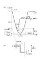
図7は本発明の実施形態に係る鍛造装置100の動作の一例を示すフローチャートである。図8は本発明の実施形態に係る鍛造装置100の動作の一例を示す図である。詳細には、図8(a)は上パンチ11と、下パンチ13と、上型12のストリッパー12a、下型14の可動下ダイ14aの動きの一例を示す図、図8(b)は成形された素材5の一例を示す断面図である。図8(a)において、各線は、上パンチ11の下端位置、上型12のストリッパー12aの下端位置、下型14の可動下ダイ14aの上端位置、下パンチ13の上端位置を示している。
FIG. 7 is a flowchart showing an example of the operation of the forging
次に、鍛造装置100の動作の一例を、図1から図8などを参照しながら説明する。
Next, an example of the operation of the forging
初期状態では、鍛造装置100の制御部110は、スライド部材21が上死点位置となるように、駆動部160aが設定されている。この状態では、図3に示したように、上型12のストリッパー12aおよび上パンチ11は、下型14の可動下ダイ14aおよび下パンチ13と離間した状態となっている。
In the initial state, the
図3に示したように、下型14の可動下ダイ14aと下パンチ13の上に、鍛造対象の素材5である板材が載置される。この場合、下パンチ13上に、板材などの素材における筒形状体の形成位置と一致するように、素材5を配置する。
As shown in FIG. 3, a plate material that is the
図3に示したように、下型14の下ホルダ14bに形成された第2の孔部14dは、第1のパンチ11(上パンチ)に対応した位置に形成され、且つ、第1のパンチ11(上パンチ)の端部の外形寸法11L(上型12のストリッパー12aの孔部の内形寸法)よりも大きい内径寸法14L(下パンチ13の外形寸法)となるように形成されている。
As shown in FIG. 3, the
次に、ステップST1において、制御部110は、図4(a)に示したように、駆動部160を駆動して、第1の型である上型12のストリッパー12aおよび第2の型である下型14の可動下ダイ14aにより素材5の端部付近を挟圧する。また、この場合、制御部110は、上パンチ11と下パンチ13とにより素材5の中央部付近を挟圧する。
Next, in step ST1, as shown in FIG. 4A, the
ステップST2において、制御部110は、図4(b)に示したように、駆動部160(160a、160b、160c、160d)をそれぞれ駆動して、第1のパンチ11(上パンチ)および第2のパンチ13(下パンチ)により挟圧した素材部分(板材)の厚みを減少させるように、第1のパンチ11(上パンチ)、および、第2のパンチ13(下パンチ)を駆動制御した場合、第1のパンチ11(上パンチ)と第2のパンチ13(下パンチ)により挟圧した素材部分5bの厚み5eの減少量(体積減少量:減少部分5ed)に応じて、上型12のストリッパー12aと下型14の可動下ダイ14aにより挟圧した素材部分の厚みを略保った状態で、上型12のストリッパー12aと下型14の可動下ダイ14aにより挟圧される素材部分5aを、上型12のストリッパー12a側に移動させ、且つ、第1のパンチ11(上パンチ)と第2の孔部14dの隙間に材料流動させることにより形成される筒状部5pを増加させる駆動制御を行う。
In step ST2, as shown in FIG. 4B, the
鍛造装置100は、上述した駆動制御を行うので、素材5の加工時、素材5の加工部位以外の部分が加工部位に引き込まれたりしない、加工部位から素材材料がはみ出さない、板形状に影響を与えないように成形を行うことができる。
Since the forging
次に、図5に示したように、制御部110は、駆動部160を駆動して、スライド部材21の上ダイセット212、上型12のストリッパー12a、上パンチ11を上方に移動させる。
Next, as shown in FIG. 5, the
詳細には、図8に示したように、素材5の上端部位置k(上型12の下端部位置)は、上パンチ11と下パンチ13により挟圧される部分の板厚の減少量に応じて、上昇するように移動する。
Specifically, as shown in FIG. 8, the upper end position k (the lower end position of the upper mold 12) of the
図9は、複数の上パンチ11及び下パンチ13を備えた鍛造装置100の一例を示す図である。詳細には、図9(a)は上型12のストリッパー12a、下型14の可動下ダイ14a、上パンチ11、下パンチ13により素材5を挟圧した状態の一例を示す断面図、図9(b)は上パンチ11、下パンチ13により挟圧して塑性流動させた素材5の一例を示す断面図、図9(c)は上型12のストリッパー12aと下型14の可動下ダイ14aが離間した状態の一例を示す図である。
FIG. 9 is a diagram illustrating an example of a forging
図9に示した鍛造装置100は、上型12のストリッパー12aに形成された複数の孔部に上パンチ11がそれぞれ貫通自在に設けられ、下型14の可動下ダイ14aに形成された複数の孔部に下パンチ13がそれぞれ設けられている。
鍛造装置100は、上述したように、板材などの素材5の加工時、素材5の加工部位以外の部分が加工部位に引き込まれたりしない、加工部位から素材の材料がはみ出さない、素材の板形状部分に影響を与えないように成形を行うことができる。このため、図9に示した鍛造装置100は、板材などの素材5に、連続的に密接して筒形状部を加工成形することができる。
The forging
As described above, the forging
以下、図9に示した鍛造装置100の動作を詳細に説明する。
図9(a)に示したように、鍛造装置100の制御部110は、上型12のストリッパー12aと下型14の可動下ダイ14aにより板材などの素材5を挟圧し、且つ、複数の上パンチ11と下パンチ13により、素材5を挟圧する。
Hereinafter, the operation of the forging
As shown in FIG. 9A, the
図9(b)に示したように、制御部110は、駆動部160(160a、160b、160c、160d)を駆動して、複数の第1のパンチ11(上パンチ)および複数の第2のパンチ13(下パンチ)により挟圧した素材部分の厚みを減少させるように、第1のパンチ11(上パンチ)、および、第2のパンチ13(下パンチ)を駆動制御した場合、第1のパンチ11(上パンチ)と第2のパンチ13(下パンチ)により挟圧した素材部分5bの厚み5eの減少量(体積減少量:減少部分5ed)に応じて、第1の型である上型12のストリッパー12aと第2の型である下型14の可動下ダイ14aにより挟圧した素材部分の厚みを略保った状態で、上型12のストリッパー12aと下型14により挟圧される素材部分5aを、上型12のストリッパー12a側に移動させ、且つ、第1のパンチ11(上パンチ)と第2の孔部14dの隙間に材料流動させることにより形成される筒状部5pを増加させる駆動制御を行う。
As shown in FIG. 9B, the
この際、鍛造装置100の制御部110は、板材などの素材5の加工部位以外の部分が加工部位に引き込まれたりしない、加工部位から素材の材料がはみ出さない、素材の板形状部分に影響を与えないように、駆動部160を駆動制御する。
At this time, the
そして、図9(c)に示したように、鍛造装置10の制御部110は、駆動部160を駆動して、スライド部材21の上ダイセット212、上型12のストリッパー12a、上パンチ11などを上方に移動させる。
9C, the
このように、鍛造装置100は、板材などの素材5に連続的に密接して、有底の筒形状体を成形することができる。
In this way, the forging
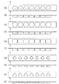
図10、図11は、複数の筒形状部を成形した素材5の一例を示す図である。上記実施形態では、鍛造装置100が板材などの一つの鍛造素材5を鍛造加工により成形して、一つの有底の筒形状体5tを作製したが、この形態に限られるものではない。例えば、図10に示したように、鍛造装置100は、一つの鍛造素材5に複数の筒形状体5tを同時に成形するように構成されていてもよい。
10 and 11 are diagrams illustrating an example of the
また、円筒形状体に限られるものではなく、例えば、鍛造装置100は、図10(a)、図10(b)に示したように、断面形状が偏平な楕円形状(ソラマメ形状)の有底の筒形状体を複数成形するように構成されていてもよい。
Further, the forging
鍛造装置100は、例えば、図10(c)、図10(d)に示したように、複数の有底の円筒形状体を成形するように構成されていてもよい。
The forging
また、鍛造装置100は、図10(e)、図10(f)に示したように、有底の四角筒形状体を複数成形するように構成されていてもよい。
Further, the forging
また、鍛造装置100は、図10(g)、図10(h)に示したように、断面形状が十字形状の有底の筒形状体を複数成形するように構成されていてもよい。
Further, as shown in FIGS. 10G and 10H, the forging
また、鍛造装置100は、図10(i)、図10(j)に示したように、断面形状が略三角形状の有底の筒形状体を複数成形するように構成されていてもよい。
Further, as shown in FIGS. 10 (i) and 10 (j), the forging
また、鍛造装置100は、素材5に有底の筒形状部を成形した後、必要に応じて、2次加工や3次加工を行うことにより、図11(a)、図11(b)に示したように、多段状に成形するように構成されていてもよい。この場合、素材5を複雑な形状に成形することができる。
In addition, the forging
また、鍛造装置100は、据込み加工などの予備成形された素材5により、図12(a)に示したようなフランジ付きの素材5などに、本発明に係る鍛造加工を施すことにより、図12(b)に示したように、比較的深い有底の筒形状体5tを容易に成形することができる。例えば、電池ケースなどの比較的深い有底の筒形状体5tを作製する際に、上記本発明に係る鍛造加工法を採用することで、容易にそれを作製することができる。
ここで、据え込み加工とは、材料を長さ方向に圧縮してその長さの一部または全部の断面を大きくする加工法である。
Further, the forging
Here, the upsetting process is a processing method in which a material is compressed in the length direction to enlarge a part or all of the cross section of the length.
また、図13(a)、図13(b)に示したように、鍛造装置100は、例えば、素材5の板材に、筒形状体5tを一つずつ、加工場所をずらして複数回加工することにより、素材5に複数の筒形状体5tを成形するように構成されていてもよい。
また、鍛造装置100は、例えば、図13(c)に示したように、素材5の板材に、材料送り方向と直交する方向に複数個の筒形状体5tが並ぶように、一列ずつ、加工場所をずらして複数回加工することにより、素材5に複数の筒形状体5tをマトリクス状に成形するように構成されていてもよい。
また、鍛造装置100は、例えば、図13(d)に示したように、素材5の板材に、材料送り方向と直交する方向に複数個の筒形状体5tが並ぶように、3列など複数列ずつ、加工場所をずらして複数回加工することにより、素材5に複数の筒形状体5tをマトリクス状に成形するように構成されていてもよい。
Further, as shown in FIGS. 13A and 13B, the forging
Further, the forging
In addition, as shown in FIG. 13D, the forging
以上、説明したように、本発明の実施形態に係る鍛造装置100は、鍛造の素材5を成形する。この鍛造装置100は、板材などの素材5を挟圧する第1の型である上型12および第2の型である下型14と、詳細には、上型12のストリッパー12aおよび下型4の可動下ダイ14aと、上型12のストリッパー12aに形成された第1の孔部12dに貫通自在に設けられた第1のパンチ11(上パンチ)と、下型14の可動下ダイ14aに形成された第2の孔部14dに貫通自在に設けられた第2のパンチ13(下パンチ)と、上型12、および、下型14を駆動制御し、且つ、第1のパンチ11(上パンチ)、および/または、第2のパンチ13(下パンチ)を駆動制御する駆動制御部(制御部110、駆動部160)と、を有する。
下型14の可動下ダイ14aに形成された第2の孔部14dは、第1のパンチ11(上パンチ)に対応した位置に形成され、且つ、第1のパンチ11(上パンチ)の端部の外径よりも大きい内径に形成されている。
駆動制御部(制御部110、駆動部160)は、第1のパンチ11(上パンチ)および第2のパンチ13(下パンチ)により挟圧した素材部分の厚みを減少させるように、第1のパンチ11(上パンチ)、および、第2のパンチ13(下パンチ)を駆動制御した場合、第1のパンチ11(上パンチ)と第2のパンチ13(下パンチ)により挟圧した素材部分の厚みの減少量に応じて、上型12のストリッパー12aと下型14の可動下ダイ14aにより挟圧した素材部分の厚みを略保った状態で、上型12のストリッパー12aと下型14の可動下ダイ14aにより挟圧される素材部分を、上型12のストリッパー12a側に移動させ、且つ、第1のパンチ11(上パンチ)と第2の孔部14dの隙間に材料流動させることにより形成される筒状部を増加させる駆動制御を行う。
As described above, the forging
The
The drive control units (the
詳細には、駆動制御部(駆動制御部(制御部110、駆動部160)は、第1のパンチ11、第2のパンチ13による素材部分の厚みの減少量(体積減少量:減少部分5ed)と、第1のパンチ11(上パンチ)と第2の孔部14dの隙間に材料流動させることにより形成される筒状部5pの増加量(体積増加量:増加部分5pd)とが同じ、または略同じとなるように、上型12のストリッパー12aと下型14の可動下ダイ14aにより挟圧される素材部分を、上型のストリッパー12a側に移動させる駆動制御を行う。
Specifically, the drive control unit (the drive control unit (
このため、板材、予備成形された素材、などの素材5を、簡単に、短時間に、高精度に、有底筒状に鍛造加工を行うことができる鍛造装置100を提供することができる。
For this reason, it is possible to provide the forging
また、本発明の実施形態に係る鍛造装置100は、素材5の加工時、素材5の加工部位以外の部分が加工部位に引き込まれたりしない、加工部位から素材5の材料がはみ出さない、素材5の板形状部分に影響を与えないように、素材5に鍛造加工を施すことができるので、図8に示したように、素材5に連続的に密接して、有底の筒形状部を成形することができる。
In addition, the forging
また、鍛造装置100において、上パンチ11の下端部の形状、下型14の孔部14dの形状などとして、四角形状、多角形状、円形状などの所望の形状のものを採用することで、所望の形状の有底の筒形状体を形成することができる。このため、鍛造装置100により素材5を成形して形成される成形物は、有底の四角筒形状体、有底の多角筒形状体、有底の円筒形状体、などの所望の筒形状体である。
Further, in the forging
上述したように、本発明の実施形態に係る鍛造方法は、鍛造素材5を成形する鍛造装置100の鍛造方法であって、駆動制御部(制御部110、駆動部160)が、第1の型である上型12および第2の型である下型14、詳細には、上型12のストリッパー12aおよび下型14の可動下ダイ14aにより板材などの素材5を挟圧する第1のステップと、第1のパンチ11(上パンチ)および第2のパンチ13(下パンチ)により挟圧した素材部分の厚みを減少させるように、第1のパンチ11(上パンチ)、および/または、第2のパンチ13(下パンチ)を駆動制御した場合、第1のパンチ11(上パンチ)と第2のパンチ13(下パンチ)により挟圧した板材部分の厚みの減少量に応じて、上型12のストリッパー12aと下型14の可動下ダイ14aにより挟圧した板材部分の厚みを略保った状態で、上型12と下型14(下型)により挟圧される板材部分を、上型12のストリッパー12a側に移動させ、且つ、第1のパンチ11(上パンチ)と第2の孔部14dの隙間に材料流動させることにより形成される筒状部5pを増加させる駆動制御を行う第2のステップと、を有する。
As described above, the forging method according to the embodiment of the present invention is a forging method of the forging
すなわち、板状の素材5を、簡単に、短時間に、高精度に、有底筒状に鍛造加工を行うことができる鍛造方法を提供することができる。
That is, it is possible to provide a forging method capable of forging the plate-
また、例えば、絞り・しごき加工、トリム加工を繰り返し行う場合と比較して、本発明の実施形態に係る鍛造装置100は、トリム加工を行う工程を低減することができるので、高い材料利用率の加工を行うことができる。
In addition, for example, the forging
また、本発明の実施形態に係る鍛造装置100は、上述したように、金属製の板材などの鍛造素材5を、後方押し出し鍛造加工、背圧付加鍛造加工、冷間鍛造加工により成形する。このため、短時間に、高精度に、有底筒状に鍛造加工を行うことができる鍛造装置100を提供することができる。
In addition, as described above, the forging
また、本発明の実施形態に係る鍛造装置100は、駆動制御部(制御部110、駆動部160)が、第1の型である上型12のストリッパー12aに、第1のパンチ11(上パンチ)にかかる力とは独立した第1の拘束力を加え、且つ、第2の型である下型14の可動下ダイ14aに、第1のパンチ11にかかる力とは独立した第2の拘束力を加えるように駆動制御を行う。この場合、第2の拘束力は、第1の拘束力よりも大きいことが好ましい。
こうすることで、簡単な駆動制御により、簡単に、素材5である板材を成形して筒状部5pを形成することができる。
また、駆動制御部(制御部110、駆動部160)は、素材5の材料流動により、上パンチ11に沿ってはみ出したり、上パンチ11と孔部14dに沿って引き込まれたりしないように鍛造加工を行うことで、簡単に、有底筒形状体を成形することができる。
Further, in the forging
By doing so, the
Further, the drive control unit (the
尚、上記実施形態の鍛造装置100は、下パンチ13が台座20などに固定され、上型12のストリッパー12aと下型14の可動下ダイ14aにより挟圧される板材部分を、上型12のストリッパー12a側(上方向)に移動させたが、この形態に限られるものではない。
例えば、鍛造装置100は、上パンチ11と下パンチ13により板材などの素材5を挟圧した状態で、且つ、上型12のストリッパー12aと下型14の可動下ダイ14aにより素材5を挟圧した状態(固定)で、上パンチ11と下パンチ13により挟圧した板材部分を下方に移動するように構成してもよい。
また、鍛造装置100は、上パンチ11と下パンチ13により素材5を挟圧した状態で、且つ、上型12のストリッパー12aと下型14の可動下ダイ14aにより素材5を挟圧した状態で、上パンチ11と下パンチ13により挟圧した板材部分を、上型12のストリッパー12aと下型14の可動下ダイ14aにより挟圧した板材部分から離れる方向に移動するように構成してもよい。
In the forging
For example, the forging
The forging
<本発明の他の実施形態に係る鍛造装置>
図14は本発明の他の実施形態に係る鍛造装置の一例を示す図である。
図14に示した鍛造装置100は、プレス機に駆動装置(駆動部)が組み込まれた構造を有する。
詳細には、図14に示した鍛造装置は、第1のパンチ11(上パンチ)と、第2のパンチ13(下パンチ)と、上型12と、下型14と、などを有する。
上型12は、ストリッパー12a、上ホルダ12b、上プレート12c、などを有する。下型14は、可動下ダイ14a(下ストリッパー)、下ホルダ14b、下プレート14c、などを有する。また、本実施形態の鍛造装置は、制御部110(CPU)と、操作入力部120と、表示部130と、記憶部140と、位置検出部150と、駆動部160(160a、160b、160c、160d,160e)と、などを有する(不図示)。
<Forging device according to another embodiment of the present invention>
FIG. 14 is a view showing an example of a forging device according to another embodiment of the present invention.
The forging
Specifically, the forging device shown in FIG. 14 includes a first punch 11 (upper punch), a second punch 13 (lower punch), an
The
図14に示した鍛造装置100は、図1に示した鍛造装置と比較すると、上押え板31b、上バネホルダー31a、下バネホルダー32a、下押え板32bが設けられていない。
Compared with the forging device shown in FIG. 1, the forging
また、図14に示した鍛造装置100では、駆動部160d、160eの上端部が可動下ダイ14aに接続され、下端部がプレスボルスター201に接続された構造を有し、駆動部160b、160cの上端部がプレススライド211に接続され、下端部がストリッパー12aに接続された構造を有する。
Further, the forging
図14に示した鍛造装置100では、制御部110が駆動部160a,160b、160c、160d、160eを駆動させることにより、比較的大きいストロークでストリッパー12aや可動下ダイ14aを動作可能に構成されている。
In the forging
上述したように、ストリッパー12aや可動下ダイ14aの可動範囲が比較的大きい鍛造装置100を提供することができる。
As described above, the forging
図14に示した鍛造装置と、図1などに示した鍛造装置と同じ構成については、説明を省略する。 Description of the same configuration as the forging device shown in FIG. 14 and the forging device shown in FIG.
以上、本発明の実施形態について説明したが、本発明の実施形態の一部または全部は、以下の付記のように記載される。
[付記1]
鍛造の素材を成形する鍛造装置であって、
前記素材を挟圧する第1の型(上型)および第2の型(下型)と、
前記第1の型(上型)に形成された第1の孔部に貫通自在に設けられた第1のパンチ(上パンチ)と、
前記第2の型(下型)に形成された第2の孔部に貫通自在に設けられた第2のパンチ(下パンチ)と、
前記第1の型(上型)、および、前記第2の型(下型)、且つ、前記第1のパンチ(上パンチ)、および/または、前記第2のパンチ(下パンチ)を駆動制御する駆動制御部と、を有し、
前記第2の型(下型)に形成された前記第2の孔部は、前記第1のパンチ(上パンチ)に対応した位置に形成され、且つ、前記第1のパンチ(上パンチ)の端部の外形寸法よりも大きい内形寸法となるように形成され、
前記駆動制御部は、前記第1のパンチ(上パンチ)および前記第2のパンチ(下パンチ)により挟圧した素材部分の厚みを減少させるように、前記第1のパンチ(上パンチ)、および/または、前記第2のパンチ(下パンチ)を駆動制御した場合、前記第1のパンチ(上パンチ)と前記第2のパンチ(下パンチ)により挟圧した素材部分の厚みの減少量に応じて、前記第1の型(上型)と前記第2の型(下型)により挟圧した素材部分の厚みを略保った状態で、前記第1の型(上型)と第2の型(下型)により挟圧される素材部分を、前記第1の型(上型)側に移動させ、且つ、前記第1のパンチ(上パンチ)と前記第2の孔部の隙間に材料流動させることにより形成される筒状部を増加させる駆動制御を行うことを特徴とする
鍛造装置。
[付記2]
前記駆動制御部は、前記第1のパンチ、第2のパンチによる素材部分の厚みの減少量(体積減少量)と、第1のパンチ(上パンチ)と前記第2の孔部の隙間に材料流動させることにより形成される筒状部の増加量(体積増加量)とが同じ、または、略同じとなるように、前記第1の型(上型)と第2の型(下型)により挟圧される素材部分を、前記第1の型(上型)側に移動させる駆動制御を行うことを特徴とする付記1に記載の鍛造装置。
[付記3]
前記駆動制御部は、前記第1の型(上型)に、前記第1のパンチにかかる力とは独立した第1の拘束力を加え、且つ、前記第2の型(下型)に、前記第1のパンチにかかる力とは独立した第2の拘束力を加えるように駆動制御を行い、
前記第2の拘束力は、前記第1の拘束力よりも大きいことを特徴とする付記1または付記2に記載の鍛造装置。
[付記4]
前記素材を成形して形成される成形物は、少なくとも、有底の四角筒形状体、有底の多角筒形状体、有底の円筒形状体のいずれかであることを特徴とする付記1から付記3のいずれかに記載の鍛造装置。
[付記5]
鍛造素材である素材を成形する鍛造装置の鍛造方法であって、
前記鍛造装置は、前記素材を挟圧する第1の型(上型)および第2の型(下型)と、前記第1の型(上型)に形成された第1の孔部に貫通自在に設けられた第1のパンチ(上パンチ)と、前記第2の型(下型)に形成された第2の孔部に貫通自在に設けられた第2のパンチ(下パンチ)と、前記第1の型(上型)、及び、前記第2の型(下型)、前記第1のパンチ(上パンチ)、および/または、前記第2のパンチ(下パンチ)を駆動制御する駆動制御部と、を有し、
前記第2の型(下型)に形成された前記第2の孔部は、前記第1のパンチ(上パンチ)に対応した位置に形成され、且つ、前記第1のパンチ(上パンチ)の端部の外形寸法よりも大きい内形寸法となるように形成されており、
前記駆動制御部は、前記第1の型(上型)および前記第2の型(下型)により前記素材を挟圧するステップと、
前記第1のパンチ(上パンチ)および前記第2のパンチ(下パンチ)により挟圧した素材部分の厚みを減少させるように、前記第1のパンチ(上パンチ)、および、前記第2のパンチ(下パンチ)を駆動制御した場合、前記第1のパンチ(上パンチ)と前記第2のパンチ(下パンチ)により挟圧した素材部分の厚みの減少量に応じて、前記第1の型(上型)と前記第2の型(下型)により挟圧した素材部分の厚みを略保った状態で、前記第1の型(上型)と第2の型(下型)により挟圧される素材部分を、前記第1の型(上型)側に移動させ、且つ、前記第1のパンチ(上パンチ)と前記第2の孔部の隙間に材料流動させることにより形成される筒状部を増加させる駆動制御を行うステップと、
を有することを特徴とする鍛造方法。
As mentioned above, although embodiment of this invention was described, some or all of embodiment of this invention is described as the following additional remarks.
[Appendix 1]
A forging device for forming a forging material,
A first mold (upper mold) and a second mold (lower mold) for clamping the material;
A first punch (upper punch) provided so as to pass through a first hole formed in the first die (upper die);
A second punch (lower punch) provided so as to pass through a second hole formed in the second die (lower die);
Drive control of the first die (upper die), the second die (lower die), and the first punch (upper punch) and / or the second punch (lower punch) A drive control unit,
The second hole formed in the second die (lower die) is formed at a position corresponding to the first punch (upper punch), and the first punch (upper punch) It is formed to have an inner shape dimension that is larger than the outer dimension of the end,
The drive control unit includes the first punch (upper punch) and the first punch (upper punch) so as to reduce the thickness of the material portion clamped by the first punch (upper punch) and the second punch (lower punch), and / Or when the second punch (lower punch) is driven and controlled, depending on the amount of reduction in the thickness of the material portion sandwiched between the first punch (upper punch) and the second punch (lower punch) The first mold (upper mold) and the second mold in a state where the thickness of the material portion sandwiched between the first mold (upper mold) and the second mold (lower mold) is substantially maintained. The material portion clamped by the (lower die) is moved to the first die (upper die) side, and the material flows into the gap between the first punch (upper punch) and the second hole. A forging device that performs drive control to increase the number of cylindrical portions formed.
[Appendix 2]
The drive control unit is configured to reduce a material portion thickness reduction amount (volume reduction amount) by the first punch and the second punch, and a material in a gap between the first punch (upper punch) and the second hole portion. The first mold (upper mold) and the second mold (lower mold) so that the increase amount (volume increase amount) of the cylindrical portion formed by flowing is the same or substantially the same. The forging device according to
[Appendix 3]
The drive control unit applies a first restraining force independent of the force applied to the first punch to the first die (upper die), and to the second die (lower die), Performing drive control so as to apply a second restraining force independent of the force applied to the first punch,
The forging device according to
[Appendix 4]
From the
[Appendix 5]
A forging method of a forging device for forming a material that is a forging material,
The forging device is capable of penetrating through a first die (upper die) and a second die (lower die) that sandwich the material and a first hole formed in the first die (upper die). A first punch (upper punch) provided in a second punch (lower punch) provided in a second hole formed in the second die (lower die), Drive control for driving and controlling the first mold (upper mold), the second mold (lower mold), the first punch (upper punch), and / or the second punch (lower punch). And
The second hole formed in the second die (lower die) is formed at a position corresponding to the first punch (upper punch), and the first punch (upper punch) It is formed to have an inner shape dimension that is larger than the outer dimension of the end,
The drive control unit is configured to clamp the material by the first mold (upper mold) and the second mold (lower mold);
The first punch (upper punch) and the second punch so as to reduce the thickness of the material portion clamped by the first punch (upper punch) and the second punch (lower punch) When the drive control of the (lower punch) is performed, the first die (in accordance with the amount of reduction in the thickness of the material portion sandwiched between the first punch (upper punch) and the second punch (lower punch) ( The material is clamped by the first mold (upper mold) and the second mold (lower mold) while maintaining the thickness of the material portion clamped by the upper mold) and the second mold (lower mold). A cylindrical shape formed by moving a material portion to be moved to the first die (upper die) side and flowing the material in a gap between the first punch (upper punch) and the second hole portion. Performing drive control to increase the number of sections;
The forging method characterized by having.
以上、本発明の実施形態について図面を参照して詳述してきたが、具体的な構成はこれらの実施形態に限られるものではなく、本発明の要旨を逸脱しない範囲の設計の変更等があっても本発明に含まれる。
また、上述の各図で示した実施形態は、その目的及び構成等に特に矛盾や問題がない限り、互いの記載内容を組み合わせることが可能である。
また、各図の記載内容はそれぞれ独立した実施形態になり得るものであり、本発明の実施形態は各図を組み合わせた一つの実施形態に限定されるものではない。
As described above, the embodiments of the present invention have been described in detail with reference to the drawings. However, the specific configuration is not limited to these embodiments, and there are design changes and the like without departing from the gist of the present invention. Is included in the present invention.
Further, the embodiments described in the above drawings can be combined with each other as long as there is no particular contradiction or problem in the purpose and configuration.
Moreover, the description content of each figure can become independent embodiment, respectively, and embodiment of this invention is not limited to one embodiment which combined each figure.
5 素材(板材、予備成形された素材など:鍛造加工対象物)
5a ストリッパーにより挟圧される素材(板材)部分
5b 上パンチと下パンチにより挟圧される素材(板材)部分
5d 素材(板材)の厚み(鍛造加工前の素材の厚み、上型と下型により挟圧される素材部分の厚み)
5e 素材(板材)の厚み(鍛造加工により、上パンチと下パンチにより挟圧される素材部分の厚み)
5ed 減少部分
5p 筒状部
5pd 増加部分
5t 筒形状体
11 上パンチ(第1のパンチ)
11L 上パンチの外形寸法
12 上型(第1の型:ストリッパー)
12a ストリッパー
12b 上ホルダ
12c 上プレート
12d 孔部
13 下パンチ(第2のパンチ)
14 下型(第2の型:可動下ダイ)
14a 可動下ダイ(下ストリッパー)
14b 下ホルダ
14c 下プレート
14d 孔部
20 台座(下ダイセットおよびプレスボルスター)
21 スライド部材(プレススライドおよび上ダイセット)
22 ロッド(スライドガイド)
25 付勢部材(スプリング)
31 上ブロック
32 下ブロック
100 鍛造装置
110 制御部(CPU)
120 操作入力部
130 表示部
140 記憶部
150 位置検出部(センサ)
160 駆動部
201 プレスボルスター
202 下ダイセット
211 プレススライド
212 上ダイセット
5 Materials (plate materials, preformed materials, etc .: forging objects)
5a Material (plate material) portion clamped by
5e Thickness of material (plate material) (thickness of material portion clamped by upper punch and lower punch by forging)
5ed decreasing
11L External punch
14 Lower mold (second mold: movable lower die)
14a Movable lower die (lower stripper)
21 Slide member (press slide and upper die set)
22 Rod (slide guide)
25 Biasing member (spring)
31 Upper block 32 Lower block 100 Forging
120
Claims (6)
前記素材を挟圧する第1の型および第2の型と、
前記第1の型に形成された第1の孔部に貫通自在に設けられた第1のパンチと、
前記第2の型に形成された第2の孔部に貫通自在に設けられた第2のパンチと、
前記第1の型、および、前記第2の型を駆動制御し、且つ、前記第1のパンチ、および/または、前記第2のパンチを駆動制御する駆動制御部と、を有し、
前記第2の型に形成された前記第2の孔部は、前記第1のパンチに対応した位置に形成され、且つ、前記第1のパンチの端部の外形寸法よりも大きい内形寸法となるように形成され、
前記第1のパンチは、前記第1の孔部に摺動自在に貫通するように前記第1の孔部の内形寸法と同程度の外形寸法に形成されるとともに、前記第1の孔部に摺接する部分から第2のパンチ側の端部まで同じ外形寸法に形成され、前記第2の孔部は、前記第1の孔部の内形寸法よりも大きい内形寸法に形成され、
前記駆動制御部は、前記第1のパンチおよび前記第2のパンチにより挟圧した素材部分の厚みを減少させるように、前記第1のパンチ、および/または、前記第2のパンチを駆動制御した場合、前記第1のパンチと前記第2のパンチにより挟圧した素材部分の厚みの減少量に応じて、前記第1の型と前記第2の型により挟圧した素材部分の厚みを略保った状態で、前記第1の型および前記第2の型とこれらにより挟圧される素材部分を、前記第1の型側に移動させ、且つ、前記第1のパンチと前記第2の孔部の隙間に材料流動させることにより形成される筒状部を増加させる駆動制御を行うことを特徴とする鍛造装置。 A forging device for forming a forging material,
A first mold and a second mold for clamping the material;
A first punch provided so as to be able to pass through a first hole formed in the first mold;
A second punch provided so as to pass through a second hole formed in the second mold;
A drive control unit that drives and controls the first mold and the second mold, and drives and controls the first punch and / or the second punch, and
The second hole formed in the second mold is formed at a position corresponding to the first punch, and has an inner shape dimension larger than an outer dimension of an end portion of the first punch. Formed to be
The first punch is formed to have an outer dimension similar to the inner dimension of the first hole so as to slidably penetrate the first hole, and the first hole Are formed in the same outer dimensions from the portion in sliding contact to the end on the second punch side, the second hole portion is formed in an inner shape dimension larger than the inner shape dimension of the first hole portion,
The drive control unit drives and controls the first punch and / or the second punch so as to reduce the thickness of the material portion clamped by the first punch and the second punch. In this case, the thickness of the material portion clamped by the first mold and the second mold is substantially maintained according to the amount of decrease in the thickness of the material portion clamped by the first punch and the second punch. In this state, the first die and the second die and the material portion sandwiched between them are moved to the first die side, and the first punch and the second hole are moved. A forging device that performs drive control to increase a cylindrical portion formed by causing a material to flow in the gap.
鍛造装置は、前記素材を挟圧する第1の型および第2の型と、前記第1の型に形成された第1の孔部に貫通自在に設けられた第1のパンチと、前記第2の型に形成された第2の孔部に貫通自在に設けられた第2のパンチと、前記第1の型、および、前記第2の型を駆動制御し、且つ、前記第1のパンチ、および/または、前記第2のパンチを駆動制御する駆動制御部と、を有し、
前記第2の型に形成された前記第2の孔部は、前記第1のパンチに対応した位置に形成され、且つ、前記第1のパンチの端部の外形寸法よりも大きい内形寸法となるように形成されており、
前記第1のパンチは、前記第1の孔部に摺動自在に貫通するように前記第1の孔部の内形寸法と同程度の外形寸法に形成されるとともに、前記第1の孔部に摺接する部分から第2のパンチ側の端部まで同じ外形寸法に形成され、前記第2の孔部は、前記第1の孔部の内形寸法よりも大きい内形寸法に形成され、
前記駆動制御部は、前記第1の型および前記第2の型により前記素材を挟圧するステップと、
前記第1のパンチおよび前記第2のパンチにより挟圧した素材部分の厚みを減少させるように、前記第1のパンチ、および/または、前記第2のパンチを駆動制御した場合、前記第1のパンチと前記第2のパンチにより挟圧した素材部分の厚みの減少量に応じて、前記第1の型と前記第2の型により挟圧した素材部分の厚みを略保った状態で、前記第1の型および前記第2の型とこれらにより挟圧される素材部分を、前記第1の型側に移動させ、且つ、前記第1のパンチと前記第2の孔部の隙間に材料流動させることにより形成される筒状部を増加させる駆動制御を行うステップと、を有することを特徴とする鍛造方法。 A forging method in which a forging material is formed by a forging device ,
The forging device includes a first die and a second die for sandwiching the material, a first punch provided in a first hole portion formed in the first die, and the second punch. A second punch provided in a second hole formed in the mold of the first mold, the first mold, and the second mold are driven and controlled, and the first punch, And / or a drive control unit that drives and controls the second punch,
The second hole formed in the second mold is formed at a position corresponding to the first punch, and has an inner shape dimension larger than an outer dimension of an end portion of the first punch. Is formed to be
The first punch is formed to have an outer dimension similar to the inner dimension of the first hole so as to slidably penetrate the first hole, and the first hole Are formed in the same outer dimensions from the portion in sliding contact to the end on the second punch side, the second hole portion is formed in an inner shape dimension larger than the inner shape dimension of the first hole portion,
The drive control unit sandwiching the material with the first mold and the second mold;
When the driving of the first punch and / or the second punch is controlled so as to reduce the thickness of the material portion clamped by the first punch and the second punch, the first punch In accordance with the amount of decrease in the thickness of the material portion clamped by the punch and the second punch, the thickness of the material portion clamped by the first mold and the second mold is substantially maintained, and the first The first die and the second die and the material portion sandwiched between them are moved to the first die side, and the material is caused to flow into the gap between the first punch and the second hole. And a step of performing drive control to increase the cylindrical portion formed by the forging method.
前記素材を挟圧する第1の型および第2の型と、 A first mold and a second mold for clamping the material;
前記第1の型に形成された第1の孔部に貫通自在に設けられた第1のパンチと、 A first punch provided so as to be able to pass through a first hole formed in the first mold;
前記第2の型に形成された第2の孔部に貫通自在に設けられた第2のパンチと、 A second punch provided so as to pass through a second hole formed in the second mold;
前記第1の型、前記第2の型および前記第1のパンチを駆動制御する駆動制御部と、を有し、 A drive control unit that drives and controls the first mold, the second mold, and the first punch,
前記第2の型に形成された前記第2の孔部は、前記第1のパンチに対応した位置に形成され、且つ、前記第1のパンチの端部の外形寸法よりも大きい内形寸法となるように形成され、 The second hole formed in the second mold is formed at a position corresponding to the first punch, and has an inner shape dimension larger than an outer dimension of an end portion of the first punch. Formed to be
前記駆動制御部は、前記第1のパンチおよび前記第2のパンチにより挟圧した素材部分の厚みを減少させるように、前記第2のパンチを移動せずに前記第1のパンチを第2のパンチ側へ移動した場合に、前記第1のパンチと前記第2のパンチにより挟圧した素材部分の厚みの減少量に応じて、前記第1の型と前記第2の型により挟圧した素材部分の厚みを略保った状態で、前記第1の型および前記第2の型とこれらにより挟圧される素材部分を、前記第1の型側に移動させ、且つ、前記第1のパンチと前記第2の孔部の隙間に材料流動させることにより形成される筒状部を増加させる駆動制御を行うように構成され、 The drive control unit moves the first punch to the second without moving the second punch so as to reduce the thickness of the material portion clamped by the first punch and the second punch. The material clamped by the first mold and the second mold according to the amount of reduction in the thickness of the material portion clamped by the first punch and the second punch when moved to the punch side The first die and the second die and the material portion sandwiched between them are moved to the first die side while maintaining the thickness of the portion, and the first punch and It is configured to perform drive control to increase the cylindrical portion formed by flowing the material in the gap of the second hole portion,
前記駆動制御部は、前記第1の型および前記第2の型がその間に前記素材を挟んで第2のパンチ側へ一定量移動した後、前記第1のパンチの第2のパンチ側への移動と、前記第1の型および前記第2の型の逆方向への移動とを、前記第1のパンチと前記第2のパンチにより挟圧した素材部分の厚みが所定寸法になる時点まで同時進行し、この後、前記第1の型および前記第2の型の移動を停止して、前記第1のパンチを第1の型側へ移動させることを特徴とする鍛造装置。 The drive control unit is configured to move the first die and the second die to the second punch side by sandwiching the material therebetween and then move the first punch to the second punch side. The movement and the movement of the first die and the second die in the opposite directions are performed simultaneously until the thickness of the material portion clamped by the first punch and the second punch reaches a predetermined dimension. The forging apparatus is characterized in that the forging apparatus proceeds, and thereafter, the movement of the first mold and the second mold is stopped, and the first punch is moved to the first mold side.
前記素材を挟圧する第1の型および第2の型と、 A first mold and a second mold for clamping the material;
前記第1の型に形成された第1の孔部に貫通自在に設けられた第1のパンチと、 A first punch provided so as to be able to pass through a first hole formed in the first mold;
前記第2の型に形成された第2の孔部に貫通自在に設けられた第2のパンチと、 A second punch provided so as to pass through a second hole formed in the second mold;
前記第1の型、前記第2の型および前記第1のパンチを駆動制御する駆動制御部と、を有し、 A drive control unit that drives and controls the first mold, the second mold, and the first punch,
前記第2の型に形成された前記第2の孔部は、前記第1のパンチに対応した位置に形成され、且つ、前記第1のパンチの端部の外形寸法よりも大きい内形寸法となるように形成され、 The second hole formed in the second mold is formed at a position corresponding to the first punch, and has an inner shape dimension larger than an outer dimension of an end portion of the first punch. Formed to be
前記駆動制御部は、前記第1のパンチおよび前記第2のパンチにより挟圧した素材部分の厚みを減少させるように、前記第2のパンチを移動せずに前記第1のパンチを第2のパンチ側へ移動した場合に、前記第1のパンチと前記第2のパンチにより挟圧した素材部分の厚みの減少量に応じて、前記第1の型と前記第2の型により挟圧した素材部分の厚みを略保った状態で、前記第1の型および前記第2の型とこれらにより挟圧される素材部分を、前記第1の型側に移動させ、且つ、前記第1のパンチと前記第2の孔部の隙間に材料流動させることにより形成される筒状部を増加させる駆動制御を行うように構成され、 The drive control unit moves the first punch to the second without moving the second punch so as to reduce the thickness of the material portion clamped by the first punch and the second punch. The material clamped by the first mold and the second mold according to the amount of reduction in the thickness of the material portion clamped by the first punch and the second punch when moved to the punch side The first die and the second die and the material portion sandwiched between them are moved to the first die side while maintaining the thickness of the portion, and the first punch and It is configured to perform drive control to increase the cylindrical portion formed by flowing the material in the gap of the second hole portion,
前記第1のパンチおよび前記第1の型は、前記第2のパンチおよび前記第2の型よりも上側に設けられ、 The first punch and the first die are provided above the second punch and the second die,
前記第1のパンチおよび前記第1の型の上方側には、上下方向へ移動自在なスライド部材が設けられ、 On the upper side of the first punch and the first mold, a slide member that is movable in the vertical direction is provided,
前記第1のパンチは、前記スライド部材に固定され、 The first punch is fixed to the slide member;
前記第1の型は、前記スライド部材との間の距離を調整可能にする駆動部を介して、前記スライド部材に接続され、 The first mold is connected to the slide member via a drive unit that allows adjustment of a distance between the slide member and the first mold.
前記スライド部材は、回転駆動するクランク軸の回転により上下方向へ移動するように、前記クランク軸の偏心部分にコネクティングロッドを介して接続されていることを特徴とする鍛造装置。 The forging device, wherein the slide member is connected to an eccentric portion of the crankshaft via a connecting rod so as to move in the vertical direction by rotation of the crankshaft that is rotationally driven.
前記第2のパンチは、前記台座に固定され、 The second punch is fixed to the pedestal;
前記第2の型は、前記台座との間の距離を調整可能にする駆動部を介して、前記台座に接続されていることを特徴とする請求項4記載の鍛造装置。 The forging device according to claim 4, wherein the second die is connected to the pedestal via a drive unit that enables adjustment of a distance from the pedestal.
Priority Applications (4)
| Application Number | Priority Date | Filing Date | Title |
|---|---|---|---|
| JP2013104006A JP6095477B2 (en) | 2013-05-16 | 2013-05-16 | Forging apparatus and forging method |
| CN201480026857.9A CN105209191B (en) | 2013-05-16 | 2014-03-11 | Forging apparatus and forging method |
| US14/888,855 US9522422B2 (en) | 2013-05-16 | 2014-03-11 | Forging device and forging method |
| PCT/JP2014/056257 WO2014185138A1 (en) | 2013-05-16 | 2014-03-11 | Forging device and forging method |
Applications Claiming Priority (1)
| Application Number | Priority Date | Filing Date | Title |
|---|---|---|---|
| JP2013104006A JP6095477B2 (en) | 2013-05-16 | 2013-05-16 | Forging apparatus and forging method |
Publications (3)
| Publication Number | Publication Date |
|---|---|
| JP2014223647A JP2014223647A (en) | 2014-12-04 |
| JP2014223647A5 JP2014223647A5 (en) | 2016-03-31 |
| JP6095477B2 true JP6095477B2 (en) | 2017-03-15 |
Family
ID=51898123
Family Applications (1)
| Application Number | Title | Priority Date | Filing Date |
|---|---|---|---|
| JP2013104006A Active JP6095477B2 (en) | 2013-05-16 | 2013-05-16 | Forging apparatus and forging method |
Country Status (4)
| Country | Link |
|---|---|
| US (1) | US9522422B2 (en) |
| JP (1) | JP6095477B2 (en) |
| CN (1) | CN105209191B (en) |
| WO (1) | WO2014185138A1 (en) |
Cited By (1)
| Publication number | Priority date | Publication date | Assignee | Title |
|---|---|---|---|---|
| JP2017109208A (en) * | 2015-12-15 | 2017-06-22 | 東洋製罐グループホールディングス株式会社 | Manufacturing method of metal container |
Families Citing this family (4)
| Publication number | Priority date | Publication date | Assignee | Title |
|---|---|---|---|---|
| JP6109274B1 (en) * | 2015-11-09 | 2017-04-05 | かがつう株式会社 | Heat sink, method for manufacturing the heat sink, and electronic component package using the heat sink |
| WO2020090872A1 (en) * | 2018-10-31 | 2020-05-07 | 竹内 忍 | Machining device for plate material machining, and machining method |
| JP7044690B2 (en) * | 2018-11-26 | 2022-03-30 | 本田技研工業株式会社 | Manufacturing method of metal parts |
| CN111482515B (en) * | 2020-03-27 | 2021-12-21 | 江苏大学 | High-strength aluminum alloy cylindrical deep-drawing part die and matched extrusion-drawing-quenching process |
Family Cites Families (8)
| Publication number | Priority date | Publication date | Assignee | Title |
|---|---|---|---|---|
| DE1452495A1 (en) | 1962-05-28 | 1969-03-27 | Louis Vetter Tuben Und Metallk | Method and device for manufacturing a container open on one side |
| JP2783310B2 (en) * | 1993-01-28 | 1998-08-06 | トヨタ車体株式会社 | Embossing method |
| JPH07266100A (en) | 1994-03-31 | 1995-10-17 | Toyota Motor Corp | Method and device for setting pressing condition |
| JP2001137961A (en) * | 1999-11-08 | 2001-05-22 | Matsushita Electric Ind Co Ltd | Sheet metal forming method |
| JP4328847B2 (en) * | 2003-11-25 | 2009-09-09 | 株式会社デンソー | Method for manufacturing cylindrical member |
| JP2006272458A (en) * | 2005-03-04 | 2006-10-12 | Seiko Epson Corp | Shaft forming method |
| DE112009003609T5 (en) * | 2008-11-18 | 2012-07-05 | Topy Kogyo K.K. | METHOD FOR PRODUCING A TUBULAR COMPONENT |
| CN102489578B (en) * | 2011-12-07 | 2013-10-16 | 佛山市埃申特科技有限公司 | Method for processing ultrathin cylindrical stainless steel thin-film tube |
-
2013
- 2013-05-16 JP JP2013104006A patent/JP6095477B2/en active Active
-
2014
- 2014-03-11 US US14/888,855 patent/US9522422B2/en active Active
- 2014-03-11 WO PCT/JP2014/056257 patent/WO2014185138A1/en active Application Filing
- 2014-03-11 CN CN201480026857.9A patent/CN105209191B/en active Active
Cited By (1)
| Publication number | Priority date | Publication date | Assignee | Title |
|---|---|---|---|---|
| JP2017109208A (en) * | 2015-12-15 | 2017-06-22 | 東洋製罐グループホールディングス株式会社 | Manufacturing method of metal container |
Also Published As
| Publication number | Publication date |
|---|---|
| CN105209191A (en) | 2015-12-30 |
| CN105209191B (en) | 2017-06-20 |
| US20160074929A1 (en) | 2016-03-17 |
| WO2014185138A1 (en) | 2014-11-20 |
| JP2014223647A (en) | 2014-12-04 |
| US9522422B2 (en) | 2016-12-20 |
Similar Documents
| Publication | Publication Date | Title |
|---|---|---|
| JP6095477B2 (en) | Forging apparatus and forging method | |
| CN102205372B (en) | Disposable arc-rolling and forming die | |
| KR101706100B1 (en) | Tester for obtaining forming limit diagram | |
| US9498813B2 (en) | Multipoint stretch forming apparatus enabling individual clamping control for manufacturing a curved panel | |
| JP6051052B2 (en) | Press part molding method, press part manufacturing method, and press part molding die | |
| CN107214281B (en) | A kind of ship machine connecting rod forging blanking mold and application method | |
| CN202097282U (en) | One-step curling die | |
| WO2017006830A1 (en) | Protrusion molding device, protrusion molding method, and molded article | |
| JP6673760B2 (en) | Projection forming apparatus, projection forming method | |
| KR101751160B1 (en) | Press molding method for cup-shaped member | |
| JP6388500B2 (en) | FORGING APPARATUS, FORGING METHOD, AND METHOD FOR PRODUCING MOLDED ARTICLE | |
| JP5941369B2 (en) | Hydraulic molding method and hydraulic molding apparatus | |
| JP2016132018A (en) | Bending method, back gauge device, and press brake | |
| JP4677821B2 (en) | Manufacturing method and manufacturing apparatus for differential thickness plate | |
| JP2011005529A (en) | Method and device for forming fin collar of heat exchanging fin | |
| CN206199981U (en) | Bend forming die | |
| JP5981471B2 (en) | Cold forging press apparatus and cold forging press method | |
| US11648599B2 (en) | Method and system for forming protrusions, and method for manufacturing metal component having protrusions | |
| JP6187238B2 (en) | Press molding method and press molding apparatus | |
| CN106391853A (en) | Bending forming die | |
| JP6288401B1 (en) | Blank material manufacturing method and press-molded product manufacturing method | |
| JP4832476B2 (en) | Metal container manufacturing method and metal container manufacturing apparatus | |
| JP2005279677A (en) | Method and apparatus for press-forming metallic sheet | |
| CN108421947A (en) | A kind of enclosed forge die | |
| JP2014223661A (en) | Cup molding method |
Legal Events
| Date | Code | Title | Description |
|---|---|---|---|
| A521 | Request for written amendment filed |
Free format text: JAPANESE INTERMEDIATE CODE: A523 Effective date: 20160212 |
|
| A621 | Written request for application examination |
Free format text: JAPANESE INTERMEDIATE CODE: A621 Effective date: 20160212 |
|
| TRDD | Decision of grant or rejection written | ||
| A01 | Written decision to grant a patent or to grant a registration (utility model) |
Free format text: JAPANESE INTERMEDIATE CODE: A01 Effective date: 20170117 |
|
| A61 | First payment of annual fees (during grant procedure) |
Free format text: JAPANESE INTERMEDIATE CODE: A61 Effective date: 20170214 |
|
| R150 | Certificate of patent or registration of utility model |
Ref document number: 6095477 Country of ref document: JP Free format text: JAPANESE INTERMEDIATE CODE: R150 |
|
| R250 | Receipt of annual fees |
Free format text: JAPANESE INTERMEDIATE CODE: R250 |
|
| R250 | Receipt of annual fees |
Free format text: JAPANESE INTERMEDIATE CODE: R250 |
|
| R250 | Receipt of annual fees |
Free format text: JAPANESE INTERMEDIATE CODE: R250 |
|
| R250 | Receipt of annual fees |
Free format text: JAPANESE INTERMEDIATE CODE: R250 |
|
| R250 | Receipt of annual fees |
Free format text: JAPANESE INTERMEDIATE CODE: R250 |